WO2020166259A1 - ワークの切断方法及びワークの切断装置 - Google Patents
ワークの切断方法及びワークの切断装置 Download PDFInfo
- Publication number
- WO2020166259A1 WO2020166259A1 PCT/JP2020/001085 JP2020001085W WO2020166259A1 WO 2020166259 A1 WO2020166259 A1 WO 2020166259A1 JP 2020001085 W JP2020001085 W JP 2020001085W WO 2020166259 A1 WO2020166259 A1 WO 2020166259A1
- Authority
- WO
- WIPO (PCT)
- Prior art keywords
- wire
- groove
- wire guide
- cutting
- unused
- Prior art date
- Legal status (The legal status is an assumption and is not a legal conclusion. Google has not performed a legal analysis and makes no representation as to the accuracy of the status listed.)
- Ceased
Links
Images




Classifications
-
- B—PERFORMING OPERATIONS; TRANSPORTING
- B28—WORKING CEMENT, CLAY, OR STONE
- B28D—WORKING STONE OR STONE-LIKE MATERIALS
- B28D5/00—Fine working of gems, jewels, crystals, e.g. of semiconductor material; apparatus or devices therefor
- B28D5/04—Fine working of gems, jewels, crystals, e.g. of semiconductor material; apparatus or devices therefor by tools other than rotary type, e.g. reciprocating tools
-
- B—PERFORMING OPERATIONS; TRANSPORTING
- B24—GRINDING; POLISHING
- B24B—MACHINES, DEVICES, OR PROCESSES FOR GRINDING OR POLISHING; DRESSING OR CONDITIONING OF ABRADING SURFACES; FEEDING OF GRINDING, POLISHING, OR LAPPING AGENTS
- B24B27/00—Other grinding machines or devices
- B24B27/06—Grinders for cutting-off
-
- H—ELECTRICITY
- H10—SEMICONDUCTOR DEVICES; ELECTRIC SOLID-STATE DEVICES NOT OTHERWISE PROVIDED FOR
- H10P—GENERIC PROCESSES OR APPARATUS FOR THE MANUFACTURE OR TREATMENT OF DEVICES COVERED BY CLASS H10
- H10P52/00—Grinding, lapping or polishing of wafers, substrates or parts of devices
Definitions
- the present invention relates to a work cutting method and a work cutting device.
- the wire saw includes a work (for example, an ingot of a brittle material such as silicon, glass, or ceramics, which is obtained by running a wire (high-strength steel wire) at a high speed and applying slurry to the wire (hereinafter, simply referred to as an ingot). It is also a cutting device that cuts many wafers at the same time.
- a work for example, an ingot of a brittle material such as silicon, glass, or ceramics, which is obtained by running a wire (high-strength steel wire) at a high speed and applying slurry to the wire (hereinafter, simply referred to as an ingot). It is also a cutting device that cuts many wafers at the same time.
- Fig. 9 shows an outline of a general example of a wire saw.
- the wire saw 100 mainly includes a wire 101 for cutting an ingot (work) 104, a wire row 111 formed by winding the wire 101 around a plurality of wire guides 102, and a wire 101.
- a tension applying mechanism (not shown) for applying a tension
- an ingot feeding means (not shown) for feeding the ingot (work) 104 to be cut, and the like are provided.
- the wire 101 is unwound from one of the wire reels 103, and enters the wire guide 102 via a tension applying mechanism.
- the wire 101 is wound around the wire guide 102 about 300 to 400 times, and then wound around the wire reel 103 ′ via the other tension applying mechanism.
- the wire guide 102 is a roller in which a resin such as polyurethane is press-fitted around a steel cylinder, and grooves are cut on its surface at a constant pitch.
- the wound wire 101 is predetermined by a drive motor. It can be driven in a reciprocating direction in a cycle.
- FIG. 10 shows an installation state of the wire 101 in the groove of the wire guide 102.
- Warp is a shape parameter related to the deviation from the center line surface of the wafer, and is the maximum in-plane distance between the virtual center plane of the wafer that is not fixed by suction and the reference plane.
- Bow in the figure is an evaluation similar to Warp, but is a shape parameter of the distance between the center of the wafer and the reference plane.
- the measuring method is specified by JEIDA-43-1999 and ASTM F1530-94.
- Patent Document 2 when the ingot is cut, the displacement amount of the ingot that changes in the axial direction is measured, and the displacement amount in the axial direction of the grooved roller is controlled correspondingly (cooling water temperature flowing in the grooved roller, By adjusting the flow rate, etc.), the wire is cut while controlling the relative position of the wire with respect to the entire length of the ingot that changes in the axial direction.
- the V-shaped and U-shaped cross-sectional shapes of the groove of the wire guide used in the above-mentioned wire saw are known, and various opening angles of the groove such as 40 degrees to 110 degrees are used.
- various opening angles of the groove such as 40 degrees to 110 degrees are used.
- the opening angle of the groove is large, workability such as delivery of the wire is excellent, and when it is narrow, the wire holding effect tends to be good. From the viewpoint of stabilizing the Warp value of the work, it is desirable that the opening angle of the guide groove is narrow.
- the groove is gradually cut and deformed by the wire while cutting the work.
- the present inventor diligently investigated the transition of the Warp value of the work after cutting in the cutting of the work using the wire saw, and found that the Warp value of the work in the cutting at the initial stage of the wire guide life (initial use of the wire guide) It was found that the average value and the variation were large.
- the present invention has been made in order to solve the above problems, and a good and stable work shape (Warp value) from the initial use of the wire guide (immediately after the start of use) while suppressing a decrease in production capacity (throughput). It is an object of the present invention to provide a work cutting method and a work cutting device, which can obtain the quality of the work that does not depend on the life of the wire guide.
- the present invention has been made in order to achieve the above-mentioned object, and a wire is formed by spirally winding a wire around a plurality of cylindrical wire guides that are installed so that their rotation axis directions are parallel to each other. While the wire is running in the axial direction, the work is pressed against the wire row, and is simultaneously cut into wafers at a plurality of locations, wherein the wire guide has a predetermined outer surface along the rotation direction.
- the groove has a plurality of grooves formed at a pitch of, and the cross-sectional shape of the groove in the unused wire guide is located at least on the outer surface side of the wire guide, and the opposing groove walls have a first opening angle ( ⁇ 1 ), a groove upper part, a groove lower part located below the groove upper part and having opposing second groove angles ( ⁇ 2 ) and a groove bottom part located at the lower end of the groove.
- the first opening angle ( ⁇ 1 ) and the second opening angle ( ⁇ 2 ) are in the relationship of ⁇ 1 > ⁇ 2
- the maximum groove width of the unused groove portion of the wire guide is the maximum.
- the value (W 0,max ) is equal to or larger than the wire diameter ( ⁇ 0 ) of the unused wire, and the minimum value (W 0,min ) of the groove width under the groove of the unused wire guide is Using the unused wire and the unused wire guide, which are in a relationship of less than the wire diameter ( ⁇ 0 ) of the unused wire, the unused wire is connected to the bottom of the groove of the unused wire guide.
- a method for cutting a work is provided, which is installed in contact with the groove wall and not in contact with the groove bottom, and starts cutting the work in a state in which the wire does not contact the groove bottom.
- the wire may be a method of cutting the groove wall, and further, as the cutting of the workpiece progresses, the wire contacts the groove bottom portion.
- the method of cutting the work may be a method of cutting the groove bottom.
- the maximum value (W 0,max ) of the groove width of the groove lower part in the plurality of grooves and/or the second opening angle ( ⁇ 2 ) is set to It is possible to use a work cutting method that uses a tool that is changed in the traveling direction.
- a plurality of cylindrical wire guides which are arranged at a predetermined interval so that their rotation axis directions are parallel to each other, and grooves are formed on the outer surface at a predetermined pitch, respectively, and in the grooves of the wire guides.
- a wire row formed by a wire spirally wound at a predetermined pitch, and pressing the workpiece against the wire row while causing the wire to travel in the axial direction by rotating the wire guide.
- a cutting device for simultaneously cutting into a wafer at a plurality of locations, wherein the cross-sectional shape of the groove in the wire guide is located at least on the outer surface side of the wire guide, and the opposing groove walls have a first opening angle.
- the work cutting method of the present invention it is possible to obtain a good Warp value for a work from the beginning of the wire guide life (the beginning of use of the wire guide) while suppressing a decrease in cutting speed (production capacity). And, it becomes possible to stabilize. Further, according to the work cutting device of the present invention, the Warp value of the work is made good from the beginning of the wire guide life (the beginning of use of the wire guide) while suppressing a decrease in cutting speed (production capacity), and , Can be stabilized.
- FIG. 8 is an enlarged view of the initial wire guide life in FIG. 7.
- a general example of a wire saw is shown below.
- channel of a wire guide is shown. It is a figure which shows the definition of Warp.
- the present inventors formed a wire row by spirally winding a wire around a plurality of cylindrical wire guides installed so that the rotational axis directions of the wires are parallel to each other, While the wire is traveling in the axial direction, a work is pressed against the wire row, and at the same time, a method of cutting into a wafer shape at a plurality of locations, wherein the wire guide has a predetermined outer surface along a rotational direction.
- the groove has a plurality of grooves formed at a pitch, and the cross-sectional shape of the groove in the unused wire guide is located at least on the outer surface side of the wire guide, and the opposing groove walls have a first opening angle ( ⁇ ).
- the first opening angle ( ⁇ 1 ) and the second opening angle ( ⁇ 2 ) have a relationship of ⁇ 1 > ⁇ 2 , and the maximum value of the groove width of the unused wire guide at the lower part of the groove.
- (W 0,max ) is equal to or larger than the wire diameter ( ⁇ 0 ) of the unused wire, and the minimum value (W 0,min ) of the groove width under the groove of the unused wire guide is Using the unused wire and the unused wire guide, which are in a relationship of less than the wire diameter ( ⁇ 0 ) of the used wire, the unused wire, the unused wire guide, the groove lower part of the unused wire guide.
- the inventors of the present invention arranged the electrodes at a predetermined interval so that their rotation axis directions were parallel to each other, and formed grooves on the outer surface at a predetermined pitch.
- a groove bottom and a groove bottom located at the lower end of the groove are provided, and the first opening angle ( ⁇ 1 ) and the second opening angle ( ⁇ 2 ) have a relationship of ⁇ 1 > ⁇ 2.
- the maximum value (W 0,max ) of the groove width under the groove of the wire guide is equal to or larger than the wire diameter ( ⁇ 0 ) of the wire, and The minimum value (W 0,min ) of the groove width in the lower part of the groove is less than the wire diameter ( ⁇ 0 ) of the wire, and the wire was installed so as to contact the groove wall in the lower part of the groove.
- a work cutting device suppresses a decrease in cutting speed (production capacity), and the wire guide life is initial (initial use of the wire guide). From the above, it was found that the Warp value of the work can be made good and stable, and the present invention was completed.
- the Warp value of the work becomes large in both the average value and the variation at the early stage of the wire guide life (a certain period from the start of cutting the work). It was speculated that this was due to the vibration of the wire due to play in the lateral direction of the wire. Therefore, the structure of the work cutting device that can prevent the vibration of the wire due to the play in the lateral direction of the wire was examined. As a result, the wire is installed in the groove of the wire guide so that the groove of the wire and the groove of the wire guide are in a fixed relationship, and then the operation of the wire saw is started to suppress a decrease in the cutting speed (production capacity). In the meanwhile, the present invention has been completed by finding that the Warp value is stable from the beginning of the wire guide life (the initial use of the wire guide) to the end.
- the wire saw has a plurality of cylindrical wire guides, which are arranged at a predetermined interval so that the rotation axis directions thereof are parallel to each other, and each groove is formed on the outer surface at a predetermined pitch, and the groove of the wire guide. And a wire row formed of wires spirally wound at a predetermined pitch.
- the wire is rotated in the axial direction by rotating the wire guide, the work is pressed against the wire row, and simultaneously cut into wafers at a plurality of locations.
- the wire guide shown in FIG. 1 is also a typical example of the wire guide used in the work cutting method and work cutting apparatus of the present invention in an unused state.
- the first opening angle ( ⁇ 1 ) at the upper part of the groove and the lower part of the groove having the second opening angle ( ⁇ 2 ) have a relationship of ⁇ 1 > ⁇ 2 .
- the wire 101 and the wire guide 102 have the maximum groove width of the groove front of the groove of the wire guide 102, that is, the maximum groove width of the groove lower part.
- the value (W 0,max ) is equal to or larger than the wire diameter ( ⁇ 0 ) of the wire 101
- the minimum value (W 0,min ) of the groove width of the lower part of the wire guide groove is the wire diameter ( ⁇ 0 ) of the wire.
- the Warp value can be stably lowered immediately after the start of use of the work cutting device (from the beginning of the use period).
- the wire 101 when the wire 101 is installed in the groove of the wire guide 102 as described above and the operation of the wire saw is started, the wire 101 moves to the wire guide 102 in accordance with the progress of cutting of the workpiece (operation of the wire saw). The side wall 107 of the groove is scraped, and the groove bottom 108 is approached. Then, when a certain time has elapsed from the start of cutting the work (operation of the wire saw), the wire 101 comes into contact with the groove bottom portion 108 of the wire guide 102 and scrapes the groove bottom portion 108.
- the side wall 107 of the groove and the groove bottom 108 are scraped off and the groove shape according to the wire shape is self-advancing, so that the lateral vibration of the wire 101 is suppressed more stably. Therefore, the Warp value does not deteriorate.
- the cross-sectional shape of the groove bottom portion 108 of the wire guide 102 is not particularly limited, and may be an arc shape, a V shape, or a flat shape.
- An example in which the wire 101 is installed on such a wire guide 102 is shown in FIG. 2-4.
- the items described with reference to FIG. 2 are omitted as appropriate in the description of FIGS. 3-6 below. Further, FIG. 3-6 shows only one groove.
- the groove having the above-described shape can be manufactured relatively easily (low cost) and highly accurately, and the contact between the wire 101 and the groove bottom of the wire guide 102 can be prevented at low cost.
- the groove bottom 108 may be flat as long as the minimum groove width of the groove lower portion 106 is less than the wire diameter so that the wire does not contact the groove bottom 108.
- the wire guide is one in which the maximum value (W 0,max ) of the groove width of the groove lower part in the plurality of grooves and/or the second opening angle ( ⁇ 2 ) is changed in the traveling direction of the wire.
- W 0,max the maximum value of the groove width of the groove lower part in the plurality of grooves and/or the second opening angle ( ⁇ 2 ) is changed in the traveling direction of the wire.
- the wire tends to be thinned by about 10% in width by use. Therefore, the portion of the wire with a long cutting history becomes thinner than the unused portion or the portion with a short cutting history. In this way, since the line width of the wire in use may vary depending on the portion of the wire, if the wire guide is one in which the shapes of the plurality of grooves are changed in the traveling direction of the wire as described above. In the early stage of the wire guide life, the non-contact state between the wire and the groove bottom of the wire guide can be stably realized.
- the first opening angle ( ⁇ 1 ) of the groove upper portion in the groove of the wire guide 102 is preferably 60 to 110°. By setting in such a range, the cutting device has more excellent workability of the wire delivery work. Further, the second opening angle ( ⁇ 2 ) at the bottom of the groove is preferably 20 to 60°. By setting in such a range, the cutting device can hold the wire more stably and can manufacture a wire having a low Warp value.
- the shapes of the wire and the groove are set so that the upper part of the wire is positioned above the upper end (groove opening) of the lower part of the groove at the start of use. It is preferable to set. With this configuration, the life of the wire guide 102 can be extended.
- the radius of curvature R of the groove bottom and the wire diameter ( ⁇ 0 ) are preferably set such that R/ ⁇ 0 is in the range of less than 0.5. With such a relationship, the non-contact state between the wire and the groove bottom portion 108 of the wire guide 102 can be more stably and reliably realized in the initial stage of cutting.
- wire guide 102 it is possible to preferably use one in which a resin such as polyurethane (ester-based or ether-based) is press-fitted around a steel cylinder. Further, as the work cutting device, any of a free-abrasive grain type and a fixed-abrasive type can be applied.
- a resin such as polyurethane (ester-based or ether-based) is press-fitted around a steel cylinder.
- the shape having the apex at the connecting portion between the groove upper portion and the groove lower portion is shown, but the connection may be smooth.
- a wire is formed by spirally winding a wire around a plurality of cylindrical wire guides that are installed so that the rotation axis directions thereof are parallel to each other.
- the cross-sectional shape of the groove in the unused wire guide 102 is at least on the outer surface side of the wire guide, and the groove wall 107 facing the groove upper part 105 having the first opening angle ( ⁇ 1 ).
- a groove lower portion 106 located below the groove upper portion 105 and having an opposing groove wall 107 having a second opening angle ( ⁇ 2 ), and a groove bottom portion 108 located at the lower end of the groove.
- the opening angle ( ⁇ 1 ) and the second opening angle ( ⁇ 2 ) have a relationship of ⁇ 1 > ⁇ 2 .
- the unused wire 101 and the unused wire guide 102 having such a relationship are used, the unused wire 101 is in contact with the groove wall 107 of the groove lower portion 106 of the unused wire guide 102, and The wire guide 102 is installed without contacting the groove bottom 108, and cutting of the work is started in a state where the wire does not contact the groove bottom 108.
- a good and stable work shape (Warp value) can be obtained immediately after the start of use), and work quality independent of the life of the wire guide 102 can be obtained.
- the wire When the wire is installed in the wire guide groove as described above and the operation of the wire saw is started, immediately after the operation is started, the wire is supported (held) by the side wall at the lower part of the groove, and the work is cut (wire With the progress of (saw operation), the wire approaches the groove bottom while shaving the side surface of the wire guide groove, and the cutting progresses while automatically forming the optimum groove shape according to the wire diameter. Then, after a lapse of a certain time from the start of cutting the work (operation of the wire saw), the wire contacts the groove bottom of the wire guide and scrapes the groove bottom. Even when the wire comes into contact with the bottom of the groove of the wire guide in this way, the wire moves forward while scraping the groove, so that the vibration of the wire in the lateral direction remains suppressed, and therefore the Warp value does not deteriorate. ..
- the wire guide if the work is cut using one in which the shapes of the plurality of grooves are changed in the traveling direction of the wire as described above, at the beginning of the wire guide life, A non-contact state between the wire and the groove bottom of the wire guide can be stably realized. Further, since it is not necessary to reduce the cutting speed, it is possible to suppress a decrease in production capacity.
- Comparative Example 1 As an unused (new) wire guide, use a groove whose cross-sectional shape is one V-groove with an opening angle of 90 degrees and a groove width of 0.6 mm (600 ⁇ m) on the outer surface of the wire guide. Except for the above point, the cutting process was performed under the same conditions as in Example 1, and the shape of the obtained silicon wafer was measured.
- the wire was installed in the wire guide used in Comparative Example 1, the state shown in FIG. 5 was obtained.
- the wire was installed in the groove it had so-called play laterally in the groove.
- Table 1 shows typical values of cutting processing conditions (including the above conditions).
- the Warp value is considered to be stable from the beginning.
- the Warp value between lots or within a lot is low and stable. This is because the side surface (side wall) and the groove bottom surface of the wire guide groove are gradually ground toward the groove bottom portion by the running of the wire, and the side surface (side wall) and the groove bottom surface shape are adapted to the wire shape. It is believed that there is.
- the ratio between the groove width (W 0,max ) and the wire diameter ( ⁇ ) of the groove opening varies depending on the use condition.
- the groove width (W 0,max ) of the groove opening of the wire guide is set in the range of 1.01 to 1.30. It has been found that the radius of curvature R of the groove bottom portion of the groove is preferably set in the range of less than 0.5.
- the shape of the plurality of grooves is changed so as to gradually narrow the groove width (W 0,max ) of the groove frontage in the traveling direction of the wire as described above.
- setting within the above range is effective.
- Warp can be stably set to a good level immediately after the start of use of the wire guide, it is possible to obtain a work shape quality independent of the wire guide life, and the cutting speed. It was found that the work shape quality can be maintained without lowering the (production capacity).
- the present invention is not limited to the above embodiment.
- the above-described embodiment is an exemplification, and the invention having substantially the same configuration as the technical idea described in the scope of the claims of the present invention and exhibiting the same action and effect is the present invention It is included in the technical scope of.
Landscapes
- Engineering & Computer Science (AREA)
- Mechanical Engineering (AREA)
- Finish Polishing, Edge Sharpening, And Grinding By Specific Grinding Devices (AREA)
- Processing Of Stones Or Stones Resemblance Materials (AREA)
- Mechanical Treatment Of Semiconductor (AREA)
Abstract
本発明は、ワイヤーソーによるワークの切断方法であって、ワイヤーガイドは、外表面に、回転方向に沿って所定のピッチで形成された複数の溝を有し、未使用の前記ワイヤーガイドにおける前記溝の横断面形状は、少なくとも、ワイヤーガイド外表面側に位置し、対向する溝壁が第1の開き角度(θ1)を有する溝上部と、該溝上部の下に位置し、対向する溝壁が第2の開き角度(θ2)を有する溝下部と、前記溝の下端に位置する溝底部とを備え、前記第1の開き角度(θ1)と前記第2の開き角度(θ2)とが、θ1>θ2の関係にあり、前記未使用のワイヤーガイドの前記溝下部の溝幅の最大値(W0,max)が、未使用のワイヤーのワイヤー径(φ0)以上であり、前記未使用のワイヤーガイドの前記溝下部の前記溝幅の最小値(W0,min)が、前記未使用のワイヤーのワイヤー径(φ0)未満の関係にある、前記未使用のワイヤーと前記未使用のワイヤーガイドを用い、前記未使用のワイヤーを、前記未使用のワイヤーガイドの前記溝下部の前記溝壁に接し、かつ、前記溝底部に接触しない状態で設置し、前記ワイヤーが前記溝底部に接触しない状態で、前記ワークの切断を開始するワークの切断方法である。これにより、生産能力の低下を抑制しながら、ワイヤーガイドの使用初期から良好かつ安定したWarp値を得ることができるワークの切断方法が提供される。
Description
本発明は、ワークの切断方法及びワークの切断装置に関する。
近年、ウェーハの大型化(大直径化)が望まれており、この大型化に伴い、インゴットの切断には専らワイヤーソーが使用されている(例えば、特許文献1)。ワイヤーソーは、ワイヤー(高張力鋼線)を高速走行させて、ここにスラリーを掛けながら、ワーク(例えば、シリコン、ガラス、セラミックス等の脆性材料のインゴットが挙げられる。以下、単にインゴットと言うこともある)を押しあてて切断し、多数のウェーハを同時に切り出す切断装置である。
ここで、図9に、ワイヤーソーの一般例の概要を示す。図9に示すように、ワイヤーソー100は、主に、インゴット(ワーク)104を切断する為のワイヤー101、ワイヤー101を複数のワイヤーガイド102に巻掛けることで形成したワイヤー列111、ワイヤー101に張力を付与する為の張力付与機構(不図示)、切断されるインゴット(ワーク)104を送り出すインゴット送り手段(不図示)等を具備している。
ワイヤー101は、一方のワイヤーリール103から繰り出され、張力付与機構を経て、ワイヤーガイド102に入る。ワイヤー101はこのワイヤーガイド102に300~400回程度巻き回された後、もう一方の張力付与機構を経てワイヤーリール103’に巻き取られる。
ワイヤーガイド102は、鉄鋼製円筒の周囲にポリウレタン等の樹脂を圧入し、その表面に一定のピッチで溝を切ったローラーであり、巻回されたワイヤー101が、駆動用モーターによって予め定められた周期で往復方向に駆動できるようになっている。図10に、ワイヤーガイド102の溝内におけるワイヤー101の設置状態を示す。
半導体ウェーハの切断における重要品質の1つとして、ワーク形状に係るパラメータであるWarp(又は、Warp値ということもある)による評価が行われている。このWarpの定義を、図11に示す。Warpは、ウェーハのセンターライン面からのズレに関する形状パラメータであり、吸着固定しないウェーハの仮想中央面と基準平面との面内最大距離である。図中のBowは、Warpと類似の評価であるが、ウェーハの中心と基準平面との距離の形状パラメータである。なお、測定方法は、JEIDA-43-1999、ASTM F1530-94により規定されている。
製品の品質要求が高まるにつれ、Warp値の一層の低減が望まれている。Warpの悪化の原因は、溝付きローラ及びワークの熱膨張、ワーク送りの真直度、切断中のワイヤーのたわみの影響等が重畳したものであることが知られており、それを解決するための手段として、特許文献2に記載されるような方法が取られていた。
特許文献2には、インゴットを切断するときに、軸方向に変化するインゴットの変位量を測定し、それに対応させて溝付きローラ軸方向の変位量を制御(溝付きローラに流れる冷却水温度・流量調整等)することで、軸方向に変化するインゴットの全長に対してのワイヤーの相対位置を制御しながら切断する方法が開示されている。
上記ワイヤーソーに使用されるワイヤーガイドの溝の横断面形状は、V字、U字等が知られており、溝の開き角度も40度~110度等、様々なものが用いられている。一般に、溝の開き角度が大きくなるとワイヤーの引き渡し等の作業性に優れ、狭くなるとワイヤーの保持効果が良好となる傾向がある。ワークのWarp値を安定させる点では、ガイド溝の開き角度が狭いことが望ましい。
ワイヤーガイドは、その使用期間中、ワークを切断しているうちに、少しずつ溝部がワイヤーにより切削され変形していく。本発明者が、ワイヤーソーを用いたワークの切断における、切断後のワークのWarp値の推移について鋭意調査したところ、ワイヤーガイドライフ初期(ワイヤーガイドの使用初期)の切断において、ワークのWarp値が、平均値、バラツキ共に大きくなることを見出した。
切断したワークの歩留まり向上のためには、ワイヤーガイドの使用初期(使用開始直後)から良好で安定したワーク形状(Warp値)を得ることが必要である。ワイヤーガイドの使用初期に切断速度を落とすことで、ある程度、安定したワーク形状(Warp値)を得ることができるが、ごく初期では、なお不安定であり、しかも切断速度を落としたのでは、生産能力(スループット)が低下するという問題があった。
本発明は、上記問題を解決するためになされたものであり、生産能力(スループット)の低下を抑制しながら、ワイヤーガイドの使用初期(使用開始直後)から良好かつ安定したワーク形状(Warp値)を得ることができ、ワイヤーガイドのライフに依存しないワークの品質を得ることができる、ワークの切断方法及びワークの切断装置を提供することを目的とする。
本発明は、上記目的を達成するためになされたものであり、互いの回転軸方向が平行となるように複数設置した円筒状のワイヤーガイドにワイヤーを螺旋状に巻掛けてワイヤー列を形成し、前記ワイヤーを軸方向に走行させながら、ワークを前記ワイヤー列に押し当てて、同時に複数箇所でウェーハ状に切断する方法であって、前記ワイヤーガイドは、外表面に、回転方向に沿って所定のピッチで形成された複数の溝を有し、未使用の前記ワイヤーガイドにおける前記溝の横断面形状は、少なくとも、ワイヤーガイド外表面側に位置し、対向する溝壁が第1の開き角度(θ1)を有する溝上部と、該溝上部の下に位置し、対向する溝壁が第2の開き角度(θ2)を有する溝下部と、前記溝の下端に位置する溝底部とを備え、前記第1の開き角度(θ1)と前記第2の開き角度(θ2)とが、θ1>θ2の関係にあり、前記未使用のワイヤーガイドの前記溝下部の溝幅の最大値(W0,max)が、未使用のワイヤーのワイヤー径(φ0)以上であり、前記未使用のワイヤーガイドの前記溝下部の前記溝幅の最小値(W0,min)が、前記未使用のワイヤーのワイヤー径(φ0)未満の関係にある、前記未使用のワイヤーと前記未使用のワイヤーガイドを用い、前記未使用のワイヤーを、前記未使用のワイヤーガイドの前記溝下部の前記溝壁に接し、かつ、前記溝底部に接触しない状態で設置し、前記ワイヤーが前記溝底部に接触しない状態で、前記ワークの切断を開始するワークの切断方法を提供する。
このようなワークの切断方法によれば、切断速度(生産能力)の低下を抑制しつつ、ワイヤーガイドライフ初期(ワイヤーガイドの使用初期)から、ワークのWarp値を安定させることができる。
このとき、前記溝底部の横断面形状が、円弧状、V字状又は平坦であるワイヤーガイドを用いるワークの切断方法とすることができる。
これにより、低コストでワイヤーとワイヤーガイドの溝底部との接触を防止することができる。
このとき、前記ワークの切断の進行に伴い、前記ワイヤーが前記溝壁を切削するワークの切断方法とすることができ、さらに、前記ワークの切断の進行に伴い、前記ワイヤーが前記溝底部に接触し、前記溝底を切削するワークの切断方法とすることができる。
これにより、ワイヤーの横方向の振動が抑制された状態を、より安定して維持することができる。
このとき、前記未使用のワイヤーガイドとして、前記複数の溝における前記溝下部の溝幅の最大値(W0,max)、及び/又は、第2の開き角度(θ2)を、前記ワイヤーの進行方向に向けて変化させたものを用いるワークの切断方法とすることができる。
これにより、より安定してワイヤーとワイヤーガイドの溝底部との接触を防止することができる。
このとき、互いの回転軸方向が平行となるように所定間隔を隔てて配置され、外表面にそれぞれ所定のピッチで溝が形成された複数の円筒状のワイヤーガイドと、前記ワイヤーガイドの溝に所定のピッチで螺旋状に巻き掛けられたワイヤーにより形成されるワイヤー列と、を具備し、前記ワイヤーガイドを回転させることで前記ワイヤーを軸方向に走行させながら、ワークを前記ワイヤー列に押し当てて、同時に複数箇所でウェーハ状に切断する切断装置であって、前記ワイヤーガイドにおける前記溝の横断面形状は、少なくとも、ワイヤーガイド外表面側に位置し、対向する溝壁が第1の開き角度(θ1)を有する溝上部と、該溝上部の下に位置し、対向する溝壁が第2の開き角度(θ2)を有する溝下部と、前記溝の下端に位置する溝底部とを備え、前記第1の開き角度(θ1)と前記第2の開き角度(θ2)とが、θ1>θ2の関係にあるものであり、前記ワイヤーと前記ワイヤーガイドは、前記ワイヤーガイドの前記溝下部の溝幅の最大値(W0,max)が、前記ワイヤーのワイヤー径(φ0)以上であり、前記ワイヤーガイドの前記溝下部の前記溝幅の最小値(W0,min)が、前記ワイヤーのワイヤー径(φ0)未満の関係にあり、前記ワイヤーが前記溝下部の前記溝壁に接するように設置されたときに、前記ワイヤーと前記ワイヤーガイドの前記溝底部とが接触しないものであるワークの切断装置を提供することができる。
このようなワークの切断装置によれば、切断速度(生産能力)の低下を抑制しつつ、ワイヤーガイドライフ初期(ワイヤーガイドの使用初期)から、ワークのWarp値を安定させることができるものとなる。
このとき、前記ワイヤーガイドの前記溝底部の横断面形状が、円弧状、V字状又は平坦であるワークの切断装置とすることができる。
これにより、低コストでワイヤーとワイヤーガイドの溝底部との接触を防止可能なものとなる。
このとき、前記ワイヤーガイドは、前記複数の溝における前記溝下部の溝幅の最大値(W0,max)、及び/又は、第2の開き角度(θ2)が、前記ワイヤーの進行方向に向けて変化したものであるワークの切断装置とすることができる。
これにより、より安定してワイヤーとワイヤーガイドの溝底部との接触を防止可能なものとなる。
以上のように、本発明のワークの切断方法によれば、切断速度(生産能力)の低下を抑制しつつ、ワイヤーガイドライフ初期(ワイヤーガイドの使用初期)から、ワークのWarp値を良好なものとし、かつ、安定させることが可能となる。また、本発明のワークの切断装置によれば、切断速度(生産能力)の低下を抑制しつつ、ワイヤーガイドライフ初期(ワイヤーガイドの使用初期)から、ワークのWarp値を良好なものとし、かつ、安定させることが可能なものとなる。
以下、本発明を詳細に説明するが、本発明はこれらに限定されるものではない。
上述のように、生産能力(スループット)の低下を抑制しながら、ワイヤーガイドの使用初期(使用開始直後)から良好で、かつ、安定したワーク形状(Warp値)を得ることができ、ワイヤーガイドのライフに依存しないワークの品質を得ることができる、ワークの切断方法及びワークの切断装置が求められていた。
本発明者らは、上記課題について鋭意検討を重ねた結果、互いの回転軸方向が平行となるように複数設置した円筒状のワイヤーガイドにワイヤーを螺旋状に巻掛けてワイヤー列を形成し、前記ワイヤーを軸方向に走行させながら、ワークを前記ワイヤー列に押し当てて、同時に複数箇所でウェーハ状に切断する方法であって、前記ワイヤーガイドは、外表面に、回転方向に沿って所定のピッチで形成された複数の溝を有し、未使用の前記ワイヤーガイドにおける前記溝の横断面形状は、少なくとも、ワイヤーガイド外表面側に位置し、対向する溝壁が第1の開き角度(θ1)を有する溝上部と、該溝上部の下に位置し、対向する溝壁が第2の開き角度(θ2)を有する溝下部と、前記溝の下端に位置する溝底部とを備え、前記第1の開き角度(θ1)と前記第2の開き角度(θ2)とが、θ1>θ2の関係にあり、前記未使用のワイヤーガイドの前記溝下部の溝幅の最大値(W0,max)が、未使用のワイヤーのワイヤー径(φ0)以上であり、前記未使用のワイヤーガイドの前記溝下部の前記溝幅の最小値(W0,min)が、前記未使用のワイヤーのワイヤー径(φ0)未満の関係にある、前記未使用のワイヤーと前記未使用のワイヤーガイドを用い、前記未使用のワイヤーを、前記未使用のワイヤーガイドの前記溝下部の前記溝壁に接し、かつ、前記溝底部に接触しない状態で設置し、前記ワイヤーが前記溝底部に接触しない状態で、前記ワークの切断を開始するワークの切断方法により、切断速度(生産能力)の低下を抑制しつつ、ワイヤーガイドライフ初期(ワイヤーガイドの使用初期)から、ワークのWarp値を良好なものとし、かつ、安定させることができることを見出し、本発明を完成した。
また、本発明者らは、上記課題について鋭意検討を重ねた結果、互いの回転軸方向が平行となるように所定間隔を隔てて配置され、外表面にそれぞれ所定のピッチで溝が形成された複数の円筒状のワイヤーガイドと、前記ワイヤーガイドの溝に所定のピッチで螺旋状に巻き掛けられたワイヤーにより形成されるワイヤー列と、を具備し、前記ワイヤーガイドを回転させることで前記ワイヤーを軸方向に走行させながら、ワークを前記ワイヤー列に押し当てて、同時に複数箇所でウェーハ状に切断する切断装置であって、前記ワイヤーガイドにおける前記溝の横断面形状は、少なくとも、ワイヤーガイド外表面側に位置し、対向する溝壁が第1の開き角度(θ1)を有する溝上部と、該溝上部の下に位置し、対向する溝壁が第2の開き角度(θ2)を有する溝下部と、前記溝の下端に位置する溝底部とを備え、前記第1の開き角度(θ1)と前記第2の開き角度(θ2)とが、θ1>θ2の関係にあるものであり、前記ワイヤーと前記ワイヤーガイドは、前記ワイヤーガイドの前記溝下部の溝幅の最大値(W0,max)が、前記ワイヤーのワイヤー径(φ0)以上であり、前記ワイヤーガイドの前記溝下部の前記溝幅の最小値(W0,min)が、前記ワイヤーのワイヤー径(φ0)未満の関係にあり、前記ワイヤーが前記溝下部の前記溝壁に接するように設置されたときに、前記ワイヤーと前記ワイヤーガイドの前記溝底部とが接触しないものであるワークの切断装置により、切断速度(生産能力)の低下を抑制しつつ、ワイヤーガイドライフ初期(ワイヤーガイドの使用初期)から、ワークのWarp値を良好なものとし、かつ、安定させることが可能なものとなることを見出し、本発明を完成した。
以下、図面を参照して説明する。
本発明者が、鋭意調査した結果、ワイヤーソー運転(ワークの切断)時の、ワイヤーガイドライフ初期(ワークの切断開始から一定期間)において、ワークのWarp値が、平均値、バラツキ共に大きくなる原因は、ワイヤーの側面方向の遊びでワイヤーが振動することによるものと推測された。そこで、ワイヤーの側面方向の遊びによるワイヤーの振動を防止可能な、ワークの切断装置の構造を検討した。その結果、ワイヤーとワイヤーガイドの溝が一定の関係にあるようにワイヤーをワイヤーガイドの溝内に設置してから、ワイヤーソーの運転を開始することにより、切断速度(生産能力)の低下を抑制しつつ、ワイヤーガイドライフ初期(ワイヤーガイドの使用初期)から終期にかけて、Warp値が安定することを見出し、本発明を完成した。
まず、本発明に係るワークの切断装置であるワイヤーソーについて説明する。ワイヤーソーは、互いの回転軸方向が平行となるように所定間隔を隔てて配置され、外表面にそれぞれ所定のピッチで溝が形成された複数の円筒状のワイヤーガイドと、前記ワイヤーガイドの溝に所定のピッチで螺旋状に巻き掛けられたワイヤーにより形成されるワイヤー列とを備えている。運転(ワークの切断)時には、ワイヤーガイドを回転させることでワイヤーを軸方向に走行させながら、ワークを前記ワイヤー列に押し当てて、同時に複数箇所でウェーハ状に切断する。
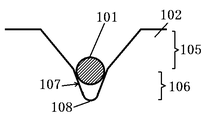
まず、ワイヤーガイドの溝の横断面構造について、図1を用いて、本明細書で使用する用語を定義しながら説明する。図1に示すワイヤーガイドは、本発明のワークの切断方法及びワークの切断装置に用いるワイヤーガイドの、未使用の状態における典型例でもある。
ワイヤーガイドの溝の横断面形状は、図1に示すように、少なくとも、ワイヤーガイドの外表面側に位置し、対向する溝壁が第1の開き角度(θ1)を有する溝上部と、該溝上部の下に位置し、対向する溝壁が第2の開き角度(θ2)を有する溝下部と、前記溝の下端に位置する溝底部とを備えている。つまり、断面視(横断面)において、開き角度を2つ以上有する、二段階以上の構造である。例えば、二段階の構造の場合、溝上部が一段目溝、溝下部が二段目溝となり、溝の深さ方向に形状が変化するものである。
ここで、溝上部の第1の開き角度(θ1)と、第2の開き角度(θ2)を有する溝下部とは、θ1>θ2の関係にある。このような関係にあるワイヤーガイドを使用することで、ワイヤーの引き渡し等の作業性の向上と、ワイヤーの保持効果とを両立することができる。
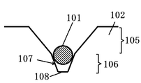
さらに、本発明に係るワークの切断装置において、図1,2に示すように、ワイヤー101とワイヤーガイド102は、ワイヤーガイド102の溝の溝間口の溝幅、すなわち、溝下部の溝幅の最大値(W0,max)が、ワイヤー101のワイヤー径(φ0)以上であり、ワイヤーガイド溝の溝下部の溝幅の最小値(W0,min)が、ワイヤーのワイヤー径(φ0)未満の関係にあり、ワイヤーが溝上部105の下部に位置する溝下部106の溝壁107に接するように設置されたときに、例えば、図2に示すように、ワイヤー101は、溝上部105の下に位置する溝下部106の側壁107に接し、かつ、ワイヤー101とワイヤーガイド102の溝底部108とが接触しないものである。つまり、未使用のワイヤーガイド102の溝内に未使用のワイヤー101を設置したときに、ワイヤー101は溝下部106に嵌った状態で、ワイヤーガイド102の溝底部108に接触せずに浮いた状態にある。
このようにワイヤー101をワイヤーガイド102の溝内に設置すると、ワイヤーガイド102の溝下部内でのワイヤーの横方向の遊びが少なくなり、その結果、ワイヤー101の横方向の振動を抑制することができ、切断速度を低下せずとも、ワークの切断装置の使用開始直後から(使用期間の初期から)、Warp値を安定して低くできる切断装置となる。
なお、上述のようにワイヤー101をワイヤーガイド102の溝内に設置して、ワイヤーソーの運転を開始した場合、ワークの切断(ワイヤーソーの運転)の進行に伴い、ワイヤー101はワイヤーガイド102の溝の側壁107を削りながら、溝底部108に近づいていく。そして、ワークの切断(ワイヤーソーの運転)開始から一定の時間が経過したときに、ワイヤー101がワイヤーガイド102の溝底部108に接触し、溝底部108を削っていく。この場合、溝の側壁107との溝底部108を削り、ワイヤー形状に合わせた溝形状を自成しながら進んでいくため、ワイヤー101の横方向の振動は抑制された状態がより安定的に維持され、したがって、Warp値の悪化は起こらない。
但し、ワイヤーガイドライフの終期まで、ワイヤー101がワイヤーガイド102の溝底部に接触しないような構造に設計することによっても、本発明の効果が発揮されることは言うまでもない。本発明者の調査によれば、使用する材質にもよるが、ワイヤー101は使用に伴い、概ね1割程度、ワイヤー径が細くなる傾向がある。このようなことを加味して、溝形状とワイヤー径(φ0)の関係を設定することが可能である。
ここで、ワイヤーガイド102の溝底部108の横断面形状は、特に限定されず、円弧状、V字状又は平坦な形状とすることができる。このようなワイヤーガイド102にワイヤー101を設置した例を図2-4に示す。なお、図2で説明した事項については、以下の図3-6の説明では適宜省略する。また、図3-6では、1つの溝についてのみ示す。
上述のような形状の溝は、比較的容易(低コスト)かつ高精度で作製でき、低コストでワイヤー101とワイヤーガイド102の溝底部との接触を防止できる。特に、図3のように溝底部108の横断面形状を円弧状とし、その曲率半径Rを、ワイヤーの半径未満としたり、図2のように溝底部108の横断面形状をV字状(すなわち、R=0ともいえる)とすれば、より確実に、設置時からワイヤーガイドライフの初期における、ワイヤー101とワイヤーガイド102の溝底部108との接触を防止できるため、好ましい。さらに、図4に示すように、溝下部106の溝幅の最小値がワイヤー径未満とし、溝底部108にワイヤーを接触させないようにできれば、溝底部108は平坦であってもよい。
また、ワイヤーガイドは、複数の溝における溝下部の溝幅の最大値(W0,max)、及び/又は、第2の開き角度(θ2)を、ワイヤーの進行方向に向けて変化したものとすることができる。上述したように、ワイヤーは使用により線幅が10%程度細くなる傾向がある。このため、ワイヤーにおける切断処理歴が長い部分では、未使用の部分や切断処理歴の短い部分より細くなる。このように、使用中のワイヤーの線幅は、ワイヤーの部分によって異なることがあるため、ワイヤーガイドを、複数の溝の形状を上記のようにワイヤーの進行方向に向けて変化したものとすれば、ワイヤーガイドライフの初期における、ワイヤーとワイヤーガイドの溝底部との非接触状態を、安定して実現できるものとなる。
ワイヤーガイド102の溝における、溝上部の第1の開き角度(θ1)は、60~110°とすることが好ましい。このような範囲に設定すれば、ワイヤーの引き渡し作業の作業性がより優れた切断装置となる。また、溝下部の第2の開き角度(θ2)は、20~60°とすることが好ましい。このような範囲に設定すれば、より安定してワイヤーを保持して、低いWarp値のものを製造可能な切断装置となる。
ワイヤーガイド102の溝にワイヤーを設置する場合には、使用開始時に、ワイヤーの上部が溝下部の上端(溝間口)よりも上部に位置するような関係となるように、ワイヤーと溝の形状を設定することが好ましい。このようにすると、ワイヤーガイド102の長寿命化が可能となる。
また、溝下部の溝幅の最大値(W0,max)である、溝下部の溝間口(溝上部と溝下部との境界部)の溝幅と、ワイヤー径(φ0)は、W0,max/φ0=1.01~1.30となるように設定することが好ましい。このような関係とすることで、より確実にワイヤーを溝下部内に設置でき、ワイヤーの横方向振動をより確実に防止できるものとなる。
さらに、溝底部の曲率半径Rと、ワイヤー径(φ0)は、R/φ0を0.5未満の範囲となるように設定することが好ましい。このような関係とすることで、切断初期において、ワイヤーとワイヤーガイド102の溝底部108との非接触状態を、より安定して確実に実現できるものとなる。
ワイヤーガイド102としては、鉄鋼製円筒の周囲にポリウレタン(エステル系、エーテル系)等の樹脂を圧入したものを好適に用いることができる。また、ワークの切断装置としては、遊離砥粒型、固定砥粒型のいずれの装置であっても適用可能である。
上述のワイヤーガイド溝の溝形状の図示例として、溝上部と溝下部との接続部で、頂点を有する形状が示されているが、滑らかに接続されていてもよい。
次に、本発明に係るワークの切断方法について説明する。上述のワークの切断装置を用いてワークを切断することにより、生産能力(スループット)の低下を抑制しながら、ワイヤーガイドの使用初期(使用開始直後)から良好で、かつ、安定したワーク形状(Warp値)を得ることができ、ワイヤーガイドのライフに依存しないワークの品質を得ることができる。
まず、ワークの切断の開始前に、切断装置の設定を行う。互いの回転軸方向が平行となるように複数設置した円筒状のワイヤーガイドにワイヤーを螺旋状に巻掛けてワイヤー列を形成する。
上述したように、未使用のワイヤーガイド102における溝の横断面形状は、少なくとも、ワイヤーガイド外表面側に位置し、対向する溝壁107が第1の開き角度(θ1)を有する溝上部105と、該溝上部105の下に位置し、対向する溝壁107が第2の開き角度(θ2)を有する溝下部106と、溝の下端に位置する溝底部108とを備え、第1の開き角度(θ1)と第2の開き角度(θ2)とが、θ1>θ2の関係にある。また、未使用のワイヤーガイドの溝下部106の溝幅の最大値(W0,max)が、未使用のワイヤー101のワイヤー径(φ0)以上であり、未使用のワイヤーガイド102の溝下部106の溝幅の最小値(W0,min)が、未使用のワイヤー101のワイヤー径(φ0)未満の関係(W0,min<φ0≦W0,max)にある。このような関係にある、未使用のワイヤー101と未使用のワイヤーガイド102とを使用し、未使用のワイヤー101が、未使用のワイヤーガイド102の溝下部106の溝壁107に接し、かつ、溝底部108に接触しない状態で設置し、ワイヤーが溝底部108に接触しない状態で、ワークの切断を開始することで、生産能力(スループット)の低下を抑制しながら、ワイヤーガイド102の使用初期(使用開始直後)から良好かつ安定したワーク形状(Warp値)を得ることができ、ワイヤーガイド102のライフに依存しないワークの品質を得ることができる。
上述のようにワイヤーをワイヤーガイド溝内に設置して、ワイヤーソーの運転を開始すると、運転開始直後は、ワイヤーが溝下部の側壁により支持(保持)された状態であり、ワークの切断(ワイヤーソーの運転)の進行に伴い、ワイヤーはワイヤーガイド溝の側面を削りながら溝底部に近づいていき、ワイヤー径に応じた最適溝形状を自成しながら切断が進行していく。そして、ワークの切断(ワイヤーソーの運転)開始から一定の時間が経過すると、ワイヤーはワイヤーガイドの溝底部に接触し、溝底部を削っていく。このようにワイヤーがワイヤーガイドの溝底部に接触した場合であっても、溝を削りながら進んでいくため、ワイヤーの横方向の振動は抑制されたままであり、したがって、Warp値の悪化は起こらない。
また、装置について説明したように、ワイヤーガイドとして、複数の溝の形状を上記のようにワイヤーの進行方向に向けて変化したものを使用してワークを切断すれば、ワイヤーガイドライフの初期における、ワイヤーとワイヤーガイドの溝底部との非接触状態を、安定して実現できる。また、切断速度を落とす必要もないため、生産能力の低下を抑制できる。
以下、実施例を挙げて本発明について詳細に説明するが、これは本発明を限定するものではない。
(実施例)
未使用(新品)のワイヤーガイドとして、溝上部の第1開き角度(θ1)が90度、溝下部の第2開き角度(θ2)が40度、溝下部の深さが130μm、溝下部の溝間口の溝幅(W0,max)が140μm、溝底部の曲率半径Rが0.030mmの、各溝形状パラメータを有するものを使用した。このようなワイヤーガイドに、0.13mmのワイヤー径(φ0)を有する未使用(新品)のワイヤーを設置すると、ワイヤーは、ワイヤーガイドの溝下部の溝壁に接し、かつ、溝底部に接触しない状態で設置された(図3参照)。
未使用(新品)のワイヤーガイドとして、溝上部の第1開き角度(θ1)が90度、溝下部の第2開き角度(θ2)が40度、溝下部の深さが130μm、溝下部の溝間口の溝幅(W0,max)が140μm、溝底部の曲率半径Rが0.030mmの、各溝形状パラメータを有するものを使用した。このようなワイヤーガイドに、0.13mmのワイヤー径(φ0)を有する未使用(新品)のワイヤーを設置すると、ワイヤーは、ワイヤーガイドの溝下部の溝壁に接し、かつ、溝底部に接触しない状態で設置された(図3参照)。
次に、直径が200mmのシリコン単結晶インゴットを切断対象のワークとして用い、ワイヤーソー装置を用いて切断加工を行い、切断して得たシリコンウェーハの形状測定を行い、Warp値を算出した。
(比較例1)
未使用(新品)のワイヤーガイドとして、溝の横断面形状がV溝1段であり、溝の開き角度が90度、ワイヤーガイド外表面での溝幅が0.6mm(600μm)のものを使用した点を除いて、実施例1と同じ条件で切断加工、及び、切断して得たシリコンウェーハの形状測定を行った。比較例1で用いたワイヤーガイドにワイヤーを設置すると、図5に示すような状態となった。ワイヤーを溝内に設置した時点で、ワイヤーは溝内で横方向に、いわゆる遊びを有していた。
未使用(新品)のワイヤーガイドとして、溝の横断面形状がV溝1段であり、溝の開き角度が90度、ワイヤーガイド外表面での溝幅が0.6mm(600μm)のものを使用した点を除いて、実施例1と同じ条件で切断加工、及び、切断して得たシリコンウェーハの形状測定を行った。比較例1で用いたワイヤーガイドにワイヤーを設置すると、図5に示すような状態となった。ワイヤーを溝内に設置した時点で、ワイヤーは溝内で横方向に、いわゆる遊びを有していた。
(比較例2)
未使用(新品)のワイヤーガイドとして、溝上部の第1開き角度(θ1)が90度、溝下部の第2開き角度(θ2)が40度、溝下部の深さが130μm、溝下部の溝間口の溝幅(W0,max)が190μm、溝底部の曲率半径Rが0.065mmの、各溝形状パラメータを有するものを使用した。このようなワイヤーガイドに、0.13mmのワイヤー径(φ0)を有する新品のワイヤーを設置すると、ワイヤーとワイヤーガイドの溝底部が接触した状態となった(図6参照)。ワイヤーを溝内に設置した時点で、ワイヤーは溝内で横方向に、いわゆる遊びを有していた。これ以外は、実施例1と同じ条件で切断加工、及び、切断して得たシリコンウェーハの形状測定を行った。
未使用(新品)のワイヤーガイドとして、溝上部の第1開き角度(θ1)が90度、溝下部の第2開き角度(θ2)が40度、溝下部の深さが130μm、溝下部の溝間口の溝幅(W0,max)が190μm、溝底部の曲率半径Rが0.065mmの、各溝形状パラメータを有するものを使用した。このようなワイヤーガイドに、0.13mmのワイヤー径(φ0)を有する新品のワイヤーを設置すると、ワイヤーとワイヤーガイドの溝底部が接触した状態となった(図6参照)。ワイヤーを溝内に設置した時点で、ワイヤーは溝内で横方向に、いわゆる遊びを有していた。これ以外は、実施例1と同じ条件で切断加工、及び、切断して得たシリコンウェーハの形状測定を行った。
なお、参考のため、切断加工条件(上述の条件も含む)の代表値を、表1に示す。

図7に、ウェーハのWarp値の推移を示す。横軸は、ワイヤーガイドのライフの初期から一定期間の処理バッチを抽出した。縦軸はWarp値を示す。プロットは、10バッチごとのWarp値の平均値を1プロットとした。また、実施例と比較例1,2を比較するために、比較例1の切断加工初期から30バッチの平均値を基準の1として、相対値で比較した。図7に示すように、比較例1ではWarp値が低く安定するまでの切断加工処理バッチが最も多くなることがわかる。
図8は、図7における、ワイヤーガイドライフ初期の3プロット(30バッチ分)の範囲を拡大した図である。図8に示すように、実施例ではごく初期からWarp値が低く安定する結果が得られた。また、比較例2では、図7に示すように、比較例1よりは早い段階で安定化したものの、図8に示すようにごく初期ではWarp値が高くばらつく結果となった。図8に示したごく初期の30バッチ分のデータをもとに、ワイヤーガイドライフ初期(30バッチ)の比較を行ったところ、実施例においては、Warp値、ばらつきともに、比較例1,2より安定して高品質なものが得られた。
以上に述べた実施例、比較例1,2の条件と、評価結果を、表2にまとめた。

図7に示されるように、実施例においては、使用開始時から、ワイヤーガイドの溝下部内にワイヤーが適切に嵌まり込み、ワイヤーの遊びがなくなるため、Warp値が最初から安定するものと考えられる。一方、実施例と比較例1,2すべてにおいて、最終的にはロット間やロット内のWarp値が低く安定する。これは、ワイヤーガイド溝の側面(側壁)及び溝底面が、ワイヤーの走行により、徐々に溝底部に向かって研削され、溝の側面(側壁)及び溝底面形状がワイヤー形状になじんでいくためであると考えられる。比較例2においては、ワイヤーガイドの溝下部内にワイヤーが設けられるものの、溝底部に接触するように設置されているため、ワイヤーの遊びを排除できず、実施例に比べ、ごく初期の数十バッチでWarp値が乱れたものと思われる。
既に述べたように、ワイヤーは使用することで摩耗し細くなるため、溝間口の溝幅(W0,max)とワイヤー径(φ)との比は、使用状態によって変わる。ワイヤーをワイヤーガイド溝に設置するときに、ワイヤーライフのごく初期における溝底部とワイヤーとの非接触状態をより安定して維持するためには、ワイヤー径(φ)の変動を加味して、未使用のワイヤーガイド溝の溝間口の溝幅(W0,max)との関係を設定することが好ましい。そこで、実施例と比較例2について、未使用のワイヤーガイドの溝の溝間口の溝幅(W0,max)とワイヤー径(φ)との比(溝間口/ワイヤー径=W0,max/φ)、及び、未使用のワイヤーガイドの溝の溝底部の曲率半径(R)とワイヤー径(φ)との比(溝間口/ワイヤー径=R/φ)を調査した。その結果を表3に示す。
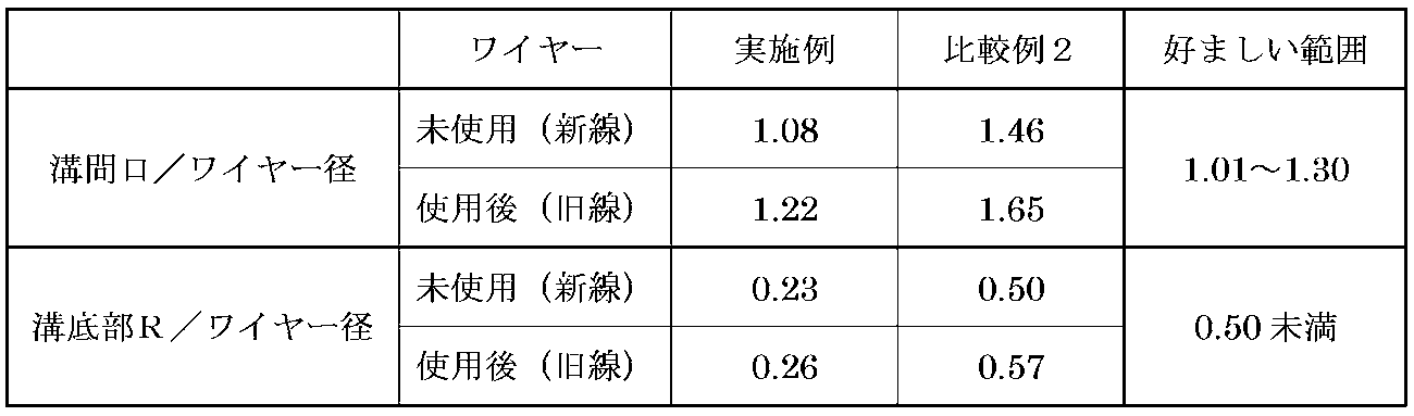
表3に示すように、ワイヤー径(φ0)を基準としたときに、ワイヤーガイドの溝の溝間口の溝幅(W0,max)は、1.01~1.30の範囲に設定し、溝の溝底部の曲率半径Rは、0.5未満の範囲に設定することが好ましいことがわかった。
例えば、既に述べたようにワイヤーガイドとして、複数の溝の形状を上記のようにワイヤーの進行方向に向けて徐々に溝の溝間口の溝幅(W0,max)を狭くなるように変化させる場合に、上記の範囲内で設定することが有効である。
以上のとおり、本発明の実施例によれば、ワイヤーガイド使用開始直後からWarpを安定して良好なレベルとでき、ワイヤーガイドライフに依存しないワーク形状品質を得ることが可能となるとともに、切断速度(生産能力)を落すことなくワーク形状品質を維持できることがわかった。
なお、本発明は、上記実施形態に限定されるものではない。上記実施形態は例示であり、本発明の特許請求の範囲に記載された技術的思想と実質的に同一な構成を有し、同様な作用効果を奏するものは、いかなるものであっても本発明の技術的範囲に包含される。
Claims (8)
- 互いの回転軸方向が平行となるように複数設置した円筒状のワイヤーガイドにワイヤーを螺旋状に巻掛けてワイヤー列を形成し、前記ワイヤーを軸方向に走行させながら、ワークを前記ワイヤー列に押し当てて、同時に複数箇所でウェーハ状に切断する方法であって、
前記ワイヤーガイドは、外表面に、回転方向に沿って所定のピッチで形成された複数の溝を有し、
未使用の前記ワイヤーガイドにおける前記溝の横断面形状は、少なくとも、ワイヤーガイド外表面側に位置し、対向する溝壁が第1の開き角度(θ1)を有する溝上部と、該溝上部の下に位置し、対向する溝壁が第2の開き角度(θ2)を有する溝下部と、前記溝の下端に位置する溝底部とを備え、
前記第1の開き角度(θ1)と前記第2の開き角度(θ2)とが、θ1>θ2の関係にあり、
前記未使用のワイヤーガイドの前記溝下部の溝幅の最大値(W0,max)が、未使用のワイヤーのワイヤー径(φ0)以上であり、前記未使用のワイヤーガイドの前記溝下部の前記溝幅の最小値(W0,min)が、前記未使用のワイヤーのワイヤー径(φ0)未満の関係にある、前記未使用のワイヤーと前記未使用のワイヤーガイドを用い、
前記未使用のワイヤーを、前記未使用のワイヤーガイドの前記溝下部の前記溝壁に接し、かつ、前記溝底部に接触しない状態で設置し、
前記ワイヤーが前記溝底部に接触しない状態で、前記ワークの切断を開始することを特徴とするワークの切断方法。 - 前記溝底部の横断面形状が、円弧状、V字状又は平坦であるワイヤーガイドを用いることを特徴とする請求項1に記載のワークの切断方法。
- 前記ワークの切断の進行に伴い、前記ワイヤーが前記溝壁を切削することを特徴とする請求項1又は請求項2に記載のワークの切断方法。
- 前記ワークの切断の進行に伴い、前記ワイヤーが前記溝底部に接触し、前記溝底を切削することを特徴とする請求項1から請求項3のいずれか一項に記載のワークの切断方法。
- 前記未使用のワイヤーガイドとして、前記複数の溝における前記溝下部の溝幅の最大値(W0,max)、及び/又は、第2の開き角度(θ2)を、前記ワイヤーの進行方向に向けて変化させたものを用いることを特徴とする請求項1から請求項4のいずれか一項に記載のワークの切断方法。
- 互いの回転軸方向が平行となるように所定間隔を隔てて配置され、外表面にそれぞれ所定のピッチで溝が形成された複数の円筒状のワイヤーガイドと、
前記ワイヤーガイドの溝に所定のピッチで螺旋状に巻き掛けられたワイヤーにより形成されるワイヤー列と、
を具備し、
前記ワイヤーガイドを回転させることで前記ワイヤーを軸方向に走行させながら、ワークを前記ワイヤー列に押し当てて、同時に複数箇所でウェーハ状に切断する切断装置であって、
前記ワイヤーガイドにおける前記溝の横断面形状は、少なくとも、ワイヤーガイド外表面側に位置し、対向する溝壁が第1の開き角度(θ1)を有する溝上部と、該溝上部の下に位置し、対向する溝壁が第2の開き角度(θ2)を有する溝下部と、前記溝の下端に位置する溝底部とを備え、
前記第1の開き角度(θ1)と前記第2の開き角度(θ2)とが、θ1>θ2の関係にあるものであり、
前記ワイヤーと前記ワイヤーガイドは、前記ワイヤーガイドの前記溝下部の溝幅の最大値(W0,max)が、前記ワイヤーのワイヤー径(φ0)以上であり、前記ワイヤーガイドの前記溝下部の前記溝幅の最小値(W0,min)が、前記ワイヤーのワイヤー径(φ0)未満の関係にあり、
前記ワイヤーが前記溝下部の前記溝壁に接するように設置されたときに、前記ワイヤーと前記ワイヤーガイドの前記溝底部とが接触しないものであることを特徴とするワークの切断装置。 - 前記ワイヤーガイドの前記溝底部の横断面形状が、円弧状、V字状又は平坦であることを特徴とする請求項6に記載のワークの切断装置。
- 前記ワイヤーガイドは、前記複数の溝における前記溝下部の溝幅の最大値(W0,max)、及び/又は、第2の開き角度(θ2)が、前記ワイヤーの進行方向に向けて変化したものであることを特徴とする請求項6又は請求項7のいずれか一項に記載のワークの切断装置。
Priority Applications (2)
| Application Number | Priority Date | Filing Date | Title |
|---|---|---|---|
| KR1020217023146A KR102741189B1 (ko) | 2019-02-13 | 2020-01-15 | 워크의 절단방법 및 워크의 절단장치 |
| CN202080008473.XA CN113272101B (zh) | 2019-02-13 | 2020-01-15 | 工件的切断方法及工件的切断装置 |
Applications Claiming Priority (2)
| Application Number | Priority Date | Filing Date | Title |
|---|---|---|---|
| JP2019023448A JP6627002B1 (ja) | 2019-02-13 | 2019-02-13 | ワークの切断方法及びワークの切断装置 |
| JP2019-023448 | 2019-02-13 |
Publications (1)
| Publication Number | Publication Date |
|---|---|
| WO2020166259A1 true WO2020166259A1 (ja) | 2020-08-20 |
Family
ID=69101061
Family Applications (1)
| Application Number | Title | Priority Date | Filing Date |
|---|---|---|---|
| PCT/JP2020/001085 Ceased WO2020166259A1 (ja) | 2019-02-13 | 2020-01-15 | ワークの切断方法及びワークの切断装置 |
Country Status (5)
| Country | Link |
|---|---|
| JP (1) | JP6627002B1 (ja) |
| KR (1) | KR102741189B1 (ja) |
| CN (1) | CN113272101B (ja) |
| TW (1) | TWI858010B (ja) |
| WO (1) | WO2020166259A1 (ja) |
Families Citing this family (3)
| Publication number | Priority date | Publication date | Assignee | Title |
|---|---|---|---|---|
| CN115701381A (zh) * | 2021-08-02 | 2023-02-10 | 天津市环欧半导体材料技术有限公司 | 一种太阳能硅片线切机用槽轮槽型及槽轮 |
| WO2023171902A1 (ko) * | 2022-03-11 | 2023-09-14 | 신정훈 | 단층 권취형 멀티 케이블 릴 및 이를 이용한 공중설치기기 |
| KR102714174B1 (ko) * | 2022-03-11 | 2024-10-07 | 신정훈 | 단층 권취형 멀티 케이블 릴 및 이를 이용한 공중설치기기 |
Citations (6)
| Publication number | Priority date | Publication date | Assignee | Title |
|---|---|---|---|---|
| JPH0970821A (ja) * | 1995-09-06 | 1997-03-18 | Seiko Epson Corp | ワイヤー式加工切断装置 |
| JP2001079748A (ja) * | 1999-09-09 | 2001-03-27 | Nippei Toyama Corp | ワイヤソーの加工用ローラ |
| EP2347845A1 (de) * | 2010-01-26 | 2011-07-27 | Schott Solar AG | Drahtführungsrolle zur Verwendung in Drahtsägen |
| CN103395131A (zh) * | 2013-08-02 | 2013-11-20 | 苏州协鑫光伏科技有限公司 | 多线切割机导轮线槽及其加工方法 |
| JP5362053B2 (ja) * | 2012-01-31 | 2013-12-11 | 株式会社ノリタケカンパニーリミテド | ワイヤーソー用ローラー |
| JP2014161924A (ja) * | 2013-02-21 | 2014-09-08 | Toyo Advanced Technologies Co Ltd | ワイヤソー |
Family Cites Families (7)
| Publication number | Priority date | Publication date | Assignee | Title |
|---|---|---|---|---|
| JP3656317B2 (ja) | 1996-03-27 | 2005-06-08 | 信越半導体株式会社 | ワイヤソーによるワーク切断方法及び装置 |
| JP4816511B2 (ja) | 2007-03-06 | 2011-11-16 | 信越半導体株式会社 | 切断方法およびワイヤソー装置 |
| TW201304924A (zh) * | 2011-07-22 | 2013-02-01 | Sino American Silicon Prod Inc | 線切割裝置的主輪結構、其製作方法及線切割裝置 |
| JP5881378B2 (ja) * | 2011-11-09 | 2016-03-09 | 金井 宏彰 | ワイヤーソーのローラ |
| JP5672224B2 (ja) * | 2011-12-19 | 2015-02-18 | 住友金属鉱山株式会社 | 溝付きローラー及びこれを用いたワイヤーソー |
| DE102013225104B4 (de) * | 2013-12-06 | 2019-11-28 | Siltronic Ag | Verfahren zum Abtrennen von Scheiben von einem Werkstück mittels einer Drahtsäge |
| JP6402700B2 (ja) * | 2015-10-20 | 2018-10-10 | 信越半導体株式会社 | ワークの切断方法及びワイヤソー |
-
2019
- 2019-02-13 JP JP2019023448A patent/JP6627002B1/ja active Active
-
2020
- 2020-01-15 KR KR1020217023146A patent/KR102741189B1/ko active Active
- 2020-01-15 WO PCT/JP2020/001085 patent/WO2020166259A1/ja not_active Ceased
- 2020-01-15 CN CN202080008473.XA patent/CN113272101B/zh active Active
- 2020-02-07 TW TW109103781A patent/TWI858010B/zh active
Patent Citations (6)
| Publication number | Priority date | Publication date | Assignee | Title |
|---|---|---|---|---|
| JPH0970821A (ja) * | 1995-09-06 | 1997-03-18 | Seiko Epson Corp | ワイヤー式加工切断装置 |
| JP2001079748A (ja) * | 1999-09-09 | 2001-03-27 | Nippei Toyama Corp | ワイヤソーの加工用ローラ |
| EP2347845A1 (de) * | 2010-01-26 | 2011-07-27 | Schott Solar AG | Drahtführungsrolle zur Verwendung in Drahtsägen |
| JP5362053B2 (ja) * | 2012-01-31 | 2013-12-11 | 株式会社ノリタケカンパニーリミテド | ワイヤーソー用ローラー |
| JP2014161924A (ja) * | 2013-02-21 | 2014-09-08 | Toyo Advanced Technologies Co Ltd | ワイヤソー |
| CN103395131A (zh) * | 2013-08-02 | 2013-11-20 | 苏州协鑫光伏科技有限公司 | 多线切割机导轮线槽及其加工方法 |
Also Published As
| Publication number | Publication date |
|---|---|
| TW202039149A (zh) | 2020-11-01 |
| CN113272101B (zh) | 2023-05-05 |
| JP6627002B1 (ja) | 2019-12-25 |
| TWI858010B (zh) | 2024-10-11 |
| JP2020131299A (ja) | 2020-08-31 |
| KR20210126002A (ko) | 2021-10-19 |
| KR102741189B1 (ko) | 2024-12-10 |
| CN113272101A (zh) | 2021-08-17 |
Similar Documents
| Publication | Publication Date | Title |
|---|---|---|
| JP6366783B2 (ja) | ワークピースから特に均一な厚さの多数のスライスを同時に切り出すための方法 | |
| CN110430958B (zh) | 线锯、导线辊与用于从料锭同时切割多个晶片的方法 | |
| EP0798091B1 (en) | Wire saw and method of slicing a cylindrical workpiece, e.g. an ingot | |
| KR101880518B1 (ko) | 실리콘 웨이퍼의 제조 방법 | |
| JP6627002B1 (ja) | ワークの切断方法及びワークの切断装置 | |
| KR102103330B1 (ko) | 잉곳의 절단방법 및 와이어 쏘 | |
| JP6589744B2 (ja) | ワークの切断方法 | |
| JP7797541B2 (ja) | ワークピースから複数のディスクを同時に切り出すための方法 | |
| CN110461543A (zh) | 工件的切断方法 | |
| KR101693065B1 (ko) | 금속 선재의 제조 방법 | |
| JP2003127058A (ja) | ワイヤソー | |
| WO2016117294A1 (ja) | ワークの切断方法 | |
| TWI817164B (zh) | 從工件同時切割多個切片的方法和設備 | |
| JP6395497B2 (ja) | ウェーハの製造方法 | |
| JP2011230274A (ja) | ソーワイヤおよびそれを用いたシリコンインゴットの切断方法 | |
| CN115609775A (zh) | 线切割单元、设备、硅片及其制造方法 | |
| CN108778623B (zh) | 线锯装置的制造方法及线锯装置 | |
| JP2010131715A (ja) | ソーワイヤ、ワイヤソーおよびそれを用いた半導体ブロックの切断方法、並びに、半導体ウエハの製造方法および半導体ウエハ | |
| JP2007276048A (ja) | ワイヤによるワークの切断方法 | |
| JP2000233356A (ja) | ワイヤソーの切断方法及びワイヤ | |
| JP4977910B2 (ja) | ワイヤによるワークの切断方法 | |
| JP7145045B2 (ja) | ワイヤソーの制御方法 | |
| JP2013233606A (ja) | ワイヤソー装置及び切断加工方法 | |
| JP2000108010A (ja) | ワイヤソ―の切断方法 |
Legal Events
| Date | Code | Title | Description |
|---|---|---|---|
| 121 | Ep: the epo has been informed by wipo that ep was designated in this application |
Ref document number: 20755538 Country of ref document: EP Kind code of ref document: A1 |
|
| ENP | Entry into the national phase |
Ref document number: 20217023146 Country of ref document: KR Kind code of ref document: A |
|
| NENP | Non-entry into the national phase |
Ref country code: DE |
|
| 122 | Ep: pct application non-entry in european phase |
Ref document number: 20755538 Country of ref document: EP Kind code of ref document: A1 |