WO2020162636A1 - 入力装置及び画像形成装置 - Google Patents
入力装置及び画像形成装置 Download PDFInfo
- Publication number
- WO2020162636A1 WO2020162636A1 PCT/JP2020/005013 JP2020005013W WO2020162636A1 WO 2020162636 A1 WO2020162636 A1 WO 2020162636A1 JP 2020005013 W JP2020005013 W JP 2020005013W WO 2020162636 A1 WO2020162636 A1 WO 2020162636A1
- Authority
- WO
- WIPO (PCT)
- Prior art keywords
- cable
- image forming
- unit
- forming apparatus
- key
- Prior art date
- Legal status (The legal status is an assumption and is not a legal conclusion. Google has not performed a legal analysis and makes no representation as to the accuracy of the status listed.)
- Ceased
Links
Images



Classifications
-
- H—ELECTRICITY
- H04—ELECTRIC COMMUNICATION TECHNIQUE
- H04N—PICTORIAL COMMUNICATION, e.g. TELEVISION
- H04N1/00—Scanning, transmission or reproduction of documents or the like, e.g. facsimile transmission; Details thereof
- H04N1/00127—Connection or combination of a still picture apparatus with another apparatus, e.g. for storage, processing or transmission of still picture signals or of information associated with a still picture
- H04N1/00326—Connection or combination of a still picture apparatus with another apparatus, e.g. for storage, processing or transmission of still picture signals or of information associated with a still picture with a data reading, recognizing or recording apparatus, e.g. with a bar-code apparatus
-
- B—PERFORMING OPERATIONS; TRANSPORTING
- B41—PRINTING; LINING MACHINES; TYPEWRITERS; STAMPS
- B41J—TYPEWRITERS; SELECTIVE PRINTING MECHANISMS, i.e. MECHANISMS PRINTING OTHERWISE THAN FROM A FORME; CORRECTION OF TYPOGRAPHICAL ERRORS
- B41J29/00—Details of, or accessories for, typewriters or selective printing mechanisms not otherwise provided for
-
- G—PHYSICS
- G03—PHOTOGRAPHY; CINEMATOGRAPHY; ANALOGOUS TECHNIQUES USING WAVES OTHER THAN OPTICAL WAVES; ELECTROGRAPHY; HOLOGRAPHY
- G03G—ELECTROGRAPHY; ELECTROPHOTOGRAPHY; MAGNETOGRAPHY
- G03G21/00—Arrangements not provided for by groups G03G13/00 - G03G19/00, e.g. cleaning, elimination of residual charge
- G03G21/16—Mechanical means for facilitating the maintenance of the apparatus, e.g. modular arrangements
-
- G—PHYSICS
- G06—COMPUTING OR CALCULATING; COUNTING
- G06F—ELECTRIC DIGITAL DATA PROCESSING
- G06F3/00—Input arrangements for transferring data to be processed into a form capable of being handled by the computer; Output arrangements for transferring data from processing unit to output unit, e.g. interface arrangements
- G06F3/01—Input arrangements or combined input and output arrangements for interaction between user and computer
- G06F3/02—Input arrangements using manually operated switches, e.g. using keyboards or dials
- G06F3/0227—Cooperation and interconnection of the input arrangement with other functional units of a computer
-
- H—ELECTRICITY
- H01—ELECTRIC ELEMENTS
- H01H—ELECTRIC SWITCHES; RELAYS; SELECTORS; EMERGENCY PROTECTIVE DEVICES
- H01H9/00—Details of switching devices, not covered by groups H01H1/00 - H01H7/00
- H01H9/02—Bases, casings, or covers
-
- H—ELECTRICITY
- H04—ELECTRIC COMMUNICATION TECHNIQUE
- H04N—PICTORIAL COMMUNICATION, e.g. TELEVISION
- H04N1/00—Scanning, transmission or reproduction of documents or the like, e.g. facsimile transmission; Details thereof
-
- H—ELECTRICITY
- H04—ELECTRIC COMMUNICATION TECHNIQUE
- H04N—PICTORIAL COMMUNICATION, e.g. TELEVISION
- H04N1/00—Scanning, transmission or reproduction of documents or the like, e.g. facsimile transmission; Details thereof
- H04N1/0035—User-machine interface; Control console
- H04N1/00352—Input means
- H04N1/00384—Key input means, e.g. buttons or keypads
-
- H—ELECTRICITY
- H04—ELECTRIC COMMUNICATION TECHNIQUE
- H04N—PICTORIAL COMMUNICATION, e.g. TELEVISION
- H04N1/00—Scanning, transmission or reproduction of documents or the like, e.g. facsimile transmission; Details thereof
- H04N1/0035—User-machine interface; Control console
- H04N1/00405—Output means
- H04N1/00408—Display of information to the user, e.g. menus
- H04N1/00411—Display of information to the user, e.g. menus the display also being used for user input, e.g. touch screen
-
- H—ELECTRICITY
- H04—ELECTRIC COMMUNICATION TECHNIQUE
- H04N—PICTORIAL COMMUNICATION, e.g. TELEVISION
- H04N1/00—Scanning, transmission or reproduction of documents or the like, e.g. facsimile transmission; Details thereof
- H04N1/0035—User-machine interface; Control console
- H04N1/00493—Particular location of the interface or console
Definitions
- the present invention relates to an input device that has a hardware key and is externally attached to an image forming apparatus, and an image forming apparatus to which the input device is externally attached.
- an electrophotographic image forming apparatus has been widely applied as a copying machine, a printer, a facsimile, and a multifunction machine having a plurality of these functions.
- an image forming apparatus in order for the user to input a numerical value such as the number of images formed or a facsimile number, or to input a process such as starting or stopping the image forming process, for example, information is provided on the upper front side of the apparatus main body.
- An operation unit display unit capable of displaying and inputting is provided.
- an operation unit for example, one including a touch panel on which an input key (software key) is displayed on a display screen and a hardware key such as a ten-key pad or a start key and a stop key is widely used.
- the hardware key is arranged, for example, adjacent to the touch panel.
- the image forming apparatus In the image forming apparatus provided with the operation unit, when inputting the number of copies and the destination number (telephone number/FAX number) of a facsimile, for example, a numeric keypad as a software key having a numerical value from 0 to 9 The section is displayed.
- the control unit acquires coordinate data of the portion touched by the user from the touch panel, converts the coordinate data into numerical information, and executes a predetermined operation according to the coordinate data. To do.
- an image forming apparatus has been developed in which an input device (for example, a numeric keypad unit or a full keyboard unit) having a numerical key portion composed of physical hardware keys can be connected externally (special feature. Open 2014-22927).
- an input device for example, a numeric keypad unit or a full keyboard unit
- the user connects the input apparatus externally via a cable and presses down the hardware key of the numerical key section of the input apparatus to input the number of copies and the destination number of the facsimile. You can
- the cable connecting the input device and the image forming apparatus is exposed to the outside of the image forming apparatus. It is easy to interfere with the peripheral devices that are placed. If the cable is exposed, the user may accidentally pull it out.
- the present invention is an input device for external attachment that can be connected to an image forming apparatus by a cable, but can suppress interference with peripheral devices due to the cable being exposed to the outside and erroneous extraction by a user and an image.
- An object is to provide a forming apparatus.
- An input device is an input device that is attached to a mounting portion of an image forming apparatus and is capable of inputting information to the image forming apparatus.
- An opening provided, a main body side cable that is inserted into the opening and exposed to the outside from the housing, and electrically connects the image forming apparatus and the input device, and at least information regarding numerical values
- a numerical key section made of a hardware key capable of inputting the numerical key, wherein the numerical key section is arranged on an upper surface of the housing when the housing is mounted on the image forming apparatus, and the opening is Is provided on the bottom surface of the housing when the housing is mounted on the image forming apparatus.
- the image forming apparatus of the present invention includes an image forming section capable of forming an image, an apparatus main body having the image forming section therein and a mounting section, and provided in the apparatus main body and capable of displaying information.
- the display unit and the input device described above are provided.
- FIG. 5 is an exploded perspective view showing a ten-key unit of the image forming apparatus according to this embodiment.
- the image forming apparatus 1 of the present embodiment includes an image forming apparatus main body (hereinafter referred to as an apparatus main body) 10.
- the apparatus main body 10 includes an image reading unit 20, a sheet feeding unit 21, an image forming unit 22 (see FIG. 3 ), a sheet discharging unit 23 (see FIG. 3 ), a control unit 30 (see FIG. 3 ),
- the operation unit 50 is provided.
- the operation unit 50 is provided above the sheet discharge unit 23 in the vertical direction.
- a sheet as a recording material is one on which a toner image is formed, and specific examples thereof include plain paper, a resin sheet that is a substitute for plain paper, a thick paper, and a sheet for an overhead projector.
- the control unit 30 includes an operation unit input/output circuit (I/F) 35, a network input/output circuit (I/F) 36, a modem 37, an SRAM 38, an RTC 39, and an external unit which are all connected to the system bus 30a. And an input/output circuit (I/F) 40.
- the operation unit input/output circuit 35 transmits image data to the operation unit 50, which will be described later, performs various communications from the operation unit 50, and inputs information input by the user from the operation unit 50 to the CPU 31.
- the network input/output circuit 36 connects to the network 90 and inputs/outputs information.
- the modem 37 is connected to the public line 91, functions as a facsimile communication unit capable of transmitting and receiving facsimiles, and inputs and outputs information. Accordingly, the control unit 30 can communicate with another connected PC or server under the instruction of the CPU 31 via the network 90 by the network input/output circuit 36 or via the public line 91 by the modem 37. .. That is, the image forming apparatus 1 inputs and outputs image information and device information by connecting to the network 90 and the public line 91.
- a USB plug 78 of a main body side cable 76 of the numeric keypad unit 70 is coupled and connected to the USB connector 40a.
- the control board 30c is not limited to this arrangement and may be provided on the rear side B (back side) of the image forming apparatus 1. In the case of this configuration, only the USB connector 40a may be provided on the front side F and the USB connector 40a and the control board 30c may be connected by a cable.
- the control unit 30 has an image bus input/output circuit (I/F) 41.
- the image bus input/output circuit 41 is a bus bridge that connects the system bus 30a and the image bus 30b that transfers image data at high speed, and converts the data structure.
- the image bus 30b is composed of, for example, a PCI bus or IEEE1394.
- the control unit 30 includes a device input/output circuit (I/F) 42, a RIP unit 43, a scanner image processing unit 44, a printer image processing unit 45, and a cryptographic processing unit 46, all of which are connected to the image bus 30b. , And a decoding processing unit 47.
- the device input/output circuit 42 connects the image reading unit 20 and the image forming unit 22 to the control unit 30 and performs synchronous and asynchronous conversion of image data.
- the RIP unit 43 is a raster image processor and develops PDL data into a bitmap image.
- the scanner image processing unit 44 corrects, processes, and edits input image data.
- the printer image processing unit 45 performs printer correction, resolution conversion, and the like on print output image data.
- the encryption processing unit 46 performs an encryption process on input data including image data.
- the decryption processing unit 47 performs a decryption process on encrypted data.
- the operation unit 50 is for an operator to perform an operation, and includes a display unit 51 that displays various types of information and an input unit 52 that allows the operator to perform operation input.
- the operation unit 50 has, for example, a touch input type panel surface 57 in which a display unit 51 which is a liquid crystal module and an input unit 52 which is a touch panel module are integrated.
- a start key capable of inputting information for starting a predetermined process or a software key capable of inputting a numerical value of 0 to 9 can be displayed on the display unit 51, and information can be input by the input unit 52. is there.
- the operation unit 50 is an example of an operation panel.
- the operation unit 50 is provided on the operation surface 11 of the apparatus body 10. Further, as shown in FIG. 1, the operation unit 50 is provided on the front side F of the central portion of the image forming apparatus 1 in the front-rear direction.
- the operation unit 50 is formed in, for example, a rectangular flat plate shape, and the panel surface 57 configured by stacking the input unit 52 on the display unit 51 (see FIG. 3) faces the upper side U, and the device main body 10 is provided. It is fixedly installed in.
- the software key displayed on the panel surface 57 is an input key for detecting the key input by touching each display portion.
- the shape of the operation unit 50 is not limited to the rectangular flat plate shape, and may be another shape.
- the orientations of the display unit 51 and the input unit 52 are not limited to the upper side U and may be in other directions. It may be provided so as to be changeable. ⁇ Numpad unit>
- a ten-key unit 70 is installed on the right side of the operation unit 50.
- the ten-key unit 70 is attached to the image forming apparatus 1 having the operation section 50 capable of inputting information, and information can be input to the image forming apparatus 1 separately from the operation section 50.
- settings such as density and size relating to image formation are input from the operation unit 50, and the number of image formation and facsimile destination number are input from the ten-key unit 70. Enter the numerical value such as.
- the ten-key pad refers to ten numeric keys from 0 to 9, twelve numeric keys with “*” and “#” added to the numeric keys, and four arithmetic operations to the numeric keys. It is a concept including any of the cases where about 20 keys including children and "NumLock" are shown.
- the numeric keypad unit 70 has a housing 71, a top cover 72 provided on the top surface of the housing 71, and operation keys (numerical key portion) 100 provided on the top cover 72.
- the operation keys 100 are arranged on the upper surface (upper surface of the housing) 72a of the upper surface cover 72 of the housing 71 when the housing 71 is attached to the apparatus body 10 of the image forming apparatus 1.
- the arrangement of the operation keys 100 will be described later.
- the mounting unit 12 is disposed adjacent to the operation unit 50, and the housing 71 is adjacent to the right side of the operation unit 50 of the image forming apparatus 1 and is screwed to the mounting unit 12, for example. It is attached by adhesive or the like.
- the operation unit 50 and the mounting unit 12 are arranged on the front side of the apparatus body 10. With this, the user can easily use the ten-key unit 70 by using the right hand while looking at the operation unit 50.
- the numeric keypad unit 70 includes a board 73, a hardware key unit 80 and LEDs 74 and 75 provided on the board 73, a main body side cable 76, and an external side cable 77. ..
- the board 73 has an electric circuit for controlling the numeric keypad unit 70.
- the main body side cable 76 is a USB cable provided so as to project from the housing 71 to the outside, and a USB plug (plug) 78 which is a USB terminal is provided at the tip thereof. That is, the main body side cable 76 is provided so as to be inserted into the first opening 71a described later and exposed from the housing 71 to the outside. As a result, the image forming apparatus 1 and the numeric keypad unit 70 are electrically connected via the main body side cable 76.
- the external cable 77 which is one of the main body cable 76 and the external cable 77, has a USB plug at the tip, and the main body cable that is the other of the main body cable 76 and the external cable 77.
- 76 may have a USB receptacle at the tip.
- the USB plug 78 and the USB receptacle 79 have shapes and configurations based on the USB standard. The positions of the main body side cable 76 and the external side cable 77 protruding from the housing 71 will be described later.
- the hardware key unit 80 has a plurality of hardware keys.
- the tactile switch 81 is applied as an example of a hardware key in order to give the user an operation feeling (for example, a click feeling) of the operation key 100.
- One tactile switch 81 is arranged at a position facing the inside of the housing 71 of each operation key 100.
- the tactile switch 81 is composed of, for example, a protective cover, a plunger pressed by the operation key 100, an inversion spring that produces a click feeling and functions as a movable contact, and a base portion having two contacts. As a result, when the operation key 100 is pressed, the corresponding tactile switch 81 is pressed, and it becomes possible to input a value such as a numerical value.
- the first LED 74 is provided inside the housing 71 on the back side of a start key 131 (see FIG. 6) described later, and emits light based on a signal from the control unit 30 (see FIG. 2).
- the control unit 30 causes the first LED 74 to emit light when the image forming unit 22 (see FIG. 3) is in an image formable state, and when the image forming unit 22 is not in an image formable state, the first LED 74 emits light.
- the LED 74 of is turned off.
- the predetermined process here is, for example, a copy process of the image forming apparatus 1, a transmission process of a facsimile, an image reading process of the image reading unit 20, or the like, and the start key 131 is pressed to instruct execution start of these processes. can do.
- the start key 131 is arranged on the front side of the ten-key portion 110 when the housing 71 is attached to the image forming apparatus 1.
- the setting key unit 120 includes, for example, a setting key 121 that is a hardware key capable of inputting information for setting a predetermined mode of the image forming apparatus 1 (for example, a voice input mode in which an input operation is performed by a user's voice). That is, the operation key 100 has a hardware key corresponding to the software key displayed on the display unit 51.
- the numeric keypad unit 70 of the present embodiment is a dedicated numeric keypad unit 70 of the image forming apparatus 1 designed as one of the optional devices of the image forming apparatus 1.
- the purpose of the dedicated ten-key unit 70 is, for example, mainly for inputting a destination number (FAX number) for facsimile transmission.
- the dedicated ten-key unit 70 is designed mainly for the purpose of inputting the destination number for facsimile transmission, so that the ten-key unit 110 has the same arrangement as that of the telephone. That is, the arrangement of the numeric keypad 110 of the dedicated numeric keypad unit 70 is ITU-T (International Telecommunication Union Telecommunication Standardization Sector) RecommendationE. Similar to the standard sequence shown in 161.
- the numeric keypad unit 110 has a numerical key unit composed of a hardware key capable of inputting a numerical value and a hardware key capable of inputting "*" and "#".
- the hardware keys “*” and “#” are valid keys when the image forming apparatus 1 is in the FAX mode.
- the user operates the hardware key of “*” or “#” to transmit the information of “*” or “#” to the control unit 30. That is, as shown in FIG. 6, in the numeric keypad 110, the numerical keys 1 to 9 are set so that the rearmost side B is 1 to 3, the front side F is 4 to 6, and the front side F is 7 to 9. Adjacent to each other.
- the numeric key of 0 is arranged on the front side F of the numeric key of 8, and the * key and the # key are arranged on the left and right thereof.
- the rows of the hardware keys 1, 2, 3 are arranged at the innermost position, and the rows of the hardware keys 1, 2, 3 are located closer to the front side by 4, 5, 6
- the hardware key line of is placed.
- the rows of hardware keys 7, 8, 9 are arranged on the front side of the rows of hardware keys 4, 5, 6.
- the hardware key of 0 is arranged in front of the rows of the hardware keys of 7, 8, and 9.
- the numeric keys 1 to 9 are arranged in a matrix of 3 ⁇ 3 when the dedicated numeric keypad unit 70 is viewed from the front, and the numeric keys 1 to 3 and the numeric keys 4 to 6 from the top in the column direction.
- the keys and the numerical keys of 7 to 9 are arranged in order, and the numerical key of 0 is arranged further below the row of the numerical keys of 7 to 9.
- the hardware key of 0 is arranged in the row of hardware keys of 1, 4, 7 or the row of hardware keys of 3, 6, 9 and the arrangement of the keys of * and # can be changed appropriately. May be.
- the calculator input is not the main purpose in the ten-key unit 70, the four arithmetic operator keys such as + and-are not provided. As described above, since the ten-key unit 70 is not designed to be connected to a PC, the key arrangement is different from that of a general-purpose ten-key unit that can be connected to an unspecified PC or the like.
- the key layout of the general-purpose numeric keypad unit is mainly the same key layout as the calculator. That is, the arrangement of hardware keys in the general-purpose numeric keypad unit is the same as that specified by ISO (International Organization for Standardization). That is, in the general-purpose numeric keypad unit, with respect to 10 hardware keys 0 to 9, the rows of the hardware keys 7, 8 and 9 are arranged at the innermost position, and the rows of the hardware keys 7 to 8 are located in front of the rows of 7, 8 and 9. , 5 and 6 hardware key rows are arranged. Further, the rows of the hardware keys 1, 2, 3 are arranged on the front side of the rows of the hardware keys 4, 5, 6.
- the numeric keys 1 to 9 are arranged in a matrix of 3 ⁇ 3, and the numeric keys 7 to 9 from the top in the column direction, the numeric keys 4 to 6, and the numeric keys 1 to 3
- the numerical keys of are arranged in order, and the numerical key of 0 is arranged further below the row of numerical keys of 1 to 3.
- the hardware keys 0 and 00 are arranged on the front side of the rows of the hardware keys 1, 2, and 3. Also, looking at these hardware keys 1 to 9 in a row, the hardware key rows 1, 4, 7 from the left, the hardware key rows 2, 5, 8 and the hardware keys 3, 6, 9 from the left. They are arranged in the order of wear key columns.
- the hardware keys of 0 and 00 are arranged across the rows of hardware keys of 1, 4, 7 and the rows of hardware keys of 2, 5, 8 or are arranged in the same row of 1, 4, 7. ing. Further, four arithmetic operator keys, function key portions, etc. are arranged on the right side and the rear side of the numerical keys.
- the numeric keypad unit 70 is different from the general-purpose numeric keypad unit in the arrangement of the numeric keys, the function keys provided, and the like.
- the layout of numeric keypad 110 is a telephone-type key layout in which the numerical value of rear side B is small and the numerical value of front side F is large.
- the layout of the numeric keypad 110 is not limited to this, and the key layout similar to that of the above-described general-purpose numeric keypad unit in which the numerical value of the rear side B is large and the numerical value of the front side F is small may be used.
- the control system of the peripheral device connected to the image forming apparatus 1 will be described with reference to FIG.
- the numeric keypad unit 70 and the IC card reader 140 are connected as peripheral devices connected to the image forming apparatus 1.
- the peripheral device here is, for example, a device that can be used by being connected to the image forming apparatus 1.
- the ten-key unit 70 and the IC card reader 140 are individually connected to the image forming apparatus 1. Is also available.
- a board 73 of the numeric keypad unit 70 (see FIG. 5) is provided with a USB hub controller 82, a USB device controller, and a hardware key unit 80.
- the USB hub control unit 82 provides a hub control function for USB connection and can extend the USB connection.
- the USB device control unit 83 is for performing device control of USB communication in USB connection.
- the key control unit 84 is for detecting a key input by the hardware key unit 80.
- the main unit cable 76 and a USB plug 78 at its tip are connected to the USB hub control unit 82 for connection with the USB host side. Further, the USB hub control unit 82 is connected to the USB device control unit 83 with respect to the port of the USB hub. Further, an external cable 77 and a USB receptacle 79 at its tip are connected to another port of the USB hub of the USB hub controller 82 for connection with another USB device.
- the IC card reader 140 has a housing 141, a USB device controller 142, an IC card reader controller 143, an IC card reader 144, and a connection cable 145.
- the connection cable 145 is a USB cable that is provided so as to project from the housing 141 to the outside, and a USB plug 146 that is a USB terminal is provided at the tip thereof.
- the USB plug 146 has a shape and configuration based on the USB standard.
- the USB device control unit 142 is for performing device control of USB communication in USB connection.
- a connection cable 145 and a USB plug 146 at the tip thereof are connected to the USB device control unit 142 for connection with the USB host side.
- the IC card reading unit 144 is capable of reading the information of the IC card electromagnetically, and is for reading the information of the IC chip of the IC card that is approached (touched) by the user, and is provided on the upper surface side of the housing 141. It has a reading surface 144a provided (see FIG. 1).
- the IC card reader control unit 143 is for controlling the reading of IC card information by the IC card reading unit 144. As shown in FIG. 1, the connection cable 145 projects from the surface of the IC card reading unit 144 of the housing 141 opposite to the reading surface 144a.
- the USB plug 78 of the numeric keypad unit 70 is connected to the USB connector 40 a of the image forming apparatus 1 so that it is USB-connected to the image forming apparatus 1 via the main body side cable 76.
- the USB plug 146 of the IC card reader 140 is connected to the USB receptacle 79 of the numeric keypad unit 70, so that it is USB-connected to the numeric keypad unit 70 via the connection cable 145 and the external cable 77.
- USB communication between the image forming apparatus 1, the ten-key unit 70, and the IC card reader 140 becomes possible.
- the key input information processed by the key control unit 84 is read by the CPU 31 of the control unit 30 of the image forming apparatus 1 via the USB connection communication.
- the IC card read information processed by the IC card reader control unit 143 is read by the CPU 31 of the control unit 30 of the image forming apparatus 1 via the USB connection communication.
- the peripheral device of the image forming apparatus 1 is generally configured to function by being connected to the image forming apparatus 1 via the cable, the plug and the receptacle.
- a peripheral device 150 such as a keyboard unit (input device) or an IC card reader is connected to the image forming apparatus 1 by a cable 151 and other peripheral devices. It is assumed to have a receptacle 152 so as to be connectable.
- the cable 151 is a cable for connecting to the image forming apparatus 1, and is provided so as to project outward from the side surface of the rear side B of the peripheral device 150 and be pulled out.
- the receptacle 152 is provided for connecting another peripheral device to the peripheral device 150.
- peripheral device 150 is disposed on the side surface of the right side R.
- a plug 162 of a cable 161 of another peripheral device is coupled and connected to the receptacle 152 of the peripheral device 150.
- both the cable 151 of the peripheral device 150 and the plug 162 of the other peripheral device are in a state of protruding laterally from the side surface of the peripheral device 150.
- the protrusions such as cables and plugs may interfere with surrounding structures and other peripheral devices.
- the main body side cable 76 and the external side cable 77 of the numeric keypad unit 70 project from the surface of the housing 71 opposite to the surface on which the operation keys 100 are provided.
- each of the base ends of the main body side cable 76 and the external side cable 77 is on the back surface side of the board 73, that is, on the side opposite to the mounting surface of the hardware key unit 80 of the board 73. Connected to the surface.
- a first opening (opening) 71a and a second opening (another opening) 71b that penetrate the inside and outside of the housing 71 are formed on the bottom of the housing 71. That is, the openings 71 a and 71 b are provided on the bottom surface 71 c of the housing 71 when the housing 71 is attached to the apparatus body 10 of the image forming apparatus 1.
Landscapes
- Engineering & Computer Science (AREA)
- Multimedia (AREA)
- Signal Processing (AREA)
- General Engineering & Computer Science (AREA)
- Human Computer Interaction (AREA)
- Theoretical Computer Science (AREA)
- Physics & Mathematics (AREA)
- General Physics & Mathematics (AREA)
- Facsimiles In General (AREA)
- Switch Cases, Indication, And Locking (AREA)
- Accessory Devices And Overall Control Thereof (AREA)
Abstract
画像形成装置1の装着部12に対して装着され、画像形成装置1に情報を入力可能なテンキーユニット70であって、装着部12に装着される筐体71と、数値に関する情報を入力可能なハードウェアキーからなる操作キー100と、筐体71の内部に設けられる基板73と、基板73に実装されるコネクタ85に接続されて、画像形成装置1とテンキーユニット70とを電気的に接続する本体側ケーブル76と、本体側ケーブル76が挿通される第1の開口部71aと、を備える。第1の開口は、基板73の板厚方向において、操作キー100が設けられる面に対して反対側の面から本体側ケーブル76が筐体71の外部へ露出するように筐体71の底面に設けられる。
Description
本発明は、ハードウェアキーを有し画像形成装置に外付けする入力装置と、この入力装置を外付けした画像形成装置に関する。
従来、例えば電子写真方式の画像形成装置は、複写機、プリンタ、ファクシミリ、及びこれらの複数の機能を有する複合機等として広く応用されている。このような画像形成装置において、ユーザが画像形成枚数やファクシミリ番号などの数値の入力、あるいは画像形成処理の開始や停止などの処理の入力を行うために、例えば、装置本体の前側上部に情報を表示及び入力可能な操作部(表示部)が設けられている。このような操作部としては、例えば、表示画面に入力キー(ソフトウェアキー)が表示されるタッチパネルと、テンキーやスタートやストップなどのハードウェアキーとを備えるものが普及している。ハードウェアキーは、例えばタッチパネルに隣接して配置されている。
操作部が設けられた画像形成装置では、コピーの枚数やファクシミリの宛先番号(電話番号/FAX番号)を入力する際には、例えば、タッチパネルに0から9までの数値を有するソフトウェアキーとしてのテンキー部が表示されている。ユーザは、コピーの枚数やファクシミリの宛先番号を入力する際にタッチパネルのテンキー部にタッチ操作することで、コピー枚数の設定の入力や宛先番号の入力を画像形成装置に対して行うことができる。タッチパネルに表示された数字がユーザによってタッチ操作されると、制御部はタッチパネルからユーザがタッチした部分の座標データを取得し、その座標データを数値情報に変換し、それに応じた所定の動作を実行する。
しかしながら、タッチ操作によって数値入力を受け付けるタッチパネルにおいて、入力を行う際に、ユーザは物理的な押下感を感じることができない。このため、ユーザはタッチパネルの表示画面を見ながら一文字ずつ入力を確認しながらの入力操作となってしまうことから、操作性の向上が望まれていた。これを解決するために、物理的なハードウェアキーからなる数値キー部を有する入力装置(例えば、テンキーユニットやフルキーボードユニット)を、外付けで接続可能な画像形成装置が開発されている(特開2014−22927号)。この画像形成装置に対して、ユーザは入力装置をケーブルを介して外付けで接続し、入力装置の数値キー部のハードウェアキーを押し下げることにより、コピーの枚数やファクシミリの宛先番号を入力することができる。
しかしながら、上述した特開2014−22927号に記載の画像形成装置では、入力装置と画像形成装置とを接続するケーブルが画像形成装置の外部に露出しているので、ケーブルが画像形成装置の周囲に配置された周辺機器に対して干渉し易い。また、ケーブルが露出していると、ユーザが誤って引き抜いてしまう虞がある。
本発明は、画像形成装置にケーブルにより接続可能な外付け用の入力装置でありながら、ケーブルが外部に露出することによる周辺機器への干渉や、ユーザによる誤った引き抜きを抑制できる入力装置及び画像形成装置を提供することを目的とする。
本発明の入力装置は、画像形成装置の装着部に対して装着され、前記画像形成装置に情報を入力可能な入力装置であって、前記装着部に装着される筐体と、前記筐体に設けられる開口部と、前記開口部に挿通され、前記筐体から外部に露出するように設けられ、前記画像形成装置と前記入力装置とを電気的に接続する本体側ケーブルと、少なくとも数値に関する情報を入力可能なハードウェアキーからなる数値キー部と、を備え、前記数値キー部は、前記筐体が前記画像形成装置に装着された状態において前記筐体の上面に配置され、前記開口部は、前記筐体が前記画像形成装置に装着された状態において前記筐体の底面に設けられる。
また、本発明の画像形成装置は、画像を形成可能な画像形成部と、前記画像形成部を内部に有し、装着部を有する装置本体と、前記装置本体に設けられ、情報を表示可能な表示部と、上記の入力装置と、を備える。
本発明によれば、画像形成装置にケーブルにより接続可能な外付け用の入力装置でありながら、ケーブルが外部に露出することによる周辺機器への干渉や、ユーザによる誤った引き抜きを抑制できる。
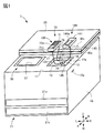
図1は本実施形態に係る画像形成装置の概略構成を示す斜視図である。
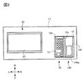
図2は本実施形態に係る画像形成装置の操作面を示す平面図である。
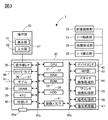
図3は本実施形態に係る画像形成装置の制御ブロック図である。
図4は本実施形態に係る画像形成装置のテンキーユニットを示す斜視図である。
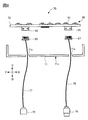
図5は本実施形態に係る画像形成装置のテンキーユニットを示す分解斜視図である。
図6は本実施形態に係る画像形成装置のテンキーユニットの平面図である。
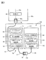
図7は本実施形態に係る画像形成装置のテンキーユニット及びICカードリーダの制御ブロック図である。
図8は本実施形態に係る画像形成装置のテンキーユニットの基板及び筐体を示す側面図である。
図9は他の画像形成装置の周辺装置の概略構成を示す図であり、(a)は斜視図、(b)は平面図である。
以下、本発明の実施形態を、図1~図8を参照しながら詳細に説明する。尚、本実施形態では、各図に示すように、画像形成装置1に向かって手前側を前側F、奥側(背側)を後側B、左側をL、右側をR、上側をU、下側をDとして表している。また、画像形成装置1は、ユーザは前側Fから後側Bを向いて位置して各種の操作を行う構成になっている。図1に示すように、本実施形態においては、後述する操作部50が設けられる側が、画像形成装置1の前側Fである。
本実施形態では、画像形成装置1の一例として、タンデム型のフルカラープリンタについて説明している。但し、本発明はタンデム型の画像形成装置1に搭載されることには限られず、他の方式の画像形成装置に搭載されるものであってもよく、また、フルカラーであることにも限られず、モノクロやモノカラーであってもよい。あるいは、プリンタ、各種印刷機、複写機、FAX、複合機等、種々の用途で実施することができる。
<画像形成装置>
<画像形成装置>
図1に示すように、本実施形態の画像形成装置1は、画像形成装置本体(以下、装置本体という)10を備えている。装置本体10は、画像読取部20と、シート給送部21と、画像形成部22(図3参照)と、シート排出部23(図3参照)と、制御部30(図3参照)と、操作部50と、を備えている。図1に示すように、操作部50は、鉛直方向においてシート排出部23よりも上方に設けられる。尚、記録材であるシートは、トナー像が形成されるものであり、具体例として、普通紙、普通紙の代用品である樹脂製のシート、厚紙、オーバーヘッドプロジェクタ用シート等がある。
画像読取部20は、例えば、フラットベットスキャナ装置であり、装置本体10の上部に設けられている。画像読取部20は、原稿載置台としての不図示のプラテンガラスと、プラテンガラスに載置された原稿に光を照射する不図示の光源と、反射光をデジタル信号に変換する不図示のイメージセンサ等を備えている。シート給送部21は、装置本体10の下部に配置されており、記録紙等のシートを積載して収容するシートカセット21a,21bを備え、シートを画像形成部22(図3参照)に給送する。
画像形成部22は、装置本体10の内部に設けられ、いずれも不図示の現像装置及び像担持体としての感光ドラムを有する画像形成ユニット、トナーボトル、中間転写ユニット、二次転写部、定着装置等を有している。画像形成部22は、シート給送部21から給送されたシートに対して、制御部30からの画像情報に基づいて画像を形成可能である。シート排出部23は、シートを装置本体10に形成された不図示の排出口の下流側に配置された不図示の排出トレイを備えている。図1にはシート排出部23を不図示としているが、鉛直方向において画像読取部20よりも下方に排出トレイを備えるような所謂胴内排出構成に本実施形態を適用してもよい。
装置本体10の前側Fの上側Uには、操作面11が設けられている。図2に示すように、操作面11には、操作部50と、テンキーユニット70と、ICカードリーダ140との操作面が上側Uを向いて設けられている。テンキーユニット70及びICカードリーダ140は、画像形成装置1の周辺装置として装置本体10に取り付けられており、これらの構成については後述する。装置本体10の右側Rの側面の上部には、操作者によってUniversal Serial Bus(以下、USBと称す)メモリ等のUSB端子を持つ外部機器を装着可能なUSBポート10aが設けられている。尚、このUSBポート10aは設けられていなくてもよい。
<制御部>
<制御部>
図3に示すように、制御部30はコンピュータにより構成され、例えばCPU31と、データを一時的に記憶するRAM32と、各部を制御するプログラムを記憶するROM33及びHDD34とを備えている。本実施形態では、制御部30は、システムバス30aと画像バス30bとを有し、CPU31、RAM32、ROM33、HDD34はいずれもシステムバス30aに接続されている。CPU31は、画像形成装置1の全体を統括的に制御するプロセッサであり、システムコントローラの主体である。CPU31は、例えば、画像形成される画像データの画像処理や、ネットワーク制御を行う他、画像形成部22に画像形成の指示を出力することによって画像形成処理を制御する。
RAM32は、CPU31が動作するためのシステムワークメモリであり、画像データを一時記憶するための画像メモリでもあり、CPU31の主メモリやワークエリア等として機能する。RAM32には、画像形成装置1内の設定情報や各処理を行った時のジョブログや操作ログなどが格納される。ROM33には、シートに画像を形成するための画像形成制御シーケンス等が記憶される。本実施形態では、ROM33は、例えばブートROMであり、システムのブートプログラムが格納されている。HDD34は、ハードディスクドライブであり、システムソフトウェア、アプリケーション、画像データなどを格納する。
制御部30は、いずれもシステムバス30aに接続される操作部入出力回路(I/F)35と、ネットワーク入出力回路(I/F)36と、モデム37と、SRAM38と、RTC39と、外部入出力回路(I/F)40と、を有している。操作部入出力回路35は、後述する操作部50への画像データの送信や、操作部50からの各種通信を行うと共に、操作部50からユーザが入力した情報をCPU31に入力する。
ネットワーク入出力回路36は、ネットワーク90に接続し、情報の入出力を行う。また、モデム37は公衆回線91に接続し、ファクシミリを送受信可能なファクシミリ通信部として機能し、情報の入出力を行う。これにより、制御部30は、CPU31の指示の下、ネットワーク入出力回路36によりネットワーク90を介して、あるいはモデム37により公衆回線91を介して、接続された他のPCやサーバと通信可能である。即ち、画像形成装置1は、ネットワーク90や公衆回線91と接続することで、画像情報やデバイス情報の入出力を行う。
SRAM38は、高速動作可能な不揮発性の記憶媒体である。RTC39は、リアルタイムクロックであり、制御部30に電源が入っていない状態でも現在の時刻をカウントし続ける処理を行う。外部入出力回路40は、USB等の汎用入出力回路であり、汎用のPCや、メモリデバイス、後述するテンキーユニット70を、USBコネクタ40aを介して接続する。本実施形態では、USBコネクタ40aは、制御基板30c(図4参照)にレセプタクルとして実装されている。図1に示すように、制御基板30cは、USBコネクタ40aが画像形成装置1の操作面11の近傍に配置されるように装置本体10に収容されている。USBコネクタ40aには、テンキーユニット70の本体側ケーブル76のUSBプラグ78が結合して接続されている。尚、制御基板30cは、この配置に限られず、画像形成装置1の後側B(背面側)に設けられる構成であってもよい。この構成の場合は、USBコネクタ40aのみを前側Fに設け、USBコネクタ40aと制御基板30cとをケーブルで接続する構成であればよい。
図3に示すように、制御部30は、画像バス入出力回路(I/F)41を有している。画像バス入出力回路41は、システムバス30aと画像データを高速で転送する画像バス30bとを接続し、データ構造を変換するバスブリッジである。画像バス30bは、例えば、PCIバス又はIEEE1394で構成されている。
制御部30は、いずれも画像バス30bに接続されるデバイス入出力回路(I/F)42と、RIP部43と、スキャナ画像処理部44と、プリンタ画像処理部45と、暗号処理部46と、復号処理部47とを有している。デバイス入出力回路42は、画像読取部20や画像形成部22を制御部30に接続し、画像データの同期系及び非同期系の変換を行う。RIP部43は、ラスターイメージプロセッサであり、PDLデータをビットマップイメージに展開する。スキャナ画像処理部44は、入力画像データに対し補正、加工、編集を行う。プリンタ画像処理部45は、プリント出力画像データに対して、プリンタの補正、解像度変換等を行う。暗号処理部46は、画像データを含む入力データの暗号化処理を行う。復号処理部47は、暗号化データの復号化処理を行う。
操作部50は、操作者が操作を行うためのもので、各種の情報を表示する表示部51と、操作者が操作入力を行う入力部52を有している。本実施形態では、操作部50は、例えば、液晶モジュールである表示部51及びタッチパネルモジュールである入力部52が一体化されたタッチ入力式のパネル面57を有している。このパネル面57では、表示部51に所定の処理を開始する情報を入力可能なスタートキーや0~9の数値を入力可能なソフトウェアキーを表示可能であり、入力部52により情報を入力可能である。尚、操作部50は操作パネルの一例である。
図1に示すように、操作部50は、装置本体10の操作面11に設けられている。また、図1に示すように、操作部50は、画像形成装置1の前後方向における中央部よりも前側Fに設けられている。操作部50は、例えば四角形の平板状に形成されており、入力部52が表示部51(図3参照)の上に積層されて構成されるパネル面57を上側Uに向けて、装置本体10に固定して設けられている。パネル面57に表示されたソフトウェアキーは、各表示部分がタッチ操作されることでキーの入力を検知する入力キーになっている。尚、操作部50の形状は四角形の平板状には限られず、他の形状であってもよい。また、表示部51及び入力部52の向きは上側Uには限られず、他の方向であってもよく、例えば、装置本体10に対して上下方向にチルト可能であってパネル面57の向きが変更可能となるように設けられていてもよい。
<テンキーユニット>
<テンキーユニット>
次に、画像形成装置1に接続される周辺装置の1つである入力装置としてのテンキーユニット70のハードウェア構成及び動作について説明する。図2に示すように、操作部50の右横にテンキーユニット70が設置されている。このテンキーユニット70は、情報を入力可能な操作部50を有する画像形成装置1に装着され、操作部50とは別に画像形成装置1に情報を入力可能である。操作部50とテンキーユニット70との情報入力の使い分けの一例としては、操作部50からは画像形成に関する濃度やサイズ等の設定を入力し、テンキーユニット70からは画像形成の部数やファクシミリの宛先番号等の数値を入力する。尚、本明細書でテンキーとは、0~9までの10個の数値キーを示す場合、数値キーに「*」,「#」を加えた12個のキーを示す場合、数値キーに四則演算子や「NumLock」等を含む20個前後のキーを示す場合のいずれも含む概念としている。
テンキーユニット70は、筐体71と、筐体71の上面に設けられた上面カバー72と、上面カバー72に設けられた操作キー(数値キー部)100とを有している。操作キー100は、筐体71が画像形成装置1の装置本体10に装着された状態において筐体71の上面カバー72の上面(筐体の上面)72aに配置されている。操作キー100の配列については後述する。図1に示すように、装着部12は操作部50に隣接して配置されており、筐体71は、画像形成装置1の操作部50の右側に隣接して、装着部12に例えばねじ止めや接着などにより装着されている。また、操作部50及び装着部12は、装置本体10の正面側に配置されている。これにより、ユーザは操作部50を見ながら、右手を利用して容易にテンキーユニット70を使用することができる。
図5に示すように、テンキーユニット70は、基板73と、基板73に設けられたハードウェアキーユニット80及びLED74,75と、本体側ケーブル76と、外部側ケーブル77と、を有している。基板73は、テンキーユニット70を制御する電気回路を有している。本体側ケーブル76は、筐体71から外部に突出して設けられたUSBケーブルであり、その先端にはUSB端子であるUSBプラグ(プラグ)78が設けられている。即ち、本体側ケーブル76は、後述する第1の開口71aに挿通され、筐体71から外部に露出するように設けられている。これにより、画像形成装置1とテンキーユニット70とは、本体側ケーブル76を介して電気的に接続される。
外部側ケーブル77は、本体側ケーブル76とは別に設けられ、筐体71から外部に突出して設けられたUSBケーブルであり、その先端にはUSB端子であるUSBレセプタクル(レセプタクル)79が設けられている。即ち、本体側ケーブル76及び外部側ケーブル77の一方である本体側ケーブル76は先端にUSBプラグ78を有し、本体側ケーブル76及び外部側ケーブル77の他方である外部側ケーブル77は先端にUSBレセプタクル79を有している。但し、これとは逆に、本体側ケーブル76及び外部側ケーブル77の一方である外部側ケーブル77が先端にUSBプラグを有し、本体側ケーブル76及び外部側ケーブル77の他方である本体側ケーブル76が先端にUSBレセプタクルを有してもよい。USBプラグ78及びUSBレセプタクル79は、USB規格に基づく形状及び構成を有している。尚、本体側ケーブル76及び外部側ケーブル77の筐体71からの突出位置については、後述する。
ハードウェアキーユニット80は、複数のハードウェアキーを有している。本実施形態では、ユーザに操作キー100の操作感(例えばクリック感)を与えるべく、ハードウェアキーの一例としてタクタイルスイッチ81を適用している。タクタイルスイッチ81は、それぞれの操作キー100の筐体71内側に対向する位置に1個ずつ配置される。タクタイルスイッチ81は、例えば、保護カバーと、操作キー100により押されるプランジャと、クリック感を生み出すと共に可動接点として機能する反転ばねと、2つの接点を有するベース部と、により構成されている。これにより、操作キー100が押下されることによって、対応するタクタイルスイッチ81が押下され、数値などの値を入力することが可能となっている。つまり、操作キー100とタクタイルスイッチ81とは、ユーザによって少なくとも0~9の数値に関する情報を入力可能なハードウェアキーの一例である。尚、タクタイルスイッチ81としては、既存の又は新規の適宜な構成を適用することができるので、詳細な説明は省略する。
第1のLED74は、筐体71内において後述するスタートキー131(図6参照)の裏側に設けられ、制御部30(図2参照)からの信号に基づいて発光される。制御部30は、画像形成部22(図3参照)が画像形成可能な状態になった場合に、第1のLED74を発光させ、画像形成部22が画像形成可能な状態でない場合に、第1のLED74を消灯させる。
第2のLED75は、筐体71内において後述する設定キー121(図6参照)の裏側に設けられ、制御部30(図2参照)からの信号に基づいて発光される。制御部30は、画像形成装置1のモードが所定のモード、例えば音声入力モードに設定された場合に、第2のLED75を発光させ、画像形成装置1のモードが所定のモードでない場合に、第2のLED75を消灯させる。
図6に示すように、操作キー100は、テンキー部110と、動作キー部130と、設定キー部120と、を有している。図6は、テンキーユニット70を正面視したものであり、各ハードウェアキーの押し下げ方向と平行な方向から視た図である。尚、ここでの正面視とは、テンキーユニット70のハードウェアキーに設けられている数値が上下方向において正しく見える位置である。テンキー部110は、少なくとも数値に関する情報を入力可能な複数のハードウェアキーを有する。動作キー部130は、例えば、所定の処理を開始する情報を入力可能なハードウェアキーからなるスタートキー131を有する。ここでの所定の処理とは、例えば、画像形成装置1のコピー処理、ファクシミリの送信処理や画像読取部20の画像読取処理などであり、スタートキー131の押し下げによりこれらの処理の実行開始を指示することができる。スタートキー131は、筐体71が画像形成装置1に装着された状態において、テンキー部110より手前側に配置されている。設定キー部120は、例えば、画像形成装置1の所定のモード(例えば、ユーザの音声によって入力操作を行う音声入力モード)を設定する情報を入力可能なハードウェアキーからなる設定キー121を有する。つまり、操作キー100は、表示部51に表示されるソフトウェアキーに対応するハードウェアキーを有している。
ここで、本実施形態のテンキーユニット70は、画像形成装置1のオプション装置の一つとして設計される画像形成装置1の専用のテンキーユニット70である。この専用のテンキーユニット70の用途は、例えば、ファクシミリ送信する際の宛先番号(FAX番号)入力が主になる。専用のテンキーユニット70は、ファクシミリ送信の宛先番号入力を主目的として設計されるため、テンキー部110の配列は電話機と同様である。つまり、専用テンキーユニット70のテンキー部110の配列は、ITU−T(国際電気通信連合電気通信標準化部門)RecommendationE.161に示される標準配列と同様である。従って、テンキー部110は、数値入力が可能なハードウェアキーからなる数値キー部と、「*」や「#」の入力が可能なハードウェアキーを有している。ここで、「*」や「#」のハードウェアキーは、画像形成装置1がFAXモードの場合に有効なキーとしている。例えば、画像形成装置1がFAXモードの場合に、ユーザが「*」や「#」のハードウェアキーを操作することにより、「*」や「#」の情報が制御部30に送信される。即ち、図6に示すように、テンキー部110において、1から9の数値キーは、最も後側Bが1から3、その前側Fが4から6、その前側Fが7から9となるように隣接配置されている。また、8の数値キーの前側Fに0の数値キーが配置され、その左右に*のキーと#のキーとが配置されている。
換言すると、0から9の10個のハードウェアキーに関して、1,2,3のハードウェアキーの行が最も奥に配置され、1,2,3の行よりも手前側に4,5,6のハードウェアキーの行が配置される。さらに、4,5,6のハードウェアキーの行よりも手前側に、7,8,9のハードウェアキーの行が配置される。そして、0のハードウェアキーは、7,8,9のハードウェアキーの行よりも手前側に配置される。また、これらの0から9のハードウェアキーを列で見ると、左から1,4,7のハードウェアキーの列、2,5,8,0のハードウェアキーの列、3,6,9のハードウェアキーの列の順に配列されている。つまり、1~9の数値キーは、専用テンキーユニット70を正面視した場合に3×3のマトリクス状に整列配置されており、列方向において上段から1乃至3の数値キー、4乃至6の数値キー、7乃至9の数値キーが順に配置され、0の数値キーが7乃至9の数値キーの行よりもさらに下段に配置されている。尚、0のハードウェアキーは、1,4,7のハードウェアキーの列、あるいは3,6,9のハードウェアキーの列に配置し、*のキーと#のキーの配置を適宜変更してもよい。更に、このテンキーユニット70では、電卓入力は主目的とされていないため、+や−などの四則演算子キーは設けられていない。このように、このテンキーユニット70は、PCに接続する目的で設計されていないため、不特定のPC等に接続可能な汎用のテンキーユニットとはキー配列が異なっている。
ここで、汎用のテンキーユニットのキー配列とは、主に電卓と同じキー配列となっている。つまり、汎用テンキーユニットにおけるハードウェアキーの配列は、ISO(国際標準化機構)に規定されるものと同様である。即ち、汎用テンキーユニットにおいて、0から9の10個のハードウェアキーに関して、7,8,9のハードウェアキーの行が最も奥に配置され、7,8,9の行よりも手前側に4,5,6のハードウェアキーの行が配置される。さらに、4,5,6のハードウェアキーの行よりも手前側に、1,2,3のハードウェアキーの行が配置される。つまり、汎用テンキーユニットにおいて、1~9の数値キーは、3×3のマトリクス状に整列配置されており、列方向において上段から7乃至9の数値キー、4乃至6の数値キー、1乃至3の数値キーが順に配置され、0の数値キーが1乃至3の数値キーの行よりもさらに下段に配置されている。そして、0や00のハードウェアキーは、1,2,3のハードウェアキーの行よりも手前側に配置される。また、これらの1から9のハードウェアキーを列で見ると、左から1,4,7のハードウェアキーの列、2,5,8のハードウェアキーの列、3,6,9のハードウェアキーの列の順に配列されている。0や00のハードウェアキーは、1,4,7のハードウェアキーの列、2,5,8のハードウェアキーの列に跨って配置されたり、1,4,7と同じ列に配置されている。更に、数値キーの右側及び後側に、四則演算子キーや機能キー部等が配置されている。このように、テンキーユニット70と汎用のテンキーユニットとは、数値キーの配列や、設けられる機能キー等が異なっている。
また、本実施の形態においては、テンキー部110のレイアウトを、後側Bの数値が小さく前側Fの数値が大きい電話型のキー配列としている。但し、これには限られず、テンキー部110のレイアウトを、後側Bの数値が大きく前側Fの数値が小さい、上述した汎用のテンキーユニットと同様のキー配列としてもよい。
<周辺装置の制御系>
<周辺装置の制御系>
次に、画像形成装置1に接続される周辺装置の制御系について、図7を用いて説明する。本実施形態では、画像形成装置1に接続される周辺装置として、テンキーユニット70とICカードリーダ140とが接続されている。尚、ここでの周辺装置とは、例えば、画像形成装置1に接続されて使用可能な装置であり、例えば、テンキーユニット70とICカードリーダ140とをそれぞれ単体で画像形成装置1に接続しても使用可能なものとしている。
図7に示すように、テンキーユニット70の基板73(図5参照)には、USBハブ制御部82と、USBデバイス制御部と、ハードウェアキーユニット80とが設けられている。USBハブ制御部82は、USB接続のハブ制御機能を提供するものであり、USB接続を拡張することができる。USBデバイス制御部83は、USB接続におけるUSB通信のデバイス制御を行うためのものである。キー制御部84は、ハードウェアキーユニット80によるキー入力を検出するためのものである。
USBハブ制御部82には、USBホスト側との接続用に、本体側ケーブル76とその先端のUSBプラグ78とが接続されている。また、USBハブ制御部82には、USBハブのポートに対して、USBデバイス制御部83が接続されている。更に、USBハブ制御部82のUSBハブの他のポートに対して、他のUSBデバイスとの接続用に、外部側ケーブル77とその先端のUSBレセプタクル79とが接続されている。
一方、ICカードリーダ140は、筐体141と、USBデバイス制御部142と、ICカードリーダ制御部143と、ICカード読取部144と、接続ケーブル145と、を有している。また、接続ケーブル145は、筐体141から外部に突出して設けられたUSBケーブルであり、その先端にはUSB端子であるUSBプラグ146が設けられている。USBプラグ146は、USB規格に基づく形状及び構成を有している。USBデバイス制御部142は、USB接続におけるUSB通信のデバイス制御を行うためのものである。USBデバイス制御部142には、USBホスト側との接続用に、接続ケーブル145とその先端のUSBプラグ146とが接続されている。
ICカード読取部144は、ICカードの情報を電磁気的に読み取り可能であり、ユーザにより近接(タッチ)されるICカードのICチップの情報を読み取るためのものであり、筐体141の上面側に設けられた読取面144aを有している(図1参照)。ICカードリーダ制御部143は、ICカード読取部144によるICカード情報の読み取りを制御するためのものである。図1に示すように、接続ケーブル145は、筐体141のICカード読取部144の読取面144aの反対側の面から突出している。
図7に示すように、テンキーユニット70のUSBプラグ78は、画像形成装置1のUSBコネクタ40aに接続されることにより、本体側ケーブル76を介して画像形成装置1にUSB接続される。また、ICカードリーダ140のUSBプラグ146は、テンキーユニット70のUSBレセプタクル79に接続されることにより、接続ケーブル145及び外部側ケーブル77を介して、テンキーユニット70にUSB接続される。これらのUSB接続を行うことにより、画像形成装置1と、テンキーユニット70と、ICカードリーダ140との間のUSB通信が可能になる。キー制御部84により処理されたキー入力情報は、USB接続通信を介して、画像形成装置1の制御部30のCPU31により読み出されるようになる。また、ICカードリーダ制御部143により処理されたICカード読取情報は、USB接続通信を介して、画像形成装置1の制御部30のCPU31により読み出されるようになる。
上述したように画像形成装置1の周辺装置は、ケーブルとプラグ及びレセプタクルとを介して画像形成装置1と接続して機能する構成になっているのが一般的である。ここで、図9(a)に示すように、例えば、キーボードユニット(入力装置)やICカードリーダ等の周辺装置150が、画像形成装置1に接続するためのケーブル151と、他の周辺装置が接続可能なようにレセプタクル152とを有していたとする。ケーブル151は、画像形成装置1と接続を行うためのケーブルであり、周辺装置150の後側Bの側面から外側に突出して引き出されるように設けられている。レセプタクル152は、この周辺装置150に他の周辺装置を接続するために設けられている。一般に、周辺装置の上面はユーザが各種の操作を行うためのキーや表示装置等が配置される。このため、周辺装置を接続するためのケーブルやレセプタクルは周辺装置の側面に配置されることが多い。ここでは、例えば、この周辺装置150の右側Rに他の周辺装置を配置することを考慮して、周辺装置150の右側Rの側面に配置されている。
図9(b)に示すように、この周辺装置150のレセプタクル152には、他の周辺装置のケーブル161のプラグ162が結合されて接続される。しかしながら、この場合、周辺装置150のケーブル151と、他の周辺装置のプラグ162とが、いずれも周辺装置150の側面から側方に突出した状態になってしまう。このため、これらの周辺装置150を画像形成装置1に搭載して配置する場合、ケーブルやプラグ等の突出部が周辺の構造物や他の周辺装置と干渉してしまう虞がある。また、このような突出部による干渉を回避するために、周辺装置の装着部12を大きく確保する必要があり、装置本体10の内部の設計の自由度が低下したり、外観のデザイン性が損なわれる可能性がある。これに対し、本実施形態では、周辺機器のケーブルが側方から突出しないようにして、ケーブルでの接続に伴う画像形成装置1の装置本体10の大型化を抑制するようにしている。
<本体側ケーブル及び外部側ケーブル>
<本体側ケーブル及び外部側ケーブル>
次に、このような課題を解決するためのテンキーユニット70の本体側ケーブル76及び外部側ケーブル77の筐体71への取付構造について、詳細に説明する。図5に示すように、本体側ケーブル76及び外部側ケーブル77は、筐体71の操作キー100が設けられる面に対して反対側の面から突出している。図5及び図8に示すように、本体側ケーブル76及び外部側ケーブル77の各基端は、いずれも基板73の裏面側、即ち基板73のハードウェアキーユニット80の実装面とは反対側の面に接続されている。つまり、基板73の板厚方向において、本体側ケーブル76及び外部側ケーブル77の各基端は、タクタイルスイッチ81の実装面とは反対側に実装されている。筐体71の底部には、筐体71の内外を貫通する第1の開口(開口部)71a及び第2の開口(別の開口部)71bが形成されている。即ち、開口71a,71bは、筐体71が画像形成装置1の装置本体10に装着された状態において筐体71の底面71cに設けられている。本体側ケーブル76が第1の開口71aを通過することにより、筐体71の内部側から外部側に向けて突出して設けられ、本体側ケーブル76及びUSBプラグ78がテンキーユニット70の外部に引き出される。また、外部側ケーブル77が第2の開口71bを通過することにより、筐体71の内部側から外部側に向けて突出して設けられ、外部側ケーブル77及びUSBレセプタクル79がテンキーユニット70の外部に引き出される。つまり、第1の開口71a及び第2の開口71bは、基板73の板厚方向において、操作キー100が設けられる面に対して反対側である底面71cから本体側ケーブル76及び外部側ケーブル77が筐体71の外部へ露出するように筐体71cに設けられている。
図8に示すように、基板73の裏面側、即ち基板73のハードウェアキーユニット80の実装面とは反対側の面には、第1汎用コネクタレセプタクル85及び第2汎用コネクタレセプタクル86が実装されている。一方、本体側ケーブル76において、USBプラグ78の反対側の端部には、第1汎用コネクタプラグ87が取り付けられている。第1汎用コネクタプラグ87は、基板73の第1汎用コネクタレセプタクル85に結合することにより、本体側ケーブル76と基板73とが接続される。また、外部側ケーブル77において、USBレセプタクル29の反対側の端部には、第2汎用コネクタプラグ88が取り付けられている。第2汎用コネクタプラグ88は、基板73の第2汎用コネクタレセプタクル86に結合することにより、外部側ケーブル77と基板73とが接続される。
一方、図1に示すように、操作面11において操作部50の右側Rには、操作部50に隣接した装置本体10の前側Fの右側Rで上側Uを向いた装着部12が設けられている。装着部12は、操作面11に対して凹部形状の空間(収容部)を形成しており、ここにテンキーユニット70及びICカードリーダ140などの周辺装置を格納する。即ち、装着部12は、テンキーユニット70及びICカードリーダ140を収容して装着する凹部形状を有している。尚、装着部12にテンキーユニット70やICカードリーダ140などの周辺機器を装着しない場合は、外観を損なわないように蓋13を設けて外部から覆い隠すようにする。
装着部12にテンキーユニット70及びICカードリーダ140を装着する際は、テンキーユニット70の本体側ケーブル76のUSBプラグ78を、制御基板30cのUSBコネクタ40aに接続する。このとき、本体側ケーブル76は、例えば、装着部12の後側Bの側壁12aの下部をくぐらせて、テンキーユニット70から制御基板30cまで配線する。テンキーユニット70の外部側ケーブル77のレセプタクル79には、ICカードリーダ140の接続ケーブル145のUSBプラグ146が接続される。接続された本体側ケーブル76、外部側ケーブル77、接続ケーブル145は、装着部12の底部、即ち、装着部12の底面12bとテンキーユニット70の底面71c(図4参照)との間の空間に収容される。その後、テンキーユニット70の筐体71及びICカードリーダ140の筐体141を装着部12において本体側ケーブル76、外部側ケーブル77、接続ケーブル145の上側Uに装着する。テンキーユニット70及びICカードリーダ140は、装着部12に対して例えばねじ止めや接着等により固定される。そして、図2に示すように、テンキーユニット70及びICカードリーダ140は、装着部12の内部において互いに隣接して設置されるようにできる。
このように、本実施形態では、画像形成装置1は、装置本体10に接続されて使用可能な周辺装置として、ICカードリーダ140が取り付けられている。外部側ケーブル77は、テンキーユニット70の底面71cに形成された第1の開口71aとは別の第2の開口71bを通過して筐体71の内部側から外部側に向けて突出して設けられると共に、ICカードリーダ140に接続されている。ICカードリーダ140は、テンキーユニット70と共に装着部12に収容されて装着される。
尚、本体側ケーブル76の線長は、USBコネクタ40aとテンキーユニット70の間の配線経路に基づき、装着部12の底面12bとテンキーユニット70の底面71cとの間の空間に収容できるように決定するようにする。また、外部側ケーブル77の線長は、ICカードリーダ140の接続ケーブル145の線長を考慮して、装着部12の底面12bとテンキーユニット70の底面71cとの間の空間に外部側ケーブル77及び接続ケーブル145を収納できる長さとする。
上述したように、本実施形態の画像形成装置1によれば、テンキーユニット70の本体側ケーブル76及び外部側ケーブル77は、テンキーユニット70の筐体71の下面から露出している。これらの本体側ケーブル76及び外部側ケーブル77は、装着部12においてテンキーユニット70及びICカードリーダ140の下側Dに収納することができる。このため、テンキーユニット70の本体側ケーブル76や外部側ケーブル77、並びにテンキーユニット70に接続されるICカードリーダ140のUSBプラグ146が、画像形成装置1の側方に突出したり、他の部材等に干渉することを抑制できる。また、画像形成装置1の側方等でケーブルを束ねたり、あるいは装置本体の外面に固定することによって外観品位が低下することを抑制できる。これにより、テンキーユニット70及びICカードリーダ140を好適に配置でき、必要以上に設置面積を増大させることなく、デザイン的にも良好な配置が可能になる。従って、本実施形態の画像形成装置1によれば、画像形成装置1に本体側ケーブル76により接続可能な外付け用のテンキーユニット70でありながら、本体側ケーブル76及び外部側ケーブル77での接続に伴う装置本体10の大型化を抑制できる。
また、本実施形態の画像形成装置1によれば、本体側ケーブル76、外部側ケーブル77、接続ケーブル145をユーザから見えないように収容できるので、プラグ及びレセプタクルの接続をユーザにより不用意に抜かれてしまうことを防止できる。更に、本実施形態の画像形成装置1によれば、装着部12にテンキーユニット70の他にICカードリーダ140を装着しており、ICカードリーダ140の接続ケーブル145も筐体141の下方から突出して設けられている。このため、ICカードリーダ140の接続ケーブル145が側方に突出したり、他の部材等に干渉することを抑制できる。
また、本実施形態の画像形成装置1によれば、ICカードリーダ140が装着されない場合は、外部側ケーブル77を装着部12の収容空間、即ちテンキーユニット70の下方の空間に収容できる。このため、外部側ケーブル77が外部に露出することによる周辺機器への干渉や、ユーザによる誤った引き抜きを抑制できる。また、この場合、装着部12のうちテンキーユニット70で覆われない部分にカバー部材等を設ける構成であってもよい。
尚、上述した実施形態では、テンキーユニット70は外部側ケーブル77を有する場合について説明したが、外部側ケーブル77は無くてもよい。この場合も、画像形成装置1に本体側ケーブル76により接続可能な外付け用のテンキーユニット70でありながら、本体側ケーブル76での接続に伴う装置本体10の大型化を抑制できる。
また、本実施形態では、図8に示すように、第1汎用コネクタレセプタクル85及び第2汎用コネクタレセプタクル86を基板73の裏面側に配置した場合について説明したが、これには限られない。例えば、第1汎用コネクタレセプタクル85及び第2汎用コネクタレセプタクル85を基板73の表面側(上面カバー72に面する側)に配置しても構わない。この場合は、第1汎用コネクタプラグ87及び第2汎用コネクタプラグ88は、基板73の表面で第1汎用コネクタレセプタクル85及び第2汎用コネクタレセプタクル86とそれぞれ結合して接続することになる。従って、本体側ケーブル76及び外部側ケーブル77をテンキーユニット70の外部に引き出す際には、基板73の表面から裏面に回り込ませて筐体71の底面の開口71a,71bから引き出すようにする。この場合も、画像形成装置1に本体側ケーブル76により接続可能な外付け用のテンキーユニット70でありながら、本体側ケーブル76及び外部側ケーブル77での接続に伴う装置本体10の大型化を抑制できる。
また、本実施形態では、画像形成装置1、テンキーユニット70、ICカードリーダ140の接続は、USB規格に基づく通信によるものとして、本体側ケーブル76、外部側ケーブル77、接続ケーブル145をUSBケーブルとした場合について説明した。但し、必ずしもUSB規格に基づいたケーブルであることには限られず、USB信号の伝送品質に問題がなければ、これらのケーブルを汎用のケーブルで構成してもよい。
本発明によれば、画像形成装置にケーブルにより接続可能な外付け用の入力装置でありながら、ケーブルが外部に露出することによる周辺機器への干渉や、ユーザによる誤った引き抜きを抑制できる入力装置及び画像形成装置が提供される。
本発明は上記実施の形態に制限されるものではなく、本発明の精神及び範囲から離脱することなく、様々な変更及び変形が可能である。従って、本発明の範囲を公にするために以下の請求項を添付する。
本願は、2019年2月5日提出の日本国特許出願特願2019−018771を基礎として優先権を主張するものであり、その記載内容の全てをここに援用する。
Claims (12)
- 記録媒体に対して画像を形成する画像形成部と、ソフトウェアキーとして0~9の数値情報をそれぞれ入力するためのソフトウェア数値キーを表示可能な表示画面を有する操作パネルとを備えた画像形成装置の装着部に対して装着可能な入力装置であって、
前記装着部に装着される筐体と、
少なくとも0~9の数値に関する情報を入力可能なハードウェアキーとしてのハードウェア数値キー部と、
前記筐体内に設けられ、前記数値キー部が実装される基板と、
前記基板に実装されるコネクタに接続されるケーブルであって、前記画像形成装置と前記入力装置とを電気的に接続するケーブルと、
前記ケーブルが挿通される開口部であって、前記基板の板厚方向において、前記ハードウェア数値キー部が設けられる面に対して反対側の面から前記ケーブルが前記筐体の外部へ露出するように前記筐体に設けられる開口部と、を備える、
入力装置。 - 前記コネクタは、前記基板の板厚方向において前記基板の前記ハードウェア数値キー部が実装される面と反対側の面に実装されている、
請求項1に記載の入力装置。 - 前記基板に実装される他のコネクタに接続され、ICカードの情報を電磁気的に読み取り可能な情報読取装置に電気的に接続される他のケーブルをさらに備え、
前記筐体は、前記基板の板厚方向において、前記ハードウェア数値キー部が設けられる面に対して反対側の面から前記他のケーブルが前記筐体の外部へ露出するように設けられる他の開口部を備える、
請求項1または2に記載の入力装置。 - 前記他のコネクタは、前記基板の板厚方向において前記基板の前記ハードウェア数値キー部が実装される面と反対側の面に実装されている、
請求項3に記載の入力装置。 - 前記ケーブル及び前記他のケーブルの一方は、先端にプラグを有し、
前記ケーブル及び前記他のケーブルの他方は、先端にレセプタクルを有する、請求項3または4に記載の入力装置。 - 前記ハードウェア数値キー部は、
前記基板に実装される複数のタクタイルスイッチと、
前記複数のタクタイルスイッチに対応するように設けられる複数の操作キー部であって、ユーザによって押下されることで前記複数のタクタイルスイッチをそれぞれ押下可能となるように前記筐体に設けられる複数の操作キー部と、を有する、
請求項1乃至5のいずれか1項に記載の入力装置。 - 原稿の画像を読み取る画像読取装置と、
前記画像読取装置の読取結果に基づいて記録媒体に画像を形成する前記画像形成部を内部に有し、前記画像形成装置の前後方向において前記画像読取装置よりも正面側に設けられた前記装着部を有する装置本体と、
請求項1乃至6のいずれか1項に記載の入力装置と、を備える、
画像形成装置。 - 前記装着部は、前記入力装置を収容して装着する凹部形状の収容部を有し、
前記ケーブルは、前記筐体が前記装置本体に装着された状態において、前記収容部に収容されている、
請求項7に記載の画像形成装置。 - 前記装着部に収容された前記ケーブルは、前記装着部の底面と前記入力装置の前記筐体の前記ハードウェア数値キー部が設けられる面と反対側の面との間の空間に収容される、
請求項8に記載の画像形成装置。 - 前記装着部は、前記装置本体に対して前記操作パネルに隣接して配置されている、
請求項7乃至9のいずれか1項に記載の画像形成装置。 - 前記操作パネル及び前記装着部は、前記装置本体の正面側に配置されている、
請求項7乃至10のいずれか1項に記載の画像形成装置。 - ICカードの情報を電磁気的に読み取り可能な情報読取装置を備え、
前記情報読取装置は、前記入力装置と共に前記装着部に収容されて装着される、
請求項7乃至11のいずれか1項に記載の画像形成装置。
Priority Applications (1)
| Application Number | Priority Date | Filing Date | Title |
|---|---|---|---|
| US17/391,148 US11509783B2 (en) | 2019-02-05 | 2021-08-02 | Input device and image forming apparatus |
Applications Claiming Priority (2)
| Application Number | Priority Date | Filing Date | Title |
|---|---|---|---|
| JP2019-018771 | 2019-02-05 | ||
| JP2019018771 | 2019-02-05 |
Related Child Applications (1)
| Application Number | Title | Priority Date | Filing Date |
|---|---|---|---|
| US17/391,148 Continuation US11509783B2 (en) | 2019-02-05 | 2021-08-02 | Input device and image forming apparatus |
Publications (1)
| Publication Number | Publication Date |
|---|---|
| WO2020162636A1 true WO2020162636A1 (ja) | 2020-08-13 |
Family
ID=71948119
Family Applications (1)
| Application Number | Title | Priority Date | Filing Date |
|---|---|---|---|
| PCT/JP2020/005013 Ceased WO2020162636A1 (ja) | 2019-02-05 | 2020-02-04 | 入力装置及び画像形成装置 |
Country Status (3)
| Country | Link |
|---|---|
| US (1) | US11509783B2 (ja) |
| JP (1) | JP7486965B2 (ja) |
| WO (1) | WO2020162636A1 (ja) |
Families Citing this family (5)
| Publication number | Priority date | Publication date | Assignee | Title |
|---|---|---|---|---|
| JP7277159B2 (ja) * | 2019-02-05 | 2023-05-18 | キヤノン株式会社 | 画像形成装置 |
| WO2021060566A1 (ja) * | 2019-09-26 | 2021-04-01 | キヤノン株式会社 | 画像形成装置 |
| JP1673348S (ja) * | 2020-02-20 | 2020-11-24 | ||
| JP7753071B2 (ja) * | 2021-12-02 | 2025-10-14 | キヤノン株式会社 | 画像形成装置 |
| JP2025037494A (ja) | 2023-09-06 | 2025-03-18 | キヤノン株式会社 | 画像形成装置 |
Citations (7)
| Publication number | Priority date | Publication date | Assignee | Title |
|---|---|---|---|---|
| JPH0799553A (ja) * | 1993-06-25 | 1995-04-11 | Ricoh Co Ltd | 操作部 |
| JP2000148360A (ja) * | 1998-11-05 | 2000-05-26 | Taisei Corp | カードリーダ |
| JP2001005591A (ja) * | 1999-06-25 | 2001-01-12 | Toshiba Corp | 情報入力装置および情報処理システム |
| US20070041771A1 (en) * | 2005-08-22 | 2007-02-22 | Creative Technology Ltd. | Keyboard with extended connection |
| JP2008204064A (ja) * | 2007-02-19 | 2008-09-04 | Fuji Xerox Co Ltd | 情報処理装置及びプログラム |
| JP2011161792A (ja) * | 2010-02-10 | 2011-08-25 | Seiko Epson Corp | 印刷装置 |
| JP2015043494A (ja) * | 2013-08-26 | 2015-03-05 | 京セラドキュメントソリューションズ株式会社 | 画像形成装置 |
Family Cites Families (7)
| Publication number | Priority date | Publication date | Assignee | Title |
|---|---|---|---|---|
| US5526420A (en) | 1990-08-03 | 1996-06-11 | Canon Kabushiki Kaisha | Communication apparatus |
| JP2941963B2 (ja) | 1991-01-17 | 1999-08-30 | キヤノン株式会社 | コードレス電話装置 |
| JP2007041771A (ja) * | 2005-08-02 | 2007-02-15 | Matsushita Electric Ind Co Ltd | プロセススケジューリングシステム、プロセススケジューリング方法およびプログラム |
| JP5155287B2 (ja) * | 2009-12-02 | 2013-03-06 | シャープ株式会社 | 操作機器、その操作機器を備えた電子機器および画像処理装置ならびに操作方法 |
| JP5849659B2 (ja) * | 2011-12-01 | 2016-02-03 | 富士ゼロックス株式会社 | 画像形成装置及び画像形成プログラム |
| JP5966711B2 (ja) | 2012-07-18 | 2016-08-10 | コニカミノルタ株式会社 | 複合機およびコンピュータープログラム |
| US11375068B2 (en) | 2019-06-07 | 2022-06-28 | Canon Kabushiki Kaisha | Image forming apparatus having multiple antennas |
-
2020
- 2020-02-03 JP JP2020015975A patent/JP7486965B2/ja active Active
- 2020-02-04 WO PCT/JP2020/005013 patent/WO2020162636A1/ja not_active Ceased
-
2021
- 2021-08-02 US US17/391,148 patent/US11509783B2/en active Active
Patent Citations (7)
| Publication number | Priority date | Publication date | Assignee | Title |
|---|---|---|---|---|
| JPH0799553A (ja) * | 1993-06-25 | 1995-04-11 | Ricoh Co Ltd | 操作部 |
| JP2000148360A (ja) * | 1998-11-05 | 2000-05-26 | Taisei Corp | カードリーダ |
| JP2001005591A (ja) * | 1999-06-25 | 2001-01-12 | Toshiba Corp | 情報入力装置および情報処理システム |
| US20070041771A1 (en) * | 2005-08-22 | 2007-02-22 | Creative Technology Ltd. | Keyboard with extended connection |
| JP2008204064A (ja) * | 2007-02-19 | 2008-09-04 | Fuji Xerox Co Ltd | 情報処理装置及びプログラム |
| JP2011161792A (ja) * | 2010-02-10 | 2011-08-25 | Seiko Epson Corp | 印刷装置 |
| JP2015043494A (ja) * | 2013-08-26 | 2015-03-05 | 京セラドキュメントソリューションズ株式会社 | 画像形成装置 |
Also Published As
| Publication number | Publication date |
|---|---|
| JP2020127198A (ja) | 2020-08-20 |
| US11509783B2 (en) | 2022-11-22 |
| US20210360114A1 (en) | 2021-11-18 |
| JP7486965B2 (ja) | 2024-05-20 |
Similar Documents
| Publication | Publication Date | Title |
|---|---|---|
| JP7486965B2 (ja) | 入力装置及び画像形成装置 | |
| JP7711262B2 (ja) | 画像形成装置 | |
| JP7596153B2 (ja) | 画像形成装置 | |
| US11706356B2 (en) | Input device and image forming apparatus | |
| JP7289667B2 (ja) | 画像形成装置 | |
| WO2016136020A1 (ja) | 操作パネル及びそれを備えた画像形成装置、画像読取装置 | |
| US11556283B2 (en) | Image forming apparatus changing a display state of a software key on a display when a corresponding hardware key is pressed | |
| JP7486966B2 (ja) | 画像形成装置 | |
| JP5623379B2 (ja) | 入力装置および処理装置 | |
| JP7321773B2 (ja) | 画像形成装置 | |
| CN113973157A (zh) | 图像形成装置 | |
| US20240388664A1 (en) | Image forming apparatus | |
| JP7314365B2 (ja) | 複合機 | |
| JP2005252706A (ja) | 画像形成装置 | |
| JP2025008689A (ja) | Icカードリーダ取付部及びそれを備えた画像形成装置 | |
| JP2021089337A (ja) | 画像形成装置 |
Legal Events
| Date | Code | Title | Description |
|---|---|---|---|
| 121 | Ep: the epo has been informed by wipo that ep was designated in this application |
Ref document number: 20752207 Country of ref document: EP Kind code of ref document: A1 |
|
| NENP | Non-entry into the national phase |
Ref country code: DE |
|
| 122 | Ep: pct application non-entry in european phase |
Ref document number: 20752207 Country of ref document: EP Kind code of ref document: A1 |