WO2020162497A1 - 表皮固定装置及び乗物用シート - Google Patents
表皮固定装置及び乗物用シート Download PDFInfo
- Publication number
- WO2020162497A1 WO2020162497A1 PCT/JP2020/004365 JP2020004365W WO2020162497A1 WO 2020162497 A1 WO2020162497 A1 WO 2020162497A1 JP 2020004365 W JP2020004365 W JP 2020004365W WO 2020162497 A1 WO2020162497 A1 WO 2020162497A1
- Authority
- WO
- WIPO (PCT)
- Prior art keywords
- skin
- fixing member
- insertion portion
- fixing device
- fixing
- Prior art date
- Legal status (The legal status is an assumption and is not a legal conclusion. Google has not performed a legal analysis and makes no representation as to the accuracy of the status listed.)
- Ceased
Links
Images





Classifications
-
- A—HUMAN NECESSITIES
- A47—FURNITURE; DOMESTIC ARTICLES OR APPLIANCES; COFFEE MILLS; SPICE MILLS; SUCTION CLEANERS IN GENERAL
- A47C—CHAIRS; SOFAS; BEDS
- A47C31/00—Details or accessories for chairs, beds, or the like, not provided for in other groups of this subclass, e.g. upholstery fasteners, mattress protectors, stretching devices for mattress nets
- A47C31/02—Upholstery attaching means
-
- B—PERFORMING OPERATIONS; TRANSPORTING
- B68—SADDLERY; UPHOLSTERY
- B68G—METHODS, EQUIPMENT, OR MACHINES FOR USE IN UPHOLSTERING; UPHOLSTERY NOT OTHERWISE PROVIDED FOR
- B68G7/00—Making upholstery
- B68G7/12—Other elements specially adapted for fastening, fixing, or finishing, in upholstery work
-
- A—HUMAN NECESSITIES
- A47—FURNITURE; DOMESTIC ARTICLES OR APPLIANCES; COFFEE MILLS; SPICE MILLS; SUCTION CLEANERS IN GENERAL
- A47C—CHAIRS; SOFAS; BEDS
- A47C31/00—Details or accessories for chairs, beds, or the like, not provided for in other groups of this subclass, e.g. upholstery fasteners, mattress protectors, stretching devices for mattress nets
- A47C31/02—Upholstery attaching means
- A47C31/023—Upholstery attaching means connecting upholstery to frames, e.g. by hooks, clips, snap fasteners, clamping means or the like
-
- B—PERFORMING OPERATIONS; TRANSPORTING
- B60—VEHICLES IN GENERAL
- B60N—SEATS SPECIALLY ADAPTED FOR VEHICLES; VEHICLE PASSENGER ACCOMMODATION NOT OTHERWISE PROVIDED FOR
- B60N2/00—Seats specially adapted for vehicles; Arrangement or mounting of seats in vehicles
- B60N2/58—Seat coverings
-
- B—PERFORMING OPERATIONS; TRANSPORTING
- B60—VEHICLES IN GENERAL
- B60N—SEATS SPECIALLY ADAPTED FOR VEHICLES; VEHICLE PASSENGER ACCOMMODATION NOT OTHERWISE PROVIDED FOR
- B60N2/00—Seats specially adapted for vehicles; Arrangement or mounting of seats in vehicles
- B60N2/58—Seat coverings
- B60N2/5816—Seat coverings attachments thereof
-
- B—PERFORMING OPERATIONS; TRANSPORTING
- B68—SADDLERY; UPHOLSTERY
- B68G—METHODS, EQUIPMENT, OR MACHINES FOR USE IN UPHOLSTERING; UPHOLSTERY NOT OTHERWISE PROVIDED FOR
- B68G7/00—Making upholstery
- B68G7/05—Covering or enveloping cores of pads
Definitions
- the present invention relates to a skin fixing device and a vehicle seat, and more particularly to a vehicle seat having a skin fixing device for fixing a skin covering a pad member.
- a seat cushion that is a seating portion that supports the occupant's buttocks and thighs and a seat back that is a backrest portion that supports the occupant's back are provided with a pad member mounted on a seat frame and an outer skin. It is formed by coating.
- Locking of the skin terminal in such a vehicle seat is performed, for example, by inserting a fixing member provided along an end of the skin into a groove portion of a fixed member as described in Patent Document 1, A technique is known in which a locking portion of a fixed member is hooked on a locking portion of a fixed member to be fixed. At this time, the rotation preventing portion of the fixing member is brought into contact with the rotation preventing wall of the fixed member so that the skin is fixed to the fixed member.
- the rotation preventing portion is arranged on the side opposite to the locking portion in the thickness direction of the fixing member, specifically, the width direction of the vehicle seat, the vehicle seat is prevented.
- the width direction in other words, the thickness direction of the fixing member. Therefore, there has been a demand for a skin fixing device that suppresses an increase in size of the fixing member in a predetermined direction such as the width direction of the vehicle seat.
- the present invention has been made in view of the above problems, and an object thereof is to prevent the size of the vehicle seat from increasing in a predetermined direction, such as the width direction of a vehicle seat, and a fixing member provided at the end of the skin. It is an object of the present invention to provide a skin fixing device and a vehicle seat in which is prevented from falling off from a member to be fixed.
- the above-mentioned problem is fixed to a plate-shaped first fixing member that is connected to the first skin at the first connecting portion at one end and has an insertion portion formed at the other end,
- a second fixing member that is disposed in the groove portion of the member, is provided along the first fixing member, and has a holding portion that holds the insertion portion, and the insertion portion is inserted into the holding portion.
- the insertion portion since the insertion portion has the rotation restricting portion with respect to the holding portion, it is possible to prevent the first fixing member from rotating in a predetermined direction while suppressing an increase in size in a predetermined direction. It is possible to prevent the insertion portion from falling off the holding portion when pulled.
- the insertion portion may be fitted and held in the holding portion in the thickness direction of the first fixing member.
- the insertion portion since the insertion portion is fitted and held by the holding portion, it is possible to prevent the insertion portion from falling off the holding portion when the first fixing member is pulled in the rotation direction.
- the insertion portion has a skin contact surface that contacts the first skin on one surface in a thickness direction of the first fixing member, and a surface opposite to the skin contact surface. It is preferable to have a projecting surface projecting on the surface.
- the skin contact surface can be made flat, and the first fixing member can be easily inserted into the second fixing member.
- the first fixing member has a first locking portion that projects between the insertion portion and the first connecting portion on the same side as the projecting surface, and the second fixing member.
- the locking end portion is fitted into a recess between the insertion portion and the first locking portion.
- the second fixing member is fitted in the recess of the first fixing member while the rotation restricting portion regulates the rotation of the first fixing member, so that the first fixing member is further removed from the second fixing member. It will not come off easily.
- the holding portion is a base portion that is supported by contacting the groove portion, an extending portion that extends from the base portion in a thickness direction of the first fixing member, and a bending portion that extends from the extending portion. And has a second locking portion that extends substantially parallel to the base portion and locks the insertion portion, and the insertion portion has a surface on the side of the first skin opposite to the first skin. Is formed substantially parallel to the surface of the first skin, and the insertion portion has a surface on the side of the first skin abutting the base between the base and the second locking portion, and the first skin. The surface on the side opposite to the above may abut on the second locking portion.
- the substantially parallel surfaces of the holding portion and the insertion portion are brought into contact with each other, so that the gap for rotating the insertion portion is eliminated.
- the first connecting portion may be formed thinner than the insertion portion in the thickness direction.
- the first fixing member and the first skin can be easily connected at the first connecting portion.
- the second fixing member is connected to a second skin different from the first skin at a second connecting portion, and the second skin is the first fixing member and the second skin. It may be arranged between the fixing members and may extend to a position where the insertion portion and the holding portion overlap each other in the height direction of the first fixing member.
- the first skin and the second skin are inserted between the second fixing member and the first fixing member, and at least one of the first skin and the second skin is provided.
- An elastic slab may be provided as a backing cloth on one of the back surfaces.
- the first connecting portion of the first fixing member be bent on a side opposite to a protruding direction of the insertion portion.
- the repulsive force due to the bending of the first connecting portion of the insertion portion in the state where the insertion portion is held in the holding portion causes the first locking portion of the insertion portion and the locking end of the holding portion. The locking force between the parts is improved.
- the above-described skin fixing device, a seat back, and a seat cushion are provided, and the seat back includes a back frame, and a back pad mounted on the back frame. And a back skin that covers the back pad, the seat cushion includes a cushion frame, a cushion pad mounted on the cushion frame, and a cushion skin that covers the cushion pad.
- the fixing member is the back pad or the cushion pad, and the contact surface where the second fixing member contacts the fixed member is arranged between the insertion portion and the back frame or the cushion frame.
- the skin fixing device of the present invention since the insertion portion has the rotation restricting portion with respect to the holding portion, the first fixing member is pulled in the rotation direction while suppressing an increase in size of the fixing member in a predetermined direction. The insertion part is prevented from falling off from the holding part when it is hit. Further, according to the outer skin fixing device of the present invention, since the insertion part is fitted and held by the holding part, the insertion part falls off from the holding part when the first fixing member is pulled in the rotation direction. Is suppressed. Further, according to the epidermis fixing device of the present invention, by making the insertion portion project to the side opposite to the first epidermis, the epidermis abutting surface can be made flat, and the first fixing member to the second fixing member.
- the second fixing member is fitted in the concave portion of the first fixing member while the rotation restricting portion regulates the rotation of the first fixing member, so that the first fixing member is further fixed.
- the member is less likely to come off the second fixing member.
- the substantially parallel surfaces of the holding portion and the insertion portion are brought into contact with each other, so that a gap for rotating the insertion portion is eliminated.
- the thickness of the first connecting portion is smaller than the thickness of the inserting portion, so that the first fixing member and the first skin can be easily connected at the first connecting portion.
- the gap between the insertion section and the holding section can be filled with the second skin when the insertion section is inserted into the holding section, and the engaging force between the insertion section and the holding section can be increased.
- the first locking portion of the insertion portion is repulsive force due to the bending of the first connecting portion of the insertion portion while the insertion portion is held in the holding portion. The locking force between the locking end of the holding part and the holding part is improved.
- the gap between the insertion section and the holding section is elastically absorbed by the elastic slab when the insertion section is inserted into the holding section. According to the vehicle seat of the present invention, the force applied to the second fixing member is supported by the frame when the insertion portion is pulled by the epidermis when the insertion portion is inserted into the holding portion.
- FIG. 1 is an external view of a vehicle seat according to an embodiment of the present invention. It is a perspective view of the back of the vehicle seat concerning one embodiment of the present invention. It is a perspective view showing the back of the seat back concerning one embodiment of the present invention. It is a perspective view showing a back pad of a vehicle seat concerning one embodiment of the present invention. It is a perspective view showing the epidermis fixation device concerning one embodiment of the present invention. It is explanatory drawing which shows the structure of the 1st fixing member which concerns on one Embodiment of this invention. It is explanatory drawing which shows the structure of the 2nd fixing member which concerns on one Embodiment of this invention. It is a figure which shows the AA cross section of FIG. FIG.
- FIG. 4 is a view showing a cross section of the seat back corresponding to a cross section taken along the line AA in FIG. 3, and is an explanatory view showing a stage before the first fixing member is attached to the second fixing member according to the embodiment of the present invention. is there.
- FIG. 4 is an enlarged view showing the AA cross section of FIG. 3, and is an explanatory view showing a state in which the first fixing member is engaged with the second fixing member according to the embodiment of the present invention. It is explanatory drawing which shows the cross section of the 1st fixing member which concerns on the modification of embodiment of this invention.
- a vehicle seat according to an embodiment of the present invention (hereinafter, this embodiment) will be described with reference to FIGS. 1 to 8.
- a vehicle seat mounted on a vehicle will be described as an example, but the vehicle seat is not limited to the vehicle seat.
- front-back direction means the front-back direction when viewed from the seated person of the vehicle seat, and is the direction that matches the traveling direction of the vehicle.
- the "seat width direction” means the lateral width direction of the vehicle seat, and coincides with the left-right direction of the vehicle seat when viewed from the seated person.
- the “vertical direction” means the height direction of the vehicle seat, and coincides with the vertical direction when the vehicle seat is viewed from the front.
- the “seat inner direction” means the inner direction of the vehicle seat (direction toward the center of the vehicle seat).
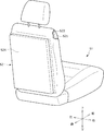
- the vehicle seat S according to the present embodiment has the appearance shown in FIG. It should be noted that in FIG. 1, a part of the vehicle seat S, specifically, the right end portions of the seat cushion S1 and the seat back S2 is configured by removing the cushion skin S12 and the back skin S22 for convenience of description. Illustrated.
- the vehicle seat S is arranged on a seat cushion S1 that serves as a seating portion that supports the buttocks of the seated person, a seat back S2 that serves as a backrest portion that supports the back of the seated person, and an upper portion of the seat back S2.
- a headrest S3 Has a main component.
- the seat cushion S1 is configured by placing a cushion pad S11 on a cushion frame (not shown), and further covering the cushion pad S11 with a cushion skin S12.
- the seat back S2 is configured by placing a back pad S21 on a back frame S23 described later and further covering the back pad S21 with a back skin S22. As shown in FIG. 2, a back board S24 is attached and closed on the back surface located behind the seat back S2. FIG. 3 shows a state of the seatback S2 with the backboard S24 removed.
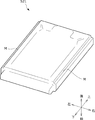
- the back pad S21 of the seat back S2 includes a pair of groove portions M extending in the vertical direction of the vehicle seat at both ends in the seat width direction. More specifically, the back pad S21 includes a pair of groove portions M extending in the up-down direction of the vehicle seat at the rear of the vehicle seat in the front-rear direction and at both ends in the seat width direction.
- a second fixing member 20 of a skin fixing device K described later is attached along the groove M.
- the cushion pad S11 and the back pad S21 are made of an elastic cushion material such as urethane foam, and the cushion skin S12 and the back skin S22 are made of synthetic leather or cloth and are formed by sewing a plurality of skin materials. ..
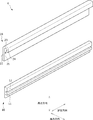
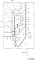
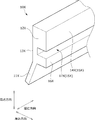
- FIG. 5A is a perspective view showing the skin fixing device K
- FIG. 5B is an explanatory view showing the structure of the first fixing member 10
- FIG. 5C is an explanatory view showing the structure of the second fixing member 20.
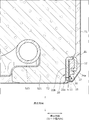
- FIG. 6 is a diagram showing an AA cross section of FIG.
- the back skin S22 includes a first skin T1 and a second skin T2.
- the skin fixing device K of the present embodiment includes, as main components, a first fixing member 10 connected to the first skin T1 and a second fixing member 20 attached to a back pad S21 as a member to be fixed. Is configured.
- the first fixing member 10 and the second fixing member 20 are a pair of corresponding elongated members, and can be formed of, for example, a resin material such as polypropylene.
- First fixing member 10 As shown in FIGS. 5A, 5B and 6, the first fixing member 10 is connected to the first skin T1 at the first connecting portion 11 at one end, and the insertion portion 12 is formed at the other end. (The first skin T1 is sewn to the first connecting portion 11 at the suture line h).
- the thickness direction of the first fixing member 10 is a direction orthogonal to the extending direction of the first fixing member 10.
- the height direction of the first fixing member 10 is a direction orthogonal to the thickness direction and the extending direction of the first fixing member 10.
- the first fixing member 10 has a substantially F shape when viewed from the end.
- the first connecting portion 11 is formed thinner than the insertion portion 12 in the thickness direction of the first fixing member 10. Since the thickness of the first connecting portion 11 is smaller than the thickness of the inserting portion 12, the first fixing member 10 and the first skin T1 can be easily connected at the first connecting portion 11.
- the insertion portion 12 is formed such that the surface on the first skin T1 side is substantially parallel to the surface on the opposite side to the first skin T1. More specifically, the insertion portion 12 has a skin contact surface 13 that contacts the first skin T1 on one surface in the thickness direction of the first fixing member 10. In addition, the insertion portion 12 has a protruding surface 14 that protrudes to the surface opposite to the skin contact surface 13. Then, as shown in FIGS. 5B and 6, the skin contact surface 13 and the protruding surface 14 are substantially parallel to each other. In this way, by making the insertion portion 12 project to the side opposite to the first skin T1, the skin contact surface 13 can be made flat, and the first fixing member 10 is inserted into the second fixing member 20. It's getting easier.
- the first fixing member 10 has a first locking portion 16 protruding between the insertion portion 12 and the first connecting portion 11 on the same side as the protruding surface 14 in the height direction.
- the insertion portion 12 of the first fixing member 10 has a rotation restricting portion 15 with respect to the holding portion 21.
- the rotation restricting portion 15 is configured to include the protruding surface 14 and the recessed portion 17 of the insertion portion 12.
- the recess 17 is provided between the insertion portion 12 and the first locking portion 16 and is formed so as to be recessed in the direction from the protruding surface 14 toward the skin contact surface 13.
- the insertion part 12 is formed to be larger than the first locking part 16 in the height direction of the first fixing member 10.
- the second fixing member 20 is arranged in the groove portion M of the back pad S21 as the member to be fixed, and is provided along the first fixing member 10.
- the second fixing member 20 has a holding portion 21 that holds the insertion portion 12 of the first fixing member 10.
- the holding portion 21 has a base portion 22 that is in contact with and supported by the groove portion M, an extending portion 23 that extends from the base portion 22 in the thickness direction of the first fixing member 10, and an extending portion 23. It has a second locking portion 24 that is bent from and extends substantially parallel to the base portion 22.
- the second locking portion 24 has a locking end portion 24 a that locks the insertion portion 12.
- the locking end portion 24a is formed so as to be bent from the second locking portion 24 toward the holding portion 21, in other words, in the thickness direction toward the base portion 22.
- the second fixing member 20 is connected to the second skin T2 different from the first skin T1 at the second connecting portion 22a (the second skin T2 is sewn to the second connecting portion 22a). sewn on h).
- a first bending part 25 is formed between the base part 22 and the extending part 23, and between the extending part 23 and the second locking part 24.
- the second curved portion 26 is formed. If the radius of curvature of the first bending portion 25 is larger than that of the second bending portion 26, the engagement state of the insertion portion 12 in the holding portion 21 becomes stable, which is preferable.
- the contact surface 22b where the second fixing member 20 contacts the back pad S21 as the member to be fixed includes the insertion portion 12 and the back frame S23 (a pipe that constitutes the seat back S2 and extends in the vertical direction). It is arranged between the frame). According to such a configuration, when the insertion portion 12 is inserted into the holding portion 21 and the insertion portion 12 is pulled by the first skin T1, the force applied to the second fixing member 20 is supported by the back frame S23. To be done. Therefore, the engagement state between the first fixing member 10 and the second fixing member 20 is stably supported.
- FIGS. 7A and 7B are enlarged views showing a cross section taken along the line AA of FIG. 3, and are views for explaining a process of engaging the first fixing member 10 with the second fixing member 20 according to the present embodiment. is there.
- FIG. 7B in the thickness direction of the first fixing member 10 (corresponding to the sheet width direction), the insertion portion 12 is fitted and held by the holding portion 21.
- the first skin T1 is fixed to the back pad S21 by inserting and engaging the insertion portion 12 with the holding portion 21.
- the insertion portion 12 of the first fixing member 10 has the rotation restricting portion 15 (specifically, the protruding surface 14 and the concave portion 17) with respect to the holding portion 21. According to such a configuration, the increase in size in a predetermined direction (the thickness direction of the first fixing member 10) is suppressed. Further, the insertion portion 12 is prevented from falling off the holding portion 21 when the first fixing member 10 is pulled in the rotation direction. Specifically, since the insertion portion 12 is fitted and held in the holding portion 21, the insertion portion 12 may drop from the holding portion 21 when the first fixing member 10 is pulled in the rotation direction. Suppressed.
- the second fixing member 20 is provided with an end portion arranged on the side facing the protruding surface 14 in a state where the insertion portion 12 is held by the holding portion 21, from the second locking portion 24 to the first fixing member 10 side.
- the locking end portion 24a is formed so as to project to the outside.
- the locking end portion 24 a fits into the recess 17 between the insertion portion 12 and the first locking portion 16.
- the rotation restricting portion 15 specifically, the protruding surface 14
- restricts the rotation of the first fixing member 10 restricts the rotation of the first fixing member 10
- the second fixing member 20 fits into the recess 17 of the first fixing member 10. By doing so, it becomes more difficult for the first fixing member 10 to come off from the second fixing member 20.
- the surface on the first skin T1 side has the first skin T1 and the second skin T2 interposed therebetween.
- the surface adjacent to the base 22 and opposite to the first skin T1 is in contact with the second locking portion 24.
- the second skin T2 is disposed between the first fixing member 10 and the second fixing member 20
- the insertion portion 12 and the holding portion 21 extend to a position where they overlap.
- the gap of the holding portion 21 that may occur between the insertion portion 12 and the holding portion 21 when the insertion portion 12 is inserted can be filled with the second skin T2, and the holding portion 21 and the holding portion 21 can be held.
- the engaging force of the portion 21 can be increased.
- the first skin T1 and the second skin T1 are provided between the second fixing member 20 and the first fixing member 10.
- the epidermis T2 is inserted.
- an elastic slab is provided as a back cloth (not shown) on the back surface side of at least one of the first skin T1 and the second skin T2.
- FIG. 8 is explanatory drawing which shows the cross section of the 1st fixing member 10X which concerns on the modification of embodiment of this invention.
- the first connecting portion 11X is bent on the side opposite to the protruding direction of the insertion portion 12X.
- the first connecting portion 11X of the insertion portion 12X is bent while the insertion portion 12X of the first fixing member 10X is held in the holding portion 21 of the second fixing member 20. Due to the repulsive force due to, the locking force between the first locking portion 16 of the insertion portion 12X and the second locking portion 24 (locking end portion 24a) of the holding portion 21 is improved.
- the first connecting portion 11X is bent at the boundary between the first locking portion 16X and the first connecting portion 11X, it is easily bent when a force is input. Since the end portion of the first connecting portion 11X projects toward the first skin T1 side in the thickness direction from the skin contact surface 13X, the first fixing member 10X according to the modified example is held by the second fixing member 20. In this state, filling the gap with the second fixing member 20 suppresses the gap from being exposed.
- the skin fixing device K is used to fix the back skin S22 of the seat back S2 to the back pad S21, but the skin fixing device K is used as the cushion skin S12 of the seat cushion S1. Can also be used for fixing to the cushion pad S11.
- the skin fixing device K according to the present embodiment is not limited in its application site as long as it is arranged in the groove portion of the member to be fixed such as the cushion pad S11 and the back pad S21.
- the skin fixing device according to the present embodiment has been described by taking a vehicle seat mounted on a vehicle as an example.
- the application of the skin fixing device according to the present embodiment is not limited to the vehicle seat, and the application is not particularly limited as long as the seat is configured by covering the pad member with the cover member.
- the skin fixing device of the present invention can be used for a normal seat used in a facility or a building, or a vehicle seat used in a vehicle other than a vehicle.
- the epidermal fixing device according to the present embodiment can be applied to other than the seat as long as the epidermis is fixed to the fixed member, for example, it is also applied to furniture such as beds and sofas. It is possible.
Landscapes
- Engineering & Computer Science (AREA)
- Mechanical Engineering (AREA)
- Aviation & Aerospace Engineering (AREA)
- Transportation (AREA)
- Manufacturing & Machinery (AREA)
- Seats For Vehicles (AREA)
Abstract
車両用シートの幅方向など、所定の方向において大型化することを抑制しつつ、表皮の端部に設けた固定部材が被固定部材から脱落してしまうことが防止された表皮固定装置及び乗物用シートを提供する。 一端部の第1連結部11において第1表皮T1と連結され、他端部に挿入部12が形成された板状の第1固定部材10と、被固定部材S21の溝部Mに配置され、第1固定部材10に沿って設けられるとともに、挿入部12を保持する保持部21を有する第2固定部材20と、を備え、挿入部12が保持部21に挿入されて係合することにより、第1表皮T1が被固定部材S21に対して固定され、第1固定部材10の挿入部12は、保持部21に対する回転規制部15を有している表皮固定装置K。
Description
本発明は、表皮固定装置及び乗物用シートに係り、特に、パッド部材を覆う表皮を固定するための表皮固定装置を有する乗物用シートに関する。
一般に、車両用シートにおいて、乗員の臀部及び大腿部を支持する着座部であるシートクッションや乗員の背部を支持する背もたれ部であるシートバックは、シートフレームにパッド部材を載置し、表皮を被覆することにより形成されている。
このような車両用シートにおける表皮端末の係止は、例えば、特許文献1に記載されているように、表皮の端部に沿って設けられた固定部材を被固定部材の溝部に挿入して、固定部材の係止部を被固定部材の係止部に引っ掛けて固定する技術が知られている。このとき、固定部材の回転防止部が、被固定部材の回転防止壁に突き当たった状態とされることで表皮が被固定部材に固定される。
しかし、上述のような表皮固定装置においては、回転防止部が固定部材の厚み方向、具体的には、車両用シートの幅方向において係止部とは反対側に配置されるため、車両用シートの幅方向(換言すると、固定部材の厚み方向)において大型化していた。よって、車両用シートの幅方向など、所定の方向において固定部材が大型化することを抑制した表皮固定装置が望まれていた。
本発明は、上記の課題に鑑みてなされたものであり、その目的は、車両用シートの幅方向など、所定の方向において大型化することを抑制しつつ、表皮の端部に設けた固定部材が被固定部材から脱落してしまうことが防止された表皮固定装置及び乗物用シートを提供することにある。
前記課題は、本発明の表皮固定装置によれば、一端部の第1連結部において第1表皮と連結され、他端部に挿入部が形成された板状の第1固定部材と、被固定部材の溝部に配置され、前記第1固定部材に沿って設けられるとともに、前記挿入部を保持する保持部を有する第2固定部材と、を備え、前記挿入部が前記保持部に挿入されて係合することにより、前記第1表皮が前記被固定部材に対して固定され、前記第1固定部材の前記挿入部は、前記保持部に対する回転規制部を有していること、により解決される。
上記のように構成された本発明の表皮固定装置では、挿入部が保持部に対する回転規制部を有することで、所定の方向において大型化することが抑制されつつ、第1固定部材が回転方向に引っ張られた際に挿入部が保持部から脱落することが抑制される。
また、上記の構成において、前記第1固定部材の厚み方向において、前記挿入部は前記保持部と嵌合して保持されるとよい。
上記の構成では、挿入部が保持部に対して嵌合して保持されるため、第1固定部材が回転方向に引っ張られた際に挿入部が保持部から脱落することが抑制される。
上記の構成では、挿入部が保持部に対して嵌合して保持されるため、第1固定部材が回転方向に引っ張られた際に挿入部が保持部から脱落することが抑制される。
また、上記の構成において、前記挿入部は、前記第1固定部材の厚み方向における一方の面に前記第1表皮と当接する表皮当接面を有し、前記表皮当接面とは反対側の面に突出する突出面を有するとよい。
上記の構成では、挿入部を第1表皮とは反対側に突出させることで、表皮当接面をフラットにすることができ、第1固定部材を第2固定部材へと挿入しやすくなる。
上記の構成では、挿入部を第1表皮とは反対側に突出させることで、表皮当接面をフラットにすることができ、第1固定部材を第2固定部材へと挿入しやすくなる。
また、上記の構成において、前記第1固定部材は、前記挿入部と前記第1連結部との間に前記突出面と同じ側に突出する第1係止部を有し、前記第2固定部材は、前記挿入部が前記保持部に保持されている状態において前記突出面と対向する側に配置される端部に、前記第1固定部材の側に突出して形成された係止端部を有し、前記係止端部は、前記挿入部と前記第1係止部との間の凹部と嵌合するとよい。
上記の構成では、回転規制部で第1固定部材の回転を規制しつつ、第2固定部材が第1固定部材の凹部と嵌合することで、より一層第1固定部材が第2固定部材から外れにくくなる。
上記の構成では、回転規制部で第1固定部材の回転を規制しつつ、第2固定部材が第1固定部材の凹部と嵌合することで、より一層第1固定部材が第2固定部材から外れにくくなる。
また、上記の構成において、前記保持部は、前記溝部と当接して支持される基部と、前記基部から前記第1固定部材の厚み方向に延在する延在部と、前記延在部から屈曲して前記基部と略平行に延在して前記挿入部を係止する第2係止部を有し、前記挿入部は、前記第1表皮の側の面が前記第1表皮とは反対側の面と略平行に形成されており、前記挿入部は、前記基部と前記第2係止部との間において、前記第1表皮の側の面が前記基部と当接するとともに、前記第1表皮とは反対側の面が前記第2係止部と当接するとよい。
上記の構成では、保持部と挿入部の略平行な面同士が当接することでより挿入部が回転するための隙間がなくなる。
上記の構成では、保持部と挿入部の略平行な面同士が当接することでより挿入部が回転するための隙間がなくなる。
また、上記の構成において、前記第1連結部は、厚み方向において、前記挿入部よりも薄く形成されているとよい。
上記の構成では、第1連結部の厚みが挿入部の厚みよりも薄いことにより、第1固定部材と第1表皮を第1連結部において連結しやすくなる。
上記の構成では、第1連結部の厚みが挿入部の厚みよりも薄いことにより、第1固定部材と第1表皮を第1連結部において連結しやすくなる。
また、上記の構成において、前記第2固定部材は、前記第1表皮とは異なる第2表皮と第2連結部において連結されており、前記第2表皮は、前記第1固定部材と前記第2固定部材の間に配置され、前記第1固定部材の高さ方向において前記挿入部と前記保持部とが重なる位置まで延在しているとよい。
上記の構成では、挿入部を保持部へ挿入したときに挿入部と保持部の隙間を第2表皮で埋めることができ、挿入部と保持部の係合力を高めることができる。
上記の構成では、挿入部を保持部へ挿入したときに挿入部と保持部の隙間を第2表皮で埋めることができ、挿入部と保持部の係合力を高めることができる。
また、上記の構成において、前記第2固定部材と、前記第1固定部材との間に前記第1表皮と前記第2表皮が挿入されており、前記第1表皮及び前記第2表皮のうち少なくとも一方の裏面側に弾性的なスラブが裏布として設けられているとよい。
上記の構成では、挿入部が保持部に挿入された状態において、挿入部と保持部の間の隙間が弾性的なスラブによって、弾性的に吸収される。
上記の構成では、挿入部が保持部に挿入された状態において、挿入部と保持部の間の隙間が弾性的なスラブによって、弾性的に吸収される。
また、上記の構成において、前記第1固定部材の前記第1連結部は、前記挿入部の突出方向とは反対側に屈曲しているとよい。
上記の構成では、挿入部が保持部内に保持された状態で、挿入部の第1連結部が屈曲していることによる反発力により、挿入部の第1係止部と保持部の係止端部との間の係止力が向上する。
上記の構成では、挿入部が保持部内に保持された状態で、挿入部の第1連結部が屈曲していることによる反発力により、挿入部の第1係止部と保持部の係止端部との間の係止力が向上する。
また、本発明の乗物用シートによれば、上記の表皮固定装置と、シートバックと、シートクッションと、を備え、前記シートバックは、バックフレームと、前記バックフレームに載置されたバックパッドと、前記バックパッドを覆うバック表皮と、を有し、前記シートクッションは、クッションフレームと、前記クッションフレームに載置されたクッションパッドと、前記クッションパッドを覆うクッション表皮と、を有し、前記被固定部材は、前記バックパッド又は前記クッションパッドであり、前記第2固定部材が前記被固定部材と接する当接面は、前記挿入部と前記バックフレーム又は前記クッションフレームとの間に配置されること、により解決される。
上記のように構成された本発明の乗物用シートでは、挿入部が保持部に挿入された状態において、挿入部が表皮に引っ張られる場合に、第2固定部材にかかる力がフレームにより支持される。
上記のように構成された本発明の乗物用シートでは、挿入部が保持部に挿入された状態において、挿入部が表皮に引っ張られる場合に、第2固定部材にかかる力がフレームにより支持される。
本発明の表皮固定装置によれば、挿入部が保持部に対する回転規制部を有することで、所定の方向において固定部材が大型化することが抑制されつつ、第1固定部材が回転方向に引っ張られた際に挿入部が保持部から脱落することが抑制される。
また、本発明の表皮固定装置によれば、挿入部が保持部に対して嵌合して保持されるため、第1固定部材が回転方向に引っ張られた際に挿入部が保持部から脱落することが抑制される。
また、本発明の表皮固定装置によれば、挿入部を第1表皮とは反対側に突出させることで、表皮当接面をフラットにすることができ、第1固定部材を第2固定部材へと挿入しやすくなる。
また、本発明の表皮固定装置によれば、回転規制部で第1固定部材の回転を規制しつつ、第2固定部材が第1固定部材の凹部と嵌合することで、より一層第1固定部材が第2固定部材から外れにくくなる。
また、本発明の表皮固定装置によれば、保持部と挿入部の略平行な面同士が当接することでより挿入部が回転するための隙間がなくなる。
また、本発明の表皮固定装置によれば、第1連結部の厚みが挿入部の厚みよりも薄いことにより、第1固定部材と第1表皮を第1連結部において連結しやすくなる。
また、本発明の表皮固定装置によれば、挿入部を保持部へ挿入したときに挿入部と保持部の隙間を第2表皮で埋めることができ、挿入部と保持部の係合力を高めることができる。
また、本発明の表皮固定装置によれば、挿入部が保持部内に保持された状態で、挿入部の第1連結部が屈曲していることによる反発力により、挿入部の第1係止部と保持部の係止端部との間の係止力が向上する。
また、本発明の表皮固定装置によれば、挿入部が保持部に挿入された状態において、挿入部と保持部の間の隙間が弾性的なスラブによって、弾性的に吸収される。
本発明の乗物用シートによれば、挿入部が保持部に挿入された状態において、挿入部が表皮に引っ張られる場合に、第2固定部材にかかる力がフレームにより支持される。
以下、図1乃至図8を参照しながら、本発明の実施の形態(以下、本実施形態)に係る乗物用シートについて説明する。本実施形態に係る乗物用シートとして、車両に搭載される車両用シートを例に挙げて説明することとするが車両用シートに限定されるものではない。
なお、以下に説明する実施形態は、本発明の理解を容易にするための一例に過ぎず、本発明を限定するものではない。すなわち、以下に説明する部材の形状、寸法、配置等については、本発明の趣旨を逸脱することなく、変更、改良され得るとともに、本発明にはその等価物が含まれることは勿論である。
以下の説明中、「前後方向」とは、車両用シートの着座者から見たときの前後方向を意味し、車両の走行方向と一致する方向である。「シート幅方向」とは、車両用シートの横幅方向を意味し、車両用シートの着座者から見たときの左右方向と一致する。また、「上下方向」とは、車両用シートの高さ方向を意味し、車両用シートを正面から見たときの上下方向と一致している。「シート内側方向」とは、車両用シートの内側方向(車両用シートの中央に向かう方向)を意味しする。
[1.車両用シートSの構成]
本実施形態に係る車両用シートSは、図1に図示した外観を有している。なお、図1中、車両用シートSの一部、具体的には、シートクッションS1及びシートバックS2の右端部については、説明の都合上、クッション表皮S12及びバック表皮S22を外した構成にて図示している。
本実施形態に係る車両用シートSは、図1に図示した外観を有している。なお、図1中、車両用シートSの一部、具体的には、シートクッションS1及びシートバックS2の右端部については、説明の都合上、クッション表皮S12及びバック表皮S22を外した構成にて図示している。
車両用シートSは、着座者の臀部を支える着座部分となるシートクッションS1、着座者の背部を支える背もたれ部分となるシートバックS2、及び、シートバックS2の上部に配置され、着座者の頭部を支えるヘッドレストS3を主な構成要素として有する。シートクッションS1は、不図示のクッションフレームにクッションパッドS11を載置し、更にクッションパッドS11をクッション表皮S12で覆うことで構成されている。
シートバックS2は、後述のバックフレームS23にバックパッドS21を載置し、更にバックパッドS21をバック表皮S22で覆うことで構成されている。図2に示すように、シートバックS2の後方に位置する裏面は、バックボードS24が取り付けられ塞がれている。図3は、バックボードS24を取り外した状態のシートバックS2の状態を示している。
図4に示すように、シートバックS2のバックパッドS21は、シート幅方向の両端部に、乗物用シートの上下方向に延在する一対の溝部Mを備えている。より詳細には、バックパッドS21は、乗物用シートの前後方向における後方、かつ、シート幅方向の両端部に、乗物用シートの上下方向に延在する一対の溝部Mを備えている。この溝部Mに沿うようにして、後述する表皮固定装置Kの第2固定部材20が取り付けられる。
クッションパッドS11及びバックパッドS21は、ウレタンフォームなどの弾性を有するクッション材からなり、クッション表皮S12及びバック表皮S22は、合成皮革や布地などからなり、複数の表皮材が縫製されて形成されている。
[2.表皮固定装置の構成]
以下、本実施形態に係る車両用シートSが備えるシートバックS2のバック表皮S22をバックパッドS21に対して固定する表皮固定装置Kについて、図5A乃至図6を参照しながら説明する。図5Aは、表皮固定装置Kを示す斜視図であり、図5Bは、第1固定部材10の構成を示す説明図であり、図5Cは、第2固定部材20の構成を示す説明図である。図6は、図3のA-A断面を示す図である。
以下、本実施形態に係る車両用シートSが備えるシートバックS2のバック表皮S22をバックパッドS21に対して固定する表皮固定装置Kについて、図5A乃至図6を参照しながら説明する。図5Aは、表皮固定装置Kを示す斜視図であり、図5Bは、第1固定部材10の構成を示す説明図であり、図5Cは、第2固定部材20の構成を示す説明図である。図6は、図3のA-A断面を示す図である。
以下で詳述するように、バック表皮S22は、第1表皮T1と第2表皮T2を備えている。本実施形態の表皮固定装置Kは、第1表皮T1と連結された第1固定部材10と、被固定部材としてのバックパッドS21に取り付けられた第2固定部材20と、を主構成要素として備えて構成されている。第1固定部材10及び第2固定部材20は対応する一対の長尺状部材であり、例えば、ポリプロピレン等の樹脂材料で形成することが可能である。
(第1固定部材10)
第1固定部材10は、図5A、図5B及び図6に示すように、一端部の第1連結部11において第1表皮T1と連結され、他端部に挿入部12が形成された長尺の板状部材である(第1連結部11に第1表皮T1が縫合線hで縫着されている)。ここで、第1固定部材10の厚み方向とは、第1固定部材10の延在方向と直交する方向である。また、第1固定部材10の高さ方向とは、第1固定部材10の厚み方向及び延在方向と直交する方向である。
第1固定部材10は、図5A、図5B及び図6に示すように、一端部の第1連結部11において第1表皮T1と連結され、他端部に挿入部12が形成された長尺の板状部材である(第1連結部11に第1表皮T1が縫合線hで縫着されている)。ここで、第1固定部材10の厚み方向とは、第1固定部材10の延在方向と直交する方向である。また、第1固定部材10の高さ方向とは、第1固定部材10の厚み方向及び延在方向と直交する方向である。
第1固定部材10は、端面視略F字形状を有している。第1連結部11は、第1固定部材10の厚み方向において、挿入部12よりも薄く形成されている。第1連結部11の厚みが挿入部12の厚みよりも薄いことにより、第1固定部材10と第1表皮T1を第1連結部11において連結しやすくなっている。
図6に示すように、挿入部12は、第1表皮T1の側の面が第1表皮T1とは反対側の面と略平行に形成されている。より詳細には、挿入部12は、第1固定部材10の厚み方向における一方の面に第1表皮T1と当接する表皮当接面13を有している。また、挿入部12は、表皮当接面13とは反対側の面に突出する突出面14を有している。そして、図5B及び図6に示すように、表皮当接面13と突出面14が略平行となっている。このように、挿入部12を第1表皮T1とは反対側に突出させることで、表皮当接面13をフラットにすることができ、第1固定部材10を第2固定部材20へと挿入しやすくなっている。
図5Bに示すように、第1固定部材10は、その高さ方向において、挿入部12と第1連結部11との間に突出面14と同じ側に突出する第1係止部16を有している。第1固定部材10の挿入部12は、保持部21に対する回転規制部15を有している。ここで、回転規制部15は、挿入部12の突出面14及び凹部17を備えて構成されている。なお、凹部17は、挿入部12と第1係止部16との間に設けられ、突出面14から表皮当接面13に向かう方向に窪んで形成されたものである。第1固定部材10の高さ方向において、挿入部12は、第1係止部16よりも大きく形成されている。
(第2固定部材20)
第2固定部材20は、図5B、図5C及び図6に示すように、被固定部材としてのバックパッドS21の溝部Mに配置され、第1固定部材10に沿って設けられている。第2固定部材20は、第1固定部材10の挿入部12を保持する保持部21を有している。
第2固定部材20は、図5B、図5C及び図6に示すように、被固定部材としてのバックパッドS21の溝部Mに配置され、第1固定部材10に沿って設けられている。第2固定部材20は、第1固定部材10の挿入部12を保持する保持部21を有している。
保持部21は、図5Cに示すように、溝部Mと当接して支持される基部22と、基部22から第1固定部材10の厚み方向に延在する延在部23と、延在部23から屈曲して基部22と略平行に延在する第2係止部24を有している。第2係止部24は、挿入部12を係止する係止端部24aを有している。係止端部24aは、第2係止部24から、保持部21に向かう方向、換言すると、厚み方向において基部22に向かう方向に曲折するようにして形成されている。図6に示すように、第2固定部材20は、第1表皮T1とは異なる第2表皮T2と第2連結部22aにおいて連結されている(第2連結部22aに第2表皮T2が縫合線hで縫着される)。
図5Cに示すように、保持部21において、基部22と延在部23との間には第1湾曲部25が形成されており、延在部23と第2係止部24との間には第2湾曲部26が形成されている。第1湾曲部25は第2湾曲部26よりも曲率半径が大きく形成されていると、保持部21における挿入部12の係合状態が安定したものとなるため好適である。
図6に示すように、第2固定部材20が被固定部材としてのバックパッドS21と接する当接面22bは、挿入部12とバックフレームS23(シートバックS2を構成する上下方向に延在するパイプフレーム)との間に配置されている。このような構成によれば、挿入部12が保持部21に挿入された状態において、挿入部12が第1表皮T1に引っ張られる場合に、第2固定部材20にかかる力がバックフレームS23により支持される。したがって、第1固定部材10と第2固定部材20の間の係合状態が安定して支持されることになる。
[3.表皮固定装置の作用]
以下、表皮固定装置Kの作用について、図7A及び図7Bを参照して説明をする。図7A及び図7Bは、図3のA-A断面を示す拡大図であって、本実施形態に係る第2固定部材20に対して第1固定部材10を係合する過程を説明する図である。図7Bに示すように、第1固定部材10の厚み方向(シート幅方向に対応)において、挿入部12が保持部21と嵌合して保持されている。挿入部12が保持部21に挿入されて係合することにより、第1表皮T1がバックパッドS21に対して固定される。
以下、表皮固定装置Kの作用について、図7A及び図7Bを参照して説明をする。図7A及び図7Bは、図3のA-A断面を示す拡大図であって、本実施形態に係る第2固定部材20に対して第1固定部材10を係合する過程を説明する図である。図7Bに示すように、第1固定部材10の厚み方向(シート幅方向に対応)において、挿入部12が保持部21と嵌合して保持されている。挿入部12が保持部21に挿入されて係合することにより、第1表皮T1がバックパッドS21に対して固定される。
本実施形態の表皮固定装置Kでは、第1固定部材10の挿入部12が保持部21に対する回転規制部15(詳細には、突出面14及び凹部17)を有している。このような構成によれば、所定の方向(第1固定部材10の厚み方向)において大型化することが抑制される。また、第1固定部材10が回転方向に引っ張られた際に挿入部12が保持部21から脱落することが抑制される。具体的には、挿入部12が保持部21に対して嵌合して保持されるため、第1固定部材10が回転方向に引っ張られた際に挿入部12が保持部21から脱落することが抑制される。
第2固定部材20は、挿入部12が保持部21に保持されている状態において突出面14と対向する側に配置される端部に、第2係止部24から第1固定部材10の側に突出して形成された係止端部24a備えている。係止端部24aは、挿入部12と第1係止部16との間の凹部17と嵌合する。このような構成によれば、回転規制部15(詳細には突出面14)で第1固定部材10の回転を規制しつつ、第2固定部材20が第1固定部材10の凹部17と嵌合することで、より一層、第1固定部材10が第2固定部材20から外れにくくなる。
第1固定部材10の挿入部12は、シート幅方向における基部22と第2係止部24との間において、第1表皮T1の側の面が、第1表皮T1及び第2表皮T2を介して、基部22と隣接するとともに、第1表皮T1とは反対側の面が第2係止部24と当接している。このような構成によれば、保持部21と挿入部12の略平行な面同士が当接することでより挿入部12が回転するための隙間がなくなる。
図7Bに示すように、第2固定部材20に対して第1固定部材10を係合した状態において、第2表皮T2は、第1固定部材10と第2固定部材20の間に配置され、第1固定部材10の高さ方向において挿入部12と保持部21とが重なる位置まで延在している。このような構成によれば、挿入部12を保持部21へ挿入したときに挿入部12との間に生じ得る保持部21の隙間を第2表皮T2で埋めることができ、挿入部12と保持部21の係合力を高めることができる。
図7Bに示すように、第2固定部材20に対して第1固定部材10を係合した状態において、第2固定部材20と第1固定部材10との間に、第1表皮T1と第2表皮T2が挿入されている。このとき、第1表皮T1及び第2表皮T2のうち少なくとも一方の裏面側に弾性的なスラブが裏布(不図示)として設けられていると好適である。このような構成によれば、挿入部12が保持部21に挿入された状態において、挿入部12と保持部21の間の隙間が弾性的なスラブによって、弾性的に吸収される。
[4.変形例]
本発明は上記の実施形態に限定されるものではない。以下においては、図8に基づいて、第1固定部材の変形例について説明する。図8は、本発明の実施形態の変形例に係る第1固定部材10Xの断面を示す説明図である。
本発明は上記の実施形態に限定されるものではない。以下においては、図8に基づいて、第1固定部材の変形例について説明する。図8は、本発明の実施形態の変形例に係る第1固定部材10Xの断面を示す説明図である。
図8に示されるように、変形例に係る第1固定部材10Xは、第1連結部11Xが、挿入部12Xの突出方向とは反対側に屈曲している。このような構成によれば、第1固定部材10Xの挿入部12Xが第2固定部材20の保持部21内に保持された状態において、挿入部12Xの第1連結部11Xが屈曲していることによる反発力により、挿入部12Xの第1係止部16と保持部21の第2係止部24(係止端部24a)との間の係止力が向上する。
第1連結部11Xは、第1係止部16Xと第1連結部11Xの境界で屈曲しているため、力が入力された際に曲がりやすくなっている。第1連結部11Xの端部が、厚み方向において表皮当接面13Xよりも第1表皮T1の側へと突出するため、変形例に係る第1固定部材10Xが第2固定部材20に保持された状態において、第2固定部材20との間の隙間を埋めることにより、隙間が露出することが抑制される。
上記の実施形態では、表皮固定装置KがシートバックS2のバック表皮S22をバックパッドS21に対して固定するために用いられた例を示したが、表皮固定装置KをシートクッションS1のクッション表皮S12をクッションパッドS11に対して固定するために用いることも可能である。
また、本実施形態に係る表皮固定装置Kは、クッションパッドS11やバックパッドS21などの被固定部材の溝部に配置されるのであれば、その適用部位は限定されるものではない。
以上、本実施形態に係る表皮固定装置を車両に搭載される車両用シートを例として説明した。本実施形態に係る表皮固定装置の適用は、車両用シートに限定されるものではなく、パッド部材をカバー部材により覆うことで構成されるシートであれば、特に用途についての制限はない。例えば、本発明の表皮固定装置は、施設や建物内で用いられる通常のシート、或いは車両以外の乗物内で使用される乗物用シートにも利用可能である。
さらに、本実施形態に係る表皮固定装置は、表皮を被固定部材に対して固定するのであれば、シート以外にも適用することが可能であり、例えば、ベッドやソファーなどの家具などにも応用可能である。
S 車両用シート(乗物用シート)
S1 シートクッション
S11 クッションパッド(被固定部材)
S12 クッション表皮
S2 シートバック
S21 バックパッド(被固定部材)
M 溝部
S22 バック表皮
S23 バックフレーム
S24 バックボード
S3 ヘッドレスト
K 表皮固定装置
10,10X 第1固定部材
11,11X 第1連結部
12,12X 挿入部
13,13X 表皮当接面
14,14X 突出面(回転規制部)
15,15X 回転規制部
16,16X 第1係止部
17,17X 凹部(回転規制部)
T1 第1表皮
20 第2固定部材
21 保持部
22 基部
22a 第2連結部
22b 当接面
23 延在部
24 第2係止部
24a 係止端部
25 第1湾曲部
26 第2湾曲部
T2 第2表皮
h 縫合線
Claims (10)
- 一端部の第1連結部において第1表皮と連結され、他端部に挿入部が形成された板状の第1固定部材と、
被固定部材の溝部に配置され、前記第1固定部材に沿って設けられるとともに、前記挿入部を保持する保持部を有する第2固定部材と、を備え、
前記挿入部が前記保持部に挿入されて係合することにより、前記第1表皮が前記被固定部材に対して固定され、
前記第1固定部材の前記挿入部は、前記保持部に対する回転規制部を有していることを特徴とする表皮固定装置。 - 前記第1固定部材の厚み方向において、前記挿入部は前記保持部と嵌合して保持されることを特徴とする請求項1に記載の表皮固定装置。
- 前記挿入部は、前記第1固定部材の厚み方向における一方の面に前記第1表皮と当接する表皮当接面を有し、前記表皮当接面とは反対側の面に突出する突出面を有することを特徴とする請求項1に記載の表皮固定装置。
- 前記第1固定部材は、前記挿入部と前記第1連結部との間に前記突出面と同じ側に突出する第1係止部を有し、
前記第2固定部材は、前記挿入部が前記保持部に保持されている状態において前記突出面と対向する側に配置される端部に、前記第1固定部材の側に突出して形成された係止端部を有し、
前記係止端部は、前記挿入部と前記第1係止部との間の凹部と嵌合することを特徴とする請求項3に記載の表皮固定装置。 - 前記保持部は、前記溝部と当接して支持される基部と、前記基部から前記第1固定部材の厚み方向に延在する延在部と、前記延在部から屈曲して前記基部と略平行に延在して前記挿入部を係止する第2係止部を有し、
前記挿入部は、前記第1表皮の側の面が前記第1表皮とは反対側の面と略平行に形成されており、
前記挿入部は、前記基部と前記第2係止部との間において、前記第1表皮の側の面が前記基部と当接するとともに、前記第1表皮とは反対側の面が前記第2係止部と当接することを特徴とする請求項1に記載の表皮固定装置。 - 前記第1連結部は、厚み方向において、前記挿入部よりも薄く形成されていることを特徴とする請求項1に記載の表皮固定装置。
- 前記第2固定部材は、前記第1表皮とは異なる第2表皮と第2連結部において連結されており、
前記第2表皮は、前記第1固定部材と前記第2固定部材の間に配置され、前記第1固定部材の高さ方向において前記挿入部と前記保持部とが重なる位置まで延在していることを特徴とする請求項1に記載の表皮固定装置。 - 前記第2固定部材と、前記第1固定部材との間に前記第1表皮と前記第2表皮が挿入されており、
前記第1表皮及び前記第2表皮のうち少なくとも一方の裏面側に弾性的なスラブが裏布として設けられていることを特徴とする請求項7に記載の表皮固定装置。 - 前記第1固定部材の前記第1連結部は、前記挿入部の突出方向とは反対側に屈曲していることを特徴とする請求項1に記載の表皮固定装置。
- 請求項1に記載の表皮固定装置と、
シートバックと、
シートクッションと、を備え、
前記シートバックは、バックフレームと、前記バックフレームに載置されたバックパッドと、前記バックパッドを覆うバック表皮と、を有し、
前記シートクッションは、クッションフレームと、前記クッションフレームに載置されたクッションパッドと、前記クッションパッドを覆うクッション表皮と、を有し、
前記被固定部材は、前記バックパッド又は前記クッションパッドであり、
前記第2固定部材が前記被固定部材と接する当接面は、前記挿入部と前記バックフレーム又は前記クッションフレームとの間に配置されることを特徴とする乗物用シート。
Priority Applications (2)
| Application Number | Priority Date | Filing Date | Title |
|---|---|---|---|
| US17/428,427 US11849857B2 (en) | 2019-02-06 | 2020-02-05 | Cover material fixing device and conveyance seat |
| CN202080010446.6A CN113347907A (zh) | 2019-02-06 | 2020-02-05 | 表皮固定装置及乘坐物用座椅 |
Applications Claiming Priority (2)
| Application Number | Priority Date | Filing Date | Title |
|---|---|---|---|
| JP2019-020044 | 2019-02-06 | ||
| JP2019020044A JP7436774B2 (ja) | 2019-02-06 | 2019-02-06 | 表皮固定装置及び乗物用シート |
Publications (1)
| Publication Number | Publication Date |
|---|---|
| WO2020162497A1 true WO2020162497A1 (ja) | 2020-08-13 |
Family
ID=71947076
Family Applications (1)
| Application Number | Title | Priority Date | Filing Date |
|---|---|---|---|
| PCT/JP2020/004365 Ceased WO2020162497A1 (ja) | 2019-02-06 | 2020-02-05 | 表皮固定装置及び乗物用シート |
Country Status (4)
| Country | Link |
|---|---|
| US (1) | US11849857B2 (ja) |
| JP (1) | JP7436774B2 (ja) |
| CN (1) | CN113347907A (ja) |
| WO (1) | WO2020162497A1 (ja) |
Families Citing this family (6)
| Publication number | Priority date | Publication date | Assignee | Title |
|---|---|---|---|---|
| JP7686533B2 (ja) * | 2021-10-28 | 2025-06-02 | タカノ株式会社 | 椅子の張地の係止構造 |
| JP7876182B2 (ja) * | 2022-05-12 | 2026-06-19 | デルタ工業株式会社 | シートおよび表皮固定部材 |
| JP7843255B2 (ja) * | 2023-03-22 | 2026-04-09 | 日本発條株式会社 | 表皮取付構造及び表皮取付方法 |
| TWI854843B (zh) * | 2023-09-22 | 2024-09-01 | 林育汎 | 免釘式椅套結構及其製法 |
| JPWO2025075023A1 (ja) * | 2023-10-02 | 2025-04-10 | ||
| JP2026043363A (ja) * | 2024-08-28 | 2026-03-12 | デルタ工業株式会社 | 表皮固定構造 |
Citations (7)
| Publication number | Priority date | Publication date | Assignee | Title |
|---|---|---|---|---|
| JPS62102499U (ja) * | 1985-12-19 | 1987-06-30 | ||
| JP2008006074A (ja) * | 2006-06-29 | 2008-01-17 | Inoac Corp | 発泡体用表皮、発泡体用表皮の製造方法及び超音波溶着用押さえローラ |
| JP2010005104A (ja) * | 2008-06-26 | 2010-01-14 | Toyota Boshoku Corp | 車両用シートの表皮材末端の掛け止め構造 |
| WO2011145193A1 (ja) * | 2010-05-19 | 2011-11-24 | Ykk株式会社 | シート止着具 |
| JP2013102855A (ja) * | 2011-11-11 | 2013-05-30 | Toyota Boshoku Corp | 車両用シートの表皮固定構造 |
| US20170305316A1 (en) * | 2014-09-11 | 2017-10-26 | Faurecia Automotive Seating, Llc. | Trim-cover fastener for vehicle seat |
| EP3254969A1 (en) * | 2016-06-09 | 2017-12-13 | Ningbo Geely Automobile Research & Development Co., Ltd. | Device for reduction of vertical peak acceleration |
Family Cites Families (22)
| Publication number | Priority date | Publication date | Assignee | Title |
|---|---|---|---|---|
| US3981534A (en) * | 1975-06-27 | 1976-09-21 | Universal Oil Products Company | Seat cover fastening system |
| JPS5862956U (ja) * | 1981-10-26 | 1983-04-27 | 東京シ−ト株式会社 | 表皮端末の接合構造 |
| JPH01143998U (ja) * | 1988-03-25 | 1989-10-03 | ||
| FR2700146B1 (fr) * | 1993-01-07 | 1995-03-10 | Bfa | Perfectionnements aux dispositifs d'accrochage des bords des coiffes de coussins de sièges sur les armatures de ces sièges. |
| JPH06254267A (ja) * | 1993-03-10 | 1994-09-13 | Araco Corp | ヘッドレストカバー構造 |
| CN1153115A (zh) * | 1995-12-23 | 1997-07-02 | R·施米特有限公司 | 头部靠垫 |
| FR2755594B1 (fr) * | 1996-11-14 | 1999-02-05 | Itw De France | Dispositif et procede de fixation d'un habillage de siege, et siege obtenu |
| US5820213A (en) * | 1997-07-23 | 1998-10-13 | Lear Corporation | Trim cover attachment feature |
| DE29917372U1 (de) * | 1999-10-04 | 2000-01-20 | Johnson Controls GmbH & Co. KG, 32339 Espelkamp | Befestigungselement zum Verbinden eines Polsterbezugs mit einem Polster |
| US6406093B1 (en) * | 2000-03-29 | 2002-06-18 | Lear Corporation | Attachment for seat assembly |
| JP2006298176A (ja) | 2005-04-21 | 2006-11-02 | Suzuki Motor Corp | 車両用シートのヘッドレスト構造 |
| DE102005028569B4 (de) * | 2005-06-21 | 2008-11-13 | Johnson Controls Gmbh | Profil und Anordnung zur Befestigung eines Bezugs an einem Trägerkörper, insbesondere einer Kopfstütze eines Kraftfahrzeugs sowie eine damit ausgestattete Kopfstütze |
| JP5155572B2 (ja) * | 2007-02-07 | 2013-03-06 | テイ・エス テック株式会社 | 表皮材端末処理部材,シート部品及び車両用シート |
| JP5374859B2 (ja) * | 2007-11-07 | 2013-12-25 | トヨタ紡織株式会社 | フック部材及び表皮材の係止構造 |
| US8733834B2 (en) * | 2011-04-29 | 2014-05-27 | Lear Corporation | Trim assembly |
| JP2013052757A (ja) * | 2011-09-05 | 2013-03-21 | Toyota Boshoku Corp | 車両用シート |
| JP5740480B2 (ja) * | 2011-10-06 | 2015-06-24 | Ykk株式会社 | シート止着具 |
| JP5754354B2 (ja) * | 2011-11-15 | 2015-07-29 | トヨタ紡織株式会社 | 車両用シート |
| US9027994B2 (en) * | 2012-12-31 | 2015-05-12 | Ts Tech Co., Ltd. | Locking structure for skin terminals of vehicle seat and vehicle seat provided with locking structure |
| US9981580B2 (en) * | 2015-10-26 | 2018-05-29 | Tachi-S Co., Ltd. | Seat for vehicle |
| CN207617579U (zh) * | 2018-03-29 | 2018-07-17 | 明天塑料(上海)有限公司 | 无纺布支架连接组件 |
| CN207617578U (zh) * | 2018-03-29 | 2018-07-17 | 明天塑料(上海)有限公司 | 汽车座椅面套连接组件 |
-
2019
- 2019-02-06 JP JP2019020044A patent/JP7436774B2/ja active Active
-
2020
- 2020-02-05 CN CN202080010446.6A patent/CN113347907A/zh active Pending
- 2020-02-05 WO PCT/JP2020/004365 patent/WO2020162497A1/ja not_active Ceased
- 2020-02-05 US US17/428,427 patent/US11849857B2/en active Active
Patent Citations (7)
| Publication number | Priority date | Publication date | Assignee | Title |
|---|---|---|---|---|
| JPS62102499U (ja) * | 1985-12-19 | 1987-06-30 | ||
| JP2008006074A (ja) * | 2006-06-29 | 2008-01-17 | Inoac Corp | 発泡体用表皮、発泡体用表皮の製造方法及び超音波溶着用押さえローラ |
| JP2010005104A (ja) * | 2008-06-26 | 2010-01-14 | Toyota Boshoku Corp | 車両用シートの表皮材末端の掛け止め構造 |
| WO2011145193A1 (ja) * | 2010-05-19 | 2011-11-24 | Ykk株式会社 | シート止着具 |
| JP2013102855A (ja) * | 2011-11-11 | 2013-05-30 | Toyota Boshoku Corp | 車両用シートの表皮固定構造 |
| US20170305316A1 (en) * | 2014-09-11 | 2017-10-26 | Faurecia Automotive Seating, Llc. | Trim-cover fastener for vehicle seat |
| EP3254969A1 (en) * | 2016-06-09 | 2017-12-13 | Ningbo Geely Automobile Research & Development Co., Ltd. | Device for reduction of vertical peak acceleration |
Also Published As
| Publication number | Publication date |
|---|---|
| US20220104633A1 (en) | 2022-04-07 |
| CN113347907A (zh) | 2021-09-03 |
| JP2020124442A (ja) | 2020-08-20 |
| JP7436774B2 (ja) | 2024-02-22 |
| US11849857B2 (en) | 2023-12-26 |
Similar Documents
| Publication | Publication Date | Title |
|---|---|---|
| JP7436774B2 (ja) | 表皮固定装置及び乗物用シート | |
| JP7480741B2 (ja) | シート装置 | |
| JP6475278B2 (ja) | 車両用シート | |
| JP7509075B2 (ja) | シート装置 | |
| CN104780812B (zh) | 交通工具座椅 | |
| US9573503B2 (en) | Vehicle seat | |
| US20140117738A1 (en) | Vehicle seat | |
| JP5567148B2 (ja) | 車両用シートのシートクッション | |
| US11013342B2 (en) | Conveyance seat and seat cover for the same | |
| JP6380118B2 (ja) | ヘッドレスト | |
| JP7313798B2 (ja) | 乗物用シート | |
| CN114475381B (zh) | 交通工具用座椅 | |
| JP7608280B2 (ja) | 車両用シート | |
| JP6533156B2 (ja) | 車両用シート | |
| JP7246164B2 (ja) | 背もたれ及びこれを備えた椅子 | |
| JP7602711B2 (ja) | 乗物用シート | |
| JP7701594B2 (ja) | シート | |
| JP2023181480A (ja) | シート | |
| JP4591196B2 (ja) | 車両用シート | |
| JP2018016095A (ja) | 車両のシート | |
| JP6702033B2 (ja) | 乗物用シート | |
| JP2022073407A (ja) | 椅子の構造物および椅子 | |
| JP5377891B2 (ja) | シート用クッションパッド | |
| JP2005185350A (ja) | 車両用シート | |
| JP4896478B2 (ja) | ネットシート |
Legal Events
| Date | Code | Title | Description |
|---|---|---|---|
| 121 | Ep: the epo has been informed by wipo that ep was designated in this application |
Ref document number: 20752023 Country of ref document: EP Kind code of ref document: A1 |
|
| NENP | Non-entry into the national phase |
Ref country code: DE |
|
| 122 | Ep: pct application non-entry in european phase |
Ref document number: 20752023 Country of ref document: EP Kind code of ref document: A1 |