WO2020155535A1 - 一种装配式墙体的机械辅助设备 - Google Patents
一种装配式墙体的机械辅助设备 Download PDFInfo
- Publication number
- WO2020155535A1 WO2020155535A1 PCT/CN2019/093049 CN2019093049W WO2020155535A1 WO 2020155535 A1 WO2020155535 A1 WO 2020155535A1 CN 2019093049 W CN2019093049 W CN 2019093049W WO 2020155535 A1 WO2020155535 A1 WO 2020155535A1
- Authority
- WO
- WIPO (PCT)
- Prior art keywords
- module
- lifting
- mechanical auxiliary
- auxiliary equipment
- turning
- Prior art date
Links
Images


Classifications
-
- E—FIXED CONSTRUCTIONS
- E04—BUILDING
- E04G—SCAFFOLDING; FORMS; SHUTTERING; BUILDING IMPLEMENTS OR AIDS, OR THEIR USE; HANDLING BUILDING MATERIALS ON THE SITE; REPAIRING, BREAKING-UP OR OTHER WORK ON EXISTING BUILDINGS
- E04G21/00—Preparing, conveying, or working-up building materials or building elements in situ; Other devices or measures for constructional work
- E04G21/14—Conveying or assembling building elements
- E04G21/16—Tools or apparatus
- E04G21/162—Handles to carry construction blocks
-
- E—FIXED CONSTRUCTIONS
- E04—BUILDING
- E04G—SCAFFOLDING; FORMS; SHUTTERING; BUILDING IMPLEMENTS OR AIDS, OR THEIR USE; HANDLING BUILDING MATERIALS ON THE SITE; REPAIRING, BREAKING-UP OR OTHER WORK ON EXISTING BUILDINGS
- E04G21/00—Preparing, conveying, or working-up building materials or building elements in situ; Other devices or measures for constructional work
- E04G21/14—Conveying or assembling building elements
- E04G21/16—Tools or apparatus
- E04G21/167—Tools or apparatus specially adapted for working-up plates, panels or slab shaped building elements
-
- E—FIXED CONSTRUCTIONS
- E04—BUILDING
- E04G—SCAFFOLDING; FORMS; SHUTTERING; BUILDING IMPLEMENTS OR AIDS, OR THEIR USE; HANDLING BUILDING MATERIALS ON THE SITE; REPAIRING, BREAKING-UP OR OTHER WORK ON EXISTING BUILDINGS
- E04G21/00—Preparing, conveying, or working-up building materials or building elements in situ; Other devices or measures for constructional work
- E04G21/24—Safety or protective measures preventing damage to building parts or finishing work during construction
- E04G21/26—Strutting means for wall parts; Supports or the like, e.g. for holding in position prefabricated walls
Definitions
- the embodiments of the present application relate to but are not limited to the field of construction of building materials, and particularly relate to but not limited to a mechanical auxiliary device for a fabricated wall.
- the embodiment of the application provides a mechanical auxiliary equipment for a fabricated wall, which can assist construction workers in installing walls, etc., greatly reducing the labor intensity of construction workers, improving installation efficiency of construction workers, and reducing construction costs .
- the embodiment of the present application provides a mechanical auxiliary device for a fabricated wall, including an equipment body, a gripper module, a turning module, and a lifting module,
- the turning module is mounted on the equipment body, the lifting module is mounted on the turning module, the gripping module is mounted on the lifting module through a rotating shaft, and the gripping module can rotate around the The shaft rotates;
- the turning module is configured to drive the lifting module and the gripper module to rotate around a horizontal axis along the horizontal direction
- the lifting module is configured to drive the gripper module to move in the up and down direction
- the axis of the rotation axis The direction is perpendicular to the up and down direction and perpendicular to the horizontal direction.
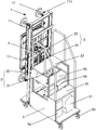
- FIG. 1 is a schematic diagram of a three-dimensional structure of a mechanical auxiliary device for a fabricated wall according to an embodiment of the application;
- FIG. 2 is a schematic diagram of another perspective three-dimensional structure of the mechanical auxiliary equipment of the fabricated wall according to the embodiment of the application;
- FIG. 3 is a schematic diagram of the front view structure of the mechanical auxiliary equipment of the fabricated wall according to an embodiment of the application;
- FIG. 4 is a schematic side view of the structure of the mechanical auxiliary equipment of the fabricated wall according to an embodiment of the application;
- Fig. 5 is a schematic top view of the mechanical auxiliary equipment of the fabricated wall according to an embodiment of the application;
- Fig. 6 is a schematic structural diagram of a hand operator of a mechanical auxiliary device for a fabricated wall according to an embodiment of the application.
- 1-handle module 11-mounting arm, 111-protrusion, 12-suction cup, 13-support frame, 14-sliding frame, 15-rotating shaft, 2-lifting module, 21-first electric cylinder, 22- Lifting bracket, 3-turning module, 31-second electric cylinder, 32-turning support, 4-third electric cylinder, 5-device body, 51-air tank, 52-vacuum pump, 53-caster, 54-battery, 55-first step, 56-second step, 57-third step, 58-tool box, 6-hand manipulator, 61-hand control button, 62-flip control button, 63-lift control button , 64-Turn the control button.
- the embodiment of the present application provides a mechanical auxiliary equipment for a fabricated wall, as shown in Figures 1 to 5, which may include an equipment body 5, a gripper module 1, a turning module 3, and a lifting module 2.
- the turning module 3 can be installed On the equipment body 5, the lifting module 2 can be installed on the turning module 3, the gripping module 1 can be installed on the lifting module 2 through a rotating shaft 15, and the gripping module 1 can be rotated around the rotating shaft 15.
- the turning module 3 can be configured to drive the lifting module 2 and the gripper module 1 installed on the lifting module 2 to rotate around a horizontal axis along the horizontal direction, and the lifting module 2 can be configured to drive the gripper module 1 to move up and down.
- the axial direction of the rotating shaft 15 can be set to be perpendicular to the up and down direction and perpendicular to the horizontal direction.
- Figure 1 shows the XYZ coordinate system.
- the horizontal direction may be the Y-axis direction, and the horizontal axis may extend along the Y-direction;
- the up-down direction may be the Z-axis direction; and
- the rotation axis 15 may extend along the X-axis.
- the lifting module 2 is mainly used to adjust the height of the gripper module 1 in the vertical direction, that is, the lifting module 2 can drive the gripper module 1 to move up and down along the Z axis.
- the turning module 3 is mainly used to control the gripper module 1 (and the lifting module 2) to perform forward tilting and resetting movements, that is, to reciprocate around the Y axis.
- the gripper module 1 can also rotate around the rotation axis 15 on the plane where it is located, that is, the gripper module 1 can reciprocate around the X axis, that is, rotate on the YZ plane.
- the wall panel to be installed can be grasped and released by the gripper module 1, and the prefabricated wall can be formed after the wall panel is installed; the height position of the wall panel can be adjusted by the lifting module 2; Adjust the posture of the gripper module 1 when grabbing the wall panel and releasing the wall panel by turning the module 3, so that the gripper module 1 can grab the inclined wall panel and place the wall panel in the desired posture; through the gripper module 1 Rotation around the rotation axis 15 can make the wall panel placed in the horizontal state (that is, the long side of the rectangular wall panel is close to the supporting surface such as the ground) and the vertical state (that is, the short side of the rectangular wall panel is close to the supporting surface such as the ground ).
- the mechanical auxiliary equipment of the fabricated wall provided by the embodiment of the application can assist the construction personnel to install the wall panels, greatly reduce the labor intensity of the construction personnel, improve the installation efficiency, and the installation quality is well guaranteed, and the The overall construction period of wall installation reduces the overall cost of construction.
- the mechanical auxiliary equipment of the prefabricated wall provided by the embodiment of the present application has a relatively simple structure, high working reliability, and long service life, which is conducive to large-scale popularization and use, and greatly improves the mechanical auxiliary equipment of the prefabricated wall of the embodiment of the present application.
- the availability of auxiliary equipment is provided.
- the gripper module 1 may include a mounting arm 11 and a suction cup 12, the mounting arm 11 may be installed on the lifting module 2, and the suction cup 12 may be installed on the mounting arm 11.
- the front part of the mounting arm 11 may be provided with a protrusion 111, and the suction cup 12 may be installed on the protrusion 111 of the mounting arm 11.
- the gripper module 1 may include two mounting arms 11, and the two mounting arms 11 are vertically arranged, and each mounting arm 11 may be provided with two upper and lower protrusions 111.
- the number of the suction cups 12 can be four, which are respectively mounted on the four protrusions 111, and the four suction cups 12 can be located on the same plane.
- the equipment body 5 may include a vacuum pump 52 for cooperating with the suction cup 12 to vacuum the space between the suction cup 12 and the wallboard, so that the suction cup 12 and the wallboard are sucked and fixed.
- the suction cup 12 may be a vacuum suction cup used in conjunction with the vacuum pump 52.
- the grip module 1 may further include a supporting frame 13, the supporting frame 13 may be installed on the lifting module 2, and the mounting arm 11 may be horizontally slidably installed on the supporting frame 13 along the Y direction.
- a guide rail extending in the Y direction may be provided on the support frame 13
- a sliding block may be provided on the mounting arm 11
- the mounting arm 11 may support The frame 13 slides along the direction of the guide rail; or, the support frame 13 can be provided with a slider, the mounting arm 11 can be provided with a guide rail extending in the Y direction, and the mounting arm 11 can slide on the support frame 13 along the guide rail direction.
- At least one mounting arm 11 is horizontally slidably mounted on the support frame along the Y direction.
- a mounting arm 11 is horizontally slidably mounted on the support frame 13.
- both mounting arms 11 can be horizontally slidably mounted on the support frame 13.
- the gripper module 1 may further include a horizontal drive assembly, which is configured to drive the horizontally slidable mounting arm 11 to move.
- the horizontal drive assembly may include a horizontal drive mechanism, which may directly drive the mounting arm 11 to slide, or the horizontal drive mechanism may drive the mounting arm 11 to slide through a transmission mechanism.
- the horizontal drive mechanism can be an electric drive mechanism (such as a linear motor, etc.) or a manual drive mechanism.
- the horizontal drive assembly includes a rotary drive mechanism and a transmission mechanism.
- the rotary drive mechanism is a manual drive mechanism or an electric drive mechanism.
- the rotating drive mechanism can be a rotating hand wheel or a rotating motor.
- the transmission mechanism can be a rack and pinion transmission mechanism or a screw nut transmission mechanism.
- the rack-and-pinion transmission mechanism or the screw-nut transmission mechanism can convert the rotational motion into linear motion to drive the mounting arm 11 to slide horizontally.
- the rack and pinion transmission mechanism may include a gear and a rack that are meshed and matched, and the gear is connected to the rotation driving mechanism, and the rack is connected to the mounting arm 11.
- the screw nut transmission mechanism may include an ordinary one-way screw and a nut, the one-way screw is connected to the rotary drive mechanism, and the nut is connected to the mounting arm 11.
- the rack and pinion transmission mechanism may include one gear and two racks, both of which mesh with the gears and are located on the gears respectively.
- the gear is connected to the rotary drive mechanism, and the two racks are respectively connected to the two mounting arms 11;
- the screw nut transmission mechanism can include a two-way screw and two nuts, both of which are mounted on the two-way screw ,
- the bidirectional screw rod is connected with the rotary drive mechanism, and two nuts are connected with the two mounting arms 11 respectively.
- the horizontal drive assembly may include a rotating hand wheel (not shown in the figure), and the rotating hand wheel and the mounting arm 11 may be connected by a screw nut transmission mechanism.
- the screw nut transmission mechanism is connected with the mounting arm 11, and the nut can be connected with only one mounting arm 11.
- the screw rod By rotating the hand wheel forward and backward, the screw rod is driven to rotate, thereby driving the mounting arm 11 to slide reciprocally on the support frame 13 to realize the distance adjustment between the two mounting arms 11.
- the screw rod may be a left-right rotation bidirectional screw rod, and two nuts may be provided on the screw rod, and the two nuts are respectively connected to the two mounting arms 11.
- the horizontal drive assembly in the grip module 1 cooperates with the support frame 13 so that the distance between the two mounting arms 11 can be adjusted. By adjusting the distance between the two mounting arms 11, it is suitable for grabbing wall panels with a width ranging from 400-1200mm.
- each mounting arm 11 can be a whole section, that is, the distance between the two suction cups 12 on one mounting arm 11 is fixed.
- the distance between the two suction cups 12 on the mounting arm 11 can be changed according to actual needs. For example, by setting the mounting arm 11 as two sections connected by a sliding rail and a sliding block, the distance between the two suction cups 12 on the mounting arm 11 can be adjusted.
- the mounting arm 11 may include a first arm and a second arm, the first arm and the second arm are slidably connected, and a suction cup 12 is provided on the first arm and the second arm.
- the first arm and the second arm can be kept relatively fixed by friction resistance, so that the distance between the two suction cups 12 on the mounting arm 11 can be maintained after adjustment.
- the distance between the two suction cups 12 on the mounting arm 11 can be adjusted by applying external force to the first arm and the second arm to overcome the frictional resistance.
- the mounting arm 11 may be located on the front side of the lifting module 1, and the supporting frame 13 may be located on the front side of the mounting arm 11.
- the position setting of the support frame 13 allows the support frame 13 to be located in the recessed position among the four suction cups 12, with a reasonable layout and compact structure, which can further reduce the length dimension (ie the dimension along the X axis) of the mechanical auxiliary equipment.
- the position of the support frame is not limited to the above.
- the support frame 13 may be located between the mounting arm 11 and the lifting module 2, that is, the support frame 13 may be located on the rear side of the mounting arm 11.
- the mechanical auxiliary equipment of the fabricated wall may further include a sliding frame 14 which can be horizontally slidably mounted on the lifting module 2, and the gripper module 1 is mounted on the sliding frame 14 via a rotating shaft 15.
- the sliding frame 14 allows the mounting arm 11 and the suction cup 12 to move in the horizontal direction (ie Y-axis direction) by ⁇ 20mm during work.
- the horizontal and vertical positions of the wall panel can be fine-tuned to facilitate the installation of the wall panel.
- a guide rail extending in the Y direction can be provided on the sliding frame 14
- a sliding block can be provided on the lifting module 2
- the sliding frame 14 can follow the guide rail on the lifting module 2
- the sliding frame 14 can be provided with a sliding block
- the lifting module 2 can be provided with a guide rail extending in the Y direction
- the sliding frame 14 can slide on the lifting module 2 along the guide rail direction.
- the mechanical auxiliary equipment of the fabricated wall may also include a horizontal holding mechanism, which may be arranged to keep the sliding frame 14 fixed.
- the horizontal holding mechanism can keep the sliding frame 14 fixed to fix the horizontal position of the gripper module 1 and the wall panel.
- An external force in the horizontal direction is applied to the sliding frame 14 to overcome the holding force of the horizontal holding mechanism, and the sliding frame 14 can slide horizontally relative to the lifting module 2 to adjust the horizontal position of the gripper module 1 and the wallboard.
- the horizontal holding mechanism may include a cylinder provided inside the equipment body 5, the cylinder is provided with a throttle valve, and the cylinder with the throttle valve is used to provide the damping force for fine adjustment of the sliding frame 14 to the left and right. Normal air is sufficient, no compressed air is required.
- the turning module 3 may include a turning bracket 32, and the lower end of the turning bracket 32 may be hinged to the device body 5.
- the height of the top end of the turning bracket 32 from the ground may be about 2021 mm.
- the turning module 3 may further include a turning drive mechanism, the turning drive mechanism is installed on the device body, and the driving end of the turning driving mechanism is hinged to the turning support 32 so that the turning driving mechanism drives the turning support 32 to rotate.
- the turnover driving mechanism may include a second electric cylinder 31, and the second electric cylinder 31 is configured to control the rotation of the turnover bracket 32.
- the flip bracket 32 can reciprocate around the horizontal axis along the horizontal direction (Y-axis direction), and then drive the gripper module 1 to reciprocate around the Y-axis to realize the forward, backward, and reset movement of the gripper module 1 and the wallboard .
- the lifting module 2 may include a lifting bracket 22 and a lifting drive mechanism.
- the lifting bracket 22 can be slidably mounted on the turning bracket 32 of the turning module 3, and the sliding frame 14 and the gripping module 1 can be mounted on the lifting bracket 22.
- the lifting driving mechanism can be installed on the turning bracket 32 and can be configured to drive the lifting bracket 22 to move up and down to drive the gripper module 1 and the wall plate to move up and down.
- the lifting bracket 22 may be provided with a guide rail extending in the Z direction
- the turning bracket 32 may be provided with a sliding block
- the lifting bracket 22 may follow the guide rail on the turning bracket 32
- the lifting bracket 22 may be provided with a sliding block
- the flip bracket 32 may be provided with a guide rail extending in the Z direction
- the lift bracket 22 can slide on the flip bracket 32 along the guide rail direction.
- the lifting drive mechanism may include a first electric cylinder 21, which is configured to adjust the height of the gripper module 1 on the turnover bracket 32, that is, the adjustment in the Z-axis direction .
- the driving end of the first electric cylinder 21 can be connected to the lifting bracket 22 to drive the sliding frame 14, the supporting frame 13 of the gripper module 1, the mounting arm 11 and the suction cup 12 to move up and down along the Z axis.
- the mechanical auxiliary equipment of the fabricated wall may further include a rotating drive mechanism, which is configured to drive the gripper module 1 to rotate around a rotating shaft 15 extending along the X axis.
- the rotation driving mechanism may include a third electric cylinder 4, which may be configured to control the rotation of the gripper module 1 on the plane where it is located, that is, the gripper Module 1 can rotate on the YZ plane.
- the driving end of the third electric cylinder 4 can be connected to the support frame 13 of the gripper module 1, so as to drive the support frame 13 and the mounting arm 11 and the suction cup 12 installed on the support frame 13 around the rotation axis 15 in the YZ plane.
- Rotation that is, reciprocating rotation around the X axis).
- the first electric cylinder 21 and the third electric cylinder 4 can cooperate to move, so that the mechanical auxiliary equipment can realize that the gripper module 1 drives the wallboard to rotate around the rotation axis 15 extending along the X axis, which is very suitable for small Work in the space, and the simultaneous lifting and rotation helps to keep the mechanical auxiliary equipment in balance.
- the mechanical auxiliary equipment may also include a hand operator 6, which can be used to control the gripper module 1 to rotate, tilt, lift, and grab.
- the hand operator 6 is provided with a grip control button 61, a turning control button 62, a lifting control button 63 and a rotation control button 64.
- the gripper control button 61 is set to control the gripper module 1 to perform grasping and release actions, that is, the gripper control button 61 can control the work of the vacuum pump 52 so that the suction cup 12 is attracted to the wallboard, or the suction cup 12 is separated from the wallboard .
- the turning control button 62 is configured to control the action of the turning module 3, that is, the turning control button 62 can control the operation of the turning driving mechanism (such as the second electric cylinder 31), so that the turning support 32 is tilted forward, backward or reset.
- the turning driving mechanism such as the second electric cylinder 31
- the lifting control button 63 is configured to control the action of the lifting module 2, that is, the lifting control button 63 can control the operation of the lifting driving mechanism (such as the first electric cylinder 21 ), so that the lifting bracket 22 moves up and down.
- the lifting driving mechanism such as the first electric cylinder 21
- the rotation control button 64 is configured to control the grip module 1 to rotate around the rotation axis 15, that is, the lift control button 64 can control the work of the rotation driving mechanism (such as the third electric cylinder 4) so that the grip module 1 can rotate.
- the mechanical auxiliary equipment may also include casters 53 which are installed on the four corners of the equipment body 5.
- a locking device can also be installed on the caster 53 to lock the caster 53 during nailing and other situations to prevent mechanical auxiliary equipment from moving.
- the equipment body 5 may also include an air compressor, a gas storage tank 51, a battery 54 and the like.
- the size of the vacuum pump 52 may be about 400mm ⁇ 200mm ⁇ 300mm (respectively the length in the X direction, the Y direction, and the Z direction, the same below).
- the size of the gas tank 51 may be approximately 660 mm ⁇ 300 mm ⁇ 340 mm.
- the number of storage batteries 54 can be eight, divided into two groups, and the weight can be about 56 kg.
- the two sets of batteries improve the overall practicability of the mechanical auxiliary equipment. When one set of batteries is working, the other set of batteries can be taken out for charging, and the two sets of batteries are used alternately to adapt to long-term working conditions.
- the battery 54 can be taken out through an opening on the back side of the device body 5.
- the mechanical auxiliary equipment can also be operated by mains electricity. At this time, the battery 54 can be removed to reduce the overall weight of the mechanical auxiliary equipment.
- Working with power supplied by the battery 54 is mainly used in a special environment where normal commercial power cannot be provided.
- the vacuum pump 52, the gas storage tank 51 and the suction cup 12 are connected in sequence through a pipeline.
- the vacuum pump 52 can cooperate with the gas storage tank 51. After the target vacuum degree in the suction cup 12 is reached, the vacuum pump 52 can stop working, and the gas storage tank 51 is used to maintain the suction cup 12 The degree of vacuum.
- the mechanical auxiliary equipment will give an alarm and the hand operator 6 will control the vacuum pump 51 to work again.
- the vacuum pump 51 may stop working after the wallboard is transported to the installation position.
- An on-off valve can be provided on the pipeline between the vacuum pump 52 and the gas storage tank 51.
- the on-off valve can be opened when the vacuum pump 52 is working, so that the pipeline is in a path state, and closed when the vacuum pump 52 stops working, so that the pipeline is in an open circuit state. It should be understood that the pipe between the vacuum pump 52 and the gas storage tank 51 may not be provided with an on-off valve.
- the vacuum pump 51 can stop working intermittently, that is, alternately start and stop running, and can prolong the power supply time of the storage battery 54 under the power supply condition of the storage battery 54 and thereby extend the working time of the mechanical auxiliary equipment.
- a tool box 58 can also be provided on the device body 5, which can be used to place common tools, etc., which is convenient and practical.
- One side or both sides of the equipment body 5 may also be provided with hooks for auxiliary storage tools and the like.
- the mechanical auxiliary equipment of the fabricated wall provided by the embodiment of the present application may have an overall size of about 1263.5mm ⁇ 800mm ⁇ 2021mm, and the height of the top end of the mounting arm 11 from the supporting surface (for example, the ground) when the mounting arm 11 is raised to the highest point may be About 32230 mm, the overall weight of the mechanical auxiliary equipment may be about 225 kg, and the weight of the gripper module 1 may be about 45 kg.
- the width of the mechanical auxiliary equipment after removing the hook may be about 750 mm (that is, the length of the hook may be about 50 mm).
- the mechanical auxiliary equipment of the fabricated wall provided by the embodiments of the present application has a reasonable size, and its own width is smaller than the width of the current general single-opening door, elevator door, etc.
- the height of the mechanical auxiliary equipment is about 2m, which can pass through most elevator doors, etc.; its length is about 1.3 meters, and it can enter most elevators.
- the gripper module 1 can be disassembled and transported separately.
- the upper end of the equipment body 5 can be provided with steps of different heights, for example, three steps can be provided.
- the height of the first step 55 (the height from the supporting surface) can be set to about 660mm
- the height of the second step 56 can be set to about 877mm
- the height of the third step 57 can be set to about 1110mm, which is convenient for the operator to stand. Nail or other operations are performed on the steps of the mechanical auxiliary equipment.
- the following describes the process of installing the horizontally placed rectangular wall panels.
- the long side of the rectangular wall panel placed horizontally is supported on the supporting surface, and the angle between the wall panel and the supporting surface is ⁇ 80°, which is convenient for grasping by the gripper module 1.
- the second electric cylinder 31 is controlled to retract to the initial position through the manual operator 6; after that, the first electric cylinder 31 is controlled by the manual operator 6
- the electric cylinder 21 is extended to lift the wall panel and the gripper module 1.
- the solenoid valve of the third electric cylinder 4 is controlled by the hand operator 6 to make the third electric cylinder 4 move to realize the installation of the arm 11
- the 90° rotation of the wall panel the wall panel is in the vertical state (that is, the short side of the rectangular wall panel is parallel to the supporting surface). After the rotation is completed, push the mechanical auxiliary equipment to the installation position.
- the wall panel Before the wall panel is installed, the wall panel can be further corrected in position and posture, including the height of the wall panel can be adjusted by controlling the first electric cylinder 21, and the angle of the wall panel It can be adjusted by the second electric cylinder 31, and the horizontal and lateral position of the wall panel can be adjusted manually by pushing the mounting arm 11 or the wall panel. After adjusting the position and posture of the wall panel, the wall panel can be installed and fixed.
- the third electric cylinder 4 can be controlled to rotate the entire gripper module 1 by 90°.
- This step is determined according to the placement method of the wallboard.
- the size of a conventional wallboard can be about 1.2m ⁇ 3m.
- the mechanical auxiliary equipment can rotate the gripper module 1 by 90° before grabbing the wallboard.
- the gripper module 1 grabs the wall panel and lifts the wall panel to an appropriate height, the gripper module 1 needs to be rotated by 90° to make the wall panel in a vertical state. If the 1.2m side of the wall panel is placed close to the ground, that is, when the wall panel is placed longitudinally, the mechanical auxiliary equipment can directly grab it without turning the gripper module 1.
- the mechanical auxiliary equipment of the fabricated wall provided by the embodiment of the present application may further include a glue application module (not shown in the figure).
- the glue application module can be replaced for glue application.
- the glue application module may include two rollers, an anti-cracking belt arranged between the two rollers, and a glue storage box.
- the glue storage box may be arranged on the highest step of the device body 5.
- One of the rollers is mainly used to tension and support the anti-cracking belt, and the other roller is used to apply glue to the anti-cracking belt.
- the glue application module can glue the anti-cracking tape with glue from top to bottom (or from bottom to top) to the joint gap between two wall panels to improve the aesthetics of the wall.
- connection can be a fixed connection, a detachable connection, or an integral connection; it can be a direct connection, an indirect connection through an intermediate medium, or a connection between two components.
- connection can be a fixed connection, a detachable connection, or an integral connection; it can be a direct connection, an indirect connection through an intermediate medium, or a connection between two components.
Abstract
一种装配式墙体的机械辅助设备,包括设备本体(5)、抓手模块(1)、翻转模块(3)和升降模块(2),翻转模块(3)安装在设备本体(5)上,升降模块(2)安装在翻转模块(3)上,抓手模块(1)通过转动轴(15)安装在升降模块(2)上,抓手模块(1)能绕转动轴(15)转动;翻转模块(3)设置成驱动升降模块(2)和抓手模块(1)绕沿水平方向的水平轴转动,升降模块(2)设置成驱动抓手模块(1)沿上下方向移动,该机械辅助设备结构简单,提高了安装效率。
Description
本申请实施例涉及但不限于建材施工领域,特别涉及但不限于一种装配式墙体的机械辅助设备。
墙体等建材的安装多为人工操作,安装质量参差不齐,施工效率低,施工费时费力,人工成本较高。对于施工人员来说,由于墙体普遍较重,致使工作强度高,施工周期较长。
发明概述
以下是对本文详细描述的主题的概述。本概述并非是为了限制权利要求的保护范围。
本申请实施例提供了一种装配式墙体的机械辅助设备,可辅助施工人员进行墙体等的安装,大大减轻了施工人员的劳动强度,提高了施工人员的安装效率,从而降低了施工成本。
为了达到本申请实施例的目的,本申请实施例采取的技术方案如下:
本申请实施例提供了一种装配式墙体的机械辅助设备,包括设备本体、抓手模块、翻转模块和升降模块,
所述翻转模块安装在所述设备本体上,所述升降模块安装在所述翻转模块上,所述抓手模块通过转动轴安装在所述升降模块上,所述抓手模块能绕所述转动轴进行转动;
所述翻转模块设置成驱动所述升降模块和所述抓手模块绕沿水平方向的水平轴进行转动,所述升降模块设置成驱动所述抓手模块沿上下方向移动,所述转动轴的轴向方向与上下方向垂直,且与水平方向垂直。
在阅读并理解了附图概述和本申请的实施方式后,可以明白其他方面。
附图概述
图1为本申请实施例所述的装配式墙体的机械辅助设备的立体结构示意图;
图2为本申请实施例所述的装配式墙体的机械辅助设备的另一角度的立体结构示意图;
图3为本申请实施例所述的装配式墙体的机械辅助设备的主视结构示意图;
图4为本申请实施例所述的装配式墙体的机械辅助设备的侧视结构示意图;
图5为本申请实施例所述的装配式墙体的机械辅助设备的俯视结构示意图;
图6为本申请实施例所述的装配式墙体的机械辅助设备的手操器的结构示意图。
图示说明:
1-抓手模块,11-安装臂,111-凸出部,12-吸盘,13-支撑框架,14-滑动框架,15-转动轴,2-升降模块,21-第一电缸,22-升降支架,3-翻转模块,31-第二电缸,32-翻转支架,4-第三电缸,5-设备本体,51-储气罐,52-真空泵,53-脚轮,54-蓄电池,55-第一级台阶,56-第二级台阶,57-第三级台阶,58-工具盒,6-手操器,61-抓手控制钮,62-翻转控制钮,63-升降控制钮,64-转动控制钮。
详述
下文中将结合附图对本申请的实施例进行详细说明。
本申请实施例提供了一种装配式墙体的机械辅助设备,如图1至图5所示,可包括设备本体5、抓手模块1、翻转模块3和升降模块2,翻转模块3可安装在设备本体5上,升降模块2可安装在翻转模块3上,抓手模块1可通过转动轴15安装在升降模块2上,抓手模块1可绕转动轴15进行转动。
其中,翻转模块3可设置成驱动升降模块2和安装在升降模块2上的抓 手模块1绕沿水平方向的水平轴进行转动,升降模块2可设置成驱动抓手模块1沿上下方向移动,转动轴15的轴向方向可设置成与上下方向垂直,且与水平方向垂直。
为了便于说明,图1展示了XYZ坐标系。其中,水平方向可为Y轴方向,水平轴可沿Y方向延伸;上下方向可为Z轴方向;转动轴15可沿X轴延伸。
该装配式墙体的机械辅助设备中,升降模块2主要用于调节抓手模块1在垂直方向上的高度,即升降模块2可带动抓手模块1沿Z轴上下移动。翻转模块3主要用于控制抓手模块1(和升降模块2)做前倾、复位运动,即绕Y轴进行往复转动。抓手模块1还可在其所处平面上绕转动轴15转动,即抓手模块1可绕X轴进行往复运动,即在YZ平面上进行转动。
装配式墙体的机械辅助设备中,可通过抓手模块1抓取、释放待安装的墙板,墙板安装后可形成装配式墙体;可通过升降模块2调整墙板的高度位置;可通过翻转模块3调整抓手模块1抓取墙板时和释放墙板时的姿态,以便抓手模块1能够抓取倾斜放置的墙板和将墙板放置呈所需的姿态;通过抓手模块1绕转动轴15的转动,可使墙板在横向放置状态(即矩形的墙板的长边靠近地面等支撑面)和竖向放置状态(即矩形的墙板的短边靠近地面等支撑面)之间切换。
本申请实施例提供的装配式墙体的机械辅助设备,可辅助施工人员安装墙板,大大减轻了施工人员的劳动强度,提高了安装的效率,并且安装质量得到了很好地保证,缩短了墙体安装的整体施工周期,降低了施工的整体成本。此外,本申请实施例提供的装配式墙体的机械辅助设备,结构相对简单,工作可靠性高,使用寿命长,利于大范围推广使用,大大提高了本申请实施例的装配式墙体的机械辅助设备的实用性。
如图1至图3所示,抓手模块1可包括安装臂11和吸盘12,安装臂11可安装在升降模块2上,吸盘12可安装在安装臂11上。
如图1至图3所示,安装臂11的前部可设置有凸出部111,吸盘12可安装在安装臂11的凸出部111上。
在一具体示例中,抓手模块1可包括两个安装臂11,且两个安装臂11 竖向设置,每一安装臂11上可设置有上下两个凸出部111。吸盘12的数量可为4个,分别安装在4个凸出部111上,4个吸盘12可位于同一平面上。
设备本体5可包括真空泵52,用于与吸盘12配合,将吸盘12与墙板之间的空间抽真空,使吸盘12与墙板吸合固定。此时,吸盘12可为与真空泵52配合使用的真空吸盘。
如图1和图3所示,抓手模块1还可包括支撑框架13,支撑框架13可安装在升降模块2上,安装臂11可沿Y方向水平滑动地安装在支撑框架13上。
在一些示例中,为了使安装臂11在支撑框架13上可便捷地滑动,支撑框架13上可设置有沿Y方向延伸的导轨,安装臂11上可设置有滑块,安装臂11可在支撑框架13上沿导轨方向滑动;或者,支撑框架13上可设置有滑块,安装臂11上可设置有沿Y方向延伸的导轨,安装臂11可在支撑框架13上沿导轨方向滑动。
抓手模块1的两个安装臂11中,至少一个安装臂11可沿Y方向水平滑动地安装在支撑框架上。在一具体示例中,一个安装臂11可水平滑动地安装在支撑框架13上。在另一具体示例中,两个安装臂11均可水平滑动地安装在支撑框架13上。
抓手模块1还可包括水平驱动组件,水平驱动组件设置成驱动可水平滑动的安装臂11运动。
在一些示例中,水平驱动组件可包括水平驱动机构,水平驱动机构可直接驱动安装臂11滑动,或者,水平驱动机构可通过传动机构驱动安装臂11滑动。其中,水平驱动机构可为电动驱动机构(如直线电机等)或手动驱动机构。
在另一些示例中,水平驱动组件包括旋转驱动机构和传动机构。其中,旋转驱动机构为手动驱动机构或电动驱动机构。如:旋转驱动机构可为旋转手轮或旋转电机等。
传动机构可为齿轮齿条传动机构或丝杆螺母传动机构。齿轮齿条传动机构或丝杆螺母传动机构可将旋转运动转换为直线运动,以驱动安装臂11水平 滑动。
在一个安装臂11可水平滑动地安装在支撑框架13上的情况下,则齿轮齿条传动机构可包括啮合配合的一个齿轮和一个齿条,齿轮与旋转驱动机构相连,齿条与安装臂11相连;丝杆螺母传动机构可包括一个普通的单向丝杆和一个螺母,单向丝杆与旋转驱动机构相连,螺母与安装臂11相连。
在两个安装臂11均可水平滑动地安装在支撑框架13上的情况下,则齿轮齿条传动机构可包括一个齿轮和两个齿条,两个齿条均与齿轮啮合,且分别位于齿轮的两侧,齿轮与旋转驱动机构相连,两个齿条分别与两个安装臂11相连;丝杆螺母传动机构可包括一个双向丝杆和两个螺母,两个螺母均安装在双向丝杆上,双向丝杆与旋转驱动机构相连,两个螺母分别与两个安装臂11相连。
在一具体示例中,水平驱动组件可包括旋转手轮(图中未示出),旋转手轮与安装臂11可通过丝杆螺母传动机构连接。
丝杆螺母传动机构与安装臂11连接,可以是螺母只与一个安装臂11连接。通过正反转动旋转手轮,带动丝杆转动,从而带动安装臂11在支撑框架13上往复滑动,实现两个安装臂11之间的距离调节。通过丝杆、螺母以及导轨、滑块的配合传动,使安装臂11的调节更加可靠。在另一具体示例中,丝杆可为左右旋双向丝杆,其上可设有两个螺母,两个螺母分别与两个安装臂11连接。当左右旋双向丝杆朝向一个方向旋转时,两个安装臂11相互靠近;当左右旋双向丝杆反向旋转时,两个安装臂11相互远离。
抓手模块1中的水平驱动组件与支撑框架13配合,使两个安装臂11的间距可调。通过调节两个安装臂11之间的距离,从而适用于抓取宽度为400-1200mm不等的墙板。
关于两个安装臂11,每个安装臂11可为一段整体,即一个安装臂11上的两个吸盘12的间距固定。但可根据实际需要,将安装臂11设置成其上的两个吸盘12之间的间距可进行更改。例如:将安装臂11设置为通过滑轨和滑块连接的两段,即可实现安装臂11上的两个吸盘12间的距离可调。在一具体示例中,安装臂11可包括第一支臂和第二支臂,第一支臂和第二支臂滑动连接,且第一支臂和第二支臂上均设有吸盘12。第一支臂和第二支臂之间 可通过摩擦阻力保持相对固定,使安装臂11上的两个吸盘12间的距离调整后能够保持。可通过对第一支臂和第二支臂施加外力,克服摩擦阻力,以调节安装臂11上的两个吸盘12间的距离。
在一具体示例中,如图1-图4所示,安装臂11可位于升降模块1的前侧,支撑框架13可位于安装臂11的前侧。该支撑框架13的位置设置方式,使得支撑框架13可位于4个吸盘12中间的凹陷位置,布局合理,结构紧凑,可进一步缩小机械辅助设备的长度尺寸(即沿X轴方向的尺寸)。
应当理解,支撑框架的位置不限于以上所述,如:支撑框架13可位于安装臂11与升降模块2之间,即支撑框架13可位于安装臂11的后侧。
如图1所示,装配式墙体的机械辅助设备还可包括滑动框架14,滑动框架14可水平滑动地安装在升降模块2上,抓手模块1通过转动轴15安装在滑动框架14上。
滑动框架14使安装臂11及吸盘12可在工作时沿水平方向(即Y轴方向)移动±20mm,配合升降模块2,可微调墙板的水平及竖直位置,便于墙板的安装。
为了使滑动框架14在升降模块2上可便捷地滑动,滑动框架14上可设置有沿Y方向延伸的导轨,升降模块2上可设置有滑块,滑动框架14可在升降模块2上沿导轨方向滑动;或者,滑动框架14上可设置有滑块,升降模块2上可设置有沿Y方向延伸的导轨,滑动框架14可在升降模块2上沿导轨方向滑动。
装配式墙体的机械辅助设备还可包括水平保持机构,水平保持机构可设置成使滑动框架14保持固定。在无水平方向的外力作用的情况下,水平保持机构可使滑动框架14保持固定,以固定抓手模块1和墙板的水平位置。对滑动框架14施加水平方向的外力,克服水平保持机构的保持力,滑动框架14可相对升降模块2进行水平滑动,以调节抓手模块1和墙板的水平位置。
在一具体示例中,水平保持机构可包括设置在设备本体5内部的气缸,该气缸带有节流阀,带有节流阀的气缸用于提供滑动框架14左右微调的阻尼力,其通入正常空气即可,无需压缩空气。
如图1至图3所示,翻转模块3可包括翻转支架32,翻转支架32的下端可铰接在设备本体5上。翻转支架32的顶端距地面的高度可为约2021mm。翻转模块3还可包括翻转驱动机构,翻转驱动机构安装在设备本体上,且翻转驱动机构的驱动端与翻转支架32铰接,以便翻转驱动机构驱动翻转支架32转动。
如图2所示,翻转驱动机构可包括第二电缸31,第二电缸31设置为用于控制翻转支架32转动。翻转支架32可以绕沿水平方向(Y轴方向)的水平轴进行往复转动,进而带动抓手模块1绕Y轴进行往复转动,实现抓手模块1和墙板的前倾、后倾、复位运动。
升降模块2可包括升降支架22和升降驱动机构,升降支架22可上下滑动地安装在翻转模块3的翻转支架32上,滑动框架14和抓手模块1可安装在升降支架22上。升降驱动机构可安装在翻转支架32上,且可设置成驱动升降支架22上下运动,以带动抓手模块1和墙板上下运动。
为了使升降支架22在翻转支架32上可便捷地滑动,升降支架22上可设置有沿Z方向延伸的导轨,翻转支架32上可设置有滑块,升降支架22可在翻转支架32上沿导轨方向滑动;或者,升降支架22上可设置有滑块,翻转支架32上可设置有沿Z方向延伸的导轨,升降支架22可在翻转支架32上沿导轨方向滑动。
如图2和图3所示,升降驱动机构可包括第一电缸21,第一电缸21设置为用于调节抓手模块1在翻转支架32上的高度,即在Z轴方向上的调节。
在一具体示例中,第一电缸21的驱动端可与升降支架22连接,以便带动滑动框架14、抓手模块1的支撑框架13、安装臂11和吸盘12沿Z轴进行升降移动。
装配式墙体的机械辅助设备还可包括转动驱动机构,转动驱动机构设置为驱动抓手模块1绕沿X轴延伸的转动轴15转动。
在一具体示例中,如图2和图3所示,转动驱动机构可包括第三电缸4,第三电缸4可设置为控制抓手模块1在其所处平面上转动,即抓手模块1可在YZ平面上转动。其中,第三电缸4的驱动端可与抓手模块1的支撑框架13连接,以便驱动支撑框架13及安装在支撑框架13上的安装臂11和吸盘 12在YZ平面内绕转动轴15进行转动(即绕X轴进行往复转动)。
其中,第一电缸21和第三电缸4可配合动作,使机械辅助设备可实现抓手模块1带动墙板在上升的同时绕沿X轴延伸的转动轴15进行旋转运动,非常适合小空间内作业,并且,上升与旋转同时进行有助于使机械辅助设备保持平衡。
该机械辅助设备还可包括手操器6,利用手操器6可控制抓手模块1进行旋转、前倾、升降、抓取等动作。
在一具体示例中,如图6所示,手操器6上设置有抓手控制钮61、翻转控制钮62、升降控制钮63和转动控制钮64。
其中,抓手控制钮61设置成控制抓手模块1进行抓取、释放动作,即抓手控制钮61可控制真空泵52的工作,以便吸盘12与墙板吸合,或者吸盘12与墙板分离。
翻转控制钮62设置成控制翻转模块3动作,即翻转控制钮62可控制翻转驱动机构(如第二电缸31)的工作,以便翻转支架32前倾、后倾或复位。
升降控制钮63设置成控制升降模块2动作,即升降控制钮63可控制升降驱动机构(如第一电缸21)的工作,以便升降支架22上移、下移。
转动控制钮64设置成控制抓手模块1绕转动轴15进行转动,即升降控制钮64可控制转动驱动机构(如第三电缸4)的工作,以便抓手模块1进行转动。
该机械辅助设备还可包括脚轮53,脚轮53安装在设备本体5的四个角上。脚轮53上还可安装有锁紧装置,用于在打钉等情况时锁住脚轮53,防止机械辅助设备移动。
设备本体5除包括位于内部的真空泵52,还可包括空压机、储气罐51及蓄电池54等。真空泵52的尺寸可为约400mm×200mm×300mm(分别为X方向、Y方向、Z方向上的长度,下同)。储气罐51的尺寸可为约660mm×300mm×340mm。蓄电池54的数量可为8个,分为2组,重量可为约56kg。两组蓄电池提高了机械辅助设备整体的实用性,一组蓄电池工作时,另一组蓄电池可取出进行充电,两组蓄电池交替使用以适应长时间的工作状态。蓄电 池54可通过设备本体5背侧的开门取出。该机械辅助设备还可通过市电进行工作,此时可拆下蓄电池54,以减轻机械辅助设备的整体重量。通过蓄电池54供电进行工作主要用于不能提供正常市电的特殊环境中。
真空泵52、储气罐51和吸盘12通过管道依次连通,真空泵52可与储气罐51配合,在吸盘12内达到目标真空度后,真空泵52可停止工作,利用储气罐51维持吸盘12内的真空度。当吸盘12内的真空度降低至一定程度后,机械辅助设备进行报警提示,通过手操器6控制真空泵51重新工作。为了确保墙板运输过程中的安全性,可在将墙板运输至安装位置后,真空泵51再停止工作。
真空泵52与储气罐51之间的管道上可设置开关阀,该开关阀可在真空泵52工作时打开,使管道处于通路状态,在真空泵52停止工作时关闭,使管道处于断路状态。应当理解,真空泵52与储气罐51之间的管道上可以不设置开关阀。
真空泵51可间歇地停止工作,即交替启动与停止运行,可在利用蓄电池54供电的工况下,延长蓄电池54的供电时间,进而延长机械辅助设备的工作时间。
在设备本体5上还可设有工具盒58,可用于放置常用工具等,方便实用。设备本体5的一侧或两侧还可设置有挂钩,用于辅助收纳工具等。
本申请实施例提供的装配式墙体的机械辅助设备,其整体尺寸可为约1263.5mm×800mm×2021mm,安装臂11提升至最高时其顶端离支撑面(如可为地面)的高度可为约32230mm,机械辅助设备的整体重量可为约225kg,抓手模块1的重量可为约45kg。机械辅助设备除去挂钩后的宽度可为约750mm(即挂钩的长度可为约50mm)。
本申请实施例提供的装配式墙体的机械辅助设备,尺寸合理,自身宽度小于目前通用的单开门、电梯门等的宽度。在非工作状态下,机械辅助设备的高度为2m左右,可通过大多数电梯门等;其长度为1.3米左右,可进入大多数电梯。当本机械辅助设备的尺寸略大于电梯的尺寸时,可将抓手模块1拆卸后,分开运输。
设备本体5的上端可设置不同高度的台阶,如可以设置有三级台阶。第 一级台阶55的高度(距离支撑面的高度)可设置为约660mm,第二级台阶56的高度可设置为约877mm,第三级台阶57的高度可设置为约1110mm,方便操作人员站在该机械辅助设备的台阶上进行打钉或其他操作。
应当注意的是,本实施例中所提供的上述尺寸仅为一种示例情况,其各个尺寸可根据需要进行适当调整。
下面以对横向放置的矩形墙板进行安装的工艺过程进行说明。横向放置的矩形墙板,其长边支撑在支撑面上,墙板与支撑面的夹角≥80°,便于抓手模块1抓取。
使用该机械辅助设备对横向放置的矩形墙板进行安装时,将机械辅助设备推至墙板前,人工操作手操器6控制第二电缸31伸出,推动翻转支架32及整个抓手模块1翻转,目测安装臂11与墙板大致平行后,停止第二电缸31的动作;推动机械辅助设备至吸盘12贴到墙板上,人工操作手操器6,按下对应的抓手控制钮61,电磁阀相应接通真空泵52,对吸盘12进行抽真空,待达到目标真空度,通过手操器6控制第二电缸31缩回至初始位置;之后,通过手操器6控制第一电缸21伸出,从而提升墙板及抓手模块1,待提升到适当高度处,通过手操器6控制第三电缸4的电磁阀,使第三电缸4动作,实现安装臂11及墙板的90°旋转,此时墙板处于纵向状态(即矩形墙板的短边平行支撑面)。旋转完毕后,推动机械辅助设备至安装位置,在进行墙板安装前,可对墙板进行进一步的位置和姿态矫正,包括墙板的高度可通过控制第一电缸21调节,墙板的角度可通过第二电缸31调节,墙板的水平横向位置调节可以人工推动安装臂11或墙板等进行调节。调好墙板的位置和姿态后,便可对墙板进行安装固定。
需要说明的是,上述安装工艺中,在抓取墙板之前,还可通过控制第三电缸4使整个抓手模块1转动90°,该步骤是根据墙板的放置方式所决定的。例如:常规墙板的尺寸可为约1.2m×3m,当墙板的3m的边靠近地面放置时,机械辅助设备在抓取墙板前可将抓手模块1进行转动90°。此外,待抓手模块1抓取墙板并将墙板提升到适当高度处,需将抓手模块1进行90°旋转,使墙板处于纵向状态。若墙板的1.2m的边靠近地面放置时,即墙板纵向放置时,机械辅助设备可直接进行抓取,无需转动抓手模块1。
本申请实施例提供的装配式墙体的机械辅助设备,还可包括涂胶模块(图中未示出)。将抓手模块1拆下后,可换上涂胶模块进行涂胶操作。在一具体示例中,涂胶模块可包括两个辊轮、设置在两个辊轮中间的防开裂带、以及存胶盒,存胶盒可设置在设备本体5的最高的台阶上,两个辊轮中的一个辊轮主要起张紧支撑防开裂带的作用,另一个辊轮用于向防开裂带上涂胶。涂胶模块可将带胶的防开裂带自上而下(或自下而上)地粘在两块墙板的连接缝隙处,提高墙体的美观性。
在本申请中的描述中,需要说明的是,术语“上”、“下”、“水平”等指示的方位或位置关系为基于附图所示的方位或位置关系,仅是为了便于描述本申请和简化描述,而不是指示或暗示所指的结构具有特定的方位、以特定的方位构造和操作,因此不能理解为对本申请的限制。
在本申请实施例的描述中,除非另有明确的规定和限定,术语“连接”、“安装”等应做广义理解。例如,术语“连接”可以是固定连接,可以是可拆卸地连接,或一体地连接;可以是直接相连,可以通过中间媒介间接相连,可以是两个元件内部的连通。对于本领域的普通技术人员而言,可以根据具体情况理解上述术语在本申请中的具体含义。
虽然本申请所揭露的实施方式如上,但所述的内容仅为便于理解本申请而采用的实施方式,并非用以限定本申请。任何本申请所属领域内的技术人员,在不脱离本申请所揭露的精神和范围的前提下,可以在实施的形式及细节上进行任何的修改与变化,但本申请的专利保护范围,仍须以所附的权利要求书所界定的范围为准。
Claims (16)
- 一种装配式墙体的机械辅助设备,包括设备本体、抓手模块、翻转模块和升降模块,所述翻转模块安装在所述设备本体上,所述升降模块安装在所述翻转模块上,所述抓手模块通过转动轴安装在所述升降模块上,所述抓手模块能绕所述转动轴进行转动;所述翻转模块设置成驱动所述升降模块和所述抓手模块绕沿水平方向的水平轴进行转动,所述升降模块设置成驱动所述抓手模块沿上下方向移动,所述转动轴的轴向方向与上下方向垂直,且与水平方向垂直。
- 根据权利要求1所述的装配式墙体的机械辅助设备,其中:所述抓手模块包括安装臂和吸盘,所述安装臂安装在所述升降模块上,所述吸盘安装在所述安装臂上。
- 根据权利要求2所述的装配式墙体的机械辅助设备,其中:所述抓手模块包括两个所述安装臂,且两个所述安装臂竖向设置;所述抓手模块还包括支撑框架,两个所述安装臂中的至少一个可水平滑动地安装在所述支撑框架上,所述支撑框架安装在所述升降模块上。
- 根据权利要求3所述的装配式墙体的机械辅助设备,其中:所述抓手模块还包括水平驱动组件,所述水平驱动组件设置成驱动可水平滑动的所述安装臂运动;所述水平驱动组件包括旋转驱动机构和传动机构,所述旋转驱动机构为手动驱动机构或电动驱动机构,所述传动机构为齿轮齿条传动机构或丝杆螺母传动机构。
- 根据权利要求4所述的装配式墙体的机械辅助设备,其中:所述旋转驱动机构为旋转手轮,所述传动机构为丝杆螺母机构,所述丝杆螺母机构包括双向丝杆和两个螺母,所述两个螺母均安装在所述双向丝杆上;两个所述安装臂均可水平滑动地安装在所述支撑框架上,且分别与所述两个螺母连接。
- 根据权利要求3至5中任意一项所述的装配式墙体的机械辅助设备,其中:所述安装臂位于所述升降模块的前侧,所述支撑框架位于所述安装臂的前侧,或者,所述支撑框架位于所述安装臂与所述升降模块之间。
- 根据权利要求2至6中任意一项所述的装配式墙体的机械辅助设备,其中:所述安装臂的前部设置有凸出部,所述吸盘安装在所述凸出部上。
- 根据权利要求2至7中任意一项所述的装配式墙体的机械辅助设备,其中:所述设备本体包括真空泵,所述吸盘为与所述真空泵配合使用的真空吸盘。
- 根据权利要求2至8中任意一项所述的装配式墙体的机械辅助设备,其中:所述安装臂包括第一支臂和第二支臂,所述第一支臂和所述第二支臂滑动连接,且所述第一支臂和所述第二支臂上均设有所述吸盘。
- 根据权利要求1至9中任意一项所述的装配式墙体的机械辅助设备,还包括滑动框架,所述滑动框架可水平滑动地安装在所述升降模块上,所述抓手模块通过所述转动轴安装在所述滑动框架上。
- 根据权利要求10所述的装配式墙体的机械辅助设备,还包括水平保持机构,所述水平保持机构设置成使所述滑动框架保持固定。
- 根据权利要求1至11中任意一项所述的装配式墙体的机械辅助设备,其中:所述翻转模块包括翻转支架和翻转驱动机构,所述翻转支架铰接在所述设备本体上,所述升降模块安装在所述翻转支架上,所述翻转驱动机构安装在所述设备本体上,且所述翻转驱动机构设置成驱动所述翻转支架转动。
- 根据权利要求12所述的装配式墙体的机械辅助设备,其中:所述升降模块包括升降支架和升降驱动机构,所述升降支架可上下滑动地安装在所述翻转支架上,所述抓手模块安装在所述升降支架上,所述升降驱动机构安装在所述翻转支架上,且所述升降驱动机构设置成驱动所述升降支架上下运动。
- 根据权利要求1至13中任意一项所述的装配式墙体的机械辅助设备,还包括转动驱动机构,所述转动驱动机构设置为驱动所述抓手模块绕所述转动轴转动。
- 根据权利要求1至14中任意一项所述的装配式墙体的机械辅助设备,还包括手操器,所述手操器上设置有抓手控制钮、翻转控制钮、升降控制钮和转动控制钮,所述抓手控制钮设置成控制所述抓手模块进行抓取、释放动作,所述翻转控制钮设置成控制所述翻转模块动作,所述升降控制钮设置成控制所述升降模块动作,所述翻转控制钮设置成控制所述抓手模块绕所述转动轴进行转动。
- 根据权利要求1至15中任意一项所述的装配式墙体的机械辅助设备,其中:所述设备本体下方设有脚轮和能够锁紧所述脚轮的锁紧装置。
Applications Claiming Priority (2)
| Application Number | Priority Date | Filing Date | Title |
|---|---|---|---|
| CN201910093246.0 | 2019-01-30 | ||
| CN201910093246.0A CN111502296B (zh) | 2019-01-30 | 2019-01-30 | 一种装配式墙体机械辅助设备 |
Publications (1)
| Publication Number | Publication Date |
|---|---|
| WO2020155535A1 true WO2020155535A1 (zh) | 2020-08-06 |
Family
ID=71841806
Family Applications (1)
| Application Number | Title | Priority Date | Filing Date |
|---|---|---|---|
| PCT/CN2019/093049 WO2020155535A1 (zh) | 2019-01-30 | 2019-06-26 | 一种装配式墙体的机械辅助设备 |
Country Status (2)
| Country | Link |
|---|---|
| CN (1) | CN111502296B (zh) |
| WO (1) | WO2020155535A1 (zh) |
Cited By (27)
| Publication number | Priority date | Publication date | Assignee | Title |
|---|---|---|---|---|
| CN112814398A (zh) * | 2021-01-05 | 2021-05-18 | 国网上海市电力公司 | 一种用于安装夹芯墙板的装置 |
| CN113605712A (zh) * | 2021-07-15 | 2021-11-05 | 华济建设工程集团有限公司 | 一种轻钢活动板房建造安装施工方法 |
| CN113676021A (zh) * | 2021-08-31 | 2021-11-19 | 武汉船用电力推进装置研究所(中国船舶重工集团公司第七一二研究所) | 一种变频器功率模块的装配工装 |
| CN113668808A (zh) * | 2021-09-09 | 2021-11-19 | 冠恒建设集团有限公司 | 一种防泛碱的地面及其智能化辅助施工方法 |
| CN113685038A (zh) * | 2021-07-24 | 2021-11-23 | 浙江龙马建设有限公司 | 一种预制墙板的安装装置及施工方法 |
| CN113789964A (zh) * | 2021-08-26 | 2021-12-14 | 岳丹 | 一种用于建筑施工的保温外墙模块化连续安装装置 |
| CN114109023A (zh) * | 2021-12-29 | 2022-03-01 | 广东天凛高新科技有限公司 | 一种升降模具机器人的工作方法 |
| CN114232986A (zh) * | 2021-12-29 | 2022-03-25 | 广东天凛高新科技有限公司 | 一种升降模具机器人 |
| CN114354265A (zh) * | 2022-01-10 | 2022-04-15 | 上海海洋大学 | 一种可移出翻转机构的长柱状重力取样器 |
| CN114348606A (zh) * | 2021-12-27 | 2022-04-15 | 安徽宝业建工集团有限公司 | 一种叠合墙板翻转吊装装置 |
| CN114453817A (zh) * | 2022-03-18 | 2022-05-10 | 佛山市腾辉锅炉制造有限公司 | 一种用于焊接机械设备的装载装置 |
| CN114635599A (zh) * | 2022-04-27 | 2022-06-17 | 北京锦尚盈华装饰设计有限公司 | 一种机械手组件 |
| CN114856139A (zh) * | 2022-04-21 | 2022-08-05 | 陕西申泰建筑装饰有限公司 | 一种大板玻璃幕墙辅助安装设备及其安装工艺 |
| CN114962783A (zh) * | 2022-06-13 | 2022-08-30 | 中国一冶集团有限公司 | 地下室消防管网铺设辅助装置及其使用方法 |
| CN115012621A (zh) * | 2021-03-05 | 2022-09-06 | 广东博智林机器人有限公司 | 建筑设备 |
| CN115012677A (zh) * | 2022-06-06 | 2022-09-06 | 菏泽城建工程发展集团有限公司 | 幕墙大块玻璃安装辅助机械 |
| CN115030453A (zh) * | 2021-03-04 | 2022-09-09 | 广东博智林机器人有限公司 | 抹灰装置及抹灰设备 |
| CN115030461A (zh) * | 2022-07-15 | 2022-09-09 | 菏泽德合建工集团有限公司开发区装饰分公司 | 一种室内装修用背景墙固定结构及其安装方法 |
| CN115075525A (zh) * | 2022-08-04 | 2022-09-20 | 中国十七冶集团有限公司 | 一种预制轻质隔墙板安装装置及安装方法 |
| CN115075582A (zh) * | 2022-06-20 | 2022-09-20 | 山东泓顺建筑工程有限公司 | 一种用于建筑幕墙施工的升降装置及其使用方法 |
| CN115233954A (zh) * | 2021-04-22 | 2022-10-25 | 广东博智林机器人有限公司 | 一种地板铺贴设备 |
| CN115370165A (zh) * | 2022-09-26 | 2022-11-22 | 中交第四公路工程局有限公司 | 一种装配式墙体安装辅助设备 |
| CN115822258A (zh) * | 2022-11-15 | 2023-03-21 | 安徽太铝新材料科技有限公司 | 一种铝合金模板组装系统及组装方法 |
| CN116290834A (zh) * | 2023-05-24 | 2023-06-23 | 江苏亘久科技发展有限公司 | 一种建筑保温板辅助安装装置 |
| CN116335413A (zh) * | 2023-03-22 | 2023-06-27 | 中国建筑第二工程局有限公司 | 一种装配式预制剪力墙安装检测设备及其施工方法 |
| CN116856728A (zh) * | 2023-07-10 | 2023-10-10 | 山东国宸装饰工程有限公司 | 复合纤维板装饰内隔墙半自动施工装置 |
| CN115822258B (zh) * | 2022-11-15 | 2024-05-03 | 安徽太铝新材料科技有限公司 | 一种铝合金模板组装系统及组装方法 |
Families Citing this family (5)
| Publication number | Priority date | Publication date | Assignee | Title |
|---|---|---|---|---|
| CN112695939A (zh) * | 2020-12-15 | 2021-04-23 | 斑马找房(武汉)信息科技有限公司 | 一种建筑幕墙用对接安装装置 |
| CN113863621A (zh) * | 2021-08-19 | 2021-12-31 | 安徽富亚玻璃技术有限公司 | 一种高层玻璃板安装设备 |
| CN114252046B (zh) * | 2021-12-10 | 2024-04-16 | 凯德自控武汉智能装备有限公司 | 一种管道检测平台 |
| CN114775973B (zh) * | 2022-04-18 | 2024-01-09 | 一鸣建设集团有限公司 | 一种建筑挂墙板安装装置 |
| CN115370161B (zh) * | 2022-09-21 | 2024-03-26 | 北京城建北方众邦装饰工程有限公司 | 超大规格陶瓷饰面板进入电梯轿厢的方法及限位装置 |
Citations (7)
| Publication number | Priority date | Publication date | Assignee | Title |
|---|---|---|---|---|
| CN101660357A (zh) * | 2008-08-29 | 2010-03-03 | 孔凡明 | 轻质隔墙板安装机 |
| US20130269284A1 (en) * | 2012-04-11 | 2013-10-17 | Fred E. Hovenier | Wall lifting, transport and positioning device with roller pins |
| CN104895339A (zh) * | 2015-06-15 | 2015-09-09 | 东莞市彩丽建筑维护技术有限公司 | 一种拼装水泥板墙便捷方法及装置 |
| CN206385791U (zh) * | 2017-01-19 | 2017-08-08 | 广元市城乡规划建设和住房保障局 | 一种建筑用大理石墙板辅助安装装置 |
| CN207363277U (zh) * | 2017-09-25 | 2018-05-15 | 河北卓达建材研究院有限公司 | 一种墙体转运安装装置 |
| CN108532925A (zh) * | 2018-04-24 | 2018-09-14 | 刘福敏 | 一种辅助贴砖装置 |
| CN108555899A (zh) * | 2018-07-03 | 2018-09-21 | 徐杨杰 | 一种辅助安装模块化墙体的装置 |
Family Cites Families (5)
| Publication number | Priority date | Publication date | Assignee | Title |
|---|---|---|---|---|
| CN103046760B (zh) * | 2012-12-28 | 2014-12-03 | 武汉理工大学 | 复合墙体板材安装机及其板材安装方法 |
| KR20140124122A (ko) * | 2013-04-16 | 2014-10-24 | 한양대학교 에리카산학협력단 | 건축용 패널 이송장치 |
| CN106760556A (zh) * | 2016-12-21 | 2017-05-31 | 南通联泷建筑材料有限公司 | 一种墙板安装机夹具臂 |
| CN206873950U (zh) * | 2017-05-08 | 2018-01-12 | 宿迁新乐木业有限公司 | 一种建筑模板输送转移装置 |
| CN108149938A (zh) * | 2018-02-14 | 2018-06-12 | 中建深圳装饰有限公司 | 一种幕墙室内安装自主式移动机器人装置及施工方法 |
-
2019
- 2019-01-30 CN CN201910093246.0A patent/CN111502296B/zh active Active
- 2019-06-26 WO PCT/CN2019/093049 patent/WO2020155535A1/zh active Application Filing
Patent Citations (7)
| Publication number | Priority date | Publication date | Assignee | Title |
|---|---|---|---|---|
| CN101660357A (zh) * | 2008-08-29 | 2010-03-03 | 孔凡明 | 轻质隔墙板安装机 |
| US20130269284A1 (en) * | 2012-04-11 | 2013-10-17 | Fred E. Hovenier | Wall lifting, transport and positioning device with roller pins |
| CN104895339A (zh) * | 2015-06-15 | 2015-09-09 | 东莞市彩丽建筑维护技术有限公司 | 一种拼装水泥板墙便捷方法及装置 |
| CN206385791U (zh) * | 2017-01-19 | 2017-08-08 | 广元市城乡规划建设和住房保障局 | 一种建筑用大理石墙板辅助安装装置 |
| CN207363277U (zh) * | 2017-09-25 | 2018-05-15 | 河北卓达建材研究院有限公司 | 一种墙体转运安装装置 |
| CN108532925A (zh) * | 2018-04-24 | 2018-09-14 | 刘福敏 | 一种辅助贴砖装置 |
| CN108555899A (zh) * | 2018-07-03 | 2018-09-21 | 徐杨杰 | 一种辅助安装模块化墙体的装置 |
Cited By (38)
| Publication number | Priority date | Publication date | Assignee | Title |
|---|---|---|---|---|
| CN112814398A (zh) * | 2021-01-05 | 2021-05-18 | 国网上海市电力公司 | 一种用于安装夹芯墙板的装置 |
| CN115030453A (zh) * | 2021-03-04 | 2022-09-09 | 广东博智林机器人有限公司 | 抹灰装置及抹灰设备 |
| CN115012621B (zh) * | 2021-03-05 | 2023-10-31 | 广东博智林机器人有限公司 | 建筑设备 |
| CN115012621A (zh) * | 2021-03-05 | 2022-09-06 | 广东博智林机器人有限公司 | 建筑设备 |
| CN115233954B (zh) * | 2021-04-22 | 2023-10-03 | 广东博智林机器人有限公司 | 一种地板铺贴设备 |
| CN115233954A (zh) * | 2021-04-22 | 2022-10-25 | 广东博智林机器人有限公司 | 一种地板铺贴设备 |
| CN113605712A (zh) * | 2021-07-15 | 2021-11-05 | 华济建设工程集团有限公司 | 一种轻钢活动板房建造安装施工方法 |
| CN113685038A (zh) * | 2021-07-24 | 2021-11-23 | 浙江龙马建设有限公司 | 一种预制墙板的安装装置及施工方法 |
| CN113685038B (zh) * | 2021-07-24 | 2023-08-25 | 浙江龙马建设有限公司 | 一种预制墙板的安装装置及施工方法 |
| CN113789964A (zh) * | 2021-08-26 | 2021-12-14 | 岳丹 | 一种用于建筑施工的保温外墙模块化连续安装装置 |
| CN113789964B (zh) * | 2021-08-26 | 2023-09-22 | 中国建筑一局(集团)有限公司 | 一种用于建筑施工的保温外墙模块化连续安装装置 |
| CN113676021A (zh) * | 2021-08-31 | 2021-11-19 | 武汉船用电力推进装置研究所(中国船舶重工集团公司第七一二研究所) | 一种变频器功率模块的装配工装 |
| CN113668808A (zh) * | 2021-09-09 | 2021-11-19 | 冠恒建设集团有限公司 | 一种防泛碱的地面及其智能化辅助施工方法 |
| CN114348606A (zh) * | 2021-12-27 | 2022-04-15 | 安徽宝业建工集团有限公司 | 一种叠合墙板翻转吊装装置 |
| CN114109023A (zh) * | 2021-12-29 | 2022-03-01 | 广东天凛高新科技有限公司 | 一种升降模具机器人的工作方法 |
| CN114232986A (zh) * | 2021-12-29 | 2022-03-25 | 广东天凛高新科技有限公司 | 一种升降模具机器人 |
| CN114354265A (zh) * | 2022-01-10 | 2022-04-15 | 上海海洋大学 | 一种可移出翻转机构的长柱状重力取样器 |
| CN114354265B (zh) * | 2022-01-10 | 2023-11-07 | 上海海洋大学 | 一种可移出翻转机构的长柱状重力取样器 |
| CN114453817B (zh) * | 2022-03-18 | 2023-12-22 | 佛山市腾辉锅炉制造有限公司 | 一种用于焊接机械设备的装载装置 |
| CN114453817A (zh) * | 2022-03-18 | 2022-05-10 | 佛山市腾辉锅炉制造有限公司 | 一种用于焊接机械设备的装载装置 |
| CN114856139A (zh) * | 2022-04-21 | 2022-08-05 | 陕西申泰建筑装饰有限公司 | 一种大板玻璃幕墙辅助安装设备及其安装工艺 |
| CN114635599A (zh) * | 2022-04-27 | 2022-06-17 | 北京锦尚盈华装饰设计有限公司 | 一种机械手组件 |
| CN114635599B (zh) * | 2022-04-27 | 2024-02-13 | 北京锦尚盈华装饰设计有限公司 | 一种机械手组件 |
| CN115012677A (zh) * | 2022-06-06 | 2022-09-06 | 菏泽城建工程发展集团有限公司 | 幕墙大块玻璃安装辅助机械 |
| CN114962783B (zh) * | 2022-06-13 | 2023-10-27 | 中国一冶集团有限公司 | 地下室消防管网铺设辅助装置及其使用方法 |
| CN114962783A (zh) * | 2022-06-13 | 2022-08-30 | 中国一冶集团有限公司 | 地下室消防管网铺设辅助装置及其使用方法 |
| CN115075582B (zh) * | 2022-06-20 | 2024-04-19 | 山东泓顺建筑工程有限公司 | 一种用于建筑幕墙施工的升降装置及其使用方法 |
| CN115075582A (zh) * | 2022-06-20 | 2022-09-20 | 山东泓顺建筑工程有限公司 | 一种用于建筑幕墙施工的升降装置及其使用方法 |
| CN115030461A (zh) * | 2022-07-15 | 2022-09-09 | 菏泽德合建工集团有限公司开发区装饰分公司 | 一种室内装修用背景墙固定结构及其安装方法 |
| CN115030461B (zh) * | 2022-07-15 | 2024-05-03 | 菏泽德合建工集团有限公司开发区装饰分公司 | 一种室内装修用背景墙固定结构及其安装方法 |
| CN115075525A (zh) * | 2022-08-04 | 2022-09-20 | 中国十七冶集团有限公司 | 一种预制轻质隔墙板安装装置及安装方法 |
| CN115370165A (zh) * | 2022-09-26 | 2022-11-22 | 中交第四公路工程局有限公司 | 一种装配式墙体安装辅助设备 |
| CN115822258A (zh) * | 2022-11-15 | 2023-03-21 | 安徽太铝新材料科技有限公司 | 一种铝合金模板组装系统及组装方法 |
| CN115822258B (zh) * | 2022-11-15 | 2024-05-03 | 安徽太铝新材料科技有限公司 | 一种铝合金模板组装系统及组装方法 |
| CN116335413A (zh) * | 2023-03-22 | 2023-06-27 | 中国建筑第二工程局有限公司 | 一种装配式预制剪力墙安装检测设备及其施工方法 |
| CN116290834A (zh) * | 2023-05-24 | 2023-06-23 | 江苏亘久科技发展有限公司 | 一种建筑保温板辅助安装装置 |
| CN116856728A (zh) * | 2023-07-10 | 2023-10-10 | 山东国宸装饰工程有限公司 | 复合纤维板装饰内隔墙半自动施工装置 |
| CN116856728B (zh) * | 2023-07-10 | 2024-02-13 | 山东国宸装饰工程有限公司 | 复合纤维板装饰内隔墙半自动施工装置 |
Also Published As
| Publication number | Publication date |
|---|---|
| CN111502296B (zh) | 2021-10-22 |
| CN111502296A (zh) | 2020-08-07 |
Similar Documents
| Publication | Publication Date | Title |
|---|---|---|
| WO2020155535A1 (zh) | 一种装配式墙体的机械辅助设备 | |
| CN210732491U (zh) | 一种立式板材安装搬运机械手设备 | |
| WO2020155536A1 (zh) | 一种装配式墙体的机械辅助安装方法 | |
| WO2016085327A2 (en) | Apparatus and process for moving packages of finishing materials and transferring the packages to supports | |
| CN201165488Y (zh) | 一种玻璃的加工工作台 | |
| WO2023273581A1 (zh) | 砌砖设备 | |
| CN205527564U (zh) | 一种装饰瓷砖码垛搬运小车 | |
| JPWO2021030647A5 (zh) | ||
| WO2022021461A1 (zh) | 一种高压输电塔攀爬机器人 | |
| CN211998564U (zh) | 一种建筑设备用吊装装置 | |
| CN111071720A (zh) | 植物工厂机器人立体作业装置 | |
| CN211687018U (zh) | 植物工厂机器人立体作业装置 | |
| CN110294306B (zh) | 一种工业机器人及其使用方法 | |
| CN217296328U (zh) | 一种大型超平铝板翻转搬运装置 | |
| CN212887611U (zh) | 一种托盘搬运机械手 | |
| CN111977377B (zh) | 一种具有翻转功能的玻璃生产加工用转运架 | |
| CN210798223U (zh) | 一种便于抹灰和拼接的瓷砖辅助铺设装置 | |
| JP2007008592A (ja) | 建築用パネルの建て込み施工治具 | |
| JP2022102642A (ja) | 床用タイルの搬送貼着装置 | |
| CN218976615U (zh) | 一种适应不同高度光伏板安装机器人机械臂 | |
| CN112897406A (zh) | 叉车驱动式大型玻璃校准安装半自动装置及其使用方法 | |
| CN219601056U (zh) | 一种稳定性好的室内多功能机器人 | |
| CN214733714U (zh) | 一种门板吊装装置 | |
| CN214531779U (zh) | 一种贴瓷砖机 | |
| CN217201953U (zh) | 用于光伏电站的施工装置 |
Legal Events
| Date | Code | Title | Description |
|---|---|---|---|
| 121 | Ep: the epo has been informed by wipo that ep was designated in this application |
Ref document number: 19913767 Country of ref document: EP Kind code of ref document: A1 |
|
| NENP | Non-entry into the national phase |
Ref country code: DE |
|
| 122 | Ep: pct application non-entry in european phase |
Ref document number: 19913767 Country of ref document: EP Kind code of ref document: A1 |