WO2020153112A1 - 車両用電源制御装置、及び車両用電源装置 - Google Patents
車両用電源制御装置、及び車両用電源装置 Download PDFInfo
- Publication number
- WO2020153112A1 WO2020153112A1 PCT/JP2020/000097 JP2020000097W WO2020153112A1 WO 2020153112 A1 WO2020153112 A1 WO 2020153112A1 JP 2020000097 W JP2020000097 W JP 2020000097W WO 2020153112 A1 WO2020153112 A1 WO 2020153112A1
- Authority
- WO
- WIPO (PCT)
- Prior art keywords
- voltage
- storage unit
- power storage
- power supply
- load
- Prior art date
- Legal status (The legal status is an assumption and is not a legal conclusion. Google has not performed a legal analysis and makes no representation as to the accuracy of the status listed.)
- Ceased
Links
Images



Classifications
-
- B—PERFORMING OPERATIONS; TRANSPORTING
- B60—VEHICLES IN GENERAL
- B60R—VEHICLES, VEHICLE FITTINGS, OR VEHICLE PARTS, NOT OTHERWISE PROVIDED FOR
- B60R16/00—Electric or fluid circuits specially adapted for vehicles and not otherwise provided for; Arrangement of elements of electric or fluid circuits specially adapted for vehicles and not otherwise provided for
- B60R16/02—Electric or fluid circuits specially adapted for vehicles and not otherwise provided for; Arrangement of elements of electric or fluid circuits specially adapted for vehicles and not otherwise provided for electric constitutive elements
- B60R16/03—Electric or fluid circuits specially adapted for vehicles and not otherwise provided for; Arrangement of elements of electric or fluid circuits specially adapted for vehicles and not otherwise provided for electric constitutive elements for supply of electrical power to vehicle subsystems or for
- B60R16/033—Electric or fluid circuits specially adapted for vehicles and not otherwise provided for; Arrangement of elements of electric or fluid circuits specially adapted for vehicles and not otherwise provided for electric constitutive elements for supply of electrical power to vehicle subsystems or for characterised by the use of electrical cells or batteries
-
- B—PERFORMING OPERATIONS; TRANSPORTING
- B60—VEHICLES IN GENERAL
- B60R—VEHICLES, VEHICLE FITTINGS, OR VEHICLE PARTS, NOT OTHERWISE PROVIDED FOR
- B60R16/00—Electric or fluid circuits specially adapted for vehicles and not otherwise provided for; Arrangement of elements of electric or fluid circuits specially adapted for vehicles and not otherwise provided for
- B60R16/02—Electric or fluid circuits specially adapted for vehicles and not otherwise provided for; Arrangement of elements of electric or fluid circuits specially adapted for vehicles and not otherwise provided for electric constitutive elements
- B60R16/03—Electric or fluid circuits specially adapted for vehicles and not otherwise provided for; Arrangement of elements of electric or fluid circuits specially adapted for vehicles and not otherwise provided for electric constitutive elements for supply of electrical power to vehicle subsystems or for
-
- B—PERFORMING OPERATIONS; TRANSPORTING
- B60—VEHICLES IN GENERAL
- B60T—VEHICLE BRAKE CONTROL SYSTEMS OR PARTS THEREOF; BRAKE CONTROL SYSTEMS OR PARTS THEREOF, IN GENERAL; ARRANGEMENT OF BRAKING ELEMENTS ON VEHICLES IN GENERAL; PORTABLE DEVICES FOR PREVENTING UNWANTED MOVEMENT OF VEHICLES; VEHICLE MODIFICATIONS TO FACILITATE COOLING OF BRAKES
- B60T8/00—Arrangements for adjusting wheel-braking force to meet varying vehicular or ground-surface conditions, e.g. limiting or varying distribution of braking force
- B60T8/32—Arrangements for adjusting wheel-braking force to meet varying vehicular or ground-surface conditions, e.g. limiting or varying distribution of braking force responsive to a speed condition, e.g. acceleration or deceleration
- B60T8/88—Arrangements for adjusting wheel-braking force to meet varying vehicular or ground-surface conditions, e.g. limiting or varying distribution of braking force responsive to a speed condition, e.g. acceleration or deceleration with failure responsive means, i.e. means for detecting and indicating faulty operation of the speed responsive control means
-
- H—ELECTRICITY
- H02—GENERATION; CONVERSION OR DISTRIBUTION OF ELECTRIC POWER
- H02J—ELECTRIC POWER NETWORKS; CIRCUIT ARRANGEMENTS OR SYSTEMS FOR SUPPLYING OR DISTRIBUTING ELECTRIC POWER; SYSTEMS FOR STORING ELECTRIC ENERGY
- H02J7/00—Circuit arrangements for charging or discharging batteries or for supplying loads from batteries
-
- H—ELECTRICITY
- H02—GENERATION; CONVERSION OR DISTRIBUTION OF ELECTRIC POWER
- H02J—ELECTRIC POWER NETWORKS; CIRCUIT ARRANGEMENTS OR SYSTEMS FOR SUPPLYING OR DISTRIBUTING ELECTRIC POWER; SYSTEMS FOR STORING ELECTRIC ENERGY
- H02J7/00—Circuit arrangements for charging or discharging batteries or for supplying loads from batteries
- H02J7/855—Circuit arrangements for charging or discharging batteries or for supplying loads from batteries with circuits adapted for supplying loads from the battery
-
- H—ELECTRICITY
- H02—GENERATION; CONVERSION OR DISTRIBUTION OF ELECTRIC POWER
- H02J—ELECTRIC POWER NETWORKS; CIRCUIT ARRANGEMENTS OR SYSTEMS FOR SUPPLYING OR DISTRIBUTING ELECTRIC POWER; SYSTEMS FOR STORING ELECTRIC ENERGY
- H02J9/00—Circuit arrangements for emergency or stand-by power supply, e.g. for emergency lighting
- H02J9/04—Circuit arrangements for emergency or stand-by power supply, e.g. for emergency lighting in which the distribution system is disconnected from the normal source and connected to a standby source
- H02J9/06—Circuit arrangements for emergency or stand-by power supply, e.g. for emergency lighting in which the distribution system is disconnected from the normal source and connected to a standby source with automatic change-over, e.g. UPS systems
- H02J9/061—Circuit arrangements for emergency or stand-by power supply, e.g. for emergency lighting in which the distribution system is disconnected from the normal source and connected to a standby source with automatic change-over, e.g. UPS systems for DC powered loads
-
- B—PERFORMING OPERATIONS; TRANSPORTING
- B60—VEHICLES IN GENERAL
- B60L—PROPULSION OF ELECTRICALLY-PROPELLED VEHICLES; SUPPLYING ELECTRIC POWER FOR AUXILIARY EQUIPMENT OF ELECTRICALLY-PROPELLED VEHICLES; ELECTRODYNAMIC BRAKE SYSTEMS FOR VEHICLES IN GENERAL; MAGNETIC SUSPENSION OR LEVITATION FOR VEHICLES; MONITORING OPERATING VARIABLES OF ELECTRICALLY-PROPELLED VEHICLES; ELECTRIC SAFETY DEVICES FOR ELECTRICALLY-PROPELLED VEHICLES
- B60L1/00—Supplying electric power to auxiliary equipment of vehicles
Definitions
- the present disclosure relates to a vehicle power supply control device and a vehicle power supply device.
- Patent Document 1 discloses a vehicle power supply system including a power storage device having a function as a power supply backup system.
- the power storage device disclosed in Patent Document 1 can operate so as to supply power from a power storage unit different from the main power supply when the power supply from the main power supply fails.
- control circuit is configured to monitor the voltage of the main power supply, and the control circuit immediately turns on the changeover switch when it detects a decrease in the voltage of the main power supply. Then, when the control circuit turns on the changeover switch, electric power is supplied from the power storage unit to the load.
- the power storage device disclosed in Patent Document 1 employs so-called “event discharge”, and in a backup operation performed according to a power failure, a voltage corresponding to the output voltage (terminal voltage) of the power storage unit is applied to the load. Is applied.
- the supply voltage to the load decreases accordingly.
- the output voltage of the power storage unit falls below the minimum drive voltage of the load, the load cannot be driven. That is, in the power storage device disclosed in Patent Document 1, when the output voltage of the power storage unit falls below the minimum drive voltage of the load, the electric charge cannot be used up, so that the electric charge is wasted. ..
- the backup device 102 shown in FIG. 3 uses the voltage conversion circuit 130 as a discharge circuit, and when the control circuit 110 detects that the output voltage of the power supply unit 191 has become equal to or lower than the threshold voltage, the voltage conversion circuit 130.
- the control circuit 110 causes the voltage conversion circuit 130 to perform a voltage conversion operation so that a constant voltage is output from the control circuit 110.
- the voltage conversion circuit 130 is caused to perform a step-down operation so that the output voltage (terminal voltage) of the power storage unit 192 changes.
- the control circuit 110 controls the voltage conversion circuit 130 so as to cause the voltage conversion circuit 130 to perform the boosting operation when the voltage is below the certain voltage (target voltage).
- a technology for a vehicle that can drive a target load even when the remaining charge amount of the power storage unit is small and can efficiently drive the target load when the remaining charge amount of the power storage unit is large is provided.
- the purpose is to do.
- a vehicle power supply control device which is one of the present disclosures, For a vehicle including a power supply unit that supplies power to a load, and a power storage unit that supplies power to the load via a load-side conductive path at least when power supply from the power supply unit fails
- a power supply control device for a vehicle that controls a power supply system A discharge path interposed between the power storage unit and the load-side conductive path; and a switch provided in the discharge path, wherein the load-side conductive path and the power storage unit are provided when the switch is in an ON state.
- a voltage conversion circuit capable of performing at least operation A control circuit for controlling the discharge circuit and the voltage conversion circuit, Equipped with The control circuit controls the switch to be in the ON state when the output voltage of the power storage unit is equal to or higher than a threshold voltage in the failure state, and the output voltage of the power storage unit is less than the threshold voltage. In some cases, the voltage conversion circuit is caused to perform the voltage conversion operation.
- a power supply device for a vehicle which is one of the present disclosures,
- the vehicle power supply control device With the above-mentioned power storage unit, including.
- the target load can be driven even when the remaining charge amount of the power storage unit is small, and the target load can be efficiently driven when the remaining charge amount of the power storage unit is large.
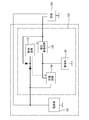
- FIG. 1 is a block diagram schematically illustrating a vehicle power supply system including a vehicle power supply control device according to a first embodiment.
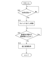
- FIG. 2 is a flowchart illustrating a control flow relating to the backup operation executed by the vehicle power supply control device according to the first embodiment.
- FIG. 3 is a block diagram schematically illustrating a vehicle power supply system including a vehicle power supply control device of a comparative example.
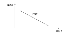
- FIG. 4 is a graph showing the relationship between the load current and the load voltage when the load required power is P.
- FIG. 5 is a graph showing the relationship between the output voltage and the load current in the prior art method.
- FIG. 6 is a graph showing the relationship between the output voltage and the load current in the method of the comparative example.
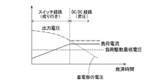
- FIG. 7 is a graph showing the relationship between the output voltage, the load current, and the voltage of the power storage unit in the method of the embodiment.
- the vehicle power supply control device of the present disclosure (1) A discharge path interposed between the power storage unit and the load-side conductive path and a switch provided in the discharge path are provided, and when the switch is in the on state, discharge occurs between the load-side conductive path and the power storage unit. Is connected between the storage circuit and the load-side conductive path and is electrically connected to the power storage section, and is electrically connected to the storage section to convert the voltage of the storage-side conductive path to convert the load-side conductive path.
- the control circuit controls the switch to be in the ON state when the output voltage of the power storage unit is less than the threshold voltage. It is desirable that the conversion circuit performs a voltage conversion operation. With this configuration, when the output voltage of the power storage unit is less than the threshold voltage, the voltage conversion circuit can perform the voltage conversion operation to output the target voltage, so that the output voltage of the power storage unit falls below the target voltage. Even in such a low case (when the remaining charge amount of the power storage unit is small), it becomes easy to drive the target load.
- the output voltage of the power storage unit is equal to or higher than the threshold voltage (when the remaining charge amount of the power storage unit is large), it is possible to prevent the output current from being forcibly increased and to reduce the required power of the load and the output voltage of the power storage unit. Since the output current can be set in accordance with the above, the current consumption can be suppressed and the target load can be efficiently driven.
- the control circuit maintains the switch in the ON state and stops the voltage conversion operation of the voltage conversion circuit while the output voltage of the power storage unit is equal to or higher than the threshold voltage after the failure state occurs, If the output voltage of the power storage unit falls below the threshold voltage while the switch is maintained in the ON state after the failure condition occurs, the voltage conversion circuit operates to perform the voltage conversion operation. Good.
- the voltage conversion circuit In the period in which the backup operation is performed, only the discharge circuit of the discharge circuit and the voltage conversion circuit is used during a relatively early period, and the required power for the load is further reduced while reducing the power consumption. Can be supplied. Further, during the relatively late period, the voltage conversion is performed using the voltage conversion circuit, so that the backup operation can be continued until the power storage unit has a lower output voltage.
- a voltage having a magnitude capable of driving the load may be continuously applied to the load-side conductive path. By doing so, it is possible to output a voltage of a magnitude capable of driving the load even during the discharging operation by the discharging circuit and the discharging operation by the voltage conversion circuit, and the voltage of a magnitude capable of driving the load can be output before and after the switching. It is possible to eliminate the period in which no output is made.
- the threshold voltage may be smaller than the target voltage.
- the target load may be a vehicle brake system.
- the power storage unit may be an electric double layer capacitor. Since the electric double layer capacitor has a characteristic that the supply voltage decreases as the amount of residual charge decreases, when the electric double layer capacitor is used for the power storage unit, the effect based on the above-described characteristics is further exerted.
- FIG. 1 discloses a vehicle system Sy that includes a vehicle power supply system 1 (hereinafter, also referred to as a power supply system 1) and a load 94 that receives power supply from the vehicle power supply system 1.
- the vehicle power supply system 1 shown in FIG. 1 includes a power supply unit 91 that functions as a main power supply, a power storage unit 92 that functions as a backup power supply, and a vehicle power supply control device 3 (hereinafter, also referred to as control device 3).
- the power supply system 1 is configured as a system capable of supplying electric power to the load 94 by the power supply system 1, and configured as a system capable of controlling the backup operation at the time of failure by the control device 3.
- the load 94 is illustrated as the power supply target, but various electric parts such as a shift-by-wire control system and an electronically controlled brake system correspond to the load 94, and the type and number thereof are not limited. ..
- the power supply unit 91 is a power supply unit mounted on a vehicle and functions as a main power supply for supplying electric power to various objects.
- the power supply unit 91 is configured, for example, as a known vehicle battery such as a lead battery.
- the power supply unit 91 has a high-potential-side terminal electrically connected to the wiring unit 81, and applies a predetermined output voltage to the wiring unit 81. In FIG. 1, fuses, ignition switches, etc. are omitted.
- the power storage unit 92 is configured by a known power storage unit such as an electric double layer capacitor (EDLC).
- the power storage unit 92 is electrically connected to the charging circuit 40, the voltage conversion circuit 30, and the discharge circuit 20 via the power storage unit side conductive path 93, and is charged by the charging circuit 40, and the voltage conversion circuit 30 or the discharge circuit. A discharge is made by 20.
- Power storage unit 92 applies an output voltage to power storage unit-side conductive path 93 according to the degree of charge.
- the power storage unit 92 functions as a backup power supply and serves as a power supply source at least when the power supply from the power supply unit 91 is interrupted.
- the power storage unit 92 and the control device 3 described later constitute the vehicle power supply device 2 (hereinafter, also referred to as the power supply device 2).
- the output voltage of the power supply unit 91 is applied to the wiring unit 81 serving as a power line when the power supply from the power supply unit 91 is normal, and various power is supplied from the power supply unit 91 via the wiring unit 81. Electric power is supplied to the electric components.
- “when the power supply from the power supply unit 91 is in a normal state that is not in a failed state” is when the output voltage of the power supply unit 91 exceeds a predetermined value, and specifically, the control circuit 10 detects The voltage of the wiring part 81 (more specifically, the voltage at the predetermined position P1 of the wiring part 81) exceeds a predetermined value.
- “when the power supply from the power supply unit 91 is in a failure state” is when the output voltage of the power supply unit 91 is equal to or lower than a predetermined value, and specifically, the wiring unit detected by the control circuit 10.
- the voltage of 81 (more specifically, the voltage of the predetermined position P1 of the wiring portion 81) is equal to or less than a predetermined value.
- the output voltage of the power supply unit 91 means the voltage between the high potential side terminal and the low potential side terminal of the power supply unit 91.
- the control device 3 includes a charging circuit 40, a voltage conversion circuit 30, a control circuit 10, and the like.
- the charging circuit 40 is a circuit that performs a charging operation for charging the power storage unit 92 based on the power supply from the power supply unit 91, is configured as a known charging circuit such as a DCDC converter, and is controlled by the control circuit 10. Make up the composition.
- the control circuit 10 controls the charging circuit 40 to supply a charging instruction signal for instructing charging of the power storage unit 92 or a charging stop signal for instructing to stop charging of the power storage unit 92.
- the control circuit 10 causes the charging circuit 40 to start the charging operation at a predetermined charging start time (for example, when the ignition switch is turned on), and the charging target in which the output voltage (charging voltage) of the power storage unit 92 is set.
- the charging instruction signal is given to the charging circuit 40 until the voltage is reached.
- the value of the charging target voltage is higher than a threshold voltage Vth described later.
- the charging circuit 40 performs a voltage conversion operation for stepping up or stepping down the power supply voltage input via the wiring section 81 when the charging instruction signal is given from the control circuit 10, and the converted voltage is stored in the power storage section 92. It is applied to the power storage unit side conductive path 93 connected to.
- the charging stop signal is given from the control circuit 10 to the charging circuit 40, the charging circuit 40 does not perform the charging operation, and at this time, the wiring section 81 and the power storage section 92 are brought into the non-conduction state.
- the voltage conversion circuit 30 is interposed between the power storage unit 92 and the load-side conductive path 95, and boosts or lowers the voltage of the power storage unit-side conductive path 93 electrically connected to the power storage unit 92 to load-side the conductive path. At least the voltage conversion operation of applying the target voltage to 95 can be performed.
- the voltage conversion circuit 30 is configured as, for example, a known step-up/down type DCDC converter of a synchronous rectification type or a diode type, and is configured to be controlled by the control circuit 10.
- the voltage conversion circuit 30 is supplied by the control circuit 10 with a discharge instruction signal instructing to discharge the power storage unit 92 or a discharge stop signal instructing to stop discharging the power storage unit 92.
- the voltage conversion circuit 30 performs a discharging operation of flowing a discharging current from the power storage unit 92 to the load 94 and a breaking operation of cutting off the discharging current according to a signal from the control circuit 10.
- the voltage conversion circuit 30 performs the step-up operation or the step-down operation using the voltage of the power storage unit side conductive path 93 to which the output voltage of the power storage unit 92 is applied as the input voltage, Discharge operation so as to apply the target voltage set to the load-side conductive path 95 on the output side (specifically, discharge operation to apply the target voltage set to the load-side conductive path 95 by the control circuit 10). )I do.
- the voltage conversion circuit 30 stops such a discharge operation and shuts off the load side conductive path 95 and the power storage unit 92 so as to be in a non-conductive state. Take action. Since the output side connected to the voltage conversion circuit 30 is connected to the load side conductive path 95 electrically connected to the load 94, the output side connected to the voltage conversion circuit 30 is discharged from the voltage conversion circuit 30 during the discharging operation. The output current (discharge current) that is output can be supplied to the load 94.
- a step-up/down type DCDC converter is illustrated as the voltage conversion circuit 30 here, the voltage conversion circuit 30 may be a DCDC converter having only a boosting function.
- the discharge circuit 20 includes a discharge path 22 interposed between the power storage unit 92 and the load-side conductive path 95, and a switch 24 provided in the discharge path 22.
- the discharge circuit 20 is a circuit in which the load-side conductive path 95 and the power storage unit 92 are electrically connected via the discharge path 22 when the switch 24 is on.
- the switch 24 may be, for example, a known semiconductor switch element such as an FET or a bipolar transistor, or a known mechanical relay.
- the power supply circuit 52 of the control circuit 10 electrically connects the diode 52A, a conductive path electrically connecting the anode of the diode 52A and the wiring portion 81, the cathode of the diode 52A and the power supply line 58 of the control circuit 10. And a conductive path for The power supply circuit 54 of the control circuit 10 electrically connects the diode 54A, a conductive path electrically connecting the anode of the diode 54A and the power storage unit side conductive path 93, and the cathode of the diode 54A to the power supply line 58. And a conductive path.
- the power supply circuit 56 of the control circuit 10 includes a diode 56A, a conductive path electrically connecting the anode of the diode 56A and the load side conductive path 95, and a conductive path electrically connecting the cathode of the diode 56A and the power supply line 58. And a road.
- the power supply circuit 54 is configured to output a voltage lower than that of the power supply circuit 52 when the power supply from the power supply unit 91 is in a normal state, and in the normal state, the power supply unit 92 supplies power via the diode 54A. The current is suppressed from flowing to the line 58 side.
- Power can be supplied to the control circuit 10 via the power supply circuit 54 from the time when the power supply from the power supply unit 91 has failed until the discharge circuit 20 outputs. After the output from the discharge circuit 20 after the failure state, when the voltage output from the power supply circuit 54 is lower than the voltage output from the power supply circuit 56, power is supplied to the control circuit 10 via the power supply circuit 56. Can be supplied.
- the control circuit 10 is a circuit that controls the charging circuit 40, the voltage conversion circuit 30, the discharging circuit 20, and the like.
- the control circuit 10 is configured as, for example, a microcomputer, and has a CPU, a memory such as a ROM or a RAM, an AD converter, and the like.
- the control circuit 10 can be supplied with power so that it can be operated by the power from the power storage unit 92 even when the power supply from the power supply unit 91 is interrupted.
- the control circuit 10 indicates, for example, that the vehicle has switched from a stopped state to a starting state (for example, a predetermined starting switch (ignition switch or other starting switch) provided on the vehicle has switched from an off state to an on state). ), the control for the backup operation shown in FIG. 2 is started.
- a starting state for example, a predetermined starting switch (ignition switch or other starting switch) provided on the vehicle has switched from an off state to an on state.
- the control circuit 10 continuously monitors whether or not the power supply from the power supply unit 91 is in a failure state (S10).
- the control circuit 10 monitors the voltage at the predetermined position P1 via a voltage signal line (not shown).
- step S10 the control circuit 10 determines whether the voltage at the predetermined position P1 (the voltage at the high-potential side terminal of the power supply unit 91) is lower than the reference voltage value V1, and the voltage value at the predetermined position P1 becomes the reference. If it does not fall below the voltage value V1, No is determined in step S10, and the determination in step S10 is performed again. That is, after starting the control of FIG. 2, the control circuit 10 repeats the determination of step S10 and the determination of No in step S10 unless the value of the voltage at the predetermined position P1 is lower than the reference voltage value V1.
- control circuit 10 determines in step S10 that the voltage value at the predetermined position P1 is lower than the reference voltage value V1, that is, when it determines that the power supply from the power supply unit 91 is in a failure state (in step S10). If determined as Yes), the switch 24 of the discharge circuit 20 is switched from the off state to the on state in step S11. Control circuit 10 performs the process of step S11 and then the process of step S12 to determine whether the voltage of power storage unit 92 is equal to or higher than threshold voltage Vth.
- the control circuit 10 monitors the value of the output voltage of the power storage unit 92 (specifically, the voltage value of the high potential side terminal) via a voltage signal line (not shown), and the value of the output voltage of the power storage unit 92 is the threshold voltage Vth. It is determined whether or not the above.
- the output voltage of power storage unit 92 means a voltage between terminals of the high potential side terminal and the low potential side terminal of power storage unit 92.
- step S12 if the value of the output voltage of power storage unit 92 is equal to or higher than threshold voltage Vth, control circuit 10 determines Yes in step S12, and performs the process of step S11 again. That is, after determining Yes in step S10, control circuit 10 continues the process of step S11 and determines Yes in step S12 unless the value of the output voltage of power storage unit 92 becomes lower than threshold voltage Vth. repeat.
- the threshold voltage Vth is, for example, a value lower than the above-described predetermined voltage value (reference voltage value V1), and is the output voltage of the power storage unit 92 when fully charged (when the power storage unit 92 is fully charged, the power storage unit side conductive path 93 It is a value lower than the value of the applied output voltage).
- the value of the output voltage (voltage between terminals) of power storage unit 92 when fully charged may be larger or smaller than the predetermined voltage value (reference voltage value V1). Further, the output voltage of power storage unit 92 at the time of full charge may be a value larger or smaller than the value of the output voltage (voltage between terminals) of power supply unit 91 at the time of full charge.
- the control circuit 10 causes the charging circuit 40 to perform a charging operation so that the output voltage (charging voltage) of the power storage unit 92 becomes equal to or higher than a predetermined reference value larger than the threshold voltage Vth (specifically, The power storage unit 92 is charged so that the value of the voltage applied to the power storage unit side conductive path 93 becomes equal to or greater than a predetermined reference value.
- a predetermined starting switch ignition switch or other starting switch
- the value of the output voltage (charging voltage) of power storage unit 92 that is, the value of the voltage applied to power storage unit side conductive path 93 is maintained at a value larger than threshold voltage Vth. It is supposed to be done.
- the control circuit 10 maintains the switch 24 in the off state from the start of the control of FIG. 2 to the start of the process of step S11. Then, from the start of the control of FIG. 2 to the start of the processing of step S13, the voltage conversion circuit 30 is maintained in the stopped state. Therefore, the control circuit 10 keeps the voltage conversion circuit 30 in the stopped state while continuing the process of step S11. As described above, the control circuit 10 outputs No after step S12 while the output voltage of the power storage unit 92 is equal to or higher than the threshold voltage Vth after the above-mentioned failure state occurs (after determining Yes in step S10). Until the determination), the switch 24 is maintained in the ON state and the voltage conversion operation of the voltage conversion circuit 30 is stopped.
- step S12 When the control circuit 10 determines in step S12 that the value of the output voltage of the power storage unit 92 is not equal to or higher than the threshold voltage Vth (No in step S12), the control circuit 10 performs the voltage conversion operation in step S13. Specifically, driving of the voltage conversion circuit 30 is started, and the voltage conversion operation is performed so that the voltage applied to the power storage unit side conductive path 93 is converted and the target voltage is applied to the load side conductive path 95.
- the value of the target voltage output by the voltage conversion circuit 30 is a value larger than the minimum drive voltage for driving the load 94, and may be a constant value larger than the threshold voltage Vth or a small constant value. Good.
- the minimum drive voltage is a lower limit value of the range of the voltage applied to the load 94 that enables the load 94 to be driven.
- the process of step S13 can be continued as long as the electric charges enough to perform the voltage conversion operation described above are accumulated.
- the control device 3 includes the discharge path 22 interposed between the power storage unit 92 and the load-side conductive path 95, and the switch 24 provided in the discharge path 22, and when the switch 24 is in the ON state.
- the discharge circuit 20 is provided so that the load-side conductive path 95 and the power storage unit 92 are electrically connected via the discharge path 22.
- control device 3 is interposed between power storage unit 92 and load-side conductive path 95, converts the voltage of power storage unit-side conductive path 93 electrically connected to power storage unit 92, and converts load-side conductive path 95.
- a voltage conversion circuit 30 capable of performing at least a voltage conversion operation of applying the target voltage.
- control device 3 includes a control circuit 10 that controls the discharge circuit 20 and the voltage conversion circuit 30. Then, when the output voltage of power storage unit 92 is equal to or higher than threshold voltage Vth in the failure state, control circuit 10 controls switch 24 to be in the ON state, and the output voltage of power storage unit 92 is less than threshold voltage Vth. If so, the voltage conversion circuit 30 is caused to perform a voltage conversion operation.
- This device can output the target voltage (output voltage) by the voltage conversion circuit 130 immediately after starting the backup operation, and outputs the target voltage (output voltage) even if the output voltage of the power storage unit 192 is lower than the load driving minimum voltage. Therefore, there is an advantage that the backup operation can be continued.
- this method even if the output voltage of the power storage unit is high, the output is suppressed to the target voltage, so that the current consumption increases accordingly. In particular, there is an undeniable decrease in efficiency when the output voltage of power storage unit 192 is higher than the target voltage (output voltage).
- the backup operation using the discharge circuit 20 can be performed during the period when the output voltage of the power storage unit 92 is high, so that the consumption current (load current) during this period is significantly increased. And the effect can be linked to the extension of the backup period or the size reduction of the power storage unit 92. Moreover, when the output voltage of power storage unit 92 becomes low, the backup operation can be continued so that the voltage is converted by voltage conversion circuit 30, and thus the backup operation can be continued for a longer time.
- control circuit 10 After the failure state occurs, control circuit 10 maintains switch 24 in the ON state and stops the voltage conversion operation of voltage conversion circuit 30 while the output voltage of power storage unit 92 is equal to or higher than threshold voltage Vth. If the output voltage of the power storage unit 92 becomes less than the threshold voltage Vth while the switch 24 is maintained in the ON state after the failure state occurs, the voltage conversion circuit 30 performs the voltage conversion operation. It works to let you. With this configuration, only the discharging circuit 20 of the discharging circuit 20 and the voltage converting circuit 30 is used for a relatively early period in the period in which the backup operation is performed, and the power consumption is further suppressed with respect to the load 94. Can supply the required power. Further, during the relatively late period, the voltage conversion circuit 30 performs the voltage conversion, so that the backup operation can be continued until the power storage unit 92 has a lower output voltage.
- Control device 3 holds the switch 24 in the ON state until the output voltage of power storage unit 92 reaches threshold voltage Vth after the failure state occurs, and after the output voltage of power storage unit 92 reaches threshold voltage Vth.
- a voltage having a magnitude capable of driving the load 94 is continuously applied to the load-side conductive path 95 during the period in which the voltage conversion operation is performed. With this configuration, it is possible to output a voltage having a magnitude capable of driving the load during the discharging operation by the discharging circuit 20 and the discharging operation by the voltage conversion circuit 30, and a magnitude capable of driving the load 94 before and after the switching. It is possible to eliminate the period in which the voltage is not output.
- the threshold voltage Vth is smaller than the target voltage output from the voltage conversion circuit 30. By doing so, the discharge by the discharge circuit 20 can be continued for a longer time.
- the target load 94 of the control device 3 may be a vehicle brake system. By doing this, it is possible to continue supplying power to the vehicle brake system that requires power supply even after a power failure, even after a power failure, and to perform such backup operation.
- the obtained configuration can be realized with a configuration that can further reduce the size and a configuration that can further continue the backup operation.
- the power storage unit 92 may be an electric double layer capacitor. Since the electric double layer capacitor has a characteristic that the supply voltage decreases as the amount of remaining charge decreases, when the electric double layer capacitor is used for the electricity storage unit 92, the effect based on the above-described characteristics is further exerted.
- the voltage conversion circuit is started from the control of FIG. 2 until the process of step S11 is started (specifically, the process of step S13 is started).
- the example of stopping 30 is shown, the present invention is not limited to this example.
- the control circuit 10 starts the voltage conversion operation of the voltage conversion circuit 30 with the start of the control of FIG. 2, and continues to output a voltage lower than that of the power supply unit 91 to the load side conductive path 95. 30 may be operated. In this case, it is preferable to stop the voltage conversion circuit 30 after starting the process of step S11.
- the lead battery is used for the power supply unit 91 as the main power supply unit, but the present invention is not limited to this configuration, and in any of the above-described embodiments or any modification of the above-described embodiments, the lead battery is used. Other known storage batteries other than the above may be used.
- the number of power supply units that configure the power supply unit 91 is not limited to one, and may include a plurality of power supply units.
- the present invention is not limited to this configuration, and the power storage unit is not limited to this configuration or in any of the modified examples described above.
- Other storage means such as a lithium-ion battery, a lithium-ion capacitor, or a nickel-hydrogen rechargeable battery may be used for 92.
- the number of power storage units that configure power storage unit 92 is not limited to one, and may be configured by a plurality of power storage units.
- the charging circuit 40 is configured as the DCDC converter has been described, but the present invention is not limited to this example in any of the above-described embodiments or any modification of the above-described embodiments, and various publicly known examples are available.
- Various charging circuits can be used.
- the number of switches in the discharge circuit is one is shown, but the number of switches may be two or more.
- the discharge circuit 20 different from the voltage conversion circuit 30 is provided, but the voltage conversion circuit 30 may function as a discharge circuit.
- the voltage conversion circuit 30 has a function of performing the voltage conversion operation described above and a function of electrically connecting the power storage unit side conductive path 93 and the load side conductive path 95 (for example, approximately the same as the voltage of the power storage unit side conductive path 93). The function of applying the voltage to the load-side conductive path 95).
Landscapes
- Engineering & Computer Science (AREA)
- Mechanical Engineering (AREA)
- Power Engineering (AREA)
- Transportation (AREA)
- Business, Economics & Management (AREA)
- Emergency Management (AREA)
- Charge And Discharge Circuits For Batteries Or The Like (AREA)
- Electric Propulsion And Braking For Vehicles (AREA)
- Regulating Braking Force (AREA)
- Stand-By Power Supply Arrangements (AREA)
Abstract
蓄電部の残電荷量が少ない場合にも対象負荷を駆動させることができ、蓄電部の残電荷量が多い場合には、効率良く対象負荷を駆動させることができる技術を実現する。 車両用電源制御装置(3)は、放電路(22)及びスイッチ(24)を備えた放電回路(20)と、電圧変換回路(30)と、放電回路(20)及び電圧変換回路(30)を制御する制御回路(10)と、を備える。制御回路(10)は、失陥状態のときに、蓄電部(92)の出力電圧が閾値電圧Vth以上である場合にはスイッチ(24)をオン状態に制御し、蓄電部(92)の出力電圧が閾値電圧Vth未満である場合には電圧変換回路(30)に電圧変換動作を行わせる。
Description
本開示は、車両用電源制御装置、及び車両用電源装置に関する。
特許文献1には、電源バックアップシステムとしての機能を有する蓄電装置を備えた車両用電源システムが開示されている。特許文献1で開示される蓄電装置は、主電源からの電力供給が失陥状態となった場合に主電源とは異なる蓄電部から電力供給を行うように動作し得るものである。
特許文献1で開示される蓄電装置は、制御回路が主電源の電圧を監視する構成となっており、制御回路は、主電源の電圧の低下を検出すると、直ちに切替スイッチをオンさせる。そして、制御回路が切替スイッチをオンさせると、蓄電部から負荷へ電力が供給される。
特許文献1で開示される蓄電装置は、いわゆる「成り行き放電」を採用しており、電源失陥に応じてなされるバックアップ動作では、蓄電部の出力電圧(端子電圧)に応じた電圧が負荷に印加される。この方法では、蓄電部から負荷への放電が継続して蓄電部の残電荷量が次第に減少すると、それに応じて負荷への供給電圧が低下することになる。そして、蓄電部の出力電圧が負荷の最低駆動電圧を下回ってしまうと、負荷を駆動できなくなる。つまり、特許文献1で開示される蓄電装置では、蓄電部の出力電圧が負荷の最低駆動電圧を下回った場合に電荷を使い切ることができなくなってしまうため、その分の電荷が無駄になってしまう。
一方で、特許文献1の蓄電装置に代えて、図3のようなバックアップ装置102を採用することも考えられる。図3で示されるバックアップ装置102は、放電回路として電圧変換回路130を用いており、電源部191の出力電圧が閾値電圧以下となったことを制御回路110が検出した場合に、電圧変換回路130から一定電圧が出力されるように、制御回路110が電圧変換回路130に電圧変換動作を行わせる。具体的には、蓄電部192の出力電圧(端子電圧)が上記一定電圧(目標電圧)を超える場合には電圧変換回路130に降圧動作を行わせ、蓄電部192の出力電圧(端子電圧)が上記一定電圧(目標電圧)を下回る場合には電圧変換回路130に昇圧動作を行わせるように、制御回路110が電圧変換回路130を制御する。この方法を用いれば、蓄電部192の出力電圧(端子電圧)が負荷194の最低駆動電圧を下回っても、昇圧動作によって最低駆動電圧以上の電圧を負荷194に与えることができるため、特許文献1の蓄電装置が抱える問題を解決しやすくなる。しかし、このバックアップ装置102のような対策だけでは、電圧変換に起因する効率の低下が懸念される。
そこで、蓄電部の残電荷量が少ない場合にも対象負荷を駆動させることができ、蓄電部の残電荷量が多い場合には、効率良く対象負荷を駆動させることができる車両用の技術を提供することを目的とする。
本開示の一つである車両用電源制御装置は、
負荷に電力を供給する電源部と、少なくとも前記電源部からの電力供給が失陥状態となった場合に負荷側導電路を介して前記負荷に電力を供給する蓄電部と、を備えた車両用電源システムを制御する車両用電源制御装置であって、
前記蓄電部と前記負荷側導電路との間に介在する放電路と、前記放電路に設けられるスイッチと、を備え、前記スイッチがオン状態のときに前記負荷側導電路と前記蓄電部との間が前記放電路を介して導通した状態となる放電回路と、
前記蓄電部と前記負荷側導電路との間に介在し、前記蓄電部に電気的に接続された蓄電部側導電路の電圧を変換して前記負荷側導電路に目標電圧を印加する電圧変換動作を少なくとも行い得る電圧変換回路と、
前記放電回路及び前記電圧変換回路を制御する制御回路と、
を備え、
前記制御回路は、前記失陥状態のときに、前記蓄電部の出力電圧が閾値電圧以上である場合には前記スイッチを前記オン状態に制御し、前記蓄電部の出力電圧が前記閾値電圧未満である場合には前記電圧変換回路に前記電圧変換動作を行わせる。
負荷に電力を供給する電源部と、少なくとも前記電源部からの電力供給が失陥状態となった場合に負荷側導電路を介して前記負荷に電力を供給する蓄電部と、を備えた車両用電源システムを制御する車両用電源制御装置であって、
前記蓄電部と前記負荷側導電路との間に介在する放電路と、前記放電路に設けられるスイッチと、を備え、前記スイッチがオン状態のときに前記負荷側導電路と前記蓄電部との間が前記放電路を介して導通した状態となる放電回路と、
前記蓄電部と前記負荷側導電路との間に介在し、前記蓄電部に電気的に接続された蓄電部側導電路の電圧を変換して前記負荷側導電路に目標電圧を印加する電圧変換動作を少なくとも行い得る電圧変換回路と、
前記放電回路及び前記電圧変換回路を制御する制御回路と、
を備え、
前記制御回路は、前記失陥状態のときに、前記蓄電部の出力電圧が閾値電圧以上である場合には前記スイッチを前記オン状態に制御し、前記蓄電部の出力電圧が前記閾値電圧未満である場合には前記電圧変換回路に前記電圧変換動作を行わせる。
本開示の一つである車両用電源装置は、
上記車両用電源制御装置と、
上記蓄電部と、
を含む。
上記車両用電源制御装置と、
上記蓄電部と、
を含む。
本開示によれば、蓄電部の残電荷量が少ない場合にも対象負荷を駆動させることができ、蓄電部の残電荷量が多い場合には、効率良く対象負荷を駆動させることができる。
[本開示の実施形態の説明]
最初に本開示の実施態様を列記して説明する。
本開示の車両用電源制御装置は、
(1)蓄電部と負荷側導電路との間に介在する放電路と、放電路に設けられるスイッチと、を備え、スイッチがオン状態のときに負荷側導電路と蓄電部との間が放電路を介して導通した状態となる放電回路と、蓄電部と負荷側導電路との間に介在し、蓄電部に電気的に接続された蓄電部側導電路の電圧を変換して負荷側導電路に目標電圧を印加する電圧変換動作を少なくとも行い得る電圧変換回路と、放電回路及び電圧変換回路を制御する制御回路と、を備えたものとすることが望ましい。そして、制御回路は、失陥状態のときに、蓄電部の出力電圧が閾値電圧以上である場合にはスイッチをオン状態に制御し、蓄電部の出力電圧が閾値電圧未満である場合には電圧変換回路に電圧変換動作を行わせる構成であることが望ましい。
このようにすれば、蓄電部の出力電圧が閾値電圧未満である場合に電圧変換回路に電圧変換動作を行わせて目標電圧を出力させることができるため、蓄電部の出力電圧が目標電圧を下回るような低い場合(蓄電部の残電荷量が少ない場合)にも対象負荷を駆動させやすくなる。一方、蓄電部の出力電圧が閾値電圧以上である場合(蓄電部の残電荷量が多い場合)には、強制的に出力電流を増大させることを抑え、負荷の必要電力と蓄電部の出力電圧とに応じた出力電流とすることができるため、消費電流を抑え、効率良く対象負荷を駆動させることができる。
最初に本開示の実施態様を列記して説明する。
本開示の車両用電源制御装置は、
(1)蓄電部と負荷側導電路との間に介在する放電路と、放電路に設けられるスイッチと、を備え、スイッチがオン状態のときに負荷側導電路と蓄電部との間が放電路を介して導通した状態となる放電回路と、蓄電部と負荷側導電路との間に介在し、蓄電部に電気的に接続された蓄電部側導電路の電圧を変換して負荷側導電路に目標電圧を印加する電圧変換動作を少なくとも行い得る電圧変換回路と、放電回路及び電圧変換回路を制御する制御回路と、を備えたものとすることが望ましい。そして、制御回路は、失陥状態のときに、蓄電部の出力電圧が閾値電圧以上である場合にはスイッチをオン状態に制御し、蓄電部の出力電圧が閾値電圧未満である場合には電圧変換回路に電圧変換動作を行わせる構成であることが望ましい。
このようにすれば、蓄電部の出力電圧が閾値電圧未満である場合に電圧変換回路に電圧変換動作を行わせて目標電圧を出力させることができるため、蓄電部の出力電圧が目標電圧を下回るような低い場合(蓄電部の残電荷量が少ない場合)にも対象負荷を駆動させやすくなる。一方、蓄電部の出力電圧が閾値電圧以上である場合(蓄電部の残電荷量が多い場合)には、強制的に出力電流を増大させることを抑え、負荷の必要電力と蓄電部の出力電圧とに応じた出力電流とすることができるため、消費電流を抑え、効率良く対象負荷を駆動させることができる。
(2)制御回路は、失陥状態が発生した後、蓄電部の出力電圧が閾値電圧以上となっている間は、スイッチをオン状態で維持するとともに電圧変換回路の電圧変換動作を停止させ、失陥状態が発生した後、スイッチをオン状態で維持しているときに蓄電部の出力電圧が閾値電圧未満になった場合には、電圧変換回路に電圧変換動作を行わせるように動作してもよい。
このようにすれば、バックアップ動作を行う期間において、相対的に早い期間は、放電回路及び電圧変換回路のうちの放電回路のみを用い、より消費電力を抑えた形で負荷に対して必要電力を供給することができる。また、相対的に遅い期間は、電圧変換回路を用いて電圧変換を行うことで、蓄電部がより低い出力電圧となるときまでバックアップ動作を継続することができる。
このようにすれば、バックアップ動作を行う期間において、相対的に早い期間は、放電回路及び電圧変換回路のうちの放電回路のみを用い、より消費電力を抑えた形で負荷に対して必要電力を供給することができる。また、相対的に遅い期間は、電圧変換回路を用いて電圧変換を行うことで、蓄電部がより低い出力電圧となるときまでバックアップ動作を継続することができる。
(3)失陥状態が発生した後、蓄電部の出力電圧が閾値電圧となるまでスイッチをオン状態で維持する期間と蓄電部の出力電圧が閾値電圧となった後に電圧変換動作を行わせる期間とで継続して負荷を駆動可能な大きさの電圧を負荷側導電路に印加するものであってもよい。このようにすれば、放電回路による放電動作中でも電圧変換回路による放電動作中でも負荷を駆動可能な大きさの電圧を出力することができ、その切り替えの前後でも負荷を駆動可能な大きさの電圧が出力されない期間を無くすことができる。
(4)閾値電圧は、目標電圧よりも小さくてもよい。このようにすれば、放電回路による放電をより長く継続することができるため、消費電流を抑制する効果が一層高まる。
(5)対象となる負荷が、車両用ブレーキシステムであってもよい。このようにすれば、電源失陥時であっても電力供給が望まれる車両用ブレーキシステムに対し、失陥状態の後にも電力供給を継続することができ、しかも、このようなバックアップ動作を行い得る構成を、よりサイズを抑え得る構成で且つよりバックアップ動作を継続し得る構成で実現することができる。
(6)蓄電部は、電気二重層キャパシタであってもよい。
電気二重層キャパシタは、残電荷量の減少に伴って供給電圧が低下する特性を有するため、蓄電部に電気二重層キャパシタを採用した場合、上述の特徴に基づく効果がより一層発揮される。
電気二重層キャパシタは、残電荷量の減少に伴って供給電圧が低下する特性を有するため、蓄電部に電気二重層キャパシタを採用した場合、上述の特徴に基づく効果がより一層発揮される。
[本開示の実施形態の詳細]
本開示の実装部品の取付け構造の具体例を、以下に図面を参照しつつ説明する。なお、本発明はこの例示に限定されるものではなく、特許請求の範囲によって示され、特許請求の範囲と均等の意味および範囲内でのすべての変更が含まれることが意図される。
本開示の実装部品の取付け構造の具体例を、以下に図面を参照しつつ説明する。なお、本発明はこの例示に限定されるものではなく、特許請求の範囲によって示され、特許請求の範囲と均等の意味および範囲内でのすべての変更が含まれることが意図される。
<実施例1>
図1には、車両用電源システム1(以下、電源システム1ともいう)と、車両用電源システム1から電力供給を受ける負荷94とを備えた車両システムSyが開示されている。図1で示される車両用電源システム1は、主電源として機能する電源部91と、バックアップ電源として機能する蓄電部92と、車両用電源制御装置3(以下、制御装置3ともいう)とを備える。電源システム1は、電源システム1によって負荷94に電力を供給し得るシステムとして構成され、且つ、制御装置3によって失陥時のバックアップ動作を制御し得るシステムとして構成されている。なお、図1では、電力供給対象として負荷94を例示しているが、負荷94としては、シフトバイワイヤ制御システム、電子制御ブレーキシステムなど、様々な電気部品が該当し、その種類や数は限定されない。
図1には、車両用電源システム1(以下、電源システム1ともいう)と、車両用電源システム1から電力供給を受ける負荷94とを備えた車両システムSyが開示されている。図1で示される車両用電源システム1は、主電源として機能する電源部91と、バックアップ電源として機能する蓄電部92と、車両用電源制御装置3(以下、制御装置3ともいう)とを備える。電源システム1は、電源システム1によって負荷94に電力を供給し得るシステムとして構成され、且つ、制御装置3によって失陥時のバックアップ動作を制御し得るシステムとして構成されている。なお、図1では、電力供給対象として負荷94を例示しているが、負荷94としては、シフトバイワイヤ制御システム、電子制御ブレーキシステムなど、様々な電気部品が該当し、その種類や数は限定されない。
電源部91は、車両に搭載される電源部であり且つ様々な対象へ電力を供給するための主電源として機能する。電源部91は、例えば、鉛バッテリ等の公知の車載バッテリとして構成されている。電源部91は、高電位側の端子が配線部81に電気的に接続され、配線部81に対して所定の出力電圧を印加する。なお、図1では、ヒューズやイグニッションスイッチなどは省略して示している。
蓄電部92は、例えば、電気二重層キャパシタ(EDLC)等の公知の蓄電手段によって構成されている。蓄電部92は蓄電部側導電路93を介して充電回路40、電圧変換回路30、及び放電回路20に電気的に接続されており、充電回路40によって充電がなされ、電圧変換回路30又は放電回路20によって放電がなされる。蓄電部92は、蓄電部側導電路93に対して充電度合いに応じた出力電圧を印加する。この蓄電部92は、バックアップ電源として機能し、少なくとも電源部91からの電力供給が途絶えたときに電力供給源となる。本構成では、蓄電部92と後述する制御装置3とによって車両用電源装置2(以下、電源装置2ともいう)が構成されている。
電源システム1は、電源部91からの電力供給が低下していない正常のときに電源部91の出力電圧が電力線となる配線部81に印加され、電源部91から配線部81を介して様々な電気部品に電力が供給される。本構成において「電源部91からの電力供給が失陥状態ではない正常状態のとき」とは、電源部91の出力電圧が所定値を超えるときであり、具体的には、制御回路10が検出する配線部81の電圧(より詳しくは、配線部81の所定位置P1の電圧)が所定値を超えるときである。逆に、「電源部91からの電力供給が失陥状態であるとき」とは、電源部91の出力電圧が所定値以下のときであり、具体的には、制御回路10が検出する配線部81の電圧(より詳しくは、配線部81の所定位置P1の電圧)が所定値以下のときである。なお、電源部91の出力電圧は、電源部91の高電位側端子と低電位側端子との端子間電圧を意味する。
制御装置3は、充電回路40、電圧変換回路30、制御回路10などを備える。
充電回路40は、電源部91からの電力供給に基づいて蓄電部92を充電する充電動作を行う回路であり、例えば、DCDCコンバータ等の公知の充電回路として構成され、制御回路10によって制御される構成をなす。制御回路10は、充電回路40に対し、蓄電部92の充電を指示する充電指示信号、又は蓄電部92の充電停止を指示する充電停止信号を与えるように充電制御を行う。制御回路10は、例えば所定の充電開始時(例えばイグニッションスイッチがオン状態になった時)に充電回路40に充電動作を開始させ、蓄電部92の出力電圧(充電電圧)が設定された充電目標電圧に達するまで充電回路40に対して充電指示信号を与える。なお、充電目標電圧の値は、後述する閾値電圧Vthよりも高い値である。充電回路40は、制御回路10から充電指示信号が与えられているときに、配線部81を介して入力される電源電圧を昇圧又は降圧する電圧変換動作を行い、その変換した電圧を蓄電部92に接続された蓄電部側導電路93に印加する。制御回路10から充電回路40に対して充電停止信号が与えられているときには、充電回路40は充電動作を行わず、このときには、配線部81と蓄電部92とを非導通状態とする。
電圧変換回路30は、蓄電部92と負荷側導電路95との間に介在し、蓄電部92に電気的に接続された蓄電部側導電路93の電圧を昇圧又は降圧して負荷側導電路95に目標電圧を印加する電圧変換動作を少なくとも行い得る。電圧変換回路30は、例えば同期整流方式又はダイオード方式の公知の昇降圧型DCDCコンバータとして構成され、制御回路10によって制御される構成をなす。電圧変換回路30には、制御回路10によって、蓄電部92の放電を指示する放電指示信号、又は蓄電部92の放電停止を指示する放電停止信号が与えられる。電圧変換回路30は、制御回路10からの信号に応じて、蓄電部92から負荷94に放電電流を流す放電動作と、放電電流を遮断する遮断動作とを行う。電圧変換回路30は、制御回路10から放電指示信号が与えられている場合、蓄電部92の出力電圧が印加される蓄電部側導電路93の電圧を入力電圧として昇圧動作又は降圧動作を行い、出力側の負荷側導電路95に対して設定された目標電圧を印加するように放電動作(具体的には、負荷側導電路95に対し制御回路10で設定された目標電圧を印加する放電動作)を行う。電圧変換回路30は、制御回路10から放電停止信号が与えられている場合、このような放電動作を停止させ、負荷側導電路95と蓄電部92との間を非導通状態とするように遮断動作を行う。電圧変換回路30に接続された出力側は、負荷94に電気的に接続された負荷側導電路95に接続されているため、電圧変換回路30が放電動作を行っているときには電圧変換回路30から出力される出力電流(放電電流)が負荷94に供給されうる。なお、ここでは電圧変換回路30として昇降圧型のDCDCコンバータを例示したが、電圧変換回路30は、昇圧機能のみを備えたDCDCコンバータであってもよい。
放電回路20は、蓄電部92と負荷側導電路95との間に介在する放電路22と、放電路22に設けられるスイッチ24と、を備える。放電回路20は、スイッチ24がオン状態のときに負荷側導電路95と蓄電部92との間が放電路22を介して導通した状態となる回路である。スイッチ24は、例えば、FETやバイポーラトランジスタなどの公知の半導体スイッチ素子であってもよく、公知の機械式リレーであってもよい。
制御回路10の電源回路52は、ダイオード52Aと、ダイオード52Aのアノードと配線部81とを電気的に接続する導電路と、ダイオード52Aのカソードと制御回路10の電源線58とを電気的に接続する導電路とを備える。制御回路10の電源回路54は、ダイオード54Aと、ダイオード54Aのアノードと蓄電部側導電路93とを電気的に接続する導電路と、ダイオード54Aのカソードと電源線58とを電気的に接続する導電路とを備える。制御回路10の電源回路56は、ダイオード56Aと、ダイオード56Aのアノードと負荷側導電路95とを電気的に接続する導電路と、ダイオード56Aのカソードと電源線58とを電気的に接続する導電路とを備える。なお、電源回路54は、電源部91からの電力供給が正常状態のときに電源回路52よりも低い電圧を出力するように構成され、正常状態のときには蓄電部92側からダイオード54Aを介して電源線58側へ電流が流れることが抑制される。電源部91からの電力供給が失陥状態となってから放電回路20が出力を行うまでは電源回路54を介して制御回路10に電力を供給し得る。失陥状態になった後に放電回路20から出力がなされた後には、電源回路54による電圧の出力が電源回路56による電圧の出力を下回った場合に電源回路56を介して制御回路10に電力を供給し得る。
制御回路10は、充電回路40、電圧変換回路30、放電回路20などを制御する回路である。制御回路10は、例えばマイクロコンピュータとして構成されており、CPU、ROM又はRAM等のメモリ、AD変換器等を有している。制御回路10は、電源部91からの電力供給が途絶えた場合でも、蓄電部92からの電力によって動作することが可能となるように電力供給を受け得る。
次に、バックアップ動作に関する制御を説明する。
制御回路10は、例えば、車両が停止状態から始動状態に切り替わったこと(例えば、車両に設けられた所定の始動スイッチ(イグニッションスイッチ、又はその他の始動スイッチ)がオフ状態からオン状態に切り替わったこと)を条件として、図2で示すバックアップ動作用の制御を開始する。
制御回路10は、例えば、車両が停止状態から始動状態に切り替わったこと(例えば、車両に設けられた所定の始動スイッチ(イグニッションスイッチ、又はその他の始動スイッチ)がオフ状態からオン状態に切り替わったこと)を条件として、図2で示すバックアップ動作用の制御を開始する。
制御回路10は、図2の制御を開始した後、電源部91からの電力供給が失陥状態であるか否かを継続的に監視する(S10)。制御回路10は、図示しない電圧信号線を介して所定位置P1の電圧を監視している。制御回路10は、ステップS10では、所定位置P1の電圧(電源部91の高電位側の端子の電圧)が基準電圧値V1を下回るか否かを判定し、所定位置P1の電圧の値が基準電圧値V1を下回らない場合には、ステップS10でNoと判定し、再びステップS10の判定を行う。つまり、制御回路10は、図2の制御を開始した後、所定位置P1の電圧の値が基準電圧値V1を下回らない限り、ステップS10の判定を繰り返し、ステップS10でNoとする判定を繰り返す。
制御回路10は、ステップS10において所定位置P1の電圧の値が基準電圧値V1を下回ると判定した場合、即ち、電源部91からの電力供給が失陥状態であると判定した場合(ステップS10でYesと判定した場合)、ステップS11にて、放電回路20のスイッチ24をオフ状態からオン状態に切り替える。制御回路10は、ステップS11の処理を行った後、ステップS12の処理を行い、蓄電部92の電圧が閾値電圧Vth以上であるか否かを判定する。制御回路10は、図示しない電圧信号線を介して蓄電部92の出力電圧の値(具体的には高電位側端子の電圧値)を監視し、蓄電部92の出力電圧の値が閾値電圧Vth以上であるか否かを判定する。なお、蓄電部92の出力電圧は、蓄電部92の高電位側端子と低電位側端子との端子間電圧を意味する。
制御回路10は、ステップS12では、蓄電部92の出力電圧の値が閾値電圧Vth以上であれば、ステップS12でYesと判定し、ステップS11の処理を再び行う。つまり、制御回路10は、ステップS10でYesと判定した後には、蓄電部92の出力電圧の値が閾値電圧Vth未満とならない限り、ステップS11の処理を継続させ、ステップS12でYesとする判定を繰り返す。閾値電圧Vthは、例えば、上述の所定電圧値(基準電圧値V1)よりも低い値であり、満充電時の蓄電部92の出力電圧(蓄電部92が満充電時に蓄電部側導電路93に印加される出力電圧の値)よりも低い値である。また、満充電時の蓄電部92の出力電圧(端子間電圧)の値は、上記所定電圧値(基準電圧値V1)よりも大きい値であってもよく、小さい値であってもよい。また、満充電時の蓄電部92の出力電圧は、満充電時の電源部91の出力電圧(端子間電圧)の値よりも大きい値であってもよく、小さい値であってもよい。
なお、本構成では、例えば、車両が停止状態から始動状態に切り替わったこと(例えば、車両に設けられた所定の始動スイッチ(イグニッションスイッチ、又はその他の始動スイッチ)がオフ状態からオン状態に切り替わったこと)を条件として、制御回路10が充電回路40に充電動作を行わせ、蓄電部92の出力電圧(充電電圧)が閾値電圧Vthよりも大きい所定基準値以上となるように(具体的には、蓄電部側導電路93に印加される電圧の値が所定基準値以上となるように)、蓄電部92の充電がなされるようになっている。従って、このような充電が完了した後には、蓄電部92の出力電圧(充電電圧)の値、即ち、蓄電部側導電路93に印加される電圧の値は閾値電圧Vthよりも大きい値で維持されるようになっている。
また、本構成では、制御回路10は、図2の制御を開始してからステップS11の処理を開始するまでの間は、スイッチ24をオフ状態で維持する。そして、図2の制御を開始してからステップS13の処理を開始するまでは、電圧変換回路30を停止状態で維持する。従って、制御回路10は、ステップS11の処理を継続させている間、電圧変換回路30を停止状態とする。このように、制御回路10は、上述の失陥状態が発生した後、蓄電部92の出力電圧が閾値電圧Vth以上となっている間(ステップS10でYesと判定した後、ステップS12でNoと判定するまでの間)は、スイッチ24をオン状態で維持するとともに電圧変換回路30の電圧変換動作を停止させた状態とする。
制御回路10は、ステップS12において蓄電部92の出力電圧の値が閾値電圧Vth以上でないと判定した場合(ステップS12でNoと判定した場合)、ステップS13にて電圧変換動作を行う。具体的には、電圧変換回路30の駆動を開始させ、蓄電部側導電路93に印加された電圧を変換して負荷側導電路95に目標電圧を印加するように電圧変換動作を行わせる。電圧変換回路30が出力する目標電圧の値は、負荷94を駆動するための最低駆動電圧よりも大きい値であり、閾値電圧Vthよりも大きい一定値であってもよく、小さい一定値であってもよい。最低駆動電圧とは、負荷94に印加する電圧の範囲のうち負荷94が駆動可能となる下限の値である。このステップS13の処理は、上述の電圧変換動作が可能な程度の電荷が蓄積されている限り、継続することができる。
ここで、本開示の効果を例示する。
本開示に係る制御装置3は、蓄電部92と負荷側導電路95との間に介在する放電路22と、放電路22に設けられるスイッチ24と、を備え、スイッチ24がオン状態のときに負荷側導電路95と蓄電部92との間が放電路22を介して導通した状態となる放電回路20を備える。更に、制御装置3は、蓄電部92と負荷側導電路95との間に介在し、蓄電部92に電気的に接続された蓄電部側導電路93の電圧を変換して負荷側導電路95に目標電圧を印加する電圧変換動作を少なくとも行い得る電圧変換回路30を備える。更に、制御装置3は、放電回路20及び電圧変換回路30を制御する制御回路10を備える。そして、制御回路10は、失陥状態のときに、蓄電部92の出力電圧が閾値電圧Vth以上である場合にはスイッチ24をオン状態に制御し、蓄電部92の出力電圧が閾値電圧Vth未満である場合には電圧変換回路30に電圧変換動作を行わせる。
本開示に係る制御装置3は、蓄電部92と負荷側導電路95との間に介在する放電路22と、放電路22に設けられるスイッチ24と、を備え、スイッチ24がオン状態のときに負荷側導電路95と蓄電部92との間が放電路22を介して導通した状態となる放電回路20を備える。更に、制御装置3は、蓄電部92と負荷側導電路95との間に介在し、蓄電部92に電気的に接続された蓄電部側導電路93の電圧を変換して負荷側導電路95に目標電圧を印加する電圧変換動作を少なくとも行い得る電圧変換回路30を備える。更に、制御装置3は、放電回路20及び電圧変換回路30を制御する制御回路10を備える。そして、制御回路10は、失陥状態のときに、蓄電部92の出力電圧が閾値電圧Vth以上である場合にはスイッチ24をオン状態に制御し、蓄電部92の出力電圧が閾値電圧Vth未満である場合には電圧変換回路30に電圧変換動作を行わせる。
このようにすれば、蓄電部92の出力電圧が閾値電圧未満である場合に電圧変換回路30に電圧変換動作を行わせて目標電圧を出力させることができるため、蓄電部92の出力電圧が目標電圧を下回るような低い場合(蓄電部92の残電荷量が少ない場合)にも対象負荷94を駆動させやすくなる。一方、蓄電部92の出力電圧が閾値電圧Vth以上である場合(蓄電部92の残電荷量が多い場合)には、強制的に出力電流を増大させることを抑え、負荷94の必要電力と蓄電部92の出力電圧とに応じた出力電流とすることができるため、消費電流を抑え、効率良く対象負荷94を駆動させることができる。
ここで、本構成の効果を更に詳しく説明する。
例えば、負荷94に必要な電力がPである場合、電力Pを生じさせるために必要となる電流と電圧との関係は図4のようになる。つまり、印加する電圧が大きければ必要となる電流は少なくて済み、印加する電圧が小さくなるほど電流が大きくなる。この点を踏まえ、特許文献1で行われるような成り行き放電を考えてみると、この方法では、図5のようにバックアップ動作開始直後からのある程度の期間は、蓄電部から高い出力電圧でバックアップ動作を行うことができるため、消費電流を抑えやすいという特徴がある。しかし、この方法では、蓄電部の出力電圧が負荷駆動最低電圧を下回るとバックアップ動作が行えなくなるため、それ以降の期間は、蓄電部に蓄積された電荷が無駄になってしまう。
例えば、負荷94に必要な電力がPである場合、電力Pを生じさせるために必要となる電流と電圧との関係は図4のようになる。つまり、印加する電圧が大きければ必要となる電流は少なくて済み、印加する電圧が小さくなるほど電流が大きくなる。この点を踏まえ、特許文献1で行われるような成り行き放電を考えてみると、この方法では、図5のようにバックアップ動作開始直後からのある程度の期間は、蓄電部から高い出力電圧でバックアップ動作を行うことができるため、消費電流を抑えやすいという特徴がある。しかし、この方法では、蓄電部の出力電圧が負荷駆動最低電圧を下回るとバックアップ動作が行えなくなるため、それ以降の期間は、蓄電部に蓄積された電荷が無駄になってしまう。
一方、図3のような装置では、図6のような変化となる。この装置は、バックアップ動作開始直後から電圧変換回路130によって目標電圧(出力電圧)を出力することができ、蓄電部192の出力電圧が負荷駆動最低電圧を下回っても目標電圧(出力電圧)の出力を継続することができるため、バックアップ動作を継続し得るというメリットがある。しかし、この方法では、蓄電部の出力電圧が高い場合でも、目標電圧に抑えて出力するため、その分、消費電流が大きくなってしまう。特に、蓄電部192の出力電圧が目標電圧(出力電圧)よりも大きい期間での効率の低下は否めない。
しかし、上述した本構成では、図7のように、蓄電部92の出力電圧が大きい期間は放電回路20を用いたバックアップ動作を行うことができるため、この期間の消費電流(負荷電流)を格段に抑えることができ、この効果をバックアップ期間の延長又は蓄電部92のサイズ低減に結び付けることができる。しかも、蓄電部92の出力電圧が低くなった場合には、電圧変換回路30によって昇圧するようにバックアップ動作を継続することができるため、より長くバックアップ動作を継続することができる。
制御回路10は、失陥状態が発生した後、蓄電部92の出力電圧が閾値電圧Vth以上となっている間は、スイッチ24をオン状態で維持するとともに電圧変換回路30の電圧変換動作を停止させ、失陥状態が発生した後、スイッチ24をオン状態で維持しているときに蓄電部92の出力電圧が閾値電圧Vth未満になった場合には、電圧変換回路30に電圧変換動作を行わせるように動作する。このようにすれば、バックアップ動作を行う期間において、相対的に早い期間は、放電回路20及び電圧変換回路30のうちの放電回路20のみを用い、より消費電力を抑えた形で負荷94に対して必要電力を供給することができる。また、相対的に遅い期間は、電圧変換回路30を用いて電圧変換を行うことで、蓄電部92がより低い出力電圧となるときまでバックアップ動作を継続することができる。
制御装置3は、失陥状態が発生した後、蓄電部92の出力電圧が閾値電圧Vthとなるまでスイッチ24をオン状態で維持する期間と蓄電部92の出力電圧が閾値電圧Vthとなった後に電圧変換動作を行わせる期間とで継続して負荷94を駆動可能な大きさの電圧を負荷側導電路95に印加する。このようにすれば、放電回路20による放電動作中でも電圧変換回路30による放電動作中でも負荷を駆動可能な大きさの電圧を出力することができ、その切り替えの前後でも負荷94を駆動可能な大きさの電圧が出力されない期間を無くすことができる。
制御装置3において、閾値電圧Vthは、電圧変換回路30で出力される目標電圧よりも小さい。このようにすれば、放電回路20による放電をより長く継続することができる。
制御装置3は、対象となる負荷94が車両用ブレーキシステムであってもよい。このようにすれば、電源失陥時であっても電力供給が望まれる車両用ブレーキシステムに対し、失陥状態の後にも電力供給を継続することができ、しかも、このようなバックアップ動作を行い得る構成を、よりサイズを抑え得る構成で且つよりバックアップ動作を継続し得る構成で実現することができる。
蓄電部92は、電気二重層キャパシタであってもよい。電気二重層キャパシタは、残電荷量の減少に伴って供給電圧が低下する特性を有するため、蓄電部92に電気二重層キャパシタを採用した場合、上述の特徴に基づく効果がより一層発揮される。
[本開示の他の実施形態]
今回開示された実施の形態はすべての点で例示であって制限的なものではないと考えるべきである。例えば、以下の実施形態を採用することができる。
今回開示された実施の形態はすべての点で例示であって制限的なものではないと考えるべきである。例えば、以下の実施形態を採用することができる。
上述した実施例では、図2の制御を行う場合に、図2の制御を開始してからステップS11の処理を開始するまで(具体的には、ステップS13の処理を開始するまで)電圧変換回路30を停止させる例を示したが、この例に限定されない。例えば、制御回路10は、図2の制御の開始に伴って電圧変換回路30の電圧変換動作を開始させ、電源部91よりも低い電圧を負荷側導電路95に出力し続けるように電圧変換回路30を動作させてもよい。この場合、ステップS11の処理を開始した後に電圧変換回路30を停止させるとよい。
上述した実施例では、主電源部としての電源部91に鉛バッテリを用いているが、この構成に限定されず、上述した実施例又は上述した実施例を変更したいずれの例においても、鉛バッテリ以外の公知の他の蓄電池を用いてもよい。電源部91を構成する電源手段の数は1つに限定されず、複数の電源手段によって構成されていてもよい。
上述した実施例では、蓄電部92に電気二重層キャパシタ(EDLC)を用いているが、この構成に限定されず、上述した実施例又は上述した実施例を変更したいずれの例においても、蓄電部92にリチウムイオン電池、リチウムイオンキャパシタ、ニッケル水素充電池などの他の蓄電手段を用いてもよい。また、蓄電部92を構成する蓄電手段の数は1つに限定されず、複数の蓄電手段によって構成されていてもよい。
上述した実施例では、充電回路40がDCDCコンバータとして構成される例を説明したが、上述した実施例又は上述した実施例を変更したいずれの例においても、この例に限定されず、公知の様々な充電回路を用いることができる。
上述した実施例では、放電回路のスイッチが1つである例を示したが、2以上であってもよい。
上述した実施例では、電圧変換回路30とは別の放電回路20を設けたが、電圧変換回路30が放電回路としての機能を果たしてもよい。この場合、電圧変換回路30が、上述の電圧変換動作を行う機能と、蓄電部側導電路93と負荷側導電路95とを導通させる機能(例えば、蓄電部側導電路93の電圧と同程度の電圧を負荷側導電路95に印加する機能)とを実現できればよい。
1…車両用電源システム
2…車両用電源装置
3…車両用電源制御装置
10,110…制御回路
20…放電回路
22…放電路
24…スイッチ
30,130…電圧変換回路
40…充電回路
52,54,56…電源回路
52A,54A,56A…ダイオード
58…電源線
81…配線部
91,191…電源部
92,192…蓄電部
93…蓄電部側導電路
94,194…負荷
95…負荷側導電路
102…バックアップ装置
Sy…車両システム
2…車両用電源装置
3…車両用電源制御装置
10,110…制御回路
20…放電回路
22…放電路
24…スイッチ
30,130…電圧変換回路
40…充電回路
52,54,56…電源回路
52A,54A,56A…ダイオード
58…電源線
81…配線部
91,191…電源部
92,192…蓄電部
93…蓄電部側導電路
94,194…負荷
95…負荷側導電路
102…バックアップ装置
Sy…車両システム
Claims (7)
- 負荷に電力を供給する電源部と、少なくとも前記電源部からの電力供給が失陥状態となった場合に負荷側導電路を介して前記負荷に電力を供給する蓄電部と、を備えた車両用電源システムを制御する車両用電源制御装置であって、
前記蓄電部と前記負荷側導電路との間に介在する放電路と、前記放電路に設けられるスイッチと、を備え、前記スイッチがオン状態のときに前記負荷側導電路と前記蓄電部との間が前記放電路を介して導通した状態となる放電回路と、
前記蓄電部と前記負荷側導電路との間に介在し、前記蓄電部に電気的に接続された蓄電部側導電路の電圧を変換して前記負荷側導電路に目標電圧を印加する電圧変換動作を少なくとも行い得る電圧変換回路と、
前記放電回路及び前記電圧変換回路を制御する制御回路と、
を備え、
前記制御回路は、前記失陥状態のときに、前記蓄電部の出力電圧が閾値電圧以上である場合には前記スイッチを前記オン状態に制御し、前記蓄電部の出力電圧が前記閾値電圧未満である場合には前記電圧変換回路に前記電圧変換動作を行わせる
車両用電源制御装置。 - 前記制御回路は、
前記失陥状態が発生した後、前記蓄電部の出力電圧が前記閾値電圧以上となっている間は、前記スイッチを前記オン状態で維持するとともに前記電圧変換回路の前記電圧変換動作を停止させ、
前記失陥状態が発生した後、前記スイッチを前記オン状態で維持しているときに前記蓄電部の出力電圧が前記閾値電圧未満になった場合には、前記電圧変換回路に前記電圧変換動作を行わせる
請求項1に記載の車両用電源制御装置。 - 前記失陥状態が発生した後、前記蓄電部の出力電圧が前記閾値電圧となるまで前記スイッチを前記オン状態で維持する期間と前記蓄電部の出力電圧が前記閾値電圧となった後に前記電圧変換動作を行わせる期間とで継続して前記負荷を駆動可能な大きさの電圧を前記負荷側導電路に印加する
請求項1又は請求項2に記載の車両用電源制御装置。 - 前記閾値電圧は、前記目標電圧よりも小さい請求項1から請求項3のいずれか一項に記載の車両用電源制御装置。
- 前記負荷は、車両用ブレーキシステムである
請求項1から請求項4のいずれか一項に記載の車両用電源制御装置。 - 前記蓄電部は、電気二重層キャパシタである請求項1から請求項5のいずれか一項に記載の車両用電源制御装置。
- 請求項1から請求項6のいずれか一項に記載の車両用電源制御装置と、
前記蓄電部と、
を含む車両用電源装置。
Priority Applications (2)
| Application Number | Priority Date | Filing Date | Title |
|---|---|---|---|
| CN202080009852.0A CN113316526B (zh) | 2019-01-22 | 2020-01-07 | 车辆用电源控制装置及车辆用电源装置 |
| US17/423,978 US20220089111A1 (en) | 2019-01-22 | 2020-01-07 | Vehicle power control apparatus and vehicle power apparatus |
Applications Claiming Priority (2)
| Application Number | Priority Date | Filing Date | Title |
|---|---|---|---|
| JP2019008416A JP7120041B2 (ja) | 2019-01-22 | 2019-01-22 | 車両用電源制御装置、及び車両用電源装置 |
| JP2019-008416 | 2019-01-22 |
Publications (1)
| Publication Number | Publication Date |
|---|---|
| WO2020153112A1 true WO2020153112A1 (ja) | 2020-07-30 |
Family
ID=71735896
Family Applications (1)
| Application Number | Title | Priority Date | Filing Date |
|---|---|---|---|
| PCT/JP2020/000097 Ceased WO2020153112A1 (ja) | 2019-01-22 | 2020-01-07 | 車両用電源制御装置、及び車両用電源装置 |
Country Status (4)
| Country | Link |
|---|---|
| US (1) | US20220089111A1 (ja) |
| JP (1) | JP7120041B2 (ja) |
| CN (1) | CN113316526B (ja) |
| WO (1) | WO2020153112A1 (ja) |
Families Citing this family (9)
| Publication number | Priority date | Publication date | Assignee | Title |
|---|---|---|---|---|
| JP7524870B2 (ja) * | 2021-09-24 | 2024-07-30 | トヨタ自動車株式会社 | 電力供給回路、電力供給方法及びコンピュータプログラム |
| JP2024001541A (ja) * | 2022-06-22 | 2024-01-10 | Tdk株式会社 | 送電装置 |
| CN115402102A (zh) * | 2022-08-24 | 2022-11-29 | 摩拜(北京)信息技术有限公司 | 电动车辆的电源控制装置、控制方法和电动车辆 |
| JP2024060327A (ja) * | 2022-10-19 | 2024-05-02 | 株式会社ジェイテクト | 車両用電源システム及び車両用電源システムの制御方法 |
| CN117944598A (zh) * | 2022-10-28 | 2024-04-30 | 神基科技股份有限公司 | 车辆电力管理系统及其运作方法 |
| WO2024105794A1 (ja) * | 2022-11-15 | 2024-05-23 | 株式会社オートネットワーク技術研究所 | 給電制御装置 |
| CN120380677A (zh) | 2022-12-22 | 2025-07-25 | 松下知识产权经营株式会社 | 车辆用电源装置 |
| WO2024253970A1 (en) * | 2023-06-06 | 2024-12-12 | Inventus Power, Inc. | Magnetic brake mitigation module for lightweight electric vehicles |
| WO2025186886A1 (ja) * | 2024-03-05 | 2025-09-12 | 株式会社オートネットワーク技術研究所 | 車載用制御装置 |
Citations (4)
| Publication number | Priority date | Publication date | Assignee | Title |
|---|---|---|---|---|
| JP2004053396A (ja) * | 2002-07-19 | 2004-02-19 | Matsushita Electric Ind Co Ltd | 角速度センサおよびそれを用いた自動車 |
| JP2012235583A (ja) * | 2011-04-28 | 2012-11-29 | Toyota Motor Corp | 車両用電源システム |
| JP2015211576A (ja) * | 2014-04-28 | 2015-11-24 | 日立化成株式会社 | 電源システムおよび自動車 |
| JP2018034629A (ja) * | 2016-08-31 | 2018-03-08 | 株式会社オートネットワーク技術研究所 | 蓄電部制御装置 |
Family Cites Families (19)
| Publication number | Priority date | Publication date | Assignee | Title |
|---|---|---|---|---|
| JP4089305B2 (ja) * | 2002-06-14 | 2008-05-28 | 株式会社日立製作所 | 車両用電力供給装置 |
| CA2525269C (en) * | 2004-10-28 | 2011-04-26 | Textron Inc. | Ac drive system for electrically operated vehicle |
| KR20070086798A (ko) * | 2004-11-30 | 2007-08-27 | 카야바 고교 가부시기가이샤 | 비상 전원 장치 |
| JP2007236064A (ja) * | 2006-02-28 | 2007-09-13 | Daikin Ind Ltd | 蓄電装置 |
| JP4831179B2 (ja) * | 2009-02-17 | 2011-12-07 | パナソニック電工株式会社 | 充電制御装置 |
| US20160016483A1 (en) * | 2013-04-03 | 2016-01-21 | Autonetworks Technologies, Ltd. | Control apparatus, power supply control apparatus, charge control method, charge control apparatus, and power supply apparatus for vehicles |
| JP6112023B2 (ja) * | 2014-01-15 | 2017-04-12 | マツダ株式会社 | 車両用電源システム |
| JP2015217919A (ja) * | 2014-05-21 | 2015-12-07 | オムロンオートモーティブエレクトロニクス株式会社 | 車両用電源装置、車両用回生システム |
| JP6361023B2 (ja) * | 2014-07-17 | 2018-07-25 | パナソニックIpマネジメント株式会社 | 車両用電源システム |
| JP6540565B2 (ja) * | 2016-03-16 | 2019-07-10 | 株式会社オートネットワーク技術研究所 | 車両用電源供給システム、車両用駆動システム |
| JP6732961B2 (ja) * | 2016-06-09 | 2020-07-29 | インセル・インターナショナル・エービー | バッテリーモジュールとそれにより実行される方法 |
| JP2017229132A (ja) * | 2016-06-21 | 2017-12-28 | パナソニックIpマネジメント株式会社 | 車輌の電源装置、及び電源制御装置 |
| JP6610456B2 (ja) * | 2016-07-19 | 2019-11-27 | 株式会社オートネットワーク技術研究所 | バックアップ電源装置およびバックアップシステム |
| JP6628699B2 (ja) * | 2016-08-02 | 2020-01-15 | 株式会社デンソーテン | 給電制御装置および給電制御システム |
| JP6690493B2 (ja) * | 2016-10-13 | 2020-04-28 | 株式会社オートネットワーク技術研究所 | 車両用のバックアップ装置 |
| KR102478091B1 (ko) * | 2017-06-13 | 2022-12-16 | 현대자동차주식회사 | 차량용 배터리 충전 제어 시스템 및 방법 |
| JP7554390B2 (ja) * | 2021-03-09 | 2024-09-20 | 住友電装株式会社 | 充放電制御装置 |
| JP7625905B2 (ja) * | 2021-03-09 | 2025-02-04 | 住友電装株式会社 | 電源制御装置 |
| CN117944598A (zh) * | 2022-10-28 | 2024-04-30 | 神基科技股份有限公司 | 车辆电力管理系统及其运作方法 |
-
2019
- 2019-01-22 JP JP2019008416A patent/JP7120041B2/ja active Active
-
2020
- 2020-01-07 US US17/423,978 patent/US20220089111A1/en not_active Abandoned
- 2020-01-07 CN CN202080009852.0A patent/CN113316526B/zh active Active
- 2020-01-07 WO PCT/JP2020/000097 patent/WO2020153112A1/ja not_active Ceased
Patent Citations (4)
| Publication number | Priority date | Publication date | Assignee | Title |
|---|---|---|---|---|
| JP2004053396A (ja) * | 2002-07-19 | 2004-02-19 | Matsushita Electric Ind Co Ltd | 角速度センサおよびそれを用いた自動車 |
| JP2012235583A (ja) * | 2011-04-28 | 2012-11-29 | Toyota Motor Corp | 車両用電源システム |
| JP2015211576A (ja) * | 2014-04-28 | 2015-11-24 | 日立化成株式会社 | 電源システムおよび自動車 |
| JP2018034629A (ja) * | 2016-08-31 | 2018-03-08 | 株式会社オートネットワーク技術研究所 | 蓄電部制御装置 |
Also Published As
| Publication number | Publication date |
|---|---|
| CN113316526A (zh) | 2021-08-27 |
| US20220089111A1 (en) | 2022-03-24 |
| JP7120041B2 (ja) | 2022-08-17 |
| CN113316526B (zh) | 2024-06-07 |
| JP2020120464A (ja) | 2020-08-06 |
Similar Documents
| Publication | Publication Date | Title |
|---|---|---|
| WO2020153112A1 (ja) | 車両用電源制御装置、及び車両用電源装置 | |
| CN109792160B (zh) | 车载用的备用装置 | |
| US11052771B2 (en) | Vehicle-mounted power supply device | |
| US11021062B2 (en) | Vehicle power supply device | |
| CN115051423B (zh) | 充放电控制装置 | |
| JP6969505B2 (ja) | 車載用の電源制御装置および車載用電源システム | |
| JP2018191440A (ja) | 車両用電源制御装置、車両用電源装置、及び車両用電源制御装置の制御回路 | |
| US10868439B2 (en) | Power supply device | |
| WO2019208203A1 (ja) | 車載用のバックアップ回路及び車載用のバックアップ装置 | |
| WO2019035169A1 (ja) | 電源システム及びその制御方法 | |
| WO2022190790A1 (ja) | 電源制御装置 | |
| JP2014110666A (ja) | 放電制御システム及び放電装置 | |
| JP2021058058A (ja) | 電力変換装置 | |
| JP7565001B2 (ja) | 車載用制御装置 | |
| US20200172032A1 (en) | On-vehicle power supply circuit and on-vehicle power supply apparatus | |
| JP2022011203A (ja) | バックアップ電源装置及びバックアップ電源装置の制御方法 | |
| US10906484B2 (en) | In-vehicle power supply device | |
| JP2019068662A (ja) | 電源供給システム | |
| JP2023047162A (ja) | 車両用電源装置 | |
| JP7696269B2 (ja) | 放電装置 | |
| US20230011061A1 (en) | Power-supply apparatus | |
| WO2024171422A1 (ja) | 異常判定装置 | |
| JP2023181682A (ja) | 電源制御装置および電源制御方法 | |
| JP2010035278A (ja) | 車両用電源装置 |
Legal Events
| Date | Code | Title | Description |
|---|---|---|---|
| 121 | Ep: the epo has been informed by wipo that ep was designated in this application |
Ref document number: 20745610 Country of ref document: EP Kind code of ref document: A1 |
|
| NENP | Non-entry into the national phase |
Ref country code: DE |
|
| 122 | Ep: pct application non-entry in european phase |
Ref document number: 20745610 Country of ref document: EP Kind code of ref document: A1 |