WO2020153087A1 - 車両用コミュニケーションシステム、車両用表示装置および車両 - Google Patents
車両用コミュニケーションシステム、車両用表示装置および車両 Download PDFInfo
- Publication number
- WO2020153087A1 WO2020153087A1 PCT/JP2019/050860 JP2019050860W WO2020153087A1 WO 2020153087 A1 WO2020153087 A1 WO 2020153087A1 JP 2019050860 W JP2019050860 W JP 2019050860W WO 2020153087 A1 WO2020153087 A1 WO 2020153087A1
- Authority
- WO
- WIPO (PCT)
- Prior art keywords
- vehicle
- unit
- light
- light emitting
- display
- Prior art date
- Legal status (The legal status is an assumption and is not a legal conclusion. Google has not performed a legal analysis and makes no representation as to the accuracy of the status listed.)
- Ceased
Links
Images





Classifications
-
- B—PERFORMING OPERATIONS; TRANSPORTING
- B60—VEHICLES IN GENERAL
- B60Q—ARRANGEMENT OF SIGNALLING OR LIGHTING DEVICES, THE MOUNTING OR SUPPORTING THEREOF OR CIRCUITS THEREFOR, FOR VEHICLES IN GENERAL
- B60Q1/00—Arrangement of optical signalling or lighting devices, the mounting or supporting thereof or circuits therefor
- B60Q1/26—Arrangement of optical signalling or lighting devices, the mounting or supporting thereof or circuits therefor the devices being primarily intended to indicate the vehicle, or parts thereof, or to give signals, to other traffic
- B60Q1/50—Arrangement of optical signalling or lighting devices, the mounting or supporting thereof or circuits therefor the devices being primarily intended to indicate the vehicle, or parts thereof, or to give signals, to other traffic for indicating other intentions or conditions, e.g. request for waiting or overtaking
- B60Q1/503—Arrangement of optical signalling or lighting devices, the mounting or supporting thereof or circuits therefor the devices being primarily intended to indicate the vehicle, or parts thereof, or to give signals, to other traffic for indicating other intentions or conditions, e.g. request for waiting or overtaking using luminous text or symbol displays in or on the vehicle, e.g. static text
- B60Q1/5035—Arrangement of optical signalling or lighting devices, the mounting or supporting thereof or circuits therefor the devices being primarily intended to indicate the vehicle, or parts thereof, or to give signals, to other traffic for indicating other intentions or conditions, e.g. request for waiting or overtaking using luminous text or symbol displays in or on the vehicle, e.g. static text electronic displays
- B60Q1/5037—Arrangement of optical signalling or lighting devices, the mounting or supporting thereof or circuits therefor the devices being primarily intended to indicate the vehicle, or parts thereof, or to give signals, to other traffic for indicating other intentions or conditions, e.g. request for waiting or overtaking using luminous text or symbol displays in or on the vehicle, e.g. static text electronic displays the display content changing automatically, e.g. depending on traffic situation
-
- B—PERFORMING OPERATIONS; TRANSPORTING
- B60—VEHICLES IN GENERAL
- B60Q—ARRANGEMENT OF SIGNALLING OR LIGHTING DEVICES, THE MOUNTING OR SUPPORTING THEREOF OR CIRCUITS THEREFOR, FOR VEHICLES IN GENERAL
- B60Q1/00—Arrangement of optical signalling or lighting devices, the mounting or supporting thereof or circuits therefor
- B60Q1/26—Arrangement of optical signalling or lighting devices, the mounting or supporting thereof or circuits therefor the devices being primarily intended to indicate the vehicle, or parts thereof, or to give signals, to other traffic
- B60Q1/50—Arrangement of optical signalling or lighting devices, the mounting or supporting thereof or circuits therefor the devices being primarily intended to indicate the vehicle, or parts thereof, or to give signals, to other traffic for indicating other intentions or conditions, e.g. request for waiting or overtaking
- B60Q1/507—Arrangement of optical signalling or lighting devices, the mounting or supporting thereof or circuits therefor the devices being primarily intended to indicate the vehicle, or parts thereof, or to give signals, to other traffic for indicating other intentions or conditions, e.g. request for waiting or overtaking specific to autonomous vehicles
-
- B—PERFORMING OPERATIONS; TRANSPORTING
- B60—VEHICLES IN GENERAL
- B60Q—ARRANGEMENT OF SIGNALLING OR LIGHTING DEVICES, THE MOUNTING OR SUPPORTING THEREOF OR CIRCUITS THEREFOR, FOR VEHICLES IN GENERAL
- B60Q1/00—Arrangement of optical signalling or lighting devices, the mounting or supporting thereof or circuits therefor
- B60Q1/26—Arrangement of optical signalling or lighting devices, the mounting or supporting thereof or circuits therefor the devices being primarily intended to indicate the vehicle, or parts thereof, or to give signals, to other traffic
- B60Q1/50—Arrangement of optical signalling or lighting devices, the mounting or supporting thereof or circuits therefor the devices being primarily intended to indicate the vehicle, or parts thereof, or to give signals, to other traffic for indicating other intentions or conditions, e.g. request for waiting or overtaking
- B60Q1/544—Arrangement of optical signalling or lighting devices, the mounting or supporting thereof or circuits therefor the devices being primarily intended to indicate the vehicle, or parts thereof, or to give signals, to other traffic for indicating other intentions or conditions, e.g. request for waiting or overtaking for indicating other states or conditions of the vehicle occupants, e.g. for indicating disabled occupants
-
- B—PERFORMING OPERATIONS; TRANSPORTING
- B60—VEHICLES IN GENERAL
- B60R—VEHICLES, VEHICLE FITTINGS, OR VEHICLE PARTS, NOT OTHERWISE PROVIDED FOR
- B60R11/00—Arrangements for holding or mounting articles, not otherwise provided for
- B60R11/02—Arrangements for holding or mounting articles, not otherwise provided for for radio sets, television sets, telephones, or the like; Arrangement of controls thereof
-
- F—MECHANICAL ENGINEERING; LIGHTING; HEATING; WEAPONS; BLASTING
- F21—LIGHTING
- F21S—NON-PORTABLE LIGHTING DEVICES; SYSTEMS THEREOF; VEHICLE LIGHTING DEVICES SPECIALLY ADAPTED FOR VEHICLE EXTERIORS
- F21S43/00—Signalling devices specially adapted for vehicle exteriors, e.g. brake lamps, direction indicator lights or reversing lights
- F21S43/10—Signalling devices specially adapted for vehicle exteriors, e.g. brake lamps, direction indicator lights or reversing lights characterised by the light source
- F21S43/13—Signalling devices specially adapted for vehicle exteriors, e.g. brake lamps, direction indicator lights or reversing lights characterised by the light source characterised by the type of light source
- F21S43/14—Light emitting diodes [LED]
- F21S43/145—Surface emitters, e.g. organic light emitting diodes [OLED]
-
- F—MECHANICAL ENGINEERING; LIGHTING; HEATING; WEAPONS; BLASTING
- F21—LIGHTING
- F21S—NON-PORTABLE LIGHTING DEVICES; SYSTEMS THEREOF; VEHICLE LIGHTING DEVICES SPECIALLY ADAPTED FOR VEHICLE EXTERIORS
- F21S43/00—Signalling devices specially adapted for vehicle exteriors, e.g. brake lamps, direction indicator lights or reversing lights
- F21S43/20—Signalling devices specially adapted for vehicle exteriors, e.g. brake lamps, direction indicator lights or reversing lights characterised by refractors, transparent cover plates, light guides or filters
-
- F—MECHANICAL ENGINEERING; LIGHTING; HEATING; WEAPONS; BLASTING
- F21—LIGHTING
- F21V—FUNCTIONAL FEATURES OR DETAILS OF LIGHTING DEVICES OR SYSTEMS THEREOF; STRUCTURAL COMBINATIONS OF LIGHTING DEVICES WITH OTHER ARTICLES, NOT OTHERWISE PROVIDED FOR
- F21V19/00—Fastening of light sources or lamp holders
-
- G—PHYSICS
- G08—SIGNALLING
- G08G—TRAFFIC CONTROL SYSTEMS
- G08G1/00—Traffic control systems for road vehicles
- G08G1/09—Arrangements for giving variable traffic instructions
-
- B—PERFORMING OPERATIONS; TRANSPORTING
- B60—VEHICLES IN GENERAL
- B60Q—ARRANGEMENT OF SIGNALLING OR LIGHTING DEVICES, THE MOUNTING OR SUPPORTING THEREOF OR CIRCUITS THEREFOR, FOR VEHICLES IN GENERAL
- B60Q1/00—Arrangement of optical signalling or lighting devices, the mounting or supporting thereof or circuits therefor
- B60Q1/26—Arrangement of optical signalling or lighting devices, the mounting or supporting thereof or circuits therefor the devices being primarily intended to indicate the vehicle, or parts thereof, or to give signals, to other traffic
- B60Q1/50—Arrangement of optical signalling or lighting devices, the mounting or supporting thereof or circuits therefor the devices being primarily intended to indicate the vehicle, or parts thereof, or to give signals, to other traffic for indicating other intentions or conditions, e.g. request for waiting or overtaking
- B60Q1/543—Arrangement of optical signalling or lighting devices, the mounting or supporting thereof or circuits therefor the devices being primarily intended to indicate the vehicle, or parts thereof, or to give signals, to other traffic for indicating other intentions or conditions, e.g. request for waiting or overtaking for indicating other states or conditions of the vehicle
Definitions
- the present invention relates to a vehicle communication system, a vehicle display device, and a vehicle.
- the vehicle system automatically controls the traveling of the vehicle. Specifically, in the automatic driving mode, the vehicle system performs steering control based on information (surrounding environment information) indicating the surrounding environment of the vehicle obtained from sensors such as cameras and radars (for example, laser radar and millimeter wave radar). At least one of (control of traveling direction of vehicle), brake control and accelerator control (control of vehicle braking, acceleration/deceleration) is automatically performed.
- the driver controls the traveling of the vehicle, as is the case with most conventional vehicles.
- the traveling of the vehicle is controlled according to the driver's operation (steering operation, brake operation, accelerator operation), and the vehicle system does not automatically perform steering control, brake control, and accelerator control.
- the vehicle driving mode is not a concept that exists only in some vehicles, but a concept that exists in all vehicles including conventional vehicles that do not have an automatic driving function. It is classified according to the method.
- autonomous driving vehicle vehicles that are traveling in the automatic driving mode
- manual driving vehicle vehicles that are traveling in the manual driving mode
- Patent Document 1 discloses an automatic follow-up traveling system in which a following vehicle automatically follows a preceding vehicle.
- each of the preceding vehicle and the following vehicle is provided with an illumination system, and character information for preventing another vehicle from interrupting between the preceding vehicle and the following vehicle is provided in the illumination system of the preceding vehicle.
- character information indicating that the vehicle is automatically following is displayed on the illumination system of the following vehicle.
- Patent Document 2 discloses a vehicle lamp having a planar light source in which an organic EL light emitting layer is formed on a substrate.
- the present disclosure aims to provide a vehicle communication system capable of transmitting an action intention to a vehicle by a simple method.
- a vehicle communication system capable of detecting the target person around the vehicle and the motion of the target person, An analysis unit capable of analyzing the behavior intention of the subject based on the information acquired by the detection unit, A display unit that can display predetermined information, A display control unit capable of controlling the display unit based on an analysis result by the analysis unit, The display control unit causes the display unit to display the behavior intention of the subject analyzed by the analysis unit.
- the detection unit detects the target person around the vehicle and the motion of the target person.
- the analysis unit can analyze the behavior intention of the target person based on the information acquired by the detection unit.
- the display control unit causes the display unit to display the behavior intention of the subject analyzed by the analysis unit. Therefore, for example, when the target person around the vehicle expresses with a gesture or the like that the target person does not get into the vehicle, a sentence or the like indicating that the vehicle recognizes that the target person does not get into the vehicle is displayed on the display unit. Displayed in.
- the detection unit is provided in the vehicle.
- the detection unit since the detection unit is provided in the vehicle, such a vehicular communication system can analyze the behavioral intention of the subject near the vehicle.
- the detection unit is provided at a stop where the vehicle is scheduled to stop.
- the detection unit is provided in the stop where the vehicle is scheduled to stop. Therefore, such a vehicle communication system analyzes the behavior intention of the target person who is far from the vehicle. be able to.
- the display control unit controls the display unit based on information about a congestion situation inside the vehicle.
- the display section displays information regarding the congestion status inside the vehicle. Therefore, the subject can express his/her intention to act after knowing the congestion situation inside the vehicle.
- the display control unit transmits information related to information displayed on the display unit to a communication terminal carried by the subject.
- the display control unit transmits information related to the information displayed on the display unit to the communication terminal carried by the target person. Therefore, for example, when the target person around the vehicle expresses the action intention not to get on the vehicle with a gesture or the like, the communication carried by the target person indicating that the vehicle has recognized that the target person does not get on the vehicle. The subject can be confirmed through the terminal.
- the display control unit controls the display unit to perform a display for prompting the target person to express his/her intention to act.
- the vehicle communication system having the above configuration, when the motion of the target person cannot be detected or when the motion of the target person is ambiguous, a message or the like for prompting the target person to express his/her intention to act is displayed. Display on the display. Therefore, the vehicle can communicate to the target person to express his/her intention to act. As a result, the certainty of communication between the vehicle and the target person can be increased.
- the detection unit includes at least one of a camera that detects a gesture of the target person and a microphone that can detect a voice uttered by the target person.
- the detection unit includes at least one of a camera that detects the gesture of the target person and a microphone that can detect the voice uttered by the target person. Therefore, the vehicle can recognize the behavioral intention of the target person if the target person expresses the behavioral intention by at least one of the gesture and the utterance.
- a vehicle display device A substrate that can transmit light, A semiconductor light emitting unit provided on the substrate;
- a display device for a vehicle comprising: The substrate includes a first surface and a second surface which is a surface on the back side of the first surface, The semiconductor light emitting unit includes a plurality of first light emitting elements provided on the first surface of the substrate, and a plurality of second light emitting elements provided on the second surface of the substrate, The first light emitting element and the second light emitting element are arranged at a predetermined interval so that the light transmittance of the vehicle display device is 10% or more.
- the semiconductor light emitting unit includes the first light emitting element and the second light emitting element so that light can be emitted from both surfaces of the substrate.
- the first light emitting element and the second light emitting element are arranged at a predetermined interval so that the light transmittance of the vehicular display device is 10% or more. Therefore, a desired display can be made on both surfaces of the substrate by the semiconductor light emitting unit.
- the substrate can be used as a light transmitting member having a transmittance of 10% or more.
- the predetermined distance between the first light emitting elements and the predetermined distance between the second light emitting elements are the same.
- the display densities on both sides of the substrate can be made equal.
- a plurality of first light-shielding portions is provided on the first surface, and the first light-shielding portion is arranged at a position on the back side corresponding to the position where the second light-emitting element is provided, and , A plurality of second light shielding portions are provided on the second surface, and the second light shielding portion is arranged at a position on the back side corresponding to the position where the first light emitting element is provided, Meet at least one.
- At least one of the light emitted from each of the first light emitting element and the second light emitting element is emitted to the back surface of at least one of the first light emitting element and the second light emitting element. Can be prevented. That is, desired information can be displayed on the display screen with high image quality without being affected by the light from the back surface on the surface opposite to the surface on which the light shielding portion is provided.
- the first surface is provided with a plurality of first light-shielding portions, the first light-shielding portion is arranged between the first light-emitting elements, and the height of the first light-shielding portion is Higher than the height of the first light emitting device, and
- the second surface is provided with a plurality of second light shielding portions, the second light shielding portion is disposed between the second light emitting elements, the height of the second light shielding portion, It is higher than the height of the second light emitting element, and at least one of the two is satisfied.
- the vehicle display device having the above-described configuration, for example, when the height of the first light shielding portion is higher than the height of the first light emitting element, the light emitted from the first light emitting element emits the other first light emission. It does not interfere with the light emitted from the element. Further, for example, when the height of the second light shielding portion is higher than the height of the second light emitting element, the light emitted from the second light emitting element interferes with the light emitted from the other second light emitting element. do not do. As a result, desired information can be displayed on the display screen with high image quality without being affected by the light emitted from the light emitting elements arranged on the same surface on at least one of both surfaces of the substrate.
- the reflectance of the first light shielding portion is higher than the reflectance of the first light emitting element, as well as, At least one of the reflectance of the second light-shielding portion and the reflectance of the second light-emitting element is satisfied.
- the first light shielding portion when the reflectance of the first light shielding portion is higher than the reflectance of the first light emitting element, the first light shielding portion emits light emitted from the second light emitting element. Can be reflected in the surface direction in which the second light emitting element is arranged. Further, for example, when the reflectance of the second light-shielding portion is higher than the reflectance of the second light-emitting element, the second light-shielding portion allows the light emitted from the first light-emitting element to be arranged in the first light-emitting element. It can be reflected in the surface direction. Therefore, it is possible to improve the light utilization efficiency on at least one of both display surfaces of the vehicle display device.
- a vehicle display device according to an aspect for achieving the above object, It further comprises at least one of a first plate-shaped member arranged so as to cover the plurality of first light-emitting elements and a second plate-shaped member arranged so as to cover the plurality of second light-emitting elements.
- the vehicular display device having the above configuration, at least one of both surfaces of the vehicular display device is smooth, which is preferable. In addition, it is possible to prevent damage to each light emitting element.
- a vehicle including the above vehicle communication system and the above vehicle display device is also one aspect of the present disclosure for achieving the above object.
- a vehicle display device and a vehicle that can display desired display on both surfaces of a substrate and can also be used as a light transmitting member.
- FIG. 1 is a side view of a vehicle including the vehicle communication system according to the present embodiment.
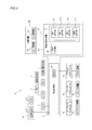
- FIG. 2 is a block diagram of the vehicle system according to the present embodiment.
- FIG. 3 is a flowchart showing processing executed by the vehicle communication system according to this embodiment.
- FIG. 4 is a diagram showing an example of a message displayed on the vehicle display device according to the present embodiment.
- FIG. 5 is a diagram showing an example of a message displayed on the vehicle display device according to the present embodiment.
- FIG. 6 is a diagram showing an example of a message displayed on the vehicle display device according to the present embodiment.
- FIG. 7 is a diagram showing an example of a message displayed on the vehicle display device according to the present embodiment.
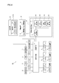
- FIG. 8 is a block diagram of a vehicle system according to a modification.
- FIG. 1 is a side view of a vehicle including the vehicle communication system according to the present embodiment.
- FIG. 2 is a block diagram of the vehicle system according to the present embodiment.
- FIG. 3 is a flow
- FIG. 9 is a diagram showing an example of a message displayed on the vehicle display device according to the present embodiment.
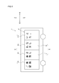
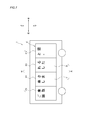
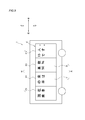
- FIG. 10 is a schematic diagram showing the structure of the display unit of the vehicle display device provided in the vehicle according to the present embodiment.
- 11 is a cross-sectional view taken along the line AA in FIG.
- FIG. 12 is a schematic diagram showing the structure of the display unit of the vehicular display device according to the modification.
- “horizontal direction” and “vertical direction” will be appropriately referred to. These directions are relative directions set for the vehicle 1 illustrated in FIG. 1.
- the “vertical direction” is a direction including “upward direction” and “downward direction”.
- the “left-right direction” is a direction including the “left direction” and the “right direction”.
- vehicle outside direction and “vehicle inside direction” will be referred to as appropriate.
- the “outside vehicle direction” means a direction toward the outside of the vehicle 1.
- the “in-vehicle direction” means a direction toward the inside of the vehicle 1.
- FIG. 1 is a side view of the vehicle 1.
- the vehicle 1 is a vehicle that can travel in an automatic driving mode and includes a movable device 30 and a display device 40.
- the vehicle 1 can travel to the right or left.
- the movable device 30 includes a first opening/closing portion 31 and a second opening/closing portion 32.
- the first opening/closing part 31 and the second opening/closing part 32 can function as a door provided in the vehicle 1, for example.
- the first opening/closing part 31 and the second opening/closing part 32 can be opened/closed in the left-right direction with respect to the vehicle 1.
- first opening/closing part 31 and the second opening/closing part 32 may be opened/closed not only in the horizontal direction but also in the vertical direction.
- the opening/closing method of the first opening/closing part 31 and the second opening/closing part 32 may be a slide type in which the first opening/closing part 31 and the second opening/closing part 32 move linearly, or the first opening/closing part 31 and the second opening/closing part 31 A swing type in which the second opening/closing part 32 rotates may be used.
- the display device 40 includes a display unit 41 and a display control unit 43 (see FIG. 2).
- the display control unit 43 may be provided outside the display device 40.
- the display unit 41 is provided on the side surface of the vehicle 1.
- the display unit 41 may be provided on both side surfaces of the vehicle 1, or may be provided on only one side surface.
- the display unit 41 includes a first display unit 411, a second display unit 412, a third display unit 413, and a fourth display unit 414.
- the first display unit 411 is provided on the first opening/closing unit 31 of the movable device 30.
- the second display unit 412 is provided on the second opening/closing unit 32 of the movable device 30.
- the first display unit 411 is arranged so as to be adjacent to the second display unit 412 and the third display unit 413.
- the second display unit 412 is arranged so as to be adjacent to the first display unit 411 and the fourth display unit 414.
- the third display unit 413 is arranged so as to be adjacent to the first display unit 411.
- the fourth display unit 414 is arranged so as to be adjacent to the second display unit 412.
- FIG. 2 illustrates a block diagram of the vehicle system 2.
- the vehicle system 2 includes a vehicle control unit 3, a sensor 5, a camera 6, a radar 7, an HMI (Human Machine Interface) 8, a GPS (Global Positioning System) 9, and a radio.
- the communication unit 10 and the map information storage unit 11 are provided.
- the vehicle system 2 includes a steering actuator 12, a steering device 13, a brake actuator 14, a brake device 15, an accelerator actuator 16, an accelerator device 17, a voice detection unit 18, a movable device 30, and a display device. And 40.
- the vehicle system 2 includes a vehicle communication system 20.
- the vehicle communication system 20 includes a vehicle control unit 3, a detection unit 19 including a camera 6 and a voice detection unit 18, and a display device 40.
- the vehicle control unit 3 is configured to control the traveling of the vehicle 1.
- the vehicle control unit 3 is composed of an electronic control unit (ECU).
- the electronic control unit includes a processor such as a CPU (Central Processing Unit), a ROM (Read Only Memory) in which various vehicle control programs are stored, and a RAM (Random Access Memory) in which various vehicle control data are temporarily stored. It is composed by.
- the processor is configured to expand a program designated from various vehicle control programs stored in the ROM on the RAM and execute various processes in cooperation with the RAM.
- the vehicle control unit 3 also stores information about the passenger capacity of the vehicle 1.
- the passenger capacity of the vehicle 1 refers to the maximum number of passengers in the vehicle 1.
- the sensor 5 includes an acceleration sensor, a speed sensor, a gyro sensor, and the like.
- the sensor 5 is configured to detect the traveling state of the vehicle 1 and output the traveling state information to the vehicle control unit 3.
- the sensor 5 is a seating sensor that detects whether the driver is sitting in the driver's seat, a face orientation sensor that detects the direction of the driver's face, an external weather sensor that detects external weather conditions, and whether or not there is a person in the vehicle.
- a human sensor for detection may be further provided.
- the sensor 5 may further include a motion sensor that can detect whether or not there is a person around the vehicle 1.
- the camera 6 is a camera including an image sensor such as a CCD (Charge-Coupled Device) or a CMOS (Complementary MOS).
- the radar 7 is a millimeter wave radar, a microwave radar, a laser radar, or the like.
- the camera 6 and/or the radar 7 is configured to detect a surrounding environment of the vehicle 1 (another vehicle, a pedestrian, a road shape, a traffic sign, an obstacle, etc.) and output the surrounding environment information to the vehicle control unit 3. ing.
- the camera 6 is also provided inside the vehicle 1.
- the camera 6 provided inside the vehicle 1 can image the inside of the vehicle 1.
- the camera 6 can convert the captured image into image data by, for example, A/D conversion.
- the image data is transmitted to the vehicle control unit 3.
- the voice detection unit 18 includes a microphone.
- the microphone can detect the voice of the subject around the vehicle 1.
- the target person is, for example, a person (boarding candidate) waiting for a bus, a taxi, a shared car, or the like at a stop.
- the voice detection unit 18 can convert the detected voice into voice data by, for example, A/D conversion.
- the vehicle control unit 3 includes an analysis unit 21.
- the analysis unit 21 can perform image analysis on the image data output from the camera 6.
- the analysis unit 21 can analyze the behavior intention of the boarding candidate by analyzing the image data of the boarding candidate captured by the camera 6.
- the analysis unit 21 analyzes the action intention of the boarding candidate from the gesture taken by the boarding candidate, for example.
- the analysis unit 21 can determine the number of people (the number of passengers) who are in the vehicle 1 by analyzing the image data, for example.
- the analysis unit 21 can calculate the congestion rate ⁇ of the vehicle 1 from the passenger capacity ⁇ of the vehicle 1 and the number of passengers ⁇ .
- the calculation method of the congestion rate ⁇ is as shown in the following Expression 1.
- the analysis unit 21 can also analyze the voice data output from the voice detection unit 18.
- the analysis unit 21 detects, for example, a component indicating the behavior intention of the target person in the vicinity of the vehicle 1 from the voice data detected by the voice detection unit 18, and analyzes the behavior intention of the target person.
- the HMI 8 is composed of an input unit that accepts an input operation from the driver and an output unit that outputs driving information and the like to the driver.
- the input unit includes a steering wheel, an accelerator pedal, a brake pedal, a driving mode switching switch that switches the driving mode of the vehicle 1, and the like.
- the output unit is a display that displays various traveling information.
- the GPS 9 is configured to acquire the current position information of the vehicle 1 and output the acquired current position information to the vehicle control unit 3.
- the wireless communication unit 10 receives information (for example, driving information and the like) on other vehicles around the vehicle 1 from the other vehicle and transmits information (for example, driving information and the like) on the vehicle 1 to the other vehicle. Configured (vehicle-to-vehicle communication). Further, the wireless communication unit 10 is configured to receive infrastructure information from infrastructure equipment such as a traffic light and a sign light, and transmit the traveling information of the vehicle 1 to the infrastructure equipment (road-vehicle communication). The vehicle 1 may communicate directly with another vehicle or infrastructure equipment, or may communicate via a wireless communication network.
- the map information storage unit 11 is an external storage device such as a hard disk drive that stores map information, and is configured to output the map information to the vehicle control unit 3.
- the first opening/closing part 31 and the second opening/closing part 32 of the movable device 30 open/close in the left-right direction based on an instruction signal transmitted from the vehicle control part 3.
- the first opening/closing part 31 and the second opening/closing part 32 can be opened/closed while interlocking with each other, or can be opened/closed independently of each other.
- the display device 40 includes a display unit 41 and a display control unit 43.
- the display unit 41 includes a display capable of displaying various information. Examples of the display include a liquid crystal display, a plasma display, an EL (electroluminescence) display, and a micro LED display.
- the various information includes, for example, traveling information of the vehicle 1, information regarding advertisements, messages to pedestrians in the vicinity of the vehicle 1, and the like.
- the display control unit 43 is composed of an electronic control unit (ECU).
- the display control unit 43 generates image data and control signals for displaying various information on the display unit 41.
- the display control unit 43 controls the display unit 41 by transmitting the signal to the display unit 41.
- the vehicle control unit 3 uses at least the steering control signal, the accelerator control signal, and the brake control signal based on the traveling state information, the surrounding environment information, the current position information, the map information, and the like. Generate one automatically.
- the steering actuator 12 is configured to receive a steering control signal from the vehicle control unit 3 and control the steering device 13 based on the received steering control signal.
- the brake actuator 14 is configured to receive a brake control signal from the vehicle control unit 3 and control the brake device 15 based on the received brake control signal.
- the accelerator actuator 16 is configured to receive an accelerator control signal from the vehicle control unit 3 and control the accelerator device 17 based on the received accelerator control signal.
- the traveling of the vehicle 1 is automatically controlled by the vehicle system 2.
- the vehicle control unit 3 when the vehicle 1 travels in the manual driving mode, the vehicle control unit 3 generates a steering control signal, an accelerator control signal and a brake control signal according to a manual operation of the driver on the accelerator pedal, the brake pedal and the steering wheel.
- the steering control signal, the accelerator control signal, and the brake control signal are generated by the driver's manual operation, so that the traveling of the vehicle 1 is controlled by the driver.
- the operation mode includes an automatic operation mode and a manual operation mode.
- the automatic driving mode includes a fully automatic driving mode, an advanced driving support mode, and a driving support mode.
- the vehicle system 2 In the fully automatic driving mode, the vehicle system 2 automatically performs all traveling control such as steering control, brake control, and accelerator control, and the driver is not in a state where the vehicle 1 can be driven.
- the vehicle system 2 In the advanced driving support mode, the vehicle system 2 automatically performs all traveling control such as steering control, brake control, and accelerator control, and the driver does not drive the vehicle 1 although the vehicle 1 can drive the vehicle.
- the vehicle system 2 In the driving support mode, the vehicle system 2 automatically performs a part of traveling control among steering control, braking control, and accelerator control, and the driver drives the vehicle 1 under the driving support of the vehicle system 2.
- the vehicle system 2 In the manual driving mode, the vehicle system 2 does not automatically perform the traveling control, and the driver drives the vehicle 1 without driving assistance of the vehicle system 2.
- the driving mode of the vehicle 1 may be switched by operating the driving mode switch.
- the vehicle control unit 3 sets the driving modes of the vehicle 1 to four driving modes (fully automatic driving mode, advanced driving support mode, driving support mode, manual driving mode) in accordance with the driver's operation of the driving mode changeover switch. ) Switch between.
- the driving mode of the vehicle 1 is automatically set based on the information about the travelable section in which the autonomous vehicle can travel, the prohibited section in which the autonomous vehicle is prohibited to travel, or the information about the external weather condition. It may be switched.
- the vehicle control unit 3 switches the operation mode of the vehicle 1 based on these pieces of information.
- the driving mode of the vehicle 1 may be automatically switched by using a seating sensor, a face orientation sensor, or the like. In this case, the vehicle control unit 3 switches the driving mode of the vehicle 1 based on the output signals from the seating sensor and the face orientation sensor.
- FIG. 3 is a flowchart showing processing executed by the vehicle communication system 20 according to this embodiment.
- 4 to 7 are diagrams showing examples of messages displayed on the vehicle display device 40 according to the present embodiment.
- the vehicle control unit 3 When the vehicle 1 is a bus and there is no person getting off from the vehicle 1 at a stop such as a bus stop, when the vehicle 1 approaches the stop such as a bus stop, the vehicle control unit 3 causes the camera 6 to operate as shown in FIG. It is determined whether there is a target person (boarding candidate) at the stop based on the surrounding environment information regarding the vehicle 1 output from (STEP 01). When vehicle control unit 3 determines that there are no boarding candidates at the stop (NO in STEP01), vehicle control unit 3 controls vehicle 1 to pass through the stop (STEP02). After that, the vehicle control unit 3 ends this processing.
- the vehicle control unit 3 determines that there is a boarding candidate at the stop (YES in STEP01)
- the vehicle control unit 3 tentatively determines that the vehicle 1 needs to be stopped at the stop.
- the vehicle control unit 3 generates an instruction signal for causing the display unit 41 of the display device 40 to display a message asking the boarding candidate about the boarding intention (an example of a behavioral intention), and the display control unit outputs the instruction signal.
- Sent to 43 The display control unit 43 controls the display unit 41 to display the message based on the instruction signal (STEP 03). In this case, the display unit 41 displays a message such as "Do you want to board?" as illustrated in FIG.
- the vehicle control unit 3 determines whether or not the detection unit 19 detects a motion indicating the boarding intention of the boarding candidate (STEP 04).
- the motion is, for example, a gesture or a voice.
- Gestures indicating the intention to board are, for example, a gesture of drawing a circle with a hand, a gesture of raising a hand on the hand, and the like.
- the gesture indicating the intention not to get on is, for example, a gesture of crossing hands.
- the vehicle control unit 3 sends a message to the boarding candidate to express the boarding intention.
- An instruction signal to be displayed on the display unit 41 of the display device 40 is generated, and the instruction signal is transmitted to the display control unit 43.
- the display control unit 43 controls the display unit 41 to display the message based on the instruction signal (STEP 05). In this case, the display unit 41 displays a message such as "Please show your intention again" as illustrated in FIG.
- the analysis unit 21 of the vehicle control unit 3 causes the information related to the motion detected by the detection unit 19 (image data or audio data). Etc.), it is judged whether or not it is possible to analyze the boarding intention of the boarding candidate (STEP 06).
- the vehicle control unit 3 informs the boarding candidate of the boarding intention.
- An instruction signal for causing the display unit 41 of the display device 40 to display a message urgently indicating is generated, and the instruction signal is transmitted to the display control unit 43.
- the display control unit 43 controls the display unit 41 to display the message based on the instruction signal (STEP 07). In this case, the display unit 41 displays a message such as "Please show your intention again" as illustrated in FIG.
- the motion in which the analysis unit 21 cannot analyze the boarding intention of the boarding candidate is, for example, a gesture of slightly raising the hand, a voice such as "May board".
- the analysis unit 21 can analyze the boarding intention of the boarding candidate from the information detected by the detection unit 19 (YES in STEP 06), the analysis unit 21 will board the vehicle based on the information detected by the detection unit 19. It is determined whether or not the candidate has the intention to board the vehicle 1 (STEP 08). If the analysis unit 21 determines that the boarding candidate does not have the intention to board the vehicle 1 (NO in STEP 08), the vehicle control unit 3 determines that the vehicle 1 has the boarding candidate's intention to board. An instruction signal for causing the display unit 41 of the display device 40 to display a message indicating that the user has not recognized is generated, and the instruction signal is transmitted to the display control unit 43.
- the display control unit 43 controls the display unit 41 to display the message based on the instruction signal (STEP 09). In this case, the display unit 41 displays a message such as “I have recognized that you will not board” as shown in FIG. When STEP09 is executed, the vehicle control unit 3 ends this processing.
- the vehicle control unit 3 determines that the vehicle 1 has the boarding candidate's intention to board.
- An instruction signal for causing the display unit 41 of the display device 40 to display a message indicating that it has been recognized is generated, and the instruction signal is transmitted to the display control unit 43.
- the display control unit 43 controls the display unit 41 to display the message based on the instruction signal (STEP 10). In this case, as shown in FIG. 7, the display unit 41 displays a message such as "I recognize that you are getting on.”
- STEP 10 is executed, the vehicle control unit 3 ends this processing.
- the detection unit 19 detects the boarding candidate around the vehicle 1 and the motion of the boarding candidate.
- the analysis unit 21 analyzes the behavior intention such as the boarding intention of the boarding candidate based on the motion detected by the detection unit 19.
- the display control unit 43 causes the display unit 41 to display the action intention of the boarding candidate based on the analysis result of the analysis unit 21. Therefore, for example, when the boarding candidate makes a gesture or utterance indicating the action intention not to board the vehicle 1, the vehicle 1 recognizes on the display unit 41 that the boarding candidate does not intend to board the vehicle 1. Is displayed. In this way, the boarding candidate can transmit the action intention to the vehicle 1 by a simple ideographic method such as a gesture or utterance.
- the detection unit 19 is provided in the vehicle 1. Therefore, the vehicle 1 can detect the motion of the boarding candidate near the vehicle 1 and analyze the action intention of the boarding candidate.
- the detection unit 19 when the detection unit 19 cannot detect the motion of the boarding candidate, or when the motion detected by the detection unit 19 is ambiguous, the boarding candidate is requested to express his/her intention to act. A message for prompting can be displayed on the display unit 41. Therefore, the certainty of communication between the vehicle 1 and the target person is improved.
- FIG. 8 is a block diagram of a vehicle system 2A including the vehicle communication system 20A.
- the communication system 20A according to the modified example is different from the communication system 20 in that the detection unit 19A is provided in the stop 500 and the stop 500 and the wireless communication unit 10 can communicate with each other.
- the detector 19A includes a camera 6A and a voice detector 18A.
- the configuration of the camera 6A is similar to that of the camera 6.
- the configuration of the voice detection unit 18A is similar to that of the voice detection unit 18.
- the flow of processing executed by the vehicle communication system 20A is the same as the flow illustrated in FIG. Therefore, the overlapping description will be omitted as appropriate.
- the vehicle control unit 3 determines whether there is a boarding candidate at the stop 500 based on the surrounding environment information of the stop 500 output from the detection unit 19A provided in the stop 500 (Fig. 3 STEP01).
- the vehicle control unit 3 determines that there is no candidate for boarding at the stop 500 (NO in STEP01 of FIG. 3 )
- the vehicle control unit 3 executes STEP02 of FIG. 3 and thereafter ends this processing.
- the vehicle communication system 20A executes STEP03 of FIG.
- the vehicle control unit 3 determines whether or not the detection unit 19A detects a motion indicating the boarding intention of the boarding candidate (STEP 04 in FIG. 3).
- the vehicle communication system 20A executes STEP05 of FIG.
- the vehicle communication system 20A executes STEP06 of FIG.
- STEP06 to STEP10 of FIG. 3 there is no difference between the vehicle communication system 20 and the vehicle communication system 20A, and a description thereof will be omitted.
- the detection unit 19A is provided in the stop 500. Therefore, when the vehicle 1 is provided with the detection unit 19, even if the boarding candidate is far from the vehicle 1 to the extent that the detection unit 19 of the vehicle 1 cannot detect the boarding candidate, the boarding candidate does Can be transmitted to 1.
- the camera 6 provided inside the vehicle 1 images the inside of the vehicle 1.
- the camera 6 converts the captured image into image data by A/D conversion, and transmits the image data to the vehicle control unit 3.
- the analysis unit 21 of the vehicle control unit 3 determines the number of passengers of the vehicle 1 based on the image data.
- the analysis unit 21 calculates the congestion rate of the vehicle 1 from the passenger capacity of the vehicle 1 and the number of passengers.
- the vehicle control unit 3 For example, if the vehicle 1 has 30 passengers and 15 passengers, the congestion rate is 50%.
- the vehicle control unit 3 generates an instruction signal for causing the display unit 41 of the display device 40 to display information (message) regarding the number of passengers of the vehicle 1 and the congestion rate of the vehicle 1, and the display control of the instruction signal is performed. It is transmitted to the unit 43.
- the display control unit 43 controls the display unit 41 so as to display the information based on the instruction signal. In this case, as shown in FIG. 9, the display unit 41 displays a message such as “currently the number of passengers is 15 people.
- the passenger ratio is 50%”.
- the vehicle communication systems 20 and 20A it is possible to display information regarding the number of passengers and the congestion rate of the vehicle 1 on the display unit 41. Therefore, the boarding candidate can know the congestion situation of the vehicle 1 before getting on the vehicle 1. Then, the boarding candidate can express the intention to act or not to board the vehicle 1 after knowing the congestion state of the vehicle 1.
- FIG. 10 is a schematic diagram for illustrating the structure of the display unit 41 of the display device 40 included in the vehicle 1 according to the first embodiment.
- FIG. 11 is a sectional view taken along the line AA in FIG.
- the display unit 41 of the display device 40 includes a substrate 50, a semiconductor light emitting unit 60, and a light shielding unit 63.
- the substrate 50 is transparent and has a sheet shape.
- a glass material such as silica glass, borosilicate glass, or alkali-free borosilicate glass, or a resin material such as polyethylene terephthalate, polyethylene naphthalate, polypropylene, or cycloolefin polymer can be used.
- the substrate 50 includes a first surface 51 facing the vehicle exterior direction and a second surface 52 facing the vehicle interior direction. In other words, the second surface 52 is the surface on the back side of the first surface 51.
- the semiconductor light emitting unit 60 is, for example, an OLED (Organic Light Emitting Diode), a micro LED, or the like.
- the semiconductor light emitting unit 60 includes a first light emitting element 61 and a second light emitting element 62.
- the plurality of first light emitting elements 61 (a part of the semiconductor light emitting unit 60) are arranged on the first surface 51 of the substrate 50.
- the plurality of second light emitting elements 62 (a part of the semiconductor light emitting unit 60) are arranged on the second surface 52 of the substrate 50.
- the first light emitting elements 61 and the second light emitting elements 62 are connected to each other by power feeding conductors formed on the substrate 50.
- the first light emitting element 61 and the second light emitting element 62 emit light by being supplied with power.
- the semiconductor light emitting unit 60 When the semiconductor light emitting unit 60 is an OLED, the semiconductor light emitting unit 60 includes a first substrate that functions as a cathode that supplies electrons, an organic layer, a second substrate, and an electrode layer that functions as an anode that receives the electrons. Have.
- the first substrate is arranged on the substrate 50 side.
- the organic layer and the electrode layer are arranged between the first substrate and the second substrate.
- the organic layer is arranged inside the vehicle 1 with respect to the electrode layer.
- the semiconductor light emitting unit 60 when the semiconductor light emitting unit 60 is a micro LED, the semiconductor light emitting unit 60 includes an LED cell.
- the LED cell includes an n-type semiconductor layer, an active layer, and a p-type semiconductor layer.
- the light shield 63 includes a first light shield 64 and a second light shield 65.
- the first light shielding portion 64 is arranged on the first surface 51 of the substrate 50.
- the second light shielding unit 65 is arranged on the second surface 52 of the substrate 50.
- the light shielding portion 63 includes a light shielding material.
- the light-shielding material is, for example, an insulating organic material such as acrylic resin or polyimide resin, or an insulating inorganic material such as silicon oxide or silicon nitride.
- the light shielding portion 63 is, for example, a light shielding plate capable of reflecting the light emitted from the semiconductor light emitting portion 60.
- the reflectance of the first light shielding portion 64 is higher than the reflectance of the first light emitting element 61
- the reflectance of the second light shielding portion 65 is higher than the reflectance of the second light emitting element 62.
- the first light shield 64 is provided on the substrate 50 at a position on the back side corresponding to the position where the second light emitting element 62 is provided.
- the second light shielding portion 65 is provided on the substrate 50 at a position on the back side corresponding to the position where the first light emitting element 61 is provided.
- the height h1 of the first light emitting element 61 is about 0.1 mm.
- the height h2 of the first light shielding portion 64 is about 0.2 mm. As described above, the height h2 of the first light shielding portion 64 is higher than the height h1 of the first light emitting element 61.
- the height h1 of the first light emitting element 61 is equal to the height h3 of the second light emitting element 62.
- the height h2 of the first light shielding portion 64 is equal to the height h4 of the second light shielding portion 65. Therefore, the height h4 of the second light shielding portion 65 is higher than the height h3 of the second light emitting element 62.
- the first light emitting elements 61 and the first light shielding portions 64 are alternately arranged in the left-right direction at regular intervals. It is arranged in a way. Further, in the plurality of first light emitting elements 61 and the plurality of first light shielding portions 64, the first light emitting elements 61 and the first light shielding portions 64 are alternately arranged regularly at predetermined intervals in the vertical direction. .. In the present embodiment, the predetermined distance in the left-right direction between the first light emitting element 61 and the first light shielding portion 64 is d1. The area ratio of the plurality of first light emitting elements 61 and the plurality of first light shielding portions 64 to the area of the first surface 51 of the substrate 50 is less than 90%.
- the second light emitting elements 62 and the second light shielding portions 65 are alternately arranged in the left-right direction at regular intervals. It is arranged in a way.
- the plurality of second light emitting elements 62 and the plurality of second light shielding portions 65 are similar to the first light emitting element 61 and the first light shielding portion 64 in that the second light emitting element 62 and the second light shielding portion 65 are arranged in the vertical direction. Alternately, they are regularly arranged at predetermined intervals.
- the predetermined distance in the left-right direction between the second light emitting element 62 and the second light shielding portion 65 is d2.
- the ratio of the areas of the plurality of second light emitting elements 62 and the plurality of second light shielding portions 65 to the area of the second surface 52 of the substrate 50 is less than 90%.
- the light transmittance X on the first surface 51 of the substrate 50 or the second surface 52 of the substrate 50 is calculated by the following equation 2 when the transmittance of the substrate 50 alone is assumed to be 100%.
- a in Expression 2 represents the area of the first surface 51 or the area of the second surface 52
- B represents the total area of the first light emitting element 61 and the first light shielding portion 64 or the second light emitting element 62 and the second light shielding. It represents the total area of the part 65.
- the substrate 50 according to the present embodiment can be used as a light transmitting member having a transmittance of 10% or more.
- the distance d1 and the distance d2 have the same length. That is, the distance between the first light emitting elements 61 and the distance between the second light emitting elements 62 are the same.
- the first light emitting element 61 (a part of the semiconductor light emitting unit 60) has a light transmittance of 10% or more in the display device 40 on the first surface 51 of the substrate 50. Are arranged at predetermined intervals.
- the second light emitting elements 62 (a part of the semiconductor light emitting unit 60) are arranged on the second surface 52 of the substrate 50 at predetermined intervals so that the light transmittance of the display device 40 is 10% or more. ing.
- the semiconductor light emitting unit 60 can display a desired display on both surfaces of the substrate 50. Further, the substrate 50 can be used as a light transmitting member having a transmittance of 10% or more.
- the interval between the first light emitting elements 61 and the interval between the second light emitting elements 62 are the same. Therefore, the display density of the first surface 51 and the display density of the second surface 52 of the substrate 50 can be made equal.
- the height h2 of the first light shielding portion 64 is higher than the height h1 of the first light emitting element 61, so that the light emitted from the first light emitting element 61 is emitted from other first light emitting elements 61. It does not interfere with the light emitted from the light emitting element 61. Therefore, a desired display surface of the display device 40 facing the outside of the vehicle 1 can be provided without being affected by the light emitted from the plurality of first light emitting elements 61 arranged on the first surface 51 of the substrate 50. Information can be displayed in high quality.
- the first light shielding portion 64 can reflect the light emitted from the second light emitting element 62 in the vehicle interior direction. Therefore, the utilization efficiency of light on the first surface 51 can be improved. Further, the second light shielding unit 65 can reflect the light emitted from the first light emitting element 61 in the vehicle exterior direction. Therefore, the utilization efficiency of light on the second surface 52 can be improved.
- FIG. 12 is a schematic diagram for illustrating the structure of the display unit 41A of the vehicle display device 40A.
- the height of the first light emitting element 61A and the height of the second light emitting element 62A are equal to the height of the light shielding portion 63, the first plate-shaped member 70 and the second It is different from the display unit 41 of the display device 40 in that the plate-shaped member 71 is provided and the film 80 is provided.
- the first plate member 70 and the second plate member 71 may be made of translucent glass or translucent resin material. Therefore, the first plate-shaped member 70 and the second plate-shaped member 71 have translucency.
- the first plate-shaped member 70 is arranged outward of the vehicle with respect to the first light emitting element 61A and the first light shielding portion 64. A part of the first plate member 70 is in contact with the first light emitting element 61A and the first light shielding portion 64.
- the second plate-shaped member 71 is arranged inward of the vehicle with respect to the second light emitting element 62A and the second light shielding portion 65. A part of the second plate-shaped member 71 is in contact with the second light emitting element 62A and the second light shielding portion 65.
- the film 80 includes a base material, an adhesive layer, and an antistatic layer.
- the substrate is located between the adhesive layer and the antistatic layer.
- the base material can be made of, for example, a resin material such as polyester.
- the base material has translucency.
- the pressure-sensitive adhesive layer may be composed of a pressure-sensitive adhesive composition containing a pressure-sensitive adhesive such as an acrylic pressure-sensitive adhesive.
- the antistatic layer is positioned in a direction in which it can contact the first plate member 70 or the second plate member 71.
- the antistatic layer contains an antistatic agent.
- the thickness of the film 80 is, for example, about 1 mm.
- the film 80 is arranged so as to cover the first light emitting element 61A and the first light shielding portion 64.
- a space is formed by the first plate member 70 and the film 80.
- the second light emitting element 62A and the second light shielding portion 65 are covered with the film 80, a space is formed by the second plate member 71 and the film 80. These spaces are filled with an adhesive.
- the first plate member 70 or the second plate member 71 functions as the surface of the display device 40. Therefore, both surfaces of the display device 40 are smooth.
- the semiconductor light emitting unit 60 that is, the first light emitting element 61A and the second light emitting element 62A
- the light shielding unit 63 that is, the first light shielding unit 64 and the second light shielding unit 65
- the film 80 covers the semiconductor light emitting unit 60 and the light shielding unit 63 between the substrate 50 and the first plate member 70 or the second plate member 71. Therefore, it is possible to prevent the semiconductor light emitting unit 60 and the light shielding unit 63 from being damaged.
- various messages from the vehicle 1 to the boarding candidate and information regarding the congestion status of the vehicle 1 are displayed on the display unit 41, but are not limited to this example.
- the information is transmitted to the communication terminal carried by the boarding candidate and displayed on the display unit of the communication terminal.
- the information may be displayed.
- the boarding candidate when the boarding candidate expresses with a gesture or the like that the boarding candidate does not have the intention to board the vehicle 1, the boarding candidate uses the communication terminal carried by the boarding candidate that the vehicle 1 recognizes the intention. Can be confirmed via.
- the detection unit 19 is provided in the vehicle 1. Further, in the vehicle system 2A described above, the detection unit 19A is provided in the stop 500. However, it is not limited to these examples.
- the detection units 19 and 19A may be provided, for example, in a communication terminal carried by a boarding candidate.
- the vehicle 1 is a bus, but it is not limited to this.
- the vehicle 1 may be, for example, a vehicle (share car) that can be shared by a plurality of people.
- the camera 6 of the detection unit 19 or the camera 6A of the detection unit 19A images a specific boarding candidate (for example, a person who is closest to the cameras 6 and 6A) near the stop. It may be configured as follows.
- the display control unit 43 may cause the display unit 41 to display the image of the boarding candidate captured by the cameras 6 and 6A together with various messages. In this case, for example, even if there are a plurality of boarding candidates at the stop, the boarding candidate can easily recognize which boarding candidate the message displayed on the display unit 41 is.
- the analysis unit 21 is provided in the vehicle control unit 3, but is not limited to this example.
- the vehicle display device 4 may include the analysis unit 21.
- the vehicle systems 2 and 2A include the cameras 6 and 6A and the voice detection units 18 and 18A, but the vehicle systems 2 and 2A include the cameras 6 and 6A and the voice detection units 18 and 18A. Only one of the above may be provided.
- the vehicle control unit 3 determines whether there is a boarding candidate at the stop 500 based on the surrounding environment information of the stop 500 output from the detection unit 19A provided at the stop 500. Judge whether, but not limited to this example.
- the vehicle control unit 3 may combine the information transmitted from the camera 6 and the voice detection unit 18 provided in the vehicle 1 with the information transmitted from the stop 500 to make the determination in a composite manner.
- the first light-shielding portion 64 is provided on the first surface 51 and the second light-shielding portion 65 is provided on the second surface 52 of the substrate 50, but the present invention is not limited to this example. Absent.
- the light shielding portion 63 may be provided on only one of the first surface 51 and the second surface 52.
- the first light-shielding portion 64 is higher than the first light emitting element 61, and the second light-shielding portion 65 is higher than the second light emitting element 62.
- the present invention is not limited to this example. Absent.
- the first light shielding portion 64 is higher than the first light emitting element 61, but the second light shielding portion 65 may not be higher than the second light emitting element 62.
- the second light shielding portion 65 is higher than the second light emitting element 62, but the first light shielding portion 64 may not be higher than the first light emitting element 61.
- the height of the first light shielding portion 64 is equal to the height of the first light emitting element 61A and the height of the second light shielding portion 65 is equal to the height of the second light emitting element 62A.
- the present invention is not limited to this example.
- the first light shielding portion 64 may be higher than the first light emitting element 61A
- the second light shielding portion 65 may be higher than the second light emitting element 62.
- the space formed by the first light emitting element 61A and the first plate-shaped member 70 and the space formed by the second light emitting element 62A and the second plate-shaped member 71 are respectively filled with an adhesive. ..
- the height h1 of the first light emitting element 61 is equal to the height h3 of the second light emitting element 62, but is not limited to this example.
- the height h1 of the first light emitting element 61 may be different from the height h3 of the second light emitting element 62.
- the height h2 of the first light shielding portion 64 is equal to the height h4 of the second light shielding portion 65, but the present invention is not limited to this example.
- the height h2 of the first light shielding portion 64 may be different from the height h4 of the second light shielding portion 65.
- the light emitted from the semiconductor light emitting unit 60 is described by using the example of being reflected by the light shielding unit 63, but the present invention is not limited to this example.
- the light emitted from the semiconductor light emitting unit 60 may be absorbed by the light shielding unit 63.
- the display unit 41 of the display device 40 does not include the film 80, but is not limited to this example.
- the display unit 41 of the display device 40 may include the film 80.
- the above-described vehicle display device 40A includes the first plate-shaped member 70 and the second plate-shaped member 71, but is not limited to this example.
- the display device 40A may be a display device including only one of the first plate member 70 and the second plate member 71.
Landscapes
- Engineering & Computer Science (AREA)
- Mechanical Engineering (AREA)
- General Engineering & Computer Science (AREA)
- Physics & Mathematics (AREA)
- Transportation (AREA)
- Microelectronics & Electronic Packaging (AREA)
- Optics & Photonics (AREA)
- Automation & Control Theory (AREA)
- General Physics & Mathematics (AREA)
- Fittings On The Vehicle Exterior For Carrying Loads, And Devices For Holding Or Mounting Articles (AREA)
- Fastening Of Light Sources Or Lamp Holders (AREA)
- Lighting Device Outwards From Vehicle And Optical Signal (AREA)
- Traffic Control Systems (AREA)
Abstract
車両(1)の周囲にいる対象者及び対象者のモーションを検知可能な検知部(19)と、検知部(19)により取得された情報に基づき対象者の行動意思を解析可能な解析部(21)と、所定の情報を表示可能な表示部(41)と、解析部(21)による解析結果に基づき、表示部(41)を制御可能な表示制御部(43)と、を備える車両用コミュニケーションシステム(20)であって、表示制御部(43)は、解析部(21)が解析した対象者の行動意思を表示部(41)に表示させる。
Description
本発明は、車両用コミュニケーションシステム、車両用表示装置および車両に関する。
現在、自動車の自動運転技術の研究が各国で盛んに行われており、自動運転モードで車両(以下、「車両」は自動車のことを指す。)が公道を走行することができるための法整備が各国で検討されている。ここで、自動運転モードでは、車両システムが車両の走行を自動的に制御する。具体的には、自動運転モードでは、車両システムは、カメラ、レーダ(例えば、レーザレーダやミリ波レーダ)等のセンサから得られる車両の周辺環境を示す情報(周辺環境情報)に基づいてステアリング制御(車両の進行方向の制御)、ブレーキ制御及びアクセル制御(車両の制動、加減速の制御)のうちの少なくとも1つを自動的に行う。一方、以下に述べる手動運転モードでは、従来型の車両の多くがそうであるように、運転者が車両の走行を制御する。具体的には、手動運転モードでは、運転者の操作(ステアリング操作、ブレーキ操作、アクセル操作)に従って車両の走行が制御され、車両システムはステアリング制御、ブレーキ制御及びアクセル制御を自動的に行わない。尚、車両の運転モードとは、一部の車両のみに存在する概念ではなく、自動運転機能を有さない従来型の車両も含めた全ての車両において存在する概念であって、例えば、車両制御方法等に応じて分類される。
このように、将来において、公道上では自動運転モードで走行中の車両(以下、適宜、「自動運転車」という。)と手動運転モードで走行中の車両(以下、適宜、「手動運転車」という。)が混在することが予想される。
自動運転技術の一例として、特許文献1は、先行車に後続車が自動追従走行した自動追従走行システムを開示している。当該自動追従走行システムでは、先行車と後続車の各々が照明システムを備えており、先行車と後続車との間に他車が割り込むことを防止するための文字情報が先行車の照明システムに表示されると共に、自動追従走行である旨を示す文字情報が後続車の照明システムに表示される。
また、特許文献2は、基板上に有機EL発光層が形成された面状光源を有する車両用灯具を開示している。
ところで、自動運転車と手動運転車が混在した自動運転社会では、自動運転に関連する様々な情報(例えば、車両の自動運転モードについての情報等)を描画することによって、歩行者等に視覚的に提示する、いわゆる路面描画ランプが車両に搭載されることが期待されている。この場合、歩行者は描画された情報を視認することで、その情報を把握することができるため、自動運転車に対する歩行者の不安を軽減することができる。一方、歩行者等から、歩行者等の行動意思を自動運転車に対して伝達したいというニーズが存在する。
本開示は、簡易な方法で行動意思を車両に伝達することができる車両用コミュニケーションシステムを提供することを目的とする。
また、特許文献2に係る車両用灯具では、面状光源が配置された表示面から光を出射することができる方向は比較的限定的であった。
本開示は、基板の両面に所望の表示をさせることができ、かつ光透過部材としても利用することができる車両用表示装置を提供することも目的とする。
上記の目的を達成するための一態様に係る車両用コミュニケーションシステムは、
車両の周囲にいる対象者及び前記対象者のモーションを検知可能な検知部と、
前記検知部により取得された情報に基づき前記対象者の行動意思を解析可能な解析部と、
所定の情報を表示可能な表示部と、
前記解析部による解析結果に基づき、前記表示部を制御可能な表示制御部と、を備え、
前記表示制御部は、前記解析部が解析した前記対象者の行動意思を前記表示部に表示させる。
車両の周囲にいる対象者及び前記対象者のモーションを検知可能な検知部と、
前記検知部により取得された情報に基づき前記対象者の行動意思を解析可能な解析部と、
所定の情報を表示可能な表示部と、
前記解析部による解析結果に基づき、前記表示部を制御可能な表示制御部と、を備え、
前記表示制御部は、前記解析部が解析した前記対象者の行動意思を前記表示部に表示させる。
上記構成に係る車両用コミュニケーションシステムによれば、検出部は、車両の周囲にいる対象者及び当該対象者のモーションを検知する。解析部は、検知部により取得された情報に基づき対象者の行動意思を解析することができる。表示制御部は、解析部が解析した対象者の行動意思を表示部に表示させる。このため、例えば、車両の周囲にいる対象者が、車両に乗車しないという行動意思をジェスチャー等で表意すると、対象者が乗車しない意思であることを車両が認識したことを示す文章等が表示部に表示される。
このように、上記構成によれば、簡易な方法で対象者の行動意思を車両に伝達することができる車両用コミュニケーションシステムを提供することができる。
このように、上記構成によれば、簡易な方法で対象者の行動意思を車両に伝達することができる車両用コミュニケーションシステムを提供することができる。
また、上記の目的を達成するための一態様に係る車両用コミュニケーションシステムにおいて、
前記検知部は前記車両に設けられている。
前記検知部は前記車両に設けられている。
上記構成に係る車両用コミュニケーションシステムによれば、検出部は車両に設けられているので、このような車両用コミュニケーションシステムは、車両の近くにいる対象者の行動意思を解析することができる。
また、上記の目的を達成するための一態様に係る車両用コミュニケーションシステムにおいて、
前記検知部は前記車両が停車予定の停車場に設けられている。
前記検知部は前記車両が停車予定の停車場に設けられている。
上記構成に係る車両用コミュニケーションシステムによれば、検出部は車両が停車予定の停車場に設けられているので、このような車両用コミュニケーションシステムは、車両から遠くにいる対象者の行動意思を解析することができる。
また、上記の目的を達成するための一態様に係る車両用コミュニケーションシステムにおいて、
前記表示制御部は、前記車両の内部の混雑状況に関する情報に基づいて、前記表示部を制御する。
前記表示制御部は、前記車両の内部の混雑状況に関する情報に基づいて、前記表示部を制御する。
上記構成に係る車両用コミュニケーションシステムによれば、表示部には車両の内部の混雑状況に関する情報が表示される。したがって、対象者は車両の内部の混雑状況を知った上で行動意思を表意することができる。
また、上記の目的を達成するための一態様に係る車両用コミュニケーションシステムにおいて、
前記表示制御部は、前記表示部に表示させる情報に関連する情報を、前記対象者が携帯する通信端末に送信する。
前記表示制御部は、前記表示部に表示させる情報に関連する情報を、前記対象者が携帯する通信端末に送信する。
上記構成に係る車両用コミュニケーションシステムによれば、表示制御部は、表示部に表示させる情報に関連する情報を、対象者が携帯する通信端末に送信する。このため、例えば、車両の周囲にいる対象者が、車両に乗車しないという行動意思をジェスチャー等で表意すると、対象者が乗車しない意思であることを車両が認識したことを対象者が携帯する通信端末を介して対象者は確認することができる。
また、上記の目的を達成するための一態様に係る車両用コミュニケーションシステムにおいて、
前記検知部が前記対象者のモーションを検知できないとき、又は前記解析部が前記検知部により取得された情報に基づいて前記対象者の行動意思を解析できないとき、
前記表示制御部は、前記対象者に対して行動意思を表意することを促すための表示をするように前記表示部を制御する。
前記検知部が前記対象者のモーションを検知できないとき、又は前記解析部が前記検知部により取得された情報に基づいて前記対象者の行動意思を解析できないとき、
前記表示制御部は、前記対象者に対して行動意思を表意することを促すための表示をするように前記表示部を制御する。
上記構成に係る車両用コミュニケーションシステムによれば、対象者のモーションが検知できないときや、対象者のモーションが曖昧だったとき、対象者に対して行動意思を表意することを促すためのメッセージ等を表示部に表示させる。このため、車両は、対象者に対し、行動意思を表意するよう伝達することができる。この結果、車両と対象者間のコミュニケーションの確実性を高めることができる。
また、上記の目的を達成するための一態様に係る車両用コミュニケーションシステムにおいて、
前記検知部は、前記対象者のジェスチャーを検出するカメラ及び前記対象者が発する音声を検出可能なマイクロフォンの少なくとも一つを有する。
前記検知部は、前記対象者のジェスチャーを検出するカメラ及び前記対象者が発する音声を検出可能なマイクロフォンの少なくとも一つを有する。
上記構成に係る車両用コミュニケーションシステムによれば、検知部は、対象者のジェスチャーを検出するカメラ及び対象者が発する音声を検出可能なマイクロフォンの少なくとも一つを有する。したがって、対象者はジェスチャー及び発声の少なくとも一方により行動意思を表意すれば、車両は対象者の行動意思を認識することができる。
上記の目的を達成するための一態様に係る車両用表示装置は、
光を透過可能な基板と、
前記基板上に設けられた半導体発光部と、
を備える車両用表示装置であって、
前記基板は、第一面と、前記第一面の裏側の面である第二面とを備え、
前記半導体発光部は、前記基板の第一面に設けられた複数の第一発光素子と、前記基板の第二面に設けられた複数の第二発光素子と含み、
前記第一発光素子と、前記第二発光素子とが、当該車両用表示装置における光の透過率が10%以上となるように所定の間隔で配置されている。
光を透過可能な基板と、
前記基板上に設けられた半導体発光部と、
を備える車両用表示装置であって、
前記基板は、第一面と、前記第一面の裏側の面である第二面とを備え、
前記半導体発光部は、前記基板の第一面に設けられた複数の第一発光素子と、前記基板の第二面に設けられた複数の第二発光素子と含み、
前記第一発光素子と、前記第二発光素子とが、当該車両用表示装置における光の透過率が10%以上となるように所定の間隔で配置されている。
上記構成に係る車両用表示装置によれば、半導体発光部は、基板の両面から発光できるように、第一発光素子と第二発光素子を含んでいる。第一発光素子と第二発光素子は、車両用表示装置における光の透過率が10%以上となるように所定の間隔で配置されている。したがって、半導体発光部によって、基板の両面に所望の表示をさせることができる。また、基板を、透過率が10%以上の光透過部材として利用することもできる。
このように、上記構成によれば、基板の両面に所望の表示をさせることができ、かつ基板を光透過部材として利用することもできる車両用表示装置を提供することができる。
このように、上記構成によれば、基板の両面に所望の表示をさせることができ、かつ基板を光透過部材として利用することもできる車両用表示装置を提供することができる。
また、上記の目的を達成するための一態様に係る車両用表示装置において、
前記第一発光素子同士の所定の間隔と前記第二発光素子同士の所定の間隔が同じである。
前記第一発光素子同士の所定の間隔と前記第二発光素子同士の所定の間隔が同じである。
上記構成に係る車両用表示装置によれば、第一発光素子同士の所定の間隔と第二発光素子同士の所定の間隔が同じであるので、基板の両面の表示密度を等しくすることができる。
また、上記の目的を達成するための一態様に係る車両用表示装置は、
前記第一面には、複数の第一遮光部が設けられており、前記第一遮光部は、前記第二発光素子が設けられた位置に対応する裏側の位置に配置されていること、及び、
前記第二面には、複数の第二遮光部が設けられており、前記第二遮光部は、前記第一発光素子が設けられた位置に対応する裏側の位置に配置されていること、の少なくとも一方を満たす。
前記第一面には、複数の第一遮光部が設けられており、前記第一遮光部は、前記第二発光素子が設けられた位置に対応する裏側の位置に配置されていること、及び、
前記第二面には、複数の第二遮光部が設けられており、前記第二遮光部は、前記第一発光素子が設けられた位置に対応する裏側の位置に配置されていること、の少なくとも一方を満たす。
上記構成に係る車両用表示装置によれば、第一発光素子と第二発光素子のそれぞれから出射された光の少なくとも一方が、第一発光素子と第二発光素子の少なくとも一方の裏面に出射されることを防ぐことができる。すなわち、遮光部が設けられている面とは反対の面において、裏面からの光の影響を受けずに、所望の情報を表示画面上に、高画質に表示させることができる。
また、上記の目的を達成するための一態様に係る車両用表示装置は、
前記第一面には、複数の第一遮光部が設けられており、前記第一遮光部は、前記第一発光素子同士の間に配置されており、前記第一遮光部の高さは、前記第一発光素子の高さよりも高いこと、及び、
前記第二面には、複数の第二遮光部が設けられており、前記第二遮光部は、前記第二発光素子同士の間に配置されており、前記第二遮光部の高さは、前記第二発光素子の高さよりも高いこと、の少なくとも一方を満たす。
前記第一面には、複数の第一遮光部が設けられており、前記第一遮光部は、前記第一発光素子同士の間に配置されており、前記第一遮光部の高さは、前記第一発光素子の高さよりも高いこと、及び、
前記第二面には、複数の第二遮光部が設けられており、前記第二遮光部は、前記第二発光素子同士の間に配置されており、前記第二遮光部の高さは、前記第二発光素子の高さよりも高いこと、の少なくとも一方を満たす。
上記構成に係る車両用表示装置によれば、例えば、第一遮光部の高さが、第一発光素子の高さよりも高いとき、第一発光素子から出射される光は、他の第一発光素子から出射される光に対して干渉しない。また、例えば、第二遮光部の高さが、第二発光素子の高さよりも高いとき、第二発光素子から出射される光は、他の第二発光素子から出射される光に対して干渉しない。その結果、基板の両面の少なくとも一方において、同一面上に配置された発光素子から出射される光の影響を受けずに、所望の情報を表示画面上に、高画質に表示させることができる。
また、上記の目的を達成するための一態様に係る車両用表示装置は、
前記第一遮光部の反射率が、前記第一発光素子の反射率よりも高いこと、
及び、
前記第二遮光部の反射率が、前記第二発光素子の反射率よりも高いこと、の少なくとも一方を満たす。
前記第一遮光部の反射率が、前記第一発光素子の反射率よりも高いこと、
及び、
前記第二遮光部の反射率が、前記第二発光素子の反射率よりも高いこと、の少なくとも一方を満たす。
上記構成に係る車両用表示装置によれば、例えば、第一遮光部の反射率が、第一発光素子の反射率よりも高いとき、第一遮光部は、第二発光素子から出射される光を、当該第二発光素子が配置された面方向に反射させることができる。また、例えば、第二遮光部の反射率が、第二発光素子の反射率よりも高いとき、第二遮光部は、第一発光素子から出射される光を、当該第一発光素子が配置された面方向に反射させることができる。このため、当該車両表示装置の両表示面の少なくとも一方における光の利用効率を高めることができる。
また、上記の目的を達成するための一態様に係る車両用表示装置は、
複数の前記第一発光素子を覆うように配置された第一板状部材、及び複数の前記第二発光素子を覆うように配置された第二板状部材の少なくとも一方をさらに備える。
複数の前記第一発光素子を覆うように配置された第一板状部材、及び複数の前記第二発光素子を覆うように配置された第二板状部材の少なくとも一方をさらに備える。
上記構成に係る車両用表示装置によれば、車両用表示装置の両表面の少なくとも一方は滑らかになり好ましい。また、各発光素子の損傷を防ぐことができる。
上記の車両用コミュニケーションシステムと、上記の車両用表示装置と、を備える車両もまた、上記の目的を達成するための本開示の一態様である。
本開示によれば、簡易な方法で行動意思を車両に伝達することができる車両用コミュニケーションシステムおよび車両を提供することができる。
また、本開示によれば、基板の両面に所望の表示をさせることができ、かつ光透過部材としても利用することができる車両用表示装置および車両を提供することもできる。
以下、本開示の実施形態(以下、本実施形態という。)について図面を参照しながら説明する。尚、本実施形態の説明において既に説明された部材と同一の参照番号を有する部材については、説明の便宜上、その説明は省略する。また、本図面に示された各部材の寸法は、説明の便宜上、実際の各部材の寸法とは異なる場合がある。
また、本実施形態の説明では、説明の便宜上、「左右方向」、「上下方向」について適宜言及する。これらの方向は、図1に例示する車両1について設定された相対的な方向である。ここで、「上下方向」は、「上方向」及び「下方向」を含む方向である。「左右方向」は、「左方向」及び「右方向」を含む方向である。また、図11及び図12において、説明の便宜上、「車外方向」、「車内方向」について適宜言及する。「車外方向」とは車両1の外側に向かう方向を意味する。「車内方向」とは車両1の内側に向かう方向を意味する。
本実施形態に係る車両用表示装置40(以下、単に「表示装置40」という。)を備えた車両1について以下に説明する。図1は、車両1の側面図である。車両1は、自動運転モードで走行可能な車両であって、可動装置30と、表示装置40と、を備える。車両1は右方向又は左方向へ走行可能である。可動装置30は、第一開閉部31と、第二開閉部32と、を備える。第一開閉部31及び第二開閉部32は、例えば、車両1に備わるドアとして機能し得る。第一開閉部31及び第二開閉部32は、車両1を基準として、左右方向に開閉可能である。ただし、第一開閉部31及び第二開閉部32は、左右方向に限らず、上下方向に開閉してもよい。また、第一開閉部31及び第二開閉部32の開閉方式は、第一開閉部31及び第二開閉部32が直線的に動くスライド式であってもよいし、第一開閉部31及び第二開閉部32が回転するスイング式であってもよい。
表示装置40は、表示部41と、表示制御部43と、を備える(図2参照)。なお、表示制御部43は、表示装置40の外部にあってもよい。図1に例示されるように、表示部41は、車両1の側面に設けられている。表示部41は、車両1の両側面に設けられていてもよいし、一方の側面にのみ設けられていてもよい。表示部41は、第一表示部411と、第二表示部412と、第三表示部413と、第四表示部414と、を含む。第一表示部411は、可動装置30の第一開閉部31に設けられている。第二表示部412は、可動装置30の第二開閉部32に設けられている。第一表示部411は、第二表示部412と第三表示部413と隣接するように配置されている。第二表示部412は、第一表示部411と第四表示部414と隣接するように配置されている。第三表示部413は、第一表示部411と隣接するように配置されている。第四表示部414は、第二表示部412と隣接するように配置されている。
次に、図2を参照して車両1の車両システム2について説明する。図2は、車両システム2のブロック図を例示している。図2に例示するように、車両システム2は、車両制御部3と、センサ5と、カメラ6と、レーダ7と、HMI(Human Machine Interface)8と、GPS(Global Positioning System)9と、無線通信部10と、地図情報記憶部11とを備える。さらに、車両システム2は、ステアリングアクチュエータ12と、ステアリング装置13と、ブレーキアクチュエータ14と、ブレーキ装置15と、アクセルアクチュエータ16と、アクセル装置17と、音声検出部18と、可動装置30と、表示装置40と、を備える。
車両システム2は、車両用コミュニケーションシステム20を備える。車両用コミュニケーションシステム20は、車両制御部3と、カメラ6及び音声検出部18を含む検知部19と、表示装置40と、を備える。
車両制御部3は、車両1の走行を制御するように構成されている。車両制御部3は、電子制御ユニット(ECU)により構成されている。電子制御ユニットは、CPU(Central Processing Unit)等のプロセッサと、各種車両制御プログラムが記憶されたROM(Read Only Memory)と、各種車両制御データが一時的に記憶されるRAM(Random Access Memory)とにより構成されている。プロセッサは、ROMに記憶された各種車両制御プログラムから指定されたプログラムをRAM上に展開し、RAMとの協働で各種処理を実行するように構成されている。また、車両制御部3は、車両1の乗車定員に関する情報を記憶している。車両1の乗車定員とは、車両1の最大搭乗者数をいう。
センサ5は、加速度センサ、速度センサ、及びジャイロセンサ等を備える。センサ5は、車両1の走行状態を検出して、走行状態情報を車両制御部3に出力するように構成されている。センサ5は、運転者が運転席に座っているかどうかを検出する着座センサ、運転者の顔の方向を検出する顔向きセンサ、外部天候状態を検出する外部天候センサ及び車内に人がいるかどうかを検出する人感センサ等をさらに備えてもよい。また、センサ5は、車両1の周辺に人がいるかどうかを検出することができる人感センサをさらに備えていてもよい。
カメラ6は、例えば、CCD(Charge-Coupled Device)やCMOS(相補型MOS)等の撮像素子を含むカメラである。レーダ7は、ミリ波レーダ、マイクロ波レーダ又はレーザーレーダ等である。カメラ6及び/又はレーダ7は、車両1の周辺環境(他車、歩行者、道路形状、交通標識、障害物等)を検出し、周辺環境情報を車両制御部3に出力するように構成されている。
カメラ6は、車両1の内部にも設けられている。車両1の内部に設けられたカメラ6は、車両1の内部を撮像することができる。カメラ6は、例えばA/D変換により、撮像した画像を画像データに変換することができる。当該画像データは車両制御部3に送信される。
音声検出部18は、マイクロフォンを備えている。当該マイクロフォンは、車両1の周辺にいる対象者の音声を検出することができる。対象者は、例えば、停車場でバス、タクシー、シェアカー等を待つ者(乗車候補者)である。音声検出部18は、検出した音声を、例えばA/D変換により、音声データに変換することができる。
車両制御部3は、解析部21を備えている。解析部21は、カメラ6から出力された画像データを画像解析することができる。解析部21は、カメラ6が撮像した乗車候補者の画像データを解析することによって、乗車候補者の行動意思を解析することができる。解析部21は、例えば、乗車候補者が取ったジェスチャーから、乗車候補者の行動意思を解析する。
また、解析部21は、例えば、画像データを解析することによって、車両1に乗車している者の人数(乗車数)を判断することができる。解析部21は、車両1の乗車定員αと乗車数βから、車両1の混雑率γを計算することができる。混雑率γの計算方法は、以下の式1の通りである。
γ=β/α*100(%)・・・式1
また、解析部21は、音声検出部18から出力された音声データを解析することもできる。解析部21は、例えば、音声検出部18が検出した音声データから、車両1の周辺にいる対象者の行動意思を表す成分を検出し、当該対象者の行動意思を解析する。
HMI8は、運転者からの入力操作を受付ける入力部と、走行情報等を運転者に向けて出力する出力部とから構成される。入力部は、ステアリングホイール、アクセルペダル、ブレーキペダル、車両1の運転モードを切替える運転モード切替スイッチ等を含む。出力部は、各種走行情報を表示するディスプレイである。
GPS9は、車両1の現在位置情報を取得し、当該取得された現在位置情報を車両制御部3に出力するように構成されている。無線通信部10は、車両1の周囲にいる他車に関する情報(例えば、走行情報等)を他車から受信すると共に、車両1に関する情報(例えば、走行情報等)を他車に送信するように構成されている(車車間通信)。また、無線通信部10は、信号機や標識灯等のインフラ設備からインフラ情報を受信すると共に、車両1の走行情報をインフラ設備に送信するように構成されている(路車間通信)。車両1は、他車両やインフラ設備と直接通信してもよいし、無線通信ネットワークを介して通信してもよい。地図情報記憶部11は、地図情報が記憶されたハードディスクドライブ等の外部記憶装置であって、地図情報を車両制御部3に出力するように構成されている。
可動装置30の第一開閉部31及び第二開閉部32は、車両制御部3から送信される指示信号に基づいて、左右方向に開閉する。第一開閉部31及び第二開閉部32は、互いに連動しながら開閉し得るし、互いに独立して開閉し得る。
表示装置40は、表示部41と、表示制御部43と、を備える。表示部41は、各種情報を表示可能なディスプレイを含む。ディスプレイとしては、例えば、液晶ディスプレイ、プラズマディスプレイ、EL(エレクトロルミネッセンス)ディスプレイ、マイクロLEDディスプレイ等である。各種情報としては、例えば、車両1の走行情報、宣伝広告に関する情報、車両1の近傍にいる歩行者等へのメッセージ等である。
表示制御部43は、電子制御ユニット(ECU)により構成されている。表示制御部43は、表示部41に各種情報を表示させるための画像データ及び制御信号を生成する。表示制御部43は、当該信号を表示部41に送信することで、表示部41を制御する。
車両1が自動運転モードで走行する場合、車両制御部3は、走行状態情報、周辺環境情報、現在位置情報、地図情報等に基づいて、ステアリング制御信号、アクセル制御信号及びブレーキ制御信号のうち少なくとも一つを自動的に生成する。ステアリングアクチュエータ12は、ステアリング制御信号を車両制御部3から受信して、受信したステアリング制御信号に基づいてステアリング装置13を制御するように構成されている。ブレーキアクチュエータ14は、ブレーキ制御信号を車両制御部3から受信して、受信したブレーキ制御信号に基づいてブレーキ装置15を制御するように構成されている。アクセルアクチュエータ16は、アクセル制御信号を車両制御部3から受信して、受信したアクセル制御信号に基づいてアクセル装置17を制御するように構成されている。このように、自動運転モードでは、車両1の走行は車両システム2により自動制御される。
一方、車両1が手動運転モードで走行する場合、車両制御部3は、アクセルペダル、ブレーキペダル及びステアリングホイールに対する運転者の手動操作に従って、ステアリング制御信号、アクセル制御信号及びブレーキ制御信号を生成する。このように、手動運転モードでは、ステアリング制御信号、アクセル制御信号及びブレーキ制御信号が運転者の手動操作によって生成されるので、車両1の走行は運転者により制御される。
次に、車両1の運転モードについて説明する。運転モードは、自動運転モードと手動運転モードとからなる。自動運転モードは、完全自動運転モードと、高度運転支援モードと、運転支援モードとからなる。完全自動運転モードでは、車両システム2がステアリング制御、ブレーキ制御及びアクセル制御の全ての走行制御を自動的に行うと共に、運転者は車両1を運転できる状態にはない。高度運転支援モードでは、車両システム2がステアリング制御、ブレーキ制御及びアクセル制御の全ての走行制御を自動的に行うと共に、運転者は車両1を運転できる状態にはあるものの車両1を運転しない。運転支援モードでは、車両システム2がステアリング制御、ブレーキ制御及びアクセル制御のうち一部の走行制御を自動的に行うと共に、車両システム2の運転支援の下で運転者が車両1を運転する。一方、手動運転モードでは、車両システム2が走行制御を自動的に行わないと共に、車両システム2の運転支援なしに運転者が車両1を運転する。
また、車両1の運転モードは、運転モード切替スイッチを操作することで切り替えられてもよい。この場合、車両制御部3は、運転モード切替スイッチに対する運転者の操作に応じて、車両1の運転モードを4つの運転モード(完全自動運転モード、高度運転支援モード、運転支援モード、手動運転モード)の間で切り替える。また、車両1の運転モードは、自動運転車が走行可能である走行可能区間や自動運転車の走行が禁止されている走行禁止区間についての情報または外部天候状態についての情報に基づいて自動的に切り替えられてもよい。この場合、車両制御部3は、これらの情報に基づいて車両1の運転モードを切り替える。さらに、車両1の運転モードは、着座センサや顔向きセンサ等を用いることで自動的に切り替えられてもよい。この場合、車両制御部3は、着座センサや顔向きセンサからの出力信号に基づいて、車両1の運転モードを切り替える。
次に、図3~図7を参照して、本実施形態に係る車両用コミュニケーションシステム20により実行される処理について説明する。図3は、本実施形態に係る車両用コミュニケーションシステム20により実行される処理を示すフローチャートである。図4~図7は、それぞれ本実施形態に係る車両用表示装置40に表示されるメッセージの一例を示す図である。
車両1がバスであり、かつバス停等の停車場で車両1から降車する者がいない場合、車両1がバス停等の停車場に近づくと、図3に例示するように、車両制御部3は、カメラ6から出力された車両1に関する周辺環境情報に基づき、停車場に対象者(乗車候補者)がいるかどうか判断する(STEP01)。車両制御部3が、停車場に乗車候補者がいないと判断したとき(STEP01においてNO)、車両制御部3は、停車場を通過するように車両1を制御する(STEP02)。その後、車両制御部3は本処理を終了させる。一方、車両制御部3が、停車場に乗車候補者がいると判断したとき(STEP01においてYES)、車両制御部3は、暫定的に、車両1は当該停車場に停車する必要があると判断する。このとき、車両制御部3は、乗車意思(行動意思の一例)を乗車候補者に問うメッセージを表示装置40の表示部41に表示させるための指示信号を生成し、当該指示信号を表示制御部43に送信する。表示制御部43は、当該指示信号に基づき、当該メッセージを表示させるよう、表示部41を制御する(STEP03)。この場合、表示部41には、図4に例示するように、「ご乗車されますか?」といったメッセージが表示される。
乗車意思を乗車候補者に問うメッセージが表示部41に表示されると、車両制御部3は、検知部19が乗車候補者の乗車意思を表すモーションを検知したかどうか判断する(STEP04)。モーションとしては、例えば、ジェスチャーや音声等である。乗車する意思を表すジェスチャーとしては、例えば、手で円を描くジェスチャーや、手を上に挙げるジェスチャー等である。乗車しない意思を表すジェスチャーとしては、例えば、手を交差させるジェスチャー等である。
STEP04において、検知部19が乗車候補者の乗車意思を表すモーションを検知できなかった場合(STEP04においてNO)、車両制御部3は、乗車候補者に対し、乗車意思を表意するように促すメッセージを表示装置40の表示部41に表示させるための指示信号を生成し、当該指示信号を表示制御部43に送信する。表示制御部43は、当該指示信号に基づき、当該メッセージを表示させるよう、表示部41を制御する(STEP05)。この場合、表示部41には、図5に例示するように、「再度、意思表示をしてください。」といったメッセージが表示される。
一方、検知部19が乗車候補者の乗車意思を表すモーションを検知した場合(STEP04においてYES)、車両制御部3の解析部21は、検知部19が検知したモーションに関する情報(画像データや音声データ等)から、乗車候補者の乗車意思を解析することが可能か否かを判断する(STEP06)。
STEP06において、検知部19が検知した情報から、解析部21が乗車候補者の乗車意思を解析することができない場合(STEP06においてNO)、車両制御部3は、乗車候補者に対し、乗車意思を表意するように促すメッセージを表示装置40の表示部41に表示させるための指示信号を生成し、当該指示信号を表示制御部43に送信する。表示制御部43は、当該指示信号に基づき、当該メッセージを表示させるよう、表示部41を制御する(STEP07)。この場合、表示部41には、図5に例示するように、「再度、意思表示をしてください。」といったメッセージが表示される。尚、解析部21が乗車候補者の乗車意思を解析することができないモーションとは、例えば、手を僅かに上に挙げるジェスチャーや、「乗車するかもしれません。」といった音声等である。
一方、検知部19が検知した情報から、解析部21が乗車候補者の乗車意思を解析することができる場合(STEP06においてYES)、解析部21は、検知部19が検知した情報に基づき、乗車候補者が車両1に乗車する意思を有しているか否かを判断する(STEP08)。解析部21が、乗車候補者は車両1に乗車する意思を有していないと判断した場合(STEP08においてNO)、車両制御部3は、車両1が、乗車する意思を乗車候補者が有していないことを認識したことを示すメッセージを表示装置40の表示部41に表示させるための指示信号を生成し、当該指示信号を表示制御部43に送信する。表示制御部43は、当該指示信号に基づき、当該メッセージを表示させるよう、表示部41を制御する(STEP09)。この場合、表示部41には、図6に例示するように、「ご乗車されないと認識致しました。」といったメッセージが表示される。STEP09が実行されると、車両制御部3は、本処理を終了させる。
一方、解析部21が、乗車候補者は車両1に乗車する意思を有していると判断した場合(STEP08においてYES)、車両制御部3は、車両1が、乗車候補者が乗車する意思を有していることを認識したことを示すメッセージを表示装置40の表示部41に表示させるための指示信号を生成し、当該指示信号を表示制御部43に送信する。表示制御部43は、当該指示信号に基づき、当該メッセージを表示させるよう、表示部41を制御する(STEP10)。この場合、表示部41には、図7に示すように、「ご乗車されると認識致しました。」といったメッセージが表示される。STEP10が実行されると、車両制御部3は、本処理を終了させる。
ところで、従来は、例えば、バス停に乗車候補者がいる場合、バスは乗車候補者とコミュニケーションを取ることができないため、当該乗車候補者がバスに乗車するか否かに関わらず、バスは当該バス停に停車していた。しかし、乗車候補者がバスに乗車しない場合もあるため、必要以上にバスがバス停に停車してしまう可能性があった。
上記のような構成によれば、検知部19は、車両1の周囲にいる乗車候補者及び当該乗車候補者のモーションを検知する。解析部21は、検知部19により検知されたモーションから乗車候補者の乗車意思等の行動意思を解析する。表示制御部43は、解析部21の解析結果に基づき、表示部41に乗車候補者の行動意思を表示させる。したがって、例えば、乗車候補者が、車両1に乗車しないという行動意思を表すジェスチャーや発声をすると、表示部41に、乗車候補者は車両1に乗車する意思がないことを車両1が認識したことを示すメッセージが表示される。このように、乗車候補者は、ジェスチャーや発声といった簡易な表意方法で行動意思を車両1に伝達することができる。
上記のような構成によれば、検知部19は車両1に設けられている。したがって、車両1は、車両1の近くにいる乗車候補者のモーションを検知し、乗車候補者の行動意思を解析することができる。
上記のような構成によれば、検知部19によって、乗車候補者のモーションが検知できないときや、検知部19によって検知されたモーションが曖昧だったとき、行動意思を表意することを乗車候補者に促すためのメッセージを表示部41に表示させることができる。したがって、車両1と対象者間のコミュニケーションの確実性が向上する。
(車両用コミュニケーションシステムの変形例)
次に、図8を参照して、車両用コミュニケーションシステム20の変形例である車両用コミュニケーションシステム20Aについて説明する。図8は、車両用コミュニケーションシステム20Aを含む車両システム2Aのブロック図である。当該変形例に係るコミュニケーションシステム20Aでは、検知部19Aが停車場500に設けられており、停車場500と無線通信部10が通信可能である点でコミュニケーションシステム20と異なる。検知部19Aは、カメラ6Aと、音声検出部18Aと、を備える。カメラ6Aの構成は、カメラ6の構成と同様である。音声検出部18Aの構成は、音声検出部18の構成と同様である。また、車両用コミュニケーションシステム20Aにより実行される処理の流れは、図3に例示された流れと同様である。そのため、説明が重複する部分については適宜省略する。
次に、図8を参照して、車両用コミュニケーションシステム20の変形例である車両用コミュニケーションシステム20Aについて説明する。図8は、車両用コミュニケーションシステム20Aを含む車両システム2Aのブロック図である。当該変形例に係るコミュニケーションシステム20Aでは、検知部19Aが停車場500に設けられており、停車場500と無線通信部10が通信可能である点でコミュニケーションシステム20と異なる。検知部19Aは、カメラ6Aと、音声検出部18Aと、を備える。カメラ6Aの構成は、カメラ6の構成と同様である。音声検出部18Aの構成は、音声検出部18の構成と同様である。また、車両用コミュニケーションシステム20Aにより実行される処理の流れは、図3に例示された流れと同様である。そのため、説明が重複する部分については適宜省略する。
車両1が停車場500に近づくと、車両制御部3は、停車場500に設けられた検知部19Aから出力された停車場500の周辺環境情報に基づき、停車場500に乗車候補者がいるかどうか判断する(図3のSTEP01)。車両制御部3が、停車場500に乗車候補者がいないと判断したとき(図3のSTEP01においてNO)、車両制御部3は、図3のSTEP02を実行し、その後、本処理を終了させる。一方、車両制御部3が、停車場500に乗車候補者がいると判断したとき(図3のSTEP01においてYES)、車両用コミュニケーションシステム20Aは、図3のSTEP03を実行する。
車両用コミュニケーションシステム20Aにより、図3のSTEP03が実行されると、車両制御部3は、検知部19Aが乗車候補者の乗車意思を表すモーションを検知したかどうか判断する(図3のSTEP04)。図3のSTEP04において、検知部19Aが乗車候補者の乗車意思を表すモーションを検知しなかった場合(図3のSTEP04においてNO)、車両用コミュニケーションシステム20Aは、図3のSTEP05を実行する。一方、検知部19Aが乗車候補者の乗車意思を表すモーションを検知した場合(図3のSTEP04においてYES)、車両用コミュニケーションシステム20Aは、図3のSTEP06を実行する。尚、図3のSTEP06~STEP10については、車両用コミュニケーションシステム20と車両用コミュニケーションシステム20Aとで差異はないので、説明を省略する。
当該変形例に係る構成によれば、検知部19Aが停車場500に設けられている。したがって、車両1に検知部19が備わっている場合において、乗車候補者が、車両1の検知部19が検知できない程度に車両1から離れた位置にいても、乗車候補者は、行動意思を車両1に伝達することができる。
(表示例の一例)
車両1の内部に設けられたカメラ6は、車両1の内部を撮像する。カメラ6は、A/D変換により、撮像した画像を画像データに変換し、当該画像データを車両制御部3に送信する。車両制御部3の解析部21は、当該画像データに基づき、車両1の乗車数を判断する。解析部21は、車両1の乗車定員と乗車数から、車両1の混雑率を計算する。
車両1の内部に設けられたカメラ6は、車両1の内部を撮像する。カメラ6は、A/D変換により、撮像した画像を画像データに変換し、当該画像データを車両制御部3に送信する。車両制御部3の解析部21は、当該画像データに基づき、車両1の乗車数を判断する。解析部21は、車両1の乗車定員と乗車数から、車両1の混雑率を計算する。
例えば、車両1の乗車定員が30人、乗車数が15人である場合、混雑率は50%である。この場合、車両制御部3は、車両1の乗車数及び車両1の混雑率に関する情報(メッセージ)を表示装置40の表示部41に表示させるための指示信号を生成し、当該指示信号を表示制御部43に送信する。表示制御部43は、当該指示信号に基づき、当該情報を表示させるよう、表示部41を制御する。この場合、表示部41には、図9に例示するように、「現在の乗車数は15人。乗車率は50%です。」といったメッセージが表示される。
このように、車両用コミュニケーションシステム20、20Aによれば、車両1の乗車数と混雑率に関する情報を表示部41に表示させることができる。したがって、乗車候補者は、車両1に乗車する前に、車両1の混雑状況を知ることができる。そして、乗車候補者は、車両1の混雑状況を知った上で、車両1に乗車するか否かの行動意思を表意することができる。
(車両用表示装置)
次に、図10及び図11を参照して、第一実施形態に係る表示装置40の表示部41について説明する。図10は、第一実施形態に係る車両1に備わる表示装置40の表示部41の構造を例示するための概略図である。図11は、図3におけるA-A線断面図である。
次に、図10及び図11を参照して、第一実施形態に係る表示装置40の表示部41について説明する。図10は、第一実施形態に係る車両1に備わる表示装置40の表示部41の構造を例示するための概略図である。図11は、図3におけるA-A線断面図である。
図10及び図11に例示するように、表示装置40の表示部41は、基板50と、半導体発光部60と、遮光部63と、を備えている。基板50は、透明でシート状である。基板50は、例えば、シリカガラス、ホウ珪酸ガラス、無アルカリホウ珪酸ガラス等のガラス材料や、ポリエチレンテレフタレート、ポリエチレンナフタレート、ポリプロピレン、シクロオレフィンポリマー等の樹脂材料等が用いられ得る。基板50は、車外方向に面している第一面51と、車内方向に面している第二面52と、を備える。換言すると、第二面52は、第一面51の裏側の面である。
半導体発光部60は、例えば、OLED(Organic Light Emitting Diode)、マイクロLED等である。半導体発光部60は、第一発光素子61と、第二発光素子62と、を含む。複数の第一発光素子61(半導体発光部60の一部)は、基板50の第一面51上に配置されている。複数の第二発光素子62(半導体発光部60の一部)は、基板50の第二面52上に配置されている。第一発光素子61同士及び第二発光素子62同士は、それぞれ基板50に形成された給電用導体により接続されている。第一発光素子61及び第二発光素子62は、給電されることで発光する。
半導体発光部60がOLEDのとき、半導体発光部60は、電子を供給する陰極として機能する第一基板と、有機層と、第二基板と、電子の供給を受ける陽極として機能する電極層と、を有する。第一基板は基板50側に配置されている。有機層と電極層は第一基板と第二基板の間に配置されている。有機層は、電極層よりも車両1の内側に配置されている。一方、半導体発光部60がマイクロLEDのとき、半導体発光部60は、LEDセルを含む。LEDセルは、n型半導体層、活性層、及びp型半導体層を含む。
遮光部63は、第一遮光部64と、第二遮光部65と、を含む。第一遮光部64は、基板50の第一面51上に配置されている。第二遮光部65は、基板50の第二面52上に配置されている。遮光部63は、遮光性材料を含む。遮光性材料としては、例えば、アクリル樹脂やポリイミド樹脂等の絶縁性有機物、酸化シリコンや窒化シリコン等の絶縁性無機物等である。遮光部63は、例えば、半導体発光部60から出射された光を反射可能な遮光板である。したがって、第一遮光部64の反射率は、第一発光素子61の反射率よりも高く、第二遮光部65の反射率は、第二発光素子62の反射率よりも高い。第一遮光部64は、基板50において、第二発光素子62が設けられた位置に対応する裏側の位置に設けられている。また、第二遮光部65は、基板50において、第一発光素子61が設けられた位置に対応する裏側の位置に設けられている。
第一発光素子61の高さh1は、0.1mm程度である。第一遮光部64の高さh2は、0.2mm程度である。このように、第一遮光部64の高さh2は、第一発光素子61の高さh1よりも高い。第一発光素子61の高さh1は、第二発光素子62の高さh3と等しい。第一遮光部64の高さh2は、第二遮光部65の高さh4と等しい。したがって、第二遮光部65の高さh4は、第二発光素子62の高さh3よりも高い。
図10に例示するように、複数の第一発光素子61及び複数の第一遮光部64は、左右方向において、第一発光素子61と第一遮光部64とが交互に、所定の間隔で規則的に配置されている。また、複数の第一発光素子61及び複数の第一遮光部64は、上下方向において、第一発光素子61と第一遮光部64とが交互に、所定の間隔で規則的に配置されている。本実施形態において、第一発光素子61と第一遮光部64間の左右方向における所定の間隔は、d1である。基板50の第一面51の面積に占める複数の第一発光素子61及び複数の第一遮光部64の面積の割合は、90%未満である。
図11に例示するように、複数の第二発光素子62及び複数の第二遮光部65は、左右方向において、第二発光素子62と第二遮光部65とが交互に、所定の間隔で規則的に配置されている。また、複数の第二発光素子62及び複数の第二遮光部65は、第一発光素子61及び第一遮光部64と同様、上下方向において、第二発光素子62と第二遮光部65とが交互に、所定の間隔で規則的に配置されている。本実施形態において、第二発光素子62と第二遮光部65間の左右方向における所定の間隔は、d2である。基板50の第二面52の面積に占める複数の第二発光素子62及び複数の第二遮光部65の面積の割合は、90%未満である。
基板50の第一面51又は基板50の第二面52における光の透過率Xは、基板50単体の透過率を100%と仮定した場合、以下の式2により算出される。尚、式2中のAは第一面51の面積又は第二面52の面積を表し、Bは第一発光素子61及び第一遮光部64の総面積又は第二発光素子62及び第二遮光部65の総面積を表す。
X=(1-B/A)*100(%)・・・(式2)
したがって、本実施形態に係る基板50は、透過率が10%以上の光透過部材として利用することができる。
また、本実施形態において、間隔d1と間隔d2は同じ長さである。つまり、第一発光素子61同士の間隔と第二発光素子62同士の間隔は同じである。
上記のような構成によれば、第一発光素子61(半導体発光部60の一部)は、基板50の第一面51上において、表示装置40における光の透過率が10%以上となるように所定の間隔で配置されている。また、第二発光素子62(半導体発光部60の一部)は、基板50の第二面52上において、表示装置40における光の透過率が10%以上となるように所定の間隔で配置されている。
したがって、半導体発光部60によって、基板50の両面に所望の表示をさせることができる。さらに、基板50は、透過率が10%以上の光透過部材として利用することができる。
上記のような構成によれば、第一発光素子61同士の間隔と第二発光素子62同士の間隔は同じである。したがって、基板50の第一面51の表示密度と、第二面52の表示密度とを等しくすることができる。
上記のような構成によれば、第一遮光部64の高さh2は、第一発光素子61の高さh1よりも高いので、第一発光素子61から出射される光は、他の第一発光素子61から出射される光に対して干渉しない。したがって、基板50の第一面51上に配置された複数の第一発光素子61から出射される光の影響を受けることなく、表示装置40の車両1の外部に面する表示面上に、所望の情報を高画質に表示することができる。
上記のような構成によれば、第一遮光部64は、第二発光素子62から出射される光を、車内方向に反射させることができる。したがって、第一面51における光の利用効率を高めることができる。また、第二遮光部65は、第一発光素子61から出射される光を、車外方向に反射させることができる。したがって、第二面52における光の利用効率を高めることができる。
(表示装置の変形例)
次に、図12を参照して、表示装置40の変形例である表示装置40Aの表示部41Aについて説明する。図12は、車両用表示装置40Aの表示部41Aの構造を例示するための概略図である。当該変形例に係る表示装置40Aの表示部41Aは、第一発光素子61Aの高さ及び第二発光素子62Aの高さが遮光部63の高さと等しい点、第一板状部材70と第二板状部材71とを備えている点、フィルム80を備えている点で表示装置40の表示部41と異なる。
次に、図12を参照して、表示装置40の変形例である表示装置40Aの表示部41Aについて説明する。図12は、車両用表示装置40Aの表示部41Aの構造を例示するための概略図である。当該変形例に係る表示装置40Aの表示部41Aは、第一発光素子61Aの高さ及び第二発光素子62Aの高さが遮光部63の高さと等しい点、第一板状部材70と第二板状部材71とを備えている点、フィルム80を備えている点で表示装置40の表示部41と異なる。
第一板状部材70及び第二板状部材71は、透光性ガラスや透光性樹脂材料が用いられ得る。したがって、第一板状部材70及び第二板状部材71は、透光性を有している。第一板状部材70は、第一発光素子61A及び第一遮光部64より車外方向に配置されている。第一板状部材70の一部は、第一発光素子61A及び第一遮光部64と接している。第二板状部材71は、第二発光素子62A及び第二遮光部65より車内方向に配置されている。第二板状部材71の一部は、第二発光素子62A及び第二遮光部65と接している。
フィルム80は、基材と、粘着剤層と、帯電防止層と、を備えている。基材は、粘着剤層と帯電防止層の間に位置する。基材は、例えば、ポリエステル等の樹脂材料から構成され得る。基材は、透光性を有する。粘着剤層は、アクリル系粘着剤等の粘着剤を含む粘着剤組成物から構成され得る。帯電防止層は、第一板状部材70又は第二板状部材71に接触可能な方向に位置する。帯電防止層は、帯電防止剤を含む。フィルム80の厚さは、例えば、1mm程度である。
第一面51において、フィルム80は、第一発光素子61A及び第一遮光部64を覆うように配置されている。第一発光素子61A及び第一遮光部64が、フィルム80によって覆われているとき、第一板状部材70とフィルム80により空間が形成される。同様に、第二発光素子62A及び第二遮光部65が、フィルム80によって覆われているとき、第二板状部材71とフィルム80により空間が形成される。これらの空間には、接着剤が充填されている。
当該変形例に係る構成によれば、第一板状部材70又は第二板状部材71が表示装置40の表面として機能する。したがって、表示装置40の両表面は滑らかである。また、半導体発光部60(すなわち、第一発光素子61A及び第二発光素子62A)と遮光部63(すなわち、第一遮光部64及び第二遮光部65)は、フィルム80で覆われている。さらに、半導体発光部60と遮光部63は、基板50と第一板状部材70又は第二板状部材71との間に位置する。したがって、半導体発光部60及び遮光部63の損傷を防ぐことができる。
なお、本開示は、上述した実施形態に限定されず、適宜、変形、改良等が自在である。その他、上述した実施形態における各構成要素の材質、形状、寸法、数値、形態、数、配置場所等は、本開示の目的を達成できるものであれば任意であり、限定されない。
上述した車両用コミュニケーションシステム20,20Aにおいて、車両1から乗車候補者に対しての各種メッセージや車両1の混雑状況に関する情報は、表示部41に表示されるがこの例に限られない。例えば、これらの情報(表示部41に表示される情報に関する情報)を表示部41に表示させつつ、当該情報を乗車候補者が携帯している通信端末に送信し、当該通信端末の表示部に当該情報を表示させてもよい。この場合、例えば、乗車候補者が、車両1に乗車する意思がないことをジェスチャー等で表意すると、乗車候補者は、車両1が当該意思を認識したことを、乗車候補者が携帯する通信端末を介して確認することができる。
上述した車両システム2において、検知部19は車両1に備わっている。また、上述した車両システム2Aにおいて、検知部19Aは停車場500に備わっている。しかし、これらの例に限られない。検知部19,19Aは、例えば、乗車候補者が携帯する通信端末に備わっていてもよい。
上述した車両システム2,2Aにおいて、車両1はバスであるが、これに限られない。車両1は、例えば、複数人で相乗り可能な車両(シェアカー)であってもよい。
上述した車両システム2,2Aにおいて、検知部19のカメラ6又は検知部19Aのカメラ6Aは、停車場の近くにいる特定の乗車候補者(例えばカメラ6、6Aの最も近くにいる者)を撮像するように構成されていてもよい。このとき、表示制御部43は、カメラ6、6Aが撮像した当該乗車候補者の画像を、各種メッセージと合わせて表示部41に表示させてもよい。この場合、例えば、停車場に複数の乗車候補者がいたとしても、表示部41に表示されたメッセージが、どの乗車候補者に対するメッセージであるのか乗車候補者は容易に認識することができる。
上述した車両用コミュニケーションシステム20,20Aにおいて、解析部21は車両制御部3に備わっているがこの例に限られない。例えば、車両表示装置4が解析部21を備えていてもよい。
上述した車両システム2,2Aにおいて、車両システム2,2Aはカメラ6,6A及び音声検出部18,18Aを備えているが、車両システム2,2Aは、カメラ6,6A及び音声検出部18,18Aの何れか一方のみを備えていてもよい。
上述した車両用コミュニケーションシステム20Aにより実行されるSTEP01において、車両制御部3は、停車場500に設けられた検知部19Aから出力された停車場500の周辺環境情報に基づき、停車場500に乗車候補者がいるかどうか判断するが、この例に限られない。車両制御部3は、例えば、車両1に備わるカメラ6や音声検出部18から送信される情報と停車場500から送信される情報を合わせて、複合的に当該判断を行ってもよい。
上述した車両用表示装置40,40Aにおいて、基板50の第一面51には第一遮光部64が、第二面52には第二遮光部65が設けられているが、この例に限られない。遮光部63は、第一面51と第二面52のうち、いずれか一方にのみ設けられていてもよい。
上述した車両用表示装置40においては、第一遮光部64は第一発光素子61より高く、第二遮光部65は第二発光素子62より高い例を用いて説明したが、この例に限られない。例えば、第一遮光部64は第一発光素子61より高いが、第二遮光部65は第二発光素子62より高くなくてもよい。また、例えば、第二遮光部65は第二発光素子62より高いが、第一遮光部64は第一発光素子61より高くなくてもよい。
上述した車両用表示装置40Aにおいては、第一遮光部64の高さは第一発光素子61Aの高さと等しく、第二遮光部65の高さは第二発光素子62Aの高さと等しい例を用いて説明したが、この例に限られない。例えば、第一遮光部64は第一発光素子61Aより高く、第二遮光部65は第二発光素子62より高くてもよい。この場合、第一発光素子61Aと第一板状部材70とにより形成される空間及び第二発光素子62Aと第二板状部材71とにより形成される空間には、それぞれ接着剤が充填される。
上述した車両用表示装置40,40Aにおいて、第一発光素子61の高さh1は、第二発光素子62の高さh3と等しいが、この例に限られない。第一発光素子61の高さh1は、第二発光素子62の高さh3と異なっていてもよい。
上述した車両用表示装置40,40Aにおいて、第一遮光部64の高さh2は、第二遮光部65の高さh4と等しいが、この例に限られない。第一遮光部64の高さh2は、第二遮光部65の高さh4と異なっていてもよい。
上述した車両用表示装置40,40Aにおいて、半導体発光部60から出射された光は、遮光部63によって反射される例を用いて説明したがこの例に限られない。例えば、半導体発光部60から出射された光は、遮光部63によって吸収されてもよい。
上述した車両用表示装置40において、表示装置40の表示部41は、フィルム80を備えていないがこの例に限られない。表示装置40の表示部41は、フィルム80を備えていてもよい。
上述した車両用表示装置40Aは、第一板状部材70及び第二板状部材71を備えているが、この例に限られない。表示装置40Aは、第一板状部材70と第二板状部材71のうち、いずれか一方にのみを備える表示装置であってもよい。
本出願は、2019年1月23日出願の日本国特許出願(特願2019-009307号)および2019年1月23日出願の日本国特許出願(特願2019-009308号)に基づくものであり、その内容はここに参照として取り込まれる。
Claims (14)
- 車両の周囲にいる対象者及び前記対象者のモーションを検知可能な検知部と、
前記検知部により取得された情報に基づき前記対象者の行動意思を解析可能な解析部と、
所定の情報を表示可能な表示部と、
前記解析部による解析結果に基づき、前記表示部を制御可能な表示制御部と、を備え、
前記表示制御部は、前記解析部が解析した前記対象者の行動意思を前記表示部に表示させる、車両用コミュニケーションシステム。 - 前記検知部は前記車両に設けられている、請求項1に記載の車両用コミュニケーションシステム。
- 前記検知部は前記車両が停車予定の停車場に設けられている、請求項1に記載の車両用コミュニケーションシステム。
- 前記表示制御部は、前記車両の内部の混雑状況に関する情報に基づいて、前記表示部を制御する、請求項1から3のいずれか一項に記載の車両用コミュニケーションシステム。
- 前記表示制御部は、前記表示部に表示させる情報に関連する情報を、前記対象者が携帯する通信端末に送信する、請求項1から4のいずれか一項に記載の車両用コミュニケーションシステム。
- 前記検知部が前記対象者のモーションを検知できないとき、又は前記解析部が前記検知部により取得された情報に基づいて前記対象者の行動意思を解析できないとき、
前記表示制御部は、前記対象者に対して行動意思を表意することを促すための表示をするように前記表示部を制御する、請求項1から5のいずれか一項に記載の車両用コミュニケーションシステム。 - 前記検知部は、前記対象者のジェスチャーを検出するカメラ及び前記対象者が発する音声を検出可能なマイクロフォンの少なくとも一つを有する、請求項1から6のいずれか一項に記載の車両用コミュニケーションシステム。
- 光を透過可能な基板と、
前記基板上に設けられた半導体発光部と、
を備える車両用表示装置であって、
前記基板は、第一面と、前記第一面の裏側の面である第二面とを備え、
前記半導体発光部は、前記基板の第一面に設けられた複数の第一発光素子と、前記基板の第二面に設けられた複数の第二発光素子と含み、
前記第一発光素子と、前記第二発光素子とが、当該車両用表示装置における光の透過率が10%以上となるように所定の間隔で配置されている、車両用表示装置。 - 前記第一発光素子同士の所定の間隔と前記第二発光素子同士の所定の間隔が同じである、請求項8に記載の車両用表示装置。
- 前記第一面には、複数の第一遮光部が設けられており、前記第一遮光部は、前記第二発光素子が設けられた位置に対応する裏側の位置に配置されていること、及び、
前記第二面には、複数の第二遮光部が設けられており、前記第二遮光部は、前記第一発光素子が設けられた位置に対応する裏側の位置に配置されていること、の少なくとも一方を満たす、請求項8又は9に記載の車両用表示装置。 - 前記第一面には、複数の第一遮光部が設けられており、前記第一遮光部は、前記第一発光素子同士の間に配置されており、前記第一遮光部の高さは、前記第一発光素子の高さよりも高いこと、及び、
前記第二面には、複数の第二遮光部が設けられており、前記第二遮光部は、前記第二発光素子同士の間に配置されており、前記第二遮光部の高さは、前記第二発光素子の高さよりも高いこと、の少なくとも一方を満たす、請求項8から10のいずれか一項に記載の車両用表示装置。 - 前記第一遮光部の反射率が、前記第一発光素子の反射率よりも高いこと、
及び、
前記第二遮光部の反射率が、前記第二発光素子の反射率よりも高いこと、の少なくとも一方を満たす、請求項10又は11に記載の車両用表示装置。 - 複数の前記第一発光素子を覆うように配置された第一板状部材、及び複数の前記第二発光素子を覆うように配置された第二板状部材の少なくとも一方をさらに備える、請求項8から12のいずれか一項に記載の車両用表示装置。
- 請求項2に記載の車両用コミュニケーションシステムと、請求項8から13のいずれか一項に記載の車両用表示装置と、を備える車両。
Priority Applications (1)
| Application Number | Priority Date | Filing Date | Title |
|---|---|---|---|
| JP2020568037A JPWO2020153087A1 (ja) | 2019-01-23 | 2019-12-25 | 車両用コミュニケーションシステム、車両用表示装置および車両 |
Applications Claiming Priority (4)
| Application Number | Priority Date | Filing Date | Title |
|---|---|---|---|
| JP2019-009307 | 2019-01-23 | ||
| JP2019009307 | 2019-01-23 | ||
| JP2019-009308 | 2019-01-23 | ||
| JP2019009308 | 2019-01-23 |
Publications (1)
| Publication Number | Publication Date |
|---|---|
| WO2020153087A1 true WO2020153087A1 (ja) | 2020-07-30 |
Family
ID=71735953
Family Applications (1)
| Application Number | Title | Priority Date | Filing Date |
|---|---|---|---|
| PCT/JP2019/050860 Ceased WO2020153087A1 (ja) | 2019-01-23 | 2019-12-25 | 車両用コミュニケーションシステム、車両用表示装置および車両 |
Country Status (2)
| Country | Link |
|---|---|
| JP (1) | JPWO2020153087A1 (ja) |
| WO (1) | WO2020153087A1 (ja) |
Cited By (3)
| Publication number | Priority date | Publication date | Assignee | Title |
|---|---|---|---|---|
| CN112610912A (zh) * | 2020-12-30 | 2021-04-06 | 广州小马慧行科技有限公司 | 状态指示装置及具有其的车辆 |
| JP2022089653A (ja) * | 2020-12-04 | 2022-06-16 | 株式会社デンソー | 情報処理装置、情報処理プログラム、及び監視システム |
| JP7166419B1 (ja) | 2021-11-02 | 2022-11-07 | 三菱電機株式会社 | 乗車意思推定装置、車両制御システム、乗車意思推定プログラムおよび乗車意思推定方法 |
Citations (9)
| Publication number | Priority date | Publication date | Assignee | Title |
|---|---|---|---|---|
| JPH0863697A (ja) * | 1994-08-24 | 1996-03-08 | Toshiba Corp | バス運行システム |
| JPH11242451A (ja) * | 1998-02-25 | 1999-09-07 | Stanley Electric Co Ltd | Led表示装置 |
| JP2005284730A (ja) * | 2004-03-30 | 2005-10-13 | Clarion Co Ltd | バス運行システム、並びにこれに利用されるバス運行管理装置及び携帯通信機 |
| JP2012113525A (ja) * | 2010-11-25 | 2012-06-14 | Univ Of Aizu | ジェスチャ認識装置及びジェスチャ認識方法 |
| US20120168789A1 (en) * | 2009-09-18 | 2012-07-05 | Yi Lin | High-Transparent LED Display Module |
| JP2013182872A (ja) * | 2012-03-05 | 2013-09-12 | Koito Mfg Co Ltd | 車輌用灯具 |
| JP2014164368A (ja) * | 2013-02-22 | 2014-09-08 | Nec Corp | 入力支援装置、キーボード、情報処理端末、入力支援方法、及びプログラム |
| JP2017224675A (ja) * | 2016-06-14 | 2017-12-21 | 住宅環境設備株式会社 | Led表示パネルおよび車載用led表示装置 |
| JP2018177044A (ja) * | 2017-04-14 | 2018-11-15 | パナソニックIpマネジメント株式会社 | 情報提示システム、移動体、情報提示方法及びプログラム |
-
2019
- 2019-12-25 WO PCT/JP2019/050860 patent/WO2020153087A1/ja not_active Ceased
- 2019-12-25 JP JP2020568037A patent/JPWO2020153087A1/ja active Pending
Patent Citations (9)
| Publication number | Priority date | Publication date | Assignee | Title |
|---|---|---|---|---|
| JPH0863697A (ja) * | 1994-08-24 | 1996-03-08 | Toshiba Corp | バス運行システム |
| JPH11242451A (ja) * | 1998-02-25 | 1999-09-07 | Stanley Electric Co Ltd | Led表示装置 |
| JP2005284730A (ja) * | 2004-03-30 | 2005-10-13 | Clarion Co Ltd | バス運行システム、並びにこれに利用されるバス運行管理装置及び携帯通信機 |
| US20120168789A1 (en) * | 2009-09-18 | 2012-07-05 | Yi Lin | High-Transparent LED Display Module |
| JP2012113525A (ja) * | 2010-11-25 | 2012-06-14 | Univ Of Aizu | ジェスチャ認識装置及びジェスチャ認識方法 |
| JP2013182872A (ja) * | 2012-03-05 | 2013-09-12 | Koito Mfg Co Ltd | 車輌用灯具 |
| JP2014164368A (ja) * | 2013-02-22 | 2014-09-08 | Nec Corp | 入力支援装置、キーボード、情報処理端末、入力支援方法、及びプログラム |
| JP2017224675A (ja) * | 2016-06-14 | 2017-12-21 | 住宅環境設備株式会社 | Led表示パネルおよび車載用led表示装置 |
| JP2018177044A (ja) * | 2017-04-14 | 2018-11-15 | パナソニックIpマネジメント株式会社 | 情報提示システム、移動体、情報提示方法及びプログラム |
Cited By (5)
| Publication number | Priority date | Publication date | Assignee | Title |
|---|---|---|---|---|
| JP2022089653A (ja) * | 2020-12-04 | 2022-06-16 | 株式会社デンソー | 情報処理装置、情報処理プログラム、及び監視システム |
| JP7468322B2 (ja) | 2020-12-04 | 2024-04-16 | 株式会社デンソー | 情報処理装置、情報処理プログラム、及び監視システム |
| CN112610912A (zh) * | 2020-12-30 | 2021-04-06 | 广州小马慧行科技有限公司 | 状态指示装置及具有其的车辆 |
| JP7166419B1 (ja) | 2021-11-02 | 2022-11-07 | 三菱電機株式会社 | 乗車意思推定装置、車両制御システム、乗車意思推定プログラムおよび乗車意思推定方法 |
| JP2023068242A (ja) * | 2021-11-02 | 2023-05-17 | 三菱電機株式会社 | 乗車意思推定装置、車両制御システム、乗車意思推定プログラムおよび乗車意思推定方法 |
Also Published As
| Publication number | Publication date |
|---|---|
| JPWO2020153087A1 (ja) | 2021-12-02 |
Similar Documents
| Publication | Publication Date | Title |
|---|---|---|
| CN109070891B (zh) | 自动驾驶车辆的意图传信 | |
| JP7005112B2 (ja) | 表示システム、及び、車載システム | |
| US9969326B2 (en) | Intention signaling for an autonomous vehicle | |
| CN110709304B (zh) | 车辆控制系统、车辆控制方法及存储介质 | |
| US10077007B2 (en) | Sidepod stereo camera system for an autonomous vehicle | |
| US9854085B2 (en) | Apparatus and method for controlling portable device in vehicle | |
| US11543823B2 (en) | Reducing inconvenience to surrounding road users caused by stopped autonomous vehicles | |
| US11651630B2 (en) | Vehicle control device and passenger transportation system | |
| US20210171064A1 (en) | Autonomous driving vehicle information presentation apparatus | |
| CN108349507A (zh) | 驾驶辅助装置、驾驶辅助方法及移动体 | |
| US11267397B2 (en) | Autonomous driving vehicle information presentation apparatus | |
| KR20190065042A (ko) | 차량의 운행 시스템 | |
| KR20180124685A (ko) | 자율주행 차량 및 그 제어 방법 | |
| CN107728610A (zh) | 自动驾驶系统 | |
| WO2020153087A1 (ja) | 車両用コミュニケーションシステム、車両用表示装置および車両 | |
| US20220215666A1 (en) | Display control device, display system, and display control method | |
| CN114194105A (zh) | 自动驾驶车用信息提示装置 | |
| US20210171060A1 (en) | Autonomous driving vehicle information presentation apparatus | |
| US20210171065A1 (en) | Autonomous driving vehicle information presentation apparatus | |
| US20210276551A1 (en) | Information processing system for movable objects and information processing method for movable objects | |
| US20210170942A1 (en) | Autonomous driving vehicle information presentation apparatus | |
| US11333523B2 (en) | Vehicle control device, output device, and input and output device | |
| JP7029689B2 (ja) | 表示制御方法およびそれを利用した表示制御装置、車両、プログラム、表示制御システム | |
| JP2023012632A (ja) | 車外表示装置 | |
| KR20190070693A (ko) | 자율주행장치 및 그의 제어 방법 |
Legal Events
| Date | Code | Title | Description |
|---|---|---|---|
| 121 | Ep: the epo has been informed by wipo that ep was designated in this application |
Ref document number: 19911967 Country of ref document: EP Kind code of ref document: A1 |
|
| ENP | Entry into the national phase |
Ref document number: 2020568037 Country of ref document: JP Kind code of ref document: A |
|
| NENP | Non-entry into the national phase |
Ref country code: DE |
|
| 122 | Ep: pct application non-entry in european phase |
Ref document number: 19911967 Country of ref document: EP Kind code of ref document: A1 |