WO2020148952A1 - モータ、および回転機器 - Google Patents
モータ、および回転機器 Download PDFInfo
- Publication number
- WO2020148952A1 WO2020148952A1 PCT/JP2019/040053 JP2019040053W WO2020148952A1 WO 2020148952 A1 WO2020148952 A1 WO 2020148952A1 JP 2019040053 W JP2019040053 W JP 2019040053W WO 2020148952 A1 WO2020148952 A1 WO 2020148952A1
- Authority
- WO
- WIPO (PCT)
- Prior art keywords
- commutator
- brush
- wall surface
- motor
- motor according
- Prior art date
- Legal status (The legal status is an assumption and is not a legal conclusion. Google has not performed a legal analysis and makes no representation as to the accuracy of the status listed.)
- Ceased
Links
Images







Classifications
-
- H—ELECTRICITY
- H02—GENERATION; CONVERSION OR DISTRIBUTION OF ELECTRIC POWER
- H02K—DYNAMO-ELECTRIC MACHINES
- H02K13/00—Structural associations of current collectors with motors or generators, e.g. brush mounting plates or connections to windings; Disposition of current collectors in motors or generators; Arrangements for improving commutation
- H02K13/10—Arrangements of brushes or commutators specially adapted for improving commutation
-
- H—ELECTRICITY
- H02—GENERATION; CONVERSION OR DISTRIBUTION OF ELECTRIC POWER
- H02K—DYNAMO-ELECTRIC MACHINES
- H02K5/00—Casings; Enclosures; Supports
- H02K5/04—Casings or enclosures characterised by the shape, form or construction thereof
- H02K5/14—Means for supporting or protecting brushes or brush holders
- H02K5/143—Means for supporting or protecting brushes or brush holders for cooperation with commutators
- H02K5/148—Slidably supported brushes
-
- H—ELECTRICITY
- H01—ELECTRIC ELEMENTS
- H01R—ELECTRICALLY-CONDUCTIVE CONNECTIONS; STRUCTURAL ASSOCIATIONS OF A PLURALITY OF MUTUALLY-INSULATED ELECTRICAL CONNECTING ELEMENTS; COUPLING DEVICES; CURRENT COLLECTORS
- H01R39/00—Rotary current collectors, distributors or interrupters
- H01R39/02—Details for dynamo electric machines
- H01R39/38—Brush holders
- H01R39/40—Brush holders enabling brush movement within holder during current collection
-
- H—ELECTRICITY
- H02—GENERATION; CONVERSION OR DISTRIBUTION OF ELECTRIC POWER
- H02K—DYNAMO-ELECTRIC MACHINES
- H02K5/00—Casings; Enclosures; Supports
- H02K5/04—Casings or enclosures characterised by the shape, form or construction thereof
- H02K5/14—Means for supporting or protecting brushes or brush holders
- H02K5/143—Means for supporting or protecting brushes or brush holders for cooperation with commutators
- H02K5/146—Pivotally supported brushes or brush holders
-
- H—ELECTRICITY
- H02—GENERATION; CONVERSION OR DISTRIBUTION OF ELECTRIC POWER
- H02K—DYNAMO-ELECTRIC MACHINES
- H02K5/00—Casings; Enclosures; Supports
- H02K5/04—Casings or enclosures characterised by the shape, form or construction thereof
- H02K5/22—Auxiliary parts of casings not covered by groups H02K5/06-H02K5/20, e.g. shaped to form connection boxes or terminal boxes
- H02K5/225—Terminal boxes or connection arrangements
-
- H—ELECTRICITY
- H02—GENERATION; CONVERSION OR DISTRIBUTION OF ELECTRIC POWER
- H02K—DYNAMO-ELECTRIC MACHINES
- H02K7/00—Arrangements for handling mechanical energy structurally associated with dynamo-electric machines, e.g. structural association with mechanical driving motors or auxiliary dynamo-electric machines
- H02K7/10—Structural association with clutches, brakes, gears, pulleys or mechanical starters
- H02K7/116—Structural association with clutches, brakes, gears, pulleys or mechanical starters with gears
- H02K7/1163—Structural association with clutches, brakes, gears, pulleys or mechanical starters with gears where at least two gears have non-parallel axes without having orbital motion
- H02K7/1166—Structural association with clutches, brakes, gears, pulleys or mechanical starters with gears where at least two gears have non-parallel axes without having orbital motion comprising worm and worm-wheel
Definitions
- the present invention relates to a motor and a rotating device.
- the vibration of the brush may cause the damper member to move to the rotation shaft side of the motor, that is, to the tip side of the brush that comes into contact with the commutator, and prevent electrical contact between the brush and the commutator. is there.
- the present invention addresses the above problems as an example, and an object of the present invention is to provide a motor and a rotating device that improve noise reduction and improve electrical contact between a brush and a commutator.
- a motor includes a commutator provided on a rotating shaft, a brush that contacts the commutator, a bracket having a wall surface facing the brush, and a deforming portion that contacts the brush and the wall surface.
- Prepare The bracket includes a protrusion provided on the commutator side of the deformable portion. The projecting portion projects from the wall surface toward the brush.
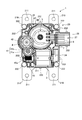
- FIG. 1 is a plan view of a rotating device according to an embodiment.
- FIG. 2 is a bottom view of the rotating device according to the embodiment.
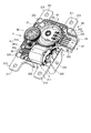
- FIG. 3 is a perspective view of the rotating device according to the embodiment with the first housing removed.
- FIG. 4 is a plan view of the rotating device according to the embodiment with the first housing removed.
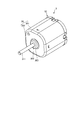
- FIG. 5 is a perspective view of the motor.
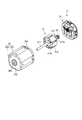
- FIG. 6 is an exploded perspective view of the motor.
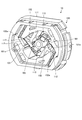
- FIG. 7 is a front view of the bracket as seen from the frame side.
- FIG. 8 is an exploded perspective view of the bracket.
- FIG. 9 is a front view of the bracket as seen from the frame side.
- FIG. 10 is a perspective view of the bracket as seen from the frame side.
- FIG. 11 is a schematic view taken along the line XI-XI of FIG.
- FIG. 12 is a perspective view of a bracket body portion according to a modification.
- FIG. 13 is a perspective view of a bracket according to a modified example.
- FIG. 14 is a front view of a motor according to the modification.
- the motor according to the embodiment is provided in a rotating device.
- FIG. 1 is a plan view of a rotating device 1 according to the embodiment.
- FIG. 2 is a bottom view of the rotating device 1 according to the embodiment.
- FIG. 3 is a perspective view of the rotating device 1 according to the embodiment with the first housing 2A removed.
- FIG. 4 is a plan view of the rotating device 1 according to the embodiment with the first housing 2A removed.
- the rotating device 1 can be suitably used as, for example, an actuator used in an air conditioning system for a vehicle, and can control the rotating operation of a louver for controlling the air volume and the like.
- the rotating device 1 includes a housing 2, a motor 3, a gear group 4 (gear mechanism), and a rotation angle detection sensor 5.
- the housing 2 includes a first housing 2A and a second housing 2B.
- the housing 2 houses the motor 3, the gear group 4, and the rotation angle detection sensor 5.
- the first housing 2A includes a first surface portion 20 serving as a top surface portion of the housing 2 and a first side wall portion 21 provided on an outer peripheral portion of the first surface portion 20.
- An opening (not shown) surrounded by the first side wall 21 is formed in the first housing 2A so as to face the first surface 20.
- the first side wall portion 21 of the first housing 2A is formed with a first insertion portion 22 into which an external connector (not shown) is inserted.
- the second housing 2 ⁇ /b>B includes a second surface portion 23 that serves as a bottom surface portion of the housing 2 and a second side wall portion 24 provided on the outer peripheral portion of the second surface portion 23.
- An opening 25 surrounded by the second side wall 24 is formed in the second housing 2B so as to face the second surface 23.
- the second side wall portion 24 of the second housing 2B is formed with a second insertion portion 26 into which an external connector (not shown) is inserted.
- the housing 2 is configured by connecting the first housing 2A and the second housing 2B in a state where the opening of the first housing 2A and the opening 25 of the second housing 2B are attached to each other. It The first insertion portion 22 and the second insertion portion 26 are connected to each other to form a connector that accommodates an external connector.
- the housing 2 is made of a resin material such as polypropylene, polyethylene terephthalate or ABS.
- a plurality of engaging portions 200 extending to the second casing 2B side are integrally formed on the outer peripheral portion of the first side wall portion 21.
- the engaging portion 200 is provided with an engaging recess 201.
- a plurality of protrusions 202 (hereinafter, referred to as engaging projections 202) corresponding to the plurality of engaging portions 200 of the first housing 2A are provided on the second side wall portion 24. It is formed integrally.
- the engagement protrusion 202 engages with the engagement recess 201 of the engagement portion 200.
- the first housing 2A is provided with the engaging portion 200 and the second housing 2B is provided with the engaging protrusion 202.
- the second housing 2B is provided with the engaging portion.
- An engaging protrusion may be provided on the first housing 2A.
- a piece 210 protruding outward is formed at each end of one side of the first housing 2A and the second housing 2B.
- the joint piece 210 is provided with a connecting hole 211 through which a predetermined tightening tool (not shown) is inserted, and the first housing 2A and the second housing 2B are predetermined through the four connecting holes 211. It is firmly connected by the tightening tool.
- a cylindrical protrusion 221 having a first through hole 220 into which a fastener (not shown) such as a bolt or a screw can be inserted is formed so as to protrude from the first surface portion 20.
- a fastener such as a bolt or a screw
- the second housing 2B is provided with a second through hole 222 into which the protrusion 221 is fitted.
- the motor 3 may be a known motor such as a stepping motor or a brushless motor, but is a DC motor in the illustrated example, and the worm 40 included in the gear group 4 is mounted on the rotary shaft 311 of the motor 3.
- the motor 3 is provided with a connection terminal 8 provided in an insertion port 27 formed by the first insertion portion 22 of the first housing 2A and the second insertion portion 26 of the second housing 2B, and the flexible substrate 7. Power is supplied from the external connector.
- the configuration of the motor 3 will be described later.
- the gear group 4 includes a worm 40, a first transmission gear 41, a second transmission gear 42, and an output gear 43 (rotating body).
- the worm 40 rotates together with the rotating shaft 311 of the motor 3.
- the worm 40 is rotatably supported by the second housing 2B at the top 40a opposite to the motor 3.
- the rotation of the worm 40 is transmitted to the helical gear 41a of the first transmission gear 41, and is transmitted to the second gear via a small diameter gear 41b relatively smaller in diameter than the helical gear 41a, which is coaxial with the helical gear 41a. It is transmitted to the transmission gear 42. Then, the rotation of the second transmission gear 42 is transmitted to the output gear 43. An output shaft 44 is connected to the output gear 43. The rotation of the motor 3 is decelerated at a predetermined reduction ratio and output from the output shaft 44 to the outside.
- the rotation angle detection sensor 5 detects the rotation angle of the output gear 43 in order to control the rotation angle of the output gear 43.
- FIG. 5 is a perspective view of the motor 3.
- FIG. 6 is an exploded perspective view of the motor 3.
- the motor 3 includes a frame 30, a plurality of magnets (not shown), an armature 31, and a bracket 32.
- the frame 30 includes a bottom portion 300 and a tubular portion (hereinafter, referred to as a side wall portion) 301 provided along the peripheral edge of the bottom portion 300.
- a bearing portion 303 is formed on the bottom portion 300 so as to project outward in the rotation axis direction.
- the bearing portion 303 is formed with a hole portion 302 that guides the rotation shaft 311 of the armature 31 (rotation shaft 311 of the motor 3) to the outside.
- a bearing (not shown) that rotatably supports the rotating shaft is provided inside the bearing portion 303.
- the side wall portion 301 is formed so as to cover the outer periphery of the amateur 31.
- An opening 304 is formed in the side wall 301 on the side opposite to the bottom 300.
- the amateur 31 includes a core 310, coils (not shown) wound around a plurality of poles 310a of the core 310, a rotating shaft 311 fixed to the core 310, and a commutator 312.
- the core 310 is configured by stacking a plurality of metal plates along the axial direction of the rotating shaft 311. Examples of the metal plate include electromagnetic steel plates.
- the rotating shaft 311 is arranged in the center of the core 310 so as to penetrate the core 310.
- the commutator 312 is provided on the outer peripheral surface of the rotating shaft 311. Specifically, the commutator 312 is provided along the circumferential direction of the rotating shaft 311.
- the commutator 312 includes a plurality of sheet metals 312a provided on the other end side of the rotating shaft 311 that is located outside the motor 3 and that is located on the opposite side of the one end.
- the end of the coil wound around each pole 310a of the core 310 is connected to the sheet metal 312a by solder or the like.
- the end of the rotating shaft 311 on the commutator 312 side is rotatably supported by the bearing 33.
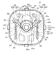
- FIG. 7 is a front view of the bracket 32 seen from the frame 30 side.
- FIG. 8 is an exploded perspective view of the bracket 32.
- the bracket 32 includes a bearing plate 320, a bracket body portion (hereinafter, referred to as a body portion) 321, a pair of terminal portions 322, a pair of brushes 323, and a pair of deforming portions 324.
- a plate (hereinafter referred to as a bearing plate) 320 is attached to the main body 321 from the side opposite to the frame 30 (see FIGS. 5 and 6).
- a bearing portion 320a is formed in the center of the bearing plate 320.
- the bearing portion 320a is recessed toward the side opposite to the main body portion 321, and the bearing 33 is accommodated therein.
- the bearing plate 320 is formed with a pair of holes (hereinafter, referred to as insertion holes) 320b sandwiching the bearing 320a.
- the end portion 340a of the terminal portion 322 is inserted into the insertion hole 320b.
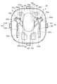
- FIG. 9 is a front view of the main body 321 viewed from the frame 30 side.
- FIG. 10 is a perspective view of the main body 321 viewed from the frame 30 side.
- the main body 321 is configured to be thick along the axial direction of the rotating shaft 311 (see FIG. 6).
- the body portion 321 accommodates a hole portion (hereinafter referred to as an insertion hole) 330 in which a commutator 312 (see FIG. 6) is arranged, a terminal portion 322, a part of the brush 323, and a deformable portion 324.
- a pair of accommodating portions 331 are formed.
- the insertion hole 330 has an oval shape and is formed along the axial direction of the rotating shaft 311.
- the commutator 312 is inserted into the insertion hole 330 together with the rotating shaft 311.
- the accommodating portion 331 is recessed from the top surface (hereinafter, referred to as a front wall) 321 a on the core 310 side along the axial direction of the rotating shaft 311, specifically, from the front wall 321 a toward the bearing plate 320 side. Is formed so that The accommodating portion 331 is formed by the first accommodating portion 332 and the second accommodating portion 333 so as to have a T shape when viewed from the core 310 side.
- the first accommodating portion 332 is formed along the longitudinal direction of the oval insertion hole 330.
- a hole portion (hereinafter referred to as an insertion hole) 332b into which the end portion 340a of the terminal portion 322 is inserted is formed in the bottom portion 332a of the first accommodating portion 332.
- the second accommodating portion 333 is formed so as to intersect the first accommodating portion 332, and one end of the first accommodating portion 332 is connected to the first side wall surface 333a (second wall surface). That is, the first accommodation portion 332 and the second accommodation portion 333 communicate with each other.
- An opening 334 is formed at an end of the second storage portion 333 on the commutator 312 side so that the second storage portion 333 and the insertion hole 330 communicate with each other.
- the opening 334 is open on the side of the bearing plate 320 and the side of the armature 31.
- the opening 334 is part of the openings of the first housing 332 and the second housing 333, and part of these openings is open to the armature 31 side.
- the second accommodating portion 333 has a recess 335 formed in a second side wall surface 333b (first wall surface) that faces the first side wall surface 333a.
- a third side wall surface 333c that faces the insertion hole 330 or the space S in the second storage portion 333 is formed in the second storage portion 333, and the first side wall surface 333a and the second side wall surface 333b are the third side wall surface 333a. It is connected by the side wall surface 333c.
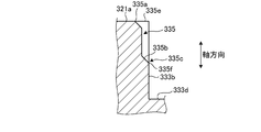
- the recess 335 has an opening that forms a part of the opening 334 at one end 335e in the axial direction of the rotation shaft 311 of the motor 3, specifically, at the end 335e on the front wall 321a side.
- the part 335a is formed. That is, in the axial direction of the rotating shaft 311, the recess 335 has two ends 335e and 335f, one end 335e forms the opening 335a, and the other end 335f has the inclined surface 335b.
- the one end 335e is an end on the front wall 321a side, and the other end 335f is an end on the bottom 333d side of the second accommodating portion 333.
- the recess 335 is formed up to the intermediate portion 335c of the second side wall surface 333b in the axial direction of the rotating shaft 311. That is, the recess 335 is formed along the axial direction of the rotary shaft 311 from the front wall 321a, and the end portion 335f on the side opposite to the front wall 321a is closer to the front wall 321a side than the bottom portion 333d of the second accommodating portion 333. And is formed in the intermediate portion 335c of the second side wall surface 333b (a part of the wall surface) in the axial direction of the rotating shaft 311.
- an inclined surface 335b is formed at the end 335f on the side opposite to the front wall 321a.
- the inclined surface 335b is formed such that the distance from the opening 335a becomes longer in the axial direction of the rotation shaft 311 as it approaches the second accommodation portion 333 side.
- the main body 321 includes a first protrusion 336 and a second protrusion 337, as shown in FIGS. 8 to 10.
- the first protruding portion 336 and the second protruding portion 337 are formed at the end of the second accommodating portion 333 on the commutator 312 side.
- the first protrusion 336 and the second protrusion 337 are formed so as to face each other.
- the first protrusion 336 and the second protrusion 337 form a part of the space S of the second accommodating portion 333 or the opening 334.
- the first protruding portion 336 is provided closer to the commutator 312 side than the first resin portion 350a of the first deforming portion 350 that constitutes the deforming portion 324 by protruding from the second side wall surface 333b toward the brush 323.
- the second projecting portion 337 is provided on the commutator 312 side rather than the end portion on the commutator 312 side of the second deforming portion 351 that constitutes the deforming portion 324 and projects from the first side wall surface 333 a toward the brush 323.
- the first protruding portion 336 and the second protruding portion 337 are in contact with the end portion of the deforming portion 324 on the commutator 312 side in the radial direction.
- the terminal portion 322 has one end 340 and the other end 341. Further, the terminal portion 322 has a bent portion 342 formed between the one end portion 340 and the other end portion 341. The terminal portion 322 is formed into a bent shape by bending an L-shaped metal plate.
- the one end 340 is housed in the first housing 332 of the main body 321.
- the end portion 340a of the one end portion 340 opposite to the core 310 is inserted into the insertion hole 332b (see FIG. 9) of the first accommodating portion 332 and the insertion hole 320b of the bearing plate 320. It projects from 320.
- One end portion 340 protruding from the bearing plate 320 is electrically connected to the external connector via the flexible substrate 7 (see FIG. 3) and the connection terminal 8 (see FIG. 3).
- the other end 341 is housed in the second housing 333 of the main body 321.
- the other end portion 341 is formed so as to extend toward the opposite side of the one end portion 340 from the insertion hole 330 of the body portion 321, that is, toward the radially outer side of the rotating shaft 311.
- the brush 323 is attached to the other end 341.
- the brush 323 is a deformable plate and has conductivity.
- the brush 323 contacts the commutator 312 at the contact surface 323a.
- the brush 323 is attached to the other end 341 of the terminal portion 322.
- a lubricant is present between the contact surface 323a and the commutator 312. This lubricant is provided as a separate member with respect to the above-mentioned first resin portion 350a, and a known lubricant can be used.
- the deformation unit 324 is housed in the second housing unit 333.
- the deforming section 324 includes a first deforming section 350, a second deforming section 351, and a third deforming section 352.
- the deforming portion 324 has a restoring force and has a function of suppressing vibration of the brush 323.
- the first deforming portion 350 is provided between the brush 323 and the second side wall surface 333b (first wall surface) of the second accommodating portion 333 that faces the brush 323. Specifically, the first deforming portion 350 is provided between the second side wall surface 333b and the surface of the brush 323 that contacts the commutator 312.
- the first deformable portion 350 includes a first resin portion 350a and a second resin portion 350b.
- the first resin portion 350a is made of gel.
- the gel is, for example, a two-component curing type, an ultraviolet curing type, or a thermosetting type.
- the gel is injected by inserting a nozzle (not shown) of a dispenser into a recess 335 formed in the second side wall surface 333b of the second storage portion 333.
- the first resin portion 350a contacts the second side wall surface 333b.
- the first resin portion 350a is prevented from moving toward the commutator 312 side by the first protruding portion 336. That is, the first protruding portion 336 functions as a stopper that suppresses the outflow of the first resin portion 350a to the commutator 312 side.
- the second resin portion 350b has a flat plate shape and is made of, for example, rubber as an elastic member having elasticity.
- the second resin portion 350b is harder than the first resin portion 350a.
- the second resin portion 350b is provided between the brush 323 and the first resin portion 350a.
- the second resin portion 350b is fixed to the brush 323.
- the end of the second resin portion 350b on the commutator 312 side projects toward the commutator 312 side of the end of the first resin portion 350a on the commutator 312 side, and the end of the first resin portion 350a on the commutator 312 side extends. Support the edges.
- the end of the first resin part 350a on the commutator 312 side is moved to the commutator 312 side by the first protrusion 336 while being supported by the second resin part 350b and being suppressed from being deformed to the brush 323 side. Are prevented from moving.
- the second deforming portion 351 is provided closer to the commutator 312 side than the terminal portion 322, and is provided between the first side wall surface 333 a (second wall surface) of the second accommodating portion 333 and the brush 323. Specifically, the second deformable portion 351 is provided between the first side wall surface 333a and the surface 323b on the opposite side of the contact surface 323a of the brush 323 that contacts the commutator 312.
- the second deformable portion 351 is made of gel.
- the second deformable portion 351 is composed of a member that is more easily deformed than the first deformable portion 350.
- the end of the second deformable portion 351 is in contact with the second protruding portion 337 of the main body portion 321, and the movement toward the commutator 312 side is suppressed by the second protruding portion 337. That is, the second projecting portion 337 functions as a stopper that suppresses the outflow of the second deforming portion 351 to the commutator 312 side.
- the second deformable portion 351 is provided such that the end portion of the second deformable portion 351 on the commutator 312 side is located closer to the commutator 312 side than the end portion of the first deformable portion 350 on the commutator 312 side.
- the second protrusion 337 is located closer to the commutator 312 than the end of the first deformable portion 350 on the commutator 312 side.
- the second deformable portion 351 supports the commutator 312 side end of the first deformable portion 350 with the brush 323 interposed therebetween.
- the third deformable portion 352 is provided on the opposite side of the second deformable portion 351 with respect to the terminal portion 322 in the radial direction. Specifically, the third deformable portion 352 is provided between the terminal portion 322 and the first side wall surface 333a of the second accommodating portion 333. Therefore, the terminal portion 322 is arranged as a partition member that partitions the third deformable portion 352 and the second deformable portion 351. Further, the end of the third deformable portion 352 on the side opposite to the commutator 312 extends toward the first deformable portion 350 between the terminal portion 322 and the third side wall surface 333c of the second accommodating portion 333. It is provided.
- the third deforming portion 352 is formed along the first side wall surface 333a and the third side wall surface 333c of the second accommodating portion 333.
- the third deforming portion 352 is provided so as to surround the brush 323 and the terminal portion 322 located on the opposite side of the commutator 312.
- the third deforming portion 352 is made of gel.
- the third deformable portion 352 may have the same member as the first resin portion 350a of the first deformable portion 350 or the second deformable portion 351, or may be made of a different member.
- the third deformable portion 352 may be configured integrally with the first resin portion 350a of the first deformable portion 350. Further, the gel forming the second deformable portion 351 and the third deformable portion 352 may be injected from the recess 335 by a dispenser like the first resin portion 350a of the first deformable portion 350.
- the motor 3 accommodates the brush 323 that contacts the commutator 312 in the housing 331 formed in the main body 321, and includes the deforming portion 324 that contacts the first sidewall surface 333a to the third sidewall 333c of the housing 331. ..
- the main body portion 321 is provided with a first protruding portion 336 and a second protruding portion 337 that protrude toward the brush 323, closer to the commutator 312 side than the deforming portion 324.
- the main body 321 includes a first protrusion 336 protruding from the first side wall surface 333a toward the brush 323, and a second protrusion 337 protruding from the second side wall surface 333b toward the brush 323. Is provided.
- the deforming portion 324 on the commutator 312 side specifically, the first resin portion 350a of the first deforming portion 350 contacts the first protruding portion 336, and the end portion of the second deforming portion 351 protrudes to the second protruding portion 336. Contact the portion 337. Therefore, the motor 3 can suppress the deformation portion 324 from flowing out to the commutator 312 side, and can prevent the deformation portion 324 from flowing out to the contact portion between the commutator 312 and the brush 323. Therefore, the motor 3 can improve the electrical contact between the brush 323 and the commutator 312.
- the motor 3 can reduce the vibration of the brush 323 and improve the noise reduction by providing the deforming portion 324.
- a recess 335 is formed in the second side wall surface 333b that is a part of the wall surface that contacts the deformable portion 324.
- an opening 335a is formed at one end 335e in the axial direction of the rotary shaft 311 of the motor 3.
- the nozzle of the dispenser can be inserted into the recess 335 and the gel can be supplied to the second storage portion 333, the contact of the nozzle of the dispenser with the brush 323 can be suppressed, and the deformation of the brush 323 can be suppressed. can do.
- one end 335e of the recess 335 forms an opening 335a
- the other end 335f of the recess 335 forms an inclined surface 335b.
- the gel when the gel is supplied from the nozzle of the dispenser, the gel can be made to flow toward the second accommodating portion 333, and the overflow of the gel from the recess 335 can be suppressed.
- the other end 335f of the recess 335 is located in the intermediate portion 335c which is a part of the second side wall surface 333b in the axial direction of the rotary shaft 311. That is, the recess 335 is not formed up to the bottom portion 333d of the second accommodation portion 333.
- the gel supplied from the nozzle of the dispenser can flow from the intermediate portion 335c toward the bottom portion 333d of the second storage portion 333, and the gel supplied from the nozzle of the dispenser directly collides with the bottom portion 333d. It is possible to prevent the gel from overflowing from the second containing portion 333.
- first deformable portion 350 is provided between the first resin portion 350a that contacts the second side wall surface 333b and the brush 323 and the first resin portion 350a, and the second resin that is harder than the first resin portion 350a.
- the first protrusion 336 is located closer to the commutator 312 than the end of the first resin portion 350a on the commutator 312 side.
- the commutator 312 side end of the second resin portion 350b is located closer to the commutator 312 side than the commutator 312 side end of the first resin portion 350a.
- the commutator 312 side end of the first resin part 350a is supported by the second resin part 350b, so that the commutator 312 side end of the first resin part 350a becomes the second resin part 350b side.
- the motor 3 can prevent the first resin portion 350a from flowing out to the commutator 312 side, and can improve the electrical contact between the brush 323 and the commutator 312.
- the second protruding portion 337 is located closer to the commutator 312 than the end portion of the first deformable portion 350 on the commutator 312 side.
- the end portion of the first deforming portion 350 on the commutator 312 side is supported by the second deforming portion 351 with the brush 323 interposed therebetween. Therefore, the end of the first deformable portion 350 on the commutator 312 side can be suppressed from moving to the second deformable portion 351 side. Therefore, the motor 3 can prevent the first resin portion 350a from flowing out to the commutator 312 side, and can improve the electrical contact between the brush 323 and the commutator 312.
- the second deformable portion 351 is provided between the first side wall surface 333 a and the surface 323 b on the opposite side of the contact surface 323 a of the brush 323 that comes into contact with the commutator 312, and more than the first deformable portion 350. Easy to deform.
- the motor 3 suppresses an increase in the force that presses the brush 323 toward the commutator 312, reduces the contact resistance between the brush 323 and the commutator 312, and suppresses the vibration of the brush 323. it can.
- the third deforming portion 352 is formed so as to surround the end portion of the brush 323 on the side opposite to the commutator 312.
- the motor 3 can suppress the vibration of the brush 323 from being transmitted to the main body portion 321, and can improve the quietness.
- the deformation unit 324 has a restoring force.
- the motor 3 can suppress the vibration of the brush 323, and can improve the quietness.
- the deforming portion 324 is formed so as to contact the other end portion 341 of the terminal portion 322 and the first side wall surface 333a to the third side wall surface 333c of the second accommodating portion 333.
- the motor 3 can suppress the vibration of the brush 323 from being transmitted to the main body portion 321 via the terminal portion 322, and can improve the quietness.
- the bracket main body 321 (main body 321) of the motor 10 may be the bracket main body 3210 (hereinafter, main body 3210) shown in FIGS. 12 and 13.
- FIG. 12 is a perspective view of a bracket main body 3210 according to a modification
- FIG. 13 is a perspective view of a bracket 3200 according to the modification.
- parts of the main body 321 and the bracket 32 which are different from the main body 3210 and the bracket 3200 according to the modified example will be described, and the same parts will be denoted by the same reference numerals and description thereof will be appropriately omitted. To do.
- the bracket 3200 includes a bearing plate 320, a pair of terminal portions 322, a pair of brushes 323, and a pair of deforming portions 324.
- the bracket 3200 includes a main body 3210 instead of the main body 321, and further includes a pair of resin portions 400.
- the body portion 3210 is formed with an insertion hole 330 in which a commutator 312 (see FIG. 6) is arranged, and a pair of housing portions 331 for housing the terminal portion 322, a part of the brush 323, and the deformable portion 324. .. Further, the main body portion 3210 is formed with a pair of storage portions 410 that store a pair of resin portions 400.
- the accommodation section 331 is formed by a first accommodation section 332 and a second accommodation section 333.
- the deforming section 324 is housed in the second housing section 333.
- the deforming section 324 includes a first deforming section 350, a second deforming section 351, and a third deforming section 352.
- the first deformable portion 350 includes a first resin portion 350a and a second resin portion 350b.
- the deforming portion 324 has a restoring force and has a function of suppressing vibration of the brush 323.
- the main body 3210 includes a first protrusion 336 and a second protrusion 337.
- the first protruding portion 336 and the second protruding portion 337 are formed at the end of the second accommodating portion 333 on the commutator 312 side.
- the first protrusion 336 and the second protrusion 337 are formed so as to face each other.
- the first projecting portion 336 functions as a stopper that suppresses the outflow of the first resin portion 350a toward the commutator 312 side.
- the second projecting portion 337 functions as a stopper that suppresses the outflow of the second deforming portion 351 to the commutator 312 side.
- the second side wall surface 333b of the second accommodating portion 333 is formed with a concave portion (hereinafter referred to as a storage portion) 410 that is recessed in a direction away from the first side wall surface 333a.
- the storage part 410 includes a slit-shaped communication part 410a formed on the second side wall surface 333b so as to communicate with the second storage part 333, and a cylindrical third storage part 410b connected to the communication part 410a.
- the communication part is a road or a passage.
- the resin part 400 stored in the storage part 410 is made of the same gel as the first resin part 350a.
- the gel is injected by inserting a nozzle (not shown) of a dispenser into the third container 410b.
- the third accommodating portion 410b and the communication portion 410a are filled with the gel, and the resin portion 400 is formed.
- the gel further flows into the second accommodating portion 333, and the first resin portion 350a is formed.
- the resin part 400 functions as a supply source that prevents the gel constituting the first resin part 350a from being depleted.
- the resin portion 400 can damp the vibration of the brush 323 that the first resin portion 350a could not damp. Therefore, the bracket 3200 according to the modified example can reliably suppress the vibration of the brush 323 from being transmitted to the main body portion 3210 via the terminal portion 322, and can improve the quietness.
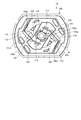
- the motor 10 may be a motor using a pair of carbon brushes 113, as shown in FIGS. 14 to 16.
- FIG. 14 is a front view of the motor 10 according to the modification.
- FIG. 15 is a perspective view of the motor 10 according to the modification.
- 16 is a sectional view taken along line XIV-XIV of FIG.
- the main body 100 of the motor 10 according to the modified example includes a first protrusion 101 that protrudes toward the brush 113 and a second protrusion 102. Further, the motor main body 100 according to the modification has a bottom portion 103a (bottom surface) that connects the first side wall surface 101a from which the first protruding portion 101 protrudes and the second side wall surface 102a from which the second protruding portion 102 protrudes.
- the third protrusion 103 protruding toward the brush 113 is provided.
- the third protruding portion 103 is formed at the end of the second accommodating portion 110 on the commutator 111 side.
- the first protruding portion 101 to the third protruding portion 103 are continuously formed. That is, the third protrusion 103 is formed so as to connect the first protrusion 101 and the second protrusion 102.
- the bottom portion 103a is an inclined surface that is inclined so that the height becomes higher toward the third protruding portion 103 side. That is, the bottom portion 103a is formed to have a downward slope from the third protruding portion 103 side.
- the motor 100 according to the modification can suppress the deformation portion 112 from flowing out to the commutator 111 side by the third protrusion 103. Therefore, the motor 100 according to the modification can improve the electrical contact between the brush 113 and the commutator 111.
- the motor 100 according to the modification includes a bottom portion 103a whose height increases toward the third protruding portion 103 side. Thereby, the motor 100 according to the modification can further suppress the deformation portion 112 from flowing out to the commutator 111 side. Therefore, the motor 100 according to the modification can further improve the electrical contact between the brush 113 and the commutator 111.
- the third protrusion may be provided in the motor 3 according to the above-described embodiment.
- the present invention is not limited to the above embodiment.
- the present invention also includes those configured by appropriately combining the above-described components. Further, further effects and modified examples can be easily derived by those skilled in the art. Therefore, the broader aspects of the present invention are not limited to the above embodiments, and various modifications can be made.
Landscapes
- Engineering & Computer Science (AREA)
- Power Engineering (AREA)
- Motor Or Generator Frames (AREA)
- Motor Or Generator Current Collectors (AREA)
Abstract
Description
Claims (16)
- 回転軸に設けられた整流子と、
前記整流子に接触するブラシと、
前記ブラシに対向する壁面を有するブラケットと、
前記ブラシと前記壁面とに接触する変形部と、
を備え、
前記ブラケットは、
前記変形部よりも前記整流子側に設けられた突出部
を備え、
前記突出部は、前記壁面から前記ブラシに向けて突出しているモータ。 - 径方向において、前記突出部は、前記整流子側における前記変形部の端部に接触する
請求項1に記載のモータ。 - 前記変形部に接触する壁面の一部分には凹部が設けられている
請求項1または2に記載のモータ。 - 前記回転軸の軸方向における前記凹部が有する2つの端部のうち、一方の端部は前記ブラケットの開口部を形成し、他方の端部は傾斜面を形成している
請求項3に記載のモータ。 - 前記凹部の他方の端部は、
前記回転軸の軸方向において、前記壁面の一部分の中間部にある
請求項3または4に記載のモータ。 - 前記変形部は、
前記壁面に接触する第1樹脂部と、
前記ブラシと前記第1樹脂部との間に設けられ、前記第1樹脂部よりも硬い第2樹脂部と
を備え、
前記第2樹脂部の前記整流子側の端部は、前記第1樹脂部の前記整流子側の端部よりも前記整流子側に位置し、
前記突出部は、前記第1樹脂部の前記整流子側の端部よりも前記整流子側に位置する
請求項1~5のいずれか一つに記載のモータ。 - 前記変形部は、
前記ブラシに対向する前記ブラケットの第1壁面と、前記ブラシとの間に設けられる第1変形部と、
前記第1壁面に対向する前記ブラケットの第2壁面と、前記ブラシとの間に設けられた第2変形部と
を備え、
前記ブラケットは、
前記第1壁面から前記ブラシに向けて突出し、前記第1変形部よりも前記整流子側に設けられた第1突出部と、
前記第2壁面から前記ブラシに向けて突出し、前記第2変形部よりも前記整流子側に設けられた第2突出部と
を備える請求項1~6のいずれか一つに記載のモータ。 - 前記第2突出部は、
前記第1変形部の前記整流子側の端部よりも前記整流子側に位置する
請求項7に記載のモータ。 - 前記第2変形部は、
前記第2壁面と、前記整流子に接触する前記ブラシの接触面とは反対側の面との間に設けられ、かつ前記第1変形部よりも変形し易い
請求項7または8に記載のモータ。 - 前記変形部は、
前記整流子とは反対側の前記ブラシの端部を囲んでいる
請求項1~9のいずれか一つに記載のモータ。 - 前記変形部は、復元力を有する
請求項1~10のいずれか一つに記載のモータ。 - 一端部と、前記ブラシが取り付けられる他端部と、前記一端部と前記他端部との間に形成された屈曲部とを有する端子部
を備え、
前記ブラケットは、
前記端子部を収容し、前記壁面を有する収容部
を備え、
前記変形部は、
前記他端部と前記壁面とに接触する
請求項1~11のいずれか一つに記載のモータ。 - 前記ブラケットは、
前記ブラシに対向する2つの壁面を接続する底面を有し、
前記突出部は、
前記壁面、および前記底面から前記ブラシに向けて突出している
請求項1に記載のモータ。 - 前記底面は、
前記突出部側の高さが高くなるように傾斜した傾斜面である
請求項13に記載のモータ。 - 前記ブラシと前記整流子との間には、樹脂部に対して別部材としての潤滑剤が設けられる
請求項1~14のいずれか一つに記載のモータ。 - 請求項1~15のいずれか一つに記載のモータと、
前記回転軸に取り付けられるウォームと、
前記ウォームに噛み合うギアと、
を備える回転機器。
Priority Applications (4)
| Application Number | Priority Date | Filing Date | Title |
|---|---|---|---|
| CN201980087865.7A CN113261185B (zh) | 2019-01-16 | 2019-10-10 | 马达以及旋转设备 |
| DE112019006158.5T DE112019006158T5 (de) | 2019-01-16 | 2019-10-10 | Motor und rotationsmaschine |
| US17/421,928 US11722030B2 (en) | 2019-01-16 | 2019-10-10 | Motor and rotating device |
| JP2020566103A JP7399888B2 (ja) | 2019-01-16 | 2019-10-10 | モータ、および回転機器 |
Applications Claiming Priority (2)
| Application Number | Priority Date | Filing Date | Title |
|---|---|---|---|
| JP2019005211 | 2019-01-16 | ||
| JP2019-005211 | 2019-01-16 |
Publications (1)
| Publication Number | Publication Date |
|---|---|
| WO2020148952A1 true WO2020148952A1 (ja) | 2020-07-23 |
Family
ID=71614518
Family Applications (1)
| Application Number | Title | Priority Date | Filing Date |
|---|---|---|---|
| PCT/JP2019/040053 Ceased WO2020148952A1 (ja) | 2019-01-16 | 2019-10-10 | モータ、および回転機器 |
Country Status (5)
| Country | Link |
|---|---|
| US (1) | US11722030B2 (ja) |
| JP (1) | JP7399888B2 (ja) |
| CN (1) | CN113261185B (ja) |
| DE (1) | DE112019006158T5 (ja) |
| WO (1) | WO2020148952A1 (ja) |
Families Citing this family (2)
| Publication number | Priority date | Publication date | Assignee | Title |
|---|---|---|---|---|
| JP7239328B2 (ja) * | 2019-01-16 | 2023-03-14 | ミネベアミツミ株式会社 | ウォーム、および回転機器 |
| CN111853474B (zh) * | 2019-04-25 | 2022-02-08 | 三星电子株式会社 | 显示装置 |
Citations (8)
| Publication number | Priority date | Publication date | Assignee | Title |
|---|---|---|---|---|
| JPH06165443A (ja) * | 1992-11-18 | 1994-06-10 | Sanyo Electric Co Ltd | 電動機 |
| US5949173A (en) * | 1993-06-07 | 1999-09-07 | General Electric Company | Permanent magnet direct current motor |
| JP2002051509A (ja) * | 2000-08-01 | 2002-02-15 | Asmo Co Ltd | 直流電動機におけるブラシ保持装置及び直流電動機の組立方法 |
| JP2008022619A (ja) * | 2006-07-12 | 2008-01-31 | Nidec Sankyo Corp | ブラシ付きモータ |
| JP2009071925A (ja) * | 2007-09-11 | 2009-04-02 | Denso Corp | 整流子電動機 |
| JP2016127733A (ja) * | 2015-01-06 | 2016-07-11 | 株式会社豊田自動織機 | スリップリング装置及びスリップリング装置を備える回転電機を搭載する車両の車両制御装置 |
| JP2017073918A (ja) * | 2015-10-08 | 2017-04-13 | ミネベアミツミ株式会社 | ブラシ付dcモータ |
| JP2017073950A (ja) * | 2015-10-09 | 2017-04-13 | ミネベアミツミ株式会社 | ブラシ付dcモータ及びブラシ付dcモータの製造方法 |
Family Cites Families (13)
| Publication number | Priority date | Publication date | Assignee | Title |
|---|---|---|---|---|
| US2555997A (en) * | 1942-06-03 | 1951-06-05 | Lorraine Carbone | Sliding contact of electric machines |
| US3955113A (en) * | 1974-11-27 | 1976-05-04 | General Signal Corporation | Brush holder with means for limiting travel of brush spring |
| JPH09182384A (ja) * | 1995-12-27 | 1997-07-11 | Makita Corp | モータのブラシ摩耗報知装置 |
| JP2006050832A (ja) * | 2004-08-06 | 2006-02-16 | Tokyo Parts Ind Co Ltd | モータ |
| DE202006003747U1 (de) * | 2006-03-06 | 2007-07-12 | Brose Fahrzeugteile Gmbh & Co. Kommanditgesellschaft, Coburg | Bürstenträger für Kontaktbürsten einer Kommutatormaschine |
| JP5006713B2 (ja) * | 2007-06-28 | 2012-08-22 | 株式会社ミツバ | ブラシ付き電動モータ |
| JP2011244629A (ja) * | 2010-05-20 | 2011-12-01 | C I Kasei Co Ltd | 耐衝撃性を有する直流モータ |
| JP2013005632A (ja) * | 2011-06-17 | 2013-01-07 | Asmo Co Ltd | ブラシユニット及び直流モータ |
| CN102957288B (zh) * | 2011-08-10 | 2017-12-12 | 德昌电机(深圳)有限公司 | 驱动装置及其有刷电机 |
| JP6528501B2 (ja) * | 2015-03-26 | 2019-06-12 | 日本電産株式会社 | モータおよびファン |
| JP6425254B2 (ja) * | 2016-09-02 | 2018-11-21 | ミネベアミツミ株式会社 | モータ |
| CN107834737A (zh) * | 2017-12-14 | 2018-03-23 | 四川安和精密电子电器有限公司 | 一种振动组件和线性振动马达 |
| JP6580754B2 (ja) * | 2018-06-05 | 2019-09-25 | ミネベアミツミ株式会社 | モータ |
-
2019
- 2019-10-10 JP JP2020566103A patent/JP7399888B2/ja active Active
- 2019-10-10 CN CN201980087865.7A patent/CN113261185B/zh active Active
- 2019-10-10 DE DE112019006158.5T patent/DE112019006158T5/de active Pending
- 2019-10-10 US US17/421,928 patent/US11722030B2/en active Active
- 2019-10-10 WO PCT/JP2019/040053 patent/WO2020148952A1/ja not_active Ceased
Patent Citations (8)
| Publication number | Priority date | Publication date | Assignee | Title |
|---|---|---|---|---|
| JPH06165443A (ja) * | 1992-11-18 | 1994-06-10 | Sanyo Electric Co Ltd | 電動機 |
| US5949173A (en) * | 1993-06-07 | 1999-09-07 | General Electric Company | Permanent magnet direct current motor |
| JP2002051509A (ja) * | 2000-08-01 | 2002-02-15 | Asmo Co Ltd | 直流電動機におけるブラシ保持装置及び直流電動機の組立方法 |
| JP2008022619A (ja) * | 2006-07-12 | 2008-01-31 | Nidec Sankyo Corp | ブラシ付きモータ |
| JP2009071925A (ja) * | 2007-09-11 | 2009-04-02 | Denso Corp | 整流子電動機 |
| JP2016127733A (ja) * | 2015-01-06 | 2016-07-11 | 株式会社豊田自動織機 | スリップリング装置及びスリップリング装置を備える回転電機を搭載する車両の車両制御装置 |
| JP2017073918A (ja) * | 2015-10-08 | 2017-04-13 | ミネベアミツミ株式会社 | ブラシ付dcモータ |
| JP2017073950A (ja) * | 2015-10-09 | 2017-04-13 | ミネベアミツミ株式会社 | ブラシ付dcモータ及びブラシ付dcモータの製造方法 |
Also Published As
| Publication number | Publication date |
|---|---|
| US20220109343A1 (en) | 2022-04-07 |
| DE112019006158T5 (de) | 2021-09-02 |
| CN113261185B (zh) | 2025-04-18 |
| JP7399888B2 (ja) | 2023-12-18 |
| JPWO2020148952A1 (ja) | 2021-12-02 |
| US11722030B2 (en) | 2023-08-08 |
| CN113261185A (zh) | 2021-08-13 |
Similar Documents
| Publication | Publication Date | Title |
|---|---|---|
| JP3639211B2 (ja) | モータ | |
| JP2011114979A (ja) | モータ、このモータを用いたポンプ及びこのポンプを用いた液体循環装置 | |
| JP2000324766A (ja) | 整流子モータ | |
| US11462969B2 (en) | Rotary apparatus | |
| JP7399888B2 (ja) | モータ、および回転機器 | |
| JP2023068175A (ja) | ロータ、モータ、及びワイパモータ | |
| JP2002044904A (ja) | 小型モータ | |
| US6495939B1 (en) | Coreless motor having tubular housing with end mounting portions | |
| JP3773853B2 (ja) | ブラシホルダ及び電動モータ | |
| JP3393400B2 (ja) | モータのロータ予圧装置 | |
| JP5848076B2 (ja) | モータ | |
| JP7418945B2 (ja) | 回転装置 | |
| JP2017208945A (ja) | 直流モータ | |
| JP2021061653A (ja) | モータ装置 | |
| JP2020005487A (ja) | モータ | |
| JP2020171081A (ja) | モータ装置 | |
| WO2023276678A1 (ja) | 駆動装置 | |
| JP2006211857A (ja) | 小型モータ | |
| JP2005348538A (ja) | モータ | |
| CN112930455B (zh) | 阀驱动装置 | |
| JP5848108B2 (ja) | モータ | |
| JP4417803B2 (ja) | モータ | |
| JP2002078284A (ja) | モータ | |
| JP4659471B2 (ja) | 電動駆動装置 | |
| WO2019244873A1 (ja) | モータ |
Legal Events
| Date | Code | Title | Description |
|---|---|---|---|
| 121 | Ep: the epo has been informed by wipo that ep was designated in this application |
Ref document number: 19910613 Country of ref document: EP Kind code of ref document: A1 |
|
| ENP | Entry into the national phase |
Ref document number: 2020566103 Country of ref document: JP Kind code of ref document: A |
|
| 122 | Ep: pct application non-entry in european phase |
Ref document number: 19910613 Country of ref document: EP Kind code of ref document: A1 |
|
| WWG | Wipo information: grant in national office |
Ref document number: 201980087865.7 Country of ref document: CN |