WO2020145264A1 - ソケット装置 - Google Patents
ソケット装置 Download PDFInfo
- Publication number
- WO2020145264A1 WO2020145264A1 PCT/JP2020/000155 JP2020000155W WO2020145264A1 WO 2020145264 A1 WO2020145264 A1 WO 2020145264A1 JP 2020000155 W JP2020000155 W JP 2020000155W WO 2020145264 A1 WO2020145264 A1 WO 2020145264A1
- Authority
- WO
- WIPO (PCT)
- Prior art keywords
- stopper
- cylindrical body
- leg
- cylinder
- socket device
- Prior art date
- Legal status (The legal status is an assumption and is not a legal conclusion. Google has not performed a legal analysis and makes no representation as to the accuracy of the status listed.)
- Ceased
Links
Images








Classifications
-
- F—MECHANICAL ENGINEERING; LIGHTING; HEATING; WEAPONS; BLASTING
- F16—ENGINEERING ELEMENTS AND UNITS; GENERAL MEASURES FOR PRODUCING AND MAINTAINING EFFECTIVE FUNCTIONING OF MACHINES OR INSTALLATIONS; THERMAL INSULATION IN GENERAL
- F16L—PIPES; JOINTS OR FITTINGS FOR PIPES; SUPPORTS FOR PIPES, CABLES OR PROTECTIVE TUBING; MEANS FOR THERMAL INSULATION IN GENERAL
- F16L37/00—Couplings of the quick-acting type
- F16L37/08—Couplings of the quick-acting type in which the connection between abutting or axially overlapping ends is maintained by locking members
- F16L37/084—Couplings of the quick-acting type in which the connection between abutting or axially overlapping ends is maintained by locking members combined with automatic locking
- F16L37/086—Couplings of the quick-acting type in which the connection between abutting or axially overlapping ends is maintained by locking members combined with automatic locking by means of latching members pushed radially by spring-like elements
-
- F—MECHANICAL ENGINEERING; LIGHTING; HEATING; WEAPONS; BLASTING
- F16—ENGINEERING ELEMENTS AND UNITS; GENERAL MEASURES FOR PRODUCING AND MAINTAINING EFFECTIVE FUNCTIONING OF MACHINES OR INSTALLATIONS; THERMAL INSULATION IN GENERAL
- F16L—PIPES; JOINTS OR FITTINGS FOR PIPES; SUPPORTS FOR PIPES, CABLES OR PROTECTIVE TUBING; MEANS FOR THERMAL INSULATION IN GENERAL
- F16L37/00—Couplings of the quick-acting type
- F16L37/08—Couplings of the quick-acting type in which the connection between abutting or axially overlapping ends is maintained by locking members
- F16L37/12—Couplings of the quick-acting type in which the connection between abutting or axially overlapping ends is maintained by locking members using hooks, pawls, or other movable or insertable locking members
- F16L37/14—Joints secured by inserting between mating surfaces an element, e.g. a piece of wire, a pin, a chain
Definitions
- the present invention relates to improvement of a socket device.
- Patent Document 1 Regarding the quick connector assembly, there is one disclosed in Patent Document 1.
- the thing of this patent document 1 has a female-type connecting member which has the accommodation part of a male-type connecting member.
- the female connecting member is combined with a holding device composed of a wire partially inserted into the female connecting member through the through slot.
- a male connecting member when a male connecting member is inserted into the accommodating portion, a part of the holding device is engaged with the male connecting member, whereby both members are connected. ing.
- the main problem to be solved by the present invention is that in this type of socket device or connector assembly, the engagement state of the stopper with respect to the connecting object can be maintained as stable as possible.
- a socket device An inner cylinder, An outer cylinder, With a stopper made of metal wire
- the inner cylindrical body has split grooves on both sides sandwiching the cylindrical axis, each of which extends in a direction intersecting with the cylindrical axis
- the outer cylindrical body has an introduction hole communicating with the split groove
- the stopper is provided with one leg portion which is introduced into one of the split grooves through the introduction hole and positions an intermediate portion located between the tip end and the base end inside the inner cylindrical body, and the introduction hole.
- the other leg portion that is introduced into the other of the split grooves and that positions the intermediate portion positioned between the tip end and the base end inside the inner tubular body, and the one leg portion and the other leg portion.
- a connecting portion that connects between the base ends, and a retaining portion that prevents the leg portion from coming out of the split groove after the introduction,
- the stopper is adapted to be engaged with a received connecting object at an intermediate portion of the stopper.
- the retaining portion is formed by bending the tip end of the leg portion of the stopper in a direction along the cylinder axis of the inner cylinder body, It is one of the aspects of the present invention that, in the introduction process, the protrusion formed on the outer side of the inner cylindrical body is allowed to get over the retaining portion by elastic deformation of the stopper.
- the leg portion of the stopper is provided between the introduction hole into which one of the pair of leg portions of the stopper in the outer cylinder is introduced and the introduction hole into which the other of the leg portions is introduced. It is one of the aspects of the present invention to provide a restriction portion that restricts the movement of the connecting portion in the direction along the cylinder axis of the inner cylindrical body by hitting the connecting portion at the introduction end position.
- welding the inner cylindrical body and the outer cylindrical body is one aspect of the present invention.
- the leg portion of the stopper is introduced into the split groove of the inner cylindrical body through the introduction hole of the outer cylindrical body to form the socket device, the intermediate portion to be engaged with the connecting object is formed in the outer cylindrical body. It is possible to prevent an unexpected external force from acting on such an intermediate portion and adhesion of foreign matter to the intermediate portion as much as possible, and it is possible to maintain the engagement state of the stopper with respect to the connecting object as stable as possible.
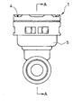
- FIG. 1 is a side view of a socket device according to an embodiment of the present invention.
- FIG. 2 is a side view showing the socket device as viewed from the right side in FIG.
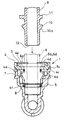
- FIG. 3 is a sectional view of the socket device and a connecting object connected to the socket device, taken along the line AA in FIG.
- FIG. 4 is a cross-sectional view of the socket device and a connecting object connected to the socket device, taken along the line BB in FIG.
- FIG. 5 is a cross-sectional view taken along the line CC in FIG.
- FIG. 6 is a side view showing a combined state of an inner cylinder body and a stopper which form the socket device, and an illustration of the outer cylinder body is omitted.
- FIG. 1 is a side view of a socket device according to an embodiment of the present invention.
- FIG. 2 is a side view showing the socket device as viewed from the right side in FIG.
- FIG. 3 is a sectional view of the socket device and a connecting object
- FIG. 7 is a cross-sectional view taken along the line DD in FIG.
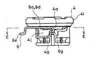
- FIG. 8 is a side view showing a combination state of the inner cylindrical body and the stopper which constitute the socket device, and shows a state where the stopper is moved to a position where the stopper retaining portion is caught by the convex portion of the inner cylindrical body.
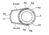
- FIG. 9 is a sectional view taken along the line EE in FIG.
- FIG. 10 is a plan view of the inner cylinder.
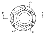
- 11 is a sectional view taken along the line FF in FIG.
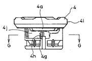
- FIG. 12 is a side view of the inner cylinder.
- FIG. 13 is a sectional view taken along the line GG in FIG.
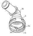
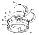
- FIG. 14 is a perspective view of the outer cylinder body.
- FIG. 15 is a perspective view of the outer cylinder body.
- FIG. 16 is a side view of the outer cylindrical body.
- FIG. 17 is a side view showing the outer cylindrical body as viewed from the left side in FIG. 16.
- the socket device 1 is a device having a structure in which, as the connecting object 9 is received, the socket object 1 is engaged with the connecting object 9 with one touch and connected to the connecting object 9.
- the socket device 1 has a tubular shape bent into an L shape.
- An inner cylinder body 4 and a stopper 6 described later are built in between the bent portion 2 of the socket device 1 and the one cylinder end 3.
- the stopper 6 contacts the orbiting collar 10 formed on the outside of the connecting object 9,
- the orbiting collar 10 is inserted into the stopper 6 from the built-in position, that is, the insertion of the connecting object 9 is allowed by the outward elastic deformation of the stopper 6, and the orbiting collar 10 is elastically returned to the stopper 6 at the insertion end position.
- the stopper 6 is engaged to maintain the connected state (see FIG. 4).
- the inside of the connecting object 9 and the inside of the socket device 1 communicate with each other to form a fluid flow path as a whole. That is, in the illustrated example, the socket device 1 functions as a pipe joint.
- the connecting object 9 has a cross section in a direction orthogonal to the cylinder axis direction that is substantially circular at any position, and at the insertion end position indicated by reference numeral 11 in FIG.
- the orbiting flange 10 is provided between the insertion restricting flange that abuts the inner step 4e of the body 4 and the pipe end indicated by reference numeral 12 in FIG.
- the distance between the pair of legs 6a of the stopper 6 in a state in which the stopper 6 is combined with the inner cylindrical body 4 to be described later is such that the outer diameter between the pipe end 12 of the connecting object 9 and the orbiting flange 10 and the orbiting flange 10 and the insertion restricting flange.
- the outer diameter is smaller than the outer diameter of the formation location of the circumferential collar 10.
- the side surface 10a of the orbiting collar 10 facing the tube end 12 side is provided with a slope that gradually increases the outer diameter of the connecting object 9 as it goes away from the tube end 12.
- the connected state can be released by moving a stopper 6 described later from this connected state in a direction orthogonal to a cylinder axis x of an inner cylindrical body 4 described later. ..
- the stopper 6 when the stopper 6 is moved from the state shown in FIG. 5 to the left side in FIG. 5 by utilizing the connecting portion of the stopper 6 described later, the cylinder axis x of the inner cylindrical body 4 indicated by the symbol y in FIG.
- a stopper portion 6g (see FIGS. 6 to 9) of a stopper 6 which will be described later and located on the right side of an imaginary center line that bisects the inner cylindrical body 4 is guided to the outer surface 4j of the inner cylindrical body 4 and is moved to the left side.
- the stopper 6 is moved and elastically deformed so that the distance between the pair of leg portions 6a is enlarged.
- the stopper portion 6g is caught by a convex portion 4g formed on the inner cylindrical body 4 and described later. 5 is prevented from moving to the left side, the distance between the pair of leg portions 6a is maximized, and the intermediate portion 6d of the pair of leg portions 6a is not positioned in the inner cylindrical body 4 (see FIG. 9). ).
- the connecting target 9 can be extracted from the socket device 1.
- the socket device 1 includes an inner cylinder body 4, an outer cylinder body 5, and a stopper 6 made of a metal wire.
- the inner cylindrical body 4 has split grooves 4a on both sides sandwiching the cylindrical axis x, which are continuous with each other in a direction intersecting with the cylindrical axis x. In the area where the split groove 4a is formed, the inner cylindrical body 4 communicates with the inside and outside of the split groove 4a.
- the inner cylinder 4 is substantially cylindrical and both ends of the cylinder are open.
- an inner step 4e facing the one cylinder end 4d side is formed on the one cylinder end 4d side of the introduction side of the connecting object 9 located on the upper side of the inner cylinder body 4 in FIG.
- the connecting object 9 can be inserted into the socket device 1 up to a position where the insertion restricting flange 11 abuts against the inner step 4e.
- the split groove 4a is formed between the other cylindrical end 4f of the inner cylindrical body 4 located on the lower side in FIG. 4 and the inner step 4e. Further, the split groove 4a is formed along an imaginary straight line orthogonal to the center line y. The split groove 4a communicates the inside and the outside of the inner cylindrical body 4 in the range where it is formed.
- One groove end 4b of the split groove 4a is located on one side across the center line y, and the other groove end 4c of the split groove 4a is located on the other side across the center line y (FIG. 4).
- a convex portion 4g for the retaining portion 6g of the stopper 6 is formed outside the inner cylindrical body 4 and at a position located on the center line y.
- the convex portion 4g is formed at a position between the other cylinder end 4f of the inner cylinder body 4 and the split groove 4a (see FIG. 6).
- the convex portions 4g are formed on both sides of the inner cylindrical body 4 with the cylinder axis x therebetween.
- the side surface 4h of the convex portion 4g facing the introduction hole 5a of the outer cylinder body 5 described later is inclined (see FIG.
- the outer cylindrical body 5 has an introduction hole 5a communicating with the split groove 4a.
- both ends of the outer cylinder 5 are open.
- the bent portion 2 of the socket device 1 is formed by the bent portion 5b of the outer cylindrical body 5.
- the inner tubular body 4 is built in between the bent portion 5b and the one tubular end 5c of the outer tubular body 5 which is located on the upper side in FIG.
- the inner cylindrical body 4 is moved to a position where the flange portion 4i formed on the outer side of the inner cylindrical body 4 on the one cylindrical end 4d side of the inner cylindrical body 4 abuts on the one cylindrical end 5c of the outer cylindrical body 5.
- the other cylinder end 4f is inserted into the outer cylinder body 5 first.
- the outer cylinder body 5 and the inner cylinder body 4 are integrated by welding the flange portion 4i of the inner cylinder body 4 and the one cylinder end 5c of the outer cylinder body 5 at the butting point.
- the socket device 1 is configured.
- Numeral 8 in FIG. 3 is a seal ring interposed between the other cylinder end 4f of the inner cylinder 4 and the intermediate step of the outer cylinder 5.
- a space 7 is formed between the inner tubular body 4 and the outer tubular body 5 between the flange portion 4i of the inner tubular body 4 and the other tubular end 4f (see FIG. 5).
- an introduction hole 5a communicating with one of the two division grooves 4a of the inner cylinder body 4 and an introduction hole communicating with the other of the two division grooves 4a of the inner cylinder body 4 are introduced.
- the hole 5a is formed. That is, the outer cylindrical body 5 is formed with two introduction holes 5a.
- One of the two introduction holes 5a (upper side in FIG. 5) communicates with the other groove end 4c on the left side in FIG. 7 of the two split grooves 4a, and the other of the two introduction holes 5a (lower side in FIG. 5).
- a regulation portion 5d which will be described later, is formed outside the outer cylindrical body 5 at a side portion of the outer cylindrical body 5 located between the two introduction holes 5a (FIG. 1). reference).
- the restricting portion 5d includes a first contact body 5e that contacts the connecting portion 6e of the stopper 6 from the one cylinder end 5c side of the outer cylinder body 5 and a second contact body that contacts the bending portion 5b side. And 5f.
- the first contact body 5e is formed by a step portion located between the two introduction holes 5a and directed toward the bent portion 5b.
- the second abutment body 5f has a rib shape formed directly below the edge of the two introduction holes 5a located on the bent portion 5b side.
- the second contact body 5f has a rib shape extending along the cylinder axis x direction of the inner cylinder body 4.
- An end portion of the second contact body 5f located on the introduction hole 5a side is located between the first contact body 5e and the first contact body 5e as it approaches the first contact body 5e. It is provided with an inclined portion 5g for gradually reducing the distance along the direction.
- the end portion of the second contact body 5f located on the introduction hole 5a side has an inner cylindrical body at the back of the inclined portion 5g (between the portion of the inclined portion 5g closest to the introduction hole 5a and the introduction hole 5a).
- a distance z between the holding portion 5h and the first contact body 5e in the direction along the cylinder axis x of the inner cylindrical body 4 is substantially equal to the thickness of the connecting portion 6e of the stopper 6 described later. (See Figure 3).
- the stopper 6 is one leg that positions the intermediate portion 6d, which is introduced into one of the split grooves 4a through the introduction hole 5a and is located between the distal end 6b and the proximal end 6c, inside the inner cylindrical body 4.
- the other leg portion that positions the portion 6a and the intermediate portion 6d, which is introduced into the other of the split grooves 4a through the introduction hole 5a and is located between the tip 6b and the base end 6c, inside the inner cylindrical body 4.
- 6 g see FIG. 5).
- the stopper 6 is formed by molding a metal wire rod.
- the stopper 6 has a U shape by the pair of legs 6a and the connecting portion 6e.
- the retaining portion 6g is configured by bending the tip end 6b of the leg portion 6a in a direction along the cylinder axis x of the inner cylinder body 4 (see FIG. 6).
- the connecting portion 6e is bent by a bending portion 6f formed by bending the retaining portion 6g in the same direction and in the same direction as that along the cylinder axis x of the inner cylindrical body 4. It is integrated with the leg portion 6a and is positioned below the leg portion 6a in FIG.
- the connection target 9 is connected. The engagement force of the stopper 6 can be increased.
- the leg portion 6a of the stopper 6 is introduced into the split groove 4a of the inner cylinder body 4 through the introduction hole 5a.
- the socket device 1 is configured.
- the leg portions 6a of the stopper 6 corresponding to the two introduction holes 5a are introduced, the retaining portions 6g are guided to the outer surface 4j of the inner cylindrical body 4 in the space 7 and the leg portions 6a are temporarily moved. Although it is bent outward, when the retaining portion 6g exceeds the center line y, the outer diameter of the inner cylindrical body 4 in the direction orthogonal to the introduction direction (of the inner cylindrical body 4 in contact with the pair of retaining portions 6g Since the distance between the outer surfaces 4j gradually becomes smaller, the leg portion 6a is bent back inward, and the intermediate portion 6d enters the inside of the inner cylindrical body 4 through the split groove 4a (FIGS. 5 and 6). reference).
- the introduction hole 5a has a long hole shape that is long in the cylinder axis x direction of the inner cylindrical body 4, and the retaining portion 6g can be introduced therein.
- the retaining portion 6g comes into contact with the outer surface 4j of the inner cylindrical body 4 immediately below the split groove 4a, and only the intermediate portion 6d enters the inside of the inner cylindrical body 4 through the split groove 4a.
- the distance between the pair of leg portions 6a in the stopper 6 is smaller than the outer diameter of the portion of the connecting target 9 where the orbiting collar 10 is formed.
- the stopper 6 is incorporated by inserting the intermediate portion 6d of the leg portion 6a into the split groove 4a of the inner cylindrical body 4 located in the outer cylindrical body 5, and the intermediate portion 6d engaged with the connecting object 9 is formed. Since it is located in the outer cylinder body 5, it is possible to prevent an unexpected external force from acting on the intermediate portion 6d, adhesion of foreign matter, and the like as much as possible, and the engagement state of the stopper 6 with respect to the connecting target 9 is stable. Maintained at.
- the retaining portion 6g is configured to overcome the convex portion 4g formed on the outer side of the inner cylindrical body 4 by the elastic deformation of the stopper 6. ..
- the connection state of the socket device 1 and the connecting object 9 can be released by moving the stopper 6 in a direction orthogonal to the cylinder axis x of the inner cylinder body 4 from this connection state.
- the operation of moving the stopper 6 beyond the position where the protrusion 4g is caught by the retaining portion 6g is blocked (see FIGS. 8 and 9).
- the stopper 6 will not fall out even if the releasing operation as described above is performed.
- the introduction hole 5a into which one of the pair of legs 6a of the stopper 6 in the outer cylinder 5 is introduced and the other of the legs 6a are introduced.
- the regulation section 5d is provided.
- the stopper 6 is guided in the connecting portion 6e by the inclined portion 5g of the second contact body 5f during the introduction process and gradually moved to the upper side in FIG. 1 to reach the holding portion 5h, At the end position of the introduction, it is sandwiched between the first contact body 5e and the sandwiching portion 5h of the second contact body 5f.
- the stopper 6 body can be held on the outer cylinder body 5 side without displacement, and the intermediate portion 6d of the leg portion 6a of the stopper 6 body can be held. It is possible to more stably secure the state in which is engaged with the connecting target 9.
- the present invention is not limited to the embodiments described above, but includes all embodiments that can achieve the object of the present invention.
Landscapes
- Engineering & Computer Science (AREA)
- General Engineering & Computer Science (AREA)
- Mechanical Engineering (AREA)
- Quick-Acting Or Multi-Walled Pipe Joints (AREA)
Abstract
内筒体は、その筒軸を挟んだ両側にそれぞれ、筒軸に交叉する向きに続く割溝を有している。外筒体は、割溝に連通する導入穴を有している。ストッパは、導入穴を通じて割溝の一方に導入されて先端と基端との間に位置される中間部を内筒体の内部に位置させる一対の脚部と、一対の脚部の基端間をつなぐ連接部と、導入後の割溝からの脚部の抜け出しを阻止する抜け止め部とを備えている。受け入れられるコネクティング対象に対し、ストッパの中間部において係合するようになっている。
Description
この発明は、ソケット装置の改良に関する。
クイックコネクタアセンブリに関し、特許文献1に示されるものがある。この特許文献1のものは、雄型連結部材の収容部を持った雌型連結部材を有する。雌型連結部材には、貫通スロットを通じて雌型連結部材内に一部を入り込ませたワイヤよりなる保持装置が組み合わされている。この特許文献1のものにあっては、前記収容部に雄型連結部材を差し込むと、雄型連結部材に前記保持装置の一部が係合され、これにより両部材が接続されるようになっている。
しかるに、前記特許文献1のものにあっては、ワイヤよりなる保持装置は、雌型連結部材の外側に露出しており、したがって、この保持装置に予期しない外力の作用や異物の付着などが生じる可能性が否定できないところであり、このような事態が生じた場合、雄型連結部材象に対する保持装置の係合状態が損なわれるおそれがある。
この発明が解決しようとする主たる問題点は、この種のソケット装置ないしコネクタアセンブリにおいて、コネクティング対象に対するストッパの係合状態をできるだけ安定的に維持できるようにする点にある。
前記課題を達成するために、この発明にあっては、ソケット装置を、
内筒体と、
外筒体と、
金属線材からなるストッパとを備え、
前記内筒体は、その筒軸を挟んだ両側にそれぞれ、前記筒軸に交叉する向きに続く割溝を有しており、
前記外筒体は、前記割溝に連通する導入穴を有しており、
前記ストッパは、前記導入穴を通じて前記割溝の一方に導入されて先端と基端との間に位置される中間部を前記内筒体の内部に位置させる一方の脚部と、前記導入穴を通じて前記割溝の他方に導入されて先端と基端との間に位置される中間部を前記内筒体の内部に位置させる他方の脚部と、前記一方の脚部及び前記他方の脚部の基端間をつなぐ連接部と、前記導入後の前記割溝からの前記脚部の抜け出しを阻止する抜け止め部とを備えており、
受け入れられるコネクティング対象に対し、前記ストッパの中間部において係合するようにしてなる、ものとした。
内筒体と、
外筒体と、
金属線材からなるストッパとを備え、
前記内筒体は、その筒軸を挟んだ両側にそれぞれ、前記筒軸に交叉する向きに続く割溝を有しており、
前記外筒体は、前記割溝に連通する導入穴を有しており、
前記ストッパは、前記導入穴を通じて前記割溝の一方に導入されて先端と基端との間に位置される中間部を前記内筒体の内部に位置させる一方の脚部と、前記導入穴を通じて前記割溝の他方に導入されて先端と基端との間に位置される中間部を前記内筒体の内部に位置させる他方の脚部と、前記一方の脚部及び前記他方の脚部の基端間をつなぐ連接部と、前記導入後の前記割溝からの前記脚部の抜け出しを阻止する抜け止め部とを備えており、
受け入れられるコネクティング対象に対し、前記ストッパの中間部において係合するようにしてなる、ものとした。
前記抜け止め部は、前記ストッパの前記脚部の前記先端を、前記内筒体の筒軸に沿う向きに折り曲げさせてなり、
前記導入の過程で、前記内筒体の外側に形成された凸部を前記ストッパの弾性変形により前記抜け止め部が乗り越えるようにしておくことが、この発明の態様の一つとされる。
前記導入の過程で、前記内筒体の外側に形成された凸部を前記ストッパの弾性変形により前記抜け止め部が乗り越えるようにしておくことが、この発明の態様の一つとされる。
また、前記外筒体における前記ストッパの一対の前記脚部の一方が導入される前記導入穴と、前記脚部の他方が導入される前記導入穴との間に、前記ストッパの前記脚部の前記導入の終了位置において前記連接部に当たって前記連接部の前記内筒体の筒軸に沿う向きの移動を規制する規制部を備えさせておくことが、この発明の態様の一つとされる。
また、前記内筒体と前記外筒体とを溶着させておくことが、この発明の態様の一つとされる。
この発明によれば、外筒体の導入穴を通じて内筒体の割溝にストッパの脚部を導入させてソケット装置を構成することから、コネクティング対象に対し係合される中間部を外筒体内に位置させて、かかる中間部に対する予期しない外力の作用や異物の付着などを可及的に防止することができ、コネクティング対象に対するストッパの係合状態をできるだけ安定的に維持することができる。
以下、図1~図17に基づいて、この発明の典型的な実施の形態について、説明する。この実施の形態にかかるソケット装置1は、コネクティング対象9を受け入れることに伴い、このコネクティング対象9にワンタッチで係合してこのコネクティング対象9と連結される構造を備えた装置である。
図示の例では、ソケット装置1は、L字状に屈曲した管状を呈している。ソケット装置1の屈曲部2と一方の筒端3との間に後述の内筒体4とストッパ6が内蔵されている。図示の例では、管状をなすコネクティング対象9をソケット装置1の一方の筒端3からソケット装置1内に差し込むと、コネクティング対象9の外側に形成された周回鍔10にストッパ6が当接してこのストッパ6の内蔵位置より奥への周回鍔10の入り込み、つまり、コネクティング対象9の差し込みをストッパ6の外向きの弾性変形により許容させると共に、差し込み終了位置におけるストッパ6の弾性復帰により前記周回鍔10にストッパ6を係合させて前記連結状態を維持するようにしている(図4参照)。
図示の例では、かかる連結によって、コネクティング対象9の内部とソケット装置1の内部とが連通して、全体として流体の流路を形成するようになっている。すなわち、図示の例では、ソケット装置1は、管継ぎ手として機能するようになっている。
図示の例では、コネクティング対象9は、その筒軸方向に直交する向きの断面をいずれの位置においても実質的に円形状とすると共に、図4において符号11で示す差し込み終了位置において後述の内筒体4の内側段差4eに突き当たる差し込み規制鍔と、図4において符号12で示す管端との間に、前記周回鍔10を備えている。後述する内筒体4に組み合わされた状態におけるストッパ6の一対の脚部6a間の距離は、コネクティング対象9の管端12と周回鍔10との間の外径及び周回鍔10と差し込み規制鍔11との間の外径と実質的に等しいか、やや小さいが、周回鍔10の形成箇所の外径よりも小さくなっている。周回鍔10における管端12側に向けられた側面10aは、前記管端12から離れるに従ってコネクティング対象9の外径を漸増させる傾斜を備えている。ソケット装置1にコネクティング対象9を差し込むと、前記周回鍔10の側面10aにストッパ6の脚部6aが当たり、ストッパ6は一対の脚部6a間の距離を拡大する向きに弾性変形され、コネクティング対象9の差し込みが許容される。ストッパ6の脚部6aが周回鍔10と差し込み規制鍔11の間に入り込む位置までコネクティング対象9が差し込まれると、ストッパ6が弾性復帰して図4における上方から周回鍔10に引っかかる。これにより前記連結状態が維持される。
この実施の形態にあっては、前記連結状態は、この連結状態から後述のストッパ6を後述の内筒体4の筒軸xに直交する向きに移動操作することで解除できるようになっている。図示の例では、図5の状態から、後述のストッパ6の連接部を利用して図5における左側にストッパ6を移動させると、図5において符号yで示す内筒体4の筒軸xを通って内筒体4を二分する仮想の中心線よりも右側に位置される後述するストッパ6の抜け止め部6g(図6乃至9参照)が内筒体4の外面4jに案内されながら左側に移動され、ストッパ6が弾性変形されて一対の脚部6a間の距離が拡大されるようになっている。ストッパ6がその抜け止め部6gを前記中心線y上に位置される位置まで移動されると、抜け止め部6gは内筒体4に形成された後述の凸部4gに引っかかってそれ以上の図5における左側への移動が阻止されると共に、一対の脚部6a間の距離は最大化され、内筒体4内に一対の脚部6aの中間部6dは位置されないようになる(図9参照)。これにより、ソケット装置1内からコネクティング対象9を抜き出すことが可能となる。
かかるソケット装置1は、内筒体4と、外筒体5と、金属線材からなるストッパ6とを備えている。
前記内筒体4は、その筒軸xを挟んだ両側にそれぞれ、前記筒軸xに交叉する向きに続く割溝4aを有している。この割溝4aの形成範囲において、前記内筒体4は割溝4aにおいて内外に連通している。
前記内筒体4は、実質的に円筒状をなすと共に筒両端を共に開放している。図示の例では、内筒体4の図4において上側に位置されるコネクティング対象9の導入側の一方筒端4d側には、この一方筒端4d側に向いた内側段差4eが形成されており、前記コネクティング対象9は、この内側段差4eに前記差し込み規制鍔11を突き当てる位置までソケット装置1内に差し込めるようになっている。
図示の例では、前記割溝4aは、内筒体4における図4において下側に位置される他方筒端4fと前記内側段差4eとの間に形成されている。また、前記割溝4aは、前記中心線yに直交する仮想の直線に沿うように形成されている。前記割溝4aは、その形成範囲において、内筒体4の内外を連通させている。割溝4aの一方の溝端4bは前記中心線yを挟んだ一方側に位置し、割溝4aの他方の溝端4cは前記中心線yを挟んだ他方側に位置している(図4)。
また、図示の例では、内筒体4の外側であって、前記中心線y上に位置される箇所に、前記ストッパ6の抜け止め部6gに対する凸部4gが形成されている。図示の例では、前記凸部4gは内筒体4の他方筒端4fと割溝4aとの間となる箇所に形成されている(図6参照)。また、図示の例では、凸部4gは、前記内筒体4の筒軸xを挟んだ両側にそれぞれ形成されている。図示の例では、凸部4gにおける後述の外筒体5の導入穴5aに向けられた側面4hは傾斜しており(図5参照)、導入穴5aを通じて外筒体5と内筒体4との間に形成された空間7内に導入されたストッパ6の脚部6aは抜け止め部6gをこの凸部4gの側面4hに突き当てて外向き(前記筒軸xから離れる向き)に撓まされてこの凸部4gを乗り越えるようになっている。
前記外筒体5は、前記割溝4aに連通する導入穴5aを有している。
図示の例では、外筒体5は筒両端を共に開放させている。また、外筒体5の屈曲部5bによってソケット装置1の前記屈曲部2が形成されている。この屈曲部5bと外筒体5における図3において上側に位置される一方筒端5cとの間に、内筒体4が内蔵されるようになっている。
図示の例では、内筒体4の前記一方筒端4d側において内筒体4の外側に形成されたフランジ部4iが外筒体5の一方筒端5cに突き当たる位置まで、内筒体4はその他方筒端4fを先にして外筒体5内に差し込まれている。図示の例では、この内筒体4のフランジ部4iと外筒体5の一方筒端5cとをその突き当たり箇所で溶着させることで、外筒体5と内筒体4とを一体化させてソケット装置1を構成させている。
図3中、符号8で示すのは、内筒体4の他方筒端4fと外筒体5の中間段差との間に介在されたシールリングである。
内筒体4のフランジ部4iと他方筒端4fとの間においては、内筒体4と外筒体5との間に空間7が形成されている(図5参照)。
また、外筒体5の側部には、内筒体4の二カ所の割溝4aの一方に連通する導入穴5aと、内筒体4の二カ所の割溝4aの他方に連通する導入穴5aとが形成されている。すなわち、外筒体5には二カ所の導入穴5aが形成されている。二カ所の導入穴5aの一方(図5における上側)は二カ所の割溝4aの一方の図7における左側の他方溝端4cに連通し、二カ所の導入穴5aの他方(図5における下側)は二カ所の割溝4aの他方の図7における左側の他方溝端4cに連通するようになっている。
また、外筒体5の側部であって、二カ所の導入穴5aの間に位置される箇所には、外筒体5の外側において、後述の規制部5dが形成されている(図1参照)。図示の例では、この規制部5dは、ストッパ6の連接部6eに外筒体5の一方筒端5c側から接する第一当接体5eと、前記屈曲部5b側から接する第二当接体5fとから構成されている。
図示の例では、第一当接体5eは、二カ所の導入穴5a間にあって、前記屈曲部5b側に向けられた段部によって構成されている。
また、第二当接体5fは、二カ所の導入穴5aにおける前記屈曲部5b側に位置される穴縁の直下となる位置にそれぞれ形成されたリブ状を呈している。第二当接体5fは、内筒体4の筒軸x方向に沿って延びるリブ状を呈している。第二当接体5fの導入穴5a側に位置される端部は、第一当接体5eに近づくに連れて第一当接体5eとの間の前記内筒体4の筒軸x方向に沿う向きの距離を漸減させる傾斜部5gを備えている。第二当接体5fの導入穴5a側に位置される端部は、傾斜部5gの奥(傾斜部5gにおける導入穴5aに最も近づいた箇所と導入穴5aとの間)においては内筒体4の筒軸xに直交する向きの挟持部5hを備えている。この挟持部5hと第一当接体5eとの間の前記内筒体4の筒軸x方向に沿う向きの距離zは、後述のストッパ6の連接部6eの太さと実質的に等しくなっている(図3参照)。
前記ストッパ6は、前記導入穴5aを通じて前記割溝4aの一方に導入されて先端6bと基端6cとの間に位置される中間部6dを前記内筒体4の内部に位置させる一方の脚部6aと、前記導入穴5aを通じて前記割溝4aの他方に導入されて先端6bと基端6cとの間に位置される中間部6dを前記内筒体4の内部に位置させる他方の脚部6aと、前記一方の脚部6a及び前記他方の脚部6aの基端6c間をつなぐ連接部6eと、前記導入後の前記割溝4aからの前記脚部6aの抜け出しを阻止する抜け止め部6gとを備えている(図5参照)。
図示の例では、ストッパ6は、金属の線材を成形することで構成されている。一対の脚部6aと連接部6eとによって、ストッパ6はコ字状を呈している。抜け止め部6gは、脚部6aの先端6bを前記内筒体4の筒軸xに沿う向きに折り曲げさせて構成されている(図6参照)。図示の例では、連接部6eは、抜け止め部6gと実質的に同じ寸法分、同じ向きに、前記内筒体4の筒軸xに沿う向きに折り曲げて形成された折り曲げ部6fを介して脚部6aと一体化されており、脚部6aよりも図3における下側に位置されるようになっている。ストッパ6の一対の脚部6aの抜け止め部6g間の距離を、連接部6e側での一対の脚部6a間の距離よりも狭めるようにストッパ6を形成しておけば、コネクティング対象9に対するストッパ6の係合力を高めることができる。
この実施の形態にあっては、前記のように組み合わされた外筒体5と内筒体4に対し、前記導入穴5aを通じてストッパ6の脚部6aを内筒体4の割溝4aに導入させることで、ソケット装置1を構成させている。
具体的には、二カ所の導入穴5aに対応するストッパ6の脚部6aを導入すると、前記空間7内において内筒体4の外面4jに抜け止め部6gが案内されて脚部6aは一旦外側に撓み出されるが、この抜け止め部6gが前記中心線yを超えるとこの導入方向に直交する向きでの内筒体4の外径(一対の抜け止め部6gが接する内筒体4の外面4j間の距離)は次第に小さくなることから、脚部6aは内側に撓み戻し、前記中間部6dは割溝4aを通じて内筒体4の内部に入り込むようになっている(図5及び図6参照)。
すなわち、導入穴5aは、前記内筒体4の筒軸x方向に長い長穴状をなし、抜け止め部6gを導入可能となっている。抜け止め部6gは、割溝4a直下の内筒体4の外面4jに当接し、中間部6dのみが割溝4aを介して内筒体4の内部に入り込むようになっている。
かかるストッパ6における一対の脚部6a間の距離は、前述のように、コネクティング対象9の周回鍔10の形成箇所の外径よりも小さくなっていることから、このように内筒体4の割溝4aにストッパ6の脚部6aを導入させた状態からソケット装置1にコネクティング対象9を差し込むと、前記のようにコネクティング対象9に対し、前記ストッパ6の中間部6dを係合させることができる。
ストッパ6は外筒体5内に位置される内筒体4の割溝4aに脚部6aの中間部6dを入り込ませて組み込まれており、コネクティング対象9に対し係合される中間部6dを外筒体5内に位置させることから、かかる中間部6dに対する予期しない外力の作用や異物の付着などを可及的に防止することができ、コネクティング対象9に対するストッパ6の係合状態は安定的に維持される。
また、この実施の形態にあっては、前記導入の過程で、前記内筒体4の外側に形成された凸部4gを前記ストッパ6の弾性変形により前記抜け止め部6gが乗り越えるようにしている。前記のように、ソケット装置1とコネクティング対象9との連結状態は、この連結状態からストッパ6を内筒体4の筒軸xに直交する向きに移動操作することで解除できるようになっているが、前記凸部4gが前記抜け止め部6gが引っかかる位置から先のストッパ6の移動操作は阻止される(図8、図9参照)。これにより、ストッパ6を一旦前記のように組み込んだ後は、前記のような解除操作をしてもストッパ6を脱落させてしまうことはない。
また、この実施の形態にあっては、前記外筒体5における前記ストッパ6の一対の前記脚部6aの一方が導入される前記導入穴5aと、前記脚部6aの他方が導入される前記導入穴5aとの間に、前記ストッパ6の前記脚部6aの前記導入の終了位置において前記連接部6eに当たって前記連接部6eの前記内筒体4の筒軸xに沿う向きの移動を規制する規制部5dを備えさせている。
具体的には、前記ストッパ6は前記導入の過程で前記第二当接体5fの傾斜部5gに連接部6eを案内されて、図1における上側に徐々に移動され、挟持部5hに至り、前記導入の終了位置において、前記第一当接体5eと前記第二当接体5fの挟持部5hとの間で挟み込まれるようになっている。これにより、前記ストッパ6の前記脚部6aの前記導入の終了位置において、ストッパ6体を位置ズレなく外筒体5側に保持させることができ、ストッパ6体の前記脚部6aの中間部6dをコネクティング対象9に係合させた状態を一層安定的に確保させることができる。
なお、当然のことながら、本発明は以上に説明した実施態様に限定されるものではなく、本発明の目的を達成し得るすべての実施態様を含むものである。
x 筒軸
4 内筒体
4a 割溝
5 外筒体
5a 導入穴
6 ストッパ
6a 脚部
6b 先端
6c 基端
6d 中間部
6e 連接部
6g 抜け止め部
9 コネクティング対象
なお、2019年1月11日に出願された日本国特願2019-003714号の明細書、特許請求の範囲、図面及び要約書の全内容をここに引用し、本発明の明細書の開示として、取り入れるものである。
4 内筒体
4a 割溝
5 外筒体
5a 導入穴
6 ストッパ
6a 脚部
6b 先端
6c 基端
6d 中間部
6e 連接部
6g 抜け止め部
9 コネクティング対象
なお、2019年1月11日に出願された日本国特願2019-003714号の明細書、特許請求の範囲、図面及び要約書の全内容をここに引用し、本発明の明細書の開示として、取り入れるものである。
Claims (4)
- 内筒体と、
外筒体と、
金属線材からなるストッパとを備え、
前記内筒体は、その筒軸を挟んだ両側にそれぞれ、前記筒軸に交叉する向きに続く割溝を有しており、
前記外筒体は、前記割溝に連通する導入穴を有しており、
前記ストッパは、前記導入穴を通じて前記割溝の一方に導入されて先端と基端との間に位置される中間部を前記内筒体の内部に位置させる一方の脚部と、前記導入穴を通じて前記割溝の他方に導入されて先端と基端との間に位置される中間部を前記内筒体の内部に位置させる他方の脚部と、前記一方の脚部及び前記他方の脚部の基端間をつなぐ連接部と、前記導入後の前記割溝からの前記脚部の抜け出しを阻止する抜け止め部とを備えており、
受け入れられるコネクティング対象に対し、前記ストッパの中間部において係合するようにしてなる、ソケット装置。 - 前記抜け止め部は、前記ストッパの前記脚部の前記先端を、前記内筒体の筒軸に沿う向きに折り曲げさせてなり、
前記導入の過程で、前記内筒体の外側に形成された凸部を前記ストッパの弾性変形により前記抜け止め部が乗り越えるようにしてなる、請求項1に記載のソケット装置。 - 前記外筒体における前記ストッパの一対の前記脚部の一方が導入される前記導入穴と、前記脚部の他方が導入される前記導入穴との間に、前記ストッパの前記脚部の前記導入の終了位置において前記連接部に当たって前記連接部の前記内筒体の筒軸に沿う向きの移動を規制する規制部を備えさせてなる、請求項1又は請求項2に記載のソケット装置。
- 前記内筒体と前記外筒体とを溶着させてなる、請求項1~請求項3のいずれか1項に記載のソケット装置。
Applications Claiming Priority (2)
| Application Number | Priority Date | Filing Date | Title |
|---|---|---|---|
| JP2019-003714 | 2019-01-11 | ||
| JP2019003714A JP6975186B2 (ja) | 2019-01-11 | 2019-01-11 | ソケット装置 |
Publications (1)
| Publication Number | Publication Date |
|---|---|
| WO2020145264A1 true WO2020145264A1 (ja) | 2020-07-16 |
Family
ID=71520504
Family Applications (1)
| Application Number | Title | Priority Date | Filing Date |
|---|---|---|---|
| PCT/JP2020/000155 Ceased WO2020145264A1 (ja) | 2019-01-11 | 2020-01-07 | ソケット装置 |
Country Status (2)
| Country | Link |
|---|---|
| JP (1) | JP6975186B2 (ja) |
| WO (1) | WO2020145264A1 (ja) |
Citations (7)
| Publication number | Priority date | Publication date | Assignee | Title |
|---|---|---|---|---|
| JPH0533891A (ja) * | 1990-11-26 | 1993-02-09 | Nitta Moore Co Ltd | 管継手 |
| JPH08219352A (ja) * | 1995-02-09 | 1996-08-30 | Toto Ltd | 管継手 |
| JP2002267071A (ja) * | 2001-03-09 | 2002-09-18 | Inax Corp | ワンタッチジョイント |
| JP2003021287A (ja) * | 2001-07-05 | 2003-01-24 | Piolax Inc | スピゴット継手 |
| JP2004211891A (ja) * | 2002-12-18 | 2004-07-29 | Piolax Inc | チェッカー付きコネクタ |
| JP2005042794A (ja) * | 2003-07-28 | 2005-02-17 | Togo Seisakusho Corp | コネクタとそのコネクタに用いるクランプガイド及びクランプ |
| US20170363237A1 (en) * | 2016-06-17 | 2017-12-21 | Ti Group Automotive Systems, Llc | Quick connector |
-
2019
- 2019-01-11 JP JP2019003714A patent/JP6975186B2/ja active Active
-
2020
- 2020-01-07 WO PCT/JP2020/000155 patent/WO2020145264A1/ja not_active Ceased
Patent Citations (7)
| Publication number | Priority date | Publication date | Assignee | Title |
|---|---|---|---|---|
| JPH0533891A (ja) * | 1990-11-26 | 1993-02-09 | Nitta Moore Co Ltd | 管継手 |
| JPH08219352A (ja) * | 1995-02-09 | 1996-08-30 | Toto Ltd | 管継手 |
| JP2002267071A (ja) * | 2001-03-09 | 2002-09-18 | Inax Corp | ワンタッチジョイント |
| JP2003021287A (ja) * | 2001-07-05 | 2003-01-24 | Piolax Inc | スピゴット継手 |
| JP2004211891A (ja) * | 2002-12-18 | 2004-07-29 | Piolax Inc | チェッカー付きコネクタ |
| JP2005042794A (ja) * | 2003-07-28 | 2005-02-17 | Togo Seisakusho Corp | コネクタとそのコネクタに用いるクランプガイド及びクランプ |
| US20170363237A1 (en) * | 2016-06-17 | 2017-12-21 | Ti Group Automotive Systems, Llc | Quick connector |
Also Published As
| Publication number | Publication date |
|---|---|
| JP2020112218A (ja) | 2020-07-27 |
| JP6975186B2 (ja) | 2021-12-01 |
Similar Documents
| Publication | Publication Date | Title |
|---|---|---|
| JP5420991B2 (ja) | コネクタ | |
| CN104136068B (zh) | 无针连接器 | |
| KR200498486Y1 (ko) | 감소된 힘으로 수형 노즐의 삽입을 가능하게 하는 연결부의 암형 노즐 | |
| CN109661532B (zh) | 管接头及卡定构件 | |
| EP1681477A1 (en) | Snap ring | |
| JP4703044B2 (ja) | スピゴット継手 | |
| JP2018201600A (ja) | メスコネクタ | |
| JP2026063390A (ja) | チューブ管用継手 | |
| JP2009236206A (ja) | コネクタ | |
| JP6975186B2 (ja) | ソケット装置 | |
| JP7800299B2 (ja) | ナット及びボールねじ装置 | |
| KR102712264B1 (ko) | 관 조인트 부재 | |
| JP6188472B2 (ja) | スイッチ | |
| JP5868207B2 (ja) | コネクタ | |
| KR101954308B1 (ko) | 파이프 연결용 실링부재 | |
| JP5725564B2 (ja) | 連結継手及びセグメント | |
| WO2024117189A1 (ja) | 第一継手及び管継手 | |
| JP7424722B2 (ja) | 配管の分岐構造 | |
| JP7773017B2 (ja) | チューブ管用継手 | |
| JP2013164948A (ja) | 端子金具,バルブソケット | |
| JP4242811B2 (ja) | 管継手及びストッパ | |
| CN116745551B (zh) | 连接器 | |
| JP2025086850A (ja) | コネクタ | |
| JP2022098119A (ja) | 管継手 | |
| JP7286495B2 (ja) | 医療用コネクタ |
Legal Events
| Date | Code | Title | Description |
|---|---|---|---|
| 121 | Ep: the epo has been informed by wipo that ep was designated in this application |
Ref document number: 20738717 Country of ref document: EP Kind code of ref document: A1 |
|
| NENP | Non-entry into the national phase |
Ref country code: DE |
|
| 122 | Ep: pct application non-entry in european phase |
Ref document number: 20738717 Country of ref document: EP Kind code of ref document: A1 |