WO2020138167A1 - 車両の制動システム - Google Patents
車両の制動システム Download PDFInfo
- Publication number
- WO2020138167A1 WO2020138167A1 PCT/JP2019/050822 JP2019050822W WO2020138167A1 WO 2020138167 A1 WO2020138167 A1 WO 2020138167A1 JP 2019050822 W JP2019050822 W JP 2019050822W WO 2020138167 A1 WO2020138167 A1 WO 2020138167A1
- Authority
- WO
- WIPO (PCT)
- Prior art keywords
- braking force
- switching control
- regenerative braking
- vehicle
- friction
- Prior art date
- Legal status (The legal status is an assumption and is not a legal conclusion. Google has not performed a legal analysis and makes no representation as to the accuracy of the status listed.)
- Ceased
Links
Images


Classifications
-
- B—PERFORMING OPERATIONS; TRANSPORTING
- B60—VEHICLES IN GENERAL
- B60L—PROPULSION OF ELECTRICALLY-PROPELLED VEHICLES; SUPPLYING ELECTRIC POWER FOR AUXILIARY EQUIPMENT OF ELECTRICALLY-PROPELLED VEHICLES; ELECTRODYNAMIC BRAKE SYSTEMS FOR VEHICLES IN GENERAL; MAGNETIC SUSPENSION OR LEVITATION FOR VEHICLES; MONITORING OPERATING VARIABLES OF ELECTRICALLY-PROPELLED VEHICLES; ELECTRIC SAFETY DEVICES FOR ELECTRICALLY-PROPELLED VEHICLES
- B60L7/00—Electrodynamic brake systems for vehicles in general
- B60L7/24—Electrodynamic brake systems for vehicles in general with additional mechanical or electromagnetic braking
-
- B—PERFORMING OPERATIONS; TRANSPORTING
- B60—VEHICLES IN GENERAL
- B60T—VEHICLE BRAKE CONTROL SYSTEMS OR PARTS THEREOF; BRAKE CONTROL SYSTEMS OR PARTS THEREOF, IN GENERAL; ARRANGEMENT OF BRAKING ELEMENTS ON VEHICLES IN GENERAL; PORTABLE DEVICES FOR PREVENTING UNWANTED MOVEMENT OF VEHICLES; VEHICLE MODIFICATIONS TO FACILITATE COOLING OF BRAKES
- B60T8/00—Arrangements for adjusting wheel-braking force to meet varying vehicular or ground-surface conditions, e.g. limiting or varying distribution of braking force
- B60T8/17—Using electrical or electronic regulation means to control braking
Definitions
- the present invention relates to a vehicle braking system that generates a regenerative braking force and a friction braking force on a vehicle.
- Patent Document 1 describes an example of a vehicle braking system including a regenerative braking device that generates a regenerative braking force on the vehicle and a friction braking device that generates a friction braking force on the vehicle.
- the switching control that reduces the regenerative braking force and increases the friction braking force is performed.
- the target value of the regenerative braking force is decreased at a constant speed, while the target value of the friction braking force is increased at a constant speed.
- a braking system for a vehicle for solving the above-mentioned problems is a regenerative braking device for generating a regenerative braking force in a vehicle, a friction braking device for generating a friction braking force in a vehicle, and a total of the regenerative braking force and the friction braking force
- the control device increases the reduction rate of the regenerative braking force as time elapses from the start of the reduction of the regenerative braking force due to the start of the switching control.
- the rate of decrease of the regenerative braking force is small, so the rate of increase of the friction braking force is unlikely to increase.
- a difference between the target value of the friction braking force and the actual friction braking force is unlikely to occur. That is, it is possible to suppress a decrease in the controllability of the braking force of the vehicle during the switching control.
- the replacement control execution period is the same, it is possible to increase the integrated value of the regenerative braking force during the replacement control, as compared with the case where the reduction speed of the regenerative braking force is constant.
- the larger the integrated value the larger the amount of charge of the on-vehicle battery during the switching control. Therefore, the energy efficiency of the vehicle can be improved without delaying the start of the switching control.
- the block diagram which shows typically the braking system of the vehicle of an embodiment.
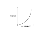
- the graph which shows the relationship between the brake supply amount which is the amount of the brake fluid supplied to a wheel cylinder, and the WC pressure which is the hydraulic pressure in a wheel cylinder.
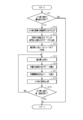
- the flowchart which shows the process routine which the control apparatus of the same braking system performs.
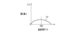
- the figure which shows the change profile showing the relationship between the elapsed time from the start time of the switching control and the correction amount.
- (A)-(e) is a timing chart when switching control is implemented.
- FIG. 1 shows a vehicle including a braking system 10 of this embodiment.
- Braking force is applied to the front wheels 11 and the rear wheels 12 of the vehicle by the operation of the braking mechanism 13.
- Each braking mechanism 13 is configured such that the higher the WC pressure PWC that is the hydraulic pressure in the wheel cylinder 131, the greater the force that presses the friction material 133 against the rotating body 132 that rotates integrally with the wheels 11 and 12. That is, each braking mechanism 13 can apply greater braking force to the wheels 11 and 12 as the WC pressure PWC is higher.
- the vehicle includes a drive device 20, a friction braking device 30 that generates a friction braking force BFF on the vehicle, and a control device 40 that controls the drive device 20 and the friction braking device 30.
- the “friction braking force BFF” mentioned here is the sum of the braking forces applied to the wheels 11 and 12 by the operation of the braking mechanism 13.
- the drive device 20 includes a motor generator 21.
- the motor generator 21 functions as an electric motor, the driving force output from the motor generator 21 is input to the front wheels 11.
- the motor generator 21 is made to function as a generator, the motor generator 21 generates power according to the rotation speed of the front wheels 11.
- the regenerative braking force BFR can be generated in the vehicle.
- the regenerative braking force BFR increases as the amount of power generated by the motor generator 21 increases. That is, in the present embodiment, the motor generator 21 corresponds to the “regenerative braking device” that generates the regenerative braking force BFR in the vehicle.
- the friction braking device 30 is configured to be able to supply brake fluid to each wheel cylinder 131.
- the friction braking device 30 includes an electric motor 31 and a pump 32 that uses the electric motor 31 as a power source. That is, the pump 32 is an electric pump. The brake fluid discharged from the pump 32 is supplied into each wheel cylinder 131. At this time, the larger the driving amount of the electric motor 31, the higher the WC pressure PWC can be made. That is, the pump 32 is a pressurizing source that increases the WC pressure PWC.
- Examples of such a friction braking device 30 include a device disclosed in "Japanese Patent Application Laid-Open No. 2008-184057" and a device disclosed in "Japanese Patent Application Laid-Open No. 2017-154563". According to such a friction braking device 30, the electric motor 31 is driven when increasing the WC pressure PWC, and the driving of the electric motor 31 is stopped when maintaining the WC pressure PWC.
- FIG. 2 shows the WC pressure PWC in the wheel cylinder 131 to which the brake fluid is supplied from the friction braking device 30 and the brake supply amount VBP which is the amount of the brake fluid supplied from the friction braking device 30 to the wheel cylinder 131.
- the WC pressure PWC increases as the brake supply amount VBP increases.
- the pressure increase gradient of the WC pressure PWC which is the pressure increase amount of the WC pressure PWC with respect to the increase of the brake supply amount VBP, increases as the brake supply amount VBP increases. That is, when supplying a prescribed amount of brake fluid to the wheel cylinder 131, the lower the WC pressure PWC, the smaller the amount of increase in the WC pressure PWC.
- the WC pressure PWC has a correlation with the friction braking force BFF. Therefore, when supplying a prescribed amount of brake fluid to the wheel cylinder 131, it is difficult to increase the friction braking force BFF as the WC pressure PWC is lower.
- the control device 40 performs cooperative control of the motor generator 21 and the friction braking device 30 during vehicle braking. That is, the control device 40 controls the motor generator 21 and the friction braking device 30 so that the sum of the regenerative braking force BFR and the friction braking force BFF becomes the same as the required braking force BFRQ during vehicle braking.
- the required braking force BFRQ is a required value of the braking force for the vehicle. Therefore, in the present embodiment, the braking system 10 is configured by the motor generator 21, the friction braking device 30, and the control device 40.
- the control device 40 has an overall control unit 41, a regeneration control unit 42, and a friction control unit 43 as functional units for performing cooperative control.
- the integrated control unit 41 determines the required braking force BFRQ. For example, when the braking operation member 14 such as the brake pedal is operated by the driver of the vehicle, the overall control unit 41 requests that the value increase as the braking operation amount INP detected by the operation amount sensor 101 increases. The braking force BFRQ is derived. When the vehicle travels by automatic driving, the overall control unit 41 derives the required braking force BFRQ based on the deceleration of the vehicle requested by the automatic driving control device 50.
- the overall control unit 41 determines the target regenerative braking force BFRTr that is the target value of the regenerative braking force BFR and the target friction braking force BFFTr that is the target value of the friction braking force BFF based on the derived required braking force BFRQ. Derive.
- the regenerative control unit 42 controls the motor generator 21 based on the target regenerative braking force BFRTr derived by the overall control unit 41. That is, the regenerative control unit 42 causes the motor generator 21 to generate electric power based on the target regenerative braking force BFRTr to bring the regenerative braking force BFR generated in the vehicle close to the target regenerative braking force BFRTr.
- the friction control unit 43 controls driving of the electric motor 31 of the friction braking device 30 based on the target friction braking force BFFTr derived by the overall control unit 41. That is, the friction control unit 43 causes the brake fluid to be discharged from the pump 32 based on the target friction braking force BFFTr to bring the friction braking force BFF generated in the vehicle close to the target friction braking force BFFTr.
- This processing routine is repeatedly executed when the regenerative braking force BFR is applied to the vehicle.
- the replacement control is control for replacing the regenerative braking force BFR with the friction braking force BFF, and is control for decreasing the regenerative braking force BFR and increasing the friction braking force BFF.
- the switching control is performed when the vehicle is stopped by applying a braking force. Then, when the vehicle body speed VS of the vehicle that is decelerated by applying the braking force decreases to the start determination speed VSTh1, the switching control start condition is satisfied. That is, the start determination speed VSTh1 corresponds to the vehicle body speed VS at the start of the switching control.
- the start determination speed VSTh1 is set to be smaller as the regenerative braking force BFR generated in the vehicle is smaller.
- step S11 If it is not determined in step S11 that the switching control start condition is satisfied (NO), this processing routine is once ended. On the other hand, if it is determined that the start condition is satisfied (S11: YES), the process proceeds to the next step S12.
- step S12 the overall control unit 41 determines the length of the replacement control execution period. In the switching control, the regenerative braking force BFR is reduced to "0" until the vehicle body speed VS changes from the start determination speed VSTh1 to the end determination speed VSTh2.
- the end determination speed VSTh2 is set to a value less than the start determination speed VSTh1 and greater than “0”.
- the length of the execution period of the switching control is determined based on the deceleration of the vehicle and the difference between the start determination speed VSTh1 and the end determination speed VSTh2. That is, the length of the implementation period becomes shorter as the vehicle deceleration increases. Further, the length of the implementation period becomes shorter as the difference between the start determination speed VSTh1 and the end determination speed VSTh2 becomes smaller.
- the overall control unit 41 determines the reference decrease speed ⁇ BFRTrB which is a reference for the decrease speed of the target regenerative braking force BFRTr.
- the decrease speed of the target regenerative braking force BFRTr corresponds to the decrease amount of the target regenerative braking force BFRTr per unit time.
- the reference decrease speed ⁇ BFRTrB corresponds to the decrease speed of the target regenerative braking force BFRTr when the target regenerative braking force BFRTr is decreased to “0” at a constant speed during the execution of the switching control.
- the reference decrease speed ⁇ BFRTrB is determined based on the regenerative braking force BFR before the start of the switching control and the length of the determined switching control execution period. That is, the reference decrease speed ⁇ BFRTrB is calculated by dividing the regenerative braking force BFR before the start of the switching control by the length of the execution period of the switching control. Therefore, the reference decrease speed ⁇ BFRTrB increases as the regenerative braking force BFR before the start of the switching control increases, and increases as the length of the switching control execution period decreases.
- the integrated control unit 41 creates a change profile PF of the correction amount ⁇ .
- the correction amount ⁇ is a value for calculating the target regenerative braking force BFRTr during the switching control.
- the change profile PF of the correction amount ⁇ is as shown in FIG. That is, according to the change profile PF, the correction amount ⁇ is “0” at both the start time and the end time of the switching control.
- the correction amount ⁇ gradually increases as the elapsed time TM increases until the elapsed time TM from the start time reaches the inversion time TMH.
- the increasing speed of the correction amount ⁇ gradually decreases as time elapses.
- the correction amount ⁇ becomes gradually smaller as the elapsed time TM becomes longer.
- the decreasing rate of the correction amount ⁇ gradually increases as time passes.
- the "reversal time TMH" here is, for example, the same as half the length of the execution period of the switching control.
- the change profile PF is created based on the length of the switching control execution period and the WC pressure PWC at the start point.
- the correction amount ⁇ at the time when the elapsed time TM from the start time reaches the reversal time TMH, that is, the maximum correction amount ⁇ , as the execution period of the switching control is longer.
- the change profile PF is created so that the value becomes large.
- the length of the switching control implementation period is the same, the lower the WC pressure PWC at the start of the switching control, the correction amount ⁇ at the time when the elapsed time TM from the start time reaches the inversion time TMH, that is, The change profile PF is created so that the maximum value of the correction amount ⁇ becomes large.
- step S15 the overall control unit 41 derives the correction amount ⁇ based on the change profile PF. That is, the overall control unit 41 extracts a value according to the elapsed time TM from the start time of the switching control from the change profile PF and sets the value as the correction amount ⁇ . Subsequently, in the next step S16, the overall control unit 41 calculates the target regenerative braking force BFRTr based on the reference decrease speed ⁇ BFRTrB and the correction amount ⁇ .
- the overall control unit 41 can calculate the target regenerative braking force BFRTr using the following relational expressions (Equation 1), (Equation 2) and (Equation 3).
- Equation 1 the relational expressions (Equation 1) to (Equation 3)
- BFRS the regenerative braking force BFR at the start of the switching control.
- Equation 1 is a formula for calculating the reference target regenerative braking force BFRTrB corresponding to the target regenerative braking force when the regenerative braking force BFR is reduced at the constant speed, that is, the reference reduction speed ⁇ BFRTrB during the switching control.
- the reference target regenerative braking force BFRTrB calculated in this way becomes smaller as the elapsed time TM from the start of the switching control becomes longer.
- the relational expression (Expression 2) is an expression for calculating the candidate value BFRTrA of the target regenerative braking force by correcting the reference target regenerative braking force BFRTrB with the correction amount ⁇ . That is, the candidate value BFRTrA becomes a value equal to or larger than the reference target regenerative braking force BFRTrB.
- the relational expression (Expression 3) is an expression for calculating the target regenerative braking force BFRTr. That is, when the candidate value BFRTrA is equal to or greater than "0" and is equal to or less than the regenerative braking force BFRS at the time of starting the switching control, the target regenerative braking force BFRTr becomes the same value as the candidate value BFRTrA.
- the target regenerative braking force BFRTr becomes “0”.
- the candidate value BFRTrA is larger than the regenerative braking force BFRS, the target regenerative braking force BFRTr becomes the same value as the regenerative braking force BFRS.
- step S17 the integrated control unit 41 calculates the target friction braking force BFFTr. That is, the overall control unit 41 calculates a value obtained by subtracting the target regenerative braking force BFRTr from the required braking force BFRQ as the target friction braking force BFFTr. Therefore, during the execution of the switching control, the target friction braking force BFFTr gradually increases in association with the decrease in the target regenerative braking force BFRTr. Then, in the next step S18, the switching control is performed.
- the regenerative control unit 42 controls the motor generator 21 based on the target regenerative braking force BFRTr calculated by the general control unit 41, and the friction control unit 43 the target friction braking force BFFTr calculated by the general control unit 41.
- the electric motor 31 of the friction braking device 30 is controlled based on
- step S19 the overall control unit 41 determines whether or not the ending condition of the switching control is satisfied. That is, when the target regenerative braking force BFRTr is “0”, the ending condition is satisfied. On the other hand, if the target regenerative braking force BFRTr is not yet "0", the ending condition is not satisfied. If it is not determined in step S19 that the termination condition is satisfied (NO), the process proceeds to step S15 described above. That is, the replacement control is continued. On the other hand, if it is determined that the termination condition is satisfied (S19: YES), this processing routine is terminated. That is, the switching control is ended.
- FIG. 5 shows an example of the case where the control for switching is started from the situation where the friction braking force BFF is "0". 5(b), (c), (d), and (e), the target regenerative braking force BFRTr, the target friction braking force BFFTr, the WC pressure PWC, and the pressurization that is the pump discharge amount in the present embodiment.
- the solid line shows the transition of the source discharge amount DAP
- the broken line shows the changes of the target regenerative braking force BFRTr, the target friction braking force BFFTr, the WC pressure PWC, and the pressurized source discharge amount DAP in the comparative example.
- the comparative example here is a case where the target regenerative braking force BFRTr is reduced at a constant speed, that is, the reduction speed of the target regenerative braking force BFRTr is fixed to the reference decrease speed ⁇ BFRTrB.
- the switching control is started.
- the target regenerative braking force BFRTr is reduced.
- the decreasing speed of the target regenerative braking force BFRTr is smaller than the reference decreasing speed ⁇ BFRTrB. Then, as the elapsed time TM from the timing T11, which is the start point of the switching control, becomes longer, the decreasing speed of the target regenerative braking force BFRTr gradually increases.
- the reduction speed of the regenerative braking force BFR is reduced as the elapsed time TM from the start point of the reduction of the regenerative braking force BFR due to the start of the switching control is shortened.
- the decreasing speed of the target regenerative braking force BFRTr is smaller than the reference decreasing speed ⁇ BFRTrB. Then, as the elapsed time TM from the start of the switching control increases, the decreasing speed of the target regenerative braking force BFRTr gradually increases. That is, as the time elapses from the start of decreasing the target regenerative braking force BFRTr, the decreasing speed of the target regenerative braking force BFRTr increases. The decreasing speed of the target regenerative braking force BFRTr becomes larger than the reference decreasing speed ⁇ BFRTrB before long. After that, when the target regenerative braking force BFRTr becomes “0” at timing T12, the target regenerative braking force BFRTr is held at “0”.
- the brake fluid is discharged from the pump 32 by driving the electric motor 31 of the friction braking device 30.
- the WC pressure PWC in the wheel cylinder 131 is increased.
- the friction braking force BFF is increased in association with the decrease in the regenerative braking force BFR.
- the target regenerative braking force BFRTr becomes “0”, so that the switching control is ended.
- the switching control is performed more than in the case of the comparative example in which the decreasing speed of the regenerative braking force BFR is constant.
- the integrated value of the regenerative braking force BFR during execution of can be increased. That is, it is possible to increase the amount of power generation of the motor generator 21 during execution of the switching control, and thus to increase the amount of charge of the vehicle-mounted battery during execution of the switching control, as compared with the case of the comparative example. Therefore, the energy efficiency of the vehicle can be improved without delaying the start of the switching control after the timing T11.
- the following effects can be further obtained.
- the rate of decrease of the regenerative braking force BFR is small at the initial stage of the switching control, and therefore the rate of increase of the friction braking force BFF is small.
- the increasing speed of the friction braking force BFF corresponds to the increasing amount of the friction braking force BFF per unit time.
- the difference between the target friction braking force BFFTr and the actual friction braking force BFF is unlikely to occur. That is, the controllability of the braking force of the vehicle during the switching control can be improved.
- the transition of the discharge amount DAP of the pressurizing source in the case of the comparative example is shown by a broken line.
- the increasing speed of the target friction braking force BFFTr is relatively high from the start of the switching control. Therefore, as shown by the broken line in FIG. 5E, the discharge amount DAP of the pressurizing source becomes large in the initial stage of the switching control. That is, in the initial stage of the switching control, the motor rotation speed increases, and the vibration and sound generated by the electric motor 31 increase.
- the increase speed of the friction braking force BFF does not become higher in the initial stage of the switching control than in the comparative example.
- FIG. 5E it is possible to suppress the increase in the discharge amount DAP of the pressurizing source at the start of the increase in the friction braking force BFF.
- the quietness of the friction braking device 30 including the electric motor 31 can be improved.
- the fluctuation of the motor rotation speed can be reduced, so that the generation of the driving sound due to the fluctuation of the motor rotation speed is suppressed.
- the change profile PF is created such that the lower the WC pressure PWC at the start of the switching control, the larger the maximum value of the correction amount ⁇ . Then, the target regenerative braking force BFRTr is calculated using this change profile PF.
- the charge amount of the battery during the switching control can be made larger than that in the comparative example. Therefore, the energy efficiency of the vehicle can be increased.
- the change profile PF is created such that the maximum value of the correction amount ⁇ increases as the length of the switching control execution period increases. Then, the target regenerative braking force BFRTr is calculated using this change profile PF.
- the longer the execution period of the switching control is, the smaller the reduction rate of the regenerative braking force BFR at the initial stage of the switching control can be made. Thereby, the charge amount of the battery during the switching control can be made larger than that in the comparative example. Therefore, the energy efficiency of the vehicle can be increased.
- the above embodiment can be modified and implemented as follows.
- the above embodiment and the following modifications can be implemented in combination with each other within a technically consistent range.
- the change mode of the decreasing speed of the target regenerative braking force BFRTr during the switching control, that is, the change profile PF may not be changed by the WC pressure PWC in the wheel cylinder 131 at the start of the switching control.
- the change mode of the reduction speed of the target regenerative braking force BFRTr during the switching control that is, the change profile PF does not have to be changed depending on the length of the switching control execution period.
- the inversion time TMH shown in FIG. 4 may be longer than half the length of the implementation period or shorter than half the length of the implementation period as long as it is shorter than the length of the implementation period of the switching control. May be.
- the decreasing speed of the target regenerative braking force BFRTr is gradually increased as the elapsed time TM from the start of the switching control becomes longer.
- the decrease speed may be changed stepwise.
- the reduction rate may be changed in two steps. In this case, the decreasing speed in the first half of the switching control is made smaller than the decreasing speed in the latter half of the switching control.
- the reduction speed may be changed in three steps.
- the decreasing speed in the first half of the switching control is made smaller than the decreasing speed in the middle stage of the switching control and the decreasing speed in the latter half of the switching control.
- the reduction speed in the middle stage of the switching control is made smaller than the reduction speed in the latter half of the switching control.
- the frictional braking device may be a device different from the structure described in the above embodiment as long as it can supply the brake fluid into the wheel cylinder 131.
- the friction braking device may be provided with an accumulator as disclosed in, for example, Japanese Patent Laid-Open No. 2018-90110. Even in this case, the energy efficiency of the vehicle can be improved without delaying the start of the switching control. Further, since the discharge amount from the accumulator, that is, the discharge amount from the pressurization source in the initial stage of the switching control can be suppressed, it is possible to suppress the flow noise accompanying the discharge of the brake fluid.
- the friction braking device may have any configuration as long as it can individually control the braking force applied to each wheel 11, 12.
- the friction braking device may be an electric braking device that can apply a braking force to the wheels 11 and 12 without using the brake fluid.
- the vehicle equipped with the braking system 10 may be a rear-wheel drive vehicle or an all-wheel drive vehicle instead of the front-wheel drive vehicle.
Landscapes
- Engineering & Computer Science (AREA)
- Transportation (AREA)
- Mechanical Engineering (AREA)
- Physics & Mathematics (AREA)
- Electromagnetism (AREA)
- Power Engineering (AREA)
- Regulating Braking Force (AREA)
- Electric Propulsion And Braking For Vehicles (AREA)
- Braking Systems And Boosters (AREA)
Abstract
制動システム10は、車両に回生制動力を発生させるモータジェネレータ21と、車両に摩擦制動力を発生させる摩擦制動装置30と、回生制動力と摩擦制動力との総和が要求制動力となるように、モータジェネレータ21及び摩擦制動装置30を制御する制御装置40とを備えている。制御装置40は、すり替え制御では、当該すり替え制御の開始による回生制動力の減少開始から時間が経過するほど回生制動力の減少速度を大きくする。
Description
本発明は、車両に回生制動力及び摩擦制動力を発生させる車両の制動システムに関する。
特許文献1には、車両に回生制動力を発生させる回生制動装置と、車両に摩擦制動力を発生させる摩擦制動装置とを備える車両の制動システムの一例が記載されている。この制動システムでは、回生制動力の発生によって車両が減速しているときに、回生制動力を減少させる一方で摩擦制動力を増大させるすり替え制御が実施される。このすり替え制御では、回生制動力の目標値が一定速度で減少される一方で、摩擦制動力の目標値が一定速度で増大される。
車両のエネルギ効率を高くする方法として、すり替え制御の開始を極力遅らせる方法が考えられる。この方法によれば、すり替え制御の実施中では、回生制動力の目標値の減少速度が大きくなる分、摩擦制動力の目標値の増大速度もまた大きくなる。しかしながら、摩擦制動力の目標値の増大速度が大きすぎると、目標値の増大に対する実際の摩擦制動力の追随性が低下してしまう。そのため、車両のエネルギ効率を高めるためにすり替え制御の開始を遅らせることは、車両の制動力の制御性の低下を抑制するという点で望ましくない。
上記課題を解決するための車両の制動システムは、車両に回生制動力を発生させる回生制動装置と、車両に摩擦制動力を発生させる摩擦制動装置と、回生制動力と摩擦制動力との総和が要求制動力となるように、前記回生制動装置及び前記摩擦制動装置を制御する制御装置と、を備えている。そして、前記制御装置が、回生制動力を減少させる一方で摩擦制動力を増大させるすり替え制御を実施する。この制動システムにおいて、前記制御装置は、前記すり替え制御では、当該すり替え制御の開始による回生制動力の減少開始から時間が経過するほど当該回生制動力の減少速度を大きくする。
上記構成によれば、すり替え制御の初期では、回生制動力の減少速度が小さいため、摩擦制動力の増大速度が大きくなりにくい。その結果、摩擦制動力の目標値と実際の摩擦制動力との乖離が生じにくい。すなわち、すり替え制御の実施中における車両の制動力の制御性の低下を抑制できる。また、すり替え制御の実施期間の長さが同じであれば、回生制動力の減少速度が一定である場合と比較し、すり替え制御の実施中における回生制動力の積算値を大きくすることができる。このように積算値が多いほど、すり替え制御の実施中における車載のバッテリの充電量を多くすることができる。したがって、すり替え制御の開始を遅らせなくても車両のエネルギ効率を向上させることができる。
以下、車両の制動システムの一実施形態を図1~図5に従って説明する。
図1には、本実施形態の制動システム10を備える車両が図示されている。車両の前輪11及び後輪12には、制動機構13の作動によって制動力がそれぞれ付与される。各制動機構13は、ホイールシリンダ131内の液圧であるWC圧PWCが高いほど、車輪11,12と一体回転する回転体132に摩擦材133を押し付ける力が大きくなるように構成されている。すなわち、各制動機構13は、WC圧PWCが高いほど大きな制動力を車輪11,12に付与することができる。
図1には、本実施形態の制動システム10を備える車両が図示されている。車両の前輪11及び後輪12には、制動機構13の作動によって制動力がそれぞれ付与される。各制動機構13は、ホイールシリンダ131内の液圧であるWC圧PWCが高いほど、車輪11,12と一体回転する回転体132に摩擦材133を押し付ける力が大きくなるように構成されている。すなわち、各制動機構13は、WC圧PWCが高いほど大きな制動力を車輪11,12に付与することができる。
車両は、駆動装置20と、車両に摩擦制動力BFFを発生させる摩擦制動装置30と、駆動装置20及び摩擦制動装置30を制御する制御装置40とを備えている。ここでいう「摩擦制動力BFF」とは、制動機構13の作動によって各車輪11,12に付与される制動力の総和のことである。
駆動装置20は、モータジェネレータ21を備えている。モータジェネレータ21を電動機として機能させる場合、モータジェネレータ21から出力される駆動力が前輪11に入力される。一方、モータジェネレータ21を発電機として機能させる場合、モータジェネレータ21は、前輪11の回転速度に応じて発電する。これにより、車両に回生制動力BFRを発生させることができる。回生制動力BFRは、モータジェネレータ21の発電量が多いほど大きくなる。すなわち、本実施形態では、モータジェネレータ21が、車両で回生制動力BFRを発生させる「回生制動装置」に相当する。
摩擦制動装置30は、各ホイールシリンダ131にブレーキ液を供給できるように構成されている。摩擦制動装置30は、電気モータ31と、電気モータ31を動力源とするポンプ32とを備えている。すなわち、ポンプ32は、電動式のポンプである。ポンプ32から吐出されたブレーキ液が、各ホイールシリンダ131内に供給される。この際、電気モータ31の駆動量が多いほどWC圧PWCを高くすることができる。つまり、ポンプ32は、WC圧PWCを増大させる加圧源である。こうした摩擦制動装置30としては、例えば、「特開2008-184057号公報」に開示されている装置、及び、「特開2017-154563号公報」に開示されている装置を挙げることができる。このような摩擦制動装置30によれば、WC圧PWCを増大させるときには電気モータ31が駆動され、WC圧PWCを保持するときには電気モータ31の駆動が停止される。
図2には、摩擦制動装置30からブレーキ液が供給されるホイールシリンダ131内のWC圧PWCと、摩擦制動装置30からホイールシリンダ131に供給されるブレーキ液の量であるブレーキ供給量VBPとの関係が図示されている。図2に示すように、ブレーキ供給量VBPが多くなるにつれてWC圧PWCが高くなる。具体的には、ブレーキ供給量VBPの増大に対するWC圧PWCの増圧量であるWC圧PWCの増圧勾配は、ブレーキ供給量VBPが多くなるにつれて大きくなる。つまり、規定量のブレーキ液をホイールシリンダ131に供給する場合、WC圧PWCが低いほど、WC圧PWCの増圧量が少ない。WC圧PWCは、摩擦制動力BFFと相関を有している。そのため、規定量のブレーキ液をホイールシリンダ131に供給する場合、WC圧PWCが低いほど、摩擦制動力BFFを大きくしにくい。
図1に示すように、制御装置40は、車両制動時にモータジェネレータ21と摩擦制動装置30との協調制御を行う。すなわち、制御装置40は、車両制動時には、回生制動力BFRと摩擦制動力BFFとの総和が要求制動力BFRQと同じとなるように、モータジェネレータ21及び摩擦制動装置30を制御する。要求制動力BFRQとは、車両に対する制動力の要求値のことである。したがって、本実施形態では、モータジェネレータ21、摩擦制動装置30及び制御装置40により、制動システム10が構成される。
制御装置40は、協調制御を行うための機能部として、統括制御部41、回生制御部42及び摩擦制御部43を有している。
統括制御部41は、要求制動力BFRQを決定する。例えば、ブレーキペダルなどの制動操作部材14が車両の運転者によって操作されている場合、統括制御部41は、操作量センサ101によって検出された制動操作量INPが多いほど値が大きくなるように要求制動力BFRQを導出する。自動運転によって車両が走行する場合、統括制御部41は、自動運転制御装置50から要求されている車両の減速度を基に要求制動力BFRQを導出する。そして、統括制御部41は、導出した要求制動力BFRQを基に、回生制動力BFRの目標値である目標回生制動力BFRTrと、摩擦制動力BFFの目標値である目標摩擦制動力BFFTrとを導出する。
統括制御部41は、要求制動力BFRQを決定する。例えば、ブレーキペダルなどの制動操作部材14が車両の運転者によって操作されている場合、統括制御部41は、操作量センサ101によって検出された制動操作量INPが多いほど値が大きくなるように要求制動力BFRQを導出する。自動運転によって車両が走行する場合、統括制御部41は、自動運転制御装置50から要求されている車両の減速度を基に要求制動力BFRQを導出する。そして、統括制御部41は、導出した要求制動力BFRQを基に、回生制動力BFRの目標値である目標回生制動力BFRTrと、摩擦制動力BFFの目標値である目標摩擦制動力BFFTrとを導出する。
回生制御部42は、統括制御部41によって導出された目標回生制動力BFRTrを基にモータジェネレータ21を制御する。すなわち、回生制御部42は、目標回生制動力BFRTrに基づいてモータジェネレータ21に発電させることにより、車両に発生する回生制動力BFRを目標回生制動力BFRTrに近づける。
摩擦制御部43は、統括制御部41によって導出された目標摩擦制動力BFFTrを基に摩擦制動装置30の電気モータ31の駆動を制御する。すなわち、摩擦制御部43は、目標摩擦制動力BFFTrに基づいてポンプ32からブレーキ液を吐出させることにより、車両に発生する摩擦制動力BFFを目標摩擦制動力BFFTrに近づける。
次に、図3及び図4を参照し、車両制動時にすり替え制御を実施するために制御装置40が実行する処理ルーチンについて説明する。本処理ルーチンは、車両で回生制動力BFRが付与されているときには繰り返し実行される。なお、すり替え制御とは、回生制動力BFRを摩擦制動力BFFにすり替える制御のことであって、回生制動力BFRを減少させる一方で摩擦制動力BFFを増大させる制御のことである。
本処理ルーチンにおいて、はじめのステップS11では、すり替え制御の開始条件が成立しているか否かの判定が行われる。すり替え制御は、制動力の付与によって車両を停止させる場合に実施される。そして、制動力の付与によって減速する車両の車体速度VSが開始判定速度VSTh1まで低下すると、すり替え制御の開始条件が成立する。すなわち、開始判定速度VSTh1は、すり替え制御の開始時における車体速度VSに相当する。開始判定速度VSTh1は、車両で発生している回生制動力BFRが小さいほど値が小さくなるように設定されている。
ステップS11において、すり替え制御の開始条件が成立していると判定されていない場合(NO)、本処理ルーチンが一旦終了される。一方、開始条件が成立していると判定されている場合(S11:YES)、処理が次のステップS12に移行される。ステップS12において、統括制御部41によって、すり替え制御の実施期間の長さが決定される。すり替え制御では、車体速度VSが開始判定速度VSTh1から終了判定速度VSTh2になるまでの間に、回生制動力BFRを「0」まで減少させる。終了判定速度VSTh2は、開始判定速度VSTh1未満であって、且つ「0」よりも大きい値に設定されている。そのため、当該すり替え制御の実施期間の長さは、車両の減速度と、開始判定速度VSTh1と終了判定速度VSTh2との差分とを基に決定される。すなわち、実施期間の長さは、車両の減速度が大きいほど短くなる。また、実施期間の長さは、開始判定速度VSTh1と終了判定速度VSTh2との差分が小さいほど短くなる。
続いて、次のステップS13では、統括制御部41によって、目標回生制動力BFRTrの減少速度の基準である基準減少速度ΔBFRTrBが決定される。目標回生制動力BFRTrの減少速度とは、単位時間あたりの目標回生制動力BFRTrの減少量に相当するものである。基準減少速度ΔBFRTrBは、すり替え制御の実施期間中に一定速度で目標回生制動力BFRTrを「0」まで減少させる際における目標回生制動力BFRTrの減少速度に相当する。基準減少速度ΔBFRTrBは、すり替え制御の開始前における回生制動力BFRと、決定したすり替え制御の実施期間の長さとを基に決定される。すなわち、すり替え制御の開始前における回生制動力BFRをすり替え制御の実施期間の長さで除することにより、基準減少速度ΔBFRTrBが算出される。そのため、基準減少速度ΔBFRTrBは、すり替え制御の開始前における回生制動力BFRが大きいほど大きくなり、すり替え制御の実施期間の長さが短いほど大きくなる。
そして、次のステップS14において、統括制御部41によって、補正量αの変化プロファイルPFが作成される。補正量αとは、すり替え制御中における目標回生制動力BFRTrを算出するための値である。補正量αの変化プロファイルPFは、図4に示す通りである。すなわち、当該変化プロファイルPFによれば、すり替え制御の開始時点、及び、終了時点の双方では、補正量αが「0」である。そして、補正量αは、開始時点からの経過時間TMが反転時間TMHに達するまでは経過時間TMが長くなるにつれて次第に大きくなる。本実施形態において、開始時点からの経過時間TMが反転時間TMHに達するまでの期間では、時間が経過するにつれて補正量αの増大速度が徐々に小さくなる。一方、当該経過時間TMが反転時間TMHを経過した以降では、補正量αは、経過時間TMが長くなるにつれて次第に小さくなる。本実施形態において、経過時間TMが反転時間TMHを経過した以降の期間では、時間が経過するにつれて補正量αの減少速度が徐々に大きくなる。ここでいう「反転時間TMH」は、例えば、すり替え制御の実施期間の長さの半分と同じである。
本実施形態では、変化プロファイルPFは、すり替え制御の実施期間の長さ、及び、開始時点におけるWC圧PWCを基に作成される。開始時点におけるWC圧PWCが同じである場合、すり替え制御の実施期間の長さが長いほど、開始時点からの経過時間TMが反転時間TMHに達する時点での補正量α、すなわち補正量αの最大値が大きくなるように、変化プロファイルPFが作成される。また、すり替え制御の実施期間の長さが同じである場合、すり替え制御の開始時点におけるWC圧PWCが低いほど、開始時点からの経過時間TMが反転時間TMHに達する時点での補正量α、すなわち補正量αの最大値が大きくなるように、変化プロファイルPFが作成される。
図3に戻り、変化プロファイルPFが作成されると、処理が次のステップS15に移行される。ステップS15において、統括制御部41によって、変化プロファイルPFに基づいて補正量αが導出される。すなわち、統括制御部41は、すり替え制御の開始時点からの経過時間TMに応じた値を変化プロファイルPFから抽出し、当該値を補正量αとする。続いて、次のステップS16では、統括制御部41によって、基準減少速度ΔBFRTrBと補正量αとを基に、目標回生制動力BFRTrが算出される。例えば、統括制御部41は、以下に示す関係式(式1)、(式2)及び(式3)を用いて目標回生制動力BFRTrを算出することができる。関係式(式1)~(式3)において、「BFRS」はすり替え制御の開始時点における回生制動力BFRのことである。
BFRTrB=BFRS-ΔBFRTrB×TM ・・・(式1)
BFRTrA=BFRTrB+α ・・・(式2)
BFRTr=MID(BFRS、BFRTrA、0) ・・・(式3)
関係式(式1)は、すり替え制御中に一定速度、すなわち基準減少速度ΔBFRTrBで回生制動力BFRを減少させる場合における目標回生制動力に相当する基準目標回生制動力BFRTrBを算出する式である。このように算出される基準目標回生制動力BFRTrBは、すり替え制御の開始時点からの経過時間TMが長いほど小さくなる。関係式(式2)は、基準目標回生制動力BFRTrBを補正量αで補正することにより、目標回生制動力の候補値BFRTrAを算出する式である。つまり、候補値BFRTrAは、基準目標回生制動力BFRTrB以上の値となる。関係式(式3)は、目標回生制動力BFRTrを算出する式である。すなわち、候補値BFRTrAが「0」以上であって且つすり替え制御の開始時点における回生制動力BFRS以下である場合、目標回生制動力BFRTrは候補値BFRTrAと同じ値となる。一方、候補値BFRTrAが「0」未満である場合、目標回生制動力BFRTrは「0」となる。また、候補値BFRTrAが回生制動力BFRSよりも大きい場合、目標回生制動力BFRTrは回生制動力BFRSと同じ値となる。
BFRTrA=BFRTrB+α ・・・(式2)
BFRTr=MID(BFRS、BFRTrA、0) ・・・(式3)
関係式(式1)は、すり替え制御中に一定速度、すなわち基準減少速度ΔBFRTrBで回生制動力BFRを減少させる場合における目標回生制動力に相当する基準目標回生制動力BFRTrBを算出する式である。このように算出される基準目標回生制動力BFRTrBは、すり替え制御の開始時点からの経過時間TMが長いほど小さくなる。関係式(式2)は、基準目標回生制動力BFRTrBを補正量αで補正することにより、目標回生制動力の候補値BFRTrAを算出する式である。つまり、候補値BFRTrAは、基準目標回生制動力BFRTrB以上の値となる。関係式(式3)は、目標回生制動力BFRTrを算出する式である。すなわち、候補値BFRTrAが「0」以上であって且つすり替え制御の開始時点における回生制動力BFRS以下である場合、目標回生制動力BFRTrは候補値BFRTrAと同じ値となる。一方、候補値BFRTrAが「0」未満である場合、目標回生制動力BFRTrは「0」となる。また、候補値BFRTrAが回生制動力BFRSよりも大きい場合、目標回生制動力BFRTrは回生制動力BFRSと同じ値となる。
目標回生制動力BFRTrが算出されると、処理が次のステップS17に移行される。ステップS17において、統括制御部41によって、目標摩擦制動力BFFTrが算出される。すなわち、統括制御部41は、要求制動力BFRQから目標回生制動力BFRTrを引いた値を目標摩擦制動力BFFTrとして算出する。そのため、すり替え制御の実施中では、目標摩擦制動力BFFTrは、目標回生制動力BFRTrの減少に連動して次第に大きくなる。そして、次のステップS18において、すり替え制御が実施される。すなわち、回生制御部42は、統括制御部41によって算出された目標回生制動力BFRTrを基にモータジェネレータ21を制御し、摩擦制御部43は、統括制御部41によって算出された目標摩擦制動力BFFTrを基に摩擦制動装置30の電気モータ31を制御する。
続いて、次のステップS19では、統括制御部41によって、すり替え制御の終了条件が成立しているか否かの判定が行われる。すなわち、目標回生制動力BFRTrが「0」である場合、終了条件が成立している。一方、目標回生制動力BFRTrが未だ「0」になっていない場合、終了条件が成立していない。ステップS19において、終了条件が成立していると判定されていない場合(NO)、処理が前述したステップS15に移行される。すなわち、すり替え制御の実施が継続される。一方、終了条件が成立していると判定されている場合(S19:YES)、本処理ルーチンが終了される。すなわち、すり替え制御が終了される。
次に、図5を参照し、本実施形態の作用及び効果について説明する。図5には、摩擦制動力BFFが「0」である状況下からすり替える制御が開始される場合の例が図示されている。なお、図5(b),(c),(d),(e)では、本実施形態における目標回生制動力BFRTr、目標摩擦制動力BFFTr、WC圧PWC、及び、ポンプ吐出量である加圧源の吐出量DAPの推移が実線で示されており、比較例における目標回生制動力BFRTr、目標摩擦制動力BFFTr、WC圧PWC及び加圧源の吐出量DAPの推移が破線で示されている。ここでいう比較例とは、目標回生制動力BFRTrを一定速度で減少させる、すなわち目標回生制動力BFRTrの減少速度を基準減少速度ΔBFRTrBで固定する場合のことである。
図5(a)~(e)に示すように、回生制動力BFRの発生によって車両が減速しているタイミングT11で車体速度VSが開始判定速度VSTh1に達すると、すり替え制御が開始される。すり替え制御では、目標回生制動力BFRTrが減少される。すり替える制御の初期では、目標回生制動力BFRTrの減少速度は基準減少速度ΔBFRTrBよりも小さい。そして、すり替え制御の開始時点であるタイミングT11からの経過時間TMが長くなるにつれ、目標回生制動力BFRTrの減少速度が次第に大きくなる。つまり、本実施形態で実施されるすり替え制御では、すり替え制御の開始による回生制動力BFRの減少の開始時点からの経過時間TMが短いほど回生制動力BFRの減少速度が小さくされる。
詳述すると、すり替え制御の初期では、目標回生制動力BFRTrの減少速度は、基準減少速度ΔBFRTrBよりも小さい。そして、すり替え制御の開始からの経過時間TMが長くなるにつれ、目標回生制動力BFRTrの減少速度が次第に大きくなる。すなわち、目標回生制動力BFRTrの減少開始から時間が経過するほど、目標回生制動力BFRTrの減少速度が大きくなる。目標回生制動力BFRTrの減少速度は、やがて基準減少速度ΔBFRTrBよりも大きくなる。その後、タイミングT12で目標回生制動力BFRTrが「0」になると、目標回生制動力BFRTrが「0」で保持される。
このようにすり替え制御の実施によって回生制動力BFRが減少されるときには、摩擦制動装置30の電気モータ31の駆動によってポンプ32からブレーキ液が吐出される。これにより、ホイールシリンダ131内のWC圧PWCが増大される。その結果、回生制動力BFRの減少に連動し、摩擦制動力BFFが増大される。そして、タイミングT12になると、目標回生制動力BFRTrが「0」となるため、すり替え制御が終了される。
本実施形態によれば、図5(b)に示すようにすり替え制御の実施期間の長さが同じであれば、回生制動力BFRの減少速度が一定である比較例の場合よりも、すり替え制御の実施中における回生制動力BFRの積算値を大きくすることができる。すなわち、比較例の場合よりも、すり替え制御の実施中におけるモータジェネレータ21の発電量を多くすることができ、ひいてはすり替え制御の実施中における車載のバッテリの充電量を多くすることができる。したがって、すり替え制御の開始をタイミングT11よりも遅らせなくても車両のエネルギ効率を向上させることができる。
なお、本実施形態では、以下に示す効果をさらに得ることができる。
(1)摩擦制動力BFFの増大開始時にあっては、目標摩擦制動力BFFTrの増大速度が大きすぎると、目標摩擦制動力BFFTrと実際の摩擦制動力BFFとの間に乖離が生じやすい。この点、本実施形態において、すり替え制御の初期にあっては回生制動力BFRの減少速度が小さいため、摩擦制動力BFFの増大速度が小さい。摩擦制動力BFFの増大速度とは、単位時間あたりの摩擦制動力BFFの増大量に相当するものである。その結果、すり替え制御の初期において、目標摩擦制動力BFFTrと実際の摩擦制動力BFFとの乖離が生じにくい。すなわち、すり替え制御中における車両の制動力の制御性を向上できる。
(1)摩擦制動力BFFの増大開始時にあっては、目標摩擦制動力BFFTrの増大速度が大きすぎると、目標摩擦制動力BFFTrと実際の摩擦制動力BFFとの間に乖離が生じやすい。この点、本実施形態において、すり替え制御の初期にあっては回生制動力BFRの減少速度が小さいため、摩擦制動力BFFの増大速度が小さい。摩擦制動力BFFの増大速度とは、単位時間あたりの摩擦制動力BFFの増大量に相当するものである。その結果、すり替え制御の初期において、目標摩擦制動力BFFTrと実際の摩擦制動力BFFとの乖離が生じにくい。すなわち、すり替え制御中における車両の制動力の制御性を向上できる。
(2)本実施形態では、すり替え制御の実施によって摩擦制動力BFFの増大を開始させる場合、電気モータ31を起動させることとなる。電気モータ31の起動時にあっては、モータ回転数が大きいほど電気モータ31で発生する振動や音が大きくなりやすい。そのため、摩擦制動力BFFの増大の開始時における摩擦制動力BFFの増大速度が大きいほど、モータ回転数が大きくなり、電気モータ31で発生する振動や音が大きくなる。
ここで、図5(e)には、比較例の場合における加圧源の吐出量DAPの推移が破線で示されている。比較例では、すり替え制御の開始時から目標摩擦制動力BFFTrの増大速度が比較的大きい。そのため、図5(e)に破線で示すように、すり替え制御の初期では、加圧源の吐出量DAPが大きくなってしまう。すなわち、すり替え制御の初期では、モータ回転数が大きくなり、電気モータ31で発生する振動や音が大きくなってしまう。
この点、本実施形態によれば、すり替え制御の初期では、比較例の場合よりも摩擦制動力BFFの増大速度が大きくならない。その結果、図5(e)に示すように、摩擦制動力BFFの増大の開始時における加圧源の吐出量DAPの増大を抑えることができる。これにより、電気モータ31の起動時では、モータ回転数の増大を抑制できる分、電気モータ31で発生する振動や音が大きくなることを抑制できる。すなわち、電気モータ31を備える摩擦制動装置30の静粛性を向上させることができる。また、電気モータ31の起動後においてもモータ回転数の変動を少なくできるため、モータ回転数の変動に伴う駆動音の発生も抑制される。
(3)ホイールシリンダ131内のWC圧PWCが低い場合、WC圧PWCが高い場合と比較し、WC圧PWCを規定量増大させるためにホイールシリンダ131に供給すべきブレーキ液の量が多くなる。つまり、すり替え制御の開始時点におけるWC圧PWCが低いほど、すり替え制御の初期における電気モータ31のモータ回転数が高くなりやすい。この点、本実施形態では、すり替え制御の開始時点のWC圧PWCが低いほど補正量αの最大値が大きくなるように、変化プロファイルPFが作成される。そして、この変化プロファイルPFを用いて目標回生制動力BFRTrが算出される。その結果、すり替え制御の開始時点のWC圧PWCが低いほど、すり替え制御の初期における回生制動力BFRの減少速度を小さくすることができる。これにより、すり替え制御中におけるバッテリの充電量を、比較例の場合よりも多くすることができる。したがって、車両のエネルギ効率をより高くすることができる。
(4)本実施形態では、すり替え制御の実施期間の長さが長いほど補正量αの最大値が大きくなるように、変化プロファイルPFが作成される。そして、この変化プロファイルPFを用いて目標回生制動力BFRTrが算出される。その結果、すり替え制御の実施期間の長さが大きいほど、すり替え制御の初期における回生制動力BFRの減少速度を小さくすることができる。これにより、すり替え制御中におけるバッテリの充電量を、比較例の場合よりも多くすることができる。したがって、車両のエネルギ効率をより高くすることができる。
上記実施形態は、以下のように変更して実施することができる。上記実施形態及び以下の変更例は、技術的に矛盾しない範囲で互いに組み合わせて実施することができる。
・すり替え制御の開始時点におけるホイールシリンダ131内のWC圧PWCによって、すり替え制御中における目標回生制動力BFRTrの減少速度の変更態様、すなわち変化プロファイルPFを可変させなくてもよい。
・すり替え制御の開始時点におけるホイールシリンダ131内のWC圧PWCによって、すり替え制御中における目標回生制動力BFRTrの減少速度の変更態様、すなわち変化プロファイルPFを可変させなくてもよい。
・すり替え制御の実施期間の長さによって、すり替え制御中における目標回生制動力BFRTrの減少速度の変更態様、すなわち変化プロファイルPFを可変させなくてもよい。
・図4に示した反転時間TMHは、すり替え制御の実施期間の長さよりも短いのであれば、実施期間の長さの半分よりも長くてもよいし、実施期間の長さの半分よりも短くてもよい。
・上記実施形態では、図5(b)に示したように目標回生制動力BFRTrの減少速度を、すり替え制御の開始時点からの経過時間TMが長くなるにつれて次第に大きくするようにしている。しかし、経過時間TMが長いほど目標回生制動力BFRTrの減少速度を大きくすることができるのであれば、当該減少速度をステップ状に可変させるようにしてもよい。例えば、当該減少速度を2段階で可変させるようにしてもよい。この場合、すり替え制御の前半での減少速度を、すり替え制御の後半での減少速度よりも小さくすることになる。
また例えば、当該減少速度を3段階で可変させるようにしてもよい。この場合、すり替え制御の前半での減少速度を、すり替え制御の中盤での減少速度及びすり替え制御の後半での減少速度よりも小さくすることになる。また、すり替え制御の中盤での減少速度を、すり替え制御の後半での減少速度よりも小さくすることになる。
・摩擦制動装置は、ホイールシリンダ131内にブレーキ液を供給することができる構成であれば、上記実施形態で説明した構成とは異なる装置であってもよい。摩擦制動装置として、例えば「特開2018-90110号公報」に開示されているようにアキュムレータを備える構成であってもよい。この場合であっても、すり替え制御の開始を遅らせずに車両のエネルギ効率を向上させることができる。また、すり替え制御の初期におけるアキュムレータからの吐出量、すなわち加圧源の吐出量を抑えることができるため、ブレーキ液の吐出に伴う流動音を抑えることができる。
・摩擦制動装置は、各車輪11,12に付与する制動力を個別に制御できるものであれば、任意の構成であってもよい。例えば、摩擦制動装置は、ブレーキ液を用いずに、車輪11,12に制動力を付与することのできる電動制動装置であってもよい。
・制動システム10を搭載する車両は、前輪駆動車ではなく、後輪駆動車であってもよいし、全輪駆動車であってもよい。
Claims (4)
- 車両に回生制動力を発生させる回生制動装置と、車両に摩擦制動力を発生させる摩擦制動装置と、回生制動力と摩擦制動力との総和が要求制動力となるように、前記回生制動装置及び前記摩擦制動装置を制御する制御装置と、を備え、前記制御装置が、回生制動力を減少させる一方で摩擦制動力を増大させるすり替え制御を実施する車両の制動システムにおいて、
前記制御装置は、前記すり替え制御では、当該すり替え制御の開始による回生制動力の減少開始から時間が経過するほど当該回生制動力の減少速度を大きくする
ことを特徴とする車両の制動システム。 - 前記制御装置は、前記すり替え制御では、当該すり替え制御の実行期間が長いほど、当該すり替え制御の開始による回生制動力の減少開始からの前記回生制動力の減少速度をゆっくり大きくする
請求項1に記載の車両の制動システム。 - 前記摩擦制動装置は、車両の車輪に設けられているホイールシリンダ内の液圧を調整することで摩擦制動力を制御するものであり、
前記制御装置は、当該すり替え制御の開始時点における前記ホイールシリンダ内の液圧が低いほど、前記すり替え制御の初期では前記回生制動力の減少速度をゆっくり大きくする
請求項1又は請求項2に記載の車両の制動システム。 - 前記摩擦制動装置は、車両の車輪に設けられているホイールシリンダ内の液圧を調整することで摩擦制動力を制御するものであり、
前記摩擦制動装置は、ブレーキ液を吐出する電動式のポンプと、前記ポンプの動力源である電気モータと、を有し、前記電気モータの駆動量に応じた量のブレーキ液を前記ホイールシリンダ内に供給することによって同ホイールシリンダ内の液圧を増大させるものである
請求項1~請求項3のうち何れか一項に記載の車両の制動システム。
Applications Claiming Priority (2)
| Application Number | Priority Date | Filing Date | Title |
|---|---|---|---|
| JP2018-242690 | 2018-12-26 | ||
| JP2018242690A JP2020104572A (ja) | 2018-12-26 | 2018-12-26 | 車両の制動システム |
Publications (1)
| Publication Number | Publication Date |
|---|---|
| WO2020138167A1 true WO2020138167A1 (ja) | 2020-07-02 |
Family
ID=71125751
Family Applications (1)
| Application Number | Title | Priority Date | Filing Date |
|---|---|---|---|
| PCT/JP2019/050822 Ceased WO2020138167A1 (ja) | 2018-12-26 | 2019-12-25 | 車両の制動システム |
Country Status (2)
| Country | Link |
|---|---|
| JP (1) | JP2020104572A (ja) |
| WO (1) | WO2020138167A1 (ja) |
Families Citing this family (1)
| Publication number | Priority date | Publication date | Assignee | Title |
|---|---|---|---|---|
| JP2023170053A (ja) * | 2022-05-18 | 2023-12-01 | 株式会社Subaru | 四輪駆動車の駆動システム |
Citations (6)
| Publication number | Priority date | Publication date | Assignee | Title |
|---|---|---|---|---|
| JP2004196064A (ja) * | 2002-12-17 | 2004-07-15 | Nissan Motor Co Ltd | 複合ブレーキの協調制御装置 |
| JP2007276550A (ja) * | 2006-04-03 | 2007-10-25 | Advics:Kk | 車両用ブレーキ制御装置 |
| JP2008184057A (ja) * | 2007-01-30 | 2008-08-14 | Honda Motor Co Ltd | ブレーキ装置 |
| JP2014061794A (ja) * | 2012-09-21 | 2014-04-10 | Nissan Motor Co Ltd | 車両用制動制御装置 |
| JP2014230456A (ja) * | 2013-05-27 | 2014-12-08 | 日産自動車株式会社 | 車両用制動制御装置 |
| JP2017154563A (ja) * | 2016-02-29 | 2017-09-07 | 株式会社アドヴィックス | 車両のブレーキ装置 |
-
2018
- 2018-12-26 JP JP2018242690A patent/JP2020104572A/ja active Pending
-
2019
- 2019-12-25 WO PCT/JP2019/050822 patent/WO2020138167A1/ja not_active Ceased
Patent Citations (6)
| Publication number | Priority date | Publication date | Assignee | Title |
|---|---|---|---|---|
| JP2004196064A (ja) * | 2002-12-17 | 2004-07-15 | Nissan Motor Co Ltd | 複合ブレーキの協調制御装置 |
| JP2007276550A (ja) * | 2006-04-03 | 2007-10-25 | Advics:Kk | 車両用ブレーキ制御装置 |
| JP2008184057A (ja) * | 2007-01-30 | 2008-08-14 | Honda Motor Co Ltd | ブレーキ装置 |
| JP2014061794A (ja) * | 2012-09-21 | 2014-04-10 | Nissan Motor Co Ltd | 車両用制動制御装置 |
| JP2014230456A (ja) * | 2013-05-27 | 2014-12-08 | 日産自動車株式会社 | 車両用制動制御装置 |
| JP2017154563A (ja) * | 2016-02-29 | 2017-09-07 | 株式会社アドヴィックス | 車両のブレーキ装置 |
Also Published As
| Publication number | Publication date |
|---|---|
| JP2020104572A (ja) | 2020-07-09 |
Similar Documents
| Publication | Publication Date | Title |
|---|---|---|
| CN107848424B (zh) | 制动控制装置 | |
| JP6663075B2 (ja) | 車両のブレーキシステム及び車両のブレーキシステムの運転方法 | |
| CN105939904B (zh) | 用于车辆的制动控制装置及制动控制方法 | |
| JP6025730B2 (ja) | 自動車ブレーキシステムの制御のための方法 | |
| JP5245036B2 (ja) | 車両用制動制御装置 | |
| JP5455301B2 (ja) | 車両走行制御装置 | |
| JP5768352B2 (ja) | 電動車両のブレーキ制御装置 | |
| CN106314408B (zh) | 运行具有电动机的制动系统的方法和电动机的控制设备 | |
| WO2013002168A1 (ja) | 車両のブレーキ制御装置 | |
| WO2012063572A1 (ja) | 電動車両のブレーキ制御装置 | |
| WO2018186284A1 (ja) | 車両の制動制御装置 | |
| US11572049B2 (en) | Brake control device | |
| JP2014532586A (ja) | ブレーキペダル振動抑制機能を有する車両ブレーキシステム及びブレーキペダルの振動を抑制する車両ブレーキシステムを動作させる方法 | |
| JP2017158337A (ja) | 電動車両の制御装置、電動車両の制御システムおよび電動車両の制御方法 | |
| CN109789855B (zh) | 制动器控制装置 | |
| JP6359890B2 (ja) | 車両用制御装置 | |
| JP6154332B2 (ja) | 車両の制動制御装置 | |
| JP6536610B2 (ja) | 車両の制動制御装置 | |
| JP2020104572A (ja) | 車両の制動システム | |
| JP2006103630A (ja) | 車両の制動制御装置 | |
| KR102187631B1 (ko) | 차량의 제동 장치 및 제동 제어 방법 | |
| JP7413769B2 (ja) | 制動制御装置 | |
| JP7313141B2 (ja) | 車両用ブレーキ装置及び車両用ブレーキ装置の制御方法 | |
| JP2017108551A (ja) | 車両の制動制御装置 | |
| JP6648739B2 (ja) | 車両の制動制御装置 |
Legal Events
| Date | Code | Title | Description |
|---|---|---|---|
| 121 | Ep: the epo has been informed by wipo that ep was designated in this application |
Ref document number: 19902988 Country of ref document: EP Kind code of ref document: A1 |
|
| NENP | Non-entry into the national phase |
Ref country code: DE |
|
| 122 | Ep: pct application non-entry in european phase |
Ref document number: 19902988 Country of ref document: EP Kind code of ref document: A1 |