WO2020137486A1 - 光学フィルムの縁部切断分離装置 - Google Patents
光学フィルムの縁部切断分離装置 Download PDFInfo
- Publication number
- WO2020137486A1 WO2020137486A1 PCT/JP2019/048066 JP2019048066W WO2020137486A1 WO 2020137486 A1 WO2020137486 A1 WO 2020137486A1 JP 2019048066 W JP2019048066 W JP 2019048066W WO 2020137486 A1 WO2020137486 A1 WO 2020137486A1
- Authority
- WO
- WIPO (PCT)
- Prior art keywords
- optical film
- unnecessary
- cutting
- nip roller
- edge portion
- Prior art date
- Legal status (The legal status is an assumption and is not a legal conclusion. Google has not performed a legal analysis and makes no representation as to the accuracy of the status listed.)
- Ceased
Links
Images


Classifications
-
- B—PERFORMING OPERATIONS; TRANSPORTING
- B65—CONVEYING; PACKING; STORING; HANDLING THIN OR FILAMENTARY MATERIAL
- B65H—HANDLING THIN OR FILAMENTARY MATERIAL, e.g. SHEETS, WEBS, CABLES
- B65H35/00—Delivering articles from cutting or line-perforating machines; Article or web delivery apparatus incorporating cutting or line-perforating devices, e.g. adhesive tape dispensers
- B65H35/02—Delivering articles from cutting or line-perforating machines; Article or web delivery apparatus incorporating cutting or line-perforating devices, e.g. adhesive tape dispensers from or with longitudinal slitters or perforators
-
- B—PERFORMING OPERATIONS; TRANSPORTING
- B26—HAND CUTTING TOOLS; CUTTING; SEVERING
- B26D—CUTTING; DETAILS COMMON TO MACHINES FOR PERFORATING, PUNCHING, CUTTING-OUT, STAMPING-OUT OR SEVERING
- B26D3/00—Cutting work characterised by the nature of the cut made; Apparatus therefor
-
- B—PERFORMING OPERATIONS; TRANSPORTING
- B26—HAND CUTTING TOOLS; CUTTING; SEVERING
- B26D—CUTTING; DETAILS COMMON TO MACHINES FOR PERFORATING, PUNCHING, CUTTING-OUT, STAMPING-OUT OR SEVERING
- B26D7/00—Details of apparatus for cutting, cutting-out, stamping-out, punching, perforating, or severing by means other than cutting
- B26D7/18—Means for removing cut-out material or waste
-
- B—PERFORMING OPERATIONS; TRANSPORTING
- B65—CONVEYING; PACKING; STORING; HANDLING THIN OR FILAMENTARY MATERIAL
- B65H—HANDLING THIN OR FILAMENTARY MATERIAL, e.g. SHEETS, WEBS, CABLES
- B65H20/00—Advancing webs
- B65H20/02—Advancing webs by friction roller
-
- G—PHYSICS
- G02—OPTICS
- G02B—OPTICAL ELEMENTS, SYSTEMS OR APPARATUS
- G02B5/00—Optical elements other than lenses
- G02B5/30—Polarising elements
-
- G—PHYSICS
- G02—OPTICS
- G02B—OPTICAL ELEMENTS, SYSTEMS OR APPARATUS
- G02B5/00—Optical elements other than lenses
- G02B5/30—Polarising elements
- G02B5/3025—Polarisers, i.e. arrangements capable of producing a definite output polarisation state from an unpolarised input state
- G02B5/3033—Polarisers, i.e. arrangements capable of producing a definite output polarisation state from an unpolarised input state in the form of a thin sheet or foil, e.g. Polaroid
-
- B—PERFORMING OPERATIONS; TRANSPORTING
- B65—CONVEYING; PACKING; STORING; HANDLING THIN OR FILAMENTARY MATERIAL
- B65H—HANDLING THIN OR FILAMENTARY MATERIAL, e.g. SHEETS, WEBS, CABLES
- B65H2301/00—Handling processes for sheets or webs
- B65H2301/50—Auxiliary process performed during handling process
- B65H2301/51—Modifying a characteristic of handled material
- B65H2301/515—Cutting handled material
- B65H2301/5155—Cutting handled material longitudinally
-
- B—PERFORMING OPERATIONS; TRANSPORTING
- B65—CONVEYING; PACKING; STORING; HANDLING THIN OR FILAMENTARY MATERIAL
- B65H—HANDLING THIN OR FILAMENTARY MATERIAL, e.g. SHEETS, WEBS, CABLES
- B65H2701/00—Handled material; Storage means
- B65H2701/10—Handled articles or webs
- B65H2701/17—Nature of material
- B65H2701/175—Plastic
- B65H2701/1752—Polymer film
Definitions
- the present invention relates to an optical film edge cutting and separating device. Specifically, after cutting unnecessary edges at both ends in the width direction of the optical film with a cutting portion, the unnecessary edges that have been cut and the optical film main body used in the next step are separated to eliminate unnecessary It is a device that allows the edges to be collected.
- the optical film manufacturing device is a device for manufacturing an optical film such as a polarizing film.
- the optical film manufacturing apparatus pulls out a long optical film from a roll-shaped wound body, and performs various treatments on the optical film as necessary.
- a polarizing film manufacturing apparatus as an example, generally, as shown in FIG. 1, a polarizer original fabric GF sent from a payout roll OR first has unusable edges ( The ear (also referred to as an ear) is cut by a not-shown cutting portion (for example, a feeding cutter jig), and the polarizer main body used as a product is left.
- the polarizer body is subjected to a predetermined treatment in each tank A to E.
- the polarizer body In the swelling bath A, for example, the polarizer body is washed and swells by being immersed in a pure water bath, and in the dyeing bath B, for example, the polarizer body is immersed in a bath containing a dichroic substance such as iodine. Adsorb the dichroic material.
- the cross-linking bath C for example, the polarizer body is cross-linked by dipping in a bath containing a cross-linking agent, and in the stretching bath D, for example, a desired total draw ratio in a state of being immersed in a bath containing boric acid. Is stretched.
- the polarizer main body is dipped in a washing bath to wash away unnecessary residual substances such as boric acid adhered in the previous treatment.
- the protective film HF is attached to the polarizer body via the UV adhesive
- the UV adhesive is cured by UV irradiation
- the surface protective film SF is attached onto the protective film HF on the upper surface side.
- the film is polarized into a polarizing film PO and wound on a winding roll MR.
- the edges of the optical film original fabric (polarizer in the above example) at both ends in the width direction are improperly shaped or damaged. Many. Therefore, as described above, the unusable edge portions at both widthwise end portions of the optical film original fabric are cut from the optical film main body by the cutting portions. Unnecessary cut edges are collected and discarded.
- Patent Documents 1 and 2 have been known as an edge cutting/separating device that cuts the edge of an optical film to separate it from the optical film body.
- the device (500) described in Patent Document 1 cuts a long optical film with cutting blades (503a) to (503d), and then cuts the film differently. Separated using a guide roller.
- the tension applied to each film is different, and there is a possibility that the conveyance of the film after cutting is not stable.
- the optical film is a thin film, the film flutters and is not stable due to a slight difference in tension. As a result, one film adjacent in the width direction may ride on the other film and the films may stick to each other.
- the optical film (10) is provided by the tension rolls (230) and (240) provided upstream and downstream of the cutters (250) and (260), which are cutting parts. Is applied with sufficient tension so that the optical film (10) can be easily cut at the cutting parts (250) and (260).
- both the film body and the unnecessary edge portion are hooked on the tension roll (240) provided downstream of the cutting portions (250) and (260).
- JP 2012-073576 A Japanese Patent Laid-Open No. 2012-131208
- the present invention has been devised in view of the circumstances of the above-described conventional optical film edge cutting and separating device, and after cutting unnecessary edges at both widthwise ends of the long optical film, the optical film
- An object of the present invention is to provide an edge cutting/separating device for an optical film, which can stably convey the main body and further improve the degree of freedom in designing the pass line.
- the optical film edge cutting/separating device is a cutting section that cuts unnecessary edges at both widthwise ends of an elongated optical film to form an optical film body and unnecessary edges, and the cutting. And a pair of nip rollers sandwiching both the optical film body and the unnecessary edge portion, which are arranged on the downstream side of the section, and the optical film body and the unnecessary edge portion after passing the nip roller, It is an edge cutting and separating device for an optical film, which separates an optical film main body from unnecessary edges. According to the present invention, after the unnecessary edge portion is cut by the cutting portion, both the optical film body and the unnecessary edge portion are sandwiched by the nip roller, and then the unnecessary edge portion is separated from the optical film body.
- the tension of the unnecessary edge portion and the tension of the optical film main body can be made equal between the cutting portion and the nip roller.
- the transportation can be stabilized. That is, since the tension is cut by the nip roller, even if the optical film body and the unnecessary edge portion are separated after passing through the nip roller, it is possible to stabilize the transport of the film between the cutting portion and the nip roller. Further, since the optical film body after passing through the nip roller and the unnecessary edge portion can be guided in desired directions respectively, the degree of freedom in designing the pass line can be improved.
- the pair of nip rollers is composed of a driving side nip roller and a driven side nip roller
- the optical film body is hooked on one of the driving side nip roller and the driven side nip roller
- the unnecessary edge portion is driven by the driving means. It is hooked on the other of the side nip roller and the driven side nip roller.
- the optical film main body is hung on one of the driving side nip roller and the driven side nip roller, and the unnecessary edge portion is hung on the other of the driving side nip roller and the driven side nip roller. It is possible to convey the main body and the unnecessary edge portion in different directions, and it is easier to further improve the degree of freedom in designing the pass line after passing through the nip roller.
- the optical film body is hooked on the drive side nip roller, and the unnecessary edge portion is hooked on the driven side nip roller.
- the optical film main body is hung on the driving side nip roller, and the unnecessary edge portion is hung on the driven side nip roller, so that the optical film main body and the unnecessary edge portion can be conveyed in different directions. This makes it easier to improve the degree of freedom in designing the pass line after passing through the nip roller.
- the unwanted edge is guided downwards.
- the unnecessary edge portion is hooked on the driven-side nip roller and guided downward, so that the unnecessary edge portion can be naturally dropped.
- a guide roller or the like for collecting unnecessary edge portions is unnecessary, and unnecessary edge portions can be collected at low cost.
- the guide member for guiding the unnecessary edge portion to the outer side in the width direction of the optical film since the guide member for guiding the unnecessary edge portion to the outer side in the width direction of the optical film is installed, the unnecessary edge portion can be cut off to the outer side in the width direction of the optical film and discarded. Therefore, even when the optical film is conveyed below the nip roller, for example, the unnecessary edge portion separated from the surrounding optical film does not come into contact with the optical film and guides the unnecessary edge portion to the trash box or the like. be able to.
- the optical film is a polarizer. Even if the optical film is thin like a polarizer and flutters to make it difficult to stabilize the transportation, it is possible to stabilize the transportation of the optical film main body after cutting unnecessary edges.
- the present invention it is possible to stabilize the transport of the film after the unnecessary edge is cut by the cutting unit, and further improve the degree of freedom in designing the pass line.
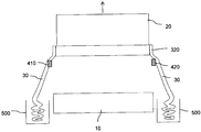
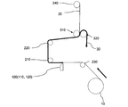
- FIG. 1 It is explanatory drawing which shows an example of the flow which manufactures a polarizing film from a polarizer original fabric. It is a side perspective view showing the edge cutting separation device of the optical film concerning the embodiment of the present invention. It is a front view showing the edge part cutting separation device of the optical film which concerns on embodiment of this invention. It is a side view which represents typically the edge cutting
- FIGS. 2 to 4 are side perspective views and front views showing an optical film edge cutting/separating device for cutting and separating an optical film body according to an embodiment of the present invention and unnecessary edges at both ends in the width direction thereof. It is a side view showing typically.
- the unusable edges (also referred to as ears) at both ends of the optical film in the width direction cannot be used for the product. Therefore, the unnecessary edges at the both ends of the optical film in the width direction are cut by the cutting portion. .. After cutting, collect unwanted edges and discard. In the present embodiment, this cutting process is performed before the swelling bath A, for example, in the series of steps shown in FIG.
- the roll-shaped optical film original fabric 10 is fed out from the original fabric roller in the film conveying direction.
- a cutting unit 100 is provided in the conveyance path of the optical film, and cuts unnecessary edges at both ends in the width direction of the optical film that cannot be used as a product.
- the cutting unit 100 includes two cutters 110 and 120.
- the cutters 110 and 120 are provided at positions that are separated from the outer edge of the optical film 10 in the width direction by a predetermined distance inward.
- the cutters 110 and 120 are provided below the optical film 10 in FIGS. 2 and 4, they may be provided above the optical film 10. Since the blades of the cutters 110 and 120 come into contact with the optical film 10, the optical film 10 is transported and unnecessary portions up to a predetermined distance from the outer edge in the width direction are cut by the blades of the cutters 110 and 120. ..
- the cutters 110 and 120 can cut the optical film, commercially available ones may be used.
- the regions of a predetermined width at both ends in the width direction of the optical film 10 are cut as unnecessary edge portions 30.
- a plurality of guide rollers 210 and 220 are provided on the downstream side of the cutting unit 100 in the film transport direction. By the guide rollers 210 and 220, both the cut optical film body 20 and the unnecessary edge portion 30 are guided to the pair of nip rollers 310 and 320 along the film transport direction.
- a pair of nip rollers 310 and 320 are provided downstream of the guide rollers 210 and 220 in the film transport direction.
- the pair of nip rollers 310 and 320 are composed of a driving side nip roller 310 and a driven side nip roller 320.
- the drive-side nip roller 310 is a roller that is rotationally driven by a drive motor or the like, and is arranged, for example, on the upstream side of the driven-side nip roller 320 in the film transport direction.
- the driven-side nip roller 320 is a free roller that rotates by being driven by the driving-side nip roller 310, and is arranged on the downstream side of the driving-side nip roller 310 in the film transport direction.
- the drive-side nip roller 310 and the driven-side nip roller 320 may be arranged in opposite positions, or the drive-side nip roller and the driven-side nip roller may be arranged so as to be orthogonal to the film transport direction (up and down in FIG. 4).
- the nip rollers 310 and 320 are disposed so as to sandwich both the optical film body 20 and the unnecessary edge portion 30 conveyed by the guide rollers 210 and 220 after the unnecessary edge portion 30 is cut by the cutters 110 and 120. There is. Then, the optical film body 20 and the unnecessary edge portion 30 are conveyed in different directions after passing through the nip rollers 310 and 320. As a result, the unnecessary edge portion 30 is separated from the optical film body 20.
- the remaining part after the unnecessary edge 30 is cut off from the optical film 10 becomes the optical film main body 20 used as a product.
- the optical film body 20 used as a product, it is preferable to hang the optical film body 20 on the driving side nip roller 310 and the unnecessary edge portion 30 on the driven side nip roller 320.
- the unnecessary edge portion 30 and the optical film main body 20 are not immediately separated, and are conveyed together to the nip rollers 310 and 320 on the downstream side in the film conveying direction. Therefore, by separating the optical film main body 20 and the unnecessary edge portion 30 after passing through the nip rollers 310 and 320, the tension of the unnecessary edge portion 30 between the cutters 110 and 120 and the nip rollers 310 and 320 is reduced.
- the tension of the optical film body 20 can be made the same, and the transport of the film can be stabilized.
- the optical film main body 20 is guided upward and the unnecessary edge portion 30 is guided downward so as to separate the both.
- a guide roller 240 is arranged downstream of the pair of nip rollers 310 and 320 in the film transport direction, and the guide roller 240 transports only the optical film main body 20 downstream in the film transport direction.
- the guide roller 240 is arranged above the pair of nip rollers 310 and 320.
- the position to be arranged is not limited to this. Since the unnecessary edge portion 30 is hooked on the driven nip roller 320, the unnecessary edge portion 30 is naturally dropped and collected in the edge portion recovery portion 500 such as a trash can.
- the unnecessary edge portions 30 spontaneously fall and are collected in the edge portion collecting section 500, but for example, the unnecessary edge portions 30 can be wound up on a roll and then discarded.
- the present invention is not limited to guiding the optical film main body 20 upward and the unnecessary edge portion 30 downward, and guides the optical film main body 20 and the unnecessary edge portion 30 in different directions. If so, the direction to guide is free.
- a pair of guide members (for example, a PP band (polypropylene band)) 410, 420 is provided below a nip roller 310, 320 on a support frame (not shown) that supports the nip roller 310, 320, as shown in FIG. is set up.
- the pair of guide members 410, 420 are installed so that the extending direction of the pair of guide members 410, 420 forms an angle with the longitudinal direction (axial direction) of the nip rollers 310, 320 (not in parallel). ..
- the pair of guide members 410 and 420 are installed so that the extending direction thereof is orthogonal to the longitudinal direction of the nip rollers 310 and 320.
- the guide members 410 and 420 are arranged below the nip rollers 310 and 320, respectively, and are arranged at the longitudinal ends of the nip rollers 310 and 320, respectively.
- the optical film body 20 that has passed through the nip rollers 310 and 320 and the unnecessary edge portion 30 are guided in different directions.
- the unnecessary edge portions 30 are hooked on the pair of guide members 410 and 420, respectively, and separated from the optical film body 20.
- the pair of guide members 410 and 420 are unnecessary so that the unnecessary edge portion 30 does not interfere with surrounding rolls or pass lines when the unnecessary edge portion 30 that has been cut is separated from the optical film body 20.
- the edge portion 30 is guided outward in the width direction of the optical film 10. That is, as shown in FIG. 3, the unnecessary edge portion 30 separated from the optical film body 20 is guided to the outer side in the width direction of the film by the guide members 410 and 420. If the guide members 410 and 420 are not provided, the separated unnecessary edge portion 30 may contact, for example, the original roller, the guide roller 230, the optical film 10 conveyed by the guide roller 230, or the like.
- the members 410, 420 prevent the separated unwanted edges 30 from contacting them.
- the PP band as the guide members 410 and 420 may have a plate shape or a thin rod shape.
- a material for the guide members 410 and 420 metal, resin, or the like may be used.
- the guide members 410 and 420 may be, for example, transport rollers that transport the unnecessary edge portion 30 that has been cut.
- the optical film 10 is a polarizer. Specifically, it is a raw film such as a polyvinyl alcohol film.
- the thickness of the polarizer is 1 to 100 ⁇ m, preferably 1 to 20 ⁇ m.
- the roll-shaped optical film 10 is supported by a film supporting portion (not shown) and is fed out in the film transport direction.
- the cutters 110 and 120 included in the cutting unit 100 cut the optical film 10 into an optical film main body 20 and an unnecessary edge portion 30 which are used later in a product.
- both the cut optical film body 20 and the unnecessary edge portion 30 are conveyed to the nip rollers 310 and 320 through the plurality of guide rollers 210 and 220 toward the downstream side in the film conveyance direction.
- the nip rollers 310 and 320 sandwich both the conveyed optical film body 20 and the unnecessary edge portion 30, and hang the optical film body 20 on the driving side nip roller 310 and the unnecessary edge portion 30 on the driven side nip roller 320. In this way, the unnecessary edge portion 30 is separated from the optical film main body 20, and the optical film main body 20 and the unnecessary edge portion 30 are respectively conveyed to the downstream side.
- the optical film main body 20 is guided upward and the unnecessary edge portion 30 is guided downward. Furthermore, the PP band which is the guide members 410 and 420 guides the unnecessary edge portion 30 to the outside in the width direction of the optical film. As a result, the unnecessary edge portion 30 is conveyed to the outer side in the width direction of the optical film and in the direction of the natural fall, and is collected in the edge portion recovery unit 500 such as a dustbin.
- the present invention is not limited to the embodiments described above, and various modifications are included.
- the above-described embodiments have been described in detail in order to explain the present invention in an easy-to-understand manner, and are not necessarily limited to those having all the configurations described.
- a part of the configuration of one embodiment can be replaced with the configuration of another embodiment, and the configuration of another embodiment can be added to the configuration of one embodiment.
- the present invention is preferably used for manufacturing a long optical film.
Landscapes
- Physics & Mathematics (AREA)
- General Physics & Mathematics (AREA)
- Optics & Photonics (AREA)
- Life Sciences & Earth Sciences (AREA)
- Forests & Forestry (AREA)
- Engineering & Computer Science (AREA)
- Mechanical Engineering (AREA)
- Polarising Elements (AREA)
- Details Of Cutting Devices (AREA)
Abstract
Description
しかしながら、特許文献1の装置では、切断した複数のフィルムをそれぞれ異なるガイドローラを使って分離しているので、各フィルムにかかる張力が異なり、切断した後のフィルムの搬送が安定しない虞がある。特に光学フィルムは、薄いフィルムであるので、少しの張力の違いで、フィルムがばたついて安定しない。その結果、幅方向に隣り合う一方のフィルムが他方のフィルムに乗り上げてフィルム同士がくっつく虞がある。
なお、上記の説明で用いた特許文献1、2に記載の部材の符号は、後述する本発明の実施形態で用いる符号と区別するために括弧をつけて表している。
本発明によれば、切断部で不要な縁部を切断した後に、光学フィルム本体及び不要な縁部の双方をニップローラで挟み、その後に不要な縁部を光学フィルム本体から分離する。したがって、不要な縁部の分離をニップローラを通過した後に行うことにより、切断部とニップローラとの間において、不要な縁部の張力と光学フィルム本体の張力とを同じにすることができ、フィルムの搬送を安定させることができる。つまり、ニップローラでテンションカットされるので、ニップローラを通過した後に光学フィルム本体と不要な縁部とが分離されても、切断部とニップローラとの間のフィルムの搬送を安定させることができる。
また、ニップローラを通過した後の光学フィルム本体と不要な縁部とは、それぞれ、所望の方向に案内することができるので、パスラインの設計自由度を向上させることができる。
上記の好ましい構成によれば、光学フィルム本体が駆動側ニップローラ及び従動側ニップローラのうちの一方に掛けられ、不要な縁部が駆動側ニップローラ及び従動側ニップローラのうちの他方に掛けられるので、光学フィルム本体と不要な縁部とを別々の方向に搬送することができ、ニップローラを通過後のパスラインの設計自由度をより向上させやすい。
上記の好ましい構成によれば、光学フィルム本体が駆動側ニップローラに掛けられ、不要な縁部が従動側ニップローラに掛けられるので、光学フィルム本体と不要な縁部とをそれぞれ異なる方向に搬送することができ、ニップローラを通過後のパスラインの設計自由度をより向上させやすい。
上記の好ましい構成によれば、不要な縁部が従動側ニップローラに掛けられ、下方に案内されるので、不要な縁部を自然落下させることができる。その結果、不要な縁部を回収するためのガイドローラ等が不要となり、低コストで不要な縁部を回収できる。
上記の好ましい構成によれば、不要な縁部を光学フィルムの幅方向外側に案内する案内部材を設置するので、不要な縁部を光学フィルムの幅方向外側に切り離して廃棄することができる。したがって、例えばニップローラの下方において光学フィルムが搬送されている場合等であっても、周囲の光学フィルムなどに切り離された不要な縁部が接触することなく、不要な縁部をゴミ箱等に案内することができる。
図2~図4に示すように、ロール状の光学フィルム原反10が原反ローラからフィルム搬送方向に繰り出される。光学フィルムの搬送経路には、切断部100が設けられ、製品に使えない光学フィルムの幅方向両端部における不要な縁部を切断する。
切断部100のフィルム搬送方向下流側に、複数のガイドローラ210、220が設けられている。このガイドローラ210、220により、切断された光学フィルム本体20及び不要な縁部30の双方が、フィルム搬送方向に沿って一対のニップローラ310、320まで案内される。
一対のニップローラ310、320が、ガイドローラ210、220のフィルム搬送方向下流側に設けられている。また、一対のニップローラ310、320は、駆動側ニップローラ310と従動側ニップローラ320とから構成されている。駆動側ニップローラ310は、駆動モータ等で回転駆動されるローラであり、例えば従動側ニップローラ320よりもフィルム搬送方向上流側に配置される。従動側ニップローラ320は、駆動側ニップローラ310に従動して回動するフリーローラであり、駆動側ニップローラ310よりもフィルム搬送方向下流側に配置される。ただし、駆動側ニップローラ310及び従動側ニップローラ320の配置位置は逆でもよいし、駆動側ニップローラと従動側ニップローラとがフィルム搬送方向に直交するように(図4における上下に)配置されてもよい。
一対の案内部材(例えばPPバンド(ポリプロピレンバンド))410、420が、図2に示すように、ニップローラ310、320の下方に位置において、ニップローラ310、320を支持する支持フレーム(図示せず)に設置されている。この一対の案内部材410、420の延びる方向がニップローラ310、320の長手方向(軸方向)と角度を成すように(平行にはならないように)、一対の案内部材410、420は設置されている。好ましくは、一対の案内部材410、420の延びる方向がニップローラ310、320の長手方向に直交するように設置される。案内部材410、420は、それぞれ、ニップローラ310、320の下方に配置され、且つニップローラ310、320の長手方向端部に配置されている。
20 光学フィルム本体
30 不要な縁部
100 切断部
110 カッター(切断部)
120 カッター(切断部)
210、220、230、240 ガイドローラ
310 駆動側ニップローラ(ニップローラ)
320 従動側ニップローラ(ニップローラ)
410、420 案内部材
500 縁部回収部
Claims (6)
- 長尺状の光学フィルムの幅方向両端部における不要な縁部を切断して光学フィルム本体と不要な縁部とする切断部と、
前記切断部の下流側に配置され、前記光学フィルム本体及び前記不要な縁部の双方を挟む一対のニップローラと、を有し、
前記光学フィルム本体及び前記不要な縁部が前記ニップローラを通過した後、前記光学フィルム本体と不要な縁部とを分離する、
光学フィルムの縁部切断分離装置。 - 前記一対のニップローラが駆動側ニップローラと従動側ニップローラとから構成され、
前記光学フィルム本体が前記駆動側ニップローラ及び前記従動側ニップローラのうちの一方に掛けられ、前記不要な縁部が前記駆動側ニップローラ及び前記従動側ニップローラの他方に掛けられる、
請求項1に記載の光学フィルムの縁部切断分離装置。 - 前記光学フィルム本体が前記駆動側ニップローラに掛けられ、前記不要な縁部が前記従動側ニップローラに掛けられる、
請求項2に記載の光学フィルムの縁部切断分離装置。 - 前記不要な縁部が下方に案内される、
請求項3に記載の光学フィルムの縁部切断分離装置。 - 前記不要な縁部を前記光学フィルムの幅方向外側に案内する案内部材を有する、
請求項1から4のいずれか1項に記載の光学フィルムの縁部切断分離装置。 - 前記光学フィルムは偏光子である、
請求項1から5のいずれか1項に記載の光学フィルムの縁部切断分離装置。
Priority Applications (2)
| Application Number | Priority Date | Filing Date | Title |
|---|---|---|---|
| KR1020217007251A KR102772777B1 (ko) | 2018-12-28 | 2019-12-09 | 광학 필름의 에지부 절단 분리 장치 |
| JP2020563025A JP7518768B2 (ja) | 2018-12-28 | 2019-12-09 | 光学フィルムの縁部切断分離装置 |
Applications Claiming Priority (2)
| Application Number | Priority Date | Filing Date | Title |
|---|---|---|---|
| CN201811620228.5 | 2018-12-28 | ||
| CN201811620228.5A CN111377291B (zh) | 2018-12-28 | 2018-12-28 | 光学膜的端缘部切断分离装置 |
Publications (1)
| Publication Number | Publication Date |
|---|---|
| WO2020137486A1 true WO2020137486A1 (ja) | 2020-07-02 |
Family
ID=71127990
Family Applications (1)
| Application Number | Title | Priority Date | Filing Date |
|---|---|---|---|
| PCT/JP2019/048066 Ceased WO2020137486A1 (ja) | 2018-12-28 | 2019-12-09 | 光学フィルムの縁部切断分離装置 |
Country Status (4)
| Country | Link |
|---|---|
| JP (1) | JP7518768B2 (ja) |
| KR (1) | KR102772777B1 (ja) |
| CN (1) | CN111377291B (ja) |
| WO (1) | WO2020137486A1 (ja) |
Citations (5)
| Publication number | Priority date | Publication date | Assignee | Title |
|---|---|---|---|---|
| JPS4865860U (ja) * | 1971-11-30 | 1973-08-21 | ||
| JPS4872587U (ja) * | 1971-12-13 | 1973-09-11 | ||
| JPS6377697A (ja) * | 1986-09-19 | 1988-04-07 | 東レ株式会社 | 熱可塑性樹脂フイルムのエツジトリミング装置 |
| JPH07149466A (ja) * | 1993-11-26 | 1995-06-13 | Diafoil Co Ltd | 耳部フイルム引取り方法 |
| CN209455795U (zh) * | 2018-12-28 | 2019-10-01 | 日东电工株式会社 | 光学膜的端缘部切断分离装置 |
Family Cites Families (8)
| Publication number | Priority date | Publication date | Assignee | Title |
|---|---|---|---|---|
| CH103660A (fr) * | 1923-03-03 | 1924-04-01 | Bobst Fils Sa J | Dispositif pour l'évacuation des rognures dans les machines munies de cisailles circulaires pour couper le papier, le carton ou autres produits en feuilles. |
| US3156149A (en) * | 1962-09-26 | 1964-11-10 | Nat Distillers Chem Corp | Apparatus for trimming and winding sheeted materials |
| JP5474869B2 (ja) | 2010-09-03 | 2014-04-16 | 日東電工株式会社 | 偏光膜を有する積層体ストリップロールの製造方法 |
| JP5617608B2 (ja) | 2010-12-24 | 2014-11-05 | 日本ゼオン株式会社 | フィルム耳の切取回収装置、長尺の光学フィルムの製造方法、及びフィルム耳の巻回体の製造方法 |
| JP5984715B2 (ja) * | 2013-02-27 | 2016-09-06 | 株式会社島精機製作所 | シート材の耳端排出装置 |
| CN206455740U (zh) * | 2017-02-15 | 2017-09-01 | 昆山地博光电材料有限公司 | 一种塑料薄膜切边余料收集引导装置 |
| CN207156291U (zh) * | 2017-08-17 | 2018-03-30 | 江苏和和新材料股份有限公司 | 一种高速流延机的胶膜收卷装置 |
| KR101928341B1 (ko) * | 2018-07-10 | 2018-12-12 | 김형목 | 사이드 스크랩 인출 가이드 장치 |
-
2018
- 2018-12-28 CN CN201811620228.5A patent/CN111377291B/zh active Active
-
2019
- 2019-12-09 WO PCT/JP2019/048066 patent/WO2020137486A1/ja not_active Ceased
- 2019-12-09 JP JP2020563025A patent/JP7518768B2/ja active Active
- 2019-12-09 KR KR1020217007251A patent/KR102772777B1/ko active Active
Patent Citations (5)
| Publication number | Priority date | Publication date | Assignee | Title |
|---|---|---|---|---|
| JPS4865860U (ja) * | 1971-11-30 | 1973-08-21 | ||
| JPS4872587U (ja) * | 1971-12-13 | 1973-09-11 | ||
| JPS6377697A (ja) * | 1986-09-19 | 1988-04-07 | 東レ株式会社 | 熱可塑性樹脂フイルムのエツジトリミング装置 |
| JPH07149466A (ja) * | 1993-11-26 | 1995-06-13 | Diafoil Co Ltd | 耳部フイルム引取り方法 |
| CN209455795U (zh) * | 2018-12-28 | 2019-10-01 | 日东电工株式会社 | 光学膜的端缘部切断分离装置 |
Also Published As
| Publication number | Publication date |
|---|---|
| JPWO2020137486A1 (ja) | 2021-11-18 |
| CN111377291B (zh) | 2024-11-19 |
| JP7518768B2 (ja) | 2024-07-18 |
| CN111377291A (zh) | 2020-07-07 |
| KR20210107615A (ko) | 2021-09-01 |
| KR102772777B1 (ko) | 2025-02-27 |
Similar Documents
| Publication | Publication Date | Title |
|---|---|---|
| JP6338642B2 (ja) | ハンドリングタブを連続的なガラスリボンに貼り付ける方法および装置 | |
| JP5617608B2 (ja) | フィルム耳の切取回収装置、長尺の光学フィルムの製造方法、及びフィルム耳の巻回体の製造方法 | |
| US8582863B2 (en) | Winding device and assembly comprising a winding device | |
| JP7148837B2 (ja) | ガラスロールの製造方法 | |
| RU2010118503A (ru) | Пленки с усиленными краями и кромками | |
| CN106413861B (zh) | 中空纤维膜片状物的制造方法及制造装置以及中空纤维膜片状物 | |
| CN209455795U (zh) | 光学膜的端缘部切断分离装置 | |
| JP5736754B2 (ja) | 中空糸膜シート状物の製造方法及び製造装置 | |
| WO2020137486A1 (ja) | 光学フィルムの縁部切断分離装置 | |
| TWI621488B (zh) | 網切斷方法及網切斷裝置 | |
| CN103213867A (zh) | 宽幅卷材分切装置及分切方法 | |
| KR101688969B1 (ko) | 광학필름 클리닝장치 | |
| JP5480315B2 (ja) | ウエブ切断方法、及びウエブ切断装置 | |
| CN106061720B (zh) | 放泄绳贴附装置及贴附方法 | |
| JP2020001855A (ja) | 通紙装置、フィルム製造装置及び微多孔膜製造装置、フィルム通し方法並びに微多孔膜製造方法 | |
| JP2018034145A (ja) | 洗浄装置 | |
| CN218370719U (zh) | 用于卷绕光学膜的毛边和抽丝的装置以及光学膜的转移收集系统 | |
| CN108521770A (zh) | 用于胶合、处理和储存模切材料的方法 | |
| JP6324913B2 (ja) | ウエブ巻き取り方法、および、ウエブ巻き取り装置 | |
| KR20090123300A (ko) | 아이티오 필름 원단 절단기 | |
| JP7612080B2 (ja) | 光学フィルムの通紙方法 | |
| JP6514032B2 (ja) | タイヤ部材の製造方法および製造装置 | |
| JP2015003368A (ja) | トリミング装置、及び、光学フィルムの製造方法 | |
| CN117466023A (zh) | 用于卷绕毛边和抽丝的装置和方法以及转移收集系统 | |
| JP6470001B2 (ja) | 食品の包装材分離装置および包装材分離方法 |
Legal Events
| Date | Code | Title | Description |
|---|---|---|---|
| 121 | Ep: the epo has been informed by wipo that ep was designated in this application |
Ref document number: 19904192 Country of ref document: EP Kind code of ref document: A1 |
|
| ENP | Entry into the national phase |
Ref document number: 2020563025 Country of ref document: JP Kind code of ref document: A |
|
| ENP | Entry into the national phase |
Ref document number: 20217007251 Country of ref document: KR Kind code of ref document: A |
|
| NENP | Non-entry into the national phase |
Ref country code: DE |
|
| 122 | Ep: pct application non-entry in european phase |
Ref document number: 19904192 Country of ref document: EP Kind code of ref document: A1 |