WO2020137393A1 - 車両用視認装置 - Google Patents
車両用視認装置 Download PDFInfo
- Publication number
- WO2020137393A1 WO2020137393A1 PCT/JP2019/047365 JP2019047365W WO2020137393A1 WO 2020137393 A1 WO2020137393 A1 WO 2020137393A1 JP 2019047365 W JP2019047365 W JP 2019047365W WO 2020137393 A1 WO2020137393 A1 WO 2020137393A1
- Authority
- WO
- WIPO (PCT)
- Prior art keywords
- fixing
- rotating
- contact
- vehicle
- rigidity
- Prior art date
- Legal status (The legal status is an assumption and is not a legal conclusion. Google has not performed a legal analysis and makes no representation as to the accuracy of the status listed.)
- Ceased
Links
Images



Classifications
-
- B—PERFORMING OPERATIONS; TRANSPORTING
- B60—VEHICLES IN GENERAL
- B60R—VEHICLES, VEHICLE FITTINGS, OR VEHICLE PARTS, NOT OTHERWISE PROVIDED FOR
- B60R1/00—Optical viewing arrangements; Real-time viewing arrangements for drivers or passengers using optical image capturing systems, e.g. cameras or video systems specially adapted for use in or on vehicles
- B60R1/02—Rear-view mirror arrangements
- B60R1/06—Rear-view mirror arrangements mounted on vehicle exterior
-
- B—PERFORMING OPERATIONS; TRANSPORTING
- B60—VEHICLES IN GENERAL
- B60R—VEHICLES, VEHICLE FITTINGS, OR VEHICLE PARTS, NOT OTHERWISE PROVIDED FOR
- B60R1/00—Optical viewing arrangements; Real-time viewing arrangements for drivers or passengers using optical image capturing systems, e.g. cameras or video systems specially adapted for use in or on vehicles
- B60R1/02—Rear-view mirror arrangements
- B60R1/06—Rear-view mirror arrangements mounted on vehicle exterior
- B60R1/062—Rear-view mirror arrangements mounted on vehicle exterior with remote control for adjusting position
- B60R1/07—Rear-view mirror arrangements mounted on vehicle exterior with remote control for adjusting position by electrically powered actuators
- B60R1/074—Rear-view mirror arrangements mounted on vehicle exterior with remote control for adjusting position by electrically powered actuators for retracting the mirror arrangements to a non-use position alongside the vehicle
Definitions
- a vehicle visual recognition device is the vehicle visual identification device according to the first aspect of the present invention, wherein the rigidity lowering portion reduces the rigidity on the contact portion side of at least one of the inhibition portion and the contact portion.
- the rigidity is reduced as compared with the rigidity on the non-contact part side of at least one of the prohibition part and the contact part.
- the rotating body is supported by the support body on the vehicle body side, and the visual recognition mechanism is provided on the rotating body, and the visual recognition mechanism assists the visual recognition of the occupant. Further, the rotating body is rotated and stored. Further, the prohibiting portion of the support body and the contact portion of the rotating body are brought into contact with each other, and the rotation of the rotating body is prohibited.
- At least one of the prohibition portion and the contact portion is provided with a rigidity lowering portion, and the rigidity reduction portion reduces the rigidity of at least one of the prohibition portion and the contact portion. Therefore, at least one of the inhibition portion and the contact portion can release the contact force between the inhibition portion and the contact portion, and the damage of the inhibition portion and the contact portion can be suppressed.
- the contact portion when the forbidden portion and the contact portion are brought into contact with each other, the contact portion is moved toward the rotary body rotation axis direction. Therefore, the contact force between the prohibition portion and the contact portion can be reduced, and damage to the prohibition portion and the contact portion can be effectively suppressed.
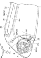
- FIG. 1 is an exploded perspective view of a vehicle door mirror device according to an embodiment of the present invention, which is seen obliquely from above and behind a vehicle.
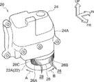
- FIG. 3 is a perspective view of the stay of the vehicle door mirror device according to the embodiment of the present invention, as seen obliquely from above and behind the vehicle.
- FIG. 1 is a perspective view of a storage device and a main body of a vehicle door mirror device according to an embodiment of the present invention, as viewed from diagonally below the vehicle rear.
- FIG. 1 is a perspective view of a storage device for a vehicle door mirror device according to an embodiment of the present invention, seen from diagonally above the front of a vehicle.
- the predetermined number of fixed slits 18 are arranged in the vertical direction, and the predetermined number of the fixed slits 18 gradually increase in extension dimension (dimension in the circumferential direction of the fixing hole 14) from the upper side to the lower side.
- the fixing slit 18 reduces the rigidity of the first fixing portion 16A and the second fixing portion 16B, and the rigidity of the first fixing portion 16A and the second fixing portion 16B depends on the fixing slit 18 from the upper side to the lower side. It is getting smaller and smaller.
- a storage device 20 (see FIGS. 3 and 4) as a storage mechanism is supported by the support protrusion 12A of the stay 12.
- the storage device 20 is provided with a substantially cylindrical stand 22 as a support portion that constitutes a support body, and a substantially cylindrical fixed cylinder 22A is coaxially provided at a lower end portion of the stand 22. ..
- the fixed cylinder 22A is coaxially inserted into the fixing hole 14 of the support protrusion 12A and fixed to the support protrusion 12A, whereby the storage device 20 is supported by the stay 12.
- a cylindrical support shaft 22B (see FIG. 5) is integrally formed at the center of the upper surface of the fixed cylinder 22A, and the support shaft 22B is projected upward and arranged coaxially with the fixed cylinder 22A. ing.
- a plurality of (for example, two) long curved columnar limiting protrusions are integrally formed as a limiting portion on the outer side in the radial direction of the support shaft 22B. , And is extended in the circumferential direction of the fixed cylinder 22A.
- the plurality of limiting convex portions are arranged at equal intervals in the circumferential direction of the fixed cylinder 22A, and the end faces of the limiting convex portion on the forward tilt direction side and the storage direction side are arranged parallel to the radial direction of the fixed cylinder 22A. At the same time, it is inclined toward the inner side in the circumferential direction of the fixed cylinder 22A of the limiting projection as it goes upward.
- a drive body 24 that constitutes a rotating body is supported by the stand 22, and the drive body 24 is urged downward with respect to the stand 22 while the support shaft 22B is inserted.
- the drive body 24 is rotated with respect to the stand 22 about the support shaft 22B in the storage direction and the forward tilt direction.
- a resin case 24A as a rotating member is provided on the outer periphery of the driving body 24.
- a long curved plate-shaped turning protrusion 26 (turning body side stopper) as an abutting part is integrally formed around the vehicle front side of the fixed cylinder 22A. , And is extended in the circumferential direction of the fixed cylinder 22A (the rotational circumferential direction of the driving body 24).
- the storage protrusion side and the forward tilting side portions of the rotation protrusion 26 are formed as a first rotation portion 26A and a second rotation portion 26B (see FIGS. 5, 6A and 6B), respectively.
- the first rotation surface 26C and the second rotation surface 26D are inclined toward the inner side in the circumferential direction of the fixed cylinder 22A of the rotation protrusion 26 as they go downward, and the first rotation surface 26C and the second rotation surface 26D are rotated.
- the inclination angle of the moving surface 26D with respect to the lower side is smaller than the inclination angle of the first fixing surface 16C and the second fixing surface 16D of the fixing protrusion 16 of the stay 12 with respect to the upper side.
- Upper ends of the first rotating surface 26C and the second rotating surface 26D are curved in a concave shape, and lower ends of the first rotating surface 26C and the second rotating surface 26D are curved in a convex shape. ..
- the first rotating portion 26A and the second rotating portion 26B are each formed with a predetermined number (four in this embodiment) of rotating slits 28 having a rectangular cross section as rigidity lowering portions. Penetrates the first rotating portion 26A and the second rotating portion 26B in the radial direction of the fixed cylinder 22A.
- the rotating slit 28 extends in the circumferential direction of the fixed cylinder 22A, and the rotating slits 28 of the first rotating portion 26A and the second rotating portion 26B are opened to the storage direction side and the forward tilting side, respectively. ing.
- Each corner between the bottom surface (the inner surface of the fixed cylinder 22A in the radial direction) and the upper surface, the lower surface, and the extended end surface (the inner surface of the rotary projection 26 in the circumferential direction of the fixed cylinder 22A) of the rotary slit 28 is curved in a concave shape. Further, each corner between the extended end surface of the rotary slit 28 and the upper and lower surfaces is concavely curved. That is, each of the corners of the rotary slit 28 is rounded.
- a main body 30 (see FIGS. 3 and 5) forming a rotating body is supported by the drive body 24 of the storage device 20.
- the main body 30 is provided with a resin visor 32 as a cover, and the visor 32 is provided with a visor body 32A as a main body member.
- An inner portion in the vehicle width direction of the visor body 32A is fixed to the driving body 24 on the vehicle front side, whereby the visor 32 is supported by the driving body 24, so that the main body portion 30 is supported by the driving body 24.
- the main body portion 30 is arranged in a standing position (a deployed position shown by a solid line in FIG. 5), and the main body portion 30 is projected (stretched) to the outside of the stay 12 in the vehicle width direction.
- a substantially rectangular parallelepiped storage chamber 34 is formed in the vehicle rear side portion of the visor body 32A, and the storage chamber 34 is open to the vehicle rear side.
- a substantially rectangular plate-shaped mirror 36 as a visual recognition mechanism is housed and supported in a housing chamber 34 of the visor body 32A, and a mirror surface 36A (light reflecting surface on the back side) of the mirror 36 is directed to the vehicle rear side. There is. Therefore, the mirror 36 assists the occupant (particularly the driver) of the vehicle to visually recognize the rear side of the vehicle.
- the main body portion 30 is integrated with the driving body 24 in a standing position (indicated by a solid line in FIG. 5) by driving the storage device 20 or inputting an external force to the main body portion 30 (particularly, the visor 32).
- the main body portion 30 including the mirror 36
- the storage position the rear storage position, which is indicated by a two-dot chain line in FIG. 5. It is placed at the position shown) and stored (post-stored).
- the main body 30 rotates integrally with the driving body 24 from the storage position in the forward tilt direction (vehicle front side and vehicle width direction outer side).
- the main body 30 (including the mirror 36) is returned to the standing position and stands up.
- the rotation convex portion of the driving body 24 is brought into contact with the end surface on the storage direction side of the limiting convex portion of the stand 22, so that the main body portion 30 is tilted forward. Rotation in the direction is restricted.
- the main body portion 30 is integrated with the driving body 24 from the standing position in the forward tilting direction (vehicle front side and vehicle width direction).
- the main body portion 30 including the mirror 36
- the main body portion 30 is arranged at the forward tilt position (the front storage position, the position shown by the one-dot chain line in FIG. 5), and the front tilt (front storage) To be done.
- the turning convex portion of the drive body 24 is opposed to the lower biasing force of the drive body 24 with respect to the stand 22. Riding on the limiting convex portion of 22. Therefore, when the body portion 30 is arranged in the forward tilt direction side of the standing position (see FIG. 6B), when the body portion 30 is arranged in the range from the standing position to the storage position (see FIG. 6A). In contrast, the driving body 24 and the main body 30 are moved upward with respect to the stand 22.
- the fixing slits 18 of the first fixing portion 16A and the second fixing portion 16B of the fixing protrusion 16 reduce the rigidity of the first fixing portion 16A and the second fixing portion 16B, respectively, and the first protrusion of the turning protrusion 26
- the rotating slits 28 of the moving portion 26A and the second rotating portion 26B reduce the rigidity of the first rotating portion 26A and the second rotating portion 26B, respectively.
- the first fixing portion 16A and the first rotating portion 26A can release the contact force (particularly the impact force) between the first fixing surface 16C and the first rotating surface 26C, and the first fixing portion 16A and the first rotating portion.
- the damage (particularly breakage) of the portion 26A can be suppressed, and the contact noise between the first fixed surface 16C and the first rotating surface 26C can be reduced.
- the second fixing portion 16B and the second rotating portion 26B can release the abutting force (especially impact force) between the second fixing surface 16D and the second rotating surface 26D, and the second fixing portion 16B and the second rotating portion.
- the damage (particularly breakage) of the portion 26B can be suppressed, and the contact noise between the second fixed surface 16D and the second rotating surface 26D can be reduced.
- the predetermined size of the fixed slits 18 in the first fixing portion 16A and the second fixing portion 16B is gradually increased in the extending dimension from the upper side to the lower side, and the first fixing portion 16A and the second fixing portion 16B.
- the rigidity of the lower side portion is lower than the rigidity of the upper side portions of the first fixing portion 16A and the second fixing portion 16B, respectively.
- the predetermined number of the rotary slits 28 in the first rotary portion 26A and the second rotary portion 26B are gradually increased in the extension dimension from the upper side to the lower side, respectively.
- the rigidity of the lower portion of the second rotating portion 26B is lower than the rigidity of the upper portions of the first rotating portion 26A and the second rotating portion 26B, respectively.
- the lower portion of the second fixing surface 16D of the second fixing portion 16B and the lower end of the second rotating surface 26D of the second rotating portion 26B come into contact with each other.
- the lower portion (contact portion side) of the second fixing portion 16B and the lower portion (contact portion side) of the second rotating portion 26B make a second rotation with the second fixing surface 16D.
- the contact force (particularly impact force) with the surface 26D can be released, damage to the second fixing portion 16B and the second rotating portion 26B (particularly breakage) can be appropriately suppressed, and the second fixing surface 16D and the second fixing surface 16D
- the contact noise with the rotating surface 26D can be appropriately reduced.
- each corner between the bottom surface and the upper surface, the lower surface and the extended end surface of the fixed slit 18 and each corner between the extended end surface and the upper surface and the lower surface of the fixed slit 18 are concavely curved.
- the corners between the bottom surface and the upper surface, the lower surface and the extending end surface of 28 and the corners between the extending end surface and the upper surface and the lower surface of the rotating slit 28 are concavely curved.
- the first rotation surface 26C can be moved upward (to the rotation axis direction of the drive body 24) by the guide by the first fixing surface 16C against the lower biasing force of the drive body 24 with respect to the stand 22.
- the body 24 and the main body 30 can be moved upward, and the contact force between the first fixed surface 16C and the first rotary surface 26C can be reduced (absorbed) by the upward movement of the drive body 24 and the main body 30.
- the contact force between the surface 16D and the second rotation surface 26D can be reduced (absorbed), the damage (particularly, breakage) of the second fixing portion 16B and the second rotation portion 26B can be effectively suppressed, and the second fixing The contact noise between the surface 16D and the second rotation surface 26D can be effectively reduced.
- the predetermined dimension of the fixed slits 18 in the first fixing portion 16A and the second fixing portion 16B is gradually reduced in the extending dimension from the lower side to the upper side, and the first fixing portion 16A and the second fixing portion 16B.
- the rigidity of the upper part of is higher than the rigidity of the lower parts of the first fixing portion 16A and the second fixing portion 16B, respectively.
- the predetermined size of the rotary slits 28 in the first rotary portion 26A and the second rotary portion 26B is gradually reduced in the extension dimension from the lower side to the upper side.
- the rigidity of the upper part of the second rotating part 26B is higher than the rigidity of the lower part of the first rotating part 26A and the second rotating part 26B.
- the main body 30 is rotated to the retracted position, and the lower portion of the first fixing surface 16C of the first fixing portion 16A and the lower end of the first rotating surface 26C of the first rotating portion 26A come into contact with each other.
- the upper portion (non-contact portion side) of the first fixing portion 16A and the upper portion (non-contact portion side) of the first rotating portion 26A make the first rotation with the first fixing surface 16C.
- the contact force (especially impact force) with the surface 26C can be appropriately received, and the rotation of the main body 30 from the storage position to the storage direction can be appropriately prohibited.
- the lower portion of the second fixing surface 16D of the second fixing portion 16B and the lower end of the second rotating surface 26D of the second rotating portion 26B come into contact with each other.
- the upper part (non-contact part side) of the second fixing part 16B and the upper part (non-contact part side) of the second rotating part 26B are rotated with the second fixing surface 16D.
- the contact force (particularly the impact force) with the surface 26D can be appropriately received, and the rotation of the main body 30 from the forward tilted position to the forward tilted direction can be appropriately prohibited.
- the fixing slit 18 is provided in the upper portion of the first fixing portion 16A and the second fixing portion 16B, and the rotating slit is provided in the upper portion of the first rotating portion 26A and the second rotating portion 26B. 28 is provided.
- at least one of the structure in which the fixing slit 18 is not provided in the upper portion of the first fixing portion 16A and the structure in which the rotating slit 28 is not provided in the upper portion of the first rotating portion 26A may be adopted.
- At least one of a configuration in which the fixed slit 18 is not provided in the upper portion of the portion 16B and a configuration in which the rotation slit 28 is not provided in the upper portion of the second rotation portion 26B may be adopted.
- the main body 30 is rotated to the retracted position, and the lower portion of the first fixing surface 16C of the first fixing portion 16A and the lower end of the first rotating surface 26C of the first rotating portion 26A come into contact with each other.
- at least one of the upper portion of the first fixing portion 16A and the upper portion of the first rotating portion 26A has a contact force (especially impact force) between the first fixing surface 16C and the first rotating surface 26C. ) Can be more appropriately received, and the rotation of the main body portion 30 from the storage position to the storage direction can be more appropriately prohibited.
- the fixing slits 18 of the first fixing portion 16A and the second fixing portion 16B are extended in the rotation circumferential direction of the driving body 24, and the first rotating portion 26A and the second rotating portion 26B are also included.
- the rotary slit 28 is extended in the circumferential direction of rotation of the driving body 24.
- the fixing slit 18 of at least one of the first fixing portion 16A and the second fixing portion 16B may be extended in a direction (for example, a vertical direction) other than the rotation circumferential direction of the driving body 24, and the first rotation portion 26A.
- at least one of the rotation slits 28 of the second rotation portion 26B may be extended in a direction (for example, a vertical direction) other than the rotation circumferential direction of the driving body 24.
- the fixing slit 18 is provided in the first fixing portion 16A and the second fixing portion 16B, and the turning slit 28 is provided in the first turning portion 26A and the second turning portion 26B.
- the fixing slit 18 may not be provided in the first fixing portion 16A or the rotating slit 28 may not be provided in the first rotating portion 26A, and the fixing slit 18 may be provided in the second fixing portion 16B.
- the rotation slit 28 may not be provided in the second rotation portion 26B.
- the viewing mechanism is the mirror 36.
- the visual recognition mechanism may be a camera that assists the visual recognition of the occupant by imaging.
Landscapes
- Engineering & Computer Science (AREA)
- Multimedia (AREA)
- Mechanical Engineering (AREA)
- Rear-View Mirror Devices That Are Mounted On The Exterior Of The Vehicle (AREA)
Abstract
車両用ドアミラー装置では、ステー(12)の固定突起(16)と駆動体(24)の回動突起(26)とが当接されて、駆動体(24)の回動が禁止される。ここで、固定突起(16)の固定スリット(18)が固定突起(16)の剛性を低下させると共に、回動突起(26)の回動スリット(28)が回動突起(26)の剛性を低下させている。このため、固定突起(16)及び回動突起(26)が固定突起(16)と回動突起(26)との当接力を逃がすことができ、固定突起(16)及び回動突起(26)の破損を抑制できる。
Description
本発明は、視認機構が設けられる回動体が回動されて格納される車両用視認装置に関する。
特開2004-9806号公報に記載の車両用アウタミラーでは、ベースに円弧状溝が設けられると共に、ミラーアッセンブリに突起が設けられており、円弧状溝の端部に突起が当接されることで、ミラーアッセンブリの回動が禁止されて(手動等によっても許容されずに)、ミラーアッセンブリが前方格納位置又は後方格納位置に配置される。
ここで、このような車両用アウタミラーでは、円弧状溝の端部に突起が当接された際に円弧状溝及び突起の破損を抑制できるのが好ましい。
本発明は、上記事実を考慮し、禁止部及び当接部の破損を抑制できる車両用視認装置を得ることが目的である。
本発明の第1態様の車両用視認装置は、車体側に設けられる支持体と、前記支持体に支持されると共に、乗員の視認を補助する視認機構が設けられ、回動されて格納される回動体と、前記支持体に設けられる禁止部と、前記回動体に設けられ、前記禁止部と当接されて前記回動体の回動が禁止される当接部と、前記禁止部及び前記当接部の少なくとも一方に設けられ、前記禁止部及び前記当接部の少なくとも一方の剛性を低下させる剛性低下部と、を備える。
本発明の第2態様の車両用視認装置は、本発明の第1態様の車両用視認装置において、前記剛性低下部が前記禁止部及び前記当接部の少なくとも一方の当接部分側の剛性を前記禁止部及び前記当接部の少なくとも一方の非当接部分側の剛性に比し低下させる。
本発明の第3態様の車両用視認装置は、本発明の第1態様又は第2態様の車両用視認装置において、前記剛性低下部が前記禁止部及び前記当接部の少なくとも一方の非当接部分側に設けられない。
本発明の第4態様の車両用視認装置は、本発明の第1態様~第3態様の何れか1つの車両用視認装置において、前記禁止部と前記当接部とが当接された際に前記当接部が前記回動体回動軸方向側に移動される。
本発明の第1態様の車両用視認装置では、車体側の支持体に回動体が支持されると共に、回動体に視認機構が設けられており、視認機構が乗員の視認を補助する。また、回動体が回動されて格納される。さらに、支持体の禁止部と回動体の当接部とが当接されて、回動体の回動が禁止される。
ここで、禁止部及び当接部の少なくとも一方に剛性低下部が設けられており、剛性低下部が禁止部及び当接部の少なくとも一方の剛性を低下させる。このため、禁止部及び当接部の少なくとも一方が禁止部と当接部との当接力を逃がすことができ、禁止部及び当接部の破損を抑制できる。
本発明の第2態様の車両用視認装置では、剛性低下部が禁止部及び当接部の少なくとも一方の当接部分側の剛性を禁止部及び当接部の少なくとも一方の非当接部分側の剛性に比し低下させる。このため、禁止部及び当接部の少なくとも一方が禁止部と当接部との当接力を適切に逃がすことができ、禁止部及び当接部の破損を適切に抑制できる。
本発明の第3態様の車両用視認装置では、剛性低下部が禁止部及び当接部の少なくとも一方の非当接部分側に設けられない。このため、禁止部と当接部との当接により回動体の回動を適切に禁止できる。
本発明の第4態様の車両用視認装置では、禁止部と当接部とが当接された際に、当接部が回動体回動軸方向側に移動される。このため、禁止部と当接部との当接力を低減でき、禁止部及び当接部の破損を効果的に抑制できる。
図1には、本発明の実施の形態に係る車両用視認装置としての車両用ドアミラー装置10が車両後斜め上方から見た分解斜視図にて示されている。
なお、図面では、車両前方を矢印FRで示し、車幅方向内方(車両左方)を矢印INで示し、上方を矢印UPで示している。
本実施の形態に係る車両用ドアミラー装置10は、車両のサイドドア(図示省略)の上下方向中間部の車両前側端部に設置されて、車両外部に配置されている。
図1に示す如く、車両用ドアミラー装置10には、車幅方向内側部において、支持体(車体側)を構成する支持部材としての樹脂製のステー12(図2参照)が設けられており、ステー12は、車幅方向内側端において、車両のサイドドアに取付けられている。ステー12の車幅方向外側部には、設置部としての略柱状の支持突起12Aが一体形成されており、支持突起12Aは、車幅方向外側に突出されている。支持突起12Aには、円柱状の固定孔14が形成されており、固定孔14は、中心軸線(図5の中心軸線O)が上下方向に平行に配置されると共に、上方に開口されている。
支持突起12Aの上面には、固定孔14の車両後側の周囲において、禁止部としての長尺湾曲板状の固定突起16(支持体側ストッパ)が一体形成されており、固定突起16は、上方に突出されると共に、固定孔14の周方向に延伸されている。固定突起16の前倒方向(前格納方向、図1等の矢印Bの方向)側及び格納方向(後格納方向、図1等の矢印Aの方向)側の部分は、それぞれ第1固定部16A及び第2固定部16B(図5、図6A及び図6B参照)にされている。
第1固定部16Aの前倒方向側の端面(固定突起16の前倒方向側の端面)及び第2固定部16Bの格納方向側の端面(固定突起16の格納方向側の端面)は、それぞれ禁止面及び案内部としての第1固定面16C及び第2固定面16Dにされており、第1固定面16C及び第2固定面16Dは、固定孔14の径方向に平行に配置されている。第1固定面16C及び第2固定面16Dは、上側へ向かうに従い固定突起16の固定孔14周方向内側へ向かう方向に傾斜されており、第1固定面16C及び第2固定面16Dの下端部は、凹状に湾曲されている。
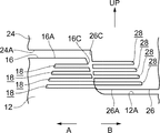
第1固定部16A及び第2固定部16Bには、それぞれ剛性低下部としての断面矩形状の固定スリット18が所定数(本実施形態では4個)形成されており、固定スリット18は、第1固定部16A及び第2固定部16Bを固定孔14の径方向において貫通している。固定スリット18は、固定孔14の周方向に延伸されており、第1固定部16A及び第2固定部16Bの固定スリット18は、それぞれ前倒方向側及び格納方向側に開放されている。所定数の固定スリット18は、上下方向に並べられており、所定数の固定スリット18は、上側から下側へ向かうに従い延伸寸法(固定孔14周方向の寸法)が徐々に大きくされている。固定スリット18は、第1固定部16A及び第2固定部16Bの剛性を低下させており、第1固定部16A及び第2固定部16Bの剛性は、上側から下側へ向かうに従い固定スリット18によって徐々に小さくされている。固定スリット18の底面(固定孔14径方向内側の面)と上面、下面及び延伸端面(固定突起16の固定孔14周方向内側の面)との間の各角部は、凹状に湾曲されており、更に、固定スリット18の延伸端面と上面及び下面との間の各角部は、凹状に湾曲されている。すなわち、固定スリット18の前記各角部は、丸みを帯びている。また、第2固定部16Bの所定数の固定スリット18は、第1固定部16Aの所定数の固定スリット18に比し、上側に配置されている。
ステー12の支持突起12Aには、格納機構としての格納装置20(図3及び図4参照)が支持されている。
格納装置20には、支持体を構成する支持部としての略円筒状のスタンド22が設けられており、スタンド22の下端部には、略円筒状の固定筒22Aが同軸上に設けられている。固定筒22Aは、支持突起12Aの固定孔14内に同軸上に挿入されて、支持突起12Aに固定されており、これにより、格納装置20がステー12に支持されている。固定筒22Aの上面の中央部には、円筒状の支持軸22B(図5参照)が一体形成されており、支持軸22Bは、上方に突出されると共に、固定筒22Aと同軸上に配置されている。
固定筒22Aの上面には、支持軸22Bの径方向外側において、制限部としての長尺湾曲柱状の制限凸部(図示省略)が複数(例えば2個)一体形成されており、制限凸部は、上方に突出されると共に、固定筒22Aの周方向に延伸されている。複数の制限凸部は、固定筒22Aの周方向に等間隔に配置されており、制限凸部の前倒方向側及び格納方向側の端面は、固定筒22Aの径方向に平行に配置されると共に、上側へ向かうに従い制限凸部の固定筒22A周方向内側へ向かう方向に傾斜されている。
スタンド22には、回動体を構成する駆動体24が支持されており、駆動体24は、支持軸22Bが挿入されると共に、スタンド22に対し下側へ付勢されている。格納装置20が駆動された際には、駆動体24がスタンド22に対し支持軸22Bを中心軸として格納方向及び前倒方向に回動される。
駆動体24の外周には、回動部材としての樹脂製のケース24Aが設けられている。
ケース24Aの下面には、支持軸22Bの周囲において、規制機構を構成する柱状の回動凸部(図示省略)が複数(例えば2個)一体形成されており、回動凸部は、下方に突出されている。複数の回動凸部は、支持軸22Bの周方向に等間隔に配置されており、回動凸部は、スタンド22(固定筒22A)の制限凸部間に配置されて、制限凸部の格納方向側の端面に当接されている。
ケース24Aの下面には、固定筒22Aの車両前側の周囲において、当接部としての長尺湾曲板状の回動突起26(回動体側ストッパ)が一体形成されており、回動突起26は、下方に突出されると共に、固定筒22Aの周方向(駆動体24の回動周方向)に延伸されている。回動突起26の格納方向側及び前倒方向側の部分は、それぞれ第1回動部26A及び第2回動部26B(図5、図6A及び図6B参照)にされている。
第1回動部26Aの格納方向側の端面(回動突起26の格納方向側の端面)及び第2回動部26Bの前倒方向側の端面(回動突起26の前倒方向側の端面)は、それぞれ当接面としての第1回動面26C及び第2回動面26Dにされており、第1回動面26C及び第2回動面26Dは、固定筒22Aの径方向(駆動体24の回動径方向)に平行に配置されている。第1回動面26C及び第2回動面26Dは、下側へ向かうに従い回動突起26の固定筒22A周方向内側へ向かう方向へ傾斜されており、第1回動面26C及び第2回動面26Dの下方に対する傾斜角度は、ステー12の固定突起16における第1固定面16C及び第2固定面16Dの上方に対する傾斜角度に比し小さくされている。第1回動面26C及び第2回動面26Dの上端部は、凹状に湾曲されており、第1回動面26C及び第2回動面26Dの下端部は、凸状に湾曲されている。
第1回動部26A及び第2回動部26Bには、それぞれ剛性低下部としての断面矩形状の回動スリット28が所定数(本実施形態では4個)形成されており、回動スリット28は、第1回動部26A及び第2回動部26Bを固定筒22Aの径方向において貫通している。回動スリット28は、固定筒22Aの周方向に延伸されており、第1回動部26A及び第2回動部26Bの回動スリット28は、それぞれ格納方向側及び前倒方向側に開放されている。所定数の回動スリット28は、上下方向に並べられており、所定数の回動スリット28は、上側から下側へ向かうに従い延伸寸法(固定筒22A周方向の寸法)が徐々に大きくされている。回動スリット28は、第1回動部26A及び第2回動部26Bの剛性を低下させており、第1回動部26A及び第2回動部26Bの剛性は、上側から下側へ向かうに従い回動スリット28によって徐々に小さくされている。回動スリット28の底面(固定筒22A径方向内側の面)と上面、下面及び延伸端面(回動突起26の固定筒22A周方向内側の面)との間の各角部は、凹状に湾曲されており、更に、回動スリット28の延伸端面と上面及び下面との間の各角部は、凹状に湾曲されている。すなわち、回動スリット28の前記各角部は、丸みを帯びている。
格納装置20の駆動体24には、回動体を構成する本体部30(図3及び図5参照)が支持されている。
本体部30には、被覆体としての樹脂製のバイザ32が設けられており、バイザ32には、本体部材としてのバイザボデー32Aが設けられている。バイザボデー32Aの車幅方向内側部分は、車両前側において、駆動体24に固定されており、これにより、バイザ32が駆動体24に支持されることで、本体部30が、駆動体24に支持されて、駆動体24と一体に回動可能にされている。本体部30は、起立位置(図5に実線で示す展開位置)に配置されており、本体部30は、ステー12に対し車幅方向外側に突出されて、起立(展開)されている。バイザボデー32Aの車両後側部分には、略直方体状の収容室34が形成されており、収容室34は、車両後側に開放されている。
バイザボデー32Aの車両前側には、被覆部材としての湾曲板状のバイザカバー32Bが設けられており、バイザカバー32Bは、バイザボデー32Aに組付けられている。バイザカバー32Bは、バイザボデー32A及び駆動体24の車両前側を被覆しており、バイザ32内には、バイザボデー32Aとバイザカバー32Bとの間において、駆動体24が収容されている。
バイザボデー32Aの収容室34には、視認機構としての略矩形板状のミラー36が収容されて支持されており、ミラー36の鏡面36A(裏側の光反射面)は、車両後側へ向けられている。このため、ミラー36が車両の乗員(特に運転者)の車両後側の視認を補助する。
次に、本実施の形態の作用を説明する。
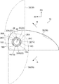
以上の構成の車両用ドアミラー装置10では、格納装置20の駆動又は本体部30(特にバイザ32)への外力の入力によって、本体部30が駆動体24と一体に起立位置(図5に実線で示す展開位置)から格納方向(車両後側かつ車幅方向内側)に回動されることで、本体部30(ミラー36を含む)が、格納位置(後格納位置、図5に2点鎖線で示す位置)に配置されて、格納(後格納)される。また、本体部30が格納位置に回動された際には、駆動体24(ケース24A)の回動凸部がスタンド22(固定筒22A)における制限凸部の前倒方向側の端面に当接されて、本体部30の格納方向への回動が制限される。
一方、格納装置20の駆動又は本体部30(特にバイザ32)への外力の入力によって、本体部30が駆動体24と一体に格納位置から前倒方向(車両前側かつ車幅方向外側)に回動されることで、本体部30(ミラー36を含む)が、起立位置に復帰されて、起立される。また、本体部30が起立位置に回動された際には、駆動体24の回動凸部がスタンド22における制限凸部の格納方向側の端面に当接されて、本体部30の前倒方向への回動が制限される。
さらに、本体部30(特にバイザ32)への外力(手動や衝突等による大きな回動力)の入力によって、本体部30が駆動体24と一体に起立位置から前倒方向(車両前側かつ車幅方向内側)に回動されることで、本体部30(ミラー36を含む)が、前倒位置(前格納位置、図5に1点鎖線で示す位置)に配置されて、前倒(前格納)される。
また、本体部30が起立位置よりも前倒方向側に配置される際には、駆動体24へのスタンド22に対する下側の付勢力に抗して、駆動体24の回動凸部がスタンド22の制限凸部に乗上げる。このため、本体部30が起立位置よりも前倒方向側に配置される際(図6B参照)には、本体部30が起立位置から格納位置までの範囲に配置される際(図6A参照)に比し、駆動体24及び本体部30がスタンド22に対して上側に移動される。
ところで、本体部30が格納位置に回動された際には、ステー12(支持突起12A)における固定突起16(第1固定部16A)の第1固定面16Cの下側部分と駆動体24(ケース24A)における回動突起26(第1回動部26A)の第1回動面26Cの下端部とが当接される(図5の2点鎖線及び図6A参照)。このため、本体部30に手動や衝突等により格納方向(車幅方向内側)への大きな回動力が入力された場合でも、本体部30の格納位置から格納方向への回動が禁止される(許容されない)。
さらに、本体部30が前倒位置に回動された際には、固定突起16(第2固定部16B)の第2固定面16Dの下側部分と回動突起26(第2回動部26B)の第2回動面26Dの下端部とが当接される(図5の1点鎖線及び図6B参照)。このため、本体部30に手動や衝突等により前倒方向(車幅方向内側)への大きな回動力が入力された場合でも、本体部30の前倒位置から前倒方向への回動が禁止される(許容されない)。
ここで、固定突起16の第1固定部16A及び第2固定部16Bの固定スリット18がそれぞれ第1固定部16A及び第2固定部16Bの剛性を低下させると共に、回動突起26の第1回動部26A及び第2回動部26Bの回動スリット28がそれぞれ第1回動部26A及び第2回動部26Bの剛性を低下させている。
このため、本体部30が格納位置に回動されて、第1固定部16Aの第1固定面16Cと第1回動部26Aの第1回動面26Cとが当接された際には、第1固定部16A及び第1回動部26Aが第1固定面16Cと第1回動面26Cとの当接力(特に衝撃力)を逃がすことができ、第1固定部16A及び第1回動部26Aの破損(特に折損)を抑制できると共に、第1固定面16Cと第1回動面26Cとの当接音を低減できる。しかも、本体部30が前倒位置に回動されて、第2固定部16Bの第2固定面16Dと第2回動部26Bの第2回動面26Dとが当接された際には、第2固定部16B及び第2回動部26Bが第2固定面16Dと第2回動面26Dとの当接力(特に衝撃力)を逃がすことができ、第2固定部16B及び第2回動部26Bの破損(特に折損)を抑制できると共に、第2固定面16Dと第2回動面26Dとの当接音を低減できる。
さらに、第1固定部16A及び第2固定部16Bにおける所定数の固定スリット18がそれぞれ上側から下側へ向かうに従い延伸寸法を徐々に大きくされており、第1固定部16A及び第2固定部16Bの下側部分の剛性がそれぞれ第1固定部16A及び第2固定部16Bの上側部分の剛性に比し低下されている。しかも、第1回動部26A及び第2回動部26Bにおける所定数の回動スリット28がそれぞれ上側から下側へ向かうに従い延伸寸法を徐々に大きくされており、第1回動部26A及び第2回動部26Bの下側部分の剛性がそれぞれ第1回動部26A及び第2回動部26Bの上側部分の剛性に比し低下されている。
このため、本体部30が格納位置に回動されて、第1固定部16Aの第1固定面16Cの下側部分と第1回動部26Aの第1回動面26Cの下端部とが当接された際には、第1固定部16Aの下側部分(当接部分側)及び第1回動部26Aの下側部分(当接部分側)が第1固定面16Cと第1回動面26Cとの当接力(特に衝撃力)を逃がすことができ、第1固定部16A及び第1回動部26Aの破損(特に折損)を適切に抑制できると共に、第1固定面16Cと第1回動面26Cとの当接音を適切に低減できる。しかも、本体部30が前倒位置に回動されて、第2固定部16Bの第2固定面16Dの下側部分と第2回動部26Bの第2回動面26Dの下端部とが当接された際には、第2固定部16Bの下側部分(当接部分側)及び第2回動部26Bの下側部分(当接部分側)が第2固定面16Dと第2回動面26Dとの当接力(特に衝撃力)を逃がすことができ、第2固定部16B及び第2回動部26Bの破損(特に折損)を適切に抑制できると共に、第2固定面16Dと第2回動面26Dとの当接音を適切に低減できる。
また、固定スリット18の底面と上面、下面及び延伸端面との間の各角部及び固定スリット18の延伸端面と上面及び下面との間の各角部が凹状に湾曲されており、回動スリット28の底面と上面、下面及び延伸端面との間の各角部及び回動スリット28の延伸端面と上面及び下面との間の各角部が凹状に湾曲されている。
このため、本体部30が格納位置に回動されて、第1固定部16Aの第1固定面16Cと第1回動部26Aの第1回動面26Cとが当接された際には、固定スリット18の上記各角部を起点とした第1固定部16Aの破損及び回動スリット28の上記各角部を起点とした第1回動部26Aの破損を抑制でき、第1固定部16A及び第1回動部26Aの破損(特に折損)を適切に抑制できる。しかも、本体部30が前倒位置に回動されて、第2固定部16Bの第2固定面16Dと第2回動部26Bの第2回動面26Dとが当接された際には、固定スリット18の上記各角部を起点とした第2固定部16Bの破損及び回動スリット28の上記各角部を起点とした第2回動部26Bの破損を抑制でき、第2固定部16B及び第2回動部26Bの破損(特に折損)を適切に抑制できる。
さらに、第1固定部16Aの第1固定面16C及び第2固定面16Dが上側へ向かうに従い固定突起16の駆動体24回動周方向内側へ向かう方向に傾斜されている。
このため、本体部30が格納位置に回動されて、第1固定部16Aの第1固定面16Cと第1回動部26Aの第1回動面26Cとが当接された際には、駆動体24へのスタンド22に対する下側の付勢力に抗して、第1回動面26Cが第1固定面16Cによる案内により上側(駆動体24回動軸方向側)に移動できて、駆動体24及び本体部30が上側に移動でき、駆動体24及び本体部30の上側への移動により第1固定面16Cと第1回動面26Cとの当接力を低減(吸収)できて、第1固定部16A及び第1回動部26Aの破損(特に折損)を効果的に抑制できると共に、第1固定面16Cと第1回動面26Cとの当接音を効果的に低減できる。しかも、本体部30が前倒位置に回動されて、第2固定部16Bの第2固定面16Dと第2回動部26Bの第2回動面26Dとが当接された際には、第2回動面26Dが第2固定面16Dによる案内により上側に移動できて、駆動体24及び本体部30が上側に移動でき、駆動体24及び本体部30の上側への移動により第2固定面16Dと第2回動面26Dとの当接力を低減(吸収)できて、第2固定部16B及び第2回動部26Bの破損(特に折損)を効果的に抑制できると共に、第2固定面16Dと第2回動面26Dとの当接音を効果的に低減できる。
また、第1固定部16A及び第2固定部16Bにおける所定数の固定スリット18がそれぞれ下側から上側へ向かうに従い延伸寸法を徐々に小さくされており、第1固定部16A及び第2固定部16Bの上側部分の剛性がそれぞれ第1固定部16A及び第2固定部16Bの下側部分の剛性に比し高くされている。しかも、第1回動部26A及び第2回動部26Bにおける所定数の回動スリット28がそれぞれ下側から上側へ向かうに従い延伸寸法を徐々に小さくされており、第1回動部26A及び第2回動部26Bの上側部分の剛性がそれぞれ第1回動部26A及び第2回動部26Bの下側部分の剛性に比し高くされている。
このため、本体部30が格納位置に回動されて、第1固定部16Aの第1固定面16Cの下側部分と第1回動部26Aの第1回動面26Cの下端部とが当接された際には、第1固定部16Aの上側部分(非当接部分側)及び第1回動部26Aの上側部分(非当接部分側)が第1固定面16Cと第1回動面26Cとの当接力(特に衝撃力)を適切に受止めることができ、本体部30の格納位置から格納方向への回動を適切に禁止できる。しかも、本体部30が前倒位置に回動されて、第2固定部16Bの第2固定面16Dの下側部分と第2回動部26Bの第2回動面26Dの下端部とが当接された際には、第2固定部16Bの上側部分(非当接部分側)及び第2回動部26Bの上側部分(非当接部分側)が第2固定面16Dと第2回動面26Dとの当接力(特に衝撃力)を適切に受止めることができ、本体部30の前倒位置から前倒方向への回動を適切に禁止できる。
なお、本実施形態では、第1固定部16A及び第2固定部16Bの上側部分に固定スリット18が設けられると共に、第1回動部26A及び第2回動部26Bの上側部分に回動スリット28が設けられる。しかしながら、第1固定部16Aの上側部分に固定スリット18が設けられない構成及び第1回動部26Aの上側部分に回動スリット28が設けられない構成の少なくとも一方にしてもよく、第2固定部16Bの上側部分に固定スリット18が設けられない構成及び第2回動部26Bの上側部分に回動スリット28が設けられない構成の少なくとも一方にしてもよい。
この場合、本体部30が格納位置に回動されて、第1固定部16Aの第1固定面16Cの下側部分と第1回動部26Aの第1回動面26Cの下端部とが当接された際には、第1固定部16Aの上側部分と第1回動部26Aの上側部分との少なくとも一方が第1固定面16Cと第1回動面26Cとの当接力(特に衝撃力)を一層適切に受止めることができ、本体部30の格納位置から格納方向への回動を一層適切に禁止できる。また、本体部30が前倒位置に回動されて、第2固定部16Bの第2固定面16Dの下側部分と第2回動部26Bの第2回動面26Dの下端部とが当接された際には、第2固定部16Bの上側部分と第2回動部26Bの上側部分との少なくとも一方が第2固定面16Dと第2回動面26Dとの当接力(特に衝撃力)を一層適切に受止めることができ、本体部30の前倒位置から前倒方向への回動を一層適切に禁止できる。
さらに、本実施形態では、第1固定部16A及び第2固定部16Bの固定スリット18が駆動体24の回動周方向に延伸されると共に、第1回動部26A及び第2回動部26Bの回動スリット28が駆動体24の回動周方向に延伸される。しかしながら、第1固定部16A及び第2固定部16Bの少なくとも一方の固定スリット18が駆動体24の回動周方向以外の方向(例えば上下方向)に延伸されてもよく、第1回動部26A及び第2回動部26Bの少なくとも一方の回動スリット28が駆動体24の回動周方向以外の方向(例えば上下方向)に延伸されてもよい。
また、本実施形態では、第1固定部16A及び第2固定部16Bに固定スリット18が設けられると共に、第1回動部26A及び第2回動部26Bに回動スリット28が設けられる。しかしながら、第1固定部16Aに固定スリット18が設けられない構成又は第1回動部26Aに回動スリット28が設けられない構成にしてもよく、第2固定部16Bに固定スリット18が設けられない構成又は第2回動部26Bに回動スリット28が設けられない構成にしてもよい。
さらに、本実施形態では、第1固定部16A及び第2固定部16Bに剛性低下部として固定スリット18が設けられると共に、第1回動部26A及び第2回動部26Bに剛性低下部として回動スリット28が設けられる。しかしながら、第1固定部16A及び第2固定部16Bの少なくとも一方に剛性低下部として周囲部分より剛性が低い低剛性材料部が設けられてもよく、第1回動部26A及び第2回動部26Bの少なくとも一方に剛性低下部として周囲部分より剛性が低い低剛性材料部が設けられてもよい。
また、本実施形態では、視認機構がミラー36にされる。しかしながら、視認機構は、撮像により乗員の視認を補助するカメラでもよい。
2018年12月27日に出願された日本国特許出願2018-245892号の開示は、その全体が参照により本明細書に取り込まれる。
Claims (7)
- 車体側に設けられる支持体と、
前記支持体に支持されると共に、乗員の視認を補助する視認機構が設けられ、回動されて格納される回動体と、
前記支持体に設けられる禁止部と、
前記回動体に設けられ、前記禁止部と当接されて前記回動体の回動が禁止される当接部と、
前記禁止部及び前記当接部の少なくとも一方に設けられ、前記禁止部及び前記当接部の少なくとも一方の剛性を低下させる剛性低下部と、
を備える車両用視認装置。 - 前記剛性低下部が前記禁止部及び前記当接部の少なくとも一方の当接部分側の剛性を前記禁止部及び前記当接部の少なくとも一方の非当接部分側の剛性に比し低下させる請求項1記載の車両用視認装置。
- 前記剛性低下部が前記禁止部及び前記当接部の少なくとも一方の非当接部分側に設けられない請求項1又は請求項2記載の車両用視認装置。
- 前記禁止部と前記当接部とが当接された際に前記当接部が前記回動体回動軸方向側に移動される請求項1~請求項3の何れか1項記載の車両用視認装置。
- 前記禁止部が長尺湾曲板状の固定突起である請求項1記載の車両用視認装置。
- 前記当接部が長尺湾曲板状の回動突起である請求項1記載の車両用視認装置。
- 前記剛性低下部が断面矩形状のスリットである請求項1記載の車両用視認装置。
Applications Claiming Priority (2)
| Application Number | Priority Date | Filing Date | Title |
|---|---|---|---|
| JP2018245892A JP2020104739A (ja) | 2018-12-27 | 2018-12-27 | 車両用視認装置 |
| JP2018-245892 | 2018-12-27 |
Publications (1)
| Publication Number | Publication Date |
|---|---|
| WO2020137393A1 true WO2020137393A1 (ja) | 2020-07-02 |
Family
ID=71126234
Family Applications (1)
| Application Number | Title | Priority Date | Filing Date |
|---|---|---|---|
| PCT/JP2019/047365 Ceased WO2020137393A1 (ja) | 2018-12-27 | 2019-12-04 | 車両用視認装置 |
Country Status (2)
| Country | Link |
|---|---|
| JP (1) | JP2020104739A (ja) |
| WO (1) | WO2020137393A1 (ja) |
Citations (1)
| Publication number | Priority date | Publication date | Assignee | Title |
|---|---|---|---|---|
| JP2012091742A (ja) * | 2010-10-28 | 2012-05-17 | Tokai Rika Co Ltd | 車両用ミラー装置 |
-
2018
- 2018-12-27 JP JP2018245892A patent/JP2020104739A/ja active Pending
-
2019
- 2019-12-04 WO PCT/JP2019/047365 patent/WO2020137393A1/ja not_active Ceased
Patent Citations (1)
| Publication number | Priority date | Publication date | Assignee | Title |
|---|---|---|---|---|
| JP2012091742A (ja) * | 2010-10-28 | 2012-05-17 | Tokai Rika Co Ltd | 車両用ミラー装置 |
Also Published As
| Publication number | Publication date |
|---|---|
| JP2020104739A (ja) | 2020-07-09 |
Similar Documents
| Publication | Publication Date | Title |
|---|---|---|
| US9630559B2 (en) | Vehicle visual recognition device | |
| US10513223B2 (en) | Viewing device for a vehicle | |
| US9981606B2 (en) | Vehicle visual recognition device | |
| JP7067740B2 (ja) | 車両用視認装置 | |
| JP5872208B2 (ja) | 車両用ミラー装置 | |
| JP2011042335A (ja) | 車両用サンバイザ構造 | |
| JP5566852B2 (ja) | 車両用ミラー装置 | |
| JP2020104739A (ja) | 車両用視認装置 | |
| JP6129488B2 (ja) | 車両用ミラー装置 | |
| JP6113638B2 (ja) | 車両用ミラー装置 | |
| JP6195510B2 (ja) | 車両用ミラー装置 | |
| JP5961461B2 (ja) | 車両用ミラー装置 | |
| EP1795394B1 (en) | Retractable door mirror | |
| JP2017190062A (ja) | ドアミラー | |
| JP6195511B2 (ja) | 車両用ミラー装置 | |
| JP6113628B2 (ja) | 車両用ミラー装置 | |
| JP6291229B2 (ja) | 車両用ミラー装置 | |
| US10442357B2 (en) | Viewing device for a vehicle | |
| JP2020040527A (ja) | アンダランプロテクタの支持構造 | |
| JP5082744B2 (ja) | 車両用アウトサイドミラー装置 | |
| JP7351770B2 (ja) | 設置装置 | |
| KR102723064B1 (ko) | 시트 벨트 리트랙터 | |
| WO2017135017A1 (ja) | 車両用視認装置 | |
| JP6656585B2 (ja) | 車両のサンバイザー | |
| JP2024111759A (ja) | 車両用視認装置 |
Legal Events
| Date | Code | Title | Description |
|---|---|---|---|
| 121 | Ep: the epo has been informed by wipo that ep was designated in this application |
Ref document number: 19905453 Country of ref document: EP Kind code of ref document: A1 |
|
| NENP | Non-entry into the national phase |
Ref country code: DE |
|
| 122 | Ep: pct application non-entry in european phase |
Ref document number: 19905453 Country of ref document: EP Kind code of ref document: A1 |