WO2020129798A1 - セラミックヒータ - Google Patents
セラミックヒータ Download PDFInfo
- Publication number
- WO2020129798A1 WO2020129798A1 PCT/JP2019/048644 JP2019048644W WO2020129798A1 WO 2020129798 A1 WO2020129798 A1 WO 2020129798A1 JP 2019048644 W JP2019048644 W JP 2019048644W WO 2020129798 A1 WO2020129798 A1 WO 2020129798A1
- Authority
- WO
- WIPO (PCT)
- Prior art keywords
- thermocouple
- outer peripheral
- ceramic plate
- passage
- peripheral side
- Prior art date
- Legal status (The legal status is an assumption and is not a legal conclusion. Google has not performed a legal analysis and makes no representation as to the accuracy of the status listed.)
- Ceased
Links
Images





Classifications
-
- H—ELECTRICITY
- H10—SEMICONDUCTOR DEVICES; ELECTRIC SOLID-STATE DEVICES NOT OTHERWISE PROVIDED FOR
- H10P—GENERIC PROCESSES OR APPARATUS FOR THE MANUFACTURE OR TREATMENT OF DEVICES COVERED BY CLASS H10
- H10P72/00—Handling or holding of wafers, substrates or devices during manufacture or treatment thereof
- H10P72/04—Apparatus for manufacture or treatment
- H10P72/0431—Apparatus for thermal treatment
- H10P72/0432—Apparatus for thermal treatment mainly by conduction
-
- H—ELECTRICITY
- H05—ELECTRIC TECHNIQUES NOT OTHERWISE PROVIDED FOR
- H05B—ELECTRIC HEATING; ELECTRIC LIGHT SOURCES NOT OTHERWISE PROVIDED FOR; CIRCUIT ARRANGEMENTS FOR ELECTRIC LIGHT SOURCES, IN GENERAL
- H05B3/00—Ohmic-resistance heating
- H05B3/10—Heating elements characterised by the composition or nature of the materials or by the arrangement of the conductor
- H05B3/12—Heating elements characterised by the composition or nature of the materials or by the arrangement of the conductor characterised by the composition or nature of the conductive material
- H05B3/14—Heating elements characterised by the composition or nature of the materials or by the arrangement of the conductor characterised by the composition or nature of the conductive material the material being non-metallic
- H05B3/141—Conductive ceramics, e.g. metal oxides, metal carbides, barium titanate, ferrites, zirconia, vitrous compounds
- H05B3/143—Conductive ceramics, e.g. metal oxides, metal carbides, barium titanate, ferrites, zirconia, vitrous compounds applied to semiconductors, e.g. wafers heating
-
- H—ELECTRICITY
- H05—ELECTRIC TECHNIQUES NOT OTHERWISE PROVIDED FOR
- H05B—ELECTRIC HEATING; ELECTRIC LIGHT SOURCES NOT OTHERWISE PROVIDED FOR; CIRCUIT ARRANGEMENTS FOR ELECTRIC LIGHT SOURCES, IN GENERAL
- H05B3/00—Ohmic-resistance heating
- H05B3/20—Heating elements having extended surface area substantially in a two-dimensional [2D] plane, e.g. plate-heater
- H05B3/22—Heating elements having extended surface area substantially in a two-dimensional [2D] plane, e.g. plate-heater non-flexible
- H05B3/28—Heating elements having extended surface area substantially in a two-dimensional [2D] plane, e.g. plate-heater non-flexible heating conductor embedded in insulating material
- H05B3/283—Heating elements having extended surface area substantially in a two-dimensional [2D] plane, e.g. plate-heater non-flexible heating conductor embedded in insulating material the insulating material being an inorganic material, e.g. ceramic
-
- G—PHYSICS
- G01—MEASURING; TESTING
- G01K—MEASURING TEMPERATURE; MEASURING QUANTITY OF HEAT; THERMALLY-SENSITIVE ELEMENTS NOT OTHERWISE PROVIDED FOR
- G01K7/00—Measuring temperature based on the use of electric or magnetic elements directly sensitive to heat ; Power supply therefor, e.g. using thermoelectric elements
- G01K7/02—Measuring temperature based on the use of electric or magnetic elements directly sensitive to heat ; Power supply therefor, e.g. using thermoelectric elements using thermoelectric elements, e.g. thermocouples
-
- H—ELECTRICITY
- H05—ELECTRIC TECHNIQUES NOT OTHERWISE PROVIDED FOR
- H05B—ELECTRIC HEATING; ELECTRIC LIGHT SOURCES NOT OTHERWISE PROVIDED FOR; CIRCUIT ARRANGEMENTS FOR ELECTRIC LIGHT SOURCES, IN GENERAL
- H05B3/00—Ohmic-resistance heating
- H05B3/20—Heating elements having extended surface area substantially in a two-dimensional [2D] plane, e.g. plate-heater
- H05B3/22—Heating elements having extended surface area substantially in a two-dimensional [2D] plane, e.g. plate-heater non-flexible
- H05B3/26—Heating elements having extended surface area substantially in a two-dimensional [2D] plane, e.g. plate-heater non-flexible heating conductor mounted on insulating base
- H05B3/265—Heating elements having extended surface area substantially in a two-dimensional [2D] plane, e.g. plate-heater non-flexible heating conductor mounted on insulating base the insulating base being an inorganic material, e.g. ceramic
-
- H—ELECTRICITY
- H05—ELECTRIC TECHNIQUES NOT OTHERWISE PROVIDED FOR
- H05B—ELECTRIC HEATING; ELECTRIC LIGHT SOURCES NOT OTHERWISE PROVIDED FOR; CIRCUIT ARRANGEMENTS FOR ELECTRIC LIGHT SOURCES, IN GENERAL
- H05B3/00—Ohmic-resistance heating
- H05B3/68—Heating arrangements specially adapted for cooking plates or analogous hot-plates
- H05B3/74—Non-metallic plates, e.g. vitroceramic, ceramic or glassceramic hobs, also including power or control circuits
-
- H—ELECTRICITY
- H10—SEMICONDUCTOR DEVICES; ELECTRIC SOLID-STATE DEVICES NOT OTHERWISE PROVIDED FOR
- H10P—GENERIC PROCESSES OR APPARATUS FOR THE MANUFACTURE OR TREATMENT OF DEVICES COVERED BY CLASS H10
- H10P72/00—Handling or holding of wafers, substrates or devices during manufacture or treatment thereof
- H10P72/06—Apparatus for monitoring, sorting, marking, testing or measuring
- H10P72/0602—Temperature monitoring
-
- H—ELECTRICITY
- H10—SEMICONDUCTOR DEVICES; ELECTRIC SOLID-STATE DEVICES NOT OTHERWISE PROVIDED FOR
- H10P—GENERIC PROCESSES OR APPARATUS FOR THE MANUFACTURE OR TREATMENT OF DEVICES COVERED BY CLASS H10
- H10P72/00—Handling or holding of wafers, substrates or devices during manufacture or treatment thereof
- H10P72/70—Handling or holding of wafers, substrates or devices during manufacture or treatment thereof for supporting or gripping
- H10P72/76—Handling or holding of wafers, substrates or devices during manufacture or treatment thereof for supporting or gripping using mechanical means, e.g. clamps or pinches
- H10P72/7604—Handling or holding of wafers, substrates or devices during manufacture or treatment thereof for supporting or gripping using mechanical means, e.g. clamps or pinches the wafers being placed on a susceptor, stage or support
- H10P72/7616—Handling or holding of wafers, substrates or devices during manufacture or treatment thereof for supporting or gripping using mechanical means, e.g. clamps or pinches the wafers being placed on a susceptor, stage or support characterised by a coating, a hardness or a material
-
- H—ELECTRICITY
- H10—SEMICONDUCTOR DEVICES; ELECTRIC SOLID-STATE DEVICES NOT OTHERWISE PROVIDED FOR
- H10P—GENERIC PROCESSES OR APPARATUS FOR THE MANUFACTURE OR TREATMENT OF DEVICES COVERED BY CLASS H10
- H10P95/00—Generic processes or apparatus for manufacture or treatments not covered by the other groups of this subclass
Definitions
- the present invention has been made to solve such a problem, and its main purpose is to accurately measure the temperature of the outer peripheral zone.
- the ceramic heater of the present invention is A disk-shaped ceramic plate having a wafer mounting surface,
- the ceramic plate is built in and extends from one of a pair of terminals provided in the central portion of the ceramic plate to an annular outer peripheral side zone of the ceramic plate, and is folded back at a plurality of folding portions in the outer peripheral side zone.
- An outer peripheral resistance heating element having a shape reaching the other of the pair of terminals after wiring,
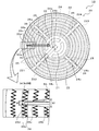
- An outer peripheral thermocouple that measures the temperature of the outer peripheral zone with a temperature measuring unit at the tip, Equipped with When the ceramic plate is viewed from the wafer mounting surface, the temperature measuring unit is arranged at a position in the outer peripheral zone excluding a portion where the folded-back portions of the outer peripheral resistance heating element face each other. , It is a thing.
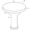
- the ceramic plate 20 is a disk-shaped plate made of ceramics such as aluminum nitride and alumina.
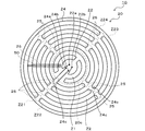
- the ceramic plate 20 is divided into a small circular inner peripheral side zone Z1 and an annular outer peripheral side zone Z2 by a virtual boundary 20c concentric with the ceramic plate 20 (see FIG. 3).
- An inner peripheral side resistance heating element 22 is embedded in the inner peripheral side zone Z1 of the ceramic plate 20, and an outer peripheral side resistance heating element 24 is embedded in the outer peripheral side zone Z2.
- Both resistance heating elements 22 and 24 are composed of a coil whose main component is molybdenum, tungsten or tungsten carbide, for example.
- the ceramic plate 20 is made by surface-bonding an upper plate P1 and a lower plate P2 thinner than the upper plate P1, which will be described later.
- the outer peripheral resistance heating element 24 originates from one of a pair of terminals 24a and 24b arranged in the central portion of the ceramic plate 20, and is formed by a plurality of folded portions 24c in a single stroke. It is formed so as to be folded back and wired in almost the entire area of the outer peripheral side zone Z2 and then reach the other of the pair of terminals 24a, 24b.
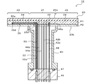
- thermocouple passage 26 is provided along the radial direction of the ceramic plate 20 in parallel with the wafer mounting surface 20a.
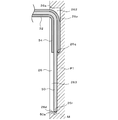
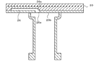
- the thermocouple passage 26 is a passage from an insertion opening 26a for inserting the outer thermocouple 50 into the back surface 20b on the center side of the ceramic plate 20 to a terminal position 26d before the outer peripheral surface of the ceramic plate 20.
- the terminal position 26d is a position where the temperature measuring unit 50a provided at the tip of the outer peripheral thermocouple 50 is arranged. As shown in FIGS.
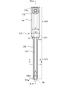
- thermocouple guide 32 On the back surface of the ceramic plate 20, as shown in FIG. 2, a pipe-shaped thermocouple guide 32 having a guide hole 32a inside is attached to the insertion port 26a of the thermocouple passage 26.
- the thermocouple guide 32 is formed in an L-shape that curves from the vertical direction and changes its direction in the horizontal direction, and the horizontal portion is attached to the insertion port 26a.
- the thermocouple guide 32 is made of stainless steel or ceramics.
- As a method of attaching the thermocouple guide 32 to the insertion port 26a for example, diffusion bonding, brazing, screwing, or the like can be adopted, but it is also possible to simply fit without joining.
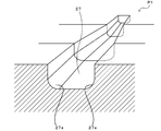
- thermocouple passage 26 is a passage having a substantially quadrangular cross section, and the boundary portion (corner portion 27a) between the ceiling surface and the side surface thereof is an R surface having a radius of curvature of 0.5 mm or more. Therefore, it is possible to suppress the occurrence of cracks in the ceramic plate 20 starting from the boundary between the ceiling surface and the side surface.
- the corner 27a is used as a starting point. It is possible to suppress the occurrence of cracks in the ceramic plate 20. Incidentally, cracks occurred when the radius of curvature of the corner portion 27a was 0.1 mm and 0.3 mm, but did not occur when they were 0.5 mm, 0.7 mm, and 0.9 mm.
- the ceramic plate 20 may have built-in electrostatic electrodes in addition to the resistance heating elements 22 and 24. In this way, the wafer can be electrostatically attracted to the wafer mounting surface 20a by applying a voltage to the electrostatic electrode after mounting the wafer on the wafer mounting surface 20a.
- the ceramic plate 20 may have an RF electrode built therein. In that case, a shower head (not shown) is arranged with a space above the wafer mounting surface 20a, and high frequency power is supplied between the parallel plate electrodes including the shower head and the RF electrodes. By doing so, plasma can be generated and the wafer can be subjected to CVD film formation or etching using the plasma.
- the electrostatic electrode may also be used as the RF electrode.
- the outer peripheral thermocouple 50 is not easily distorted when the outer peripheral thermocouple 50 is inserted, and the outer peripheral thermocouple 50 is located at a desired measurement point (a point in the ceramic plate 20 near the end position 26d). This is because it is easy to arrange the temperature measuring unit 50a of the pair 50.
- the clearance in each width direction (the value obtained by subtracting the outer diameter D of the tip portion 34 from the width W of the wide portion 262 and the width). It is preferable that the value obtained by subtracting the outer diameter d of the outer peripheral side thermocouple 50 from the width w of the narrow portion 263 is 2 mm or less. Similarly, the clearance in the depth direction is preferably 2 mm or less.
- the tip portion 34 of the thermocouple guide 32 is arranged in a portion of the bottom surface 26p from the starting point 26s to the step 26q, and the outer peripheral thermocouple 50 extends along the portion of the bottom surface 26p from the step 26q to the end position 26d. Is inserted. Therefore, the outer thermocouple 50 can be smoothly inserted into the thermocouple passage 26 by utilizing the thermocouple guide 32. Moreover, since the gap between the temperature measuring unit 50a and the bottom surface 26p becomes smaller due to the existence of the inclined surface 26r, the temperature measuring accuracy of the temperature measuring unit 50a is improved.
- the bottom surface 26p of the thermocouple passage 26 may be a flat surface.
Landscapes
- Chemical & Material Sciences (AREA)
- Engineering & Computer Science (AREA)
- Ceramic Engineering (AREA)
- Physics & Mathematics (AREA)
- General Physics & Mathematics (AREA)
- Inorganic Chemistry (AREA)
- Resistance Heating (AREA)
- Surface Heating Bodies (AREA)
Abstract
Description
ウエハ載置面を有する円盤状のセラミックプレートと、
前記セラミックプレートに内蔵され、前記セラミックプレートの中央部に設けられた一対の端子の一方から前記セラミックプレートの円環状の外周側ゾーンに延び出し、前記外周側ゾーンにおいて複数の折り返し部で折り返されつつ配線されたあと、前記一対の端子の他方に至る形状の外周側抵抗発熱体と、
先端の測温部で前記外周側ゾーンの温度を測定する外周側熱電対と、
を備え、
前記測温部は、前記セラミックプレートを前記ウエハ載置面からみたとき、前記外周側ゾーンのうち前記外周側抵抗発熱体の前記折り返し部同士が向かい合っている部分を除いた位置に配置されている、
ものである。
「ウエハ載置面を有する円盤状のセラミックプレートと、
前記セラミックプレートに内蔵され、前記セラミックプレートの中央部に設けられた一対の端子の一方から前記セラミックプレートの円環状の外周側ゾーンに延び出し、前記外周側ゾーンにおいて複数の折り返し部で折り返されつつ配線されたあと、前記一対の端子の他方に至る形状の外周側抵抗発熱体と、
先端の測温部で前記外周側ゾーンの温度を測定する外周側熱電対と、
前記セラミックプレートの内部に前記ウエハ載置面と平行に設けられ、前記セラミックプレートの中央部のうち前記ウエハ載置面とは反対側の面に開口した挿入口から前記セラミックプレートの外周面の手前の終端位置に至る熱電対通路と、
を備え、
前記終端位置は、前記外周側熱電対の測温部が配置される位置であり、
前記熱電対通路の高さは、前記挿入口から前記終端位置まで一定であり、
前記熱電対通路の幅は、前記挿入口から前記終端位置の手前の第1の中間位置までは一定の幅W1であり、前記第1の中間位置からそれより奥の第2の中間位置まではテーパ面によって徐々に幅が狭くなっており、前記第2の中間位置から前記終端位置までは一定の幅W2となっている、
セラミックヒータ。」
の一例でもある。
Claims (12)
- ウエハ載置面を有する円盤状のセラミックプレートと、
前記セラミックプレートに内蔵され、前記セラミックプレートの中央部に設けられた一対の端子の一方から前記セラミックプレートの円環状の外周側ゾーンに延び出し、前記外周側ゾーンにおいて複数の折り返し部で折り返されつつ配線されたあと、前記一対の端子の他方に至る形状の外周側抵抗発熱体と、
先端の測温部で前記外周側ゾーンの温度を測定する外周側熱電対と、
を備え、
前記測温部は、前記セラミックプレートを前記ウエハ載置面からみたとき、前記外周側ゾーンのうち前記外周側抵抗発熱体の前記折り返し部同士が向かい合っている部分を除いた位置に配置されている、
セラミックヒータ。 - 前記外周側ゾーンは、前記セラミックプレートの中心と前記外周側抵抗発熱体の複数の前記折り返し部の各々とを結んだ線分によって複数の扇領域に分割され、
前記測温部が配置される位置は、前記扇領域内に設けられている、
請求項1に記載のセラミックヒータ。 - 前記測温部が配置される位置は、前記セラミックプレートを前記ウエハ載置面からみたときに前記外周側抵抗発熱体の幅の中に設けられている、
請求項1又は2に記載のセラミックヒータ。 - 請求項1~3のいずれか1項に記載のセラミックヒータであって、
前記セラミックプレートの内部に前記ウエハ載置面と平行に設けられ、前記セラミックプレートの中央部のうち前記ウエハ載置面とは反対側の面に開口した挿入口から前記セラミックプレートの外周面の手前の終端位置に至る熱電対通路
を備えるセラミックヒータ。 - 前記終端位置は、前記外周側熱電対の測温部が配置される位置であり、
前記熱電対通路の高さは、前記挿入口から前記終端位置まで一定であり、
前記熱電対通路の幅は、前記挿入口から前記終端位置の手前の第1の中間位置までは一定の幅W1であり、前記第1の中間位置からそれより奥の第2の中間位置まではテーパ面によって徐々に幅が狭くなっており、前記第2の中間位置から前記終端位置までは一定の幅W2となっている、
請求項4に記載のセラミックヒータ。 - 幅W2は前記外周側熱電対の外径dの1.2倍以上2.2倍以下である、
請求項4又は5に記載のセラミックヒータ。 - 前記終端位置は、前記外周側抵抗発熱体の幅の中に設けられている、
請求項4~6のいずれか1項に記載のセラミックヒ-タ。 - 前記熱電対通路は、断面略四角形の通路であり、前記通路の天井面と側面との境界部は、曲率半径が0.5mm以上のR面である、
請求項4~7のいずれか1項に記載のセラミックヒータ。 - 前記熱電対通路の天井面は、前記挿入口から前記終端位置までの途中に傾斜状の段差を有し、前記天井面のうち前記挿入口から前記段差までの深さは前記段差から前記終端位置までの深さよりも深い、
請求項4~8のいずれか1項に記載のセラミックヒータ。 - 前記外周側熱電対の測温部は凸状曲面であり、前記熱電対通路の終端面のうち前記外周側熱電対の測温部が接触する部分は凹状曲面である、
請求項4~9のいずれか1項に記載のセラミックヒータ。 - 前記熱電対通路と前記一対の端子のそれぞれとの間隔は、2mm以上である、
請求項4~10のいずれか1項に記載のセラミックヒータ。 - 前記熱電対通路の前記挿入口側の壁は、前記セラミックプレートのうち前記ウエハ載置面とは反対側の裏面から前記熱電対通路の奥に向かって湾曲している、
請求項4~11のいずれか1項に記載のセラミックヒータ。
Priority Applications (4)
| Application Number | Priority Date | Filing Date | Title |
|---|---|---|---|
| KR1020217011815A KR102549820B1 (ko) | 2018-12-20 | 2019-12-12 | 세라믹 히터 |
| CN201980049967.XA CN112514534B (zh) | 2018-12-20 | 2019-12-12 | 陶瓷加热器 |
| JP2020561350A JP7181314B2 (ja) | 2018-12-20 | 2019-12-12 | セラミックヒータ |
| US17/233,919 US12089297B2 (en) | 2018-12-20 | 2021-04-19 | Ceramic heater |
Applications Claiming Priority (2)
| Application Number | Priority Date | Filing Date | Title |
|---|---|---|---|
| JP2018-238224 | 2018-12-20 | ||
| JP2018238224 | 2018-12-20 |
Related Child Applications (1)
| Application Number | Title | Priority Date | Filing Date |
|---|---|---|---|
| US17/233,919 Continuation US12089297B2 (en) | 2018-12-20 | 2021-04-19 | Ceramic heater |
Publications (1)
| Publication Number | Publication Date |
|---|---|
| WO2020129798A1 true WO2020129798A1 (ja) | 2020-06-25 |
Family
ID=71102167
Family Applications (1)
| Application Number | Title | Priority Date | Filing Date |
|---|---|---|---|
| PCT/JP2019/048644 Ceased WO2020129798A1 (ja) | 2018-12-20 | 2019-12-12 | セラミックヒータ |
Country Status (6)
| Country | Link |
|---|---|
| US (1) | US12089297B2 (ja) |
| JP (1) | JP7181314B2 (ja) |
| KR (1) | KR102549820B1 (ja) |
| CN (1) | CN112514534B (ja) |
| TW (1) | TWI730547B (ja) |
| WO (1) | WO2020129798A1 (ja) |
Cited By (2)
| Publication number | Priority date | Publication date | Assignee | Title |
|---|---|---|---|---|
| WO2025197024A1 (ja) * | 2024-03-21 | 2025-09-25 | 日本碍子株式会社 | 半導体製造装置用部材 |
| KR20260015256A (ko) | 2023-07-25 | 2026-02-02 | 스미토모덴키고교가부시키가이샤 | 웨이퍼 가열 장치 및 웨이퍼 가열 방법 |
Families Citing this family (5)
| Publication number | Priority date | Publication date | Assignee | Title |
|---|---|---|---|---|
| US11774298B2 (en) * | 2020-02-12 | 2023-10-03 | Tokyo Electron Limited | Multi-point thermocouples and assemblies for ceramic heating structures |
| JP7348877B2 (ja) * | 2020-04-20 | 2023-09-21 | 日本碍子株式会社 | セラミックヒータ及びその製法 |
| KR102949684B1 (ko) * | 2021-12-06 | 2026-04-07 | 가부시키가이샤 코쿠사이 엘렉트릭 | 천장 히터, 기판 처리 방법, 반도체 장치의 제조 방법 및 기판 처리 장치 |
| JP7864548B2 (ja) * | 2022-05-20 | 2026-05-25 | 日本特殊陶業株式会社 | セラミックスヒータ |
| JP1766094S (ja) * | 2023-12-01 | 2024-03-19 | 半導体ウェハ及びサセプタ加熱用ヒータ |
Citations (5)
| Publication number | Priority date | Publication date | Assignee | Title |
|---|---|---|---|---|
| JP2007142441A (ja) * | 2006-12-01 | 2007-06-07 | Kyocera Corp | ウェハ支持部材 |
| JP2010177595A (ja) * | 2009-01-30 | 2010-08-12 | Sumitomo Electric Ind Ltd | 半導体製造装置用ウエハ保持体、及びそれを備えた半導体製造装置 |
| WO2012039453A1 (ja) * | 2010-09-24 | 2012-03-29 | 日本碍子株式会社 | 半導体製造装置部材 |
| JP2012080103A (ja) * | 2010-10-01 | 2012-04-19 | Ngk Insulators Ltd | サセプター及びその製法 |
| JP2012160368A (ja) * | 2011-02-01 | 2012-08-23 | Nihon Ceratec Co Ltd | セラミックスヒータ及びその製造方法 |
Family Cites Families (11)
| Publication number | Priority date | Publication date | Assignee | Title |
|---|---|---|---|---|
| JPS551467U (ja) | 1978-06-20 | 1980-01-08 | ||
| JPH06298593A (ja) | 1993-04-09 | 1994-10-25 | Nippon Steel Corp | 単結晶引上げ装置 |
| KR200178800Y1 (ko) | 1999-11-15 | 2000-04-15 | 포항종합제철주식회사 | 고로 노저부 열전대 설치 구조 |
| JP4009138B2 (ja) * | 2002-05-27 | 2007-11-14 | 京セラ株式会社 | ウエハ支持部材 |
| JP3904986B2 (ja) * | 2002-06-26 | 2007-04-11 | 京セラ株式会社 | ウェハ支持部材 |
| TWI353631B (en) * | 2004-06-28 | 2011-12-01 | Kyocera Corp | Wafer heating device and semiconductor equipment |
| JP2006153706A (ja) | 2004-11-30 | 2006-06-15 | Taiyo Nippon Sanso Corp | 測温体および気相成長装置 |
| KR20090012710A (ko) * | 2007-07-31 | 2009-02-04 | 피에스케이 주식회사 | 기판 처리 장치 |
| JP2009054871A (ja) * | 2007-08-28 | 2009-03-12 | Tokyo Electron Ltd | 載置台構造及び処理装置 |
| JP4853432B2 (ja) * | 2007-09-05 | 2012-01-11 | 東京エレクトロン株式会社 | 載置台構造及び処理装置 |
| CN105282877B (zh) * | 2014-06-17 | 2019-10-25 | 住友电气工业株式会社 | 用于半导体制造装置的陶瓷加热器 |
-
2019
- 2019-12-12 WO PCT/JP2019/048644 patent/WO2020129798A1/ja not_active Ceased
- 2019-12-12 JP JP2020561350A patent/JP7181314B2/ja active Active
- 2019-12-12 KR KR1020217011815A patent/KR102549820B1/ko active Active
- 2019-12-12 CN CN201980049967.XA patent/CN112514534B/zh active Active
- 2019-12-16 TW TW108145966A patent/TWI730547B/zh active
-
2021
- 2021-04-19 US US17/233,919 patent/US12089297B2/en active Active
Patent Citations (5)
| Publication number | Priority date | Publication date | Assignee | Title |
|---|---|---|---|---|
| JP2007142441A (ja) * | 2006-12-01 | 2007-06-07 | Kyocera Corp | ウェハ支持部材 |
| JP2010177595A (ja) * | 2009-01-30 | 2010-08-12 | Sumitomo Electric Ind Ltd | 半導体製造装置用ウエハ保持体、及びそれを備えた半導体製造装置 |
| WO2012039453A1 (ja) * | 2010-09-24 | 2012-03-29 | 日本碍子株式会社 | 半導体製造装置部材 |
| JP2012080103A (ja) * | 2010-10-01 | 2012-04-19 | Ngk Insulators Ltd | サセプター及びその製法 |
| JP2012160368A (ja) * | 2011-02-01 | 2012-08-23 | Nihon Ceratec Co Ltd | セラミックスヒータ及びその製造方法 |
Cited By (2)
| Publication number | Priority date | Publication date | Assignee | Title |
|---|---|---|---|---|
| KR20260015256A (ko) | 2023-07-25 | 2026-02-02 | 스미토모덴키고교가부시키가이샤 | 웨이퍼 가열 장치 및 웨이퍼 가열 방법 |
| WO2025197024A1 (ja) * | 2024-03-21 | 2025-09-25 | 日本碍子株式会社 | 半導体製造装置用部材 |
Also Published As
| Publication number | Publication date |
|---|---|
| KR20210055090A (ko) | 2021-05-14 |
| JP7181314B2 (ja) | 2022-11-30 |
| KR102549820B1 (ko) | 2023-06-30 |
| JPWO2020129798A1 (ja) | 2021-10-21 |
| TW202102052A (zh) | 2021-01-01 |
| CN112514534A (zh) | 2021-03-16 |
| CN112514534B (zh) | 2022-10-28 |
| TWI730547B (zh) | 2021-06-11 |
| US20210243848A1 (en) | 2021-08-05 |
| US12089297B2 (en) | 2024-09-10 |
Similar Documents
| Publication | Publication Date | Title |
|---|---|---|
| JP7181314B2 (ja) | セラミックヒータ | |
| JP6743325B1 (ja) | セラミックヒータ | |
| KR102604134B1 (ko) | 세라믹 히터 | |
| CN113056961B (zh) | 陶瓷加热器 | |
| JP7348877B2 (ja) | セラミックヒータ及びその製法 | |
| WO2020153071A1 (ja) | セラミックヒータ | |
| US20210242053A1 (en) | Ceramic heater | |
| US20210242047A1 (en) | Ceramic heater and manufacturing method for same | |
| TWI811694B (zh) | 熱電偶導件以及陶瓷加熱器 | |
| US11895742B2 (en) | Ceramic heater | |
| US11874180B2 (en) | Ceramic heater | |
| TWI770737B (zh) | 陶瓷加熱器 | |
| TW202137810A (zh) | 陶瓷加熱器以及熱電偶導件 | |
| JP7727114B1 (ja) | セラミックヒータ |
Legal Events
| Date | Code | Title | Description |
|---|---|---|---|
| 121 | Ep: the epo has been informed by wipo that ep was designated in this application |
Ref document number: 19897855 Country of ref document: EP Kind code of ref document: A1 |
|
| ENP | Entry into the national phase |
Ref document number: 2020561350 Country of ref document: JP Kind code of ref document: A |
|
| ENP | Entry into the national phase |
Ref document number: 20217011815 Country of ref document: KR Kind code of ref document: A |
|
| NENP | Non-entry into the national phase |
Ref country code: DE |
|
| 122 | Ep: pct application non-entry in european phase |
Ref document number: 19897855 Country of ref document: EP Kind code of ref document: A1 |