WO2020129754A1 - セラミックヒータ - Google Patents
セラミックヒータ Download PDFInfo
- Publication number
- WO2020129754A1 WO2020129754A1 PCT/JP2019/048313 JP2019048313W WO2020129754A1 WO 2020129754 A1 WO2020129754 A1 WO 2020129754A1 JP 2019048313 W JP2019048313 W JP 2019048313W WO 2020129754 A1 WO2020129754 A1 WO 2020129754A1
- Authority
- WO
- WIPO (PCT)
- Prior art keywords
- thermocouple
- ceramic plate
- ceramic heater
- resistance heating
- ceramic
- Prior art date
- Legal status (The legal status is an assumption and is not a legal conclusion. Google has not performed a legal analysis and makes no representation as to the accuracy of the status listed.)
- Ceased
Links
Images



Classifications
-
- H—ELECTRICITY
- H05—ELECTRIC TECHNIQUES NOT OTHERWISE PROVIDED FOR
- H05B—ELECTRIC HEATING; ELECTRIC LIGHT SOURCES NOT OTHERWISE PROVIDED FOR; CIRCUIT ARRANGEMENTS FOR ELECTRIC LIGHT SOURCES, IN GENERAL
- H05B3/00—Ohmic-resistance heating
- H05B3/10—Heating elements characterised by the composition or nature of the materials or by the arrangement of the conductor
- H05B3/12—Heating elements characterised by the composition or nature of the materials or by the arrangement of the conductor characterised by the composition or nature of the conductive material
- H05B3/14—Heating elements characterised by the composition or nature of the materials or by the arrangement of the conductor characterised by the composition or nature of the conductive material the material being non-metallic
- H05B3/141—Conductive ceramics, e.g. metal oxides, metal carbides, barium titanate, ferrites, zirconia, vitrous compounds
- H05B3/143—Conductive ceramics, e.g. metal oxides, metal carbides, barium titanate, ferrites, zirconia, vitrous compounds applied to semiconductors, e.g. wafers heating
-
- H—ELECTRICITY
- H05—ELECTRIC TECHNIQUES NOT OTHERWISE PROVIDED FOR
- H05B—ELECTRIC HEATING; ELECTRIC LIGHT SOURCES NOT OTHERWISE PROVIDED FOR; CIRCUIT ARRANGEMENTS FOR ELECTRIC LIGHT SOURCES, IN GENERAL
- H05B3/00—Ohmic-resistance heating
- H05B3/10—Heating elements characterised by the composition or nature of the materials or by the arrangement of the conductor
- H05B3/12—Heating elements characterised by the composition or nature of the materials or by the arrangement of the conductor characterised by the composition or nature of the conductive material
- H05B3/14—Heating elements characterised by the composition or nature of the materials or by the arrangement of the conductor characterised by the composition or nature of the conductive material the material being non-metallic
- H05B3/141—Conductive ceramics, e.g. metal oxides, metal carbides, barium titanate, ferrites, zirconia, vitrous compounds
-
- H—ELECTRICITY
- H05—ELECTRIC TECHNIQUES NOT OTHERWISE PROVIDED FOR
- H05B—ELECTRIC HEATING; ELECTRIC LIGHT SOURCES NOT OTHERWISE PROVIDED FOR; CIRCUIT ARRANGEMENTS FOR ELECTRIC LIGHT SOURCES, IN GENERAL
- H05B3/00—Ohmic-resistance heating
- H05B3/20—Heating elements having extended surface area substantially in a two-dimensional [2D] plane, e.g. plate-heater
- H05B3/22—Heating elements having extended surface area substantially in a two-dimensional [2D] plane, e.g. plate-heater non-flexible
- H05B3/28—Heating elements having extended surface area substantially in a two-dimensional [2D] plane, e.g. plate-heater non-flexible heating conductor embedded in insulating material
- H05B3/283—Heating elements having extended surface area substantially in a two-dimensional [2D] plane, e.g. plate-heater non-flexible heating conductor embedded in insulating material the insulating material being an inorganic material, e.g. ceramic
-
- H—ELECTRICITY
- H05—ELECTRIC TECHNIQUES NOT OTHERWISE PROVIDED FOR
- H05B—ELECTRIC HEATING; ELECTRIC LIGHT SOURCES NOT OTHERWISE PROVIDED FOR; CIRCUIT ARRANGEMENTS FOR ELECTRIC LIGHT SOURCES, IN GENERAL
- H05B3/00—Ohmic-resistance heating
- H05B3/68—Heating arrangements specially adapted for cooking plates or analogous hot-plates
- H05B3/74—Non-metallic plates, e.g. vitroceramic, ceramic or glassceramic hobs, also including power or control circuits
-
- H—ELECTRICITY
- H10—SEMICONDUCTOR DEVICES; ELECTRIC SOLID-STATE DEVICES NOT OTHERWISE PROVIDED FOR
- H10P—GENERIC PROCESSES OR APPARATUS FOR THE MANUFACTURE OR TREATMENT OF DEVICES COVERED BY CLASS H10
- H10P95/00—Generic processes or apparatus for manufacture or treatments not covered by the other groups of this subclass
Definitions
- the present invention relates to a ceramic heater.
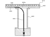
- Patent Document 1 discloses a ceramic heater 410 with a shaft shown in FIG.
- the ceramic heater 410 with a shaft measures the temperature on the outer peripheral side of the ceramic plate 420 with an outer peripheral side thermocouple 450.
- the thermocouple guide 432 is a tubular member, and extends straight from the lower side to the upper side inside the straight shaft 440 and is then bent in an arc shape to change the direction by 90°.
- the thermocouple guide 432 is attached to a slit 426a provided in a region surrounded by the straight shaft 440 on the back surface of the ceramic plate 420.
- the slit 426a forms an inlet portion of the thermocouple passage 426, and is provided in a region surrounded by the shaft 440 (a region in the shaft) on the back surface of the ceramic plate 420 along the diameter direction of the ceramic plate 420.
- the outer peripheral side thermocouple 450 is inserted into the cylinder of the thermocouple guide 432 and reaches the end position of the thermocouple passage 426.
- the inner region of the shaft is divided into two divided regions having substantially the same area by the slit 426a. Therefore, when a plurality of terminals are collectively arranged in one divided region, the arrangement is free. The degree was sometimes limited.
- the present invention has been made to solve such a problem, and its main purpose is to increase the degree of freedom in the arrangement of a plurality of terminals collectively in a multi-zone heater.
- the ceramic heater of the present invention is A disk-shaped ceramic plate having a wafer mounting surface, A cylindrical shaft joined to the back surface of the ceramic plate opposite to the wafer mounting surface, An inner peripheral side resistance heating element embedded in the inner peripheral portion of the ceramic plate, An outer peripheral resistance heating element embedded in the outer peripheral portion of the ceramic plate, A shaft inner region that is inside the tubular shaft on the back surface of the ceramic plate; An elongated hole provided along a direction deviating from the diametrical direction of the ceramic plate and extending from the inner region of the shaft to a predetermined position on the outer peripheral portion of the ceramic plate, An auxiliary component that is provided in the shaft inner region and includes a pair of terminals of the inner resistance heating element and a pair of terminals of the outer resistance heating element, Equipped with A portion of the elongated hole that passes through the shaft inner region is an elongated groove,
- the accessory component is provided collectively in a divided area having a larger area of the two divided areas divided by the axis of the long groove in the shaft inner area
- the accessory parts including the pair of terminals of the resistance heating element on the inner circumference side and the pair of terminals of the resistance heating element on the outer circumference side are provided in the shaft inner area on the back surface of the ceramic plate.
- the elongated hole is provided along a direction deviating from the diametrical direction of the ceramic plate and extends from the inner region of the shaft to a predetermined position on the outer peripheral portion of the ceramic plate.
- a portion of the long hole that passes through the shaft inner region is a long groove.
- the two divided regions of the shaft inner region are divided by the axis of the elongated groove (the same as the axis of the elongated hole and a straight line in a direction deviating from the diametrical direction of the ceramic plate).
- one of the two divided areas has a larger area than the other.
- the accessory parts are collectively provided in the divided area having the larger area. Therefore, in the multi-zone heater, it is possible to increase the degree of freedom in arranging auxiliary components including a plurality of terminals in a collective manner. By collectively providing the accessory components, it is easy to bundle the wires from the accessory components to the external device.
- the auxiliary components other than the respective terminals of the inner peripheral side and the outer peripheral side resistance heating elements are regions surrounded by the respective inner peripheral side and outer peripheral side resistance heating element terminals. May not exist.
- each of the accessory parts may be arranged at a position where electrical insulation can be maintained. Since the accessory parts are collectively provided in the larger divided area, it is possible to easily arrange the plurality of terminals and the like included in the accessory part at a position where electrical insulation can be maintained.
- the slot may be a thermocouple slot for inserting a thermocouple.
- the thermocouple can be inserted using the elongated hole.
- the long groove may be used for disposing a tubular thermocouple guide having a curved portion that changes from a vertical direction to a horizontal direction with respect to the wafer mounting surface.
- the length of the long groove may be set to be equal to or longer than the length of the tip portion of the curved portion of the thermocouple guide which is arranged in the long groove. In this way, the thermocouple guide can be easily set.
- the outer diameter of the curved portion of the thermocouple guide may be smaller than the outer diameter of the vertical portion. By doing so, the width of the long groove can be reduced.
- the ceramic heater of the present invention may include the thermocouple guide arranged in the elongated groove, and may further include the thermocouple guide and the thermocouple inserted in the elongated hole.
- the temperature measuring portion of the thermocouple may be arranged so as to fit within the width of the outer peripheral resistance heating element. With this configuration, the temperature change of the resistance heating element on the outer peripheral side can be detected with good response by the temperature measuring unit of the thermocouple on the outer peripheral side.
- the distance between the long groove and the accessory may be 2 mm or more. In this way, it is possible to prevent the ceramic plate from being cracked because the space between the long groove and the accessory is too narrow.
- FIG. 2 is a sectional view taken along line AA of FIG. 1.
- FIG. 2 is a sectional view taken along line BB of FIG. 1.
- the front view of the thermocouple guide 32 The enlarged view of the central part of FIG. Explanatory drawing of the arrangement position of terminal 22a, 22b, 24a, 24b.
- the front view of another example of the thermocouple guide 32 Explanatory drawing which shows an example of the position of the temperature measuring part 50a of the outer peripheral side thermocouple 50. Explanatory drawing which shows the space
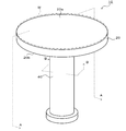
- FIG. 1 is a perspective view of the ceramic heater 10
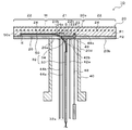
- FIG. 2 is a sectional view taken along line AA of FIG. 1
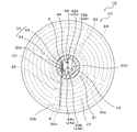
- FIG. 3 is a sectional view taken along line BB of FIG. 1
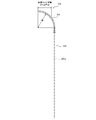
- FIG. 4 is a front view of a thermocouple guide 32, and FIG. It is an enlarged view of the central part of.
- the ceramic heater 10 is used to heat a wafer to be subjected to processing such as etching and CVD, and is installed in a vacuum chamber (not shown).
- the ceramic heater 10 includes a disk-shaped ceramic plate 20 having a wafer mounting surface 20a and a cylindrical shaft 40 joined to a surface (back surface) 20b of the ceramic plate 20 opposite to the wafer mounting surface 20a. I have it.
- the ceramic plate 20 is a disc-shaped plate made of a ceramic material typified by aluminum nitride or alumina.
- the diameter of the ceramic plate 20 is not particularly limited, but is, for example, about 300 mm.
- the ceramic plate 20 is divided into a small circular inner peripheral side zone Z1 and an annular outer peripheral side zone Z2 by a virtual boundary 20c concentric with the ceramic plate 20 (see FIG. 3).
- An inner peripheral side resistance heating element 22 is embedded in the inner peripheral side zone Z1 of the ceramic plate 20, and an outer peripheral side resistance heating element 24 is embedded in the outer peripheral side zone Z2.
- Both resistance heating elements 22 and 24 are composed of a coil whose main component is molybdenum, tungsten or tungsten carbide, for example.
- the ceramic plate 20 is manufactured by surface-bonding an upper plate P1 and a lower plate P2 thinner than the upper plate P1.
- the tubular shaft 40 is made of ceramics such as aluminum nitride and alumina.
- the upper end of the tubular shaft 40 is diffusion bonded to the ceramic plate 20.
- the resistance heating element 22 on the inner circumference side starts from one of the pair of terminals 22a and 22b, and is folded back at a plurality of folding parts in a one-stroke manner while being almost entirely covered by the zone Z1 on the inner circumference side. Is formed so as to reach the other of the pair of terminals 22a and 22b.
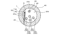
- the pair of terminals 22a and 22b are provided in a region 20d inside the cylindrical shaft 40 (region inside the shaft) of the back surface 20b of the ceramic plate 20.
- Metal (for example, Ni) power supply rods 42a and 42b are joined to the pair of terminals 22a and 22b, respectively.
- the power supply rods 42a and 42b are inserted into an insulating pipe (not shown).
- the outer peripheral resistance heating element 24 originates from one of the pair of terminals 24a and 24b, is folded back at a plurality of folding portions in a one-stroke writing manner, and is wired in almost the entire outer peripheral zone Z2. After being formed, it is formed so as to reach the other of the pair of terminals 24a and 24b.
- the pair of terminals 24a and 24b are provided in the shaft inner region 20d of the back surface 20b of the ceramic plate 20.
- Metal (for example, Ni) power supply rods 44a and 44b are joined to the pair of terminals 24a and 24b, respectively.
- the power supply rods 44a and 44b are inserted into an insulating pipe (not shown).
- an elongated hole 26 for inserting the outer peripheral side thermocouple 50 is provided in parallel with the wafer mounting surface 20a.
- the elongated hole 26 reaches the end position E of the outer peripheral portion of the ceramic plate 20 along the direction deviating from the starting point S of the in-shaft region 20d of the back surface 20b of the ceramic plate 20 from the diametrical direction of the ceramic plate 20.
- a portion of the long hole 26 that passes through the shaft inner region 20d is a long groove 26a for disposing the tip of the curved portion 34 of the thermocouple guide 32.
- the long groove 26 a opens into the internal space of the tubular shaft 40.
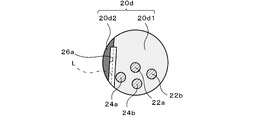
- the in-shaft region 20d is divided into first and second divided regions 20d1 and 20d2 by the axis L of the elongated groove 26a (the same as the axis of the elongated hole 26 and a straight line deviating from the diametrical direction of the ceramic plate 20). ..
- the first divided region 20d1 is shown by coarse hatching
- the second divided region 20d2 is shown by fine hatching.
- the area of the first divided region 20d1 is larger than the area of the second divided region 20d2.
- the terminals 22a, 22b, 24a, 24b are collectively provided in the first divided region 20d1 having a large area (excluding the long groove 26a). Further, each of the terminals 22a, 22b, 24a, 24b is arranged at a position where electrical insulation can be maintained.
- the thermocouple guide 32 is a tubular member made of metal (for example, stainless steel) having a guide hole 32a as shown in FIG.
- the thermocouple guide 32 includes a vertical portion 33 that extends in the vertical direction with respect to the wafer mounting surface 20a, and a curved portion 34 that changes from the vertical direction to the horizontal direction.
- the outer diameter of the vertical portion 33 is larger than the outer diameter of the curved portion 34, but the inner diameter of the vertical portion 33 is the same as the inner diameter of the curved portion 34.
- the outer diameter of the vertical portion 33 and the outer diameter of the curved portion 34 may be the same.
- the radius of curvature R of the curved portion 34 is not particularly limited, but is, for example, about 30 mm.
- the outer peripheral thermocouple 50 is inserted through the guide hole 32a of the thermocouple guide 32 (see FIG. 2).
- the tip of the curved portion 34 may be simply fitted into the long groove 26a, or may be bonded or adhered to the long groove 26a.
- the thermocouple guide 32 may be made of an electrically insulating material such as ceramic.
- Power supply rods 44a and 44b connected to the terminals 24a and 24b, respectively, are arranged.
- an inner peripheral side thermocouple 48 for measuring the temperature near the center of the ceramic plate 20 and an outer peripheral side thermocouple 50 for measuring the temperature near the outer periphery of the ceramic plate 20 are also arranged. ing.
- the inner peripheral thermocouple 48 is inserted into a recess 49 provided in the back surface 20b of the ceramic plate 20, and the temperature measuring portion 48a at the tip is in contact with the ceramic plate 20.
- the recess 49 is provided at a position where it does not interfere with the terminals 22a, 22b, 24a, 24b and the long groove 26a.
- the outer peripheral thermocouple 50 is a sheath thermocouple, passes through the guide hole 32 a of the thermocouple guide 32 and the elongated hole 26, and the temperature measuring unit 50 a at the tip reaches the end position E of the elongated hole 26.
- the ceramic heater 10 is installed in a vacuum chamber (not shown), and the wafer W is mounted on the wafer mounting surface 20a of the ceramic heater 10. Then, the electric power supplied to the inner resistance heater 22 is adjusted so that the temperature detected by the inner thermocouple 48 becomes a predetermined inner target temperature, and the outer thermocouple 50 detects the temperature. The electric power supplied to the outer resistance heating element 24 is adjusted so that the determined temperature becomes the predetermined outer target temperature. As a result, the temperature of the wafer W is controlled to a desired temperature. Then, the inside of the vacuum chamber is set to a vacuum atmosphere or a reduced pressure atmosphere, plasma is generated in the vacuum chamber, and the wafer W is subjected to CVD film formation or etching using the plasma.
- the first and second divided regions 20d1 and 20d2 are divided by the axis L of the elongated groove 26a (the same as the axis of the elongated hole 26).
- the axis L is a straight line in a direction deviating from the diametrical direction of the ceramic plate 20. Therefore, one first divided region 20d1 has a larger area than the other second divided region 20d2.
- the terminals 22a, 22b, 24a, 24b are collectively provided in the first divided region 20d1 having a large area.
- thermocouple guide 32 it is possible to collectively arrange the accessory components including the plurality of terminals 22a, 22b, 24a, 24b and increase the degree of freedom in the arrangement.
- the terminals 22a, 22b, 24a, 24b collectively, it is easy to bundle the wirings from the terminals 22a, 22b, 24a, 24b to the external device.
- auxiliary components such as the inner peripheral side thermocouple 48 other than the terminals 22a, 22b, 24a, 24b for supplying electric power to the resistance heating elements 22, 24 are located in the area surrounded by the terminals 22a, 22b, 24a, 24b. not exist.
- the power supply rods 42a, 42b, 44a, 44b are joined to the terminals 22a, 22b, 24a, 24b exposed on the back surface 20b of the ceramic plate 20, respectively, and the back surface 20b is tubular.
- the procedure of attaching the thermocouple guide 32 after joining the shaft 40 is adopted, it is not necessary to pass the thermocouple guide 32 between the power feeding rods, and thus the attachment is easy.
- auxiliary components such as the terminals 22a, 22b, 24a, 24b are collectively provided in the first divided region 20d1 having the larger area, they can be easily arranged at the position where the electrical insulation can be maintained. be able to.
- the length of the long groove 26a which is the inlet portion of the long hole 26, is determined to be equal to or longer than the length of the tip portion of the curved portion 34 of the thermocouple guide 32 of the thermocouple guide 32, which is disposed in the long groove 26a. Has been. Therefore, the thermocouple guide 32 can be easily set.
- the width of the long groove 26a can be reduced.
- the thermocouple guide 32 may include a horizontal portion 35 connected to the outlet of the bending portion 34 and extending in the horizontal direction with respect to the wafer mounting surface 20a, as shown in FIG. By doing so, the outer peripheral thermocouple 50 can be guided to the elongated hole 26 more smoothly. Further, in the thermocouple guide 32 having such a horizontal portion 35, the portion arranged in the long groove 26a becomes long. Therefore, it is preferable to set the length of the long groove 26a according to it.
- the temperature measuring unit 50a of the outer peripheral side thermocouple 50 in the elongated hole 26 has a width of the outer peripheral side resistance heating element 24 when viewed from the back surface 20b (that is, the coil width w as shown in FIG. 8). You may arrange so that it may fit in the bracket.
- the resistance heating element 24 on the outer peripheral side is not a coil shape but a ribbon shape (elongated flat plate shape), it may be arranged so as to fit within the width of the ribbon. By doing so, the temperature change of the resistance heating element 24 on the outer peripheral side can be detected by the temperature measuring unit 50a of the thermocouple 50 on the outer peripheral side with good response.
- the resistance heating elements 22 and 24 have a coil shape.
- the resistance heating elements 22 and 24 are not particularly limited to the coil shape, and may have a print pattern, a ribbon shape, a mesh shape, or the like. Good.
- the ceramic plate 20 may include electrostatic electrodes or RF electrodes in addition to the resistance heating elements 22 and 24.
- a terminal (one of accessory parts) of the electrostatic electrode is provided in the first divided region 20d1 of the ceramic plate 20.
- a terminal (one of accessory components) of the RF electrode is provided in the first divided region 20d1 of the ceramic plate 20.
- the length of the thermocouple guide 32 in the vertical direction is set to be substantially the same as the height of the tubular shaft 40, but it may be shorter or longer than the height of the tubular shaft 40.
- the inner peripheral side zone Z1 may be divided into a plurality of inner peripheral side small zones, and the resistance heating element may be routed in a single stroke for each inner peripheral side small zone.
- the outer peripheral side zone Z2 may be divided into a plurality of outer peripheral side small zones, and the resistance heating element may be laid out in a single stroke for each outer peripheral side small zone.
- the number of terminals increases according to the number of small zones. However, since these terminals are collectively provided in the first divided region 20d1 having a large area, it is relatively easy to arrange them even if the number of terminals is large. You can
- the power supply rods 42a, 42b, 44a, 44b are joined to the terminals 22a, 22b, 24a, 24b of the ceramic plate 20, respectively, and the tubular shaft 40 is joined to the back surface 20b of the ceramic plate 20, although the procedure for attaching the thermocouple guide 32 is illustrated, the attachment procedure is not limited to this. For example, after joining the tubular shaft 40 to the back surface 20b of the ceramic plate 20 and attaching the thermocouple guide 32, the power supply rods 42a, 42b, 44a and 44b are joined to the terminals 22a, 22b, 24a and 24b, respectively. Good.
- the gap G between the long groove 26a and the accessory parts is 2 mm or more. By doing so, it is possible to prevent the space between the long groove 26a and the accessory component from being too narrow and to prevent the ceramic plate 20 from being cracked.
- the present invention can be used, for example, as a member for a semiconductor manufacturing apparatus used for processing a wafer.
- thermocouple guide 32a guide hole, 33 vertical portion, 34 curved portion, 35 horizontal portion, 40 tubular shaft, 42a, 42b, 44a, 44b power supply rod, 48 inner circumference side thermocouple, 48a temperature measuring section, 49 recess, 50 outer circumference side thermocouple, 50a temperature measuring section, 410 ceramic heater, 420 ceramic plate, 426 thermocouple passage, 426a slit, 432 thermoelectric Pair guide, 440 straight shaft, 450 outer peripheral thermocouple, L axis line, P1 upper plate, P2 lower plate, S origin, E end position, W wafer, Z1 inner peripheral zone, Z2 outer peripheral zone.
Landscapes
- Chemical & Material Sciences (AREA)
- Engineering & Computer Science (AREA)
- Ceramic Engineering (AREA)
- Inorganic Chemistry (AREA)
- Resistance Heating (AREA)
- Surface Heating Bodies (AREA)
Abstract
Description
ウエハ載置面を有する円盤状のセラミックプレートと、
前記セラミックプレートのうち前記ウエハ載置面とは反対側の裏面に接合された筒状シャフトと、
前記セラミックプレートの内周部に埋設された内周側抵抗発熱体と、
前記セラミックプレートの外周部に埋設された外周側抵抗発熱体と、
前記セラミックプレートの前記裏面のうち前記筒状シャフトの内側であるシャフト内領域と、
前記セラミックプレートの直径方向から外れた方向に沿って設けられ、前記シャフト内領域から前記セラミックプレートの外周部の所定位置に至る長穴と、
前記シャフト内領域に設けられ、前記内周側抵抗発熱体の一対の端子及び前記外周側抵抗発熱体の一対の端子を含む付帯部品と、
を備え、
前記長穴のうち前記シャフト内領域を通過する部分は、長溝になっており、
前記付帯部品は、前記シャフト内領域のうち前記長溝の軸線によって分割された2つの分割領域のうち面積の大きい方の分割領域に集約して設けられている、
ものである。
Claims (10)
- ウエハ載置面を有する円盤状のセラミックプレートと、
前記セラミックプレートのうち前記ウエハ載置面とは反対側の裏面に接合された筒状シャフトと、
前記セラミックプレートの内周部に埋設された内周側抵抗発熱体と、
前記セラミックプレートの外周部に埋設された外周側抵抗発熱体と、
前記セラミックプレートの前記裏面のうち前記筒状シャフトの内側であるシャフト内領域と、
前記セラミックプレートの直径方向から外れた方向に沿って設けられ、前記シャフト内領域から前記セラミックプレートの外周部の所定位置に至る長穴と、
前記シャフト内領域に設けられ、前記内周側抵抗発熱体の一対の端子及び前記外周側抵抗発熱体の一対の端子を含む付帯部品と、
を備え、
前記長穴のうち前記シャフト内領域を通過する部分は、長溝になっており、
前記付帯部品は、前記シャフト内領域のうち前記長溝の軸線によって分割された2つの分割領域のうち面積の大きい方の分割領域に集約して設けられている、
セラミックヒータ。 - 前記付帯部品のうち前記内周側及び前記外周側抵抗発熱体の各端子以外のものは、前記内周側及び前記外周側抵抗発熱体の各端子によって囲まれた領域に存在しない、
請求項1に記載のセラミックヒータ。 - 前記長穴は、熱電対を挿入する熱電対挿入用長穴である、
請求項1又は2に記載のセラミックヒータ。 - 前記長溝は、前記ウエハ載置面に対して垂直方向から水平方向に転換する湾曲部を備えた筒状の熱電対ガイドを配置するために用いられる、
請求項1~3のいずれか1項に記載のセラミックヒータ。 - 前記長溝の長さは、前記熱電対ガイドの前記湾曲部のうち前記長溝に配置される先端部分の長さ以上となるように定められている、
請求項4に記載のセラミックヒータ。 - 前記熱電対ガイドの前記湾曲部の外径は、前記垂直部の外径よりも小さい、
請求項5に記載のセラミックヒータ。 - 請求項4~6のいずれか1項に記載のセラミックヒータであって、
前記長溝に配置された前記熱電対ガイドを備える、
セラミックヒータ。 - 請求項7に記載のセラミックヒータであって、
前記熱電対ガイド及び前記長穴に挿入された熱電対を備える、
セラミックヒータ。 - 前記セラミックプレートを前記裏面からみたときに前記熱電対の測温部が前記外周側抵抗発熱体の幅の中に収まるように配置されている、
請求項8に記載のセラミックヒータ。 - 前記長溝と前記付帯部品との間隔は、2mm以上である、
請求項1~9のいずれか1項に記載のセラミックヒータ。
Priority Applications (4)
| Application Number | Priority Date | Filing Date | Title |
|---|---|---|---|
| CN201980010581.8A CN111656860B (zh) | 2018-12-20 | 2019-12-10 | 陶瓷加热器 |
| JP2020526164A JP6775099B1 (ja) | 2018-12-20 | 2019-12-10 | セラミックヒータ |
| KR1020217008367A KR102558722B1 (ko) | 2018-12-20 | 2019-12-10 | 세라믹 히터 |
| US17/208,095 US11895742B2 (en) | 2018-12-20 | 2021-03-22 | Ceramic heater |
Applications Claiming Priority (2)
| Application Number | Priority Date | Filing Date | Title |
|---|---|---|---|
| JP2018-238225 | 2018-12-20 | ||
| JP2018238225 | 2018-12-20 |
Related Child Applications (1)
| Application Number | Title | Priority Date | Filing Date |
|---|---|---|---|
| US17/208,095 Continuation US11895742B2 (en) | 2018-12-20 | 2021-03-22 | Ceramic heater |
Publications (1)
| Publication Number | Publication Date |
|---|---|
| WO2020129754A1 true WO2020129754A1 (ja) | 2020-06-25 |
Family
ID=71102138
Family Applications (1)
| Application Number | Title | Priority Date | Filing Date |
|---|---|---|---|
| PCT/JP2019/048313 Ceased WO2020129754A1 (ja) | 2018-12-20 | 2019-12-10 | セラミックヒータ |
Country Status (6)
| Country | Link |
|---|---|
| US (1) | US11895742B2 (ja) |
| JP (1) | JP6775099B1 (ja) |
| KR (1) | KR102558722B1 (ja) |
| CN (1) | CN111656860B (ja) |
| TW (1) | TWI814962B (ja) |
| WO (1) | WO2020129754A1 (ja) |
Cited By (1)
| Publication number | Priority date | Publication date | Assignee | Title |
|---|---|---|---|---|
| WO2025079175A1 (ja) * | 2023-10-11 | 2025-04-17 | 日本碍子株式会社 | セラミックサセプタ |
Families Citing this family (2)
| Publication number | Priority date | Publication date | Assignee | Title |
|---|---|---|---|---|
| USD1065275S1 (en) * | 2020-09-18 | 2025-03-04 | Ksm Component Co., Ltd. | Ceramic heater |
| KR102900048B1 (ko) * | 2023-11-16 | 2025-12-16 | 주식회사 미코세라믹스 | 세라믹 히터 |
Citations (4)
| Publication number | Priority date | Publication date | Assignee | Title |
|---|---|---|---|---|
| JP3156031U (ja) * | 2009-09-29 | 2009-12-10 | 日本碍子株式会社 | セラミックスヒーター |
| JP2012080103A (ja) * | 2010-10-01 | 2012-04-19 | Ngk Insulators Ltd | サセプター及びその製法 |
| JP2012160368A (ja) * | 2011-02-01 | 2012-08-23 | Nihon Ceratec Co Ltd | セラミックスヒータ及びその製造方法 |
| WO2018163935A1 (ja) * | 2017-03-06 | 2018-09-13 | 日本碍子株式会社 | ウエハ支持台 |
Family Cites Families (24)
| Publication number | Priority date | Publication date | Assignee | Title |
|---|---|---|---|---|
| JP2001247382A (ja) * | 2000-03-06 | 2001-09-11 | Ibiden Co Ltd | セラミック基板 |
| US6444957B1 (en) * | 2000-04-26 | 2002-09-03 | Sumitomo Osaka Cement Co., Ltd | Heating apparatus |
| CN1460094A (zh) * | 2001-04-12 | 2003-12-03 | 揖斐电株式会社 | 陶瓷接合体、其制造方法以及半导体晶片用陶瓷结构体 |
| CN100346462C (zh) * | 2002-04-15 | 2007-10-31 | 住友电气工业株式会社 | 用于加工设备的工件固定器和使用该固定器的加工设备 |
| JP2006127883A (ja) * | 2004-10-28 | 2006-05-18 | Kyocera Corp | ヒータ及びウェハ加熱装置 |
| KR100584189B1 (ko) * | 2005-03-16 | 2006-05-29 | 동경 엘렉트론 주식회사 | 기판가열기능을 구비한 기판 탑재 기구 및 기판 처리 장치 |
| JP4756695B2 (ja) * | 2006-02-20 | 2011-08-24 | コバレントマテリアル株式会社 | 面状ヒータ |
| JP4450106B1 (ja) * | 2008-03-11 | 2010-04-14 | 東京エレクトロン株式会社 | 載置台構造及び処理装置 |
| JP5239988B2 (ja) * | 2009-03-24 | 2013-07-17 | 東京エレクトロン株式会社 | 載置台構造及び処理装置 |
| KR101357928B1 (ko) * | 2010-09-24 | 2014-02-03 | 엔지케이 인슐레이터 엘티디 | 반도체 제조 장치 부재 |
| EP2973659A4 (en) * | 2013-03-15 | 2016-11-09 | Component Re Engineering Company Inc | MORE ZONE HEATER |
| JP6084906B2 (ja) * | 2013-07-11 | 2017-02-22 | 日本碍子株式会社 | セラミックヒータ |
| CN104465453B (zh) * | 2013-09-20 | 2018-10-30 | 住友电气工业株式会社 | 等离子体cvd装置用的晶片加热器 |
| CN104582019B (zh) * | 2013-10-15 | 2019-01-04 | 住友电气工业株式会社 | 用于半导体制造装置的陶瓷加热器 |
| TWI654332B (zh) * | 2014-07-02 | 2019-03-21 | Applied Materials, Inc. | 用於電漿處理的多區域基座 |
| JP6463938B2 (ja) * | 2014-10-08 | 2019-02-06 | 日本特殊陶業株式会社 | 静電チャック |
| JP6690918B2 (ja) * | 2015-10-16 | 2020-04-28 | 日本特殊陶業株式会社 | 加熱部材、静電チャック、及びセラミックヒータ |
| JP2017091956A (ja) * | 2015-11-16 | 2017-05-25 | 京セラ株式会社 | セラミックヒータ |
| CN108476558B (zh) * | 2016-01-27 | 2021-02-09 | 京瓷株式会社 | 加热器 |
| JP6715699B2 (ja) * | 2016-06-27 | 2020-07-01 | 日本特殊陶業株式会社 | セラミックスヒータ |
| WO2018030433A1 (ja) * | 2016-08-10 | 2018-02-15 | 日本碍子株式会社 | セラミックヒータ |
| US10679873B2 (en) * | 2016-09-30 | 2020-06-09 | Ngk Spark Plug Co., Ltd. | Ceramic heater |
| JP7016347B2 (ja) * | 2017-03-02 | 2022-02-04 | 日本碍子株式会社 | ウエハ加熱装置 |
| SG11202007857XA (en) * | 2018-02-09 | 2020-09-29 | Applied Materials Inc | Semiconductor processing apparatus having improved temperature control |
-
2019
- 2019-12-10 WO PCT/JP2019/048313 patent/WO2020129754A1/ja not_active Ceased
- 2019-12-10 JP JP2020526164A patent/JP6775099B1/ja active Active
- 2019-12-10 CN CN201980010581.8A patent/CN111656860B/zh active Active
- 2019-12-10 KR KR1020217008367A patent/KR102558722B1/ko active Active
- 2019-12-13 TW TW108145724A patent/TWI814962B/zh active
-
2021
- 2021-03-22 US US17/208,095 patent/US11895742B2/en active Active
Patent Citations (4)
| Publication number | Priority date | Publication date | Assignee | Title |
|---|---|---|---|---|
| JP3156031U (ja) * | 2009-09-29 | 2009-12-10 | 日本碍子株式会社 | セラミックスヒーター |
| JP2012080103A (ja) * | 2010-10-01 | 2012-04-19 | Ngk Insulators Ltd | サセプター及びその製法 |
| JP2012160368A (ja) * | 2011-02-01 | 2012-08-23 | Nihon Ceratec Co Ltd | セラミックスヒータ及びその製造方法 |
| WO2018163935A1 (ja) * | 2017-03-06 | 2018-09-13 | 日本碍子株式会社 | ウエハ支持台 |
Cited By (3)
| Publication number | Priority date | Publication date | Assignee | Title |
|---|---|---|---|---|
| WO2025079175A1 (ja) * | 2023-10-11 | 2025-04-17 | 日本碍子株式会社 | セラミックサセプタ |
| JP7686149B1 (ja) * | 2023-10-11 | 2025-05-30 | 日本碍子株式会社 | セラミックサセプタ |
| US12700577B2 (en) | 2023-10-11 | 2026-08-04 | Ngk Insulators, Ltd. | Ceramic susceptor |
Also Published As
| Publication number | Publication date |
|---|---|
| JPWO2020129754A1 (ja) | 2021-02-15 |
| TW202038677A (zh) | 2020-10-16 |
| KR20210045473A (ko) | 2021-04-26 |
| KR102558722B1 (ko) | 2023-07-24 |
| TWI814962B (zh) | 2023-09-11 |
| US11895742B2 (en) | 2024-02-06 |
| CN111656860A (zh) | 2020-09-11 |
| CN111656860B (zh) | 2022-05-27 |
| US20210212172A1 (en) | 2021-07-08 |
| JP6775099B1 (ja) | 2020-10-28 |
Similar Documents
| Publication | Publication Date | Title |
|---|---|---|
| JP6743325B1 (ja) | セラミックヒータ | |
| CN113286385B (zh) | 陶瓷加热器 | |
| CN113543380B (zh) | 陶瓷加热器及其制法 | |
| CN113056961B (zh) | 陶瓷加热器 | |
| JP6775099B1 (ja) | セラミックヒータ | |
| CN110235237A (zh) | 晶圆支撑台 | |
| KR20210098857A (ko) | 세라믹 히터 및 그의 제법 | |
| CN113811029B (zh) | 热电偶引导件及陶瓷加热器 | |
| TWI811694B (zh) | 熱電偶導件以及陶瓷加熱器 | |
| US11924929B2 (en) | Ceramic heater and thermocouple guide | |
| CN113207199A (zh) | 陶瓷加热器 |
Legal Events
| Date | Code | Title | Description |
|---|---|---|---|
| ENP | Entry into the national phase |
Ref document number: 2020526164 Country of ref document: JP Kind code of ref document: A |
|
| 121 | Ep: the epo has been informed by wipo that ep was designated in this application |
Ref document number: 19899049 Country of ref document: EP Kind code of ref document: A1 |
|
| ENP | Entry into the national phase |
Ref document number: 20217008367 Country of ref document: KR Kind code of ref document: A |
|
| NENP | Non-entry into the national phase |
Ref country code: DE |
|
| 122 | Ep: pct application non-entry in european phase |
Ref document number: 19899049 Country of ref document: EP Kind code of ref document: A1 |