WO2020121780A1 - 車両の制御装置及び車両の制御方法 - Google Patents
車両の制御装置及び車両の制御方法 Download PDFInfo
- Publication number
- WO2020121780A1 WO2020121780A1 PCT/JP2019/045752 JP2019045752W WO2020121780A1 WO 2020121780 A1 WO2020121780 A1 WO 2020121780A1 JP 2019045752 W JP2019045752 W JP 2019045752W WO 2020121780 A1 WO2020121780 A1 WO 2020121780A1
- Authority
- WO
- WIPO (PCT)
- Prior art keywords
- vehicle
- lockup clutch
- coast stop
- stop control
- variator
- Prior art date
- Legal status (The legal status is an assumption and is not a legal conclusion. Google has not performed a legal analysis and makes no representation as to the accuracy of the status listed.)
- Ceased
Links
Images


Classifications
-
- B—PERFORMING OPERATIONS; TRANSPORTING
- B60—VEHICLES IN GENERAL
- B60W—CONJOINT CONTROL OF VEHICLE SUB-UNITS OF DIFFERENT TYPE OR DIFFERENT FUNCTION; CONTROL SYSTEMS SPECIALLY ADAPTED FOR HYBRID VEHICLES; ROAD VEHICLE DRIVE CONTROL SYSTEMS FOR PURPOSES NOT RELATED TO THE CONTROL OF A PARTICULAR SUB-UNIT
- B60W30/00—Purposes of road vehicle drive control systems not related to the control of a particular sub-unit, e.g. of systems using conjoint control of vehicle sub-units
- B60W30/18—Propelling the vehicle
- B60W30/18009—Propelling the vehicle related to particular drive situations
- B60W30/18072—Coasting
-
- B—PERFORMING OPERATIONS; TRANSPORTING
- B60—VEHICLES IN GENERAL
- B60W—CONJOINT CONTROL OF VEHICLE SUB-UNITS OF DIFFERENT TYPE OR DIFFERENT FUNCTION; CONTROL SYSTEMS SPECIALLY ADAPTED FOR HYBRID VEHICLES; ROAD VEHICLE DRIVE CONTROL SYSTEMS FOR PURPOSES NOT RELATED TO THE CONTROL OF A PARTICULAR SUB-UNIT
- B60W10/00—Conjoint control of vehicle sub-units of different type or different function
- B60W10/02—Conjoint control of vehicle sub-units of different type or different function including control of driveline clutches
- B60W10/024—Conjoint control of vehicle sub-units of different type or different function including control of driveline clutches including control of torque converters
- B60W10/026—Conjoint control of vehicle sub-units of different type or different function including control of driveline clutches including control of torque converters of lock-up clutches
-
- B—PERFORMING OPERATIONS; TRANSPORTING
- B60—VEHICLES IN GENERAL
- B60W—CONJOINT CONTROL OF VEHICLE SUB-UNITS OF DIFFERENT TYPE OR DIFFERENT FUNCTION; CONTROL SYSTEMS SPECIALLY ADAPTED FOR HYBRID VEHICLES; ROAD VEHICLE DRIVE CONTROL SYSTEMS FOR PURPOSES NOT RELATED TO THE CONTROL OF A PARTICULAR SUB-UNIT
- B60W10/00—Conjoint control of vehicle sub-units of different type or different function
- B60W10/10—Conjoint control of vehicle sub-units of different type or different function including control of change-speed gearings
- B60W10/101—Infinitely variable gearings
- B60W10/107—Infinitely variable gearings with endless flexible members
-
- B—PERFORMING OPERATIONS; TRANSPORTING
- B60—VEHICLES IN GENERAL
- B60W—CONJOINT CONTROL OF VEHICLE SUB-UNITS OF DIFFERENT TYPE OR DIFFERENT FUNCTION; CONTROL SYSTEMS SPECIALLY ADAPTED FOR HYBRID VEHICLES; ROAD VEHICLE DRIVE CONTROL SYSTEMS FOR PURPOSES NOT RELATED TO THE CONTROL OF A PARTICULAR SUB-UNIT
- B60W30/00—Purposes of road vehicle drive control systems not related to the control of a particular sub-unit, e.g. of systems using conjoint control of vehicle sub-units
- B60W30/18—Propelling the vehicle
- B60W30/188—Controlling power parameters of the driveline, e.g. determining the required power
-
- F—MECHANICAL ENGINEERING; LIGHTING; HEATING; WEAPONS; BLASTING
- F02—COMBUSTION ENGINES; HOT-GAS OR COMBUSTION-PRODUCT ENGINE PLANTS
- F02D—CONTROLLING COMBUSTION ENGINES
- F02D29/00—Controlling engines, such controlling being peculiar to the devices driven thereby, the devices being other than parts or accessories essential to engine operation, e.g. controlling of engines by signals external thereto
- F02D29/02—Controlling engines, such controlling being peculiar to the devices driven thereby, the devices being other than parts or accessories essential to engine operation, e.g. controlling of engines by signals external thereto peculiar to engines driving vehicles; peculiar to engines driving variable pitch propellers
-
- F—MECHANICAL ENGINEERING; LIGHTING; HEATING; WEAPONS; BLASTING
- F02—COMBUSTION ENGINES; HOT-GAS OR COMBUSTION-PRODUCT ENGINE PLANTS
- F02D—CONTROLLING COMBUSTION ENGINES
- F02D41/00—Electrical control of supply of combustible mixture or its constituents
- F02D41/02—Circuit arrangements for generating control signals
- F02D41/021—Introducing corrections for particular conditions exterior to the engine
- F02D41/0215—Introducing corrections for particular conditions exterior to the engine in relation with elements of the transmission
- F02D41/022—Introducing corrections for particular conditions exterior to the engine in relation with elements of the transmission in relation with the clutch status
-
- F—MECHANICAL ENGINEERING; LIGHTING; HEATING; WEAPONS; BLASTING
- F02—COMBUSTION ENGINES; HOT-GAS OR COMBUSTION-PRODUCT ENGINE PLANTS
- F02D—CONTROLLING COMBUSTION ENGINES
- F02D41/00—Electrical control of supply of combustible mixture or its constituents
- F02D41/02—Circuit arrangements for generating control signals
- F02D41/04—Introducing corrections for particular operating conditions
- F02D41/042—Introducing corrections for particular operating conditions for stopping the engine
-
- F—MECHANICAL ENGINEERING; LIGHTING; HEATING; WEAPONS; BLASTING
- F16—ENGINEERING ELEMENTS AND UNITS; GENERAL MEASURES FOR PRODUCING AND MAINTAINING EFFECTIVE FUNCTIONING OF MACHINES OR INSTALLATIONS; THERMAL INSULATION IN GENERAL
- F16H—GEARING
- F16H59/00—Control inputs to control units of change-speed- or reversing-gearings for conveying rotary motion
- F16H59/36—Inputs being a function of speed
- F16H59/46—Inputs being a function of speed dependent on a comparison between speeds
-
- F—MECHANICAL ENGINEERING; LIGHTING; HEATING; WEAPONS; BLASTING
- F16—ENGINEERING ELEMENTS AND UNITS; GENERAL MEASURES FOR PRODUCING AND MAINTAINING EFFECTIVE FUNCTIONING OF MACHINES OR INSTALLATIONS; THERMAL INSULATION IN GENERAL
- F16H—GEARING
- F16H61/00—Control functions within control units of change-speed- or reversing-gearings for conveying rotary motion ; Control of exclusively fluid gearing, friction gearing, gearings with endless flexible members or other particular types of gearing
- F16H61/14—Control of torque converter lock-up clutches
- F16H61/143—Control of torque converter lock-up clutches using electric control means
-
- F—MECHANICAL ENGINEERING; LIGHTING; HEATING; WEAPONS; BLASTING
- F16—ENGINEERING ELEMENTS AND UNITS; GENERAL MEASURES FOR PRODUCING AND MAINTAINING EFFECTIVE FUNCTIONING OF MACHINES OR INSTALLATIONS; THERMAL INSULATION IN GENERAL
- F16H—GEARING
- F16H61/00—Control functions within control units of change-speed- or reversing-gearings for conveying rotary motion ; Control of exclusively fluid gearing, friction gearing, gearings with endless flexible members or other particular types of gearing
- F16H61/66—Control functions within control units of change-speed- or reversing-gearings for conveying rotary motion ; Control of exclusively fluid gearing, friction gearing, gearings with endless flexible members or other particular types of gearing specially adapted for continuously variable gearings
- F16H61/662—Control functions within control units of change-speed- or reversing-gearings for conveying rotary motion ; Control of exclusively fluid gearing, friction gearing, gearings with endless flexible members or other particular types of gearing specially adapted for continuously variable gearings with endless flexible members
-
- B—PERFORMING OPERATIONS; TRANSPORTING
- B60—VEHICLES IN GENERAL
- B60W—CONJOINT CONTROL OF VEHICLE SUB-UNITS OF DIFFERENT TYPE OR DIFFERENT FUNCTION; CONTROL SYSTEMS SPECIALLY ADAPTED FOR HYBRID VEHICLES; ROAD VEHICLE DRIVE CONTROL SYSTEMS FOR PURPOSES NOT RELATED TO THE CONTROL OF A PARTICULAR SUB-UNIT
- B60W2510/00—Input parameters relating to a particular sub-units
- B60W2510/02—Clutches
- B60W2510/0208—Clutch engagement state, e.g. engaged or disengaged
- B60W2510/0233—Clutch engagement state, e.g. engaged or disengaged of torque converter lock-up clutch
-
- B—PERFORMING OPERATIONS; TRANSPORTING
- B60—VEHICLES IN GENERAL
- B60W—CONJOINT CONTROL OF VEHICLE SUB-UNITS OF DIFFERENT TYPE OR DIFFERENT FUNCTION; CONTROL SYSTEMS SPECIALLY ADAPTED FOR HYBRID VEHICLES; ROAD VEHICLE DRIVE CONTROL SYSTEMS FOR PURPOSES NOT RELATED TO THE CONTROL OF A PARTICULAR SUB-UNIT
- B60W2510/00—Input parameters relating to a particular sub-units
- B60W2510/02—Clutches
- B60W2510/0241—Clutch slip, i.e. difference between input and output speeds
-
- B—PERFORMING OPERATIONS; TRANSPORTING
- B60—VEHICLES IN GENERAL
- B60W—CONJOINT CONTROL OF VEHICLE SUB-UNITS OF DIFFERENT TYPE OR DIFFERENT FUNCTION; CONTROL SYSTEMS SPECIALLY ADAPTED FOR HYBRID VEHICLES; ROAD VEHICLE DRIVE CONTROL SYSTEMS FOR PURPOSES NOT RELATED TO THE CONTROL OF A PARTICULAR SUB-UNIT
- B60W2510/00—Input parameters relating to a particular sub-units
- B60W2510/02—Clutches
- B60W2510/0275—Clutch torque
-
- B—PERFORMING OPERATIONS; TRANSPORTING
- B60—VEHICLES IN GENERAL
- B60W—CONJOINT CONTROL OF VEHICLE SUB-UNITS OF DIFFERENT TYPE OR DIFFERENT FUNCTION; CONTROL SYSTEMS SPECIALLY ADAPTED FOR HYBRID VEHICLES; ROAD VEHICLE DRIVE CONTROL SYSTEMS FOR PURPOSES NOT RELATED TO THE CONTROL OF A PARTICULAR SUB-UNIT
- B60W2510/00—Input parameters relating to a particular sub-units
- B60W2510/06—Combustion engines, Gas turbines
- B60W2510/0638—Engine speed
- B60W2510/0647—Coasting condition
-
- B—PERFORMING OPERATIONS; TRANSPORTING
- B60—VEHICLES IN GENERAL
- B60W—CONJOINT CONTROL OF VEHICLE SUB-UNITS OF DIFFERENT TYPE OR DIFFERENT FUNCTION; CONTROL SYSTEMS SPECIALLY ADAPTED FOR HYBRID VEHICLES; ROAD VEHICLE DRIVE CONTROL SYSTEMS FOR PURPOSES NOT RELATED TO THE CONTROL OF A PARTICULAR SUB-UNIT
- B60W2510/00—Input parameters relating to a particular sub-units
- B60W2510/06—Combustion engines, Gas turbines
- B60W2510/0657—Engine torque
-
- B—PERFORMING OPERATIONS; TRANSPORTING
- B60—VEHICLES IN GENERAL
- B60W—CONJOINT CONTROL OF VEHICLE SUB-UNITS OF DIFFERENT TYPE OR DIFFERENT FUNCTION; CONTROL SYSTEMS SPECIALLY ADAPTED FOR HYBRID VEHICLES; ROAD VEHICLE DRIVE CONTROL SYSTEMS FOR PURPOSES NOT RELATED TO THE CONTROL OF A PARTICULAR SUB-UNIT
- B60W2510/00—Input parameters relating to a particular sub-units
- B60W2510/10—Change speed gearings
- B60W2510/1005—Transmission ratio engaged
-
- B—PERFORMING OPERATIONS; TRANSPORTING
- B60—VEHICLES IN GENERAL
- B60Y—INDEXING SCHEME RELATING TO ASPECTS CROSS-CUTTING VEHICLE TECHNOLOGY
- B60Y2300/00—Purposes or special features of road vehicle drive control systems
- B60Y2300/18—Propelling the vehicle
- B60Y2300/18008—Propelling the vehicle related to particular drive situations
- B60Y2300/18066—Coasting
- B60Y2300/18083—Coasting without torque flow between driveshaft and engine, e.g. with clutch disengaged or transmission in neutral
-
- Y—GENERAL TAGGING OF NEW TECHNOLOGICAL DEVELOPMENTS; GENERAL TAGGING OF CROSS-SECTIONAL TECHNOLOGIES SPANNING OVER SEVERAL SECTIONS OF THE IPC; TECHNICAL SUBJECTS COVERED BY FORMER USPC CROSS-REFERENCE ART COLLECTIONS [XRACs] AND DIGESTS
- Y02—TECHNOLOGIES OR APPLICATIONS FOR MITIGATION OR ADAPTATION AGAINST CLIMATE CHANGE
- Y02T—CLIMATE CHANGE MITIGATION TECHNOLOGIES RELATED TO TRANSPORTATION
- Y02T10/00—Road transport of goods or passengers
- Y02T10/60—Other road transportation technologies with climate change mitigation effect
Definitions
- the present invention relates to a vehicle control device and a vehicle control method.
- JP2012-51468A discloses a coast stop control in which the engine is automatically stopped immediately before the stop of the vehicle in order to improve fuel efficiency when the idling stop is performed while the vehicle is stopped.
- the variator's gear ratio is set to the lowest Low gear ratio. Returning is referred to as "Low returning".)
- the variator In order to change the speed of the variator, it is necessary for the variator to rotate, and it is difficult to change the speed of the variator when the variator is not rotating.
- the present invention has been made in view of such a technical problem, and an object thereof is to reliably perform Low return when performing coast stop control.
- a vehicle control device includes a drive source, a torque converter arranged downstream of the drive source and having a lockup clutch, and a variator arranged downstream of the torque converter. And a vehicle having a gear transmission. Further, the vehicle control device automatically stops the drive source during traveling of the vehicle when the permission condition including that the gear ratio of the variator is lower than the first threshold value is established during the engagement phase of the lockup clutch.
- the control unit has a control unit that executes the coast stop control, and the control unit prohibits the coast stop control when the input/output rotation difference of the torque converter is equal to or more than a predetermined value when the lockup clutch is in the engagement phase.
- FIG. 1 is a schematic configuration diagram of a vehicle according to an embodiment of the present invention.
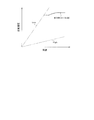
- FIG. 2 is a diagram showing an example of shift lines for controlling the automatic transmission according to the embodiment of the present invention.
- FIG. 3 is a flowchart of the course top control according to the embodiment of the present invention.
- FIG. 1 is a schematic configuration diagram of a vehicle 100.
- the vehicle 100 includes an engine 1, an automatic transmission 3 as a continuously variable transmission, an oil pump 5, drive wheels 6, and a controller 10 as a control device.
- the engine 1 is an internal combustion engine that uses gasoline, light oil, etc. as fuel, and functions as a drive source for traveling.
- the engine 1 is controlled in rotation speed, torque, etc. based on a command from the controller 10.
- the automatic transmission 3 includes a torque converter 2, a fastening element 31, a variator 30, a hydraulic control valve unit 40 (hereinafter, also simply referred to as “valve unit 40"), and oil that stores oil (operating oil). And a bread 32.
- the torque converter 2 is provided on the power transmission path between the engine 1 and the drive wheels 6.
- the torque converter 2 transmits power via fluid. Further, the torque converter 2 can enhance the power transmission efficiency of the driving force from the engine 1 by engaging the lockup clutch 2a.
- the fastening element 31 is arranged on the power transmission path between the torque converter 2 and the variator 30.
- the fastening element 31 includes a forward clutch and a reverse brake (not shown).
- the fastening element 31 is controlled by the oil whose pressure is adjusted by the valve unit 40 with the discharge pressure of the oil pump 5 as the original pressure, based on a command from the controller 10.
- a normally open wet multi-plate clutch is used as the fastening element 31.
- the variator 30 is arranged on the power transmission path between the fastening element 31 and the drive wheels 6, and changes the gear ratio steplessly according to the vehicle speed, accelerator opening, and the like.
- the variator 30 includes a primary pulley 30a, a secondary pulley 30b, and a belt 30c wound around the pulleys 30a and 30b.
- the pulley pressure acting on the primary pulley 30a and the pulley pressure acting on the secondary pulley 30b are regulated by the valve unit 40 with the discharge pressure from the oil pump 5 as the original pressure.
- the differential 12 is connected to the output shaft of the secondary pulley 30b of the variator 30 via a final reduction gear mechanism (not shown).
- Drive wheels 6 are connected to the differential 12 via a drive shaft 13.
- the oil pump 5 is driven by the rotation of the engine 1 transmitted via a belt.
- the oil pump 5 is composed of, for example, a vane pump.
- the oil pump 5 sucks up the oil stored in the oil pan 32 and supplies the oil to the valve unit 40.
- the oil supplied to the valve unit 40 is used for driving the pulleys 30a and 30b, driving the fastening element 31, and lubricating each element of the automatic transmission 3.
- the controller 10 is composed of a microcomputer including a central processing unit (CPU), a read only memory (ROM), a random access memory (RAM), and an input/output interface (I/O interface).
- the controller 10 can also be composed of a plurality of microcomputers.
- the controller 10 may be configured by an ATCU that controls the automatic transmission 3, an SCU that controls the shift range, an ECU that controls the engine 1, and the like.
- the control unit in the present embodiment is a virtual unit having a function of executing coast stop control, which will be described later, of the controller 10.
- a second rotation speed sensor 52 that detects the speed Nt
- a fourth rotation speed sensor that detects the rotation speed of the secondary pulley 30b.
- a rotation speed sensor 54 a vehicle speed sensor 55 that detects a vehicle speed V, an inhibitor switch 56 that detects a select range of the variator 30 (a state of a select lever or a select switch that switches forward, reverse, neutral and parking), and an accelerator opening APO.
- Signals from the accelerator opening sensor 57, the pedal force sensor 58 for detecting the pedal force of the brake, and the like are input.
- the controller 10 controls various operations of the engine 1 and the automatic transmission 3 based on these input signals.
- the controller 10 performs the coast stop control described below in order to suppress the fuel consumption.
- the coast stop control is a control for suppressing the fuel consumption by automatically stopping the engine 1 (coast stop) while the vehicle 100 is traveling in the low vehicle speed range.
- the fuel cut control executed when the accelerator is off is common in that the fuel supply to the engine 1 is stopped, but the lockup clutch 2a is released to set the power transmission path between the engine 1 and the drive wheels 6. The difference is that the rotation of the engine 1 is completely stopped.
- the fuel cut control executed when the accelerator is off is released when the lockup clutch 2a is released, and fuel injection is restarted to maintain the engine 1 in an independent state.
- the lockup clutch 2a is released when the lockup release line (not shown) set on the shift map is crossed from the high speed side or the high rotation side to the low speed side or the low rotation side.
- the Low return is a shift control that changes the gear ratio of the variator 30 to the Low side, that is, in the direction in which the gear ratio increases in accordance with the decrease in the vehicle speed V. For example, as shown in FIG. This is performed by downshifting the variator 30 according to the coast line shown (shift line during coast running).
- the piston thrust is determined by the pressure difference between the front and rear (front and back) of the piston (not shown). Therefore, when the oil balance is insufficient, for example, in the engagement phase of the lock-up clutch 2a, Specifically, even if the controller 10 issues an instruction to engage the lockup clutch 2a, the lockup clutch 2a may be released.
- the coast stop control is executed in such a situation, the flow rate and oil pressure of the oil discharged from the oil pump 5 may be insufficient, and the Low return may not be completed.
- FIG. 3 is a flowchart showing a control flow relating to the coast stop control in this embodiment.
- the coast stop control of this embodiment is performed by executing a program stored in advance in the controller 10.
- step S1 it is determined whether the accelerator is off. Specifically, the controller 10 determines whether or not the accelerator is off based on the accelerator opening APO detected by the accelerator opening sensor 57. If it is determined that the accelerator is off, the process proceeds to step S2. If it is determined that the accelerator is not OFF, the coast stop condition is not satisfied, so the process proceeds to END.
- step S2 it is determined whether the brake is ON. Specifically, the controller 10 determines whether or not the brake is ON, based on the pedal effort of the brake detected by the pedal effort sensor 58. If it is determined that the brake is ON, the process proceeds to step S3. Further, if it is determined that the brake is not ON, the coast stop condition is not satisfied, so the routine proceeds to END.
- step S3 it is determined whether the vehicle speed V is less than or equal to a predetermined vehicle speed V1. Specifically, the controller 10 determines, based on the vehicle speed V detected by the vehicle speed sensor 55, whether or not the vehicle speed V is equal to or lower than a predetermined vehicle speed V1. If it is determined that the vehicle speed V is equal to or lower than the predetermined vehicle speed V1, the process proceeds to step S4. Further, if it is determined that the vehicle speed V is not equal to or lower than the predetermined vehicle speed V1, the coast stop condition is not satisfied, so the routine proceeds to END.
- step S4 it is determined whether the lockup clutch 2a is in the engagement phase. Specifically, the controller 10 determines whether or not a signal for instructing the engagement of the lockup clutch 2a is output. If the signal for instructing the engagement of the lockup clutch 2a is output from the controller 10, it is determined that the lockup clutch 2a is in the engagement phase, and the process proceeds to step S5. On the other hand, if the signal for instructing the engagement of the lockup clutch 2a is not output from the controller 10, it is determined that the lockup clutch 2a is in the disengagement phase, and the process proceeds to step S8.
- the engagement phase means that the vehicle state (the relationship between the vehicle speed V and the accelerator opening APO) is in the engagement region of the lockup clutch 2a
- the release phase means the vehicle state (the vehicle speed V and the accelerator opening APO). Is in the release area of the lockup clutch 2a.
- step S5 it is determined whether the gear ratio R of the variator 30 is greater than or equal to the first threshold value R1.
- the controller 10 determines the gear ratio based on the rotation speed of the primary pulley 30a detected by the third rotation speed sensor 53 and the rotation speed of the secondary pulley 30b detected by the fourth rotation speed sensor 54. R is determined, and it is determined whether or not this gear ratio R is greater than or equal to a predetermined first threshold value R1.
- the first threshold value R1 is a threshold value when the lockup clutch 2a is in the engaged state, and is a value at which the variator 30 can surely return to the lowest Low gear ratio when the coast stop control (engine stop) is executed at this time. Is set to.
- step S6 If the gear ratio R of the variator 30 is the first threshold value R1 or more, the process proceeds to step S6. On the other hand, if the gear ratio R of the variator 30 is less than the first threshold value R1, the gear ratio R is on the High side of the first threshold value R1, and therefore the execution of the coast stop control is prohibited (go to END).
- step S6 it is determined whether the input/output rotational speed difference D is equal to or larger than a predetermined value D1.
- the pump rotation speed Np which is the rotation speed on the input side of the torque converter 2 detected by the first rotation speed sensor 51, and the rotation on the output side of the torque converter 2 detected by the second rotation speed sensor 52. It is determined whether or not the difference from the turbine rotation speed Nt, which is the speed (input/output rotation speed difference D), is equal to or greater than a predetermined value D1.
- the input/output rotational speed difference D being equal to or larger than the predetermined value D1 means that the lockup clutch 2a is released even though the controller 10 outputs the signal for instructing the engagement of the lockup clutch 2a. It will be. Therefore, by performing the determination of step S6, it is possible to accurately determine whether or not the lockup clutch 2a is engaged. If the input/output rotational speed difference D is greater than or equal to the predetermined value D1, the lockup clutch 2a is unintentionally in the released state, so execution of the coast stop control is temporarily prohibited, and the process proceeds to step S9. On the other hand, if the input/output rotation speed difference D is less than the predetermined value D1, the lockup clutch 2a is in the engaged state, and therefore the process proceeds to step S7, and coast stop control is executed.
- step S4 the flow when the lockup clutch 2a is determined to be in the disengagement phase in step S4 (when proceeding to step S8) will be described.
- step S8 it is determined whether the gear ratio R of the variator 30 is greater than or equal to the second threshold value R2.
- the controller 10 determines the gear ratio based on the rotation speed of the primary pulley 30a detected by the third rotation speed sensor 53 and the rotation speed of the secondary pulley 30b detected by the fourth rotation speed sensor 54.
- R is determined, and it is determined whether or not this gear ratio R is greater than or equal to a second threshold value R2 that is set in advance.
- the second threshold value R2 is a threshold value when the lockup clutch 2a is in the released state, and is set to a value on the Low side of the first threshold value R1.
- the second threshold value R2 is set to a value such that the variator 30 can surely return to the maximum Low gear ratio when the coast stop control is executed at this time.
- gear ratio R of the variator 30 is greater than or equal to the second threshold value R2, the gear ratio R is on the lower side of the second threshold value R2, so the process proceeds to step S7 and coast stop control is executed.
- the gear ratio R of the variator 30 is less than the second threshold value R2, the gear ratio R is on the High side of the second threshold value R2, and therefore the execution of the coast stop control is prohibited (go to END).
- step S6 the input/output rotational speed difference D is equal to or greater than the predetermined value D1 (when proceeding to step S9) will be described.
- step S9 it is determined whether the gear ratio R of the variator 30 is greater than or equal to the second threshold value R2.
- the specific determination method is the same as that in step S8, and thus the description is omitted.
- the gear ratio R of the variator 30 is greater than or equal to the second threshold value R2, the gear ratio R is on the lower side than the second threshold value R2. Execute. On the other hand, if the gear ratio R of the variator 30 is less than the second threshold value R2, the gear ratio R is higher than the second threshold value R2, and therefore the prohibition of execution of the coast stop control is continued (go to END). ).
- the permission condition for executing the coast stop control is that the gear ratio R of the variator 30 is equal to or greater than the first threshold value R1 or the second threshold value R2.
- the coast stop control is executed when the low return can be reliably executed.
- the coast stop control is prohibited when the low return cannot be executed reliably, so that the reliability of the low return is ensured. improves.
- the lockup clutch 2a when the lockup clutch 2a is in the engagement phase and the input/output rotational speed difference D of the torque converter 2 is the predetermined value D1 or more, execution of coast stop control is prohibited. As described above, in the state where the lockup clutch 2a is released, the flow rate and the oil pressure of the oil discharged from the oil pump 5 decrease earlier than in the state where the lockup clutch 2a is engaged, so the lockup clutch 2a If the coast stop control is executed in the same manner as in the state in which is fastened, the Low return may not be completed.
- the controller 10 locks the lockup clutch 2a.
- execution of coast stop control is prohibited. This can improve the certainty of Low return.
- the gear ratio R is equal to or more than the second threshold value R2
- the prohibition of execution of the coast stop control is released and the coast stop control is executed.
- the number of times the coast stop control is executed can be increased.
- the controller 10 (control device) of the present embodiment is disposed downstream of the drive source (engine 1), the drive source (engine 1), and the torque converter 2 having the lockup clutch 2a, and is disposed downstream of the torque converter 2. And a continuously variable transmission (automatic transmission 3) having the variator 30.
- the controller 10 drives the vehicle 100 while the vehicle 100 is running when a permission condition including that the gear ratio R of the variator 30 is lower than the first threshold value R1 during the engagement phase of the lockup clutch 2a is satisfied. It has a control unit (controller 10) that executes coast stop control for automatically stopping the power source (engine 1). The control unit (controller 10) prohibits the coast stop control from being executed when the input/output rotational speed difference D of the torque converter 2 is equal to or larger than the predetermined value D1 when the lockup clutch 2a is in the engagement phase.
- the gear ratio R of the variator 30 is lower than the threshold values (first threshold value R1 and second threshold value R2). It is possible to surely perform Low return.
- controller 10 executes the coast stop control when the permission condition including that the gear ratio R of the variator 30 is on the Low side of the second threshold value R2 is established during the release phase of the lockup clutch 2a.
- the second threshold value R2 is set to be lower than the first threshold value R1.
- the second threshold value R2 set to the Low side of the first threshold value R1 as the permission condition for executing the coast stop control in the release phase, the coast stop is performed even at the time of lockup release which is disadvantageous to the Low return. Control can be exercised. As a result, the frequency of execution of the coast stop control increases, so that the fuel efficiency can be improved. Further, since the threshold value is variable in consideration of the engagement state of the lockup clutch 2a, it is possible to improve the certainty of Low return.
- the controller 10 sets the gear ratio R of the variator 30 to the second value. If it is on the Low side of the threshold value R2, the prohibition of execution of the coast stop control is released.
- the execution or prohibition of the coast stop control is determined using the second threshold value R2 which is the threshold value when the lockup clutch 2a is released. As a result, the frequency of execution can be increased without lowering the certainty of returning to Low, so fuel consumption can be improved.
- the controller 10 determines whether or not coast stop is prohibited using the first threshold value R1.
- the gear ratio R becomes the second speed ratio. If the determinations in steps S4 and S8 are made in a state where the threshold value R2 is not increased, execution of coast stop control may be prohibited. Therefore, after the execution of the coast stop control is permitted during the engagement phase of the lockup clutch 2a, the controller 10 determines the prohibition of the coast stop control using the first threshold value R1. This can prevent the coast stop control from being inadvertently prohibited from being executed.
- the controller 10 determines whether or not it is in the fastening phase, but may determine whether or not it is in the release phase. Since the controller 10 outputs an instruction to release the lockup clutch 2a, the controller 10 can recognize the release phase based on this signal.
Landscapes
- Engineering & Computer Science (AREA)
- Mechanical Engineering (AREA)
- General Engineering & Computer Science (AREA)
- Transportation (AREA)
- Chemical & Material Sciences (AREA)
- Combustion & Propulsion (AREA)
- Automation & Control Theory (AREA)
- Control Of Transmission Device (AREA)
- Control Of Fluid Gearings (AREA)
- Control Of Vehicle Engines Or Engines For Specific Uses (AREA)
Abstract
コントローラは、ロックアップクラッチが締結フェーズ中にバリエータの変速比Rが第1閾値R1よりもLow側にあることを含む許可条件が成立すると、車両の走行中における駆動源(エンジン)の自動停止を行うコーストストップ制御を実行する制御部を有し、制御部は、ロックアップクラッチが締結フェーズであるときにトルクコンバータの入出力回転速度差Dが所定値D1以上の場合にはコーストストップ制御の実行を禁止する。
Description
本発明は、車両の制御装置及び車両の制御方法に関する。
JP2012-51468Aには、車両停止中にアイドリングストップを行う際に、より燃費を向上させるため、車両の停止直前にエンジン自動停止を行うコーストストップ制御が開示されている。
コーストストップ制御を行うに際して、車両の再発進性を確保するために車両の停止直前までにバリエータを最Low変速比に戻したいという要請がある(以下では、バリエータの変速比を最Low変速比に戻すことを、「Low戻し」という。)。なお、バリエータを変速させるためには、バリエータが回転している必要があり、バリエータが回転していない状況でバリエータを変速させることは困難である。
そのため、コーストストップ制御を行うタイミングによっては、Low戻しを完了できない可能性がある。このように、Low戻しを完了できない、つまり、バリエータの変速比を最Low変速比に戻っていない状態では、車両の発進性が悪化してしまうおそれがある。
本発明は、このような技術的課題に鑑みてなされたもので、コーストストップ制御を行うに際してLow戻しを確実に行うことを目的とする。
本発明のある態様によれば、車両の制御装置は、駆動源と、駆動源の下流に配置され且つロックアップクラッチを有するトルクコンバータと、トルクコンバータの下流に配置されたバリエータと、を有する無段変速機と、を有する車両を制御する。さらに、車両の制御装置は、ロックアップクラッチが締結フェーズ中にバリエータの変速比が第1閾値よりもLow側にあることを含む許可条件が成立すると、車両の走行中における駆動源の自動停止を行うコーストストップ制御を実行する制御部を有し、制御部は、ロックアップクラッチが締結フェーズであるときにトルクコンバータの入出力回転差が所定値以上の場合にはコーストストップ制御の実行を禁止する。
この態様によれば、Low戻しを確実に行うことができる。
以下、添付図面を参照しながら本発明の実施形態について説明する。
図1は、車両100の概略構成図である。車両100は、エンジン1と、無段変速機としての自動変速機3と、オイルポンプ5と、駆動輪6と、制御装置としてのコントローラ10と、を備える。
エンジン1は、ガソリン、軽油等を燃料とする内燃機関であり、走行用駆動源として機能する。エンジン1は、コントローラ10からの指令に基づいて、回転速度、トルク等が制御される。
自動変速機3は、トルクコンバータ2と、締結要素31と、バリエータ30と、油圧コントロールバルブユニット40(以下では、単に「バルブユニット40」ともいう。)と、オイル(作動油)を貯留するオイルパン32と、を備える。
トルクコンバータ2は、エンジン1と駆動輪6の間の動力伝達経路上に設けられる。トルクコンバータ2は、流体を介して動力を伝達する。また、トルクコンバータ2は、ロックアップクラッチ2aを締結することで、エンジン1からの駆動力の動力伝達効率を高めることができる。
締結要素31は、トルクコンバータ2とバリエータ30の間の動力伝達経路上に配置される。締結要素31は、図示しない前進クラッチ及び後進ブレーキを備える。締結要素31は、コントローラ10からの指令に基づき、オイルポンプ5の吐出圧を元圧としてバルブユニット40によって調圧されたオイルによって制御される。締結要素31としては、例えば、ノーマルオープンの湿式多板クラッチが用いられる。
バリエータ30は、締結要素31と駆動輪6との間の動力伝達経路上に配置され、車速やアクセル開度等に応じて変速比を無段階に変更する。バリエータ30は、プライマリプーリ30aと、セカンダリプーリ30bと、両プーリ30a,30bに巻き掛けられたベルト30cと、を備える。プーリ圧によりプライマリプーリ30aの可動プーリとセカンダリプーリ30bの可動プーリとを軸方向に動かし、ベルト30cのプーリ接触半径を変化させることで、変速比を無段階に変更する。なお、プライマリプーリ30aに作用するプーリ圧及びセカンダリプーリ30bに作用するプーリ圧は、オイルポンプ5からの吐出圧を元圧としてバルブユニット40によって調圧される。
バリエータ30のセカンダリプーリ30bの出力軸には、図示しない終減速ギヤ機構を介してディファレンシャル12が接続される。ディファレンシャル12には、ドライブシャフト13を介して駆動輪6が接続される。
オイルポンプ5は、エンジン1の回転がベルトを介して伝達されることによって駆動される。オイルポンプ5は、例えばベーンポンプによって構成される。オイルポンプ5は、オイルパン32に貯留されるオイルを吸い上げ、バルブユニット40にオイルを供給する。バルブユニット40に供給されたオイルは、各プーリ30a,30bの駆動や、締結要素31の駆動、自動変速機3の各要素の潤滑などに用いられる。
コントローラ10は、中央演算装置(CPU)、読み出し専用メモリ(ROM)、ランダムアクセスメモリ(RAM)及び入出力インタフェース(I/Oインタフェース)を備えたマイクロコンピュータで構成される。コントローラ10は、複数のマイクロコンピュータで構成することも可能である。具体的には、コントローラ10は、自動変速機3を制御するATCU、シフトレンジを制御するSCU、エンジン1の制御を行うECU等によって構成することもできる。なお、本実施形態における制御部とは、コントローラ10の後述するコーストストップ制御を実行する機能を仮想的なユニットとしたものである。
コントローラ10には、エンジン1の回転速度(=トルクコンバータ2の入力側の回転速度(ポンプ回転速度Np))を検出する第1回転速度センサ51、トルクコンバータ2の出力側の回転速度(タービン回転速度Nt)を検出する第2回転速度センサ52、締結要素31の出力回転速度(=プライマリプーリ30aの回転速度)を検出する第3回転速度センサ53、セカンダリプーリ30bの回転速度を検出する第4回転速度センサ54、車速Vを検出する車速センサ55、バリエータ30のセレクトレンジ(前進、後進、ニュートラル及びパーキングを切り替えるセレクトレバー又はセレクトスイッチの状態)を検出するインヒビタスイッチ56、アクセル開度APOを検出するアクセル開度センサ57、ブレーキの踏力を検出する踏力センサ58等、からの信号が入力される。コントローラ10は、入力されるこれら信号に基づき、エンジン1及び自動変速機3の各種動作を制御する。
コントローラ10は、燃料消費量を抑制するために、以下に説明するコーストストップ制御を行う。
コーストストップ制御とは、車両100が低車速域で走行している間、エンジン1を自動的に停止(コーストストップ)させて燃料消費量を抑制する制御である。アクセルオフ時に実行される燃料カット制御とは、エンジン1への燃料供給が停止される点で共通するが、ロックアップクラッチ2aを解放してエンジン1と駆動輪6との間の動力伝達経路を絶ち、エンジン1の回転を完全に停止させる点において相違する。なお、アクセルオフ時に実行される燃料カット制御は、ロックアップクラッチ2aが解放されると解除され、エンジン1の自立状態を維持するために燃料噴射が再開される。
コーストストップを実行するにあたっては、コントローラ10は、まず、以下に示すコーストストップ条件(a)~(c):
(a):アクセルペダルから足が離されている(アクセル開度APO=0)
(b):ブレーキペダルが踏み込まれている(ブレーキ踏力またはブレーキ圧が所定値以上)
(c):車速Vが所定の低車速(例えば、10~20km/h)(所定車速V1)以下
を判断する。これらの条件は、言い換えれば、運転者に停車意図があるかを判断するための条件である。コントローラ10は、これらの条件(a)~(c)が全て成立した場合にコーストストップ条件成立と判断する。
(a):アクセルペダルから足が離されている(アクセル開度APO=0)
(b):ブレーキペダルが踏み込まれている(ブレーキ踏力またはブレーキ圧が所定値以上)
(c):車速Vが所定の低車速(例えば、10~20km/h)(所定車速V1)以下
を判断する。これらの条件は、言い換えれば、運転者に停車意図があるかを判断するための条件である。コントローラ10は、これらの条件(a)~(c)が全て成立した場合にコーストストップ条件成立と判断する。
なお、ロックアップクラッチ2aは、変速マップ上に設定されるロックアップ解除線(不図示)を高速側または高回転側から低速側または低回転側に横切った場合に解放される。
コーストストップの際には、車両100の発進性を確保するために、車両停止直前までにバリエータ30の変速比を好ましくは最Lowの変速比に戻したいという要請がある(以下では、バリエータ30の変速比を最Low変速比に戻すことを、「Low戻し」という。)。
Low戻しは、車速Vの低下に応じてバリエータ30の変速比をLow側、つまり変速比が大きくなる方向に変更する変速制御であり、コーストストップ中を含むコースト走行中に、例えば、図2に示すコースト線(コースト走行時の変速線)に従ってバリエータ30のダウンシフトを行うことで行われる。
しかしながら、コーストストップでは、エンジン1への燃料供給が停止されるため、エンジン1の動力によって駆動されるオイルポンプ5から吐出されるオイルの流量や油圧が低下する。なお、ロックアップクラッチ2aが締結されている状態では、エンジン回転速度Ne及びタービン回転速度Ntは等しい。これに対し、ロックアップクラッチ2aが解放されると、エンジン1に駆動輪6から伝達されるトルク(車両100のコースト走行に起因するトルク)が低下する。このため、ロックアップクラッチ2aが解放された状態では、エンジン回転速度Neがタービン回転速度Ntよりも速く低下するので、オイルポンプ5から吐出されるオイルの流量や油圧は、ロックアップクラッチ2aが締結された状態に比べて早く低下する。
また、コーストストップ制御が実行される直前の状態では低車速、アクセル開度小となっており、油量収支が足りない状況が起こりやすい。ロックアップクラッチ2aは、ピストン(図示せず)の前後(表裏)の油圧の差圧によりピストン推力が決定することから、油量収支が足りない場合には、例えロックアップクラッチ2aの締結フェーズ、具体的には、コントローラ10からロックアップクラッチ2aの締結指示が出ていたとしても、ロックアップクラッチ2aが解放されてしまっているおそれがある。
このような状況で、コーストストップ制御を実行してしまうと、オイルポンプ5から吐出されるオイルの流量や油圧が不足し、Low戻しが完了しないおそれがある。
そこで、本実施形態のコーストップ制御では、ロックアップクラッチ2aが締結フェーズであるにもかかわらず、ロックアップクラッチ2aが解放されている場合には、コントローラ10は、コーストストップ制御の実行を禁止する。以下に、図3に示すフローチャートを参照しながら、本実施形態のコーストストップ制御について具体的に説明する。
図3は、本実施形態におけるコーストストップ制御に係る制御の流れを示すフローチャートである。本実施形態のコーストストップ制御は、コントローラ10にあらかじめ記憶されたプログラムを実行することにより行われる。
ステップS1では、アクセルがOFFか否かを判定する。具体的には、コントローラ10は、アクセル開度センサ57によって検出されたアクセル開度APOに基づいて、アクセルがOFFになっているか否かを判定する。アクセルがOFFであると判定されれば、ステップS2に進む。また、アクセルがOFFでないと判定されれば、上記コーストストップ条件を満たしていないので、ENDに進む。
ステップS2では、ブレーキがONか否かを判定する。具体的には、コントローラ10は、踏力センサ58によって検出されたブレーキの踏力に基づいて、ブレーキがONになっているか否かを判定する。ブレーキがONであると判定されれば、ステップS3に進む。また、ブレーキがONでないと判定されれば、上記コーストストップ条件を満たしていないので、ENDに進む。
ステップS3では、車速Vが所定車速V1以下か否かを判定する。具体的には、コントローラ10は、車速センサ55によって検出された車速Vに基づいて、車速Vが所定車速V1以下であるか否かを判定する。車速Vが所定車速V1以下であると判定されれば、ステップS4に進む。また、車速Vが所定車速V1以下でないと判定されれば、上記コーストストップ条件を満たしていないので、ENDに進む。
ステップS4では、ロックアップクラッチ2aが締結フェーズにあるか否かを判定する。具体的には、コントローラ10は、ロックアップクラッチ2aの締結指示の信号が出力されているか否かを判定する。コントローラ10からロックアップクラッチ2aの締結指示の信号が出力されていれば、ロックアップクラッチ2aが締結フェーズにあると判定してステップS5に進む。これに対して、コントローラ10からロックアップクラッチ2aの締結指示の信号が出力されていなければ、ロックアップクラッチ2aが解放フェーズにあると判定してステップS8に進む。なお、締結フェーズとは、車両状態(車速Vとアクセル開度APOの関係)がロックアップクラッチ2aの締結領域にあることを意味し、解放フェーズとは、車両状態(車速Vとアクセル開度APOの関係)がロックアップクラッチ2aの解放領域にあることを意味する。
ステップS5では、バリエータ30の変速比Rが第1閾値R1以上であるか否かを判定する。具体的には、コントローラ10は、第3回転速度センサ53によって検出されたプライマリプーリ30aの回転速度と、第4回転速度センサ54によって検出されたセカンダリプーリ30bの回転速度と、に基づいて変速比Rを求め、この変速比Rが予め定められた第1閾値R1以上であるか否かを判定する。第1閾値R1は、ロックアップクラッチ2aが締結状態にあるときの閾値であり、この時点でコーストストップ制御(エンジン停止)を実行したときにバリエータ30が確実に最Low変速比に戻れるような値に設定される。
バリエータ30の変速比Rが第1閾値R1以上であれば、ステップS6に進む。これに対し、バリエータ30の変速比Rが第1閾値R1未満であれば、変速比Rが第1閾値R1よりもHigh側であるので、コーストストップ制御の実行を禁止する(ENDに進む)。
ステップS6では、入出力回転速度差Dが所定値D1以上であるか否かを判定する。具体的には、第1回転速度センサ51によって検出されたトルクコンバータ2の入力側の回転速度であるポンプ回転速度Npと、第2回転速度センサ52によって検出されたトルクコンバータ2の出力側の回転速度であるタービン回転速度Ntとの差(入出力回転速度差D)が所定値D1以上であるか否かを判定する。
入出力回転速度差Dが所定値D1以上であるということは、コントローラ10からロックアップクラッチ2aの締結指示の信号が出力されているにもかかわらず、ロックアップクラッチ2aが解放された状態にあることになる。したがって、ステップS6の判定を行うことにより、ロックアップクラッチ2aが締結されているか否かを正確に判定することができる。入出力回転速度差Dが所定値D1以上であれば、ロックアップクラッチ2aが意図せず解放状態にあるので、コーストストップ制御の実行を一旦禁止しステップS9に進む。これに対し、入出力回転速度差Dが所定値D1未満であれば、ロックアップクラッチ2aが締結状態にあるので、ステップS7に進みコーストストップ制御を実行する。
続けて、ステップS4において、ロックアップクラッチ2aが解放フェーズにあると判定された場合(ステップS8に進んだ場合)のフローについて説明する。
ステップS8では、バリエータ30の変速比Rが第2閾値R2以上であるか否かを判定する。具体的には、コントローラ10は、第3回転速度センサ53によって検出されたプライマリプーリ30aの回転速度と、第4回転速度センサ54によって検出されたセカンダリプーリ30bの回転速度と、に基づいて変速比Rを求め、この変速比Rが予め定められた第2閾値R2以上であるか否かを判定する。第2閾値R2は、ロックアップクラッチ2aが解放状態にあるときの閾値であり、第1閾値R1よりもLow側の値に設定される。第2閾値R2は、この時点でコーストストップ制御を実行したときにバリエータ30が確実に最Low変速比に戻れるような値に設定される。
バリエータ30の変速比Rが第2閾値R2以上であれば、変速比Rが第2閾値R2よりもLow側であるので、ステップS7に進みコーストストップ制御を実行する。これに対し、バリエータ30の変速比Rが第2閾値R2未満であれば、変速比Rが第2閾値R2よりもHigh側であるので、コーストストップ制御の実行を禁止する(ENDに進む)。
次に、ステップS6において、入出力回転速度差Dが所定値D1以上であると判定された場合(ステップS9に進んだ場合)のフローについて説明する。
ステップS9では、バリエータ30の変速比Rが第2閾値R2以上であるか否かを判定する。具体的な判定方法は、ステップS8と同様であるので説明を省略する。
バリエータ30の変速比Rが第2閾値R2以上であれば、変速比Rが第2閾値R2よりもLow側であるので、ステップS7に進み、コーストストップ制御の禁止を解除してコーストストップ制御を実行する。これに対し、バリエータ30の変速比Rが第2閾値R2未満であれば、変速比Rが第2閾値R2よりもHigh側であるので、コーストストップ制御の実行の禁止を継続する(ENDに進む)。
上述のように、ロックアップクラッチ2aが締結フェーズであって、入出力回転速度差Dが所定値D1以上である場合には、コーストストップ制御の実行を禁止している。しかしながら、入出力回転速度差Dが所定値D1以上である場合には、ロックアップクラッチ2aが解放状態にある、つまり、ステップS4における否定判定と同義である。このため、ロックアップクラッチ2aが締結フェーズであって、入出力回転速度差Dが所定値D1以上である場合においても、変速比Rがロックアップクラッチ2aが解放状態にあるときの閾値である第2閾値R2以上であれば、コーストストップ制御の実行の禁止を解除してコーストストップ制御を実行する。これにより、コーストストップ制御の実行回数を増やすことができる。
このように、本実施形態では、バリエータ30の変速比Rが第1閾値R1または第2閾値R2以上であることをコーストストップ制御を実行するための許可条件としている。これにより、Low戻しを確実に実行できる場合にコーストストップ制御を実行する、言い換えると、Low戻しを確実に実行できない場合にはコーストストップ制御の実行を禁止しているので、Low戻しの確実性が向上する。
また、本実施形態では、ロックアップクラッチ2aが締結フェーズであるときトルクコンバータ2の入出力回転速度差Dが所定値D1以上である場合には、コーストストップ制御の実行を禁止する。上述のように、ロックアップクラッチ2aが解放された状態では、ロックアップクラッチ2aが締結された状態に比べてオイルポンプ5から吐出されるオイルの流量や油圧が早く低下するので、ロックアップクラッチ2aが締結された状態と同じようにコーストストップ制御を実行してしまうと、Low戻しが完了しないおそれがある。そこで、コントローラ10からロックアップクラッチ2aの締結指示の信号が出力されているにもかかわらず、トルクコンバータ2の入出力回転速度差Dが所定値D1以上である場合には、コントローラ10は、ロックアップクラッチ2aが締結状態にないものと判断して、コーストストップ制御の実行を禁止する。これにより、Low戻しの確実性を向上させることができる。
さらに、このような場合であっても、変速比Rが第2閾値R2以上であれば、コーストストップ制御の実行の禁止を解除してコーストストップ制御を実行する。これにより、コーストストップ制御の実行回数を増やすことができる。
以上のように構成された本発明の実施形態の構成、作用、及び効果をまとめて説明する。
本実施形態のコントローラ10(制御装置)は、駆動源(エンジン1)と、駆動源(エンジン1)の下流に配置され且つロックアップクラッチ2aを有するトルクコンバータ2とトルクコンバータ2の下流に配置されたバリエータ30とを有する無段変速機(自動変速機3)と、を有する車両100を制御する。
コントローラ10(制御装置)は、ロックアップクラッチ2aが締結フェーズ中にバリエータ30の変速比Rが第1閾値R1よりもLow側にあることを含む許可条件が成立すると、車両100の走行中における駆動源(エンジン1)の自動停止を行うコーストストップ制御を実行する制御部(コントローラ10)を有する。制御部(コントローラ10)は、ロックアップクラッチ2aが締結フェーズであるときにトルクコンバータ2の入出力回転速度差Dが所定値D1以上の場合にはコーストストップ制御の実行を禁止する。
この実施形態では、コーストストップ制御を実行するための許可条件として、バリエータ30の変速比Rが閾値(第1閾値R1、第2閾値R2)よりもLow側にあることを追加しているので、Low戻しを確実に行うことができる。
ロックアップクラッチ2aが締結フェーズであるときにトルクコンバータ2の入出力回転速度差Dが所定値D1以上の場合には、ロックアップクラッチ2aが実際には外れてしまっていることを意味する。そこで、この場合は、ロックアップクラッチ2aが締結フェーズであったとしても、コーストストップ制御の実行を禁止する。これにより、バリエータ30のLow戻り性を担保することができる。
また、コントローラ10(制御部)は、ロックアップクラッチ2aが解放フェーズ中にバリエータ30の変速比Rが第2閾値R2よりもLow側にあることを含む許可条件が成立すると、コーストストップ制御を実行し、第2閾値R2は、第1閾値R1よりもLow側に設定されている。
解放フェーズでは、ロックアップクラッチ2aが解放されているため、ロックアップクラッチ2aの入力軸の回転速度が低下する。そこで、解放フェーズにおけるコーストストップ制御を実行するための許可条件として、第1閾値R1よりもLow側に設定された第2閾値R2を用いることで、Low戻しに不利なロックアップ解放時にもコーストストップ制御を実行することができる。これにより、コーストストップ制御の実行頻度が増えるので燃費を向上させることができる。さらに、ロックアップクラッチ2aの締結状態を考慮して閾値を可変としているので、Low戻しの確実性を向上させることができる。
コントローラ10(制御部)は、ロックアップクラッチ2aが締結フェーズであるときにトルクコンバータ2の入出力回転速度差Dが所定値D1以上の場合であっても、バリエータ30の変速比Rが第2閾値R2よりもLow側にある場合はコーストストップ制御の実行の禁止を解除する。
締結フェーズであるときに、油圧収支不足でロックアップクラッチ2aが外れている場合は、ロックアップクラッチ2aが解放されていることを意味する。そこで、このような場合に、ロックアップクラッチ2aが解放されている時の閾値である第2閾値R2を用いてコーストストップ制御の実行または禁止を判断する。これにより、Low戻しの確実性を低下させることなく実行頻度を増やすことができるので、燃費を向上させることができる。
コントローラ10(制御部)は、ロックアップクラッチ2aが締結フェーズ中にコーストストップ制御の実行を許可した後は、第1閾値R1を用いてコーストストップの禁止の有無を判定する。
図3に示すフローを繰り返し実行する場合、ロックアップクラッチ2aが締結状態でコーストストップ制御が実行された後に、車速Vの低下によりロックアップクラッチ2aが解放されたときに、変速比Rが第2閾値R2まで増加していない状態でステップS4及びS8の判定が行われてしまうと、コーストストップ制御の実行が禁止されてしまう可能性がある。そこで、ロックアップクラッチ2aが締結フェーズ中にコーストストップ制御の実行が許可された後は、コントローラ10は第1閾値R1を用いてコーストストップ制御の禁止を判定する。これにより、不用意にコーストストップ制御の実行が禁止されてしまうことを防止できる。
以上、本発明の実施形態について説明したが、上記実施形態は本発明の適用例の一部を示したものに過ぎず、本発明の技術的範囲を上記実施形態の具体的構成に限定する趣旨ではない。
コントローラ10が、締結フェーズであるか否かを判定しているが、解放フェーズであるか否かを判定するようにしてもよい。コントローラ10からロックアップクラッチ2aの解放指示が出力されているので、コントローラ10は、この信号を基に解放フェーズということを認識することができる。
本願は、2018年12月14日に日本国特許庁に出願された特願2018-234834号に基づく優先権を主張し、この出願の全ての内容は参照により本明細書に組み込まれる。
Claims (5)
- 駆動源と、
前記駆動源の下流に配置され且つロックアップクラッチを有するトルクコンバータと、前記トルクコンバータの下流に配置されたバリエータと、を有する無段変速機と、を有する車両を制御する車両の制御装置であって、
前記ロックアップクラッチが締結フェーズ中に前記バリエータの変速比が第1閾値よりもLow側にあることを含む許可条件が成立すると、前記車両の走行中における前記駆動源の自動停止を行うコーストストップ制御を実行する制御部を有し、
前記制御部は、前記ロックアップクラッチが前記締結フェーズであるときに前記トルクコンバータの入出力回転速度差が所定値以上の場合には前記コーストストップ制御の実行を禁止する車両の制御装置。 - 請求項1に記載された車両の制御装置において、
前記制御部は、前記ロックアップクラッチが解放フェーズ中に前記バリエータの変速比が第2閾値よりもLow側にあることを含む許可条件が成立すると、前記コーストストップ制御を実行し、
前記第2閾値は、前記第1閾値よりもLow側に設定されている車両の制御装置。 - 請求項2に記載された車両の制御装置において、
前記制御部は、前記ロックアップクラッチが前記締結フェーズであるときに前記トルクコンバータの入出力回転速度差が所定値以上の場合であっても、前記バリエータの変速比が前記第2閾値よりもLow側にある場合は前記コーストストップ制御の実行の禁止を解除する車両の制御装置。 - 請求項2又は請求項3に記載された車両の制御装置において、
前記制御部は、前記ロックアップクラッチが前記締結フェーズ中に前記コーストストップ制御の実行を許可した後は、前記第1閾値を用いて前記コーストストップ制御の禁止の有無を判定する車両の制御装置。 - 駆動源と、
前記駆動源の下流に配置され且つロックアップクラッチを有するトルクコンバータと、前記トルクコンバータの下流に配置されたバリエータと、を有する無段変速機と、を有する車両を制御する車両の制御方法であって、
前記ロックアップクラッチが締結フェーズ中に前記バリエータの変速比が第1閾値よりもLow側にあることを含む許可条件が成立すると、前記車両の走行中における前記駆動源の自動停止を行うコーストストップ制御を実行し、
前記ロックアップクラッチが前記締結フェーズであるときに前記トルクコンバータの入出力回転速度差が所定値以上の場合には前記コーストストップ制御の実行を禁止する車両の制御方法。
Priority Applications (3)
| Application Number | Priority Date | Filing Date | Title |
|---|---|---|---|
| CN201980082260.9A CN113167376B (zh) | 2018-12-14 | 2019-11-22 | 车辆的控制装置及车辆的控制方法 |
| US17/413,161 US11548507B2 (en) | 2018-12-14 | 2019-11-22 | Control device for vehicle and control method for vehicle |
| JP2020559921A JP7053890B2 (ja) | 2018-12-14 | 2019-11-22 | 車両の制御装置及び車両の制御方法 |
Applications Claiming Priority (2)
| Application Number | Priority Date | Filing Date | Title |
|---|---|---|---|
| JP2018-234834 | 2018-12-14 | ||
| JP2018234834 | 2018-12-14 |
Publications (1)
| Publication Number | Publication Date |
|---|---|
| WO2020121780A1 true WO2020121780A1 (ja) | 2020-06-18 |
Family
ID=71076346
Family Applications (1)
| Application Number | Title | Priority Date | Filing Date |
|---|---|---|---|
| PCT/JP2019/045752 Ceased WO2020121780A1 (ja) | 2018-12-14 | 2019-11-22 | 車両の制御装置及び車両の制御方法 |
Country Status (4)
| Country | Link |
|---|---|
| US (1) | US11548507B2 (ja) |
| JP (1) | JP7053890B2 (ja) |
| CN (1) | CN113167376B (ja) |
| WO (1) | WO2020121780A1 (ja) |
Citations (3)
| Publication number | Priority date | Publication date | Assignee | Title |
|---|---|---|---|---|
| JP2012117424A (ja) * | 2010-11-30 | 2012-06-21 | Jatco Ltd | 車両の制御装置 |
| JP2015113912A (ja) * | 2013-12-11 | 2015-06-22 | ジヤトコ株式会社 | 車両用変速機の制御装置 |
| JP2018091392A (ja) * | 2016-12-02 | 2018-06-14 | ジヤトコ株式会社 | 車両のセーリングストップ制御装置及び制御方法 |
Family Cites Families (6)
| Publication number | Priority date | Publication date | Assignee | Title |
|---|---|---|---|---|
| JP5039819B2 (ja) | 2010-09-01 | 2012-10-03 | ジヤトコ株式会社 | コーストストップ車両及びコーストストップ方法 |
| JP5548599B2 (ja) * | 2010-12-02 | 2014-07-16 | ジヤトコ株式会社 | コーストストップ車両およびその制御方法 |
| EP2752572B1 (en) * | 2011-08-31 | 2017-12-13 | JATCO Ltd | Coast stop vehicle |
| JP5728422B2 (ja) * | 2012-03-28 | 2015-06-03 | ジヤトコ株式会社 | ベルト式無段変速機の変速制御装置 |
| JP6628615B2 (ja) * | 2016-01-15 | 2020-01-15 | ジヤトコ株式会社 | 車両用変速機の変速制御装置 |
| JP6725255B2 (ja) | 2016-02-04 | 2020-07-15 | ジヤトコ株式会社 | 車両の制御装置、及び車両の制御方法 |
-
2019
- 2019-11-22 JP JP2020559921A patent/JP7053890B2/ja active Active
- 2019-11-22 CN CN201980082260.9A patent/CN113167376B/zh active Active
- 2019-11-22 US US17/413,161 patent/US11548507B2/en active Active
- 2019-11-22 WO PCT/JP2019/045752 patent/WO2020121780A1/ja not_active Ceased
Patent Citations (3)
| Publication number | Priority date | Publication date | Assignee | Title |
|---|---|---|---|---|
| JP2012117424A (ja) * | 2010-11-30 | 2012-06-21 | Jatco Ltd | 車両の制御装置 |
| JP2015113912A (ja) * | 2013-12-11 | 2015-06-22 | ジヤトコ株式会社 | 車両用変速機の制御装置 |
| JP2018091392A (ja) * | 2016-12-02 | 2018-06-14 | ジヤトコ株式会社 | 車両のセーリングストップ制御装置及び制御方法 |
Also Published As
| Publication number | Publication date |
|---|---|
| JP7053890B2 (ja) | 2022-04-12 |
| US20220032915A1 (en) | 2022-02-03 |
| CN113167376B (zh) | 2022-07-05 |
| JPWO2020121780A1 (ja) | 2021-11-25 |
| CN113167376A (zh) | 2021-07-23 |
| US11548507B2 (en) | 2023-01-10 |
Similar Documents
| Publication | Publication Date | Title |
|---|---|---|
| JP5756002B2 (ja) | 車両制御装置および車両の制御方法 | |
| JP5790670B2 (ja) | 車両の制御装置 | |
| WO2013031409A1 (ja) | コーストストップ車両 | |
| WO2017057304A1 (ja) | 車両の制御装置 | |
| JP6450463B2 (ja) | 車両の制御装置および車両の制御方法 | |
| JP6584892B2 (ja) | 車両のセーリングストップ制御方法及び制御装置 | |
| US20020011792A1 (en) | Method and apparatus for a control system of an automatic transmission | |
| US9845095B2 (en) | Vehicle control device and vehicle control method | |
| JP7053890B2 (ja) | 車両の制御装置及び車両の制御方法 | |
| JP7169457B2 (ja) | 車両の制御装置及び車両の制御方法 | |
| JP7719853B2 (ja) | 車両の制御装置、車両の制御方法、及びプログラム | |
| JP2020007973A (ja) | 車両の制御装置及び車両の制御方法 | |
| JP6049110B2 (ja) | 車両制御装置及び車両制御方法 | |
| KR101624472B1 (ko) | 차량용 자동 변속기 | |
| JP6124828B2 (ja) | 車両用変速機の制御装置 | |
| CN114096746A (zh) | 车辆的控制装置及车辆的控制方法 | |
| JP6913258B2 (ja) | 無段変速機の制御装置および制御方法 | |
| JP7029550B2 (ja) | 車両の制御装置及び車両の制御方法 | |
| JP7152893B2 (ja) | 車両の制御装置及び車両の制御方法 | |
| JP2019152314A (ja) | 車両の制御装置及び車両の制御方法 | |
| JP7410669B2 (ja) | 車両の制御装置及び車両の制御方法 | |
| CN114126937A (zh) | 车辆的控制装置及车辆的控制方法 | |
| JP2018119608A (ja) | 車両のコーストストップ制御装置およびコーストストップ制御方法 | |
| JP2018119607A (ja) | 車両のコーストストップ制御装置およびコーストストップ制御方法 |
Legal Events
| Date | Code | Title | Description |
|---|---|---|---|
| 121 | Ep: the epo has been informed by wipo that ep was designated in this application |
Ref document number: 19894860 Country of ref document: EP Kind code of ref document: A1 |
|
| ENP | Entry into the national phase |
Ref document number: 2020559921 Country of ref document: JP Kind code of ref document: A |
|
| NENP | Non-entry into the national phase |
Ref country code: DE |
|
| 122 | Ep: pct application non-entry in european phase |
Ref document number: 19894860 Country of ref document: EP Kind code of ref document: A1 |