WO2020121641A1 - 組成物及びその利用 - Google Patents
組成物及びその利用 Download PDFInfo
- Publication number
- WO2020121641A1 WO2020121641A1 PCT/JP2019/040132 JP2019040132W WO2020121641A1 WO 2020121641 A1 WO2020121641 A1 WO 2020121641A1 JP 2019040132 W JP2019040132 W JP 2019040132W WO 2020121641 A1 WO2020121641 A1 WO 2020121641A1
- Authority
- WO
- WIPO (PCT)
- Prior art keywords
- liquid crystal
- polymer
- group
- composition
- alignment film
- Prior art date
- Legal status (The legal status is an assumption and is not a legal conclusion. Google has not performed a legal analysis and makes no representation as to the accuracy of the status listed.)
- Ceased
Links
- 0 **c1c(*)c(*)c(*)c(*)c1* Chemical compound **c1c(*)c(*)c(*)c(*)c1* 0.000 description 2
- KFDVPJUYSDEJTH-UHFFFAOYSA-N C=Cc1ccncc1 Chemical compound C=Cc1ccncc1 KFDVPJUYSDEJTH-UHFFFAOYSA-N 0.000 description 1
- JKNCOURZONDCGV-UHFFFAOYSA-N CC(C(OCCN(C)C)=O)=C Chemical compound CC(C(OCCN(C)C)=O)=C JKNCOURZONDCGV-UHFFFAOYSA-N 0.000 description 1
- LFVUQTRCJADYCP-UHFFFAOYSA-N CC(C)C(C)C(NCCCN(C)C)=O Chemical compound CC(C)C(C)C(NCCCN(C)C)=O LFVUQTRCJADYCP-UHFFFAOYSA-N 0.000 description 1
- ADTJPOBHAXXXFS-UHFFFAOYSA-N CN(C)CCCNC(C=C)=O Chemical compound CN(C)CCCNC(C=C)=O ADTJPOBHAXXXFS-UHFFFAOYSA-N 0.000 description 1
- DPBJAVGHACCNRL-UHFFFAOYSA-N CN(C)CCOC(C=C)=O Chemical compound CN(C)CCOC(C=C)=O DPBJAVGHACCNRL-UHFFFAOYSA-N 0.000 description 1
Images



Classifications
-
- C—CHEMISTRY; METALLURGY
- C08—ORGANIC MACROMOLECULAR COMPOUNDS; THEIR PREPARATION OR CHEMICAL WORKING-UP; COMPOSITIONS BASED THEREON
- C08G—MACROMOLECULAR COMPOUNDS OBTAINED OTHERWISE THAN BY REACTIONS ONLY INVOLVING UNSATURATED CARBON-TO-CARBON BONDS
- C08G73/00—Macromolecular compounds obtained by reactions forming a linkage containing nitrogen with or without oxygen or carbon in the main chain of the macromolecule, not provided for in groups C08G12/00 - C08G71/00
- C08G73/06—Polycondensates having nitrogen-containing heterocyclic rings in the main chain of the macromolecule
- C08G73/10—Polyimides; Polyester-imides; Polyamide-imides; Polyamide acids or similar polyimide precursors
- C08G73/1003—Preparatory processes
- C08G73/1007—Preparatory processes from tetracarboxylic acids or derivatives and diamines
-
- C—CHEMISTRY; METALLURGY
- C08—ORGANIC MACROMOLECULAR COMPOUNDS; THEIR PREPARATION OR CHEMICAL WORKING-UP; COMPOSITIONS BASED THEREON
- C08G—MACROMOLECULAR COMPOUNDS OBTAINED OTHERWISE THAN BY REACTIONS ONLY INVOLVING UNSATURATED CARBON-TO-CARBON BONDS
- C08G73/00—Macromolecular compounds obtained by reactions forming a linkage containing nitrogen with or without oxygen or carbon in the main chain of the macromolecule, not provided for in groups C08G12/00 - C08G71/00
- C08G73/06—Polycondensates having nitrogen-containing heterocyclic rings in the main chain of the macromolecule
- C08G73/10—Polyimides; Polyester-imides; Polyamide-imides; Polyamide acids or similar polyimide precursors
- C08G73/1057—Polyimides containing other atoms than carbon, hydrogen, nitrogen or oxygen in the main chain
- C08G73/1064—Polyimides containing other atoms than carbon, hydrogen, nitrogen or oxygen in the main chain containing sulfur
-
- C—CHEMISTRY; METALLURGY
- C08—ORGANIC MACROMOLECULAR COMPOUNDS; THEIR PREPARATION OR CHEMICAL WORKING-UP; COMPOSITIONS BASED THEREON
- C08G—MACROMOLECULAR COMPOUNDS OBTAINED OTHERWISE THAN BY REACTIONS ONLY INVOLVING UNSATURATED CARBON-TO-CARBON BONDS
- C08G73/00—Macromolecular compounds obtained by reactions forming a linkage containing nitrogen with or without oxygen or carbon in the main chain of the macromolecule, not provided for in groups C08G12/00 - C08G71/00
- C08G73/06—Polycondensates having nitrogen-containing heterocyclic rings in the main chain of the macromolecule
- C08G73/10—Polyimides; Polyester-imides; Polyamide-imides; Polyamide acids or similar polyimide precursors
- C08G73/1003—Preparatory processes
- C08G73/1007—Preparatory processes from tetracarboxylic acids or derivatives and diamines
- C08G73/101—Preparatory processes from tetracarboxylic acids or derivatives and diamines containing chain terminating or branching agents
-
- C—CHEMISTRY; METALLURGY
- C08—ORGANIC MACROMOLECULAR COMPOUNDS; THEIR PREPARATION OR CHEMICAL WORKING-UP; COMPOSITIONS BASED THEREON
- C08G—MACROMOLECULAR COMPOUNDS OBTAINED OTHERWISE THAN BY REACTIONS ONLY INVOLVING UNSATURATED CARBON-TO-CARBON BONDS
- C08G73/00—Macromolecular compounds obtained by reactions forming a linkage containing nitrogen with or without oxygen or carbon in the main chain of the macromolecule, not provided for in groups C08G12/00 - C08G71/00
- C08G73/06—Polycondensates having nitrogen-containing heterocyclic rings in the main chain of the macromolecule
- C08G73/10—Polyimides; Polyester-imides; Polyamide-imides; Polyamide acids or similar polyimide precursors
- C08G73/1067—Wholly aromatic polyimides, i.e. having both tetracarboxylic and diamino moieties aromatically bound
-
- C—CHEMISTRY; METALLURGY
- C08—ORGANIC MACROMOLECULAR COMPOUNDS; THEIR PREPARATION OR CHEMICAL WORKING-UP; COMPOSITIONS BASED THEREON
- C08K—Use of inorganic or non-macromolecular organic substances as compounding ingredients
- C08K5/00—Use of organic ingredients
-
- C—CHEMISTRY; METALLURGY
- C08—ORGANIC MACROMOLECULAR COMPOUNDS; THEIR PREPARATION OR CHEMICAL WORKING-UP; COMPOSITIONS BASED THEREON
- C08L—COMPOSITIONS OF MACROMOLECULAR COMPOUNDS
- C08L101/00—Compositions of unspecified macromolecular compounds
- C08L101/02—Compositions of unspecified macromolecular compounds characterised by the presence of specified groups, e.g. terminal or pendant functional groups
-
- C—CHEMISTRY; METALLURGY
- C09—DYES; PAINTS; POLISHES; NATURAL RESINS; ADHESIVES; COMPOSITIONS NOT OTHERWISE PROVIDED FOR; APPLICATIONS OF MATERIALS NOT OTHERWISE PROVIDED FOR
- C09D—COATING COMPOSITIONS, e.g. PAINTS, VARNISHES OR LACQUERS; FILLING PASTES; CHEMICAL PAINT OR INK REMOVERS; INKS; CORRECTING FLUIDS; WOODSTAINS; PASTES OR SOLIDS FOR COLOURING OR PRINTING; USE OF MATERIALS THEREFOR
- C09D4/00—Coating compositions, e.g. paints, varnishes or lacquers, based on organic non-macromolecular compounds having at least one polymerisable carbon-to-carbon unsaturated bond ; Coating compositions, based on monomers of macromolecular compounds of groups C09D183/00 - C09D183/16
- C09D4/06—Organic non-macromolecular compounds having at least one polymerisable carbon-to-carbon unsaturated bond in combination with a macromolecular compound other than an unsaturated polymer of groups C09D159/00 - C09D187/00
-
- C—CHEMISTRY; METALLURGY
- C09—DYES; PAINTS; POLISHES; NATURAL RESINS; ADHESIVES; COMPOSITIONS NOT OTHERWISE PROVIDED FOR; APPLICATIONS OF MATERIALS NOT OTHERWISE PROVIDED FOR
- C09K—MATERIALS FOR MISCELLANEOUS APPLICATIONS, NOT PROVIDED FOR ELSEWHERE
- C09K19/00—Liquid crystal materials
- C09K19/04—Liquid crystal materials characterised by the chemical structure of the liquid crystal components, e.g. by a specific unit
- C09K19/06—Non-steroidal liquid crystal compounds
- C09K19/08—Non-steroidal liquid crystal compounds containing at least two non-condensed rings
- C09K19/10—Non-steroidal liquid crystal compounds containing at least two non-condensed rings containing at least two benzene rings
- C09K19/12—Non-steroidal liquid crystal compounds containing at least two non-condensed rings containing at least two benzene rings at least two benzene rings directly linked, e.g. biphenyls
-
- C—CHEMISTRY; METALLURGY
- C09—DYES; PAINTS; POLISHES; NATURAL RESINS; ADHESIVES; COMPOSITIONS NOT OTHERWISE PROVIDED FOR; APPLICATIONS OF MATERIALS NOT OTHERWISE PROVIDED FOR
- C09K—MATERIALS FOR MISCELLANEOUS APPLICATIONS, NOT PROVIDED FOR ELSEWHERE
- C09K19/00—Liquid crystal materials
- C09K19/04—Liquid crystal materials characterised by the chemical structure of the liquid crystal components, e.g. by a specific unit
- C09K19/38—Polymers
- C09K19/3804—Polymers with mesogenic groups in the main chain
- C09K19/3809—Polyesters; Polyester derivatives, e.g. polyamides
-
- C—CHEMISTRY; METALLURGY
- C09—DYES; PAINTS; POLISHES; NATURAL RESINS; ADHESIVES; COMPOSITIONS NOT OTHERWISE PROVIDED FOR; APPLICATIONS OF MATERIALS NOT OTHERWISE PROVIDED FOR
- C09K—MATERIALS FOR MISCELLANEOUS APPLICATIONS, NOT PROVIDED FOR ELSEWHERE
- C09K19/00—Liquid crystal materials
- C09K19/04—Liquid crystal materials characterised by the chemical structure of the liquid crystal components, e.g. by a specific unit
- C09K19/38—Polymers
- C09K19/3804—Polymers with mesogenic groups in the main chain
- C09K19/3823—Polymers with mesogenic groups in the main chain containing heterocycles having at least one nitrogen as ring hetero atom
-
- G—PHYSICS
- G02—OPTICS
- G02B—OPTICAL ELEMENTS, SYSTEMS OR APPARATUS
- G02B1/00—Optical elements characterised by the material of which they are made; Optical coatings for optical elements
- G02B1/04—Optical elements characterised by the material of which they are made; Optical coatings for optical elements made of organic materials, e.g. plastics
-
- G—PHYSICS
- G02—OPTICS
- G02B—OPTICAL ELEMENTS, SYSTEMS OR APPARATUS
- G02B5/00—Optical elements other than lenses
- G02B5/30—Polarising elements
-
- G—PHYSICS
- G02—OPTICS
- G02F—OPTICAL DEVICES OR ARRANGEMENTS FOR THE CONTROL OF LIGHT BY MODIFICATION OF THE OPTICAL PROPERTIES OF THE MEDIA OF THE ELEMENTS INVOLVED THEREIN; NON-LINEAR OPTICS; FREQUENCY-CHANGING OF LIGHT; OPTICAL LOGIC ELEMENTS; OPTICAL ANALOGUE/DIGITAL CONVERTERS
- G02F1/00—Devices or arrangements for the control of the intensity, colour, phase, polarisation or direction of light arriving from an independent light source, e.g. switching, gating or modulating; Non-linear optics
- G02F1/01—Devices or arrangements for the control of the intensity, colour, phase, polarisation or direction of light arriving from an independent light source, e.g. switching, gating or modulating; Non-linear optics for the control of the intensity, phase, polarisation or colour
- G02F1/13—Devices or arrangements for the control of the intensity, colour, phase, polarisation or direction of light arriving from an independent light source, e.g. switching, gating or modulating; Non-linear optics for the control of the intensity, phase, polarisation or colour based on liquid crystals, e.g. single liquid crystal display cells
- G02F1/133—Constructional arrangements; Operation of liquid crystal cells; Circuit arrangements
- G02F1/1333—Constructional arrangements; Manufacturing methods
- G02F1/1335—Structural association of cells with optical devices, e.g. polarisers or reflectors
- G02F1/133528—Polarisers
-
- G—PHYSICS
- G02—OPTICS
- G02F—OPTICAL DEVICES OR ARRANGEMENTS FOR THE CONTROL OF LIGHT BY MODIFICATION OF THE OPTICAL PROPERTIES OF THE MEDIA OF THE ELEMENTS INVOLVED THEREIN; NON-LINEAR OPTICS; FREQUENCY-CHANGING OF LIGHT; OPTICAL LOGIC ELEMENTS; OPTICAL ANALOGUE/DIGITAL CONVERTERS
- G02F1/00—Devices or arrangements for the control of the intensity, colour, phase, polarisation or direction of light arriving from an independent light source, e.g. switching, gating or modulating; Non-linear optics
- G02F1/01—Devices or arrangements for the control of the intensity, colour, phase, polarisation or direction of light arriving from an independent light source, e.g. switching, gating or modulating; Non-linear optics for the control of the intensity, phase, polarisation or colour
- G02F1/13—Devices or arrangements for the control of the intensity, colour, phase, polarisation or direction of light arriving from an independent light source, e.g. switching, gating or modulating; Non-linear optics for the control of the intensity, phase, polarisation or colour based on liquid crystals, e.g. single liquid crystal display cells
- G02F1/133—Constructional arrangements; Operation of liquid crystal cells; Circuit arrangements
- G02F1/1333—Constructional arrangements; Manufacturing methods
- G02F1/1337—Surface-induced orientation of the liquid crystal molecules, e.g. by alignment layers
- G02F1/133711—Surface-induced orientation of the liquid crystal molecules, e.g. by alignment layers by organic films, e.g. polymeric films
- G02F1/133723—Polyimide, polyamide-imide
-
- C—CHEMISTRY; METALLURGY
- C09—DYES; PAINTS; POLISHES; NATURAL RESINS; ADHESIVES; COMPOSITIONS NOT OTHERWISE PROVIDED FOR; APPLICATIONS OF MATERIALS NOT OTHERWISE PROVIDED FOR
- C09K—MATERIALS FOR MISCELLANEOUS APPLICATIONS, NOT PROVIDED FOR ELSEWHERE
- C09K19/00—Liquid crystal materials
- C09K19/04—Liquid crystal materials characterised by the chemical structure of the liquid crystal components, e.g. by a specific unit
- C09K19/06—Non-steroidal liquid crystal compounds
- C09K19/08—Non-steroidal liquid crystal compounds containing at least two non-condensed rings
- C09K19/10—Non-steroidal liquid crystal compounds containing at least two non-condensed rings containing at least two benzene rings
- C09K19/12—Non-steroidal liquid crystal compounds containing at least two non-condensed rings containing at least two benzene rings at least two benzene rings directly linked, e.g. biphenyls
- C09K2019/121—Compounds containing phenylene-1,4-diyl (-Ph-)
- C09K2019/122—Ph-Ph
-
- C—CHEMISTRY; METALLURGY
- C09—DYES; PAINTS; POLISHES; NATURAL RESINS; ADHESIVES; COMPOSITIONS NOT OTHERWISE PROVIDED FOR; APPLICATIONS OF MATERIALS NOT OTHERWISE PROVIDED FOR
- C09K—MATERIALS FOR MISCELLANEOUS APPLICATIONS, NOT PROVIDED FOR ELSEWHERE
- C09K19/00—Liquid crystal materials
- C09K19/04—Liquid crystal materials characterised by the chemical structure of the liquid crystal components, e.g. by a specific unit
- C09K19/06—Non-steroidal liquid crystal compounds
- C09K19/08—Non-steroidal liquid crystal compounds containing at least two non-condensed rings
- C09K19/10—Non-steroidal liquid crystal compounds containing at least two non-condensed rings containing at least two benzene rings
- C09K19/12—Non-steroidal liquid crystal compounds containing at least two non-condensed rings containing at least two benzene rings at least two benzene rings directly linked, e.g. biphenyls
- C09K2019/121—Compounds containing phenylene-1,4-diyl (-Ph-)
- C09K2019/125—Ph-Ph-Ph-Ph-Ph or more Ph rings
-
- C—CHEMISTRY; METALLURGY
- C09—DYES; PAINTS; POLISHES; NATURAL RESINS; ADHESIVES; COMPOSITIONS NOT OTHERWISE PROVIDED FOR; APPLICATIONS OF MATERIALS NOT OTHERWISE PROVIDED FOR
- C09K—MATERIALS FOR MISCELLANEOUS APPLICATIONS, NOT PROVIDED FOR ELSEWHERE
- C09K19/00—Liquid crystal materials
- C09K19/04—Liquid crystal materials characterised by the chemical structure of the liquid crystal components, e.g. by a specific unit
- C09K19/06—Non-steroidal liquid crystal compounds
- C09K19/08—Non-steroidal liquid crystal compounds containing at least two non-condensed rings
- C09K19/10—Non-steroidal liquid crystal compounds containing at least two non-condensed rings containing at least two benzene rings
- C09K19/14—Non-steroidal liquid crystal compounds containing at least two non-condensed rings containing at least two benzene rings linked by a carbon chain
- C09K19/18—Non-steroidal liquid crystal compounds containing at least two non-condensed rings containing at least two benzene rings linked by a carbon chain the chain containing carbon-to-carbon triple bonds, e.g. tolans
- C09K2019/188—Ph-C≡C-Ph-C≡C-Ph
-
- C—CHEMISTRY; METALLURGY
- C09—DYES; PAINTS; POLISHES; NATURAL RESINS; ADHESIVES; COMPOSITIONS NOT OTHERWISE PROVIDED FOR; APPLICATIONS OF MATERIALS NOT OTHERWISE PROVIDED FOR
- C09K—MATERIALS FOR MISCELLANEOUS APPLICATIONS, NOT PROVIDED FOR ELSEWHERE
- C09K2219/00—Aspects relating to the form of the liquid crystal [LC] material, or by the technical area in which LC material are used
- C09K2219/11—Aspects relating to the form of the liquid crystal [LC] material, or by the technical area in which LC material are used used in the High Frequency technical field
-
- C—CHEMISTRY; METALLURGY
- C09—DYES; PAINTS; POLISHES; NATURAL RESINS; ADHESIVES; COMPOSITIONS NOT OTHERWISE PROVIDED FOR; APPLICATIONS OF MATERIALS NOT OTHERWISE PROVIDED FOR
- C09K—MATERIALS FOR MISCELLANEOUS APPLICATIONS, NOT PROVIDED FOR ELSEWHERE
- C09K2323/00—Functional layers of liquid crystal optical display excluding electroactive liquid crystal layer characterised by chemical composition
- C09K2323/03—Viewing layer characterised by chemical composition
- C09K2323/031—Polarizer or dye
-
- G—PHYSICS
- G02—OPTICS
- G02F—OPTICAL DEVICES OR ARRANGEMENTS FOR THE CONTROL OF LIGHT BY MODIFICATION OF THE OPTICAL PROPERTIES OF THE MEDIA OF THE ELEMENTS INVOLVED THEREIN; NON-LINEAR OPTICS; FREQUENCY-CHANGING OF LIGHT; OPTICAL LOGIC ELEMENTS; OPTICAL ANALOGUE/DIGITAL CONVERTERS
- G02F1/00—Devices or arrangements for the control of the intensity, colour, phase, polarisation or direction of light arriving from an independent light source, e.g. switching, gating or modulating; Non-linear optics
- G02F1/01—Devices or arrangements for the control of the intensity, colour, phase, polarisation or direction of light arriving from an independent light source, e.g. switching, gating or modulating; Non-linear optics for the control of the intensity, phase, polarisation or colour
- G02F1/13—Devices or arrangements for the control of the intensity, colour, phase, polarisation or direction of light arriving from an independent light source, e.g. switching, gating or modulating; Non-linear optics for the control of the intensity, phase, polarisation or colour based on liquid crystals, e.g. single liquid crystal display cells
- G02F1/133—Constructional arrangements; Operation of liquid crystal cells; Circuit arrangements
- G02F1/1333—Constructional arrangements; Manufacturing methods
- G02F1/1337—Surface-induced orientation of the liquid crystal molecules, e.g. by alignment layers
- G02F1/133711—Surface-induced orientation of the liquid crystal molecules, e.g. by alignment layers by organic films, e.g. polymeric films
- G02F1/133726—Surface-induced orientation of the liquid crystal molecules, e.g. by alignment layers by organic films, e.g. polymeric films made of a mesogenic material
Definitions
- the present disclosure relates to compositions and their uses.
- a lyotropic liquid crystalline polymer has an isotropic phase with no regularity of molecular chain alignment below the critical concentration, but becomes a liquid crystal phase above the critical concentration.
- the molecular chains are aggregates of minute domains in which the molecular chains are arranged in one direction and exhibit optical anisotropy. Further, when the liquid crystal phase solution undergoes shear deformation, the molecular chains are oriented in the flow direction.
- a rigid rod-shaped polymer it is necessary to use a rigid rod-shaped polymer, but in general, a rigid rod-shaped polymer is difficult to dissolve in water or an organic solvent, so that a corrosive solvent such as sulfuric acid cannot be used. It must be used or dissolved in a high boiling polar solvent at high temperature.
- Non-Patent Document 1 Patent Documents 1 to 3
- Patent Document 2 to 4 materials showing lyotropic liquid crystallinity for polyimide have been reported (Non-patent documents 2 to 4), and pioneering applied research on polyimide precursors by Neuber et al. (Non-patent documents 5 to 6).
- liquid crystalline composition containing a lyotropic liquid crystalline polymer there is a possibility that the polymer can be uniaxially oriented by shear flow when the composition is applied onto a substrate. Therefore, it is expected that a high-performance organic film can be produced by a simple coating process.
- the lyotropic liquid crystalline polymer when trying to put the lyotropic liquid crystalline polymer into practical use as a material for an organic film exhibiting optical anisotropy such as a liquid crystal alignment film, a retardation film, and a polarizing film, further improvement in performance such as optical properties and electrical properties is achieved. There is room for
- the present disclosure has been made in view of the above problems, and provides a composition capable of forming an organic film exhibiting optical anisotropy excellent in performance such as optical characteristics and electrical characteristics by a simple coating process. Is one purpose.
- ⁇ 1> Shows lyotropic liquid crystallinity, containing a polymer (P) having an acidic functional group, water, and at least one compound (A) selected from the group consisting of a basic monomer and a base generator.
- a 1 is the following formula (ar-1) or formula (ar-2) Wherein at least one of R 1 to R 10 and R 43 to R 46 is a monovalent group having an acidic functional group, and the rest are each independently a hydrogen atom or a halogen. It is an atom or a monovalent organic group. k is 0 or 1. However, it has at least one acidic functional group in the formula (0).
- ⁇ 3> Shows lyotropic liquid crystallinity, containing a polymer (P) having an acidic functional group, water, and at least one compound (A) selected from the group consisting of a basic monomer and a base generator. Liquid crystal aligning agent.
- a method for producing an organic film which comprises a step of applying the composition of the above ⁇ 1> on a substrate in a liquid crystal phase state and drying the polymer (P) in an oriented state.
- Liquid crystal alignment by applying a composition containing a photosensitive compound in the composition of the above ⁇ 1> onto a substrate in a liquid crystal phase state, and drying the polymer (P) in an aligned state.
- a method for producing a patterned liquid crystal alignment film comprising: forming a film; exposing a part of the liquid crystal alignment film; and developing the exposed liquid crystal alignment film.
- an organic film exhibiting excellent optical anisotropy such as optical characteristics and electrical characteristics can be formed by a simple coating process. Further, the polymer component in the composition can be uniformly aligned in a large area by a simple coating process, and a liquid crystal alignment film, a retardation plate, a polarizing plate, etc. can be formed at low cost.
- FIG. 1 is a diagram showing a schematic configuration of a liquid crystal display device.
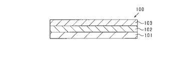
- FIG. 2 is a diagram showing a schematic configuration of the retardation plate.
- FIG. 3 is a diagram showing a schematic configuration of the polarizing plate.
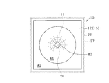
- FIG. 4 is a plan view showing a schematic configuration of the array antenna.
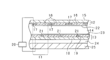
- FIG. 5 is a sectional view showing a schematic configuration of a part of the array antenna.
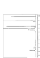
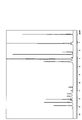
- FIG. 6 is a 1 H-NMR spectrum of the polymer (PI-1).
- FIG. 7 is a 1 H-NMR spectrum of the polymer (PI-2).
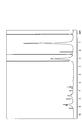
- FIG. 8 is a 1 H-NMR spectrum of the polymer (PI-4).
- FIG. 9 is a 1 H-NMR spectrum of the acidic polymer (PI-1A).
- the composition is a composition exhibiting lyotropic liquid crystallinity (hereinafter, also referred to as “lyotropic liquid crystalline composition”).
- the lyotropic liquid crystalline composition contains a polymer (P) having an acidic functional group, water, and at least one compound (A) selected from the group consisting of a basic monomer and a base generator. Further, in one embodiment of the present disclosure, the composition contains a polymer having a partial structure represented by the following formula (0), water, and the compound (A).
- lyotropic liquid crystalline composition contains a polymer having a partial structure represented by the following formula (0), water, and the compound (A).
- hydrocarbon group means to include a chain hydrocarbon group, an alicyclic hydrocarbon group and an aromatic hydrocarbon group.
- chain hydrocarbon group means a straight chain hydrocarbon group or a branched chain hydrocarbon group which does not include a cyclic structure in the main chain and is composed of only a chain structure. However, it may be saturated or unsaturated.
- alicyclic hydrocarbon group means a hydrocarbon group containing only an alicyclic hydrocarbon structure as a ring structure and not containing an aromatic ring structure. However, it does not need to be composed only of the structure of an alicyclic hydrocarbon, and a part thereof having a chain structure is also included.
- aromatic hydrocarbon group means a hydrocarbon group containing an aromatic ring structure as a ring structure.
- the structure need not be composed of only the aromatic ring structure, and a part thereof may contain a chain structure or an alicyclic hydrocarbon structure.
- organic group means a group containing a hydrocarbon group, and may have a hetero atom in its structure.
- the acidic functional group contained in the polymer (P) is a functional group that forms ions in water.
- a sulfonic acid group, a phosphonic acid group, a carboxylic acid group, or a salt thereof neutralized is preferable because the solubility of the polymer (P) in a solvent containing water can be further increased.
- a sulfonic acid group or a salt thereof is particularly preferable.
- examples of the counter ion include Li + , Na + , K + , Rb + , Cs + , Cu + , Ag + , ammonium ion, pyridinium ion, imidazolium ion, guanidinium ion, Examples include phosphonium ions.
- the counter ion when the counter ion is an inorganic ion, it may be complexed with an organic ligand, and when the counter ion is an organic ion, it may be modified with an organic group.
- the acidic functional group is a carboxylic acid group
- the acid dissociation constant of the carboxylic acid is low, and it is difficult for protons to dissociate under acidic conditions and the ionicity decreases, so it is preferable to form a salt with a strong base.
- the amount of the acidic functional group contained in the polymer (P) is determined from the viewpoint of improving the optical and electrical properties of the organic film exhibiting optical anisotropy, specifically, the solubility and lyotropic property in the polymer (P). From the viewpoint of sufficiently imparting liquid crystallinity, the amount is preferably 50 parts by mole or more, more preferably 100 parts by mole or more, based on 100 parts by mole of the repeating unit constituting the polymer (P).
- the upper limit of the acidic functional group is not particularly limited and can be set arbitrarily.
- the content of the acidic functional group is preferably 300 parts by mol or less, more preferably 200 parts by mol or less, relative to 100 parts by mol of the repeating unit constituting the polymer (P).
- the acidic functional group contained in the polymer (P) may be one type or two or more types.
- the polymer (P) a water-soluble polymer that has liquid crystallinity and can self-assemble can be used.
- the polymer (P) preferably exhibits lyotropic liquid crystallinity in a solvent containing water.
- the main chain of the polymer (P) is not particularly limited, and examples thereof include polyimide, polyamic acid, polyamic acid ester, polyamide, polyimide amide, polyxylylene, polyparaphenylene, polyparaphenylene vinylene, polypeptide, and cellulose. Of these, the polymer (P) is preferably polyimide because of its excellent alignment regulating force with respect to liquid crystals.
- the polymer (P) is a polymer having a partial structure represented by the following formula (0) (hereinafter, referred to as “polymer (PI)” in that it exhibits lyotropic liquid crystallinity under mild conditions of temperature, solvent and concentration. It is also preferable.), and a polymer having a partial structure represented by the following formula (1) is particularly preferable.
- the acidic functional group of the polymer (PI) dissolves in water, and the excluded volume effect derived from the rigid rod-like skeleton and the electrostatic repulsion derived from the acidic functional group are generated.
- a 1 is the following formula (ar-1) or formula (ar-2) Wherein at least one of R 1 to R 10 and R 43 to R 46 is a monovalent group having an acidic functional group, and the rest are each independently a hydrogen atom or a halogen. It is an atom or a monovalent organic group.
- k is 0 or 1. However, it has at least one acidic functional group in the formula (0).
- R 1 to R 10 is a monovalent group having an acidic functional group, and the rest are each independently a hydrogen atom, a halogen atom or a monovalent organic group.
- k is 0 or 1, provided that at least one acidic functional group is contained in the formula (1).
- the monovalent organic group is preferably a hydrocarbon group, more preferably an alkyl group having 1 to 5 carbon atoms. It is a base.
- the monovalent group having an acidic functional group is "*-L 1 -X 1 "(wherein L 1 is a single bond or a divalent linking group, and X 1 is an acidic functional group. "*" is It represents a bond that bonds to the benzene ring).
- L 1 is a divalent linking group
- specific examples of L 1 include an alkanediyl group having 1 to 5 carbon atoms and a group containing —O— between carbon-carbon bonds of the alkanediyl group.
- L 1 is preferably a single bond or an alkanediyl group having 1 to 3 carbon atoms, and more preferably a single bond.
- the number of acidic functional groups respectively contained in the partial structure represented by the above formula (0) and the partial structure represented by the above formula (1) is preferably 1 to 4, and more preferably 1 or 2 Is.
- the partial structure represented by the above formula (0) and the partial structure represented by the above formula (1) are derived from diamines in that they exhibit good lyotropic liquid crystallinity and the degree of freedom of material selectivity is high. It is preferable that the partial structure (that is, at least part of R 3 to R 10 ) has an acidic functional group.
- k is 0 in that liquid crystallinity is exhibited at a lower polymer concentration. Is preferred.
- Specific preferred examples of the partial structure represented by the above formula (0) include partial structures represented by the following formulas (A-1) to (A-8).
- Preferred specific examples of the partial structure represented by the above formula (1) include partial structures represented by the following formulas (A-1) to (A-4).
- M is a cation. A plurality of Ms in the formula are the same or different groups from each other.
- M the illustration of the counter ion when the acidic functional group is a salt is applied.
- M is preferably a monovalent cation, of these, an ammonium ion is preferable, and a tertiary ammonium ion is more preferable.
- the polymer (PI) preferably has at least one selected from the group consisting of the partial structures represented by the formulas (A-1) to (A-6).
- the content of the partial structure represented by the above formula (0) is preferably 50 mol% or more, and 75 mol% based on the total amount of repeating units contained in the polymer (P). % Or more, and more preferably 90 mol% or more.
- the repeating unit contained in the polymer (P) is particularly preferably only the partial structure represented by the above formula (0).
- the repeating unit is a basic unit of the chemical structure of the polymer (P).
- the repeating unit of the polymer (PI) has a structure formed by the reaction of one tetracarboxylic acid derivative and one diamine.
- the polymer (P) can be synthesized according to a standard method of organic chemistry depending on its main chain.
- the polymer (PI) will be described.
- the polymer (PI) is obtained by polymerizing at least one tetracarboxylic acid derivative selected from the group consisting of tetracarboxylic acid dianhydride, tetracarboxylic acid diester and tetracarboxylic acid diester dihalide, and diamine as a raw material composition. It can be obtained by imidizing the obtained polyimide precursor.
- tetracarboxylic acid diester as used herein means a compound in which two of the four carboxyl groups of tetracarboxylic acid are esterified and the remaining two are carboxyl groups.
- tetracarboxylic acid diester dihalide means a compound in which two of the four carboxyl groups of tetracarboxylic acid are esterified and the remaining two are halogenated.
- polyimide precursor includes polyamic acid and polyamic acid ester.
- the tetracarboxylic dianhydride is at least selected from the group consisting of a compound represented by the following formula (t-1) and a compound represented by the following formula (t-2). It is preferable to use one kind of compound (hereinafter, also referred to as “specific acid dianhydride”), and it is more preferable to use a compound represented by the following formula (t-1).
- R 1 and R 2 are each independently a hydrogen atom, a halogen atom, an acidic functional group or a monovalent organic group.
- R 43 to R 46 Are each independently a hydrogen atom, a halogen atom, an acidic functional group or a monovalent organic group.
- the monovalent organic group is a hydrocarbon group having 1 to 20 carbon atoms, Examples thereof include a group in which a hydrogen atom of a hydrocarbon group is replaced with an acidic functional group.
- R 1 , R 2 , and R 43 to R 46 are preferably hydrogen atoms, halogen atoms, methyl groups or trifluoromethyl groups, and more preferably hydrogen atoms.
- the specific acid dianhydrides may be used alone or in combination of two or more.
- a tetracarboxylic acid diester used in the synthesis of the polymer (PI) As a preferred specific example of the tetracarboxylic acid diester used in the synthesis of the polymer (PI), a tetracarboxylic acid dianhydride represented by the above formula (t-1) or the above formula (t-2) is replaced with methanol or Examples thereof include compounds obtained by ring-opening using alcohols such as ethanol.
- Specific preferred examples of the tetracarboxylic acid diester dihalide used in the synthesis of the polymer (PI) include compounds obtained by reacting the tetracarboxylic acid diester with a chlorinating agent such as thionyl chloride.
- the tetracarboxylic acid diester and the tetracarboxylic acid diester dihalide may be used alone or in combination of two or more.
- a diamine having an acidic functional group hereinafter, also referred to as “specific diamine”
- an aromatic diamine having an acidic functional group hereinafter, also referred to as “specific diamine”
- Preferred specific examples of the specific diamine include compounds represented by the following formulas (d-1) to (d-9).
- a specific diamine can be used individually by 1 type or in combination of 2 or more types.
- the polyamic acid (hereinafter, also referred to as “polyamic acid (P)”) that is a precursor of the polymer (PI) can be obtained by reacting tetracarboxylic dianhydride and diamine, for example. Specifically, a method of directly reacting [i] a tetracarboxylic dianhydride and a diamine; [ii] a tetracarboxylic dianhydride or a diamine is neutralized with a base, and then a tetracarboxylic dianhydride and a diamine are neutralized. And a method of reacting with.
- a tetracarboxylic dianhydride other than the specific acid dianhydride hereinafter, also referred to as “other acid dianhydride”
- a diamine other than the specific diamine hereinafter, “other diamine”. It is also possible to use together.
- other acid dianhydrides include aliphatic tetracarboxylic acid dianhydrides, alicyclic tetracarboxylic acid dianhydrides, and aromatic tetracarboxylic acid dianhydrides.
- aliphatic tetracarboxylic acid dianhydrides such as butanetetracarboxylic acid dianhydride and ethylenediaminetetraacetic acid dianhydride
- alicyclic tetracarboxylic acid dianhydrides such as 1,2.
- other acid dianhydride can be used individually by 1 type or in combination of 2 or more types.
- Examples of other diamines include aliphatic diamines, alicyclic diamines, aromatic diamines, and diaminoorganosiloxanes. Specific examples thereof include aliphatic diamines such as metaxylylenediamine and hexamethylenediamine; and alicyclic diamines such as 1,4-diaminocyclohexane and 4,4′-methylenebis(cyclohexylamine).
- An aromatic diamine such as p-phenylenediamine, 2,4-diaminobenzenesulfonic acid, 3,5-diaminobenzoic acid, 4,4′-diaminostilbene-2,2′-disulfonic acid, 2,2′-
- diaminoorganosiloxane examples include dimethyl-4,4′-diaminobiphenyl and the like; for example, 1,3-bis(3-aminopropyl)-tetramethyldisiloxane; and the like.
- the diamine described in 97188 can be used.
- the ratio of the specific acid dianhydride used is lyotropic to the polyamic acid (P).
- the amount is preferably 50 mol% or more, and more preferably 75 mol% or more, based on the total amount of the tetracarboxylic dianhydride used in the synthesis of the polyamic acid (P). More preferably, it is particularly preferably 90 mol% or more.
- the upper limit of the use ratio is not particularly limited and can be arbitrarily set within the range of 100 mol% or less.
- the ratio of the specific diamine used is, with respect to the polyamic acid (P), from the viewpoint of sufficiently imparting solubility in an aqueous solvent and lyotropic liquid crystallinity, to the total amount of the diamine used for the synthesis of the polyamic acid (P), It is preferably 50 mol% or more, more preferably 75 mol% or more, further preferably 90 mol% or more, and particularly preferably 100 mol%.
- the polyamic acid (P) can be obtained by reacting the above-mentioned tetracarboxylic dianhydride and diamine together with a molecular weight modifier, if necessary.
- the ratio of the tetracarboxylic dianhydride and the diamine used for the synthesis reaction of the polyamic acid (P) is such that the acid anhydride group of the tetracarboxylic dianhydride is 0.
- a ratio of 5 to 2 equivalents is preferable, and a ratio of 0.8 to 1.2 equivalents is more preferable.
- various bases can be used, but in an organic solvent.
- an organic base is preferable, a tertiary amine is more preferable, and triethylamine is particularly preferable.
- the ratio of the base used is preferably 0.5 to 5 equivalents, more preferably 1 to 2 equivalents, relative to the acidic functional group.
- the molecular weight modifier examples include acid monoanhydrides such as maleic anhydride, phthalic anhydride and itaconic anhydride, monoamine compounds such as aniline, cyclohexylamine and n-butylamine, monoisocyanate compounds such as phenyl isocyanate and naphthyl isocyanate. Can be mentioned.
- the proportion of the molecular weight modifier used is preferably 20 parts by mass or less, and more preferably 10 parts by mass or less, based on 100 parts by mass of the total tetracarboxylic dianhydride and diamine used.
- the synthesis reaction of the polyamic acid (P) is preferably carried out in an organic solvent.
- the reaction temperature at this time is preferably ⁇ 20° C. to 150° C., more preferably 0 to 100° C.
- the reaction time is preferably 0.1 to 24 hours, more preferably 0.5 to 12 hours.
- Examples of the organic solvent used in the reaction include aprotic polar solvents, phenolic solvents, alcohols, ketones, esters, ethers, halogenated hydrocarbons and hydrocarbons.
- aprotic polar solvents phenolic solvents, alcohols, ketones, esters, ethers, halogenated hydrocarbons and hydrocarbons.
- organic solvents one or more selected from the group consisting of an aprotic polar solvent and a phenolic solvent (first group of organic solvents), or one or more selected from the first group of organic solvents.
- a mixture of at least one selected from the group consisting of alcohols, ketones, esters, ethers, halogenated hydrocarbons and hydrocarbons organic solvent of the second group.
- the use ratio of the second group organic solvent is preferably 50 mass% or less, and more preferably 40 mass% with respect to the total amount of the first group organic solvent and the second group organic solvent. It is below, and more preferably 30% by mass or less.
- organic solvents are N-methyl-2-pyrrolidone, N,N-dimethylacetamide, N,N-dimethylformamide, dimethylsulfoxide, ⁇ -butyrolactone, tetramethylurea, hexamethylphosphortriamide, m-cresol, xylenol. It is preferable to use one or more selected from the group consisting of and halogenated phenols as a solvent, or to use a mixture of one or more of these with other organic solvents in the range of the above ratio.
- the amount (a) of the organic solvent used is preferably such that the total amount (b) of the tetracarboxylic dianhydride and the diamine becomes 1 to 50% by mass with respect to the total amount (a+b) of the reaction solution. ..
- the reaction solution containing the polyamic acid (P) may be subjected to the dehydration ring closure reaction as it is, or may be subjected to the dehydration ring closure reaction after isolating the polyamic acid (P).
- polyamic acid ester The polyamic acid ester (hereinafter, also referred to as “polyamic acid ester (P)” that is a polymer (PI) precursor is, for example, [I] a polyamic acid (P) obtained by the above polymerization reaction and an esterifying agent. Can be obtained by a method of reacting with, a method of reacting [II] tetracarboxylic acid diester with diamine, a method of reacting [III] tetracarboxylic acid diester dihalide with diamine, and the like.
- the polymer (PI) can be obtained by subjecting the polyimide precursor synthesized as described above to dehydration ring closure and imidization.
- the polymer (PI) may be a complete imidized product obtained by dehydrating and ring-closing all of the amic acid structure or amic acid ester structure of the polyimide precursor that is the precursor, and the amic acid structure and amic acid ester may be used.
- a partial imidized product in which only a part of the structure is dehydrated and ring-closed to have an amic acid structure or an amic acid ester structure and an imide ring structure may be used.
- the polymer (PI) preferably has an imidization ratio of 50% or more, and preferably 75% or more, from the viewpoint of obtaining an organic film having a sufficiently high alignment control force and voltage holding ratio in the application of liquid crystal elements. Is more preferable, 90% or more is further preferable, and 95% or more is particularly preferable.
- the imidization ratio is a percentage of the ratio of the number of imide ring structures to the total number of amic acid structures and amic acid ester structures of polyimide and the number of imide ring structures.
- Dehydration ring closure of the polyimide precursor preferably by a method of heating a polyamic acid, or dissolve the polyamic acid in an organic solvent, if necessary by adding at least one of a dehydrating agent and dehydration ring-closing catalyst in this solution. It is carried out by a heating method.
- an acid anhydride such as acetic anhydride, propionic anhydride, trifluoroacetic anhydride can be used as the dehydrating agent.
- the amount of the dehydrating agent used is preferably 0.01 to 20 mol per mol of the amic acid structure of the polyamic acid.
- a base catalyst such as pyridine, triethylamine, 1-methylpiperidine, or an acid catalyst such as methanesulfonic acid or benzoic acid can be used.
- the amount of the dehydration ring-closing catalyst used is preferably 0.01 to 10 mol per 1 mol of the dehydrating agent used.
- the organic solvent used for the dehydration ring closure reaction include the organic solvents exemplified as those used for the synthesis of the polyamic acid (P).
- the reaction temperature for the dehydration ring closure reaction is preferably 0 to 200° C., and the reaction time is preferably 1.0 to 120 hours.
- the reaction solution containing the polymer may be directly used for the preparation of the composition, or the polymer may be isolated and then used for the preparation of the composition.
- the polymer (P) preferably has a solution viscosity of 10 to 2000 mPa ⁇ s, and a solution viscosity of 20 to 1000 mPa ⁇ s when the polymer (P) is made into a solution having a concentration of 10% by mass. It is more preferable to have one.
- the solution viscosity (mPa ⁇ s) of the polymer is 25 using an E-type rotational viscometer for a polymer solution having a concentration of 10 mass% prepared by using a good solvent (for example, water) for the polymer. It is a value measured at °C.
- the polystyrene equivalent weight average molecular weight (M w ) of the polymer (P) measured by gel permeation chromatography (GPC) is preferably 1,000 or more, more preferably 2,000 or more. Further, M w is preferably 500,000 or less, more preferably 100,000 or less.
- the molecular weight distribution ( Mw / Mn ) represented by the ratio of Mw and the polystyrene-equivalent number average molecular weight ( Mn ) measured by GPC is preferably 10 or less, and more preferably 5 or less. .. By having such a molecular weight range, it is possible to easily secure a concentration range and a temperature range in which the composition exhibits lyotropic liquid crystallinity.
- the polymer (P) preferably exhibits lyotropic liquid crystallinity at at least a part of the temperature in the range from 0°C to less than 100°C.
- the temperature range in which the polymer (P) exhibits lyotropic liquid crystallinity is preferably a temperature range including 20 to 40° C., more preferably a temperature range including 20 to 60° C., in a range of 0° C. or higher and lower than 100° C. And more preferably in a temperature range including 20 to 80° C.
- This composition is a liquid composition in which a water-soluble polymer (P) is dissolved in an aqueous solvent.
- the content ratio of water is It is preferably 40% by mass or more, more preferably 60% by mass or more, and further preferably 80% by mass or more based on the total amount (100% by mass) of the solvent contained in the substance.
- the content ratio of water can be 100% by mass or less based on the total amount of the solvent contained in the composition.
- the basic monomer may be any water-soluble compound having a polymerizable group and a basic functional group, and other structures are not particularly limited.
- the polymerizable group contained in the basic monomer is preferably a radical polymerizable group, and more preferably a group having a carbon-carbon unsaturated bond. Particularly preferred is a (meth)acryloyl group or a vinyl group.
- (meth)acryloyl is meant to include “acryloyl” and "methacryloyl”.
- the basic functional group is a functional group capable of acid-base interaction with the acidic functional group of the polymer (P).
- the basic functional group of the basic monomer and the acidic functional group of the polymer (P) interact with each other to form a polyion complex in the film, thereby improving the mechanical properties and water resistance of the liquid crystal alignment film. Can be made In addition, the electrical characteristics of the liquid crystal element can be improved.
- the basic functional group is preferably a functional group containing a nitrogen atom.
- the basic functional group may be protonated or alkylated in the composition, or may be a counter ion of the acidic functional group contained in the polymer (P).
- the basic functional group is a functional group containing a nitrogen atom
- specific examples thereof include a primary amino group (—NH 2 ), a secondary amino group (—NHR 20 ), and a tertiary amino group (—NR 21 R 22 ), a pyridyl group, an imidazoyl group, a guanidino group and the like.
- R 20 , R 21 and R 22 are each independently a monovalent hydrocarbon group having 1 to 10 carbon atoms.
- R 20 , R 21 and R 22 are preferably alkyl groups having 1 to 5 carbon atoms.
- the basic functional group is preferably a group having an acyclic structure from the viewpoint that the polymer (P) can be more excellent in liquid crystal alignment, and can improve the storage stability of the composition. From the viewpoint, a tertiary amino group is more preferable.
- the number of basic functional groups in the basic monomer may be one or plural.
- the number of basic functional groups in one molecule of the basic monomer is preferably 1 from the viewpoint that an ionic crosslink can be appropriately formed in the film to obtain a liquid crystal element exhibiting excellent liquid crystal alignment and electrical characteristics.
- it is two, and more preferably one.
- you may use together a monofunctional basic monomer and a polyfunctional basic monomer.
- At least one selected from the group consisting of (meth)acryloyl group-containing compounds and vinyl group-containing compounds can be preferably used.
- a (meth)acryloyl group-containing compound is more preferable, and a compound represented by the following formula (5) can be particularly preferably used.
- R 30 is a hydrogen atom or a methyl group
- X 2 is —NH— or —O—
- R 31 is a divalent alkanediyl group having 2 to 10 carbon atoms
- R 32 and R 33 are each independently a hydrogen atom or an alkyl group having 1 to 5 carbon atoms, or R 32 and R 33 are combined with each other and are formed together with a nitrogen atom to which R 32 and R 33 are bonded. Represents a ring structure.
- R 31 is preferably linear.
- the carbon number of R 31 is preferably 2-8, more preferably 2-5.
- Examples of the ring structure formed by combining R 32 and R 33 with each other include a pyrrolidine ring, a piperidine ring, and a morpholine ring.
- the basic monomer examples include compounds represented by the following formulas (4-1) to (4-6).
- the basic monomer one kind may be used alone, or two or more kinds may be used in combination.
- the mixing ratio of the basic monomer is preferably 0 based on the total amount of the acidic functional groups contained in the polymer (P), from the viewpoint of sufficiently obtaining the effect of improving the liquid crystal alignment and the electrical properties of the liquid crystal element. 0.2 molar equivalents or more, more preferably 0.5 molar equivalents or more, and further preferably 0.8 molar equivalents or more. Further, the mixing ratio of the basic monomer is preferably 2.0 molar equivalents or less with respect to the total amount of the acidic functional groups contained in the polymer (P), from the viewpoint of suppressing performance deterioration due to generation of an excessive basic polymer. Yes, it is more preferably 1.5 molar equivalents or less, and further preferably 1.0 molar equivalents or less.
- the base generator is a compound that generates a base when at least one of heat and light is applied.
- a thermal base generator can be preferably used from the viewpoint of easy availability, for example, a polyfunctional compound having a plurality of basic functional groups which may be protected (hereinafter, referred to as “polyfunctional base”). Also referred to as ), ionic bases and the like.
- the basic functional group of the polyfunctional base is a functional group capable of acid-base interaction with the acidic functional group of the polymer (P).
- the polyfunctional base is preferably a compound having a nitrogen atom, more preferably a compound represented by the following formula (2).
- R 16 is a (m+n)-valent organic group
- R 17 is a protective group
- R 18 is a hydrogen atom or a monovalent organic group
- X 1 is a base containing a nitrogen atom. Is a monovalent group having a functional group, provided that R 18 and X 1 are combined with each other to form a ring structure with the atom to which they are bonded
- m is 0 or 1
- n is It is an integer of 1 or more and satisfies m+n ⁇ 2.
- examples of R 17 include carbamate-based protecting groups, amide-based protecting groups, imide-based protecting groups, sulfonamide-based protecting groups, and the like.
- a carbamate-based protecting group is preferable, and specific examples thereof include, for example, a tert-butoxycarbonyl group, a benzyloxycarbonyl group, a 1,1-dimethyl-2-haloethyloxycarbonyl group, and a 1,1-dimethyl group.
- examples thereof include a 2-cyanoethyloxycarbonyl group, a 9-fluorenylmethylcarbonyl group and a 2-(trimethylsilyl)ethoxycarbonyl group.
- a tert-butoxycarbonyl group is preferable because it can be easily deprotected by heat and a compound derived from the group eliminated by heating during film formation can be discharged as a gas outside the film.
- Examples of the monovalent organic group for R 18 include a monovalent hydrocarbon group having 1 to 10 carbon atoms and a protecting group.
- R 18 is preferably a hydrogen atom, an alkyl group having 1 to 3 carbon atoms or a tert-butoxycarbonyl group.
- R 16 is, for example, a divalent hydrocarbon group having 1 to 20 carbon atoms, a group having —O— between carbon-carbon bonds of a hydrocarbon group having 2 to 20 carbon atoms, or a divalent hydrocarbon group having 1 to 20 carbon atoms.
- a group in which the hydrogen atom of the hydrocarbon group is substituted with a substituent such as —OH or —COOH.
- R 16 is preferably a divalent hydrocarbon group having 1 to 20 carbon atoms, or a group substituted with —OH or —COOH.
- X 1 include an amino group, a pyridyl group, an imidazoyl group and a guanidino group.
- m is preferably 1.
- n is preferably 1 to 4, and more preferably 1 or 2.
- the base generator include polyfunctional bases such as compounds represented by the following formulas (2-1) to (2-6); and ionic bases such as the following formula (3). Examples thereof include compounds represented by -1).
- a polyfunctional base is preferably used from the viewpoint that the effect of improving the mechanical properties and water resistance of the liquid crystal alignment film and the electrical properties of the liquid crystal element is high.
- the mixing ratio of the base generator is based on the total amount of acidic functional groups contained in the polymer (P) contained in the composition, from the viewpoint of sufficiently obtaining the effect of improving the electrical characteristics of the liquid crystal element.
- the ratio of the basic functional group of the base generator is preferably 0.2 molar equivalents or more, more preferably 0.5 molar equivalents or more, and 0.8 molar equivalents or more. Is more preferable.
- the mixing ratio of the base generator is such that the base of the base generator is based on the total amount of acidic functional groups contained in the polymer (P) contained in the composition, from the viewpoint of suppressing performance deterioration due to excessive crosslinking formation.
- the ratio of the functional group is preferably 2.0 molar equivalents or less, more preferably 1.5 molar equivalents or less, and further preferably 1.0 molar equivalents or less. preferable.
- the composition may contain other components other than the polymer (P), water and the compound (A) within a range that does not impair the object and effects of the present disclosure.
- the composition preferably further contains a polymerization initiator.
- a polymerization initiator water-soluble thermal polymerization initiators and photopolymerization initiators can be used. Specific examples thereof include 4,4′-azobis(4-cyanovaleric acid) and 2,2′-azobis[2-(2-imidazolin-2-yl)propane]diene as water-soluble thermal polymerization initiators.
- the mixing ratio of the polymerization initiator is preferably 0.001% by mass or more, and more preferably 0.01% by mass, based on the total amount of the composition, from the viewpoint of sufficiently promoting the polymerization of the basic monomer in the film. That is all. Further, the blending ratio of the polymerization initiator is preferably 1.0% by mass or less, and more preferably 0.1% by mass or less, based on the total amount of the composition.
- the composition may contain a polymer different from the polymer (P) (hereinafter, also referred to as “other polymer”).
- the other polymer for example, a polyamic acid obtained by reacting the other tetracarboxylic dianhydride with the other diamine, an imidized polymer of the polyamic acid, an esterified polymer of the polyamic acid.
- “(meth)acrylate” is meant to include “acrylate” and "methacrylate”.
- its blending ratio is preferably 30 parts by mass or less, more preferably 10 parts by mass or less, and further preferably 10 parts by mass or less with respect to 100 parts by mass in total of the polymers contained in the composition. It is preferably 5 parts by mass or less.
- the composition may contain rod-shaped molecules or rod-shaped nanostructures (hereinafter, also referred to as “rod-shaped molecules and the like”). By applying shear stress to the composition, it is possible to control the orientation of rod-shaped molecules and the like in accordance with the uniaxial orientation of the polymer (P).
- rod-shaped molecules include dichroic dyes
- rod-shaped nanostructures include dye aggregates, quantum rods, metal nanorods, carbon nanotubes, proteins, nucleic acids, viruses and the like.
- Various functionalities can be imparted by controlling the orientation of rod-shaped molecules, and among these, at least one selected from the group consisting of dichroic dyes, dye aggregates, quantum rods, metal nanorods and carbon nanotubes.
- a composition containing a dichroic dye can form a guest-host type polarizing plate.
- the composition containing the quantum rods can form a wavelength conversion plate capable of emitting polarized light, and the composition containing carbon nanotubes can form a wire or an actuator having conductive anisotropy. it can.
- the mixing ratio of the rod-shaped molecule or the like in the composition can be appropriately set depending on the type of the rod-shaped molecule or the like within a range that does not impair the effects of the present disclosure.
- solvent As a solvent component of the present composition, a solvent other than water (hereinafter, also referred to as “other solvent”) may be used.
- the other solvent may be any solvent that can be mixed uniformly with water, and examples thereof include methanol, ethanol, n-propanol, i-propanol, n-butanol, ethylene glycol, acetone, methyl ethyl ketone, tetrahydrofuran, N- Methyl-2-pyrrolidone, ⁇ -butyrolactone, 1-butoxy-2-propanol, diacetone alcohol, dipropylene glycol monomethyl ether, ethyl lactate, ethylene glycol methyl ether, ethylene glycol-n-butyl ether (butyl cellosolve), diethylene glycol monomethyl ether, Examples thereof include diethylene glycol monoethyl ether, diethylene glycol monomethyl ether acetate, diethylene glycol monoethyl ether acetate
- the organic solvent used is preferably an organic solvent having a lower boiling point than that of water, and comprises methanol, ethanol, n-propanol, i-propanol, acetone and tetrahydrofuran. More preferably, it is at least one selected from the group.
- the content ratio of the organic solvent is preferably 50% by mass or less, more preferably 25% by mass or less, based on the total amount of the mixed solvent. It is more preferable to set it to 10% by mass or less.
- other components include, for example, compounds having at least one epoxy group in the molecule, functional silane compounds, surfactants, fillers, pigments, defoamers, sensitizers, dispersants, antioxidants. Agents, adhesion promoters, antistatic agents, leveling agents, antibacterial agents and the like.
- these compounding ratios can be appropriately set within a range that does not impair the effects of the present disclosure, depending on each compound to be compounded.
- the polymer (P) concentration in the composition is preferably a concentration at which the composition exhibits lyotropic liquid crystallinity.
- the concentration of the polymer (P) is preferably 1 to 20 mass% with respect to the total amount of the solvent and the polymer (P).
- the concentration of the polymer (P) is more preferably 1 to 10% by mass, further preferably 1 to 5% by mass, based on the total amount of the solvent and the polymer (P).
- the polymer (PI) is preferable in that a composition exhibiting lyotropic liquid crystallinity can be obtained at a relatively low polymer concentration. Therefore, the coating property when forming a coating film on a substrate is good, a thin film having a film thickness of about 0.05 to 0.5 ⁇ m can be formed, and industrial productivity is excellent.
- the solid content concentration of the composition (the ratio of the total mass of components other than the solvent of the composition to the total mass of the composition) is appropriately selected in consideration of viscosity, volatility, etc., but is preferably 1 to 30. %, more preferably 1 to 20% by mass, particularly preferably 1 to 10% by mass.
- the composition may be applied to the surface of a substrate and preferably dried to form a coating film. At this time, the solid content concentration of 1% by mass or more is preferable because the composition easily exhibits lyotropic liquid crystallinity.
- the temperature for preparing the composition is preferably 10 to 90°C, more preferably 20 to 80°C.
- an organic film having optical anisotropy By using the above composition, an organic film having optical anisotropy can be obtained.
- the organic film is formed by applying the composition in a liquid crystal phase on a base material and drying the composition in a state of being caused to flow by shear stress (application drying step). This makes it possible to obtain a coating film in which the molecular chains of the polymer (P) are uniaxially oriented in a shearing direction in a self-organizing manner.
- the composition is preferably applied by a bar coater method, an applicator method, a die coater method or a blade coater method. These methods are preferable because the molecular chains of the polymer (P) are easily oriented by the flow due to shear stress.
- the heating temperature is preferably around the boiling point of water or higher.
- the specific heating temperature can be appropriately set according to the use of the organic film, the type of the base material, the type of the compound (A) or the polymerization initiator in the composition, and the like.
- the heating temperature is preferably 10 hours or more half-life temperature ⁇ i of the thermal polymerization initiator.
- the heating temperature is more preferably ⁇ i+20° C. or higher, and further preferably ⁇ i+40° C. or higher.
- the coating and drying step it is preferable to control the composition so as not to deviate from the temperature range and the concentration range in which the composition exhibits lyotropic liquid crystallinity.
- the orientation may be relaxed and the anisotropy of the coating film may disappear.
- the composition is heated or exposed to light so that the acidic functional group of the polymer (P) and the basic functional group of the compound (A) interact with each other by acid-base interaction. ,
- the polymer (P) is ionically crosslinked and becomes insoluble. This makes it possible to obtain an organic film having high water resistance and mechanical properties and excellent optical properties and electrical properties.
- a treatment such as immersing the organic film in a polyvalent metal ion aqueous solution (eg, calcium hydroxide aqueous solution) is usually required.
- a polyvalent metal ion aqueous solution eg, calcium hydroxide aqueous solution
- ionic crosslinks can be formed in the film by heating or exposing during film formation. This is preferable in that it is not necessary to provide a step of performing a passivation process after forming the film, and the production process can be simplified.
- the mode of ionic crosslinking by heating or exposure differs depending on the type of compound (A).
- the compound (A) is a basic monomer
- the basic monomer is polymerized by heat or light to become a polycation, and an acid-base interaction with a polyanion derived from the polymer (P) causes a polyion complex in the film. Is formed.
- the composition contains a thermal polymerization initiator
- ionic crosslinking can be formed in the film by heating for forming the film. As a result, it is not necessary to separately provide a step for ionic crosslinking after forming the film, and the production process can be further simplified.
- the compound (A) is a base generator
- a base is generated by heat or light, and an acid-base interaction with the polyanion derived from the polymer (P) forms an ionic crosslink in the film.
- a polyfunctional thermal base generator is contained as the compound (A)
- a polycation is generated by heating during film formation, and an acid-base interaction with a polyanion derived from the polymer (P) causes the polycation in the film. It is possible to form a polyion complex. Therefore, it is not necessary to separately provide a passivation step after forming the film.
- the compound (A) When the compound (A) is a photopolymerizable monomer or a photobase generator, it may be exposed before drying the coating liquid, or may be exposed after forming the organic film by drying the coating liquid. In the latter method, a pattern can be formed on the organic film by exposing through a photomask. That is, the exposed portion of the exposed organic film becomes insoluble in the aqueous solvent due to the formation of ionic crosslinks, while the unexposed portion remains soluble in the aqueous solvent. Accordingly, an organic film having a desired pattern can be obtained by using an aqueous solvent as a developing solution and bringing the exposed organic film into contact with the developing solution.
- the polymer (P) is a rigid rod-shaped polymer and acts as a mesogen in a solvent.
- the polymer (PI) is a rigid and highly uniaxially linear aromatic polyimide having a structure in which a benzene ring and an imide ring are linked or a structure in which a naphthalene ring and an imide ring are linked in the main chain.
- the rod-shaped molecule or the like can be oriented along the molecular chain of the polymer (P). .. Therefore, by using the composition of the present disclosure, a retardation plate, a polarizing plate, a wavelength conversion plate or the like which exhibits good characteristics by utilizing the characteristics of the polymer (P) can be easily and reduced in environmental load. Can be formed while.
- the liquid crystal alignment film of the present disclosure can be formed by using the composition prepared as described above as a liquid crystal aligning agent. Further, the liquid crystal element of the present disclosure includes a liquid crystal alignment film formed using the above composition (liquid crystal aligning agent).
- the composition of the present disclosure can impart liquid crystal aligning ability to a coating film by shear flow. Therefore, according to the above composition, the conventional rubbing treatment or photo-alignment treatment is not required when forming the liquid crystal alignment film, and the process can be simplified. Further, since it is an aqueous solvent, it can be fired at a low temperature, which has an advantage that the environmental load can be reduced.
- its driving mode is not particularly limited, and it can be applied to various driving modes such as TN type, STN type, IPS type, FFS type, VA type, MVA type and PSA type.
- FIG. 1 shows a schematic configuration diagram of a TN type liquid crystal display device 300 as a specific example of the liquid crystal element.
- the liquid crystal display device 300 of FIG. 1 includes a pair of substrates 301 and 302, a pair of electrodes 303 and 304 formed on respective substrate surfaces of the pair of substrates 301 and 302, and a pair of electrodes 303 and 304.
- Liquid crystal alignment films 303 and 304 formed on the surface.
- the pair of substrates 301 and 302 are arranged facing each other with a predetermined cell gap so that the liquid crystal alignment films 303 and 304 face each other.
- a liquid crystal layer 307 is provided between the pair of substrates 301 and 302 adjacent to the liquid crystal alignment films 303 and 304.
- Polarizing plates (not shown) are attached to the outer surfaces of the substrates 301 and 302.
- the orientation of the liquid crystal in the liquid crystal layer 307 is controlled by switching the application/release of the voltage between the pair of substrates 301 and 302.
- the liquid crystal display element can be manufactured by, for example, a method including the following steps (1-1) and (1-2).
- Step (1-1): Application and Drying First, the composition is applied onto a substrate, and then the applied surface is preferably heated to form a coating film on the substrate.
- the substrate for example, a glass such as float glass or soda glass; a transparent substrate made of plastic such as polyethylene terephthalate, polybutylene terephthalate, polyether sulfone, polycarbonate, poly (alicyclic olefin) can be used.
- a NESA film made of tin oxide (SnO 2 ) (registered trademark of PPG Co., USA), an ITO film made of indium oxide-tin oxide (In 2 O 3 —SnO 2 ) and the like are used.
- a TN type, STN type, or VA type liquid crystal element two substrates provided with a patterned transparent conductive film are used.
- an IPS-type or FFS-type liquid crystal element a substrate provided with an electrode formed of a comb-shaped patterned transparent conductive film or a metal film, and a counter substrate provided with no electrode To use.
- the metal film for example, a film made of a metal such as chromium can be used.
- the liquid crystal aligning agent is applied to the substrate on the electrode forming surface, preferably by a bar coater method, an applicator method, a die coater method or a blade coater method.
- the relative speed between the substrate and the coater is preferably 1 to 200 cm/s from the viewpoint of controlling the liquid crystal pretilt angle at the interface of the liquid crystal alignment film in the liquid crystal element. , More preferably 2 to 100 cm/s, and particularly preferably 5 to 50 cm/s.
- the liquid crystal pretilt angle depends on the molecular orientation of the coating film interface and changes depending on various factors such as the coater shape and the drying conditions in addition to the shear rate. Therefore, each factor depends on the liquid crystal aligning agent. It can be set appropriately.
- preheating is preferably performed for the purpose of preventing dripping of the applied composition.
- the prebaking temperature is preferably 30 to 100°C, more preferably 40 to 80°C, and particularly preferably 40 to 60°C.
- the prebaking time is preferably 0.25 to 10 minutes, more preferably 0.5 to 5 minutes.
- a baking (post-baking) step is performed for the purpose of completely removing the solvent.
- the baking temperature (post-baking temperature) at this time is preferably 60 to 300°C, more preferably 100 to 250°C.
- the post-baking time is preferably 5 to 120 minutes, more preferably 10 to 60 minutes.
- the coating film made of the liquid crystal aligning agent applied on the substrate is in a state in which the molecular chains of the polymer (P) are oriented by the flow due to the shear stress and then dried in that state.
- the liquid crystal alignment ability is imparted to the coating film by a simple operation, and the liquid crystal alignment film can be formed.
- the thickness of the film formed is preferably 1 nm to 1 ⁇ m, more preferably 5 nm to 0.5 ⁇ m.
- Step (1-2): Construction of Liquid Crystal Cell In this step, two substrates on which a liquid crystal alignment film is formed are prepared, and a liquid crystal is arranged between the two substrates which are arranged to face each other to manufacture a liquid crystal cell.
- the liquid crystal cell for example, the following two methods can be mentioned.
- the first method first, two substrates are arranged to face each other with a gap (cell gap) so that the liquid crystal alignment films face each other, and the peripheral portions of the two substrates are bonded together by using a sealant.
- a liquid crystal cell is manufactured by injecting and filling a liquid crystal into the cell gap defined by the substrate surface and the sealant, and then sealing the injection hole.
- an ultraviolet light curable sealant is applied to a predetermined place on one of the two substrates on which the liquid crystal alignment film is formed, and the liquid crystal alignment film surface is further applied.
- the other substrate is attached so that the liquid crystal alignment film faces and the liquid crystal is spread over the entire surface of the substrate, and then the entire surface of the substrate is irradiated with ultraviolet light to obtain a sealant.
- a liquid crystal cell is manufactured by curing. In either case, the liquid crystal cell manufactured as described above is further heated to a temperature at which the liquid crystal used has an isotropic phase, and then gradually cooled to room temperature, so that the flow orientation at the time of filling the liquid crystal can be improved. It is desirable to remove it.
- a curing agent and an epoxy resin containing aluminum oxide spheres as a spacer can be used.
- the liquid crystal include nematic liquid crystal and smectic liquid crystal, and among them, nematic liquid crystal is preferable.
- a liquid crystal display element can be obtained by attaching a polarizing plate to the outer surface of the liquid crystal cell.
- the polarizing plate include a polarizing plate in which a polarizing film called "H film" in which polyvinyl alcohol is stretched and oriented to absorb iodine is sandwiched between cellulose acetate protective films, or a polarizing plate composed of the H film itself. ..
- the liquid crystal device of the present disclosure can be effectively applied to various applications, and for example, a watch, a portable game, a word processor, a notebook computer, a car navigation system, a camcorder, a PDA, a digital camera, a mobile phone, a smartphone, various monitors, a liquid crystal television, It can be applied to various liquid crystal display devices such as information displays and light control films.
- the retardation plate of the present disclosure can be manufactured using the above composition.
- a specific example of the retardation plate is the retardation plate 100 shown in FIG.
- the retardation plate 100 has a base material 101, a liquid crystal alignment film 102, and a liquid crystal layer 103, which are laminated in this order.
- the retardation plate 100 can be manufactured by, for example, a method including the following step (2-1) and step (2-2).
- Step (2-1): Application and Drying In order to manufacture the retardation plate of the present disclosure, first, the above composition is preferably applied to a substrate 101 (for example, a glass substrate, triacetyl cellulose (by a bar coater method, an applicator method, a die coater method or a blade coater method). TAC), polyethylene terephthalate, polymethylmethacrylate, etc.). Then, the coating liquid on the base material 101 is dried in a state where the molecular chains of the polymer (P) are oriented by the flow due to shear stress.
- a substrate 101 for example, a glass substrate, triacetyl cellulose (by a bar coater method, an applicator method, a die coater method or a blade coater method). TAC), polyethylene terephthalate, polymethylmethacrylate, etc.
- the coating liquid on the base material 101 is dried in a state where the molecular chains of the polymer (P) are oriented by the flow due to shear stress
- the drying process is preferably performed by heating (baking) the coated surface.
- preheating prebaking
- postbaking may be performed for the purpose of preventing liquid dripping
- postbaking may be performed.
- the heating temperature is preferably 40 to 150°C, more preferably 80 to 140°C.
- the heating time is preferably 0.1 to 120 minutes, more preferably 1 to 60 minutes.
- the thickness of the coating film (liquid crystal alignment film 102) formed on the substrate is preferably 1 nm to 1 ⁇ m, more preferably 5 nm to 0.5 ⁇ m.
- Step (2-2): Formation of Liquid Crystal Layer Then, a polymerizable liquid crystal is applied and cured on the liquid crystal alignment film 102 formed as described above. As a result, a layer containing the polymerizable liquid crystal (liquid crystal layer 103) is formed.
- the polymerizable liquid crystal used here is a liquid crystal compound or a liquid crystal composition that is polymerized by at least one treatment of heating and light irradiation.
- a conventionally known one used for forming a liquid crystal layer of a retardation plate can be used, for example, it is described in "Liquid Crystal Handbook" (Edited by Liquid Crystal Handbook Editorial Committee).
- the nematic liquid crystal which has a polymeric group can be mentioned among the said liquid crystals.
- a mixture of a plurality of liquid crystal compounds may be used as the polymerizable liquid crystal, or a composition containing a known polymerization initiator, a suitable solvent and the like may be used.
- an appropriate application method such as a bar coater method, a roll coater method, a spinner method, a printing method, or an inkjet method can be adopted.
- the polymerizable liquid crystal applied on the liquid crystal alignment film 102 is subjected to one or more treatments selected from heating and light irradiation to cure the coating film to form the liquid crystal layer 103. It is preferable to perform these treatments in a superimposed manner because good orientation can be obtained.
- the heating temperature at this time is appropriately selected depending on the type of the polymerizable liquid crystal used. For example, when using RMS03-013C manufactured by Merck, it is preferable to heat at a temperature in the range of 40 to 80°C. The heating time is preferably 0.5 to 5 minutes.
- the irradiation light non-polarized ultraviolet rays having a wavelength in the range of 200 to 500 nm can be preferably used.
- the irradiation amount of light is preferably 50 to 10,000 mJ/cm 2 , and more preferably 100 to 5,000 mJ/cm 2 .
- the thickness of the liquid crystal layer 103 to be formed is appropriately set according to desired optical characteristics. For example, when manufacturing a half-wave plate for visible light with a wavelength of 540 nm, a thickness is selected such that the retardation film formed has a retardation of 240 to 300 nm. The thickness is selected so that the phase difference is 120 to 150 nm. The thickness of the liquid crystal layer 103 that achieves the target retardation varies depending on the optical characteristics of the polymerizable liquid crystal used. For example, when using RMS03-013C manufactured by Merck, the thickness for manufacturing the quarter-wave plate is in the range of 0.6 to 1.5 ⁇ m.
- the retardation plate obtained by the above method is suitable as a retardation plate for a liquid crystal display device.
- the operation mode of the applied liquid crystal display element is not limited, and it can be applied to various known modes such as TN type, STN type, IPS type, FFS type and VA type.
- the retardation plate 100 is used by attaching the surface of the retardation plate on the base material side to the outer surface of the polarizing plate arranged on the viewing side of the liquid crystal display element. Therefore, it is preferable that the base material of the retardation plate is made of TAC or an acrylic base material, and the base material of the retardation plate also functions as a protective film of the polarizing film.
- a roll-to-roll method as a method for producing a retardation plate on an industrial scale.
- a film is unwound from a wound body of a long base film, a liquid crystal alignment film 102 is formed on the unwound film, and a polymerizable liquid crystal is applied onto the liquid crystal alignment film 102.
- This is a method in which the steps of curing and, if necessary, the step of laminating a protective film are performed in continuous steps, and the film after the steps is recovered as a wound body.
- the above composition used for forming the liquid crystal alignment film 102 is preferable in that the process can be simplified because the composition is aligned by the shear stress at the time of application, and the retardation plate 100 can be manufactured at low cost. Further, by forming the liquid crystal alignment film 102 using the above composition, even when the liquid crystal alignment film 102 is coated with a polymerizable liquid crystal, the alignment relaxation of the liquid crystal alignment film 102 is unlikely to occur, and an excellent optical compensation function is obtained. Can be expressed.
- the polarizing plate of the present disclosure can be manufactured using the above composition.
- a specific example of the polarizing plate is the polarizing plate 200 shown in FIG.
- the polarizing plate 200 has a substrate 201 and a polarizing film 202, which are laminated in this order.
- a composition containing a polymer (P), water, a compound (A) and a dichroic dye is added to a substrate (eg, a glass substrate, a trilayer). It is applied onto acetyl cellulose (TAC), polyethylene terephthalate, polymethyl methacrylate, etc., preferably by a bar coater method, an applicator method, a die coater method or a blade coater method.
- TAC acetyl cellulose
- P polyethylene terephthalate
- polymethyl methacrylate e.g., a bar coater method, an applicator method, a die coater method or a blade coater method.
- the molecular chains of the polymer (P) are dried in a state of being oriented by a flow due to shear stress. Thereby, a guest-host type polarizing plate can be obtained.
- a resin film (protective film) may be attached to one surface or both surfaces of the polarizing plate.
- a protective film having an optical function such as a retardation film may be used as the protective film.
- the thickness of the polarizing film formed on the substrate is preferably 0.1 to 50 ⁇ m, more preferably 1 to 10 ⁇ m.
- the dichroic pigment iodine or a dichroic organic dye can be used.
- the dichroic organic dye used is not particularly limited, and known compounds can be appropriately used, and examples thereof include polyiodine, azo compounds, anthraquinone compounds, and dioxazine compounds.
- the dichroic dye one type may be used alone, or two or more types may be combined.
- the compounding ratio of the dichroic dye (when two or more kinds are compounded, the total amount thereof) is preferably 0.05 to 15% by mass, more preferably 0, relative to the total mass in the composition. 0.1 to 10% by mass.
- a composition containing a polymer (P), water, a compound (A) and a metal (metal nanorod, metal nanowire, or metal ion) is used, and a guest-host type
- the composition is applied onto the substrate in the same manner as in the method for producing a polarizing plate.
- the molecular chains of the polymer (P) are dried in a state of being oriented by a flow due to shear stress. Thereby, a reflective polarizing plate can be obtained.
- a metal ion is used as the metal
- a polarizing plate having excellent optical anisotropy can be obtained by performing a treatment for anisotropically depositing a simple metal along the polymer (P) by reduction.
- the polarizing plate thus obtained has good polarization characteristics, and thus can be suitably used as a polarizing plate to be attached to various display devices such as a liquid crystal display device and an organic electroluminescence (EL) display device.
- various display devices such as a liquid crystal display device and an organic electroluminescence (EL) display device.
- EL organic electroluminescence
- the liquid crystal antenna of the present disclosure includes a liquid crystal alignment film manufactured using the above composition. Embodiments of the liquid crystal antenna will be described below with reference to the drawings.
- the liquid crystal antenna 10 is a planar liquid crystal antenna that utilizes the fact that the dielectric constant of a liquid crystal material changes according to the strength of an electric field, and is a phased array antenna having a plurality of antenna units 11.
- the liquid crystal antenna 10 controls the electric field applied to the liquid crystal material to change the dielectric constant of the liquid crystal material of each antenna unit 11, thereby transmitting high frequency energy as electromagnetic waves in any direction of space or in any direction of space. Receive electromagnetic waves.
- the liquid crystal antenna 10 is a radial line slot antenna in which a plurality of antenna units 11 are concentrically arranged in a transmission/reception area A1 that functions as a transmission/reception unit, and can transmit or receive circular polarized waves.
- the liquid crystal antenna 10 includes a patch substrate 12, a slot substrate 13, and a liquid crystal layer 14.
- the wave transmission/reception area A1 is annular
- the non-transmission/reception area A2 is arranged on the outer peripheral side of the wave transmission/reception area A1
- the non-transmission/reception area A3 is arranged on the inner peripheral side of the wave transmission/reception area A1. ..
- the patch substrate 12 includes a dielectric substrate 15 such as a glass substrate or a plastic substrate, a plurality of patch electrodes 16 formed on one surface of the dielectric substrate 15, and a plurality of patch electrodes 16 respectively connected to the plurality of patch electrodes 16.
- the patch electrode 16 is a metal layer made of copper, aluminum, or the like, and has a thickness of, for example, about 1 to 2 ⁇ m.
- the TFT 17 is electrically connected to a gate bus line and a source bus line (not shown), and energization is controlled by the control unit 20.
- Each antenna unit 11 is configured to include one patch electrode 16 and one TFT 17. Each area of the antenna unit 11 is defined by a gate bus line and a source bus line.
- the slot substrate 13 has a dielectric substrate 18 such as a glass substrate or a plastic substrate, and a slot electrode 19 in which a plurality of slots 21 are arranged.
- the slot electrode 19 is a metal layer made of copper, aluminum, or the like, and has a thickness of, for example, about 2 to 20 ⁇ m.
- the energization of the slot electrode 19 is controlled by the control unit 20.
- the plurality of slots 21 are formed by arranging a pair of slots extending in directions intersecting with each other in a concentric circle in the wave transmission/reception area A1.
- a first alignment film 22 is formed on the electrode formation surface of the patch substrate 12, and a second alignment film 23 is formed on the electrode formation surface of the slot substrate 13.
- the first alignment film 22 and the second alignment film 23 are liquid crystal alignment films that control the alignment of liquid crystal molecules. These alignment films 22 and 23 are formed by applying the above composition onto a substrate and drying the polymer (P) in a state where the molecular chains of the polymer (P) are aligned by the flow due to shear stress.
- the patch substrate 12 and the slot substrate 13 are spaced from each other by a sealant disposed in the non-transmission/reception regions A2 and A3 so that their electrode forming surfaces (that is, liquid crystal alignment film forming surfaces) face each other. Are arranged.
- the patch electrode 16 is arranged so as to face the slot 21 (see FIG. 5).
- a liquid crystal layer 14 is provided adjacent to the first alignment film 22 and the second alignment film 23 in a space surrounded by the patch substrate 12, the slot substrate 13 and the sealant.
- the liquid crystal layer 14 is filled with a liquid crystal material.
- a material having a large anisotropy of dielectric constant with respect to a high frequency such as a microwave or a millimeter wave and a small dielectric loss (that is, tan ⁇ ) is preferable.
- a bistran compound for example, a compound represented by the following formula (R-1)
- an oligophenylene compound for example, a compound represented by the following formula (R-2)
- a bistran compound A mixture of a compound and an oligophenylene compound can be used.
- the thickness of the liquid crystal layer 14 is, for example, 5 to 400 ⁇ m.
- R 21 to R 23 are each independently an alkyl group having 1 to 15 carbon atoms, an alkoxy group, an alkenyl group, an alkenyloxy group, an alkoxyalkyl group, a cycloalkyl group, an alkylcyclo group.
- R 24 and R 25 are each independently a hydrogen atom, a halogen atom, an alkyl group having 1 to 15 carbon atoms, a fluorinated alkyl group, an alkoxy group, a fluorinated alkoxy group or an alkenyl group.
- R 26 is a fluorine atom, a chlorine atom, or an alkyl group having 1 to 15 carbon atoms, k is an integer of 0 to 4, and m is an integer of 6 to 25.
- liquid crystal material examples include bistran compounds such as compounds represented by the following formulas (r-1-1) to (r-1-4); and oligophenylene compounds such as the following. Examples thereof include compounds represented by formula (r-2-1) and formula (r-2-2).
- the liquid crystal material one kind may be used alone, or two or more kinds may be used in combination.
- a ground plate 25 is arranged on the opposite side of the slot substrate 13 from the electrode formation surface via a low dielectric layer 24.
- the ground plate 25 is formed of an aluminum plate or a copper plate and has a thickness of about several mm.
- the low dielectric layer 24 is a layer having a low dielectric constant with respect to high frequencies, and is an air layer in this embodiment. Instead of the air layer, a resin layer made of a fluorine resin such as PTFE may be arranged as the low dielectric layer 24.
- a power supply pin 26 is attached to the non-transmission/reception area A3 on the opposite side of the slot substrate 13 from the electrode formation surface.
- the power supply pin 26 penetrates the ground plate 25 and is connected to a signal line (not shown).
- a plurality of antenna units 11 are arranged side by side in the wave transmission/reception area A1 in a concentric pattern centered on the power feed pin 26.
- the liquid crystal antenna 10 receives electromagnetic waves in the space from the patch substrate 12 side or radiates the electromagnetic waves to the space, and the slot electrode 19, the dielectric substrate 18, the low dielectric layer 24, and the ground plate 25 function as a waveguide. Transmits high frequency energy.
- the internal unit 28 including the patch substrate 12, the slot substrate 13, and the liquid crystal layer 14 is housed in a resin housing 27 (see FIG. 4).
- the housing 27 is a resin container formed by using at least one selected from the group consisting of an epoxy resin, a polyimide resin, a liquid crystal polymer, and a fluorine resin, in that the dielectric loss of the liquid crystal antenna 10 can be further reduced.
- it is formed using a fluororesin (PTFE or the like).
- the size of the liquid crystal antenna 10 is appropriately set according to the amount of communication and the like, but is, for example, 20 cm to 3 m.
- the liquid crystal antenna 10 obtained by using the above composition has a high liquid crystal alignment film strength, excellent water resistance, and a small dielectric loss. Therefore, this liquid crystal antenna is preferably used for transmission, reception or transmission/reception of high frequencies such as microwaves and millimeter waves.
- the use is not particularly limited, but for example, an antenna mounted on a moving body such as an automobile, a railroad vehicle, an aircraft, a ship, a robot, specifically, an information communication antenna, a broadcasting antenna, a telephone antenna, and a GPS antenna. It can be applied to an antenna or the like.
- patterned liquid crystal alignment film ⁇ Method for producing patterned liquid crystal alignment film>>
- the composition contains a photopolymerization initiator or a photobase generator as a photosensitive compound
- a pattern is formed on the liquid crystal alignment film by irradiating the liquid crystal alignment film formed using the composition with radiation.
- the patterned liquid crystal alignment film of the present disclosure can be produced by a method including the following step (3-1), step (3-2) and step (3-3).
- Step (3-1) Coating and drying step
- a composition containing a photopolymerizable monomer or a photobase generator as the compound (A) is applied onto a substrate in a liquid crystal phase state, and the molecular chains of the polymer (P) are oriented by flow due to shear stress. Let it dry. As a result, a photosensitive liquid crystal alignment film is formed on the substrate.
- the description of the above step (1-1) is applied to each condition of coating and drying in this step.
- Step (3-2): Exposure Step In the subsequent main step, the liquid crystal alignment film formed in the step (3-1) is irradiated with radiation through a mask having a predetermined pattern.
- a polyion complex is formed in the exposed portion of the film to make it insoluble in an aqueous solvent, while the unexposed portion maintains water solubility.
- the exposure conditions such as the exposure amount and the exposure time can be appropriately selected according to the composition of the composition, the type of additives, and the like.
- Step (3-3) Development Step
- a liquid crystal alignment film having a desired pattern patterned liquid crystal alignment film
- the developing solution used in the developing step other than water, other solvent that may be added to the composition or a mixed solvent of water and other solvent may be used.
- the developing conditions such as the amount of the developing solution used and the developing time can be appropriately selected according to the compounding composition of the lyotropic liquid crystalline composition, the kind of the additive and the like.
- the patterned liquid crystal alignment film thus obtained can be used for various optical applications.
- the outer edge portion to which the sealing material is applied is unexposed, and the area other than the outer edge portion is exposed and developed to remove the liquid crystal alignment film on the outer edge portion.
- the substrate and the sealing material can be brought into direct contact with each other, and the adhesion between the substrate and the sealing material can be improved.
- a liquid crystal alignment film used for optical applications such as holography can be formed.
- Base monomer M-1; N,N-dimethylaminopropyl acrylamide (polymerization initiator) I-1; azobis[2-(-imidazolin-2-yl)propane] disulfate dihydrate I-2; 2-hydroxy-4'-(2-hydroxyethoxy)-2-methylpropiophenone ( Thermal base generator) A-1; N- ⁇ -(tert-butoxycarbonyl)-L-arginine A-2; Triethylenediamine oxalate
- Imidization rate [%] (1-A NH 2 /A ArH ⁇ ) ⁇ 100 (a)
- a NH is the peak area derived from the proton of the amide group appearing in the vicinity of 10 ppm
- a ArH is the peak area originating from the aromatic proton appearing in the range of 7 to 9 ppm
- ⁇ is the polymer
- the imidation ratio of the polymer (PI-1) was 99% or more. This is the ratio of the number of aromatic protons to one proton of the amide group in the precursor polyamic acid.
- the liquid crystallinity was evaluated by dropping the aqueous solution of the polymer (PI-1) obtained in (3) above on a glass substrate and observing with a polarizing microscope.
- the liquid crystallinity is evaluated by measuring at least a part of the temperature range of the aqueous solution of 20° C. or more and less than 80° C. in a concentration range of 1 to 10% by mass of the solid content of the polymer under a crossed Nicols.
- the case where the optical anisotropy was observed was defined as “good”, and the case where the optical anisotropy was not observed in the above temperature range was defined as “poor”.
- Example 1 (1) Preparation of Composition
- the polymer (PI-1) obtained in Synthesis Example 1 was dissolved in water and ion-exchanged through a strongly acidic cation exchange resin to change the counter cation from Et 3 NH + to H + .
- An aqueous solution of the exchanged acidic polymer (hereinafter referred to as “acidic polymer (PI-1A)” was obtained.
- the obtained aqueous solution was used as a dialysis tube made of regenerated cellulose (cutoff molecular weight: 3500, manufactured by Spectra/Por).
- composition (C-1) prepared in (1) above was heated to 50° C. on the electrode forming surface of a transparent substrate having a transparent electrode, and then a bar coater was used. And applied at a shear rate of 10 cm/s. Next, this substrate was dried with warm air at 50° C. for 5 minutes, and then heated in an oven at 100° C. in which the inside of the chamber was replaced with nitrogen for 30 minutes. As a result, a liquid crystal alignment film having an average film thickness of 0.1 ⁇ m was formed on the substrate. This operation was repeated to obtain a pair of substrates having a liquid crystal alignment film on the transparent electrodes.
- a liquid crystal display is obtained by applying and releasing a voltage of 5 V to the liquid crystal display device manufactured in (3) above and observing the presence or absence of abnormal domains in the change of light and darkness with a microscope (magnification 50 times). The liquid crystal orientation of the device was evaluated. The liquid crystal alignment was evaluated as "good” when no abnormal domain was observed and “bad” when an abnormal domain was observed. As a result, this example was evaluated as "good”.
- Evaluation of voltage holding ratio A voltage of 5 V was applied to the liquid crystal display device manufactured in (3) above for 60 microseconds at intervals of 167 ms, and the voltage holding ratio (VHR) 167 ms after the application was released. It was measured. The measuring device used was "VHR-1" manufactured by Toyo Corp. The voltage holding rate was evaluated as “good” when VHR was 80% or more, and “bad” when VHR was less than 80%. As a result, this example was evaluated as "good”.
- Example 2 and Comparative Example 1 In Example 1 except that the polymer contained in the composition was changed as shown in Table 2 below and the total solid content concentration of the acidic polymer and the basic monomer was changed to 6% by mass. Compositions (C-2, C-7) were prepared in the same manner as in. Further, a liquid crystal alignment film was formed by using each of the obtained compositions to manufacture a liquid crystal display element, and the liquid crystal alignment property and the voltage holding ratio were evaluated. The evaluation results are shown in Table 2 below. [Example 3] In Example 1 except that the polymer contained in the composition was changed as shown in Table 2 below and the total solid content concentration of the acidic polymer and the basic monomer was changed to 2% by mass.
- Example 1 a liquid crystal alignment film was formed in the same manner as in Example 1 except that the method for preparing the composition was changed as described in (1A) below, and a liquid crystal display device was manufactured. The retention rate was evaluated. The evaluation results are shown in Table 2 below.
- (1A) Preparation of Composition The polymer (PI-1) obtained in Synthesis Example 1 was dissolved in water. The resulting aqueous solution was filtered with a filter having a pore size of 0.45 ⁇ m to prepare a composition (C-8) having a polymer solid content concentration of 3% by mass.
- Example 4 A composition (C-4) was prepared in the same manner as in Example 1 except that the polymerization initiator (I-2) was used in place of the polymerization initiator (I-1).
- a liquid crystal display device was manufactured in the same manner as in Example 1 except that a liquid crystal alignment film was formed by using the prepared composition (C-4) by the method described in (2B) below. And the voltage holding ratio was evaluated. The evaluation results are shown in Table 2 below.
- (2B) Formation of Liquid Crystal Alignment Film The composition (C-4) was heated to 50° C. on the electrode formation surface of a transparent substrate provided with a transparent electrode, and then using a bar coater at a shear rate of 10 cm/s. Applied.
- this substrate was irradiated with 1,000 mJ/cm 2 of ultraviolet rays including a bright line of 365 nm from the normal direction of the substrate in a nitrogen atmosphere using a high pressure mercury lamp, and then dried with warm air at 50° C. for 5 minutes, Further, the inside of the chamber was heated for 30 minutes in an oven at 100° C. in which nitrogen was replaced. As a result, a liquid crystal alignment film having an average film thickness of 0.1 ⁇ m was formed on the substrate. This operation was repeated to obtain a pair of substrates having a liquid crystal alignment film on the transparent electrodes.
- Example 5 A liquid crystal display device was manufactured in the same manner as in Example 1 except that the preparation of the composition and the formation of the liquid crystal alignment film were changed as described in (1C) and (2C) below. The orientation and the voltage holding ratio were evaluated. The evaluation results are shown in Table 2 below.
- (1C) Preparation of Composition The polymer (PI-1) obtained in Synthesis Example 1 was dissolved in water to obtain an aqueous solution. To the obtained aqueous solution, 0.5 molar equivalent of the thermal base generator (A-1) was added and dissolved with respect to the acidic functional group of the polymer (PI-1).
- composition (C-5) having a total solid content concentration of the polymer and the thermal base generator of 3% by mass.
- (2C) Formation of Liquid Crystal Alignment Film The composition (C-5) prepared in (1C) above was heated to 50° C. on the electrode-formed surface of a transparent substrate having a transparent electrode, and the composition was changed from the gel phase at room temperature. After the phase transition to the liquid crystal phase, coating was performed at a speed of 10 cm/s using a bar coater. Next, this substrate was dried with warm air of 50° C. for 5 minutes, and then heated in an oven of 230° C. in which the inside of the chamber was replaced with nitrogen for 30 minutes. As a result, a liquid crystal alignment film having an average film thickness of 0.1 ⁇ m was formed on the substrate. This operation was repeated to obtain a pair of substrates having a liquid crystal alignment film on the transparent electrodes.
- Example 6 A composition (C-6) was prepared in the same manner as in Example 4 except that the thermal base generator (A-1) was replaced with the thermal base generator (A-2). Further, a liquid crystal alignment film was formed using the obtained composition (C-6) to manufacture a liquid crystal display element, and the liquid crystal alignment property and the voltage holding ratio were evaluated. The evaluation results are shown in Table 2 below.
- Example 7 (1) Production of Retardation Film
- the composition (C-1) prepared in Example 1 was heated to 50° C. on a TAC film substrate and then using a bar coater at a shear rate of 10 cm/s. Applied. Next, this substrate was dried with warm air at 50° C. for 5 minutes, and then heated in an oven at 100° C. in which the inside of the chamber was replaced with nitrogen for 30 minutes. As a result, a liquid crystal alignment film having an average film thickness of 0.1 ⁇ m was formed on the substrate.
- the polymerizable liquid crystal (RMS03-013C, manufactured by Merck) was filtered through a filter having a pore size of 0.45 ⁇ m, and then the polymerizable liquid crystal was applied onto the liquid crystal alignment film using a bar coater to form a coating film.
- This coating film was dried with warm air of 50° C. for 1 minute, and then the substrate was irradiated with 1,000 mJ/cm 2 of ultraviolet rays including a bright line of 365 nm from the normal line direction of the substrate using a high pressure mercury lamp. Thereby, a retardation film having a liquid crystal layer in which the polymerizable liquid crystal was cured was manufactured.
- Example 8 (1) Preparation of Composition
- the polymer (PI-1) obtained in Synthesis Example 1 was dissolved in water and ion-exchanged through a strongly acidic cation exchange resin to change the counter cation from Et 3 NH + to H + .
- An aqueous solution of the exchanged acidic polymer was obtained.
- 1 molar equivalent of the basic monomer (M-1) with respect to the acidic functional groups of the acidic polymer is added, and then the polymerization initiator (I-1) is added and dissolved therein.
- Bierich Scarlet which is a sex dye, was added and dissolved.
- composition (C-9) in which the solid content concentration of the color dye was 6% by mass was prepared.
- (2) Production of Polarizing Film The composition (C-9) prepared in (1) above was heated to 50° C. on a glass substrate and then applied at a shear rate of 10 cm/s using a bar coater. .. Next, this substrate was dried with warm air at 50° C. for 5 minutes, and then heated in an oven at 100° C. in which the inside of the chamber was replaced with nitrogen for 30 minutes.
- the polarization property of the polarization film was evaluated by the single transmittance (T) and the polarization degree (P) of the polarization film.
- T single transmittance
- P polarization degree
- the polarization degree (P) was determined by the following mathematical expression (c) using the measured transmittance. The degree of polarization (P) was evaluated as "good” when the polarization degree (P) of the polarizing film was 50% or more and “poor” when it was less than 50%.
- Tp is the transmittance in the transmission axis direction of the sample
- Tc is the transmittance in the absorption axis direction of the sample.
- Example 9 (1) Preparation of Liquid Crystal Composition A compound represented by the following formula (LC-1) was produced according to the method described in Liq. Cryst., 2000, 27 (2), 283-287. In addition, a compound represented by the following formula (LC-2) was produced according to the method described in WO2011/066905. Then, 0.95 g of a compound represented by the following formula (LC-1) and 0.05 g of a compound represented by the following formula (LC-2) were mixed to obtain a liquid crystal composition Q.
- LC-1 Liq. Cryst. 2000, 27 (2), 283-287.
- a compound represented by the following formula (LC-2) was produced according to the method described in WO2011/066905. Then, 0.95 g of a compound represented by the following formula (LC-1) and 0.05 g of a compound represented by the following formula (LC-2) were mixed to obtain a liquid crystal composition Q.
- Example 2 (2) Formation of Liquid Crystal Alignment Film
- the composition (C-1) prepared in Example 1 was applied at 50° C. to the respective electrode formation surfaces of the patch substrate 12 and the slot substrate 13 shown in FIGS. 4 and 5. After warming to cause a phase transition from a gel phase at room temperature to a liquid crystal phase, coating was performed at a speed of 10 cm/s using a bar coater. Next, these substrates were dried with warm air of 50° C. for 5 minutes and then heated in an oven of 120° C. in which the inside of the chamber was replaced with nitrogen for 30 minutes. Thereby, a liquid crystal alignment film having an average film thickness of 0.5 ⁇ m was formed on each substrate. (3) Manufacture of Array Antenna A liquid crystal antenna 10 shown in FIGS. 4 and 5 was manufactured.
- the liquid crystal layer 14 is formed using the liquid crystal composition Q prepared in (1) above, and the liquid crystal alignment film (first alignment film 22 and second alignment film 23) is formed using the composition (C-1). And formed in the same manner as (2) above.
- (4) Evaluation of dielectric loss tangent The dielectric loss tangent (tan ⁇ ) was measured under the conditions of a temperature of 25° C. and a frequency of 30 GHz by using a perturbation type spatial resonance device manufactured by Keycom. The measurement was performed at a measurement frequency of 30 GHz and a measurement environment temperature of 25° C. by connecting the array antenna manufactured in (3) above to a personal computer via a resonance device and a vector network analyzer.
- the value of the dielectric loss tangent was obtained from the difference between the resonance frequency and the Q value when the sample was inserted in the resonator and when the sample was not inserted.
- the evaluation was “good” when tan ⁇ was less than 0.0030, and “bad” when tan ⁇ was 0.0030 or more. As a result, this example was evaluated as "good”. From these results, it was found that a liquid crystal antenna having a small dielectric loss can be obtained by forming a liquid crystal alignment film using a composition containing the polymer (P), water and the compound (A).
Landscapes
- Chemical & Material Sciences (AREA)
- Physics & Mathematics (AREA)
- Organic Chemistry (AREA)
- Chemical Kinetics & Catalysis (AREA)
- Medicinal Chemistry (AREA)
- Polymers & Plastics (AREA)
- Health & Medical Sciences (AREA)
- Crystallography & Structural Chemistry (AREA)
- Nonlinear Science (AREA)
- General Physics & Mathematics (AREA)
- Optics & Photonics (AREA)
- Engineering & Computer Science (AREA)
- Materials Engineering (AREA)
- Mathematical Physics (AREA)
- Spectroscopy & Molecular Physics (AREA)
- Liquid Crystal (AREA)
- Life Sciences & Earth Sciences (AREA)
- Wood Science & Technology (AREA)
- Compositions Of Macromolecular Compounds (AREA)
- Macromolecular Compounds Obtained By Forming Nitrogen-Containing Linkages In General (AREA)
Abstract
光学特性や電気特性等の性能に優れた光学異方性を示す有機膜を簡易な塗布プロセスによって形成することができる組成物を提供する。酸性官能基を有する重合体(P)と、水と、塩基性モノマー及び塩基発生剤よりなる群から選ばれる少なくとも一種である化合物(A)と、を含有する、リオトロピック液晶性を示す組成物。式(0)で表される部分構造を有する重合体(P)と、水と、塩基性モノマー及び塩基発生剤よりなる群から選ばれる少なくとも一種である化合物(A)と、を含有する組成物。ただし、式(0)中に酸性官能基を少なくとも1個有する。
Description
本出願は、2018年12月10日に出願された日本特許出願番号2018-230868号に基づくもので、ここにその記載内容を援用する。
本開示は、組成物及びその利用に関する。
リオトロピック液晶性ポリマーは、臨界濃度未満では分子鎖の配列に規則性がなく等方相であるが、臨界濃度以上では液晶相となる。この液晶相では、分子鎖が一方向に配列した微小なドメインの集合体となり光学異方性を示す。さらに、この液晶相の溶液がせん断変形すると、分子鎖が流動方向に配向する。リオトロピック液晶性ポリマーを実現するためには剛直棒状高分子を用いる必要があるが、一般的に剛直棒状高分子は、水や有機溶剤への溶解性に難があり、硫酸等の腐食性溶剤を用いるか、高沸点の極性溶剤に高温で溶解させることが必要である。
ポリアミドやポリキシリレン等の屈曲構造を有するポリマーにおいては、イオン性官能基を導入して溶解性を担保し、穏和な条件でリオトロピック液晶性を示す材料が報告され、位相差板や偏光板等への応用が検討されてきた(非特許文献1、特許文献1~3)。また、ポリイミドについてリオトロピック液晶性を示す材料が報告されており(非特許文献2~4)、ポリイミド前駆体についてNeuberらにより先駆的な応用研究が行われている(非特許文献5~6)。
「ラングミュア(Langmuir)」、2004年、20巻、p.6518-6520.
「マクロモレキュララピッドコミュニケーションズ(Macromolecular Rapid Communications)」、1993年、14巻、p.395-400.
「マクロモレキュルズ(Macromolecules)」、1991年、24巻、p.1883-1889.
「ジャーナルオブポリマーサイエンス:パートA:ポリマーケミストリー(J. Polym. Sci. A Polym. Chem.)」、1996年、34巻、p.587-595.
「マクロモレキュラケミカルフィジックス(Macromol. Chem. Phys.)」、2002年、203巻、p.598-604.
「アドバンスドファンクショナルマテリアルズ(Adv. Funct. Mater.)」、2003年、13巻、p.387-391.
リオトロピック液晶性ポリマーを含有する液晶性組成物によれば、当該組成物を基材上に塗布する際のせん断流動によりポリマーを一軸配向させることができる可能性がある。このため、高性能の有機膜を簡易な塗布プロセスによって生産できることが期待される。しかしながら、リオトロピック液晶性ポリマーを、液晶配向膜や位相差フィルム、偏光フィルム等といった光学異方性を示す有機膜の材料として実用化しようとした場合、光学特性や電気特性等の性能において更なる改善の余地がある。
本開示は、上記課題に鑑みなされたものであり、光学特性や電気特性等の性能に優れた光学異方性を示す有機膜を簡易な塗布プロセスによって形成することができる組成物を提供することを一つの目的とする。
本開示によれば、以下の手段が提供される。
<1>酸性官能基を有する重合体(P)と、水と、塩基性モノマー及び塩基発生剤よりなる群から選ばれる少なくとも一種である化合物(A)と、を含有する、リオトロピック液晶性を示す組成物。
<2>下記式(0)で表される部分構造を有する重合体(P)と、水と、塩基性モノマー及び塩基発生剤よりなる群から選ばれる少なくとも一種である化合物(A)と、を含有する、組成物。

(式(0)中、A1は、下記式(ar-1)又は式(ar-2)
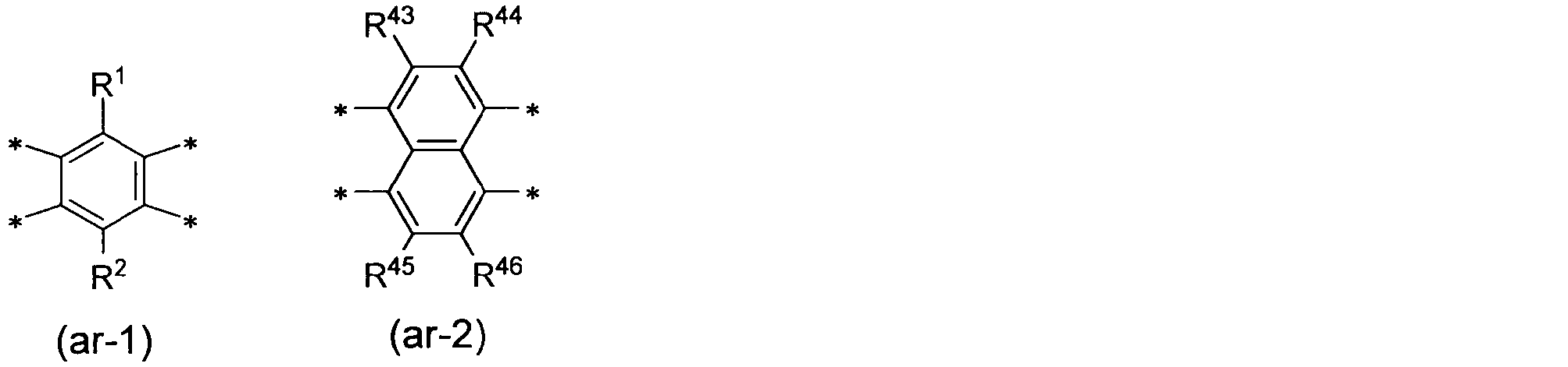
で表される部分構造であり、R1~R10及びR43~R46のうち少なくとも一つは酸性官能基を有する1価の基であり、残りは、それぞれ独立して、水素原子、ハロゲン原子又は1価の有機基である。kは0又は1である。ただし、式(0)中に酸性官能基を少なくとも1個有する。)
<3>酸性官能基を有する重合体(P)と、水と、塩基性モノマー及び塩基発生剤よりなる群から選ばれる少なくとも一種である化合物(A)と、を含有する、リオトロピック液晶性を示す液晶配向剤。
<4>上記<1>の組成物を液晶相の状態で基材上に塗布し、前記重合体(P)を配向させた状態で乾燥する工程を含む、有機膜の製造方法。
<5>上記<1>の組成物において感光性化合物を含有する組成物を液晶相の状態で基材上に塗布し、前記重合体(P)を配向させた状態で乾燥することにより液晶配向膜を形成する工程と、前記液晶配向膜の一部を露光する工程と、前記露光された液晶配向膜を現像する工程と、を含む、パターン化液晶配向膜の製造方法。
<6>上記<1>の組成物を用いて形成された液晶配向膜。
<7>上記<1>の組成物を用いて形成された偏光板。
<8>上記<6>の液晶配向膜を備える位相差板。
<9>複数のアンテナ単位を有するアレイ型の液晶アンテナであって、上記<6>の液晶配向膜を備える、アレイアンテナ。
<10>上記<6>の液晶配向膜を備える液晶素子。
<1>酸性官能基を有する重合体(P)と、水と、塩基性モノマー及び塩基発生剤よりなる群から選ばれる少なくとも一種である化合物(A)と、を含有する、リオトロピック液晶性を示す組成物。
<2>下記式(0)で表される部分構造を有する重合体(P)と、水と、塩基性モノマー及び塩基発生剤よりなる群から選ばれる少なくとも一種である化合物(A)と、を含有する、組成物。
<3>酸性官能基を有する重合体(P)と、水と、塩基性モノマー及び塩基発生剤よりなる群から選ばれる少なくとも一種である化合物(A)と、を含有する、リオトロピック液晶性を示す液晶配向剤。
<4>上記<1>の組成物を液晶相の状態で基材上に塗布し、前記重合体(P)を配向させた状態で乾燥する工程を含む、有機膜の製造方法。
<5>上記<1>の組成物において感光性化合物を含有する組成物を液晶相の状態で基材上に塗布し、前記重合体(P)を配向させた状態で乾燥することにより液晶配向膜を形成する工程と、前記液晶配向膜の一部を露光する工程と、前記露光された液晶配向膜を現像する工程と、を含む、パターン化液晶配向膜の製造方法。
<6>上記<1>の組成物を用いて形成された液晶配向膜。
<7>上記<1>の組成物を用いて形成された偏光板。
<8>上記<6>の液晶配向膜を備える位相差板。
<9>複数のアンテナ単位を有するアレイ型の液晶アンテナであって、上記<6>の液晶配向膜を備える、アレイアンテナ。
<10>上記<6>の液晶配向膜を備える液晶素子。
本開示によれば、光学特性や電気特性等の性能に優れた光学異方性を示す有機膜を簡易な塗布プロセスによって形成することができる。また、組成物中の重合体成分を簡易な塗布プロセスによって大面積で均一に配向させることができ、液晶配向膜や位相差板、偏光板等を低コストで形成することができる。
≪組成物≫
本開示の1つの実施形態において、組成物は、リオトロピック液晶性を示す組成物(以下、「リオトロピック液晶性組成物」ともいう。)である。リオトロピック液晶性組成物は、酸性官能基を有する重合体(P)と、水と、塩基性モノマー及び塩基発生剤よりなる群から選ばれる少なくとも一種の化合物(A)と、を含有する。また、本開示の1つの実施形態において、組成物は、下記式(0)で表される部分構造を有する重合体と、水と、上記化合物(A)とを含有する。以下に、本開示の組成物に含まれる各成分、及び必要に応じて任意に配合されるその他の成分について説明する。
本開示の1つの実施形態において、組成物は、リオトロピック液晶性を示す組成物(以下、「リオトロピック液晶性組成物」ともいう。)である。リオトロピック液晶性組成物は、酸性官能基を有する重合体(P)と、水と、塩基性モノマー及び塩基発生剤よりなる群から選ばれる少なくとも一種の化合物(A)と、を含有する。また、本開示の1つの実施形態において、組成物は、下記式(0)で表される部分構造を有する重合体と、水と、上記化合物(A)とを含有する。以下に、本開示の組成物に含まれる各成分、及び必要に応じて任意に配合されるその他の成分について説明する。
なお、本明細書において「炭化水素基」とは、鎖状炭化水素基、脂環式炭化水素基及び芳香族炭化水素基を含む意味である。「鎖状炭化水素基」とは、主鎖に環状構造を含まず、鎖状構造のみで構成された直鎖状炭化水素基及び分岐状炭化水素基を意味する。ただし、飽和でも不飽和でもよい。「脂環式炭化水素基」とは、環構造としては脂環式炭化水素の構造のみを含み、芳香環構造を含まない炭化水素基を意味する。ただし、脂環式炭化水素の構造のみで構成されている必要はなく、その一部に鎖状構造を有するものも含む。「芳香族炭化水素基」とは、環構造として芳香環構造を含む炭化水素基を意味する。ただし、芳香環構造のみで構成されている必要はなく、その一部に鎖状構造や脂環式炭化水素の構造を含んでいてもよい。「有機基」とは、炭化水素基を含む基を意味し、構造中にヘテロ原子を含んでいてもよい。
<重合体(P)>
重合体(P)が有する酸性官能基は、水中でイオンを形成する官能基である。酸性官能基としては、水を含む溶剤に対する重合体(P)の溶解性をより高くできる点で、スルホン酸基、ホスホン酸基若しくはカルボン酸基、又はそれらが中和された塩であることが好ましく、特にスルホン酸基又はその塩であることが好ましい。
重合体(P)が有する酸性官能基は、水中でイオンを形成する官能基である。酸性官能基としては、水を含む溶剤に対する重合体(P)の溶解性をより高くできる点で、スルホン酸基、ホスホン酸基若しくはカルボン酸基、又はそれらが中和された塩であることが好ましく、特にスルホン酸基又はその塩であることが好ましい。
酸性官能基が塩である場合、対イオンとしては、例えばLi+、Na+、K+、Rb+、Cs+、Cu+、Ag+、アンモニウムイオン、ピリジニウムイオン、イミダゾリウムイオン、グアニジニウムイオン、ホスホニウムイオン等が挙げられる。ただし、対イオンが無機イオンである場合、有機配位子によって錯形成されていてもよく、対イオンが有機イオンである場合、有機基によって修飾されていてもよい。酸性官能基がカルボン酸基である場合、カルボン酸の酸解離定数が低く、酸性条件でプロトンが解離しにくくイオン性が低下するため、強塩基と塩を形成していることが好ましい。
重合体(P)が有する酸性官能基の量は、光学異方性を示す有機膜の光学特性及び電気特性をより良好にする観点、具体的には、重合体(P)に溶解性及びリオトロピック液晶性を十分に付与する観点から、重合体(P)を構成する繰り返し単位100モル部に対し、好ましくは50モル部以上であり、より好ましくは100モル部以上である。また、酸性官能基の上限値については特に制限されず、任意に設定することができる。合成容易性の観点から、酸性官能基の含有量は、重合体(P)を構成する繰り返し単位100モル部に対し、好ましくは300モル部以下、より好ましくは200モル部以下である。なお、重合体(P)が有する酸性官能基は、1種でもよく2種以上でもよい。
重合体(P)としては、液晶性を有し自己組織化できる水溶性ポリマーを用いることができる。重合体(P)は、水を含む溶剤中でリオトロピック液晶性を示すことが好ましい。重合体(P)の主鎖は特に限定されないが、例えばポリイミド、ポリアミック酸、ポリアミック酸エステル、ポリアミド、ポリイミドアミド、ポリキシリレン、ポリパラフェニレン、ポリパラフェニレンビニレン、ポリペプチド、セルロース等が挙げられる。これらのうち、液晶に対する配向規制力に優れている点で、重合体(P)は、ポリイミドであることが好ましい。
温度、溶剤及び濃度において温和な条件でリオトロピック液晶性を示す点で、重合体(P)は、下記式(0)で表される部分構造を有する重合体(以下、「重合体(PI)」ともいう。)であることが好ましく、下記式(1)で表される部分構造を有する重合体であることが特に好ましい。重合体(PI)と水との混合物によれば、重合体(PI)が有する酸性官能基により水に溶解し、剛直棒状骨格に由来する排除体積効果及び酸性官能基に由来する静電反発を駆動力とした自己組織化が促進され、希薄水溶液においても液晶性の発現及び配向秩序度の増大に寄与すると推測される。

(式(0)中、A1は、下記式(ar-1)又は式(ar-2)
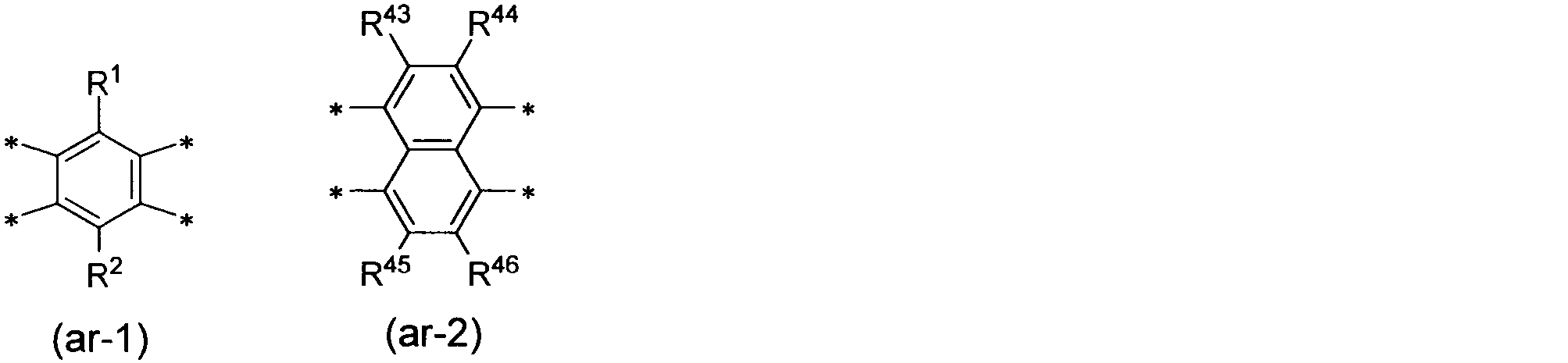
で表される部分構造であり、R1~R10及びR43~R46のうち少なくとも一つは酸性官能基を有する1価の基であり、残りは、それぞれ独立して、水素原子、ハロゲン原子又は1価の有機基である。kは0又は1である。ただし、式(0)中に酸性官能基を少なくとも1個有する。)

(式(1)中、R1~R10のうち少なくとも一つは酸性官能基を有する1価の基であり、残りは、それぞれ独立して、水素原子、ハロゲン原子又は1価の有機基である。kは0又は1である。ただし、式(1)中に酸性官能基を少なくとも1個有する。)
上記式(0)及び式(1)中のR1~R10、R43~R46について、1価の有機基は、好ましくは炭化水素基であり、より好ましくは炭素数1~5のアルキル基である。酸性官能基を有する1価の基は、「*-L1-X1」(ただし、L1は単結合又は2価の連結基であり、X1は酸性官能基である。「*」はベンゼン環に結合する結合手であることを表す。)で表すことができる。ここで、L1が2価の連結基である場合、L1の具体例としては、炭素数1~5のアルカンジイル基、当該アルカンジイル基の炭素-炭素結合間に-O-を含む基、-O-R13-**(ただし、R13は2価の炭化水素基であり、「**」はX1に結合する結合手であることを表す。)等が挙げられる。L1は、好ましくは単結合又は炭素数1~3のアルカンジイル基であり、より好ましくは単結合である。
上記式(0)で表される部分構造及び上記式(1)で表される部分構造がそれぞれ有する酸性官能基の個数は、好ましくは1~4個であり、より好ましくは1個又は2個である。良好なリオトロピック液晶性を示す点及び材料の選択性の自由度が高い点で、上記式(0)で表される部分構造及び上記式(1)で表される部分構造は、ジアミンに由来する部分構造(すなわち、R3~R10の少なくとも一部)に酸性官能基を有していることが好ましい。上記式(0)で表される部分構造中、A1が上記式(ar-2)で表される部分構造である場合、より低い重合体濃度で液晶性を発現する点で、kは0であることが好ましい。
上記式(0)で表される部分構造の好ましい具体例としては、下記式(A-1)~式(A-8)のそれぞれで表される部分構造等が挙げられる。上記式(1)で表される部分構造の好ましい具体例としては、下記式(A-1)~式(A-4)のそれぞれで表される部分構造等が挙げられる。
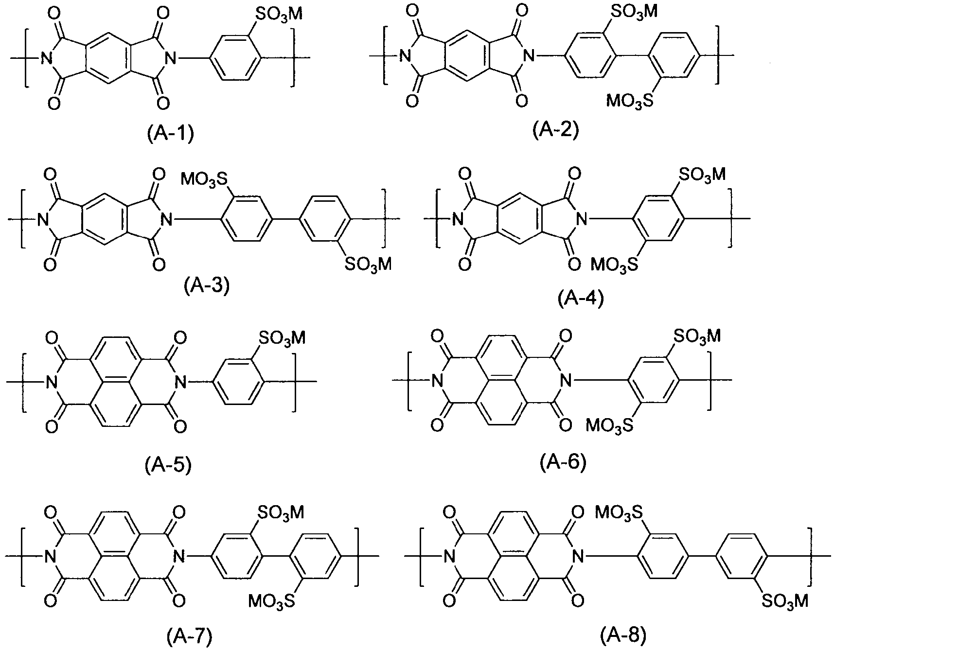
(式(A-1)~式(A-8)中、Mはカチオンである。式中の複数のMは、互いに同一の基又は異なる基である。)
Mのカチオンとしては、酸性官能基が塩である場合の対イオンの例示が適用される。水系の溶剤に対する重合体(PI)の溶解性をより高くできる点で、Mは1価のカチオンが好ましく、これらの中でもアンモニウムイオンが好ましく、第三級アンモニウムイオンがより好ましい。重合体(PI)は、上記式(A-1)~式(A-6)のそれぞれで表される部分構造よりなる群から選ばれる少なくとも一種を有していることが好ましく、上記式(A-1)~式(A-4)のそれぞれで表される部分構造よりなる群から選ばれる少なくとも一種を有していることがより好ましく、上記式(A-1)で表される部分構造及び上記式(A-2)で表される部分構造よりなる群から選ばれる少なくとも一種を有していることが特に好ましい。
重合体(P)において、上記式(0)で表される部分構造の含有量は、重合体(P)が有する繰り返し単位の全量に対して、50モル%以上であることが好ましく、75モル%以上であることがより好ましく、90モル%以上であることがさらに好ましい。重合体(P)が有する繰り返し単位は、上記式(0)で表される部分構造のみであることが特に好ましい。なお、繰り返し単位は、重合体(P)の化学構造の基本単位である。例えば重合体(PI)の繰り返し単位は、テトラカルボン酸誘導体1個とジアミン1個との反応により形成される構造である。
(重合体(P)の合成)
重合体(P)は、その主鎖に応じて、有機化学の定法に従って合成することができる。以下、重合体(PI)について説明する。重合体(PI)は、テトラカルボン酸二無水物、テトラカルボン酸ジエステル及びテトラカルボン酸ジエステルジハロゲン化物よりなる群から選ばれる少なくとも一種のテトラカルボン酸誘導体と、ジアミンとを原料組成に用いた重合により得られるポリイミド前駆体をイミド化することにより得ることができる。
重合体(P)は、その主鎖に応じて、有機化学の定法に従って合成することができる。以下、重合体(PI)について説明する。重合体(PI)は、テトラカルボン酸二無水物、テトラカルボン酸ジエステル及びテトラカルボン酸ジエステルジハロゲン化物よりなる群から選ばれる少なくとも一種のテトラカルボン酸誘導体と、ジアミンとを原料組成に用いた重合により得られるポリイミド前駆体をイミド化することにより得ることができる。
なお、本明細書において「テトラカルボン酸ジエステル」とは、テトラカルボン酸が有する4個のカルボキシル基のうち2個がエステル化され、残りの2個がカルボキシル基である化合物を意味する。「テトラカルボン酸ジエステルジハロゲン化物」とは、テトラカルボン酸が有する4個のカルボキシル基のうち2個がエステル化され、残りの2個がハロゲン化された化合物を意味する。「ポリイミド前駆体」には、ポリアミック酸及びポリアミック酸エステルが含まれる。
重合体(PI)の合成に際し、テトラカルボン酸二無水物としては、下記式(t-1)で表される化合物及び下記式(t-2)で表される化合物よりなる群から選ばれる少なくとも一種の化合物(以下、「特定酸二無水物」ともいう。)を使用することが好ましく、下記式(t-1)で表される化合物を使用することがより好ましい。

(式(t-1)中、R1及びR2は、それぞれ独立に水素原子、ハロゲン原子、酸性官能基又は1価の有機基である。式(t-2)中、R43~R46は、それぞれ独立に水素原子、ハロゲン原子、酸性官能基又は1価の有機基である。)
上記式(t-1)中のR1及びR2並びに上記式(t-2)中のR43~R46において、1価の有機基としては、炭素数1~20の炭化水素基、当該炭化水素基が有する水素原子が酸性官能基で置換された基等が挙げられる。これらのうち、R1、R2、R43~R46は、水素原子、ハロゲン原子、メチル基又はトリフルオロメチル基であることが好ましく、水素原子であることがより好ましい。なお、特定酸二無水物は、1種を単独で又は2種以上を組み合わせて使用することができる。
重合体(PI)の合成に際して使用するテトラカルボン酸ジエステルの好ましい具体例としては、上記式(t-1)又は上記式(t-2)で表されるテトラカルボン酸二無水物を、メタノールやエタノール等のアルコール類を用いて開環して得られる化合物等が挙げられる。重合体(PI)の合成に際して使用するテトラカルボン酸ジエステルジハロゲン化物の好ましい具体例としては、上記テトラカルボン酸ジエステルを、塩化チオニル等の塩素化剤と反応させて得られる化合物等が挙げられる。なお、テトラカルボン酸ジエステル及びテトラカルボン酸ジエステルジハロゲン化物は、それぞれ1種を単独で又は2種以上を組み合わせて使用することができる。
重合体(PI)の合成に際し、ジアミンとしては、酸性官能基を有するジアミン(以下、「特定ジアミン」ともいう。)を用いることが好ましく、酸性官能基を有する芳香族ジアミンを用いることがより好ましい。特定ジアミンの好ましい具体例としては、下記式(d-1)~(d-9)のそれぞれで表される化合物が挙げられる。なお、特定ジアミンは、1種を単独で又は2種以上を組み合わせて使用できる。
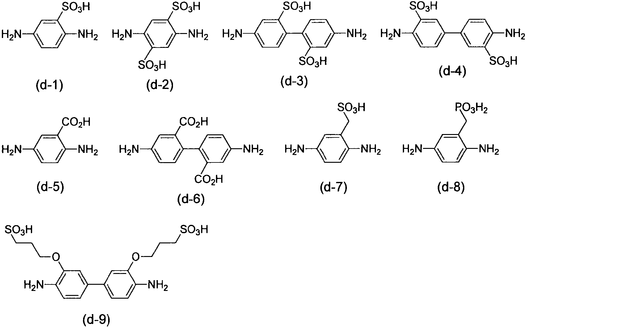
[ポリアミック酸]
重合体(PI)の前駆体であるポリアミック酸(以下、「ポリアミック酸(P)」ともいう。)は、例えばテトラカルボン酸二無水物とジアミンとを反応させることにより得ることができる。具体的には、[i]テトラカルボン酸二無水物とジアミンとを直接反応させる方法;[ii]テトラカルボン酸二無水物又はジアミンを塩基で中和した後に、テトラカルボン酸二無水物とジアミンとを反応させる方法、などが挙げられる。
重合体(PI)の前駆体であるポリアミック酸(以下、「ポリアミック酸(P)」ともいう。)は、例えばテトラカルボン酸二無水物とジアミンとを反応させることにより得ることができる。具体的には、[i]テトラカルボン酸二無水物とジアミンとを直接反応させる方法;[ii]テトラカルボン酸二無水物又はジアミンを塩基で中和した後に、テトラカルボン酸二無水物とジアミンとを反応させる方法、などが挙げられる。
重合体(PI)の合成に際しては、特定酸二無水物以外のテトラカルボン酸二無水物(以下、「その他の酸二無水物」ともいう)、特定ジアミン以外のジアミン(以下、「その他のジアミン」ともいう。)を併用することもできる。
(その他の酸二無水物)
その他の酸二無水物としては、例えば脂肪族テトラカルボン酸二無水物、脂環式テトラカルボン酸二無水物、芳香族テトラカルボン酸二無水物などを挙げることができる。これらの具体例としては、脂肪族テトラカルボン酸二無水物として、例えばブタンテトラカルボン酸二無水物、エチレンジアミン四酢酸二無水物などを;脂環式テトラカルボン酸二無水物として、例えば1,2,3,4-シクロブタンテトラカルボン酸二無水物、1,2,4,5-シクロヘキサンテトラカルボン酸二無水物などを;芳香族テトラカルボン酸二無水物として、例えばナフタレン-2,3,6,7-テトラカルボン酸二無水物、4,4’-ビフタル酸二無水物などを、それぞれ挙げることができるほか、特開2010-97188号公報に記載のテトラカルボン酸二無水物を用いることができる。なお、その他の酸二無水物は、これらの1種を単独で又は2種以上を組み合わせて使用することができる。
(その他の酸二無水物)
その他の酸二無水物としては、例えば脂肪族テトラカルボン酸二無水物、脂環式テトラカルボン酸二無水物、芳香族テトラカルボン酸二無水物などを挙げることができる。これらの具体例としては、脂肪族テトラカルボン酸二無水物として、例えばブタンテトラカルボン酸二無水物、エチレンジアミン四酢酸二無水物などを;脂環式テトラカルボン酸二無水物として、例えば1,2,3,4-シクロブタンテトラカルボン酸二無水物、1,2,4,5-シクロヘキサンテトラカルボン酸二無水物などを;芳香族テトラカルボン酸二無水物として、例えばナフタレン-2,3,6,7-テトラカルボン酸二無水物、4,4’-ビフタル酸二無水物などを、それぞれ挙げることができるほか、特開2010-97188号公報に記載のテトラカルボン酸二無水物を用いることができる。なお、その他の酸二無水物は、これらの1種を単独で又は2種以上を組み合わせて使用することができる。
(その他のジアミン)
その他のジアミンとしては、例えば脂肪族ジアミン、脂環式ジアミン、芳香族ジアミン、ジアミノオルガノシロキサンなどを挙げることができる。これらの具体例としては、脂肪族ジアミンとして、例えばメタキシリレンジアミン、ヘキサメチレンジアミンなどを;脂環式ジアミンとして、例えば1,4-ジアミノシクロヘキサン、4,4’-メチレンビス(シクロヘキシルアミン)などを;芳香族ジアミンとして、例えばp-フェニレンジアミン、2,4-ジアミノベンゼンスルホン酸、3,5-ジアミノ安息香酸、4,4’-ジアミノスチルベン-2,2’-ジスルホン酸、2,2’-ジメチル-4,4’-ジアミノビフェニル、などを;ジアミノオルガノシロキサンとして、例えば、1,3-ビス(3-アミノプロピル)-テトラメチルジシロキサンなどを;それぞれ挙げることができるほか、特開2010-97188号公報に記載のジアミンを用いることができる。
その他のジアミンとしては、例えば脂肪族ジアミン、脂環式ジアミン、芳香族ジアミン、ジアミノオルガノシロキサンなどを挙げることができる。これらの具体例としては、脂肪族ジアミンとして、例えばメタキシリレンジアミン、ヘキサメチレンジアミンなどを;脂環式ジアミンとして、例えば1,4-ジアミノシクロヘキサン、4,4’-メチレンビス(シクロヘキシルアミン)などを;芳香族ジアミンとして、例えばp-フェニレンジアミン、2,4-ジアミノベンゼンスルホン酸、3,5-ジアミノ安息香酸、4,4’-ジアミノスチルベン-2,2’-ジスルホン酸、2,2’-ジメチル-4,4’-ジアミノビフェニル、などを;ジアミノオルガノシロキサンとして、例えば、1,3-ビス(3-アミノプロピル)-テトラメチルジシロキサンなどを;それぞれ挙げることができるほか、特開2010-97188号公報に記載のジアミンを用いることができる。
ポリアミック酸(P)の合成に際し、特定酸二無水物を使用することによりポリアミック酸(P)にリオトロピック液晶性を付与する場合、特定酸二無水物の使用割合は、ポリアミック酸(P)にリオトロピック液晶性を十分に付与する観点から、ポリアミック酸(P)の合成に使用するテトラカルボン酸二無水物の全体量に対し、50モル%以上とすることが好ましく、75モル%以上とすることがより好ましく、90モル%以上とすることが特に好ましい。当該使用割合の上限値は特に制限されず、100モル%以下の範囲で任意に設定できる。
特定ジアミンの使用割合は、ポリアミック酸(P)に対し、水系溶剤への溶解性及びリオトロピック液晶性を十分に付与する観点から、ポリアミック酸(P)の合成に使用するジアミンの全体量に対し、50モル%以上とすることが好ましく、75モル%以上とすることがさらに好ましく、90モル%以上とすることがさらに好ましく、100モル%とすることが特に好ましい。
(ポリアミック酸の合成)
ポリアミック酸(P)は、上記のようなテトラカルボン酸二無水物とジアミンとを、必要に応じて分子量調整剤とともに反応させることによって得ることができる。ポリアミック酸(P)の合成反応に供されるテトラカルボン酸二無水物とジアミンとの使用割合は、ジアミンのアミノ基1当量に対して、テトラカルボン酸二無水物の酸無水物基が0.5~2当量となる割合が好ましく、0.8~1.2当量となる割合がより好ましい。
ポリアミック酸(P)は、上記のようなテトラカルボン酸二無水物とジアミンとを、必要に応じて分子量調整剤とともに反応させることによって得ることができる。ポリアミック酸(P)の合成反応に供されるテトラカルボン酸二無水物とジアミンとの使用割合は、ジアミンのアミノ基1当量に対して、テトラカルボン酸二無水物の酸無水物基が0.5~2当量となる割合が好ましく、0.8~1.2当量となる割合がより好ましい。
酸性官能基を有するモノマーを塩基で中和した後に、テトラカルボン酸二無水物とジアミンとを反応させる場合(上記[ii]の場合)、種々の塩基を用いることができるが、有機溶媒中での溶解性を担保する観点で、有機塩基が好ましく、第三級アミンがより好ましく、トリエチルアミンが特に好ましい。塩基の使用割合は、酸性官能基に対して0.5~5当量となる割合が好ましく、1~2当量となる割合がさらに好ましい。分子量調整剤としては、例えば無水マレイン酸、無水フタル酸、無水イタコン酸などの酸一無水物、アニリン、シクロヘキシルアミン、n-ブチルアミンなどのモノアミン化合物、フェニルイソシアネート、ナフチルイソシアネートなどのモノイソシアネート化合物等が挙げられる。分子量調整剤の使用割合は、使用するテトラカルボン酸二無水物及びジアミンの合計100質量部に対して、好ましくは20質量部以下であり、より好ましくは10質量部以下である。
ポリアミック酸(P)の合成反応は、好ましくは有機溶媒中において行われる。このときの反応温度は、-20℃~150℃が好ましく、0~100℃がより好ましい。また、反応時間は、0.1~24時間が好ましく、0.5~12時間がより好ましい。
反応に使用する有機溶媒としては、例えば非プロトン性極性溶媒、フェノール系溶媒、アルコール、ケトン、エステル、エーテル、ハロゲン化炭化水素、炭化水素などを挙げることができる。これらの有機溶媒のうち、非プロトン性極性溶媒及びフェノール系溶媒よりなる群(第一群の有機溶媒)から選択される1種以上、又は、第一群の有機溶媒から選択される1種以上と、アルコール、ケトン、エステル、エーテル、ハロゲン化炭化水素及び炭化水素よりなる群(第二群の有機溶媒)から選択される1種以上との混合物を使用することが好ましい。後者の場合、第二群の有機溶媒の使用割合は、第一群の有機溶媒及び第二群の有機溶媒の合計量に対して、好ましくは50質量%以下であり、より好ましくは40質量%以下であり、更に好ましくは30質量%以下である。
特に好ましい有機溶媒は、N-メチル-2-ピロリドン、N,N-ジメチルアセトアミド、N,N-ジメチルホルムアミド、ジメチルスルホキシド、γ-ブチロラクトン、テトラメチル尿素、ヘキサメチルホスホルトリアミド、m-クレゾール、キシレノール及びハロゲン化フェノールよりなる群から選択される1種以上を溶媒として使用するか、あるいはこれらの1種以上と他の有機溶媒との混合物を、上記割合の範囲で使用することが好ましい。有機溶媒の使用量(a)は、テトラカルボン酸二無水物及びジアミンの合計量(b)が、反応溶液の全量(a+b)に対して、1~50質量%になる量とすることが好ましい。ポリアミック酸(P)を含有する反応溶液は、そのまま脱水閉環反応に供してもよく、ポリアミック酸(P)を単離したうえで脱水閉環反応に供してもよい。
[ポリアミック酸エステル]
重合体(PI)前駆体であるポリアミック酸エステル(以下、「ポリアミック酸エステル(P)」ともいう。)は、例えば、[I]上記重合反応により得られたポリアミック酸(P)とエステル化剤とを反応させる方法、[II]テトラカルボン酸ジエステルとジアミンとを反応させる方法、[III]テトラカルボン酸ジエステルジハロゲン化物とジアミンとを反応させる方法、などによって得ることができる。
重合体(PI)前駆体であるポリアミック酸エステル(以下、「ポリアミック酸エステル(P)」ともいう。)は、例えば、[I]上記重合反応により得られたポリアミック酸(P)とエステル化剤とを反応させる方法、[II]テトラカルボン酸ジエステルとジアミンとを反応させる方法、[III]テトラカルボン酸ジエステルジハロゲン化物とジアミンとを反応させる方法、などによって得ることができる。
[イミド化]
重合体(PI)は、上記の如くして合成されたポリイミド前駆体を脱水閉環してイミド化することにより得ることができる。重合体(PI)は、その前駆体であるポリイミド前駆体が有していたアミック酸構造又はアミック酸エステル構造のすべてを脱水閉環した完全イミド化物であってもよく、アミック酸構造及びアミック酸エステル構造の一部のみを脱水閉環し、アミック酸構造又はアミック酸エステル構造とイミド環構造とが併存する部分イミド化物であってもよい。重合体(PI)は、液晶素子の用途において配向規制力及び電圧保持率が十分に高い有機膜を得る観点から、そのイミド化率が50%以上であることが好ましく、75%以上であることがより好ましく、90%以上であることがさらに好ましく、95%以上であることが特に好ましい。このイミド化率は、ポリイミドのアミック酸構造及びアミック酸エステル構造の数とイミド環構造の数との合計に対するイミド環構造の数の占める割合を百分率で表したものである。
重合体(PI)は、上記の如くして合成されたポリイミド前駆体を脱水閉環してイミド化することにより得ることができる。重合体(PI)は、その前駆体であるポリイミド前駆体が有していたアミック酸構造又はアミック酸エステル構造のすべてを脱水閉環した完全イミド化物であってもよく、アミック酸構造及びアミック酸エステル構造の一部のみを脱水閉環し、アミック酸構造又はアミック酸エステル構造とイミド環構造とが併存する部分イミド化物であってもよい。重合体(PI)は、液晶素子の用途において配向規制力及び電圧保持率が十分に高い有機膜を得る観点から、そのイミド化率が50%以上であることが好ましく、75%以上であることがより好ましく、90%以上であることがさらに好ましく、95%以上であることが特に好ましい。このイミド化率は、ポリイミドのアミック酸構造及びアミック酸エステル構造の数とイミド環構造の数との合計に対するイミド環構造の数の占める割合を百分率で表したものである。
ポリイミド前駆体の脱水閉環は、好ましくはポリアミック酸を加熱する方法により、又はポリアミック酸を有機溶媒に溶解し、この溶液中に脱水剤及び脱水閉環触媒の少なくともいずれかを添加して必要に応じて加熱する方法により行われる。
ポリアミック酸の溶液中に脱水剤及び脱水閉環触媒を添加する方法において、脱水剤としては、例えば無水酢酸、無水プロピオン酸、無水トリフルオロ酢酸等の酸無水物を用いることができる。脱水剤の使用量は、ポリアミック酸のアミック酸構造の1モルに対して0.01~20モルとすることが好ましい。脱水閉環触媒としては、例えばピリジン、トリエチルアミン、1-メチルピペリジン等の塩基触媒、メタンスルホン酸、安息香酸等の酸触媒を用いることができる。脱水閉環触媒の使用量は、使用する脱水剤1モルに対して0.01~10モルとすることが好ましい。脱水閉環反応に用いられる有機溶媒としては、ポリアミック酸(P)の合成に用いられるものとして例示した有機溶媒を挙げることができる。脱水閉環反応の反応温度は、好ましくは0~200℃であり、反応時間は、好ましくは1.0~120時間である。重合体を含有する反応溶液については、そのまま組成物の調製に供してもよく、重合体を単離したうえで組成物の調製に供してもよい。
[重合体(P)の物性]
重合体(P)は、重合体(P)を濃度10質量%の溶液としたときに、10~2000mPa・sの溶液粘度を持つものであることが好ましく、20~1000mPa・sの溶液粘度を持つものであることがより好ましい。なお、上記重合体の溶液粘度(mPa・s)は、当該重合体の良溶媒(例えば水など)を用いて調製した濃度10質量%の重合体溶液につき、E型回転粘度計を用いて25℃において測定した値である。
重合体(P)は、重合体(P)を濃度10質量%の溶液としたときに、10~2000mPa・sの溶液粘度を持つものであることが好ましく、20~1000mPa・sの溶液粘度を持つものであることがより好ましい。なお、上記重合体の溶液粘度(mPa・s)は、当該重合体の良溶媒(例えば水など)を用いて調製した濃度10質量%の重合体溶液につき、E型回転粘度計を用いて25℃において測定した値である。
重合体(P)のゲルパーミエーションクロマトグラフィー(GPC)により測定したポリスチレン換算の重量平均分子量(Mw)は、好ましくは1,000以上であり、より好ましくは2,000以上である。また、Mwは、好ましくは500,000以下であり、より好ましくは100,000以下である。Mwと、GPCにより測定したポリスチレン換算の数平均分子量(Mn)との比で表される分子量分布(Mw/Mn)は、好ましくは10以下であり、より好ましくは5以下である。このような分子量範囲にあることで、上記組成物がリオトロピック液晶性を示す濃度範囲及び温度範囲を確保しやすくすることができる。
重合体(P)は、0℃以上100℃未満の範囲の少なくとも一部の温度でリオトロピック液晶性を示すことが好ましい。重合体(P)がリオトロピック液晶性を示す温度範囲は、0℃以上100℃未満の範囲のうち、好ましくは20~40℃を含む温度範囲であり、より好ましくは20~60℃を含む温度範囲であり、さらに好ましくは20~80℃を含む温度範囲である。
<水>
本組成物は、水溶性の重合体(P)が水系溶媒に溶解された液状の組成物である。重合体(P)の酸性官能基が解離して電荷を持ち、分子間の静電反発を誘起し、より低濃度においても液晶性を発現するようにする観点から、水の含有割合は、組成物に含まれる溶媒の全体量(100質量%)に対し、好ましくは40質量%以上であり、より好ましくは60質量%以上であり、さらに好ましくは80質量%以上である。水の含有割合は、組成物に含まれる溶媒の全量に対し、100質量%以下とすることができる。
本組成物は、水溶性の重合体(P)が水系溶媒に溶解された液状の組成物である。重合体(P)の酸性官能基が解離して電荷を持ち、分子間の静電反発を誘起し、より低濃度においても液晶性を発現するようにする観点から、水の含有割合は、組成物に含まれる溶媒の全体量(100質量%)に対し、好ましくは40質量%以上であり、より好ましくは60質量%以上であり、さらに好ましくは80質量%以上である。水の含有割合は、組成物に含まれる溶媒の全量に対し、100質量%以下とすることができる。
<化合物(A)>
(塩基性モノマー)
塩基性モノマーとしては、重合性基と塩基性官能基とを有する水溶性の化合物であればよく、その他の構造は特に制限されない。塩基性モノマーが有する重合性基は、ラジカル重合性基であることが好ましく、炭素-炭素不飽和結合を有する基であることがより好ましい。特に好ましくは、(メタ)アクリロイル基又はビニル基である。なお、本明細書において「(メタ)アクリロイル」は「アクリロイル」及び「メタクリロイル」を包含する意味である。
(塩基性モノマー)
塩基性モノマーとしては、重合性基と塩基性官能基とを有する水溶性の化合物であればよく、その他の構造は特に制限されない。塩基性モノマーが有する重合性基は、ラジカル重合性基であることが好ましく、炭素-炭素不飽和結合を有する基であることがより好ましい。特に好ましくは、(メタ)アクリロイル基又はビニル基である。なお、本明細書において「(メタ)アクリロイル」は「アクリロイル」及び「メタクリロイル」を包含する意味である。
塩基性官能基は、重合体(P)が有する酸性官能基と酸-塩基相互作用し得る官能基である。塩基性モノマーが有する塩基性官能基と、重合体(P)が有する酸性官能基とが相互作用して膜中でポリイオンコンプレックスが形成されることにより、液晶配向膜の力学特性及び耐水性を向上させることができる。また、液晶素子の電気特性の向上を図ることができる。塩基性官能基は、窒素原子を含む官能基であることが好ましい。なお、塩基性官能基は、組成物中において、プロトン化されていてもよく、アルキル化されていてもよく、あるいは重合体(P)が有する酸性官能基の対イオンとなっていてもよい。
塩基性官能基が窒素原子を含む官能基である場合の具体例としては、1級アミノ基(-NH2)、2級アミノ基(-NHR20)、3級アミノ基(-NR21R22)、ピリジル基、イミダゾイル基、グアニジノ基等が挙げられる。ここで、R20、R21及びR22は、それぞれ独立して炭素数1~10の1価の炭化水素基である。R20、R21及びR22は、好ましくは炭素数1~5のアルキル基である。これらのうち、塩基性官能基は、重合体(P)の液晶配向性をより優れたものとすることができる点で非環状構造である基が好ましく、組成物の保存安定性を良好にできる点で3級アミノ基がより好ましい。
塩基性モノマー中の塩基性官能基の数は、1個でもよいし複数個でもよい。イオン架橋を膜中に適度に形成させ、優れた液晶配向性及び電気特性を示す液晶素子を得ることができる点で、塩基性モノマー1分子が有する塩基性官能基の数は、好ましくは1個又は2個であり、より好ましくは1個である。なお、単官能性の塩基性モノマーと多官能性の塩基性モノマーとを併用してもよい。
塩基性モノマーとしては、(メタ)アクリロイル基含有化合物及びビニル基含有化合物よりなる群から選択される少なくとも一種を好ましく使用できる。これらのうち、(メタ)アクリロイル基含有化合物がより好ましく、下記式(5)で表される化合物を特に好ましく使用できる。

(式(5)中、R30は水素原子又はメチル基であり、X2は-NH-又は-O-である。R31は、炭素数2~10の2価のアルカンジイル基であり、R32及びR33は、それぞれ独立に水素原子又は炭素数1~5のアルキル基であるか、又はR32及びR33が互いに合わせられてR32及びR33が結合する窒素原子と共に構成される環構造を表す。)
上記式(5)において、R31は、直鎖状であることが好ましい。R31の炭素数は、2~8が好ましく、2~5がより好ましい。R32及びR33が互いに合わせられて構成される環構造としては、ピロリジン環、ピペリジン環、モルホリン環等が挙げられる。
塩基性モノマーの具体例としては、例えば下記式(4-1)~式(4-6)のそれぞれで表される化合物等が挙げられる。なお、塩基性モノマーとしては、1種を単独で又は2種以上を組み合わせて使用できる。

上記組成物において、塩基性モノマーの配合割合は、液晶素子の液晶配向性及び電気特性の改善効果を十分に得る観点から、重合体(P)が有する酸性官能基の全量に対し、好ましくは0.2モル当量以上であり、より好ましくは0.5モル当量以上であり、さらに好ましくは0.8モル当量以上である。また、塩基性モノマーの配合割合は、過剰な塩基性ポリマーの生成による性能低下を抑制する観点から、重合体(P)が有する酸性官能基の全量に対し、好ましくは2.0モル当量以下であり、より好ましくは1.5モル当量以下であり、さらに好ましくは1.0モル当量以下である。
(塩基発生剤)
塩基発生剤は、熱及び光の少なくとも一方が付与されることによって塩基を発生する化合物である。塩基発生剤としては、入手容易性の観点から熱塩基発生剤を好ましく使用でき、例えば、保護されていてもよい塩基性官能基を複数個有する多官能性化合物(以下、「多官能性塩基」ともいう。)、イオン型塩基等が挙げられる。多官能性塩基が有する塩基性官能基は、重合体(P)が有する酸性官能基と酸-塩基相互作用し得る官能基である。多官能性塩基は、窒素原子を有する化合物であることが好ましく、下記式(2)で表される化合物であることがより好ましい。

(式(2)中、R16は(m+n)価の有機基であり、R17は保護基であり、R18は水素原子又は1価の有機基であり、X1は窒素原子を含む塩基性官能基を有する1価の基である。ただし、R18及びX1が互いに合わせられてこれらが結合する原子と共に環構造を形成していてもよい。mは0又は1であり、nは1以上の整数であり、m+n≧2を満たす。)
塩基発生剤は、熱及び光の少なくとも一方が付与されることによって塩基を発生する化合物である。塩基発生剤としては、入手容易性の観点から熱塩基発生剤を好ましく使用でき、例えば、保護されていてもよい塩基性官能基を複数個有する多官能性化合物(以下、「多官能性塩基」ともいう。)、イオン型塩基等が挙げられる。多官能性塩基が有する塩基性官能基は、重合体(P)が有する酸性官能基と酸-塩基相互作用し得る官能基である。多官能性塩基は、窒素原子を有する化合物であることが好ましく、下記式(2)で表される化合物であることがより好ましい。
上記式(2)において、R17としては、カルバメート系保護基、アミド系保護基、イミド系保護基、スルホンアミド系保護基等が挙げられる。これらのうち、好ましくはカルバメート系保護基であり、その具体例としては、例えばtert-ブトキシカルボニル基、ベンジルオキシカルボニル基、1,1-ジメチル-2-ハロエチルオキシカルボニル基、1,1-ジメチル-2-シアノエチルオキシカルボニル基、9-フルオレニルメチルカルボニル基、2-(トリメチルシリル)エトキシカルボニル基等が挙げられる。熱による脱保護が容易である点や、製膜時の加熱によって脱離した基に由来する化合物を気体として膜外に排出可能な点で、好ましくはtert-ブトキシカルボニル基である。
R18の1価の有機基としては、例えば炭素数1~10の1価の炭化水素基、保護基等が挙げられる。R18は、好ましくは水素原子、炭素数1~3のアルキル基又はtert-ブトキシカルボニル基である。
R16としては、例えば炭素数1~20の2価の炭化水素基、炭素数2~20の炭化水素基の炭素-炭素結合間に-O-を有する基、炭素数1~20の2価の炭化水素基の水素原子が-OH、-COOH等の置換基によって置換された基などが挙げられる。R16は、好ましくは炭素数1~20の2価の炭化水素基、又は-OH若しくは-COOHで置換された基である。X1としては、アミノ基、ピリジル基、イミダゾイル基、グアニジノ基等が挙げられる。重合体(P)との酸塩基相互作用を発現させる観点から、mは、好ましくは1である。nは、1~4が好ましく、1又は2がより好ましい。
R16としては、例えば炭素数1~20の2価の炭化水素基、炭素数2~20の炭化水素基の炭素-炭素結合間に-O-を有する基、炭素数1~20の2価の炭化水素基の水素原子が-OH、-COOH等の置換基によって置換された基などが挙げられる。R16は、好ましくは炭素数1~20の2価の炭化水素基、又は-OH若しくは-COOHで置換された基である。X1としては、アミノ基、ピリジル基、イミダゾイル基、グアニジノ基等が挙げられる。重合体(P)との酸塩基相互作用を発現させる観点から、mは、好ましくは1である。nは、1~4が好ましく、1又は2がより好ましい。
塩基発生剤の具体例としては、多官能性塩基として、例えば下記式(2-1)~式(2-6)のそれぞれで表される化合物等を;イオン型塩基として、例えば下記式(3-1)で表される化合物等を、それぞれ挙げることができる。これらのうち、液晶配向膜の力学特性及び耐水性、並びに液晶素子の電気特性の改善効果が高い点で、多官能性塩基を用いることが好ましい。

上記組成物において、塩基発生剤の配合割合は、液晶素子の電気特性の改善効果を十分に得る観点から、上記組成物中に含まれる重合体(P)が有する酸性官能基の全量に対し、塩基発生剤の塩基性官能基が、0.2モル当量以上となる割合であることが好ましく、0.5モル当量以上となる割合であることがより好ましく、0.8モル当量以上となる割合であることがさらに好ましい。また、塩基発生剤の配合割合は、過度な架橋形成による性能低下を抑制する観点から、上記組成物中に含まれる重合体(P)が有する酸性官能基の全量に対し、塩基発生剤の塩基性官能基が、2.0モル当量以下となる割合であることが好ましく、1.5モル当量以下となる割合であることがより好ましく、1.0モル当量以下となる割合であることがさらに好ましい。
<その他の成分>
本組成物は、本開示の目的及び効果を妨げない範囲内において、重合体(P)、水及び化合物(A)以外のその他の成分を含有していてもよい。
本組成物は、本開示の目的及び効果を妨げない範囲内において、重合体(P)、水及び化合物(A)以外のその他の成分を含有していてもよい。
[重合開始剤]
上記組成物が化合物(A)として塩基性モノマーを含有する場合、当該組成物は重合開始剤を更に含有することが好ましい。重合開始剤としては、水溶性の熱重合開始剤及び光重合開始剤を用いることができる。これらの具体例としては、水溶性熱重合開始剤として、4,4’-アゾビス(4-シアノ吉草酸)、2,2’-アゾビス[2-(2-イミダゾリン-2-イル)プロパン]二硫酸塩二水和物、2,2’-アゾビス[2-(2-イミダゾリン-2-イル)プロパン]ジヒドロクロリド、2,2’-アゾビス(2-メチルプロピオンアミジン)ジヒドロクロリド、2,2’-アゾビス[N-(2-カルボキシエチル)-2-メチルプロピオンアミジン]四水和物、2,2’-アゾビス[2-(2-イミダゾリン-2-イル)プロパン]、2,2’-アゾビス[2-メチル-N-(2-ヒドロキシエチル)プロピオンアミド]等を;水溶性光重合開始剤として、例えばフェニル(2,4,6-トリメチルベンゾイル)ホスフィン酸リチウム、2-ヒドロキシ-4’-(2-ヒドロキシエトキ)-2-メチルプロピオフェノン等を、それぞれ挙げることができる。重合開始剤としては1種を単独で用いてもよく、2種以上を組み合わせて用いてもよい。
上記組成物が化合物(A)として塩基性モノマーを含有する場合、当該組成物は重合開始剤を更に含有することが好ましい。重合開始剤としては、水溶性の熱重合開始剤及び光重合開始剤を用いることができる。これらの具体例としては、水溶性熱重合開始剤として、4,4’-アゾビス(4-シアノ吉草酸)、2,2’-アゾビス[2-(2-イミダゾリン-2-イル)プロパン]二硫酸塩二水和物、2,2’-アゾビス[2-(2-イミダゾリン-2-イル)プロパン]ジヒドロクロリド、2,2’-アゾビス(2-メチルプロピオンアミジン)ジヒドロクロリド、2,2’-アゾビス[N-(2-カルボキシエチル)-2-メチルプロピオンアミジン]四水和物、2,2’-アゾビス[2-(2-イミダゾリン-2-イル)プロパン]、2,2’-アゾビス[2-メチル-N-(2-ヒドロキシエチル)プロピオンアミド]等を;水溶性光重合開始剤として、例えばフェニル(2,4,6-トリメチルベンゾイル)ホスフィン酸リチウム、2-ヒドロキシ-4’-(2-ヒドロキシエトキ)-2-メチルプロピオフェノン等を、それぞれ挙げることができる。重合開始剤としては1種を単独で用いてもよく、2種以上を組み合わせて用いてもよい。
重合開始剤の配合割合は、膜中において塩基性モノマーの重合を十分に進行させる観点から、組成物の全量に対し、好ましくは0.001質量%以上であり、より好ましくは0.01質量%以上である。また、重合開始剤の配合割合は、当該組成物の全量に対し、好ましくは1.0質量%以下であり、より好ましくは0.1質量%以下である。
[その他の重合体]
上記組成物は、重合体(P)とは異なる重合体(以下、「その他の重合体」ともいう。)を含有していてもよい。その他の重合体としては、例えば、上記その他のテトラカルボン酸二無水物と上記その他のジアミンとを反応させて得られるポリアミック酸、当該ポリアミック酸のイミド化重合体、当該ポリアミック酸のエステル化重合体、ポリエステル、ポリアミド、セルロース誘導体、ポリアセタール、ポリスチレン誘導体、ポリ(スチレン-フェニルマレイミド)誘導体、ポリ(メタ)アクリレート等が挙げられる。なお、「(メタ)アクリレート」は、「アクリレート」及び「メタクリレート」を包含する意味である。その他の重合体を組成物に配合する場合、その配合割合は、組成物中に含まれる重合体の合計100質量部に対して、好ましくは30質量部以下、より好ましくは10質量部以下、更に好ましくは5質量部以下である。
上記組成物は、重合体(P)とは異なる重合体(以下、「その他の重合体」ともいう。)を含有していてもよい。その他の重合体としては、例えば、上記その他のテトラカルボン酸二無水物と上記その他のジアミンとを反応させて得られるポリアミック酸、当該ポリアミック酸のイミド化重合体、当該ポリアミック酸のエステル化重合体、ポリエステル、ポリアミド、セルロース誘導体、ポリアセタール、ポリスチレン誘導体、ポリ(スチレン-フェニルマレイミド)誘導体、ポリ(メタ)アクリレート等が挙げられる。なお、「(メタ)アクリレート」は、「アクリレート」及び「メタクリレート」を包含する意味である。その他の重合体を組成物に配合する場合、その配合割合は、組成物中に含まれる重合体の合計100質量部に対して、好ましくは30質量部以下、より好ましくは10質量部以下、更に好ましくは5質量部以下である。
[棒状分子等]
上記組成物は、棒状分子又は棒状ナノ構造体(以下、「棒状分子等」ともいう。)を含有していてもよい。上記組成物にせん断応力を加えることで、重合体(P)の一軸配向に伴い、棒状分子等の配向についても制御することができる。棒状分子としては、例えば二色性色素が挙げられ、棒状ナノ構造体としては、例えば色素会合体、量子ロッド、金属ナノロッド、カーボンナノチューブ、タンパク質、核酸、ウィルス等が挙げられる。棒状分子等の配向を制御することにより様々な機能性を付与することができ、これらの中でも、二色性色素、色素会合体、量子ロッド、金属ナノロッド及びカーボンナノチューブよりなる群から選ばれる少なくとも一種を好ましく用いることができる。例えば、二色性色素を含有する組成物によれば、ゲスト-ホスト型の偏光板を形成することができる。量子ロッドを含有する組成物によれば、偏光発光が可能な波長変換板を形成することでき、カーボンナノチューブを含有する組成物によれば、導電異方性を有するワイヤーやアクチュエーターを形成することができる。上記組成物中における棒状分子等の配合割合は、棒状分子等の種類に応じて、本開示の効果を損なわない範囲で適宜設定することができる。
上記組成物は、棒状分子又は棒状ナノ構造体(以下、「棒状分子等」ともいう。)を含有していてもよい。上記組成物にせん断応力を加えることで、重合体(P)の一軸配向に伴い、棒状分子等の配向についても制御することができる。棒状分子としては、例えば二色性色素が挙げられ、棒状ナノ構造体としては、例えば色素会合体、量子ロッド、金属ナノロッド、カーボンナノチューブ、タンパク質、核酸、ウィルス等が挙げられる。棒状分子等の配向を制御することにより様々な機能性を付与することができ、これらの中でも、二色性色素、色素会合体、量子ロッド、金属ナノロッド及びカーボンナノチューブよりなる群から選ばれる少なくとも一種を好ましく用いることができる。例えば、二色性色素を含有する組成物によれば、ゲスト-ホスト型の偏光板を形成することができる。量子ロッドを含有する組成物によれば、偏光発光が可能な波長変換板を形成することでき、カーボンナノチューブを含有する組成物によれば、導電異方性を有するワイヤーやアクチュエーターを形成することができる。上記組成物中における棒状分子等の配合割合は、棒状分子等の種類に応じて、本開示の効果を損なわない範囲で適宜設定することができる。
[溶剤]
本組成物の溶剤成分として、水以外の溶剤(以下、「その他の溶剤」ともいう。)を使用してもよい。その他の溶剤としては、水と均一に混ざり合うことが可能な溶剤であればよく、例えばメタノール、エタノール、n-プロパノール、i-プロパノール、n-ブタノール、エチレングリコール、アセトン、メチルエチルケトン、テトラヒドロフラン、N-メチル-2-ピロリドン、γ-ブチロラクトン、1-ブトキシ-2-プロパノール、ダイアセトンアルコール、ジプロピレングリコールモノメチルエーテル、乳酸エチル、エチレングリコールメチルエーテル、エチレングリコール-n-ブチルエーテル(ブチルセロソルブ)、ジエチレングリコールモノメチルエーテル、ジエチレングリコールモノエチルエーテル、ジエチレングリコールモノメチルエーテルアセテート、ジエチレングリコールモノエチルエーテルアセテート等を挙げることができる。その他の溶剤としては、一種を単独で又は2種以上を混合して使用できる。
本組成物の溶剤成分として、水以外の溶剤(以下、「その他の溶剤」ともいう。)を使用してもよい。その他の溶剤としては、水と均一に混ざり合うことが可能な溶剤であればよく、例えばメタノール、エタノール、n-プロパノール、i-プロパノール、n-ブタノール、エチレングリコール、アセトン、メチルエチルケトン、テトラヒドロフラン、N-メチル-2-ピロリドン、γ-ブチロラクトン、1-ブトキシ-2-プロパノール、ダイアセトンアルコール、ジプロピレングリコールモノメチルエーテル、乳酸エチル、エチレングリコールメチルエーテル、エチレングリコール-n-ブチルエーテル(ブチルセロソルブ)、ジエチレングリコールモノメチルエーテル、ジエチレングリコールモノエチルエーテル、ジエチレングリコールモノメチルエーテルアセテート、ジエチレングリコールモノエチルエーテルアセテート等を挙げることができる。その他の溶剤としては、一種を単独で又は2種以上を混合して使用できる。
溶剤として、水と有機溶媒との混合溶剤を使用する場合、使用する有機溶媒は、水よりも沸点が低い有機溶媒が好ましく、メタノール、エタノール、n-プロパノール、i-プロパノール、アセトン及びテトラヒドロフランよりなる群から選ばれる少なくとも一種であることがより好ましい。水と有機溶媒との混合溶剤を使用する場合、有機溶媒の含有割合は、混合溶剤の全体量に対して、50質量%以下とすることが好ましく、25質量%以下とすることがより好ましく、10質量%以下とすることがさらに好ましい。
その他の成分としては、上記のほか、例えば分子内に少なくとも一つのエポキシ基を有する化合物、官能性シラン化合物、界面活性剤、充填剤、顔料、消泡剤、増感剤、分散剤、酸化防止剤、密着助剤、帯電防止剤、レベリング剤、抗菌剤等が挙げられる。なお、これらの配合割合は、配合する各化合物に応じて、本開示の効果を妨げない範囲で適宜設定することができる。
組成物中の重合体(P)の濃度は、組成物がリオトロピック液晶性を示す濃度であることが好ましい。重合体(P)の濃度は、好ましくは、溶剤と重合体(P)との合計量に対して1~20質量%である。重合体(P)の濃度は、溶剤と重合体(P)との合計量に対して、より好ましくは1~10質量%であり、さらに好ましくは1~5質量%である。特に重合体(PI)によれば、比較的低い重合体濃度でリオトロピック液晶性を示す組成物を得ることができる点で好ましい。このため、基材上に塗膜を形成する際の塗布性が良好であり、膜厚が0.05~0.5μm程度の薄膜を作成でき、工業的生産性に優れている。
組成物の固形分濃度(組成物の溶剤以外の成分の合計質量が組成物の全質量に占める割合)は、粘性、揮発性などを考慮して適宜に選択されるが、好ましくは1~30質量%であり、より好ましくは1~20質量%、特に好ましくは1~10質量%の範囲である。本組成物は、後述するように基材表面に塗布され、好ましくは乾燥されることにより塗膜が形成されることがある。このとき、固形分濃度が1質量%以上であると、組成物がリオトロピック液晶性を示しやすくなる点で好ましい。また、固形分濃度が30質量%以下であると、塗膜の膜厚が適度な厚さとなって良好な塗膜が得やすく、また、組成物の粘性が適度となり塗布性を良好にできる傾向にある。組成物を調製する際の温度は、好ましくは10~90℃であり、より好ましくは20~80℃である。
<有機膜の製造方法>
上記組成物を用いることにより、光学異方性を有する有機膜を得ることができる。当該有機膜は、本組成物を液晶相の状態で基材上に塗布し、せん断応力によって流動させた状態で乾燥する(塗布乾燥工程)。これにより、重合体(P)の分子鎖がせん断方向に自己組織的に一軸配向した塗膜を得ることができる。組成物の塗布は、バーコーター法、アプリケーター法、ダイコーター法又はブレードコーター法により行うことが好ましい。これらの方法は、重合体(P)の分子鎖をせん断応力による流動により配向させやすい点で好ましい。
上記組成物を用いることにより、光学異方性を有する有機膜を得ることができる。当該有機膜は、本組成物を液晶相の状態で基材上に塗布し、せん断応力によって流動させた状態で乾燥する(塗布乾燥工程)。これにより、重合体(P)の分子鎖がせん断方向に自己組織的に一軸配向した塗膜を得ることができる。組成物の塗布は、バーコーター法、アプリケーター法、ダイコーター法又はブレードコーター法により行うことが好ましい。これらの方法は、重合体(P)の分子鎖をせん断応力による流動により配向させやすい点で好ましい。
加熱温度は、水の沸点付近又はそれ以上の温度とすることが好ましい。具体的な加熱温度については、有機膜の用途や基材の種類、組成物中の化合物(A)や重合開始剤の種類等に応じて適宜設定することができる。例えば、組成物が化合物(A)として塩基性モノマーを含有する場合、加熱温度を、熱重合開始剤の10時間半減期温度θi以上とすることが好ましい。当該加熱温度は、より好ましくはθi+20℃以上であり、さらに好ましくはθi+40℃以上である。
塗布乾燥工程では、組成物がリオトロピック液晶性を示す温度範囲及び濃度範囲を逸脱しないように制御することが好ましい。塗布乾燥工程において、組成物の流動性があるにもかかわらずリオトロピック液晶性を示さない温度又は濃度に達すると、配向が緩和して塗膜の異方性が消失する可能性がある。
有機膜の製造に際し、上記組成物を加熱又は露光する処理を行うことにより、重合体(P)が有する酸性官能基と、化合物(A)が有する塩基性官能基とが酸-塩基相互作用し、重合体(P)がイオン架橋して不溶化する。これにより、耐水性や力学的特性が高く、光学特性や電気特性に優れた有機膜を得ることができる。
ここで、ポリアニオンとポリカチオンとをイオン架橋させるには、通常、有機膜を多価金属イオン水溶液(例えば、水酸化カルシウム水溶液等)に浸漬させる等の処理(パッシベーション処理)が必要になる。これに対し、上記組成物によれば、膜形成時において加熱又は露光を行うことによって膜中にイオン架橋を形成することができる。これにより、膜形成後においてパッシベーション処理を行う工程を設けなくて済み、生産工程を簡素化できる点で好適である。
加熱又は露光によるイオン架橋の態様は、化合物(A)の種類に応じて異なる。化合物(A)が塩基性モノマーである場合、熱又は光により塩基性モノマーが重合することによりポリカチオンとなり、重合体(P)に由来するポリアニオンとの酸-塩基相互作用により膜中にポリイオンコンプレックスが形成される。このとき、本組成物が熱重合開始剤を含有する場合、膜形成のための加熱によって膜中にイオン架橋を形成することができる。これにより、膜形成後においてイオン架橋のための工程を別途設けなくて済み、生産工程の簡素化をより図ることができる。
化合物(A)が塩基発生剤である場合、熱又は光により塩基が発生することにより、重合体(P)に由来するポリアニオンとの酸-塩基相互作用により膜中にイオン架橋が形成される。特に化合物(A)として多官能性の熱塩基発生剤を含有する場合、膜形成時の加熱によってポリカチオンが発生し、重合体(P)に由来するポリアニオンとの酸-塩基相互作用によって膜中にポリイオンコンプレックスを形成することができる。このため、膜形成後にパッシベーション工程を別途設けなくて済む。
化合物(A)が光重合性モノマー又は光塩基発生剤である場合、塗布液を乾燥させる前に露光してもよいし、塗布液を乾燥させて有機膜を形成した後に露光してもよい。後者の方法では、フォトマスクを介して露光することにより、有機膜にパターンを形成することができる。すなわち、露光された有機膜のうち露光部は、イオン架橋の形成によって水系溶媒に対し不溶化となり、一方、未露光部は水系溶媒に可溶なままとなる。これにより、水系溶媒を現像液として用い、露光後の有機膜を現像液と接触させることにより、所望のパターンを有する有機膜を得ることができる。
重合体(P)は、剛直棒状高分子であり、溶剤中でメソゲンとして作用する。特に、重合体(PI)は、ベンゼン環及びイミド環が連結した構造、又はナフタレン環及びイミド環が連結した構造を主鎖中に有し、剛直かつ一軸直線性の高い芳香族ポリイミドであるため、分子間でスタッキングすることにより薄膜界面で面内配向しやすく、配向規制力に優れた液晶配向膜を形成することができる。また、重合体(P)が作るリオトロピック液晶場(ホスト)に対して棒状分子等(ゲスト)を導入することにより、重合体(P)の分子鎖に沿って棒状分子等を配向させることができる。したがって、本開示の組成物を用いることにより、重合体(P)の特性を利用して良好な特性を示す位相差板、偏光板、波長変換板等を簡便に、かつ環境負荷の低減を図りながら形成することができる。
≪液晶配向膜及び液晶素子≫
本開示の液晶配向膜は、上記のように調製した組成物を液晶配向剤として用いることにより形成することができる。また、本開示の液晶素子は、上記組成物(液晶配向剤)を用いて形成された液晶配向膜を具備する。本開示の組成物は、せん断流動によって塗膜に液晶配向能を付与できる。したがって、上記組成物によれば、液晶配向膜の形成に際し、従来のラビング処理や光配向処理が不要であり、工程の簡略化を図ることができる。また、水系溶媒であるため低温焼成が可能であり、環境負荷の低減を図ることができるといったメリットもある。液晶表示素子を製造する場合、その駆動モードは特に限定されず、TN型、STN型、IPS型、FFS型、VA型、MVA型、PSA型などの種々の駆動モードに適用できる。
本開示の液晶配向膜は、上記のように調製した組成物を液晶配向剤として用いることにより形成することができる。また、本開示の液晶素子は、上記組成物(液晶配向剤)を用いて形成された液晶配向膜を具備する。本開示の組成物は、せん断流動によって塗膜に液晶配向能を付与できる。したがって、上記組成物によれば、液晶配向膜の形成に際し、従来のラビング処理や光配向処理が不要であり、工程の簡略化を図ることができる。また、水系溶媒であるため低温焼成が可能であり、環境負荷の低減を図ることができるといったメリットもある。液晶表示素子を製造する場合、その駆動モードは特に限定されず、TN型、STN型、IPS型、FFS型、VA型、MVA型、PSA型などの種々の駆動モードに適用できる。
図1に、液晶素子の具体例としてTN型の液晶表示装置300の概略構成図を示す。図1の液晶表示装置300は、一対の基板301,302と、一対の基板301,302のそれぞれの基板面に形成された一対の電極303,304と、一対の電極303,304のそれぞれの電極面に形成された液晶配向膜303,304とを備えている。一対の基板301,302は、互いの液晶配向膜303,304が面するように所定のセルギャップをあけて対向配置されている。一対の基板301,302の間には、液晶配向膜303,304に隣接して液晶層307が設けられている。基板301,302の外側表面には、偏光板(図示略)が貼り合されている。液晶表示装置300においては、一対の基板301,302間における電圧の印加/解除を切り替えることにより、液晶層307中の液晶の配向が制御される。
液晶表示素子は、例えば以下の工程(1-1)及び工程(1-2)を含む方法により製造することができる。
[工程(1-1):塗布及び乾燥]
先ず、基板上に組成物を塗布し、次いで、塗布面を好ましくは加熱することにより基板上に塗膜を形成する。基板としては、例えばフロートガラス、ソーダガラスなどのガラス;ポリエチレンテレフタレート、ポリブチレンテレフタレート、ポリエーテルスルホン、ポリカーボネート、ポリ(脂環式オレフィン)などのプラスチックからなる透明基板を用いることができる。基板の一面に設けられる透明導電膜としては、酸化スズ(SnO2)からなるNESA膜(米国PPG社登録商標)、酸化インジウム-酸化スズ(In2O3-SnO2)からなるITO膜などを用いることができる。TN型、STN型又はVA型の液晶素子を製造する場合には、パターニングされた透明導電膜が設けられている基板二枚を用いる。一方、IPS型又はFFS型の液晶素子を製造する場合には、櫛歯型にパターニングされた透明導電膜又は金属膜からなる電極が設けられている基板と、電極が設けられていない対向基板とを用いる。金属膜としては、例えばクロムなどの金属からなる膜を使用することができる。基板への液晶配向剤の塗布は、電極形成面上に、好ましくはバーコーター法、アプリケーター法、ダイコーター法又はブレードコーター法によりそれぞれ塗布する。
[工程(1-1):塗布及び乾燥]
先ず、基板上に組成物を塗布し、次いで、塗布面を好ましくは加熱することにより基板上に塗膜を形成する。基板としては、例えばフロートガラス、ソーダガラスなどのガラス;ポリエチレンテレフタレート、ポリブチレンテレフタレート、ポリエーテルスルホン、ポリカーボネート、ポリ(脂環式オレフィン)などのプラスチックからなる透明基板を用いることができる。基板の一面に設けられる透明導電膜としては、酸化スズ(SnO2)からなるNESA膜(米国PPG社登録商標)、酸化インジウム-酸化スズ(In2O3-SnO2)からなるITO膜などを用いることができる。TN型、STN型又はVA型の液晶素子を製造する場合には、パターニングされた透明導電膜が設けられている基板二枚を用いる。一方、IPS型又はFFS型の液晶素子を製造する場合には、櫛歯型にパターニングされた透明導電膜又は金属膜からなる電極が設けられている基板と、電極が設けられていない対向基板とを用いる。金属膜としては、例えばクロムなどの金属からなる膜を使用することができる。基板への液晶配向剤の塗布は、電極形成面上に、好ましくはバーコーター法、アプリケーター法、ダイコーター法又はブレードコーター法によりそれぞれ塗布する。
液晶配向剤の塗布において、基板とコーターとの相対速度(以下、「せん断速度」という。)は、液晶素子における液晶配向膜界面の液晶プレチルト角を制御する観点から、好ましくは1~200cm/s、より好ましくは2~100cm/s、特に好ましくは5~50cm/sである。なお、上記液晶プレチルト角は、塗膜界面の分子配向に依存しており、せん断速度以外にコーター形状や乾燥条件等の様々な因子によって変化するため、それぞれの因子については液晶配向剤に応じて適宜設定することができる。
組成物の塗布後、塗布した組成物の液垂れ防止などの目的で、好ましくは予備加熱(プレベーク)が実施される。プレベーク温度は、好ましくは30~100℃であり、より好ましくは40~80℃であり、特に好ましくは40~60℃である。プレベーク時間は、好ましくは0.25~10分であり、より好ましくは0.5~5分である。その後、溶剤を完全に除去する等の目的により焼成(ポストベーク)工程が実施される。このときの焼成温度(ポストベーク温度)は、好ましくは60~300℃であり、より好ましくは100~250℃である。ポストベーク時間は、好ましくは5~120分であり、より好ましくは10~60分である。加熱工程では、基板上に塗布した液晶配向剤からなる塗膜を、重合体(P)の分子鎖をせん断応力による流動により配向させた状態とし、その状態で乾燥することが好ましい。これにより、簡易な操作により塗膜に液晶配向能が付与され、液晶配向膜を形成することができる。形成される膜の膜厚は、好ましくは1nm~1μmであり、より好ましくは5nm~0.5μmである。
[工程(1-2):液晶セルの構築]
本工程では、液晶配向膜が形成された基板を2枚準備し、対向配置した2枚の基板間に液晶を配置することにより液晶セルを製造する。液晶セルを製造するには、例えば以下の2つの方法が挙げられる。第一の方法では、先ず、それぞれの液晶配向膜が対向するように間隙(セルギャップ)を介して2枚の基板を対向配置し、2枚の基板の周辺部をシール剤を用いて貼り合わせ、基板表面及びシール剤により区画されたセルギャップ内に液晶を注入充填した後、注入孔を封止することにより液晶セルを製造する。第二の方法(ODF方式)では、液晶配向膜を形成した2枚の基板のうちの一方の基板上の所定の場所に、例えば紫外光硬化性のシール剤を塗布し、さらに液晶配向膜面上の所定の数箇所に液晶を滴下した後、液晶配向膜が対向するように他方の基板を貼り合わせるとともに液晶を基板の全面に押し広げ、次いで基板の全面に紫外光を照射してシール剤を硬化することにより液晶セルを製造する。いずれの方法による場合でも、上記のようにして製造した液晶セルにつき、さらに、用いた液晶が等方相をとる温度まで加熱した後、室温まで徐冷することにより、液晶充填時の流動配向を除去することが望ましい。
本工程では、液晶配向膜が形成された基板を2枚準備し、対向配置した2枚の基板間に液晶を配置することにより液晶セルを製造する。液晶セルを製造するには、例えば以下の2つの方法が挙げられる。第一の方法では、先ず、それぞれの液晶配向膜が対向するように間隙(セルギャップ)を介して2枚の基板を対向配置し、2枚の基板の周辺部をシール剤を用いて貼り合わせ、基板表面及びシール剤により区画されたセルギャップ内に液晶を注入充填した後、注入孔を封止することにより液晶セルを製造する。第二の方法(ODF方式)では、液晶配向膜を形成した2枚の基板のうちの一方の基板上の所定の場所に、例えば紫外光硬化性のシール剤を塗布し、さらに液晶配向膜面上の所定の数箇所に液晶を滴下した後、液晶配向膜が対向するように他方の基板を貼り合わせるとともに液晶を基板の全面に押し広げ、次いで基板の全面に紫外光を照射してシール剤を硬化することにより液晶セルを製造する。いずれの方法による場合でも、上記のようにして製造した液晶セルにつき、さらに、用いた液晶が等方相をとる温度まで加熱した後、室温まで徐冷することにより、液晶充填時の流動配向を除去することが望ましい。
シール剤としては、例えば硬化剤及びスペーサーとしての酸化アルミニウム球を含有するエポキシ樹脂などを用いることができる。液晶としては、ネマチック液晶及びスメクチック液晶を挙げることができ、その中でもネマチック液晶が好ましい。そして、液晶セルの外側表面に偏光板を貼り合わせることにより液晶表示素子を得ることができる。偏光板としては、ポリビニルアルコールを延伸配向させながらヨウ素を吸収させた「H膜」と称される偏光フィルムを酢酸セルロース保護膜で挟んだ偏光板又はH膜そのものからなる偏光板を挙げることができる。
本開示の液晶素子は種々の用途に有効に適用でき、例えば時計、携帯型ゲーム、ワープロ、ノート型パソコン、カーナビゲーションシステム、カムコーダー、PDA、デジタルカメラ、携帯電話、スマートフォン、各種モニター、液晶テレビ、インフォメーションディスプレイなどの各種液晶表示装置や、調光フィルム等に適用することができる。
≪位相差板≫
本開示の位相差板は、上記組成物を用いて製造することができる。位相差板の具体例としては、図2に示す位相差板100が挙げられる。位相差板100は、基材101と液晶配向膜102と液晶層103とを有し、これらがこの順に積層されて形成されている。位相差板100は、例えば以下の工程(2-1)及び工程(2-2)を含む方法により製造することができる。
[工程(2-1):塗布及び乾燥]
本開示の位相差板を製造するには、まず、上記組成物を、好ましくはバーコーター法、アプリケーター法、ダイコーター法又はブレードコーター法により基材101(例えば、ガラス基材、トリアセチルセルロース(TAC)、ポリエチレンテレフタレート、ポリメチルメタクリレート等)上に塗布する。続いて、基材101上の塗布液を、重合体(P)の分子鎖をせん断応力による流動により配向させた状態で乾燥する。
本開示の位相差板は、上記組成物を用いて製造することができる。位相差板の具体例としては、図2に示す位相差板100が挙げられる。位相差板100は、基材101と液晶配向膜102と液晶層103とを有し、これらがこの順に積層されて形成されている。位相差板100は、例えば以下の工程(2-1)及び工程(2-2)を含む方法により製造することができる。
[工程(2-1):塗布及び乾燥]
本開示の位相差板を製造するには、まず、上記組成物を、好ましくはバーコーター法、アプリケーター法、ダイコーター法又はブレードコーター法により基材101(例えば、ガラス基材、トリアセチルセルロース(TAC)、ポリエチレンテレフタレート、ポリメチルメタクリレート等)上に塗布する。続いて、基材101上の塗布液を、重合体(P)の分子鎖をせん断応力による流動により配向させた状態で乾燥する。
乾燥処理は、塗布面を加熱(ベーク)することにより行うことが好ましい。このとき、液垂れを防止する目的で予備加熱(プレベーク)を行い、その後、ポストベークを行ってもよい。加熱温度は、40~150℃とすることが好ましく、80~140℃とすることがより好ましい。加熱時間は、好ましくは0.1~120分であり、より好ましくは1~60分である。基材上に形成される塗膜(液晶配向膜102)の膜厚は、好ましくは1nm~1μmであり、より好ましくは5nm~0.5μmである。
[工程(2-2):液晶層の形成]
次いで、上記のようにして形成した液晶配向膜102の上に重合性液晶を塗布して硬化させる。これにより、重合性液晶を含む層(液晶層103)が形成される。ここで使用される重合性液晶は、加熱及び光照射のうちの少なくとも1種の処理によって重合する液晶化合物又は液晶組成物である。このような重合性液晶としては、位相差板の液晶層を形成するために用いられている従来公知のものを使用することができ、例えば「液晶便覧」(液晶便覧編集委員会編)に記載されている液晶のうち重合性基を有するネマチック液晶を挙げることができる。液晶相の形成に際しては、重合性液晶として複数の液晶化合物の混合物を使用してもよく、また、公知の重合開始剤や適当な溶媒等を含有する組成物を用いてもよい。形成された液晶配向膜上に重合性液晶を塗布するには、例えばバーコーター法、ロールコーター法、スピンナー法、印刷法、インクジェット法等の適宜の塗布方法を採用できる。
次いで、上記のようにして形成した液晶配向膜102の上に重合性液晶を塗布して硬化させる。これにより、重合性液晶を含む層(液晶層103)が形成される。ここで使用される重合性液晶は、加熱及び光照射のうちの少なくとも1種の処理によって重合する液晶化合物又は液晶組成物である。このような重合性液晶としては、位相差板の液晶層を形成するために用いられている従来公知のものを使用することができ、例えば「液晶便覧」(液晶便覧編集委員会編)に記載されている液晶のうち重合性基を有するネマチック液晶を挙げることができる。液晶相の形成に際しては、重合性液晶として複数の液晶化合物の混合物を使用してもよく、また、公知の重合開始剤や適当な溶媒等を含有する組成物を用いてもよい。形成された液晶配向膜上に重合性液晶を塗布するには、例えばバーコーター法、ロールコーター法、スピンナー法、印刷法、インクジェット法等の適宜の塗布方法を採用できる。
次いで、液晶配向膜102上に塗布した重合性液晶に対して、加熱及び光照射から選択される1種以上の処理を施すことにより、該塗膜を硬化して液晶層103を形成する。これらの処理を重畳的に行うことが、良好な配向が得られることから好ましい。このときの加熱温度は、使用する重合性液晶の種類によって適宜に選択される。例えばメルク社製のRMS03-013Cを使用する場合、40~80℃の範囲の温度で加熱することが好ましい。加熱時間は、好ましくは0.5~5分である。また、照射光としては、200~500nmの範囲の波長を有する非偏光の紫外線を好ましく使用することができる。光の照射量としては、好ましくは50~10,000mJ/cm2であり、より好ましくは100~5,000mJ/cm2である。
形成される液晶層103の厚さは、所望の光学特性によって適宜に設定される。例えば波長540nmの可視光における1/2波長板を製造する場合は、形成した位相差フィルムの位相差が240~300nmとなるような厚さが選択され、1/4波長板であれば、位相差が120~150nmとなるような厚さが選択される。目的の位相差が得られる液晶層103の厚さは、使用する重合性液晶の光学特性によって異なる。例えばメルク製のRMS03-013Cを使用する場合、1/4波長板を製造するための厚さは、0.6~1.5μmの範囲である。
上記方法により得られた位相差板は、液晶表示素子の位相差板として好適である。適用される液晶表示素子の動作モードに制限はなく、例えばTN型、STN型、IPS型、FFS型、VA型などの公知の各種モードに適用することができる。位相差板100は、液晶表示素子の視認側に配置された偏光板の外側面に対し、位相差板の基材側の面が貼付されて用いられる。従って、位相差板の基材をTAC製又はアクリル基材とし、位相差板の基材を偏光フィルムの保護膜としても機能させる態様とすることが好ましい。
ここで、位相差板を工業的規模で生産する方法としてロール・トゥー・ロール方式がある。この方法は、長尺状の基材フィルムの巻回体からフィルムを巻き出し、その巻き出したフィルム上に液晶配向膜102を形成する処理、液晶配向膜102上に重合性液晶を塗布して硬化する処理、及び必要に応じて保護フィルムを積層する処理までを連続した工程で行い、それら工程を経た後のフィルムを巻回体として回収する方法である。液晶配向膜102の形成に用いられる上記組成物は、塗布時のせん断応力によって配向するため工程の簡略化を図ることができ、位相差板100を低コストで製造できる点で好ましい。また、上記組成物を用いて液晶配向膜102を形成することにより、液晶配向膜102上に重合性液晶を塗布した場合にも液晶配向膜102の配向緩和が生じにくく、優れた光学補償機能を発現することができる。
≪偏光板≫
本開示の偏光板は、上記組成物を用いて製造することができる。偏光板の具体例としては、図3に示す偏光板200が挙げられる。偏光板200は、基板201と偏光膜202とを有し、これらがこの順に積層されて形成されている。
本開示の偏光板は、上記組成物を用いて製造することができる。偏光板の具体例としては、図3に示す偏光板200が挙げられる。偏光板200は、基板201と偏光膜202とを有し、これらがこの順に積層されて形成されている。
例えばゲスト-ホスト型の偏光板を作製するには、まず、重合体(P)、水、化合物(A)及び二色性色素を含有する組成物を、基材(例えば、ガラス基材、トリアセチルセルロース(TAC)、ポリエチレンテレフタレート、ポリメチルメタクリレート等)上に、好ましくはバーコーター法、アプリケーター法、ダイコーター法又はブレードコーター法により塗布する。次いで、重合体(P)の分子鎖をせん断応力による流動により配向させた状態で乾燥する。これにより、ゲスト-ホスト型の偏光板を得ることができる。また、必要に応じて、偏光板の一方の面又は両方の面に樹脂フィルム(保護フィルム)を貼り合わせてもよい。このとき、保護フィルムとして位相差フィルム等のような光学機能を有する保護フィルムを用いてもよい。塗布及び乾燥の際の条件については、位相差板の説明が適用される。基板上に形成される偏光膜の膜厚は、好ましくは0.1~50μmであり、より好ましくは1~10μmである。
二色性色素としては、ヨウ素又は二色性有機染料を用いることができる。使用する二色性有機染料としては特に限定されず、公知の化合物を適宜用いることができるが、例えば、ポリヨウ素、アゾ化合物、アントラキノン化合物、ジオキサジン化合物等が挙げられる。二色性色素としては、1種を単独で用いてもよく、2種以上を組み合わせてもよい。二色性色素の配合割合(2種以上配合される場合にはそれらの合計量)は、組成物中の合計質量に対して、好ましくは0.05~15質量%であり、より好ましくは0.1~10質量%である。
反射型の偏光板を作製するには、重合体(P)、水、化合物(A)及び金属(金属ナノロッド、金属ナノワイヤー、又は金属イオン)を含有する組成物を用い、ゲスト-ホスト型の偏光板の作製方法と同様にして基材上に組成物を塗布する。次いで、重合体(P)の分子鎖をせん断応力による流動により配向させた状態で乾燥する。これにより、反射型の偏光板を得ることができる。金属として金属イオンを用いた場合は、還元によって重合体(P)に沿って単体金属を異方的に析出させる処理を行うことにより、光学異方性に優れた偏光板を得ることができる。
こうして得られた偏光板は偏光特性が良好であり、よって、液晶表示装置や有機エレクトロルミネッセンス(EL)表示装置等の各種表示装置に貼り合わせられる偏光板として好適に用いることができる。
≪液晶アンテナ≫
本開示の液晶アンテナは、上記組成物を用いて作製された液晶配向膜を備える。以下に、液晶アンテナの実施形態について図面を参照しつつ説明する。
本開示の液晶アンテナは、上記組成物を用いて作製された液晶配向膜を備える。以下に、液晶アンテナの実施形態について図面を参照しつつ説明する。
図4及び図5に、液晶アンテナ10の一例を示す。液晶アンテナ10は、電界の強さに応じて液晶材料の誘電率が変化することを利用した平面液晶アンテナであり、複数のアンテナ単位11を有するフェーズドアレイアンテナである。液晶アンテナ10は、液晶材料に加える電界を制御して各アンテナ単位11の液晶材料の誘電率を変化させることにより、高周波エネルギーを電磁波として空間の任意の方向に送信したり空間の任意の方向の電磁波を受信したりする。
液晶アンテナ10は、複数のアンテナ単位11が、送受波部として機能する送受波領域A1に同心円状に配置されたラジアルラインスロットアンテナであり、円偏波を送信又は受信可能である。液晶アンテナ10は、図5に示すように、パッチ基板12と、スロット基板13と、液晶層14とを備えている。液晶アンテナ10において、送受波領域A1は環状であり、送受波領域A1の外周側に非送受波領域A2が配置され、送受波領域A1の内周側に非送受波領域A3が配置されている。
パッチ基板12は、ガラス基板やプラスチック基板等の誘電体基板15と、誘電体基板15の一方の面に形成された複数のパッチ電極16と、複数のパッチ電極16のそれぞれに接続された複数のTFT17と、を有している。パッチ電極16は、銅やアルミニウム等からなる金属層であり、例えば1~2μm程度の厚みを有している。TFT17は、ゲートバスライン及びソースバスライン(図示略)にそれぞれ電気的に接続されており、制御ユニット20により通電が制御される。各アンテナ単位11は、パッチ電極16及びTFT17をそれぞれ1個ずつ含んで構成されている。アンテナ単位11の各領域は、ゲートバスライン及びソースバスラインによって規定されている。
スロット基板13は、ガラス基板やプラスチック基板等の誘電体基板18と、複数のスロット21が配置されたスロット電極19とを有している。スロット電極19は、銅やアルミニウム等からなる金属層であり、例えば2~20μm程度の厚みを有している。スロット電極19への通電は制御ユニット20により制御される。スロット電極19上において、複数のスロット21は、互いに交差する方向に延びる一対のスロットが送受波領域A1に同心円状に配置されることにより形成されている。
パッチ基板12の電極形成面には第1配向膜22が形成されており、スロット基板13の電極形成面には第2配向膜23が形成されている。第1配向膜22及び第2配向膜23は、液晶分子の配向を規制する液晶配向膜である。これら配向膜22,23は、上記組成物を基板上に塗布し、重合体(P)の分子鎖をせん断応力による流動により配向させた状態で乾燥することにより形成されている。
パッチ基板12及びスロット基板13は、互いの電極形成面(すなわち、液晶配向膜の形成面)が対向するように、非送受波領域A2、A3に配置されたシール剤を介して所定間隔をあけて配置されている。各アンテナ単位11において、パッチ電極16はスロット21に対向するように配置されている(図5参照)。パッチ基板12、スロット基板13及びシール剤によって囲まれた空間には、第1配向膜22及び第2配向膜23に隣接して液晶層14が設けられている。液晶層14には液晶材料が充填されている。
液晶層14を形成する液晶材料としては、マイクロ波やミリ波等の高周波に対する誘電率の異方性が大きく、かつ誘電損失(すなわちtanδ)が小さい材料が好ましい。具体的には、例えばビストラン系化合物(例えば、下記式(R-1)で表される化合物)や、オリゴフェニレン系化合物(例えば、下記式(R-2)で表される化合物)、ビストラン系化合物とオリゴフェニレン系化合物との混合物等を用いることができる。液晶層14の厚みは、例えば5~400μmである。

(式(R-1)中、R21~R23は、それぞれ独立に、炭素数1~15個のアルキル基、アルコキシ基、アルケニル基、アルケニルオキシ基、アルコキシアルキル基、シクロアルキル基、アルキルシクロアルキル基、シクロアルケニル基、アルキルシクロアルケニル基、アルキルシクロアルキルアルキル基、又はアルキルシクロアルケニルアルキル基である。)

(式(R-2)中、R24及びR25は、それぞれ独立に、水素原子、ハロゲン原子、炭素数1~15のアルキル基、フッ素化アルキル基、アルコキシ基、フッ素化アルコキシ基、アルケニル基、フッ素化アルケニル基、アルケニルオキシ基、アルコキシアルキル基、フッ素化アルコキシアルキル基、シクロアルキル基、アルキルシクロアルキル基、シクロアルケニル基、アルキルシクロアルケニル基、アルキルシクロアルキルアルキル基、又はアルキルシクロアルケニルアルキル基である。R26は、フッ素原子、塩素原子、又は炭素数1~15のアルキル基である。kは0~4の整数であり、mは6~25の整数である。)
液晶材料の具体例としては、ビストラン系化合物として、例えば下記式(r-1-1)~式(r-1-4)のそれぞれで表される化合物等を;オリゴフェニレン系化合物として、例えば下記式(r-2-1)及び式(r-2-2)のそれぞれで表される化合物等を、挙げることができる。なお、液晶材料としては1種を単独で又は2種以上を組み合わせて使用することができる。


スロット基板13の電極形成面とは反対側には、低誘電体層24を介して接地板25が配置されている。接地板25は、アルミニウム板や銅板により形成されており、数mm程度の厚みを有している。低誘電体層24は、高周波に対する誘電率が小さい層からなり、本実施形態では空気層となっている。なお、空気層に代えて、例えばPTFEなどのフッ素系樹脂からなる樹脂層を低誘電体層24として配置してもよい。
スロット基板13のうち電極形成面とは反対側には、非送受波領域A3に給電ピン26が取り付けられている。給電ピン26は、接地板25を貫通して、図示しない信号線に接続されている。この給電ピン26を中心とする同心円状に、複数のアンテナ単位11が送受波領域A1に並べて配置されている。液晶アンテナ10は、パッチ基板12側から空間の電磁波を受信し又は電磁波を空間に放射するとともに、スロット電極19、誘電体基板18、低誘電体層24及び接地板25が導波路として機能して高周波エネルギーを伝送する。
液晶アンテナ10において、パッチ基板12、スロット基板13及び液晶層14を含む内部ユニット28が、樹脂製のハウジング27内に収容されている(図4参照)。液晶アンテナ10の誘電損失をより小さくできる点で、ハウジング27は、エポキシ樹脂、ポリイミド樹脂、液晶ポリマー及びフッ素系樹脂よりなる群から選ばれる少なくとも一種を用いて形成された樹脂製容器であることが好ましく、本実施形態ではフッ素系樹脂(PTFE等)を用いて形成されている。液晶アンテナ10の大きさは、通信量等に応じて適宜設定されるが、例えば20cm~3mである。
上記組成物を用いて得られた液晶アンテナ10は、液晶配向膜の膜強度が高く、耐水性に優れ、さらに誘電損失が小さい。よって、この液晶アンテナは、マイクロ波やミリ波等の高周波の送信用、受信用又は送受信用として好ましく用いられる。その用途は特に限定されないが、例えば、自動車や鉄道車両、航空機、船舶、ロボット等の移動体に搭載されるアンテナ、具体的には、情報通信用アンテナや放送用アンテナ、電話用アンテナ、GPS用アンテナ等に適用することができる。
≪パターン化液晶配向膜の製造方法≫
上記組成物が、感光性化合物として光重合開始剤又は光塩基発生剤を含有する場合、当該組成物を用いて形成された液晶配向膜に対し放射線を照射することにより、液晶配向膜にパターンを付与することができる。本開示のパターン化液晶配向膜は、以下の工程(3-1)、工程(3-2)及び工程(3-3)を含む方法により製造することができる。
上記組成物が、感光性化合物として光重合開始剤又は光塩基発生剤を含有する場合、当該組成物を用いて形成された液晶配向膜に対し放射線を照射することにより、液晶配向膜にパターンを付与することができる。本開示のパターン化液晶配向膜は、以下の工程(3-1)、工程(3-2)及び工程(3-3)を含む方法により製造することができる。
[工程(3-1):塗布乾燥工程]
本工程では、化合物(A)として光重合性モノマー又は光塩基発生剤を含有する組成物を液晶相の状態で基板上に塗布し、重合体(P)の分子鎖をせん断応力による流動により配向させた状態で乾燥する。これにより、基板上に感光性の液晶配向膜を形成する。本工程における塗布及び乾燥の各条件については、上記工程(1-1)の説明が適用される。
[工程(3-2):露光工程]
続く本工程では、工程(3-1)で形成された液晶配向膜に対し、所定パターンを有するマスクを介して放射線を照射する。この放射線照射により、露光部は、膜中でポリイオンコンプレックスが形成されて水系溶媒に不溶化となり、一方、未露光部は水溶性が維持される。露光量や露光時間等の露光条件については、組成物の配合組成や添加剤の種類等に応じて適宜選定することができる。
本工程では、化合物(A)として光重合性モノマー又は光塩基発生剤を含有する組成物を液晶相の状態で基板上に塗布し、重合体(P)の分子鎖をせん断応力による流動により配向させた状態で乾燥する。これにより、基板上に感光性の液晶配向膜を形成する。本工程における塗布及び乾燥の各条件については、上記工程(1-1)の説明が適用される。
[工程(3-2):露光工程]
続く本工程では、工程(3-1)で形成された液晶配向膜に対し、所定パターンを有するマスクを介して放射線を照射する。この放射線照射により、露光部は、膜中でポリイオンコンプレックスが形成されて水系溶媒に不溶化となり、一方、未露光部は水溶性が維持される。露光量や露光時間等の露光条件については、組成物の配合組成や添加剤の種類等に応じて適宜選定することができる。
[工程(3-3):現像工程]
続いて、露光された液晶配向膜を現像することにより、所望のパターンを有する液晶配向膜(パターン化液晶配向膜)を得ることができる。現像工程に使用される現像液としては、水のほか、本組成物に配合してもよいその他の溶剤、あるいは水とその他の溶剤との混合溶媒を使用することができる。現像液の使用量や現像時間等の現像条件については、リオトロピック液晶性組成物の配合組成や添加剤の種類等に応じて適宜選定することができる。
続いて、露光された液晶配向膜を現像することにより、所望のパターンを有する液晶配向膜(パターン化液晶配向膜)を得ることができる。現像工程に使用される現像液としては、水のほか、本組成物に配合してもよいその他の溶剤、あるいは水とその他の溶剤との混合溶媒を使用することができる。現像液の使用量や現像時間等の現像条件については、リオトロピック液晶性組成物の配合組成や添加剤の種類等に応じて適宜選定することができる。
こうして得られるパターン化液晶配向膜は、種々の光学用途に利用することができる。例えば、基板上に形成した液晶配向膜のうち、シール材が塗布される外縁部については未露光とし、外縁部以外の領域を露光して現像することにより外縁部の液晶配向膜を除去する。これにより、基板とシール材とを直接接触させることができ、基板とシール材との密着性を向上させることができる。あるいは、液晶配向膜にパターニングを付すことにより、ホログラフィー等の光学用途に利用される液晶配向膜を形成することもできる。
以下、実施例に より更に具体的に説明するが、本開示はこれらの実施例に限定されるものではない。
以下の例で使用した主な化合物の構造と略号は以下の通りである。
(テトラカルボン酸二無水物)
TA-1;ピロメリット酸二無水物
TA-2;1,4,5,8-ナフタレンテトラカルボン酸二無水物
TA-3;2,3,4,7-ナフタレンテトラカルボン酸二無水物
TA-4;4,4’-ビフタル酸二無水物

(テトラカルボン酸二無水物)
TA-1;ピロメリット酸二無水物
TA-2;1,4,5,8-ナフタレンテトラカルボン酸二無水物
TA-3;2,3,4,7-ナフタレンテトラカルボン酸二無水物
TA-4;4,4’-ビフタル酸二無水物
(ジアミン)
DA-1;2,5-ジアミノベンゼンスルホン酸
DA-2;4,4’-ジアミノ-2,2’-ビフェニルジスルホン酸
DA-3;4,4’-ジアミノスチルベン-2,2’-ジスルホン酸

DA-1;2,5-ジアミノベンゼンスルホン酸
DA-2;4,4’-ジアミノ-2,2’-ビフェニルジスルホン酸
DA-3;4,4’-ジアミノスチルベン-2,2’-ジスルホン酸
(塩基性モノマー)
M-1;N,N-ジメチルアミノプロピルアクリルアミド
(重合開始剤)
I-1;アゾビス[2-(-イミダゾリン-2-イル)プロパン]二硫酸塩二水和物
I-2;2-ヒドロキシ-4’-(2-ヒドロキシエトキシ)-2-メチルプロピオフェノン
(熱塩基発生剤)
A-1;N-α-(tert-ブトキシカルボニル)-L-アルギニン
A-2;トリエチレンジアミンしゅう酸塩
M-1;N,N-ジメチルアミノプロピルアクリルアミド
(重合開始剤)
I-1;アゾビス[2-(-イミダゾリン-2-イル)プロパン]二硫酸塩二水和物
I-2;2-ヒドロキシ-4’-(2-ヒドロキシエトキシ)-2-メチルプロピオフェノン
(熱塩基発生剤)
A-1;N-α-(tert-ブトキシカルボニル)-L-アルギニン
A-2;トリエチレンジアミンしゅう酸塩
[合成例1]
(1)重合体の合成
還流管、温度計及び窒素導入管を備えた3つ口フラスコに、ジアミン(DA-1)(1.88g,10.0mmol)、m-クレゾール(30mL)、及びトリエチルアミン(2.43g,24.0mmol)を入れ、窒素下80℃で撹拌した。ジアミン溶解後、酸二無水物(TA-1)(2.09g,9.6mmol)、及び安息香酸(1.71g,14.0mmol)を加えて80℃で3時間撹拌した後、180℃で12時間撹拌した。イミド閉環反応に伴いポリマーが徐々に析出し、反応混合物は黒黄色の溶液から赤橙色のスラリーに変化した。反応終了後、反応混合物を放冷し、アセトン中に注いで凝固させた。得られた凝固物をろ過し、アセトン中で撹拌洗浄し、次いでイソプロパノール中で撹拌洗浄した後、120℃で真空乾燥させることにより、重合体を構成する繰り返し単位が下記式(PI-1)で表される構造からなる重合体(4.06g,収率72%,赤橙色粉末)を得た。図6に、重合体(PI-1)の1H-NMRスペクトル(DMSO-d6,700MHz)の測定結果を示す。

(1)重合体の合成
還流管、温度計及び窒素導入管を備えた3つ口フラスコに、ジアミン(DA-1)(1.88g,10.0mmol)、m-クレゾール(30mL)、及びトリエチルアミン(2.43g,24.0mmol)を入れ、窒素下80℃で撹拌した。ジアミン溶解後、酸二無水物(TA-1)(2.09g,9.6mmol)、及び安息香酸(1.71g,14.0mmol)を加えて80℃で3時間撹拌した後、180℃で12時間撹拌した。イミド閉環反応に伴いポリマーが徐々に析出し、反応混合物は黒黄色の溶液から赤橙色のスラリーに変化した。反応終了後、反応混合物を放冷し、アセトン中に注いで凝固させた。得られた凝固物をろ過し、アセトン中で撹拌洗浄し、次いでイソプロパノール中で撹拌洗浄した後、120℃で真空乾燥させることにより、重合体を構成する繰り返し単位が下記式(PI-1)で表される構造からなる重合体(4.06g,収率72%,赤橙色粉末)を得た。図6に、重合体(PI-1)の1H-NMRスペクトル(DMSO-d6,700MHz)の測定結果を示す。
(2)イミド化率の測定
重合体を重水素化ジメチルスルホキシドに溶解し、テトラメチルシランを基準物質として室温で1H-NMRを測定した。重合体のイミド化率[%]は、得られた1H-NMRスペクトルから、下記数式(a)により求めた。
イミド化率[%]=(1-ANH/AArH×α)×100 …(a)
(数式(a)中、ANHは10ppm付近に現れるアミド基のプロトン由来のピーク面積であり、AArHは7~9ppmの範囲に現れる芳香族プロトン由来のピーク面積であり、αは重合体の前駆体であるポリアミック酸におけるアミド基のプロトン1個に対する芳香族プロトンの個数割合である。)その結果、重合体(PI-1)のイミド化率は99%以上であった。
重合体を重水素化ジメチルスルホキシドに溶解し、テトラメチルシランを基準物質として室温で1H-NMRを測定した。重合体のイミド化率[%]は、得られた1H-NMRスペクトルから、下記数式(a)により求めた。
イミド化率[%]=(1-ANH/AArH×α)×100 …(a)
(数式(a)中、ANHは10ppm付近に現れるアミド基のプロトン由来のピーク面積であり、AArHは7~9ppmの範囲に現れる芳香族プロトン由来のピーク面積であり、αは重合体の前駆体であるポリアミック酸におけるアミド基のプロトン1個に対する芳香族プロトンの個数割合である。)その結果、重合体(PI-1)のイミド化率は99%以上であった。
(3)溶解性の評価
上記(1)で得られた重合体(PI-1)に水を加えて60℃で加熱撹拌して溶解させ、重合体(PI-1)の水溶液を得た。溶解性の評価は、重合体の固形分濃度が1質量%以上となる水溶液を調製できた場合を「良好」とし、固形分濃度が1質量%以上となる水溶液を調製できなかった場合を「不良」とした。その結果、この実施例では「良好」の評価であった。
上記(1)で得られた重合体(PI-1)に水を加えて60℃で加熱撹拌して溶解させ、重合体(PI-1)の水溶液を得た。溶解性の評価は、重合体の固形分濃度が1質量%以上となる水溶液を調製できた場合を「良好」とし、固形分濃度が1質量%以上となる水溶液を調製できなかった場合を「不良」とした。その結果、この実施例では「良好」の評価であった。
(4)液晶性の評価
上記(3)で得られた重合体(PI-1)の水溶液をガラス基板上に滴下し、偏光顕微鏡により観察することにより液晶性を評価した。液晶性の評価は、重合体の固形分濃度が1~10質量%の濃度範囲において、水溶液の温度が20℃以上80℃未満の温度範囲のうち少なくとも一部の温度範囲で、直交ニコル下において光学異方性が観察された場合を「良好」とし、上記温度範囲では光学異方性が観察されなかった場合を「不良」とした。ただし、重合体が完全に溶解しない場合や水溶液の流動性がない場合(ゲル状態、粘度が著しく高い状態等)は、液晶性を評価できなかったため、下記表1には「-」と示した。その結果、この実施例では、重合体の固形分濃度が1~5質量%の濃度範囲で、かつ水溶液の温度が20℃~80℃の温度範囲で光学異方性が観察され、「良好」の評価であった。なお、重合体の固形分濃度が3~5質量%の濃度範囲では、水溶液の温度が50~80℃の温度範囲の少なくとも一部の領域で流動性のある液晶であったが、室温まで冷却するとゾル-ゲル転移を示し流動性のないゲルに変化した。
上記(3)で得られた重合体(PI-1)の水溶液をガラス基板上に滴下し、偏光顕微鏡により観察することにより液晶性を評価した。液晶性の評価は、重合体の固形分濃度が1~10質量%の濃度範囲において、水溶液の温度が20℃以上80℃未満の温度範囲のうち少なくとも一部の温度範囲で、直交ニコル下において光学異方性が観察された場合を「良好」とし、上記温度範囲では光学異方性が観察されなかった場合を「不良」とした。ただし、重合体が完全に溶解しない場合や水溶液の流動性がない場合(ゲル状態、粘度が著しく高い状態等)は、液晶性を評価できなかったため、下記表1には「-」と示した。その結果、この実施例では、重合体の固形分濃度が1~5質量%の濃度範囲で、かつ水溶液の温度が20℃~80℃の温度範囲で光学異方性が観察され、「良好」の評価であった。なお、重合体の固形分濃度が3~5質量%の濃度範囲では、水溶液の温度が50~80℃の温度範囲の少なくとも一部の領域で流動性のある液晶であったが、室温まで冷却するとゾル-ゲル転移を示し流動性のないゲルに変化した。
[合成例2~7]
上記合成例1において、酸二無水物とジアミンの種類をそれぞれ下記表1に記載の通りに変更した以外は実施例1と同様にして、重合体(PI-2~PI-7)をそれぞれ合成した。また、得られた重合体(PI-2~PI-7)を用いて溶解性及び液晶性の評価を行った。評価結果を下記表1に示した。図7及び図8に、重合体(PI-2)及び(PI-4)の1H-NMRスペクトル(DMSO-d6,700MHz)の測定結果をそれぞれ示す。
上記合成例1において、酸二無水物とジアミンの種類をそれぞれ下記表1に記載の通りに変更した以外は実施例1と同様にして、重合体(PI-2~PI-7)をそれぞれ合成した。また、得られた重合体(PI-2~PI-7)を用いて溶解性及び液晶性の評価を行った。評価結果を下記表1に示した。図7及び図8に、重合体(PI-2)及び(PI-4)の1H-NMRスペクトル(DMSO-d6,700MHz)の測定結果をそれぞれ示す。
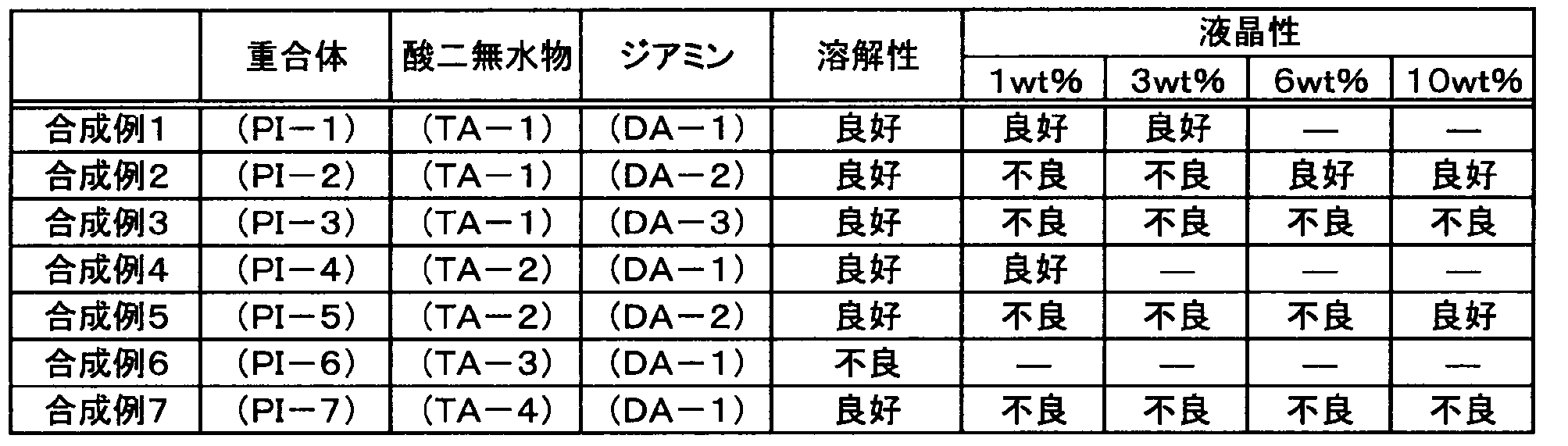
[実施例1]
(1)組成物の調製
合成例1で得た重合体(PI-1)を水に溶解させ、強酸性陽イオン交換樹脂を通してイオン交換することにより、対カチオンがEt3NH+からH+に交換された酸性重合体(以下、「酸性重合体(PI-1A」という。)の水溶液を得た。得られた水溶液を再生セルロース製の透析用チューブ (カットオフ分子量3500、Spectra/Por社製)を用いて蒸留水に対して室温で透析することによりさらに精製を行った。透析後の水溶液を減圧下で濃縮した後、酸性重合体(PI-1A)の酸性官能基に対して1モル当量の塩基性モノマー(M-1)を加え、次いで重合開始剤(I-1)を加えて溶解させた。得られた水溶液を孔径0.45μmのフィルターで濾過することにより、酸性重合体(PI-1A)及び塩基性モノマーの合計の固形分濃度が3質量%、重合開始剤の固形分濃度が0.05質量%である組成物(C-1)を調製した。図9に、酸性重合体(PI-1A)の1H-NMRスペクトル(DMSO-d6,700MHz)の測定結果を示す。
(1)組成物の調製
合成例1で得た重合体(PI-1)を水に溶解させ、強酸性陽イオン交換樹脂を通してイオン交換することにより、対カチオンがEt3NH+からH+に交換された酸性重合体(以下、「酸性重合体(PI-1A」という。)の水溶液を得た。得られた水溶液を再生セルロース製の透析用チューブ (カットオフ分子量3500、Spectra/Por社製)を用いて蒸留水に対して室温で透析することによりさらに精製を行った。透析後の水溶液を減圧下で濃縮した後、酸性重合体(PI-1A)の酸性官能基に対して1モル当量の塩基性モノマー(M-1)を加え、次いで重合開始剤(I-1)を加えて溶解させた。得られた水溶液を孔径0.45μmのフィルターで濾過することにより、酸性重合体(PI-1A)及び塩基性モノマーの合計の固形分濃度が3質量%、重合開始剤の固形分濃度が0.05質量%である組成物(C-1)を調製した。図9に、酸性重合体(PI-1A)の1H-NMRスペクトル(DMSO-d6,700MHz)の測定結果を示す。
(2)液晶配向膜の形成
透明電極を備えた透明基板の電極形成面に対して、上記(1)で調製した組成物(C-1)を50℃に加温した後、バーコーターを用いて10cm/sのせん断速度で塗布した。次いで、この基板を50℃の温風で5分間乾燥した後、庫内を窒素置換した100℃のオーブン中で30分間加熱した。これにより、平均膜厚0.1μmの液晶配向膜を基板上に形成した。この操作を繰り返し、透明電極上に液晶配向膜を有する一対の基板を得た。
(3)TN型液晶表示素子の製造
上記(2)で形成した基板の液晶配向膜形成面に対して、シール材として直径5.5μmの酸化アルミニウム球入りエポキシ樹脂接着剤を基板面の周縁部に沿うように塗布した。その後、一対の基板を液晶配向膜形成面が相対するように重ね合わせて圧着し、接着剤を硬化させた。次いで、液晶注入口より一対の基板間にネマチック液晶(MLC-6221、メルク社製)を充填した後、アクリル系光硬化接着剤で液晶注入口を封止した。さらに、液晶注入時の流動配向を除くために、これを120℃で加熱してから室温まで徐冷した。次に、基板の外側両面に偏光板を貼り合わせてTN型液晶表示素子を製造した。
透明電極を備えた透明基板の電極形成面に対して、上記(1)で調製した組成物(C-1)を50℃に加温した後、バーコーターを用いて10cm/sのせん断速度で塗布した。次いで、この基板を50℃の温風で5分間乾燥した後、庫内を窒素置換した100℃のオーブン中で30分間加熱した。これにより、平均膜厚0.1μmの液晶配向膜を基板上に形成した。この操作を繰り返し、透明電極上に液晶配向膜を有する一対の基板を得た。
(3)TN型液晶表示素子の製造
上記(2)で形成した基板の液晶配向膜形成面に対して、シール材として直径5.5μmの酸化アルミニウム球入りエポキシ樹脂接着剤を基板面の周縁部に沿うように塗布した。その後、一対の基板を液晶配向膜形成面が相対するように重ね合わせて圧着し、接着剤を硬化させた。次いで、液晶注入口より一対の基板間にネマチック液晶(MLC-6221、メルク社製)を充填した後、アクリル系光硬化接着剤で液晶注入口を封止した。さらに、液晶注入時の流動配向を除くために、これを120℃で加熱してから室温まで徐冷した。次に、基板の外側両面に偏光板を貼り合わせてTN型液晶表示素子を製造した。
(4)液晶配向性の評価
上記(3)で製造した液晶表示素子に5Vの電圧を印加及び解除し、明暗の変化における異常ドメインの有無を顕微鏡(倍率50倍)によって観察することにより液晶表示素子の液晶配向性を評価した。液晶配向性の評価は、異常ドメインが観察されなかった場合を「良好」とし、異常ドメインが観察された場合を「不良」とした。その結果、この実施例では「良好」の評価であった。
(5)電圧保持率の評価
上記(3)で製造した液晶表示素子に5Vの電圧を167ミリ秒の間隔で60マイクロ秒印加し、印加解除から167ミリ秒後の電圧保持率(VHR)を測定した。なお、測定装置は(株)東陽テクニカ製「VHR-1」を使用した。電圧保持率の評価は、VHRが80%以上であった場合を「良好」とし、VHRが80%未満であった場合を「不良」とした。その結果、この実施例では「良好」の評価であった。
上記(3)で製造した液晶表示素子に5Vの電圧を印加及び解除し、明暗の変化における異常ドメインの有無を顕微鏡(倍率50倍)によって観察することにより液晶表示素子の液晶配向性を評価した。液晶配向性の評価は、異常ドメインが観察されなかった場合を「良好」とし、異常ドメインが観察された場合を「不良」とした。その結果、この実施例では「良好」の評価であった。
(5)電圧保持率の評価
上記(3)で製造した液晶表示素子に5Vの電圧を167ミリ秒の間隔で60マイクロ秒印加し、印加解除から167ミリ秒後の電圧保持率(VHR)を測定した。なお、測定装置は(株)東陽テクニカ製「VHR-1」を使用した。電圧保持率の評価は、VHRが80%以上であった場合を「良好」とし、VHRが80%未満であった場合を「不良」とした。その結果、この実施例では「良好」の評価であった。
[実施例2及び比較例1]
上記実施例1において、組成物に含有させる重合体を下記表2に記載の通りに変更し、酸性重合体及び塩基性モノマーの合計の固形分濃度を6質量%に変更した以外は実施例1と同様にして、組成物(C-2、C-7)を調製した。また、得られた組成物をそれぞれ用いて液晶配向膜を形成し、液晶表示素子を製造するとともに、液晶配向性及び電圧保持率の評価を行った。評価結果を下記表2に示した。
[実施例3]
上記実施例1において、組成物に含有させる重合体を下記表2に記載の通りに変更し、酸性重合体及び塩基性モノマーの合計の固形分濃度を2質量%に変更した以外は実施例1と同様にして、組成物(C-3)を調製して液晶配向膜を形成し、液晶表示素子を製造するとともに、液晶配向性及び電圧保持率の評価を行った。評価結果を下記表2に示した。
[比較例2]
上記実施例1において、組成物の調製方法を下記(1A)の通りに変更した以外は実施例1と同様にして液晶配向膜を形成し、液晶表示素子を製造するとともに、液晶配向性及び電圧保持率の評価を行った。評価結果を下記表2に示した。
(1A)組成物の調製
合成例1で得た重合体(PI-1)を水に溶解させた。得られた水溶液を孔径0.45μmのフィルターで濾過することにより、重合体の固形分濃度が3質量%である組成物(C-8)を調製した。
上記実施例1において、組成物に含有させる重合体を下記表2に記載の通りに変更し、酸性重合体及び塩基性モノマーの合計の固形分濃度を6質量%に変更した以外は実施例1と同様にして、組成物(C-2、C-7)を調製した。また、得られた組成物をそれぞれ用いて液晶配向膜を形成し、液晶表示素子を製造するとともに、液晶配向性及び電圧保持率の評価を行った。評価結果を下記表2に示した。
[実施例3]
上記実施例1において、組成物に含有させる重合体を下記表2に記載の通りに変更し、酸性重合体及び塩基性モノマーの合計の固形分濃度を2質量%に変更した以外は実施例1と同様にして、組成物(C-3)を調製して液晶配向膜を形成し、液晶表示素子を製造するとともに、液晶配向性及び電圧保持率の評価を行った。評価結果を下記表2に示した。
[比較例2]
上記実施例1において、組成物の調製方法を下記(1A)の通りに変更した以外は実施例1と同様にして液晶配向膜を形成し、液晶表示素子を製造するとともに、液晶配向性及び電圧保持率の評価を行った。評価結果を下記表2に示した。
(1A)組成物の調製
合成例1で得た重合体(PI-1)を水に溶解させた。得られた水溶液を孔径0.45μmのフィルターで濾過することにより、重合体の固形分濃度が3質量%である組成物(C-8)を調製した。
[実施例4]
上記実施例1において、重合開始剤(I-1)に代えて重合開始剤(I-2)を使用した以外は実施例1と同様にして組成物(C-4)を調製した。また、調製した組成物(C-4)を用いて液晶配向膜を下記(2B)に記載の方法により形成した以外は実施例1と同様にして、液晶表示素子を製造するとともに、液晶配向性及び電圧保持率の評価を行った。評価結果を下記表2に示した。
(2B)液晶配向膜の形成
透明電極を備えた透明基板の電極形成面に対して組成物(C-4)を50℃に加温した後、バーコーターを用いて10cm/sのせん断速度で塗布した。次いで、この基板に対して高圧水銀ランプを用いて365nmの輝線を含む紫外線1,000mJ/cm2を基板法線方向から窒素雰囲気下で照射した後、50℃の温風で5分間乾燥し、さらに庫内を窒素置換した100℃のオーブン中で30分間加熱した。これにより、平均膜厚0.1μmの液晶配向膜を基板上に形成した。この操作を繰り返し、透明電極上に液晶配向膜を有する一対の基板を得た。
上記実施例1において、重合開始剤(I-1)に代えて重合開始剤(I-2)を使用した以外は実施例1と同様にして組成物(C-4)を調製した。また、調製した組成物(C-4)を用いて液晶配向膜を下記(2B)に記載の方法により形成した以外は実施例1と同様にして、液晶表示素子を製造するとともに、液晶配向性及び電圧保持率の評価を行った。評価結果を下記表2に示した。
(2B)液晶配向膜の形成
透明電極を備えた透明基板の電極形成面に対して組成物(C-4)を50℃に加温した後、バーコーターを用いて10cm/sのせん断速度で塗布した。次いで、この基板に対して高圧水銀ランプを用いて365nmの輝線を含む紫外線1,000mJ/cm2を基板法線方向から窒素雰囲気下で照射した後、50℃の温風で5分間乾燥し、さらに庫内を窒素置換した100℃のオーブン中で30分間加熱した。これにより、平均膜厚0.1μmの液晶配向膜を基板上に形成した。この操作を繰り返し、透明電極上に液晶配向膜を有する一対の基板を得た。
[実施例5]
上記実施例1において、組成物の調製及び液晶配向膜の形成をそれぞれ下記(1C)及び(2C)の通りに変更した以外は実施例1と同様にして、液晶表示素子を製造するとともに、液晶配向性及び電圧保持率の評価を行った。評価結果を下記表2に示した。
(1C)組成物の調製
合成例1で得た重合体(PI-1)を水に溶解させて水溶液を得た。得られた水溶液に、重合体(PI-1)の酸性官能基に対して0.5モル当量の熱塩基発生剤(A-1)を加えて溶解させた。この水溶液を孔径0.45μmのフィルターで濾過することにより、重合体と熱塩基発生剤の合計の固形分濃度が3質量%である組成物(C-5)を調製した。
(2C)液晶配向膜の形成
透明電極を備えた透明基板の電極形成面に対して、上記(1C)で調製した組成物(C-5)を50℃に加温して室温のゲル相から液晶相に相転移させた後、バーコーターを用いて10cm/sの速度で塗布した。次いで、この基板を50℃の温風で5分間乾燥した後、庫内を窒素置換した230℃のオーブン中で30分間加熱した。これにより、平均膜厚0.1μmの液晶配向膜を基板上に形成した。この操作を繰り返し、透明電極上に液晶配向膜を有する一対の基板を得た。
上記実施例1において、組成物の調製及び液晶配向膜の形成をそれぞれ下記(1C)及び(2C)の通りに変更した以外は実施例1と同様にして、液晶表示素子を製造するとともに、液晶配向性及び電圧保持率の評価を行った。評価結果を下記表2に示した。
(1C)組成物の調製
合成例1で得た重合体(PI-1)を水に溶解させて水溶液を得た。得られた水溶液に、重合体(PI-1)の酸性官能基に対して0.5モル当量の熱塩基発生剤(A-1)を加えて溶解させた。この水溶液を孔径0.45μmのフィルターで濾過することにより、重合体と熱塩基発生剤の合計の固形分濃度が3質量%である組成物(C-5)を調製した。
(2C)液晶配向膜の形成
透明電極を備えた透明基板の電極形成面に対して、上記(1C)で調製した組成物(C-5)を50℃に加温して室温のゲル相から液晶相に相転移させた後、バーコーターを用いて10cm/sの速度で塗布した。次いで、この基板を50℃の温風で5分間乾燥した後、庫内を窒素置換した230℃のオーブン中で30分間加熱した。これにより、平均膜厚0.1μmの液晶配向膜を基板上に形成した。この操作を繰り返し、透明電極上に液晶配向膜を有する一対の基板を得た。
[実施例6]
上記実施例4において、熱塩基発生剤(A-1)に代えて熱塩基発生剤(A-2)を使用した以外は実施例4と同様にして組成物(C-6)を調製した。また、得られた組成物(C-6)を用いて液晶配向膜を形成し、液晶表示素子を製造するとともに、液晶配向性及び電圧保持率の評価を行った。評価結果を下記表2に示した。
上記実施例4において、熱塩基発生剤(A-1)に代えて熱塩基発生剤(A-2)を使用した以外は実施例4と同様にして組成物(C-6)を調製した。また、得られた組成物(C-6)を用いて液晶配向膜を形成し、液晶表示素子を製造するとともに、液晶配向性及び電圧保持率の評価を行った。評価結果を下記表2に示した。
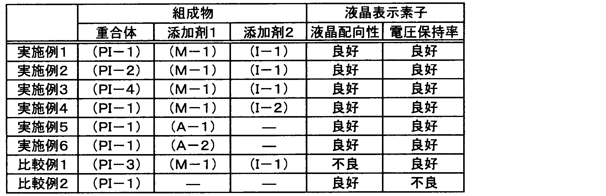
表2に示すように、実施例1~6の組成物を用いて液晶配向膜を形成することにより、液晶配向性及び電圧保持率が共に良好な液晶表示素子が得られることが分かった。一方、リオトロピック液晶性を示さない比較例1の組成物を用いた場合には、液晶配向性が「不良」の評価であった。また、化合物(A)を含まない比較例2の組成物を用いた場合には、電圧保持率が低かった。
[実施例7]
(1)位相差膜の製造
TACフィルム基材に対して、実施例1で調製した組成物(C-1)を50℃に加温した後、バーコーターを用いて10cm/sのせん断速度で塗布した。次いで、この基板を50℃の温風で5分間乾燥した後、庫内を窒素置換した100℃のオーブン中で30分間加熱した。これにより、平均膜厚0.1μmの液晶配向膜を基板上に形成した。次いで、重合性液晶(RMS03?013C、メルク社製)を孔径0.45μmのフィルターでろ過した後、この重合性液晶を液晶配向膜上にバーコーターを用いて塗布して塗膜を形成した。この塗膜を50℃の温風で1分間乾燥した後、基板に対し、高圧水銀ランプを用いて、365nmの輝線を含む紫外線1,000mJ/cm2を基板法線方向から照射した。これにより、重合性液晶が硬化した液晶層を有する位相差膜を製造した。
(2)液晶配向性の評価
上記(1)で製造した位相差膜を用いて、位相差膜の液晶配向性を評価した。上記位相差膜において直交ニコル下での異常ドメインの有無を偏光顕微鏡(倍率2.5倍)によって観察した。液晶配向性の評価は、異常ドメインが観察されなかった場合を「良好」とし、異常ドメインが観察された場合を「不良」とした。その結果、この実施例では「良好」の評価であった。
(1)位相差膜の製造
TACフィルム基材に対して、実施例1で調製した組成物(C-1)を50℃に加温した後、バーコーターを用いて10cm/sのせん断速度で塗布した。次いで、この基板を50℃の温風で5分間乾燥した後、庫内を窒素置換した100℃のオーブン中で30分間加熱した。これにより、平均膜厚0.1μmの液晶配向膜を基板上に形成した。次いで、重合性液晶(RMS03?013C、メルク社製)を孔径0.45μmのフィルターでろ過した後、この重合性液晶を液晶配向膜上にバーコーターを用いて塗布して塗膜を形成した。この塗膜を50℃の温風で1分間乾燥した後、基板に対し、高圧水銀ランプを用いて、365nmの輝線を含む紫外線1,000mJ/cm2を基板法線方向から照射した。これにより、重合性液晶が硬化した液晶層を有する位相差膜を製造した。
(2)液晶配向性の評価
上記(1)で製造した位相差膜を用いて、位相差膜の液晶配向性を評価した。上記位相差膜において直交ニコル下での異常ドメインの有無を偏光顕微鏡(倍率2.5倍)によって観察した。液晶配向性の評価は、異常ドメインが観察されなかった場合を「良好」とし、異常ドメインが観察された場合を「不良」とした。その結果、この実施例では「良好」の評価であった。
[実施例8]
(1)組成物の調製
合成例1で得た重合体(PI-1)を水に溶解させ、強酸性陽イオン交換樹脂を通してイオン交換することにより、対カチオンがEt3NH+からH+に交換された酸性重合体の水溶液を得た。この水溶液に、酸性重合体の酸性官能基に対して1モル当量の塩基性モノマー(M-1)を加え、次いで重合開始剤(I-1)を加えて溶解させ、さらに水溶性の二色性色素であるビープリッヒスカーレットを加えて溶解させた。得られた水溶液を孔径0.45μmのフィルターで濾過することにより、酸性重合体及び塩基性モノマーの合計の固形分濃度が3質量%、重合開始剤の固形分濃度が0.1質量%、二色性色素の固形分濃度が6質量%である組成物(C-9)を調製した。
(2)偏光膜の製造
ガラス基板に対して、上記(1)で調製した組成物(C-9)を50℃に加温した後、バーコーターを用いて10cm/sのせん断速度で塗布した。次いで、この基板を50℃の温風で5分間乾燥した後、庫内を窒素置換した100℃のオーブン中で30分間加熱した。これにより、平均膜厚3μmの偏光膜を基板上に形成した。
(3)偏光特性の評価
偏光膜の単体透過率(T)及び偏光度(P)により偏光膜の偏光特性を評価した。まず、グランテーラープリズム偏光子を装着した分光光度計(V-670、日本分光(株)製)を用いて、偏光膜の吸収軸方位及び透過軸方位の透過率をそれぞれ測定した。検光子の偏光度は100%であると仮定した。透過率の測定値を用いて、下記数式(b)により単体透過率(T)を求めた。単体透過率(T)の評価は、得られた偏光膜の単体透過率(T)が25%以上を「良好」、25%未満を「不良」とした。
T[%]=(Tp+Tc)/2×100 …(b)
また、透過率の測定値を用いて、下記数式(c)により偏光度(P)を求めた。偏光度(P)の評価は、偏光膜の偏光度(P)が50%以上を「良好」、50%未満を「不良」とした。
P[%]={(Tp-Tc)/(Tp+Tc)}0.5×100 …(c)
なお、上記数式(b)及び(c)中、Tpは試料の透過軸方位の透過率であり、Tcは試料の吸収軸方位の透過率である。その結果、この実施例では、単体透過率(T)及び偏光度(P)はいずれも「良好」の評価であった。
(1)組成物の調製
合成例1で得た重合体(PI-1)を水に溶解させ、強酸性陽イオン交換樹脂を通してイオン交換することにより、対カチオンがEt3NH+からH+に交換された酸性重合体の水溶液を得た。この水溶液に、酸性重合体の酸性官能基に対して1モル当量の塩基性モノマー(M-1)を加え、次いで重合開始剤(I-1)を加えて溶解させ、さらに水溶性の二色性色素であるビープリッヒスカーレットを加えて溶解させた。得られた水溶液を孔径0.45μmのフィルターで濾過することにより、酸性重合体及び塩基性モノマーの合計の固形分濃度が3質量%、重合開始剤の固形分濃度が0.1質量%、二色性色素の固形分濃度が6質量%である組成物(C-9)を調製した。
(2)偏光膜の製造
ガラス基板に対して、上記(1)で調製した組成物(C-9)を50℃に加温した後、バーコーターを用いて10cm/sのせん断速度で塗布した。次いで、この基板を50℃の温風で5分間乾燥した後、庫内を窒素置換した100℃のオーブン中で30分間加熱した。これにより、平均膜厚3μmの偏光膜を基板上に形成した。
(3)偏光特性の評価
偏光膜の単体透過率(T)及び偏光度(P)により偏光膜の偏光特性を評価した。まず、グランテーラープリズム偏光子を装着した分光光度計(V-670、日本分光(株)製)を用いて、偏光膜の吸収軸方位及び透過軸方位の透過率をそれぞれ測定した。検光子の偏光度は100%であると仮定した。透過率の測定値を用いて、下記数式(b)により単体透過率(T)を求めた。単体透過率(T)の評価は、得られた偏光膜の単体透過率(T)が25%以上を「良好」、25%未満を「不良」とした。
T[%]=(Tp+Tc)/2×100 …(b)
また、透過率の測定値を用いて、下記数式(c)により偏光度(P)を求めた。偏光度(P)の評価は、偏光膜の偏光度(P)が50%以上を「良好」、50%未満を「不良」とした。
P[%]={(Tp-Tc)/(Tp+Tc)}0.5×100 …(c)
なお、上記数式(b)及び(c)中、Tpは試料の透過軸方位の透過率であり、Tcは試料の吸収軸方位の透過率である。その結果、この実施例では、単体透過率(T)及び偏光度(P)はいずれも「良好」の評価であった。
[実施例9]
(1)液晶組成物の調製
下記式(LC-1)で表される化合物をLiq. Cryst., 2000, 27 (2), 283-287に記載の方法に従って製造した。また、下記式(LC-2)で表される化合物を国際公開第2011/066905号に記載の方法に従って製造した。次いで、下記式(LC-1)で表される化合物0.95g、及び下記式(LC-2)で表される化合物0.05gを混合し、液晶組成物Qを得た。

(1)液晶組成物の調製
下記式(LC-1)で表される化合物をLiq. Cryst., 2000, 27 (2), 283-287に記載の方法に従って製造した。また、下記式(LC-2)で表される化合物を国際公開第2011/066905号に記載の方法に従って製造した。次いで、下記式(LC-1)で表される化合物0.95g、及び下記式(LC-2)で表される化合物0.05gを混合し、液晶組成物Qを得た。
(2)液晶配向膜の形成
図4及び図5に示すパッチ基板12及びスロット基板13のそれぞれの電極形成面に対して、実施例1で調製した組成物(C-1)を50℃に加温して室温のゲル相から液晶相に相転移させた後、バーコーターを用いて10cm/sの速度で塗布した。次いで、これらの基板を50℃の温風で5分間乾燥した後、庫内を窒素置換した120℃のオーブン中で30分間加熱した。これにより、平均膜厚0.5μmの液晶配向膜を各基板上に形成した。
(3)アレイアンテナの製造
図4及び図5に示す液晶アンテナ10を製造した。液晶層14については上記(1)で調製した液晶組成物Qを用いて形成し、液晶配向膜(第1配向膜22、第2配向膜23)については、組成物(C-1)を用いて上記(2)と同様にして形成した。
(4)誘電正接の評価
キーコム社製摂動式空間共振装置を用いて、温度25℃、周波数30GHzの条件下での誘電正接(tanδ)を測定した。測定は、上記(3)で製造したアレイアンテナを共振装置及びベクトルネットワークアナライザを介してパーソナルコンピュータに接続し、測定周波数30GHz、測定環境温度25℃で行った。共振装置に試料を挿入した場合と、挿入していない場合とにおける共振周波数とQ値との差により誘電正接の値を求めた。評価は、tanδが0.0030未満であった場合を「良好」、0.0030以上であった場合を「不良」とした。その結果、この実施例では「良好」の評価であった。この結果から、重合体(P)、水及び化合物(A)を含有する組成物を用いて液晶配向膜を形成することにより、誘電損失が小さい液晶アンテナを得ることができることが分かった。
図4及び図5に示すパッチ基板12及びスロット基板13のそれぞれの電極形成面に対して、実施例1で調製した組成物(C-1)を50℃に加温して室温のゲル相から液晶相に相転移させた後、バーコーターを用いて10cm/sの速度で塗布した。次いで、これらの基板を50℃の温風で5分間乾燥した後、庫内を窒素置換した120℃のオーブン中で30分間加熱した。これにより、平均膜厚0.5μmの液晶配向膜を各基板上に形成した。
(3)アレイアンテナの製造
図4及び図5に示す液晶アンテナ10を製造した。液晶層14については上記(1)で調製した液晶組成物Qを用いて形成し、液晶配向膜(第1配向膜22、第2配向膜23)については、組成物(C-1)を用いて上記(2)と同様にして形成した。
(4)誘電正接の評価
キーコム社製摂動式空間共振装置を用いて、温度25℃、周波数30GHzの条件下での誘電正接(tanδ)を測定した。測定は、上記(3)で製造したアレイアンテナを共振装置及びベクトルネットワークアナライザを介してパーソナルコンピュータに接続し、測定周波数30GHz、測定環境温度25℃で行った。共振装置に試料を挿入した場合と、挿入していない場合とにおける共振周波数とQ値との差により誘電正接の値を求めた。評価は、tanδが0.0030未満であった場合を「良好」、0.0030以上であった場合を「不良」とした。その結果、この実施例では「良好」の評価であった。この結果から、重合体(P)、水及び化合物(A)を含有する組成物を用いて液晶配向膜を形成することにより、誘電損失が小さい液晶アンテナを得ることができることが分かった。
10…アレイアンテナ、11…アンテナ単位、14…液晶層、16…パッチ電極、19…スロット電極、22…第1配向膜、23…第2配向膜、100…位相差板、200…偏光板、300…液晶表示装置
Claims (15)
- 酸性官能基を有する重合体(P)と、
水と、
塩基性モノマー及び塩基発生剤よりなる群から選ばれる少なくとも一種である化合物(A)と、
を含有する、リオトロピック液晶性を示す組成物。 - 前記化合物(A)として前記塩基性モノマーを少なくとも含み、
重合開始剤を更に含有する、請求項1に記載の組成物。 - 前記塩基発生剤は、保護されていてもよい塩基性官能基を複数個有する多官能性化合物である、請求項1又は2に記載の組成物。
- 前記重合体(P)は、下記式(0)で表される部分構造を有する重合体である、請求項1~3のいずれか一項に記載の組成物。

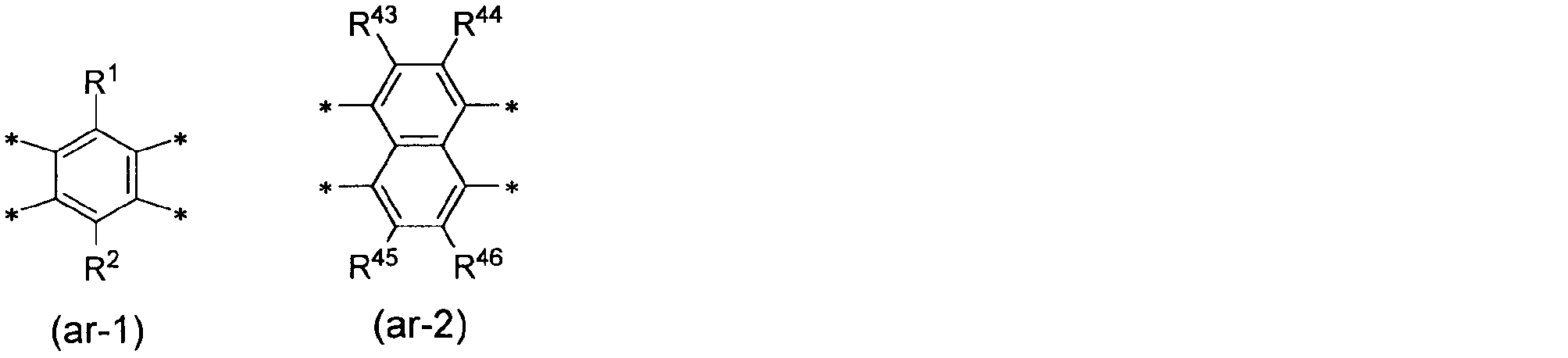
- 下記式(0)で表される部分構造を有する重合体(P)と、
水と、
塩基性モノマー及び塩基発生剤よりなる群から選ばれる少なくとも一種である化合物(A)と、
を含有する、組成物。


- 前記重合体(P)は、下記式(1)で表される部分構造を有する重合体である、請求項1~5のいずれか一項に記載の組成物。

- 二色性色素、色素会合体、量子ロッド、金属ナノロッド及びカーボンナノチューブよりなる群から選ばれる少なくとも一種を更に含有する、請求項1~6のいずれか一項に記載の組成物。
- 酸性官能基を有する重合体(P)と、
水と、
塩基性モノマー及び塩基発生剤よりなる群から選ばれる少なくとも一種である化合物(A)と、
を含有する、リオトロピック液晶性を示す液晶配向剤。 - 請求項1~7のいずれか一項に記載の組成物を液晶相の状態で基材上に塗布し、前記重合体(P)を配向させた状態で乾燥する工程を含む、有機膜の製造方法。
- 請求項1~7のいずれか一項に記載の組成物において感光性化合物を含有する組成物を液晶相の状態で基材上に塗布し、前記重合体(P)を配向させた状態で乾燥することにより液晶配向膜を形成する工程と、
前記液晶配向膜の一部を露光する工程と、
前記露光された液晶配向膜を現像する工程と、
を含む、パターン化液晶配向膜の製造方法。 - 請求項1~7のいずれか一項に記載の組成物を用いて形成された液晶配向膜。
- 請求項1~7のいずれか一項に記載の組成物を用いて形成された偏光板。
- 請求項11に記載の液晶配向膜を備える位相差板。
- 複数のアンテナ単位を有するアレイ型の液晶アンテナであって、
請求項11に記載の液晶配向膜を備える、液晶アンテナ。 - 請求項11に記載の液晶配向膜を備える液晶素子。
Priority Applications (3)
| Application Number | Priority Date | Filing Date | Title |
|---|---|---|---|
| CN201980070787.XA CN112912446A (zh) | 2018-12-10 | 2019-10-10 | 组合物及其用途 |
| JP2020559759A JP7298625B2 (ja) | 2018-12-10 | 2019-10-10 | 組成物及びその利用 |
| US17/325,202 US20210277185A1 (en) | 2018-12-10 | 2021-05-19 | Composition and use thereof |
Applications Claiming Priority (2)
| Application Number | Priority Date | Filing Date | Title |
|---|---|---|---|
| JP2018-230868 | 2018-12-10 | ||
| JP2018230868 | 2018-12-10 |
Related Child Applications (1)
| Application Number | Title | Priority Date | Filing Date |
|---|---|---|---|
| US17/325,202 Continuation US20210277185A1 (en) | 2018-12-10 | 2021-05-19 | Composition and use thereof |
Publications (1)
| Publication Number | Publication Date |
|---|---|
| WO2020121641A1 true WO2020121641A1 (ja) | 2020-06-18 |
Family
ID=71077193
Family Applications (1)
| Application Number | Title | Priority Date | Filing Date |
|---|---|---|---|
| PCT/JP2019/040132 Ceased WO2020121641A1 (ja) | 2018-12-10 | 2019-10-10 | 組成物及びその利用 |
Country Status (5)
| Country | Link |
|---|---|
| US (1) | US20210277185A1 (ja) |
| JP (1) | JP7298625B2 (ja) |
| CN (1) | CN112912446A (ja) |
| TW (1) | TWI816933B (ja) |
| WO (1) | WO2020121641A1 (ja) |
Cited By (1)
| Publication number | Priority date | Publication date | Assignee | Title |
|---|---|---|---|---|
| WO2024203918A1 (ja) * | 2023-03-29 | 2024-10-03 | 富士フイルム株式会社 | 樹脂組成物、再配線層用層間絶縁膜の製造方法、及び樹脂 |
Families Citing this family (2)
| Publication number | Priority date | Publication date | Assignee | Title |
|---|---|---|---|---|
| TWI827926B (zh) * | 2021-05-06 | 2024-01-01 | 友達光電股份有限公司 | 射頻液晶天線系統 |
| CN117008238A (zh) * | 2022-04-28 | 2023-11-07 | 北京字跳网络技术有限公司 | 光学偏振器件及其制造方法、近眼显示设备 |
Citations (9)
| Publication number | Priority date | Publication date | Assignee | Title |
|---|---|---|---|---|
| JP2007513358A (ja) * | 2003-09-23 | 2007-05-24 | 日東電工株式会社 | 二相フィルム材料および製造方法 |
| JP2012042886A (ja) * | 2010-08-23 | 2012-03-01 | Sekisui Chem Co Ltd | 光学補償積層フィルム、複合偏光板、偏光板及び液晶表示装置 |
| US20150266999A1 (en) * | 2014-03-18 | 2015-09-24 | Light Polymers B.V. | Insolubilization of water-soluble polyaramide by cross-linking with polyfunctional aziridine |
| JP2015200831A (ja) * | 2014-04-09 | 2015-11-12 | 富士フイルム株式会社 | 輝度向上膜、偏光板、および画像表示装置 |
| US20160266292A1 (en) * | 2015-03-13 | 2016-09-15 | Light Polymers Holding | Coatable Polymer Polarizer |
| US20170044398A1 (en) * | 2014-04-26 | 2017-02-16 | Mary Parent | Colloids containing polyaramide |
| WO2017130489A1 (ja) * | 2016-01-29 | 2017-08-03 | シャープ株式会社 | 走査アンテナ |
| WO2017150971A1 (en) * | 2016-02-29 | 2017-09-08 | Stichting Katholieke Universiteit | Cells and layered structures comprising polyimide alignment layers and based on liquid crystal solutions of lyotropic chromonic liquid crystals and surface active agents and methods of their manufacture |
| WO2018230222A1 (ja) * | 2017-06-12 | 2018-12-20 | Jsr株式会社 | 組成物、液晶配向膜、位相差板、偏光板、配向膜の製造方法及び液晶素子 |
Family Cites Families (5)
| Publication number | Priority date | Publication date | Assignee | Title |
|---|---|---|---|---|
| EP2373761B1 (en) * | 2008-12-04 | 2013-08-21 | Crysoptix K.K. | Organic polymer compound, optical film and method of production thereof |
| KR101985215B1 (ko) * | 2015-05-29 | 2019-06-03 | 후지필름 가부시키가이샤 | 폴리이미드 전구체 조성물, 감광성 수지 조성물, 경화막, 경화막의 제조 방법, 반도체 디바이스 및 폴리이미드 전구체 조성물의 제조 방법 |
| JP2019197078A (ja) * | 2016-09-20 | 2019-11-14 | 日産化学株式会社 | 液晶配向剤、液晶配向膜及び液晶表示素子 |
| CN111171842A (zh) * | 2017-02-28 | 2020-05-19 | Jsr株式会社 | 液晶取向剂、液晶取向膜、液晶元件及聚合体 |
| JP7163582B2 (ja) * | 2018-01-25 | 2022-11-01 | 富士フイルムビジネスイノベーション株式会社 | ポリイミド前駆体溶液、成形体、及び、成形体の製造方法 |
-
2019
- 2019-10-10 CN CN201980070787.XA patent/CN112912446A/zh active Pending
- 2019-10-10 JP JP2020559759A patent/JP7298625B2/ja active Active
- 2019-10-10 WO PCT/JP2019/040132 patent/WO2020121641A1/ja not_active Ceased
- 2019-11-12 TW TW108140922A patent/TWI816933B/zh active
-
2021
- 2021-05-19 US US17/325,202 patent/US20210277185A1/en not_active Abandoned
Patent Citations (9)
| Publication number | Priority date | Publication date | Assignee | Title |
|---|---|---|---|---|
| JP2007513358A (ja) * | 2003-09-23 | 2007-05-24 | 日東電工株式会社 | 二相フィルム材料および製造方法 |
| JP2012042886A (ja) * | 2010-08-23 | 2012-03-01 | Sekisui Chem Co Ltd | 光学補償積層フィルム、複合偏光板、偏光板及び液晶表示装置 |
| US20150266999A1 (en) * | 2014-03-18 | 2015-09-24 | Light Polymers B.V. | Insolubilization of water-soluble polyaramide by cross-linking with polyfunctional aziridine |
| JP2015200831A (ja) * | 2014-04-09 | 2015-11-12 | 富士フイルム株式会社 | 輝度向上膜、偏光板、および画像表示装置 |
| US20170044398A1 (en) * | 2014-04-26 | 2017-02-16 | Mary Parent | Colloids containing polyaramide |
| US20160266292A1 (en) * | 2015-03-13 | 2016-09-15 | Light Polymers Holding | Coatable Polymer Polarizer |
| WO2017130489A1 (ja) * | 2016-01-29 | 2017-08-03 | シャープ株式会社 | 走査アンテナ |
| WO2017150971A1 (en) * | 2016-02-29 | 2017-09-08 | Stichting Katholieke Universiteit | Cells and layered structures comprising polyimide alignment layers and based on liquid crystal solutions of lyotropic chromonic liquid crystals and surface active agents and methods of their manufacture |
| WO2018230222A1 (ja) * | 2017-06-12 | 2018-12-20 | Jsr株式会社 | 組成物、液晶配向膜、位相差板、偏光板、配向膜の製造方法及び液晶素子 |
Cited By (1)
| Publication number | Priority date | Publication date | Assignee | Title |
|---|---|---|---|---|
| WO2024203918A1 (ja) * | 2023-03-29 | 2024-10-03 | 富士フイルム株式会社 | 樹脂組成物、再配線層用層間絶縁膜の製造方法、及び樹脂 |
Also Published As
| Publication number | Publication date |
|---|---|
| TW202022044A (zh) | 2020-06-16 |
| US20210277185A1 (en) | 2021-09-09 |
| TWI816933B (zh) | 2023-10-01 |
| CN112912446A (zh) | 2021-06-04 |
| JP7298625B2 (ja) | 2023-06-27 |
| JPWO2020121641A1 (ja) | 2021-11-04 |
Similar Documents
| Publication | Publication Date | Title |
|---|---|---|
| CN104845642B (zh) | 液晶取向剂、液晶取向膜、液晶显示元件、相位差膜及其制造方法、聚合物以及化合物 | |
| TWI761521B (zh) | 顯示出溶致液晶性的組成物、聚醯亞胺聚合物、液晶配向劑、液晶配向膜及其製造方法、相位差板、偏光板及液晶元件 | |
| TWI627262B (zh) | 液晶配向層、其製備方法及包括其之液晶顯示裝置 | |
| JP6375789B2 (ja) | 液晶配向剤、液晶配向膜、液晶表示素子、位相差フィルム及びその製造方法 | |
| WO2013041017A1 (zh) | 预聚物、取向膜及其制备方法、液晶显示装置 | |
| US20210277185A1 (en) | Composition and use thereof | |
| CN105190416B (zh) | 液晶取向剂、使用其得到的液晶表示元件及其制造方法 | |
| CN104109538B (zh) | 液晶取向剂、液晶取向膜、液晶显示元件、相位差膜及其制造方法、聚合物以及化合物 | |
| KR102663141B1 (ko) | 막 형성용 조성물, 경화막, 액정 배향막 및 위상차 필름 | |
| CN102108300A (zh) | 液晶取向剂、液晶取向膜和液晶显示元件 | |
| CN102193250B (zh) | 液晶显示元件的制造方法、聚合物组合物和液晶显示元件 | |
| CN112055832B (zh) | 液晶取向剂及其制造方法、液晶取向膜及其制造方法以及液晶元件 | |
| TWI793298B (zh) | 液晶配向劑及聚合物 | |
| CN113260911A (zh) | 液晶取向剂、液晶取向膜及液晶元件 | |
| CN110235055B (zh) | 液晶取向膜和使用其的液晶显示装置 | |
| TWI791731B (zh) | 液晶配向劑、液晶配向膜、液晶元件及其製造方法 | |
| CN108885375B (zh) | 液晶取向膜、用于制备其的方法和使用其的液晶显示装置 | |
| TWI814748B (zh) | 液晶配向劑、液晶配向膜、液晶元件及液晶配向膜的製造方法 | |
| KR20120085515A (ko) | 액정 배향제, 이를 이용하여 제조한 액정 배향막 및 상기 액정 배향막을 포함하는 액정표시소자 | |
| TW202216850A (zh) | 光配向用液晶配向劑、液晶配向膜、液晶元件及液晶配向膜的製造方法 | |
| WO2020121640A1 (ja) | 偏光膜の製造方法、光学素子及び液晶素子 | |
| JP7159755B2 (ja) | 液晶配向剤、液晶配向膜、光学フィルム及び液晶素子 | |
| CN115717079A (zh) | 液晶取向剂、液晶取向膜、液晶显示元件及液晶取向膜的制造方法 | |
| CN116891752A (zh) | 液晶取向剂、液晶取向膜及其制造方法、及液晶元件 |
Legal Events
| Date | Code | Title | Description |
|---|---|---|---|
| 121 | Ep: the epo has been informed by wipo that ep was designated in this application |
Ref document number: 19895814 Country of ref document: EP Kind code of ref document: A1 |
|
| ENP | Entry into the national phase |
Ref document number: 2020559759 Country of ref document: JP Kind code of ref document: A |
|
| NENP | Non-entry into the national phase |
Ref country code: DE |
|
| 122 | Ep: pct application non-entry in european phase |
Ref document number: 19895814 Country of ref document: EP Kind code of ref document: A1 |