WO2020121611A1 - 試験システムの軸トルク制御器及びフィードバック制御器の設計方法、並びにこの設計方法に基づいて設計される軸トルク制御器 - Google Patents
試験システムの軸トルク制御器及びフィードバック制御器の設計方法、並びにこの設計方法に基づいて設計される軸トルク制御器 Download PDFInfo
- Publication number
- WO2020121611A1 WO2020121611A1 PCT/JP2019/035712 JP2019035712W WO2020121611A1 WO 2020121611 A1 WO2020121611 A1 WO 2020121611A1 JP 2019035712 W JP2019035712 W JP 2019035712W WO 2020121611 A1 WO2020121611 A1 WO 2020121611A1
- Authority
- WO
- WIPO (PCT)
- Prior art keywords
- output
- input
- controller
- shaft torque
- plant
- Prior art date
- Legal status (The legal status is an assumption and is not a legal conclusion. Google has not performed a legal analysis and makes no representation as to the accuracy of the status listed.)
- Ceased
Links
Images



Classifications
-
- G—PHYSICS
- G01—MEASURING; TESTING
- G01M—TESTING STATIC OR DYNAMIC BALANCE OF MACHINES OR STRUCTURES; TESTING OF STRUCTURES OR APPARATUS, NOT OTHERWISE PROVIDED FOR
- G01M13/00—Testing of machine parts
- G01M13/02—Gearings; Transmission mechanisms
- G01M13/025—Test-benches with rotational drive means and loading means; Load or drive simulation
Definitions
- the present invention relates to a method of designing a shaft torque controller and a feedback controller of a test system, and a shaft torque controller designed by this design method. More specifically, the present invention relates to a design method for designing a shaft torque controller and a feedback controller based on a generalized plant, and a shaft torque controller designed by this design method.
- ⁇ Drive train is a general term for a plurality of devices for transmitting energy generated in the engine to the drive wheels, and is composed of an engine, a clutch, a transmission, a drive shaft, a propeller shaft, a differential gear, a drive wheel, and the like.
- the transmission is actually driven by the engine and the output side dynamometer connected to the output shaft is electrically inertially controlled, so that the load torque that simulates the inertia of the tire or vehicle body is output to the output shaft. While giving, the durability and quality of the drive train are evaluated.
- a dynamometer is connected to the input shaft of the drive train, and the dynamometer is driven by using the shaft torque controller, so that the drive torque input to the input shaft of the drive train is changed to the actual engine.
- a dynamometer is also proposed.
- a technique of designing a shaft torque controller used in a test system by a controller design method based on a generalized plant such as a ⁇ design method or H ⁇ control has been proposed (for example, see Non-Patent Document 1). ).
- the generalized plant has a command value and this command value.
- a control amount output port is set that outputs a value obtained by weighting the deviation from the signal to be tracked with a weighting function having an integral characteristic (see, for example, the weighting function Ws in Non-Patent Document 1).
- the gain of the integrator included in the controller designed based on such a generalized plant is equal to the gain of the weighting function defined in the generalized plant. Does not match. In other words, the conventional controller design method based on the generalized plant cannot specify the value of the integral gain of the finally obtained controller at the design stage.
- the response performance of the controller is almost determined by the value of the integral gain. Therefore, in some cases, it is required to be able to specify the value of the integral gain of the controller finally obtained in the controller designing method at the design stage.
- Patent Document 1 by the applicant of the present application discloses an electric inertia control device configured by combining an existing shaft torque controller and a low-pass filter.
- the control device it is necessary to tune the values of a plurality of control parameters (a1, a2, b1, etc.) that characterize the low-pass filter using the value of the integral gain of the shaft torque controller. Therefore, even when designing a shaft torque controller incorporated in such an electric inertia control device by a controller design method based on a generalized plant, the value of the integral gain of the shaft torque controller finally obtained is set at the design stage. It is required to be able to specify.
- the present invention is a design method of a shaft torque controller or a general feedback controller of a test system designed based on a generalized plant, and a design method capable of bringing an integral gain of these controllers close to a specified value. It is also an object of the present invention to provide a shaft torque controller designed by using this design method.
- a dynamometer for example, an input side dynamometer 21 described below
- a shaft for example, an input shaft SI described below
- a sample for example, a test sample W described below
- an inverter that supplies electric power according to the torque current command signal to the dynamometer (for example, an input-side inverter 23 described later), and a shaft torque detection signal according to the shaft torque between the dynamometer and the DUT.
- a test system (for example, a test system 1 described later) including a shaft torque detector (for example, an input side shaft torque meter 25 described later) that generates
- the present invention relates to a method of designing a shaft torque controller (for example, a shaft torque controller 5 described later) that generates the torque current command signal so as to suppress a deviation from a torque detection signal.
- the shaft torque controller calculates a first input by integrating a deviation between the shaft torque command signal and the shaft torque detection signal and multiplying the integrated gain by a specified value (for example, an integration gain Ki described later).
- An integrator for example, an integrator 52 described below
- a non-integrator for example, a non-integrator 53 described below
- a torque current command generator for example, a torque current command generator 54 described later
- the designing method is a generalized plant (for example, a general plant described later) including a nominal plant (for example, a nominal plant N described later) that imitates an input/output characteristic from the torque current command signal of the control target to the shaft torque detection signal.
- Generalized plant P and a controller (for example, a ⁇ controller K described later) that gives an input to the generalized plant based on the output of the generalized plant, a feedback control system (for example, a feedback control system described later).
- a mounting step for example, S3 of FIG. 6 described later.
- a first disturbance input port for example, a later-described first disturbance input w1 corresponding to the shaft torque command signal is input to the generalized plant.
- the integral operation amount calculation unit calculates the integral operation amount by multiplying by the integral gain of the specified value (for example, by inputting an integral manipulated variable calculation unit 90) described below and the output of the nominal plant to the controller, the output obtained by the controller and the integral manipulated variable are summed, and input to the nominal plant.
- a summing unit for example, a summing unit 91 to be described later
- a product obtained by multiplying the deviation input by a predetermined first output weighting function for example, a first output weighting function Ge(s) to be described later
- a first controlled variable output port (for example, a first controlled variable output port 84 described later) that outputs as a variable output (for example, a first controlled variable output z1 described later), and a predetermined second output weight for the output of the controller.
- a second control amount output port (for example, a second control amount output port (for example, a second control amount output z2 described below)) that is multiplied by a function (for example, a second output weighting function Gip(s) described below) is output.
- a second controlled variable output port 85 described later.
- the first and second output weighting functions have integral characteristics.
- the second disturbance input (for example, a second disturbance input w2 described later) corresponding to the torque control error of the dynamometer is input to the generalized plant as the second disturbance.
- An input port (for example, a second disturbance input port 82 described later) is further set, and the output of the controller, the integral operation amount, and the second disturbance input having a predetermined second input weight with respect to the nominal plant. It is preferable to input the sum of a function (for example, a product obtained by multiplying a second input weighting function Gid(s) described later).
- a third disturbance input (for example, a third disturbance input w3 described later) corresponding to a torque detection error by the shaft torque detector is input to the generalized plant.
- Three disturbance input ports (for example, a third disturbance input port 83 described later) are further set, and a predetermined first input weighting function for the first disturbance input (for example, a first disturbance described below
- An output of the nominal plant and the third disturbance input are multiplied by a predetermined third input weighting function (for example, a third input weighting function Gn(s) described later) from a product of the input weighting function Gr(s)). It is preferable to input a value obtained by subtracting the sum of the calculated value and the calculated value.
- the output of the nominal plant is multiplied by a predetermined third output weighting function (for example, a third output weighting function Gt(s) described later) with respect to the generalized plant.
- a third controlled variable output for example, a third controlled variable output z3 described below
- a third controlled variable output port for example, a third controlled variable output port 86 described later
- the function is set to have a larger weight in a frequency band including the torsional resonance frequency between the dynamometer and the sample than in other frequency bands.
- the design method according to the present invention integrates a deviation between a control output of a control target (for example, a test system 1 described later) and a command for the control output, and integrates a specified value of an integral gain (for example, an integration gain described later). Ki) and an integrator (for example, integrator 52 described later) that calculates the first input, and a non-integrator (for example, non-integrator 53 described later) that calculates the second input based on the control output. ) And a control input generator (for example, a torque current command generator 54 described later) that generates the control input based on the first and second inputs and inputs the control input to the controlled object ().
- Ki an integrator
- a non-integrator for example, non-integrator 53 described later
- the design method includes a generalized plant (for example, a generalized plant P described later) including a nominal plant (for example, a nominal plant N described later) that imitates an input/output characteristic from the control input to the control output of the control target. And a controller that gives an input to the generalized plant based on the output of the generalized plant (for example, a ⁇ controller K described later), the control that satisfies a predetermined design condition.
- a computer for example, S1 and S2 in FIG. 6 described later
- mounting process for mounting the controller as the non-integrator in the feedback controller for example, S3 in FIG.
- a first disturbance input port for example, a first disturbance input described later to which a first disturbance input (for example, a first disturbance input w1 described later) corresponding to the command is input to the generalized plant.
- Port 81 and a deviation input between the first disturbance input and the output of the nominal plant, and an integral operation amount calculation unit (for example, which will be described later) that calculates an integral operation amount by multiplying by an integral gain of the specified value.
- a summation unit for example, a summation unit 91 described later
- a product obtained by multiplying the deviation input by a predetermined first output weighting function for example, a first output weighting function Ge(s) described later
- a predetermined first output weighting function for example, a first output weighting function Ge(s) described later
- a first control amount output for example, a first controlled variable output port (for example, a first controlled variable output port 84 described later) that outputs as a first controlled variable output z1 described later, and a predetermined second output weighting function (for example, a first controlled variable output port 84 described later) for the output of the controller.
- a second control amount output port (for example, a later-described second control amount output Z2) that outputs a product of a later-described second output weighting function Gip(s) as a second control amount output (for example, a later-described second control amount output z2). 2 control amount output port 85).
- a shaft torque controller (for example, a shaft torque controller 5 described later) according to the present invention is connected to a shaft (for example, an input shaft SI described below) of a sample (for example, a sample W described below).
- a dynamometer for example, an input side dynamometer 21 described later
- an inverter for example, an input side inverter 23 described later
- a test system for example, a test system 1 described later including a shaft torque detector (for example, an input side shaft torque meter 25 described later) that generates a shaft torque detection signal according to a shaft torque between Then, the torque current command signal is generated so as to suppress the deviation between the shaft torque command signal and the shaft torque detection signal with respect to the shaft torque.
- the shaft torque controller calculates a first input by integrating a deviation between the shaft torque command signal and the shaft torque detection signal and multiplying the integrated gain by a specified value (for example, an integration gain Ki described later).
- An integrator for example, an integrator 52 described below
- a non-integrator for example, a non-integrator 53 described below
- the first and the first The torque current command signal is generated by summing two inputs
- the non-integrator is a nominal plant (for example, a model of the input/output characteristics from the torque current command signal of the control target to the shaft torque detection signal).
- a generalized plant for example, a generalized plant P described later
- a controller for example, a ⁇ controller described later described
- the generalized plant has a first disturbance input port (for example, a first disturbance input port 81 described later) to which a first disturbance input (for example, a first disturbance input w1 described later) corresponding to the shaft torque command signal is input.
- a first disturbance input for example, a first disturbance input w1 described later
- an integral manipulated variable calculating unit that calculates an integral manipulated variable by integrating the deviation input between the first disturbance input and the output of the nominal plant and multiplying it by the integral gain of the specified value (for example, the integral manipulation described later).
- Quantity calculation unit 90 and a summing unit that sums the output obtained by the controller by inputting the output of the nominal plant to the controller and the integral manipulated variable, and generates the input to the nominal plant.
- a summing unit 91 described later and a product obtained by multiplying the deviation input by a predetermined first output weighting function are output as a first control amount output (for example, later described).
- a first controlled variable output port e.g., a first controlled variable output port 84 described below
- a second output weighting function e.g., a later described later
- a second control amount output port (for example, a second control amount described below) that outputs a product of the second output weighting function Gip(s)) as a second control amount output (for example, a second control amount output z2 described below).
- Output port 85 (for example, a second control amount described below) that outputs a product of the second output weighting function Gip(s)) as a second control amount output (for example, a second control amount output z2 described below).
- the present invention relates to a method for designing a shaft torque controller for a test system including a dynamometer, an inverter, and a shaft torque detector.
- This shaft torque controller integrates the deviation between the shaft torque command signal and the shaft torque detection signal, and further multiplies the integral gain of a predetermined specified value to calculate the first input, and the shaft torque detection signal.
- a non-integrator that calculates a second input based on the first input and a torque current command generator that generates a torque current command signal based on the first and second inputs are provided.
- a design for designing a controller that satisfies a predetermined design condition by a computer is designed through a process and a mounting process in which the controller obtained through the design process is mounted on the shaft torque controller as a non-integrator.
- the shaft torque controller includes the integrator that performs the integration operation under the integral gain of the specified value.
- the integrator and the non-integrator are designed.
- the integral gain of the integral element in the entire shaft torque controller which is set to, deviates from the specified value. Therefore, in the design method of the present invention, the first disturbance input port to which the first disturbance input corresponding to the shaft torque command signal is input, and the deviation input between the first disturbance input and the output of the nominal plant are input to the generalized plant.
- the integral manipulated variable calculator that integrates and multiplies the integral gain by the specified value to calculate the integral manipulated variable, and the output and integral manipulated variable obtained by this controller by inputting the output of the nominal plant to the controller.
- a summing unit that generates an input to the nominal plant, a first control amount output port that outputs a product obtained by multiplying the deviation input by a predetermined first output weighting function as a first control amount output, and a controller. And a second controlled variable output port for outputting a product of the output of ##EQU1## multiplied by a predetermined second output weighting function as a second controlled variable output.
- the first output weighting function for multiplying the deviation input to the integral manipulated variable calculating unit (corresponding to the integrator in the shaft torque controller) in the generalized plant, and the controller in generalization has an integral characteristic.
- the second disturbance input port to which the second disturbance input corresponding to the torque control error of the dynamometer is input is set for the generalized plant, and the controller for the nominal plant is set to the second disturbance input port.
- the sum of the output, the integrated operation amount, and the product of the second disturbance input and a predetermined second input weighting function is input.
- the third disturbance input port to which the third disturbance input corresponding to the torque detection error by the shaft torque detector is input is set in the generalized plant, and the integrated manipulated variable calculating unit is set. Inputs the sum of the output of the nominal plant and the third disturbance input multiplied by the third input weighting function from the first disturbance input multiplied by the first input weighting function.
- the third control amount output port for outputting the product of the output of the nominal plant multiplied by the third output weighting function as the third control amount output is set in the generalized plant.
- the third output weighting function is set so that the frequency band including the torsional resonance frequency between the dynamometer and the test piece has a greater weight than other frequency bands.
- the present invention is based on the integrator that calculates the first input by integrating the deviation between the control output of the controlled object and the command for this control output, and by multiplying the integral gain of the command value, and the control output.
- the present invention relates to a feedback controller design method including a non-integrator that calculates a second input and a control input generator that generates a control input based on the first and second inputs and inputs the control input to a control target.
- a design for designing a controller that satisfies a predetermined design condition by a computer is designed through the steps and the mounting step of mounting the controller obtained through the designing step on the feedback controller as a non-integrator.
- the feedback controller includes an integrator that performs an integral operation under an integral gain of a specified value, but if the non-integrator is designed by a design method based on the conventional generalized plant, the integrator and the non-integrator are The integrated gain of the integrated elements in the combined feedback controller may deviate from the specified value.
- the first disturbance input port to which the first disturbance input corresponding to the command is input, and the deviation input between the first disturbance input and the output of the nominal plant are integrated into the generalized plant,
- An integral manipulated variable calculating unit that calculates the integral manipulated variable by multiplying the integral gain of the specified value
- an integral manipulated variable calculator that calculates the integral manipulated variable by inputting the output of the nominal plant to the controller, and a nominal
- the output obtained by this integrator and the integral operation amount are summed up, and a summing unit for generating an input to the nominal plant, and a predetermined first output weighting function for the deviation input.
- a first controlled variable output port that outputs the multiplied one as a first controlled variable output, and a second controlled variable output that outputs the one obtained by multiplying the output of the controller by a predetermined second output weighting function as a second controlled variable output.
- the non-integrator does not include the integral element as much as possible by incorporating the integral operation amount calculation unit corresponding to the integrator of the Fordback controller in the generalized plant in the design stage in advance. Therefore, it is possible to bring the integral gain of the integral element in the entire feedback controller close to the specified value.
- the shaft torque controller of the test system of the present invention includes a non-integrator designed using the generalized plant according to the design method of (1) above. Therefore, according to the present invention, since the non-integrator can be made to contain the integral element as little as possible, the integral gain of the integral element in the entire shaft torque controller can be brought close to the specified value.
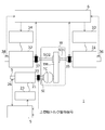
- FIG. 1 is a diagram showing a configuration of a drive train test system 1 including a shaft torque controller 5 according to the present embodiment.
- FIG. 1 shows an example of a test system 1 in which a drive train of a vehicle of the FF drive system is used as a sample W and the performance of the sample W is evaluated, but the present invention is not limited to this.
- the sample W may be, for example, a drive train of an FR drive type vehicle.
- the test piece W is a drive train for a vehicle, and when mounted on a completed vehicle, an input shaft SI to which an engine (not shown) is connected, left and right output shafts SO1 and SO2 that are drive shafts, and input to the input shaft SI are input.
- a torque converter TC that amplifies the generated power and transmits it to the output shafts SO1 and SO2, and a transmission TM that shifts the power input to the input shaft SI and transmits it to the output shafts SO1 and SO2.
- the test system 1 includes an input-side dynamometer 21, an input-side inverter 23, an input-side shaft torque meter 25, an input-side encoder 26, and a shaft torque controller 5, which are provided on the input shaft SI side of the sample W, and a sample.
- the tip side of the output shaft S of the input side dynamometer 21 is connected to the input shaft SI of the sample W.
- the input side inverter 23 supplies the input side dynamometer 21 with electric power according to the input side torque current command signal.
- the input side dynamometer 21 generates torque according to the input side torque current command signal.
- the input side shaft torque meter 25 generates an input side shaft torque detection signal corresponding to the shaft torque between the output shaft S of the input side dynamometer 21 and the input shaft SI of the sample W, and sends it to the shaft torque controller 5.
- the input side encoder 26 detects the rotation speed (the number of rotations of the shaft per unit time) of the output shaft S of the input side dynamometer 21, generates an input side speed detection signal corresponding to this rotation speed, and controls the shaft torque. Input to the container 5.
- the shaft torque controller 5 is based on an input side shaft torque detection signal from the input side shaft torque meter 25 and an upper shaft torque command signal corresponding to a command signal for the shaft torque detected by the input side shaft torque meter 25. This is a feedback controller that generates an input side torque current command signal and inputs this input side torque current command signal to the input side inverter 23.
- the upper axis torque command signal is generated in an upper controller (not shown) according to the contents of the test on the sample W.
- the shaft torque controller 5 causes the input-side dynamometer 21 to generate a drive torque simulating the engine of the completed vehicle in which the test piece W is mounted, and drives the input shaft SI of the test piece W.
- the shaft torque controller 5 controls the input side torque current command signal so as to suppress the shaft torque deviation (upper side shaft torque command signal-input side shaft torque detection signal) between the higher order shaft torque command signal and the input side shaft torque detection signal. It has at least both functions of a shaft torque deviation suppressing function to be generated and a resonance suppressing function of suppressing torsional resonance between the output shaft S and the input shaft SI.
- a shaft torque controller 5 designed according to a procedure described later with reference to FIGS. 2 to 6 is used.
- the output shaft of the first output-side dynamometer 31 is connected to the output shaft SO1 of the sample W.
- the first output-side inverter 33 supplies power corresponding to the first output-side torque current command signal to the first output-side dynamo. Supply to the meter 31.
- the first output-side dynamometer 31 generates torque according to the first output-side torque current command signal.
- the first output-side shaft torque meter 35 generates a first output-side shaft torque detection signal corresponding to the shaft torque between the output shaft of the first output-side dynamometer 31 and the output shaft SO1 of the sample W, and outputs it. Input to the side controller 6.
- the first output-side encoder 36 detects the rotation speed of the output shaft of the first output-side dynamometer 31, generates a first output-side speed detection signal corresponding to this rotation speed, and inputs it to the output-side control device 6. ..
- the output shaft of the dynamometer 32 on the second output side is connected to the output shaft SO2 of the sample W.
- the second output side torque current command signal generated by the output side control device 6 is input to the second output side inverter 34, the second output side dynamo outputs electric power corresponding to the second output side torque current command signal.
- Supply to the meter 32 As a result, the second output side dynamometer 32 generates torque according to the second output side torque current command signal.
- the second output-side shaft torque meter 37 generates a second output-side shaft torque detection signal corresponding to the shaft torque between the output shaft of the second output-side dynamometer 32 and the output shaft SO2 of the sample W, and outputs it. Input to the side controller 6.
- the second output side encoder 38 detects the rotation speed of the output shaft of the second output side dynamometer 32, generates a second output side speed detection signal corresponding to this rotation speed, and inputs it to the output side control device 6. ..
- the output-side control device 6 uses the first output-side shaft torque meter 35 to output a first output-side shaft torque detection signal, the first output-side encoder 36 to output a first speed-side detection signal, and the second output-side shaft torque meter 37 to output a first output-side speed torque signal.
- the input signal such as the second output side torque detection signal and the second output side speed detection signal from the second output side encoder 38
- the first output side torque current command signal and the second output side torque current command signal are generated. It is generated and these are input to the first output side inverter 33 and the second output side inverter 34.
- the output-side control device 6 determines the load simulating the tire inertia and the vehicle body inertia in the completed vehicle in which the test piece W is mounted and the load applied to the test piece W on the first output side dynamometer 31 and the second output side. It is applied to the output shafts SO1 and SO2 via the dynamometer 32.
- the shaft torque controller 5 drives the input shaft SI of the test piece W, and at the same time, the output side control device 6 applies a load to the output shafts SO1 and SO2 of the test piece W to simulate the tire inertia and the vehicle body inertia, and the like.
- the durability performance, quality, etc. of the sample W are evaluated under a state close to the running state of the actual vehicle.
- the shaft torque controller 5 having the shaft torque deviation suppressing function and the resonance suppressing function as described above will be described with reference to the drawings.
- the configuration of the test system 1 on the side of the input shaft SI of the sample W will be described. Therefore, the input side dynamometer 21 is simply referred to as the dynamometer 21, and the input side inverter 23 is simply referred to as the inverter 23.
- the input side shaft torque meter 25 is simply referred to as the shaft torque meter 25
- the input side shaft torque detection signal is simply referred to as the shaft torque detection signal
- the input side encoder 26 is simply referred to as the encoder 26
- the input side speed detection signal is simply referred to as It is called a speed detection signal
- the input side torque current command signal is simply called a torque current command signal.
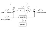
- FIG. 2 is a diagram showing a configuration of a control circuit of the shaft torque controller 5.
- the shaft torque controller 5 includes a deviation calculation unit 51 that calculates the deviation between the higher-order shaft torque command signal and the shaft torque detection signal, and an integrator 52 that calculates the first input based on the deviation calculated by the deviation calculation unit 51.
- a non-integrator 53 that calculates a second input based on the shaft torque detection signal, and a torque current command generator 54 that generates a torque current command signal based on the first and second inputs and inputs the torque current command signal to the inverter 23. , Is provided.
- the deviation calculation unit 51 calculates the deviation by subtracting the axis torque detection signal from the upper axis torque command signal.
- the integrator 52 includes an integration calculation unit 521 that integrates the deviation, and an integration gain multiplication unit 522 that calculates the first input by multiplying the output of the integration calculation 521 by the integration gain Ki of a specified value.
- the ⁇ controller K designed according to the procedure described later with reference to FIGS. 3 to 6 is used.
- the torque current command generator 54 generates a torque current command signal by adding the first input and the second input.
- the shaft torque controller 5 combines the deviation calculator 51, the integrator 52, the non-integrator 53, and the torque current command generator 54 having the above-described functions with a digital signal as shown in the circuit diagram of FIG. It is configured by being mounted on hardware including an input/output port such as a processor or a microcomputer.
- the shaft torque controller 5 in which the ⁇ controller K described later is mounted has a shaft torque command signal transmitted via communication from a host controller (not shown) and an axis torque command signal.
- a torque current command signal is generated and input to the inverter 23 via communication.
- the inverter 23 electrically connected to the dynamometer 21 causes the dynamometer 21 to generate a torque according to the torque current command signal.
- Disturbance factors assumed at this time include noise generated when measuring the shaft torque in the shaft torque meter 25, time delay in each communication path, torque current command signal due to control response of the inverter 23, and dynamometer.
- the above-described higher-level shaft torque command signal may be generated by a higher-level controller other than the shaft torque controller 5 as described above, or may be constructed inside the shaft torque controller 5 separately from the ⁇ controller K and the like. May be generated by the created module.
- FIG. 3 is a diagram showing a configuration of the feedback control system 8 used when designing the non-integrator 53 of the shaft torque controller 5.
- the feedback control system of FIG. 3 provides a generalized plant P having a nominal plant N imitating the input/output characteristics of the test system 1 and an input ⁇ to the generalized plant P based on the output of the generalized plant P. It is configured by combining the controller K and.
- the generalized plant P has an input composed of a first disturbance input w1, a second disturbance input w2, and a third disturbance input w3, a first controlled variable output z1, a second controlled variable output z2, and a third controlled variable.
- the output z3 and the output composed of the fourth controlled variable output z4 are defined.
- an observation output y corresponding to a shaft torque detection signal and a control input u corresponding to a torque current command signal are defined between the generalized plant P and the ⁇ controller K.
- FIG. 4 is a diagram showing a configuration of a generalized plant P used when designing the non-integrator 53.
- the generalized plant P has a first disturbance input port 81 to which the first disturbance input w1 is input, a second disturbance input port 82 to which the second disturbance input w2 is input, and a third disturbance input w3.
- Unit 91 simulating the input/output characteristics of the torque current command generator 54 of the controller 5, a subtractor 94 simulating the input/output characteristics of the deviation calculator 51 of the shaft torque controller 5, and a plurality of weighting functions Gid(s). ), Gr(s), Gn(s), Ge(s), Gip(s), Gir(s), Gt(s).
- the nominal plant N is an input/output characteristic that imitates a characteristic from a dynamometer torque i1 which is one of the inputs in the test system 1 described with reference to FIG. 1 to a transmission torque t1 which is one of the outputs in the test system 1. Equipped with.
- the dynamometer torque i1 corresponds to the torque generated in the dynamometer 21 based on the torque current command signal input to the inverter 23 in the test system 1.
- the transmission torque t1 corresponds to the torque transmitted from the output shaft S of the dynamometer 21 to the input shaft SI of the sample W in the test system 1, in other words, the shaft torque between the output shaft S and the input shaft SI.
- the transmission torque t1 is detected by the axial torque meter 25 in the test system 1.
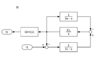
- FIG. 5 is a diagram showing a configuration of the nominal plant N.
- the nominal plant N has, for example, two inertial bodies configured by connecting two inertial bodies having a specimen inertia moment Jw and a dynamo inertia moment J1 in series with a shaft body having a torsional rigidity K1. It is constructed based on the equation of motion of the system (see the following equations (1-1) to (1-3)). In the present embodiment, in the test system 1, the case where the test piece torque input to the test piece W by the output side dynamometers 31, 32 via the output shafts SO1, SO2 is ignored will be described. Not limited to
- the specimen moment of inertia Jw corresponds to the moment of inertia of the specimen W in the test system 1.
- the dynamo inertia moment J1 corresponds to the inertia moment of the dynamo meter 21 in the test system 1.
- the torsional rigidity K1 corresponds to the torsional rigidity of the device that connects the sample W and the dynamometer 21 in the test system 1.
- the transfer function Gtm(s) corresponds to the response characteristic of the axial torque meter 25 in the test system 1.
- the nominal model N generates the transmission torque t1 based on the dynamo torque i1 by using the motion equations shown in FIG. 5 and the above equations (1-1) to (1-3).
- a fourth controlled variable output z4, a control input u, and an observation output y are defined. The correspondence between these input/output signals and the test system 1 of FIG. 1 is as follows.
- the second disturbance input w2 is an input signal input to the generalized plant P via the second disturbance input port 82.
- the second disturbance input w2 is a disturbance input corresponding to the torque control error (deviation between the torque current command signal and the dynamo torque i1) of the inverter 23 and the dynamometer 21 in the test system 1.
- the influence of the torque control error is evaluated by inputting such a second disturbance input w2 to the second disturbance input port 82.
- the signal obtained by summing the signal obtained by weighting the second disturbance input w2 by the second input weighting function Gid(s) and the output signal of the summing unit 91, which will be described later, is nominally the dynamo torque i1.
- the second input weighting function Gid(s) is set according to the frequency characteristic of the torque control error in the inverter 23 and the dynamometer 21. Since the control response of the inverter 23 has an upper limit, the torque control error has a characteristic of becoming large in the high frequency band. Therefore, the second input weighting function Gid(s) is set to have a larger weight in the high frequency band in which the torque control error tends to increase than in the low frequency band.
- the third disturbance input w3 is an input signal input to the generalized plant P via the third disturbance input port 83.
- the third disturbance input w3 is a disturbance input corresponding to a torque detection error (deviation between the shaft torque detection signal and the transmission torque t1) by the shaft torque meter 25 in the test system 1.
- the influence of the torque detection error is evaluated by inputting such a third disturbance input w3 to the third disturbance input port 83.
- the signal obtained by adding the signal obtained by weighting the third disturbance input w3 by the third input weighting function Gn(s) and the transfer torque t1 output from the nominal plant N is the observation output y. Is output from the observation output port 89.
- the third disturbance input w3 is set according to the frequency characteristic of the torque detection error by the shaft torque meter 25. More specifically, in the high frequency band in which the torque detection error tends to increase, the weight is set to be larger than in the low frequency band in which the torque detection error tends to decrease.
- the first disturbance input w1 is an input signal input to the generalized plant P via the first disturbance input port 81.
- the first disturbance input w1 is a disturbance input corresponding to the upper axis torque command signal in the test system 1.
- the influence of the upper shaft torque command signal is evaluated.
- the signal obtained by weighting the first disturbance input w1 by the first input weighting function Gr(s) is input to the subtraction unit 94 described later.
- the first input weighting function Gr(s) is set to a constant, for example.
- the observation output y is a signal output from the generalized plant P to the observation output port 89 and input to the ⁇ controller K, and the shaft torque input to the non-integrator 53 in the shaft torque controller 5 of the test system 1. It corresponds to the detection signal.
- the observation output y is calculated by adding the third disturbance input w3 weighted by the third input weighting function Gn(s) and the transmission torque t1 output from the nominal plant N as described above. It
- the control input u is a signal output from the ⁇ controller K and input to the generalized plant P via the control input port 88, and is output from the non-integrator 53 in the shaft torque detector 5 of the test system 1. It corresponds to the second input.
- the control input u input via the control input port 88 is input to the summing unit 91 described later.
- the subtraction unit 94 corresponds to the deviation calculation unit 51 in the shaft torque controller 5.
- the subtraction unit 94 calculates the deviation input by subtracting the observation output y from the signal obtained by weighting the first disturbance input w1 with the first input weighting function Gr(s), and inputs the deviation input to the integral operation amount calculation unit 90.
- the integral manipulated variable calculation unit 90 corresponds to the integrator 52 in the shaft torque controller 5.
- the integral operation amount calculation unit 90 integrates the deviation input calculated by the subtraction unit 94 and multiplies the integral operation amount Ki by the same specified value as the integral gain multiplication unit 522 of the shaft torque controller 5 to calculate the integral operation amount.
- the calculated value is input to the summing unit 91.
- the summing unit 91 corresponds to the torque current command generator 54 in the shaft torque controller 5.
- the summing unit 91 inputs the observation output y including the torque detection error to the ⁇ controller K as described above, and the control input u obtained by this ⁇ controller and the integral calculated by the integral operation amount calculating unit 90.
- An input signal to the nominal plant N is generated by adding the manipulated variable.
- the output signal of the summing unit 91 corresponds to the torque current command signal generated by the shaft torque controller 5 in the test system 1.
- the sum of the output signal of the summing unit 91 and the signal obtained by weighting the second disturbance input w2 with the second input weighting function Gid(s) is input to the nominal plant N as the dynamo torque i1.
- the first controlled variable output z1 is an output signal output from the generalized plant P via the first controlled variable output port 84.
- the first control amount output z1 corresponds to a deviation input (upper axis torque command signal-axis torque detection signal) input to the integrator 52 in the shaft torque controller 5.
- the first control amount output z1 is calculated by multiplying the deviation input input to the integral operation amount calculation unit 90 by the first output weighting function Ge(s).
- the deviation input to the integrator 52 can be evaluated by outputting such a first controlled variable output z1 from the first controlled variable output port 84.
- the first output weighting function Ge(s) is set to have an integral characteristic so that the shaft torque controller 5 having the shaft torque deviation suppressing function can be obtained.
- the second controlled variable output z2 is an output signal output from the generalized plant P via the second controlled variable output port 85.
- the second controlled variable output z2 corresponds to the second input output from the non-integrator 53 in the shaft torque controller 5.
- the second control amount output z2 is calculated by multiplying the control input u output from the ⁇ controller K by the second output weighting function Gip(s).
- the second input from the non-integrator 53 can be evaluated by outputting such a second controlled variable output z2 from the second controlled variable output port 85.
- This second output weighting function Gip(s) is set so that the integral gain of the integral element in the entire shaft torque controller 5 in which the ⁇ controller K is incorporated as the non-integrator 53 becomes equal to the integral gain Ki of the integrator 52. Are set to have integral characteristics.
- the third controlled variable output z3 is an output signal output from the generalized plant P via the third controlled variable output port 86.
- the third controlled variable output z3 corresponds to the transmission torque t1 in the test system 1.
- the third controlled variable output z3 is calculated by multiplying the transfer torque t1 output from the nominal plant N by the third output weighting function Gt(s).
- the transfer torque t1 can be evaluated by outputting such a third controlled variable output z3 from the third controlled variable output port 86.
- the third output weighting function Gt(s) is set based on the resonance characteristic in the device that connects the sample W and the dynamometer 21 so that the axial torque controller 5 having the resonance suppressing function can be obtained. More specifically, the third output weighting function Gt(s) is set to have a larger weight in the torsional resonance frequency band in the device that connects the sample W and the dynamometer 21 than in other frequency bands. It
- the fourth controlled variable output z4 is an output signal output from the generalized plant P via the fourth controlled variable output port 87.
- the fourth controlled variable output z4 corresponds to the torque current command signal output from the shaft torque controller 5 in the test system 1.
- the fourth controlled variable output z4 is calculated by multiplying the output signal of the summing unit 91 by the fourth output weighting function Gir(s).
- the torque current command signal of the shaft torque controller 5 can be evaluated by outputting such a fourth controlled variable output z4 from the fourth controlled variable output port 87.
- the fourth output weighting function Gir(s) is set to have a higher weight in the high frequency band than in the low frequency band, for example.
- FIG. 6 is a flowchart showing a procedure for designing the shaft torque controller 5 based on the generalized plant P.
- a computer is used so that a predetermined design condition determined to realize robust stability is satisfied.
- Design the ⁇ controller K More specifically, such a ⁇ controller K is derived by performing iterative calculation based on the DK iteration method on a computer, for example.
- the ⁇ controller K obtained in S2 is used as the non-integrator 53, and the deviation calculation unit 51, the integrator 52, the non-integrator 53, and the torque current command generation unit 54 in FIG.
- the shaft torque controller 5 is designed by mounting the combination as shown in the circuit diagram on the hardware having the input/output ports.
- the shaft torque controller of the comparative example is one designed based on the controller design method described in Non-Patent Document 1.
- a control amount output port for outputting the shaft torque deviation weighted by the weighting function having the integral characteristic was set in the generalized plant.
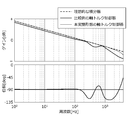
- FIG. 7 is a Bode diagram showing the characteristics of the torque current command signal with respect to the shaft torque deviation in each shaft torque controller.
- the thick line shows the characteristic of the shaft torque controller of the comparative example.
- the thick broken line shows the ideal integrator characteristics required for the shaft torque controller.
- the thin line is equal to the specified value of the integral gain Ki of the integrator 52 of FIG. 2 and the integral gain Ki of the generalized plant P of FIG.
- the designing method of the present embodiment by making the specified values of the integration gain Ki of the integrator 52 and the integration gain Ki of the generalized plant P equal to the value of the ideal integration gain of the integrator at the design stage, The finally obtained value of the integral gain of the shaft torque controller 5 can be brought close to the designated value set at the design stage. Therefore, as shown in FIG. 7, according to the designing method of the present embodiment, the value of the integral gain of the shaft torque controller 5 can be brought close to the value of the ideal integral gain of the integrator.
- the design method of the shaft torque controller according to the present invention is applied to the input side connected to the input shaft SI of the sample W in the drive train test system 1 in which the vehicle drive train is the sample W.
- the case where the invention is applied to the shaft torque controller 5 that controls the dynamometer 21 has been described, but the present invention is not limited to this.
- the method for designing the shaft torque controller according to the present invention includes, in the drive train test system 1, the first output-side dynamometer 31 connected to the output shaft SO1 of the sample W and the second output connected to the output shaft SO2. It may be applied to a shaft torque controller that controls the side dynamometer 32.
- the design method of the axial torque controller according to the present invention is applied to the axial torque controller whose control target is the drive train test system 1 in which the vehicle drive train is the specimen W.
- the present invention is not limited to this.
- the axial torque controller designing method according to the present invention may be applied to an axial torque controller whose control target is an engine test system (so-called engine bench system) in which a vehicle engine is used as a test object.
- a feedback controller design method according to the present invention is a feedback controller in which a control target generates a control output when a control input is input, and a control output of the control target and a command for the control output. And a non-integrator that calculates the second input based on the control output of the control target, and the first and the second It may be applied to a feedback controller including a control input generator that generates a control input based on two inputs and inputs the control input to a controlled object.
Landscapes
- Physics & Mathematics (AREA)
- General Physics & Mathematics (AREA)
- Testing Of Devices, Machine Parts, Or Other Structures Thereof (AREA)
Abstract
設計方法は、公称プラントNを備える一般化プラントP及びμ制御器Kを備えるフィードバック制御系において、所定の設計条件を満たすようなμ制御器Kをコンピュータによって設計する設計工程を備える。設計工程では、第1外乱入力ポート81と、第1外乱入力と公称プラントNの出力との偏差入力を積分し、指定値の積分ゲインKiを乗算することにより積分操作量を算出する積分操作量算出部90と、μ制御器Kの出力と積分操作量とを合算し公称プラントNへの入力を生成する合算部91と、偏差入力に第1出力重み関数Ge(s)を乗算したものを第1制御量出力z1として出力する第1制御量出力ポート84と、μ制御器Kの出力に第2出力重み関数Gip(s)を乗算したものを第2制御量出力z2として出力する第2制御量出力ポート85と、を設定する。
Description
本発明は、試験システムの軸トルク制御器及びフィードバック制御器の設計方法、並びにこの設計方法によって設計される軸トルク制御器に関する。より詳しくは、軸トルク制御器やフィードバック制御器を一般化プラントに基づいて設計する設計方法並びにこの設計方法によって設計される軸トルク制御器に関する。
ドライブトレインとは、エンジンで発生したエネルギーを駆動輪に伝達するための複数の装置の総称をいい、エンジン、クラッチ、トランスミッション、ドライブシャフト、プロペラシャフト、デファレンシャルギヤ、及び駆動輪等で構成される。ドライブトレインの試験システムでは、実際にエンジンでトランスミッションを駆動するとともに、その出力軸に接続された出力側ダイナモメータを電気慣性制御することにより、タイヤや車体の慣性を模した負荷トルクを出力軸に付与しながら、ドライブトレインの耐久性能や品質等が評価される。
またこのような試験システムでは、ドライブトレインの入力軸にダイナモメータを連結し、軸トルク制御器を用いてこのダイナモメータを駆動することにより、ドライブトレインの入力軸に入力する駆動トルクを、実エンジンの代わりにダイナモメータで発生させるものも提案されている。また近年では、試験システムに用いられる軸トルク制御器を、μ設計法やH∞制御等の一般化プラントに基づく制御器設計方法によって設計する技術も提案されている(例えば、非特許文献1参照)。
君嶋和之、西村秀和、「車両運動シミュレーション用エンジンベンチのロバスト制御」、日本機械学会論文集(C編)67巻653号(2001)
ところで、制御対象の制御出力をある指令値に追従させる制御器を、上述のような一般化プラントに基づく制御器設計方法によって設計する場合、一般化プラントには、指令値と、この指令値に追従させようとする信号との偏差を、積分特性を備える重み関数で重み付けしたものを出力する制御量出力ポートが設定される(例えば、非特許文献1における重み関数Ws参照)。しかしながら後に図7を参照して説明するように、このような一般化プラントに基づいて設計される制御器に含まれる積分器のゲインは、一般化プラントにおいて規定される重み関数のゲインと一般的には一致しない。換言すれば、一般化プラントに基づく従来の制御器設計方法では、最終的に得られる制御器の積分ゲインの値を設計段階で指定することはできない。
しかしながら制御器の応答性能は積分ゲインの値によってほぼ決定される。このため、上述のような制御器設計方法において最終的に得られる制御器の積分ゲインの値を設計段階で指定できるようにすることが求められる場合がある。
また例えば本願出願人による特許文献1には、既存の軸トルク制御器とローパスフィルタとを組み合わせることによって構成される電気慣性制御装置が示されているが、この特許文献1に示された電気慣性制御装置では、ローパスフィルタを特徴付ける複数の制御パラメータ(a1,a2,b1等)の値を、軸トルク制御器の積分ゲインの値を用いてチューニングする必要がある。従ってこのような電気慣性制御装置に組み込まれる軸トルク制御器を一般化プラントに基づく制御器設計方法で設計する場合にも、最終的に得られる軸トルク制御器の積分ゲインの値を設計段階で指定できるようにすることが求められる。
本発明は、一般化プラントに基づいて設計される試験システムの軸トルク制御器又は一般的なフィードバック制御器の設計方法であって、これら制御器の積分ゲインを指定値に近づけることができる設計方法、並びにこの設計方法を用いて設計される軸トルク制御器を提供することを目的とする。
(1)本発明に係る設計方法は、供試体(例えば、後述の供試体W)の軸(例えば、後述の入力軸SI)に連結されたダイナモメータ(例えば、後述の入力側ダイナモメータ21)と、トルク電流指令信号に応じた電力を前記ダイナモメータに供給するインバータ(例えば、後述の入力側インバータ23)と、前記ダイナモメータと前記供試体との間の軸トルクに応じた軸トルク検出信号を発生する軸トルク検出器(例えば、後述の入力側軸トルクメータ25)と、を備える試験システム(例えば、後述の試験システム1)を制御対象とし、前記軸トルクに対する軸トルク指令信号と前記軸トルク検出信号との偏差を抑制するように前記トルク電流指令信号を生成する軸トルク制御器(例えば、後述の軸トルク制御器5)を設計する方法に関する。前記軸トルク制御器は、前記軸トルク指令信号と前記軸トルク検出信号との偏差を積分し、指定値の積分ゲイン(例えば、後述の積分ゲインKi)を乗算することにより第1入力を算出する積分器(例えば、後述の積分器52)と、前記軸トルク検出信号に基づいて第2入力を算出する非積分器(例えば、後述の非積分器53)と、前記第1及び第2入力に基づいて前記トルク電流指令信号を生成し、前記インバータへ入力するトルク電流指令生成器(例えば、後述のトルク電流指令生成器54)と、を備える。前記設計方法は、前記制御対象の前記トルク電流指令信号から前記軸トルク検出信号までの入出力特性を模した公称プラント(例えば、後述の公称プラントN)を備える一般化プラント(例えば、後述の一般化プラントP)と、当該一般化プラントの出力に基づいて当該一般化プラントへ入力を与える制御器(例えば、後述のμ制御器K)と、を備えるフィードバック制御系(例えば、後述のフィードバック制御系8)において、所定の設計条件を満たすような前記制御器をコンピュータによって設計する設計工程(例えば、後述の図6のS1、S2)と、前記制御器を前記非積分器として前記軸トルク制御器に実装する実装工程(例えば、後述の図6のS3)と、を備える。前記設計工程では、前記一般化プラントに対し、前記軸トルク指令信号に相当する第1外乱入力(例えば、後述の第1外乱入力w1)が入力される第1外乱入力ポート(例えば、後述の第1外乱入力ポート81)と、前記第1外乱入力と前記公称プラントの出力との偏差入力を積分し、前記指定値の積分ゲインを乗算することにより積分操作量を算出する積分操作量算出部(例えば、後述の積分操作量算出部90)と、前記公称プラントの出力を前記制御器へ入力することにより当該制御器で得られる出力と前記積分操作量とを合算し、前記公称プラントへの入力を生成する合算部(例えば、後述の合算部91)と、前記偏差入力に所定の第1出力重み関数(例えば、後述の第1出力重み関数Ge(s))を乗算したものを第1制御量出力(例えば、後述の第1制御量出力z1)として出力する第1制御量出力ポート(例えば、後述の第1制御量出力ポート84)と、前記制御器の出力に所定の第2出力重み関数(例えば、後述の第2出力重み関数Gip(s))を乗算したものを第2制御量出力(例えば、後述の第2制御量出力z2)として出力する第2制御量出力ポート(例えば、後述の第2制御量出力ポート85)と、を設定する。
(2)この場合、前記第1及び第2出力重み関数は、積分特性を備えることが好ましい。
(3)この場合、前記設計工程では、前記一般化プラントに対し、前記ダイナモメータのトルク制御誤差に相当する第2外乱入力(例えば、後述の第2外乱入力w2)が入力される第2外乱入力ポート(例えば、後述の第2外乱入力ポート82)をさらに設定し、前記公称プラントに対し、前記制御器の出力と、前記積分操作量と、前記第2外乱入力に所定の第2入力重み関数(例えば、後述の第2入力重み関数Gid(s))を乗算したものと、の和を入力することが好ましい。
(4)この場合、前記設計工程では、前記一般化プラントに対し、前記軸トルク検出器によるトルク検出誤差に相当する第3外乱入力(例えば、後述の第3外乱入力w3)が入力される第3外乱入力ポート(例えば、後述の第3外乱入力ポート83)をさらに設定し、前記積分操作量算出部には、前記第1外乱入力に所定の第1入力重み関数(例えば、後述の第1入力重み関数Gr(s))を乗算したものから、前記公称プラントの出力と前記第3外乱入力に所定の第3入力重み関数(例えば、後述の第3入力重み関数Gn(s))を乗算したものとの和を減算したものを入力することが好ましい。
(5)この場合、前記設計工程では、前記一般化プラントに対し、前記公称プラントの出力に所定の第3出力重み関数(例えば、後述の第3出力重み関数Gt(s))を乗算したものを第3制御量出力(例えば、後述の第3制御量出力z3)として出力する第3制御量出力ポート(例えば、後述の第3制御量出力ポート86)をさらに設定し、前記第3出力重み関数を、前記ダイナモメータと前記供試体との間におけるねじり共振周波数を含む周波数帯域において他の周波数帯域よりも大きな重みになるように設定することが好ましい。
(6)本発明に係る設計方法は、制御対象(例えば、後述の試験システム1)の制御出力と当該制御出力に対する指令との偏差を積分し、指定値の積分ゲイン(例えば、後述の積分ゲインKi)を乗算することにより第1入力を算出する積分器(例えば、後述の積分器52)と、前記制御出力に基づいて第2入力を算出する非積分器(例えば、後述の非積分器53)と、前記第1及び第2入力に基づいて前記制御入力を生成し、前記制御対象に入力する制御入力生成器(例えば、後述のトルク電流指令生成器54)と、を備えるフィードバック制御器(例えば、後述の軸トルク制御器5)を設計する方法に関する。前記設計方法は、前記制御対象の前記制御入力から前記制御出力までの入出力特性を模した公称プラント(例えば、後述の公称プラントN)を備える一般化プラント(例えば、後述の一般化プラントP)と、当該一般化プラントの出力に基づいて当該一般化プラントへ入力を与える制御器(例えば、後述のμ制御器K)と、を備えるフィードバック制御系において、所定の設計条件を満たすような前記制御器をコンピュータによって設計する設計工程(例えば、後述の図6のS1、S2)と、前記制御器を前記非積分器として前記フィードバック制御器に実装する実装工程(例えば、後述の図6のS3)と、を備える。前記設計工程では、前記一般化プラントに対し、前記指令に相当する第1外乱入力(例えば、後述の第1外乱入力w1)が入力される第1外乱入力ポート(例えば、後述の第1外乱入力ポート81)と、前記第1外乱入力と前記公称プラントの出力との偏差入力を積分し、前記指定値の積分ゲインを乗算することにより積分操作量を算出する積分操作量算出部(例えば、後述の積分操作量算出部90)と、前記公称プラントの出力を前記制御器へ入力することにより当該制御器で得られる出力と前記積分操作量とを合算し、前記公称プラントへの入力を生成する合算部(例えば、後述の合算部91)と、前記偏差入力に所定の第1出力重み関数(例えば、後述の第1出力重み関数Ge(s))を乗算したものを第1制御量出力(例えば、後述の第1制御量出力z1)として出力する第1制御量出力ポート(例えば、後述の第1制御量出力ポート84)と、前記制御器の出力に所定の第2出力重み関数(例えば、後述の第2出力重み関数Gip(s))を乗算したものを第2制御量出力(例えば、後述の第2制御量出力z2)として出力する第2制御量出力ポート(例えば、後述の第2制御量出力ポート85)と、を設定することを特徴とする。
(7)本発明に係る軸トルク制御器(例えば、後述の軸トルク制御器5)は、供試体(例えば、後述の供試体W)の軸(例えば、後述の入力軸SI)に連結されたダイナモメータ(例えば、後述の入力側ダイナモメータ21)と、トルク電流指令信号に応じた電力を前記ダイナモメータに供給するインバータ(例えば、後述の入力側インバータ23)と、前記ダイナモメータと前記供試体との間の軸トルクに応じた軸トルク検出信号を発生する軸トルク検出器(例えば、後述の入力側軸トルクメータ25)と、を備える試験システム(例えば、後述の試験システム1)を制御対象とし、前記軸トルクに対する軸トルク指令信号と前記軸トルク検出信号との偏差を抑制するように前記トルク電流指令信号を生成する。前記軸トルク制御器は、前記軸トルク指令信号と前記軸トルク検出信号との偏差を積分し、指定値の積分ゲイン(例えば、後述の積分ゲインKi)を乗算することにより第1入力を算出する積分器(例えば、後述の積分器52)と、前記軸トルク検出信号に基づいて第2入力を算出する非積分器(例えば、後述の非積分器53)と、を備え、前記第1及び第2入力を合算することにより前記トルク電流指令信号を生成し、前記非積分器は、前記制御対象の前記トルク電流指令信号から前記軸トルク検出信号までの入出力特性を模した公称プラント(例えば、後述の公称プラントN)を備える一般化プラント(例えば、後述の一般化プラントP)と、当該一般化プラントの出力に基づいて当該一般化プラントへ入力を与える制御器(例えば、後述のμ制御器K)と、を備えるフィードバック制御系(例えば、後述のフィードバック制御系8)において、所定の設計条件を満たすようにコンピュータによって設計された前記制御器を備える。前記一般化プラントは、前記軸トルク指令信号に相当する第1外乱入力(例えば、後述の第1外乱入力w1)が入力される第1外乱入力ポート(例えば、後述の第1外乱入力ポート81)と、前記第1外乱入力と前記公称プラントの出力との偏差入力を積分し、前記指定値の積分ゲインを乗算することにより積分操作量を算出する積分操作量算出部(例えば、後述の積分操作量算出部90)と、前記公称プラントの出力を前記制御器へ入力することにより当該制御器で得られる出力と前記積分操作量とを合算し、前記公称プラントへの入力を生成する合算部(例えば、後述の合算部91)と、前記偏差入力に所定の第1出力重み関数(例えば、後述の第1出力重み関数Ge(s))を乗算したものを第1制御量出力(例えば、後述の第1制御量出力z1)として出力する第1制御量出力ポート(例えば、後述の第1制御量出力ポート84)と、前記制御器の出力に所定の第2出力重み関数(例えば、後述の第2出力重み関数Gip(s))を乗算したものを第2制御量出力(例えば、後述の第2制御量出力z2)として出力する第2制御量出力ポート(例えば、後述の第2制御量出力ポート85)と、を備える。
(1)本発明は、ダイナモメータ、インバータ、及び軸トルク検出器を備える試験システムを制御対象とした軸トルク制御器の設計方法に関する。この軸トルク制御器は、軸トルク指令信号と軸トルク検出信号の偏差を積分し、さらに所定の指定値の積分ゲインを乗算することにより第1入力を算出する積分器と、軸トルク検出信号に基づいて第2入力を算出する非積分器と、これら第1及び第2入力に基づいてトルク電流指令信号を生成するトルク電流指令生成器と、を備える。また本発明では、制御対象の入出力特性を模した公称プラントを備える一般化プラントと、制御器と、を備えるフィードバック制御系において、所定の設計条件を満たすような制御器をコンピュータによって設計する設計工程と、この設計工程を経て得られる制御器を非積分器として軸トルク制御器に実装する実装工程と、を経て軸トルク制御器を設計する。このように軸トルク制御器は、指定値の積分ゲインの下で積分演算を行う積分器を備えるが、非積分器を従来の一般化プラントに基づく設計方法によって設計すると、積分器及び非積分器を合せた軸トルク制御器全体における積分要素の積分ゲインは、上記指定値からずれてしまう場合がある。そこで本発明の設計方法では、一般化プラントに対し、軸トルク指令信号に相当する第1外乱入力が入力される第1外乱入力ポートと、第1外乱入力と公称プラントの出力との偏差入力を積分し、上記指定値の積分ゲインを乗算することにより積分操作量を算出する積分操作量算出部と、公称プラントの出力を制御器へ入力することによりこの制御器で得られる出力と積分操作量とを合算し、公称プラントへの入力を生成する合算部と、偏差入力に所定の第1出力重み関数を乗算したものを第1制御量出力として出力する第1制御量出力ポートと、制御器の出力に所定の第2出力重み関数を乗算したものを第2制御量出力として出力する第2制御量出力ポートと、を設定する。このように本発明では、設計段階で一般化プラントに軸トルク制御器の積分器に相当する積分操作量算出部を予め組み込んでおくことにより、非積分器には積分要素を極力含まないようにすることができるので、軸トルク制御器全体における積分要素の積分ゲインを指定値に近づけることができる。
(2)本発明の設計方法では、一般化プラントにおいて積分操作量算出部(軸トルク制御器における積分器に相当)への偏差入力に乗算する第1出力重み関数、及び一般化において制御器(軸トルク制御器における非積分器に相当)の出力に乗算する第2出力重み関数には、それぞれ積分特性を持たせる。これにより、本発明の設計方法を経て得られる軸トルク制御器全体における積分要素の積分ゲインを指定値に近づけることができる。
(3)本発明の設計方法では、一般化プラントに対し、ダイナモメータのトルク制御誤差に相当する第2外乱入力が入力される第2外乱入力ポートを設定し、公称プラントに対し、制御器の出力と、積分操作量と、上記第2外乱入力に所定の第2入力重み関数を乗算したものと、の和を入力する。これにより、積分要素の積分ゲインを指定値に近づけ、かつダイナモメータのトルク制御誤差に対しロバスト性の高い軸トルク制御器を設計することができる。
(4)本発明の設計方法では、一般化プラントに対し、軸トルク検出器によるトルク検出誤差に相当する第3外乱入力が入力される第3外乱入力ポートを設定し、積分操作量算出部には、第1外乱入力に第1入力重み関数を乗算したものから、公称プラントの出力と第3外乱入力に第3入力重み関数を乗算したものとの和を減算したものを入力する。これにより、積分要素の積分ゲインを指定値に近づけ、かつ軸トルク検出器のトルク検出誤差に対しロバスト性の高い軸トルク制御器を設計することができる。
(5)本発明の設計方法では、一般化プラントに対し、公称プラントの出力に第3出力重み関数を乗算したものを第3制御量出力として出力する第3制御量出力ポートを設定し、この第3出力重み関数をダイナモメータと供試体との間におけるねじり共振周波数を含む周波数帯域において他の周波数帯域よりも大きな重みになるように設定する。これにより、積分要素の積分ゲインを指定値に近づけ、かつダイナモメータと供試体との間におけるねじり共振を抑制する機能を備える軸トルク制御器を設計することができる。
(6)本発明は、制御対象の制御出力とこの制御出力に対する指令との偏差を積分し、指令値の積分ゲインを乗算することにより第1入力を算出する積分器と、制御出力に基づいて第2入力を算出する非積分器と、第1及び第2入力に基づいて制御入力を生成し、制御対象に入力する制御入力生成器と、を備えるフィードバック制御器の設計方法に関する。また本発明では、制御対象の入出力特性を模した公称プラントを備える一般化プラントと、制御器と、を備えるフィードバック制御系において、所定の設計条件を満たすような制御器をコンピュータによって設計する設計工程と、この設計工程を経て得られる制御器を非積分器としてフィードバック制御器に実装する実装工程と、を経てフィードバック制御器を設計する。このようにフィードバック制御器は、指定値の積分ゲインの下で積分演算を行う積分器を備えるが、非積分器を従来の一般化プラントに基づく設計方法によって設計すると、積分器及び非積分器を合せたフィードバック制御器全体における積分要素の積分ゲインは、上記指定値からずれてしまう場合がある。そこで本発明の設計方法では、一般化プラントに対し、指令に相当する第1外乱入力が入力される第1外乱入力ポートと、第1外乱入力と公称プラントの出力との偏差入力を積分し、上記指定値の積分ゲインを乗算することにより積分操作量を算出する積分操作量算出部と、公称プラントの出力を制御器へ入力することにより積分操作量を算出する積分操作量算出部と、公称プラントの出力を制御器へ入力することによりこの積分器で得られる出力と積分操作量とを合算し、公称プラントへの入力を生成する合算部と、偏差入力に所定の第1出力重み関数を乗算したものを第1制御量出力として出力する第1制御量出力ポートと、制御器の出力に所定の第2出力重み関数を乗算したものを第2制御量出力として出力する第2制御量出力ポートと、を設定する。このように本発明では、設計段階で一般化プラントにフォードバック制御器の積分器に相当する積分操作量算出部を予め組み込んでおくことにより、非積分器には積分要素を極力含まないようにすることができるので、フィードバック制御器全体における積分要素の積分ゲインを指定値に近づけることができる。
(7)本発明の試験システムの軸トルク制御器は、上記(1)の設計方法に係る一般化プラントを用いて設計された非積分器を備える。よって本発明によれば、非積分器には積分要素を極力含まないようにすることができるので、軸トルク制御器全体における積分要素の積分ゲインを指定値に近づけることができる。
以下、本発明の一実施形態について、図面を参照しながら詳細に説明する。
図1は、本実施形態に係る軸トルク制御器5を備えるドライブトレインの試験システム1の構成を示す図である。なお図1には、FF駆動方式の車両のドライブトレインを供試体Wとし、この供試体Wの性能を評価する試験システム1の例を示すが、本発明はこれに限るものではない。供試体Wは、例えばFR駆動方式の車両のドライブトレインとしてもよい。
図1は、本実施形態に係る軸トルク制御器5を備えるドライブトレインの試験システム1の構成を示す図である。なお図1には、FF駆動方式の車両のドライブトレインを供試体Wとし、この供試体Wの性能を評価する試験システム1の例を示すが、本発明はこれに限るものではない。供試体Wは、例えばFR駆動方式の車両のドライブトレインとしてもよい。
供試体Wは、車両用のドライブトレインであり、完成車に搭載した状態では図示しないエンジンが接続される入力軸SIと、ドライブシャフトである左右の出力軸SO1,SO2と、入力軸SIに入力された動力を増幅して出力軸SO1,SO2に伝達するトルクコンバータTCと、入力軸SIに入力された動力を変速して出力軸SO1,SO2に伝達する変速機TMと、を備える。
試験システム1は、供試体Wの入力軸SI側に設けられた入力側ダイナモメータ21、入力側インバータ23、入力側軸トルクメータ25、入力側エンコーダ26、及び軸トルク制御器5と、供試体Wの出力軸SO1,SO2側に設けられた第1出力側ダイナモメータ31、第2出力側ダイナモメータ32、第1出力側インバータ33、第2出力側インバータ34、第1出力側軸トルクメータ35、第1出力側エンコーダ36、第2出力側軸トルクメータ37、第2出力側エンコーダ38、及び出力側制御装置6と、を備える。
入力側ダイナモメータ21の出力軸Sの先端側は、供試体Wの入力軸SIに連結されている。入力側インバータ23は、軸トルク制御器5において生成される入力側トルク電流指令信号が入力されると、この入力側トルク電流指令信号に応じた電力を入力側ダイナモメータ21に供給する。これにより入力側ダイナモメータ21は、入力側トルク電流指令信号に応じたトルクを発生する。
入力側軸トルクメータ25は、入力側ダイナモメータ21の出力軸Sと供試体Wの入力軸SIとの間の軸トルクに応じた入力側軸トルク検出信号を生成し、軸トルク制御器5へ入力する。入力側エンコーダ26は、入力側ダイナモメータ21の出力軸Sの回転速度(軸の単位時間当たりの回転数)を検出し、この回転速度に応じた入力側速度検出信号を生成し、軸トルク制御器5へ入力する。
軸トルク制御器5は、入力側軸トルクメータ25による入力側軸トルク検出信号と、入力側軸トルクメータ25によって検出される軸トルクに対する指令信号に相当する上位軸トルク指令信号と、に基づいて入力側トルク電流指令信号を生成し、この入力側トルク電流指令信号を入力側インバータ23へ入力するフィードバック制御器である。なお上位軸トルク指令信号は、供試体Wに対する試験の内容に応じて図示しない上位コントローラにおいて生成される。これにより軸トルク制御器5は、供試体Wが搭載される完成車におけるエンジンを模擬した駆動トルクを入力側ダイナモメータ21に発生させ、供試体Wの入力軸SIを駆動する。
軸トルク制御器5は、上位軸トルク指令信号と入力側軸トルク検出信号との軸トルク偏差(上位軸トルク指令信号-入力側軸トルク検出信号)を抑制するように入力側トルク電流指令信号を生成する軸トルク偏差抑制機能と、出力軸Sと入力軸SIとの間におけるねじり共振を抑制する共振抑制機能との両方の機能を少なくとも備える。これら軸トルク偏差抑制機能及び共振抑制機能を備える軸トルク制御器5は、後に図2~図6等を参照して説明する手順に従って設計されたものが用いられる。
第1出力側ダイナモメータ31の出力軸は、供試体Wの出力軸SO1に連結されている。第1出力側インバータ33は、出力側制御装置6によって生成される第1出力側トルク電流指令信号が入力されると、この第1出力側トルク電流指令信号に応じた電力を第1出力側ダイナモメータ31に供給する。これにより第1出力側ダイナモメータ31は、第1出力側トルク電流指令信号に応じたトルクを発生する。第1出力側軸トルクメータ35は、第1出力側ダイナモメータ31の出力軸と供試体Wの出力軸SO1との間の軸トルクに応じた第1出力側軸トルク検出信号を生成し、出力側制御装置6へ入力する。第1出力側エンコーダ36は、第1出力側ダイナモメータ31の出力軸の回転速度を検出し、この回転速度に応じた第1出力側速度検出信号を生成し、出力側制御装置6へ入力する。
第2出力側ダイナモメータ32の出力軸は、供試体Wの出力軸SO2に連結されている。第2出力側インバータ34は、出力側制御装置6によって生成される第2出力側トルク電流指令信号が入力されると、この第2出力側トルク電流指令信号に応じた電力を第2出力側ダイナモメータ32に供給する。これにより第2出力側ダイナモメータ32は、第2出力側トルク電流指令信号に応じたトルクを発生する。第2出力側軸トルクメータ37は、第2出力側ダイナモメータ32の出力軸と供試体Wの出力軸SO2との間の軸トルクに応じた第2出力側軸トルク検出信号を生成し、出力側制御装置6へ入力する。第2出力側エンコーダ38は、第2出力側ダイナモメータ32の出力軸の回転速度を検出し、この回転速度に応じた第2出力側速度検出信号を生成し、出力側制御装置6へ入力する。
出力側制御装置6は、第1出力側軸トルクメータ35による第1出力側軸トルク検出信号、第1出力側エンコーダ36による第1出力側速度検出信号、第2出力側軸トルクメータ37による第2出力側軸トルク検出信号、及び第2出力側エンコーダ38による第2出力側速度検出信号等の入力信号を用いることにより、第1出力側トルク電流指令信号及び第2出力側トルク電流指令信号を生成し、これらを第1出力側インバータ33及び第2出力側インバータ34へ入力する。これにより出力側制御装置6は、供試体Wが搭載される完成車におけるタイヤ慣性や車体慣性を模擬した負荷やその他供試体Wにかかる負荷を、第1出力側ダイナモメータ31及び第2出力側ダイナモメータ32を介して出力軸SO1,SO2に付与する。
試験システム1では、軸トルク制御器5によって供試体Wの入力軸SIを駆動すると同時に、出力側制御装置6によって供試体Wの出力軸SO1,SO2にタイヤ慣性や車体慣性を模擬した負荷やその他供試体Wにかかる負荷を付与することにより、実車の走行状態に近い状態の下で供試体Wの耐久性能や品質等を評価する。
次に、以上のような軸トルク偏差抑制機能及び共振抑制機能を備える軸トルク制御器5を設計する手順について、図面を参照しながら説明する。なお以下では、試験システム1のうち供試体Wの入力軸SI側の構成に着目して説明することから、入力側ダイナモメータ21を単にダイナモメータ21といい、入力側インバータ23を単にインバータ23といい、入力側軸トルクメータ25を単に軸トルクメータ25といい、入力側軸トルク検出信号を単に軸トルク検出信号といい、入力側エンコーダ26を単にエンコーダ26といい、入力側速度検出信号を単に速度検出信号といい、入力側トルク電流指令信号を単にトルク電流指令信号という。
図2は、軸トルク制御器5の制御回路の構成を示す図である。軸トルク制御器5は、上位軸トルク指令信号と軸トルク検出信号との偏差を算出する偏差演算部51と、偏差演算部51によって算出される偏差に基づいて第1入力を算出する積分器52と、軸トルク検出信号に基づいて第2入力を算出する非積分器53と、第1及び第2入力に基づいてトルク電流指令信号を生成し、インバータ23へ入力するトルク電流指令生成器54と、を備える。
偏差演算部51は、上位軸トルク指令信号から軸トルク検出信号を減算することにより偏差を算出する。積分器52は、偏差を積分する積分演算部521と、この積分演算521の出力に、指定値の積分ゲインKiを乗算することにより第1入力を算出する積分ゲイン乗算部522と、を備える。非積分器52は、後に図3~図6等を参照して説明する手順に従って設計されるμ制御器Kが用いられる。トルク電流指令生成器54は、第1入力と第2入力とを合算することにより、トルク電流指令信号を生成する。軸トルク制御器5は、以上のような機能を備える偏差演算部51、積分器52、非積分器53、及びトルク電流指令生成部54を、図2の回路図に示すような組み合わせでデジタルシグナルプロセッサやマイクロコンピュータ等の入出力ポートを備えるハードウェアに実装することによって構成される。
また以上のように構成された試験システム1において、後述のμ制御器Kが実装された軸トルク制御器5は、図示しない上位コントローラから通信を介して送信される上位軸トルク指令信号と、軸トルクメータ25から送信される軸トルク検出信号とが入力されると、トルク電流指令信号を生成し、通信を介してインバータ23へ入力する。ダイナモメータ21と電気的に接続されているインバータ23は、軸トルク制御器5からトルク電流指令信号が入力されると、このトルク電流指令信号に応じたトルクをダイナモメータ21に発生させる。なおこの際に想定される外乱要素は、軸トルクメータ25において軸トルクを計測する際に発生するノイズや、各通信経路における時間の遅れ、インバータ23の制御応答等によるトルク電流指令信号とダイナモメータ21における発生トルクとの間の非線形性のずれ等がある。なお上述の上位軸トルク指令信号は、上述のように軸トルク制御器5とは別の上位コントローラによって生成してもよいし、軸トルク制御器5の内部においてμ制御器K等とは別に構築されたモジュールによって生成してもよい。
図3は、軸トルク制御器5の非積分器53を設計する際に用いられるフィードバック制御系8の構成を示す図である。図3のフィードバック制御系は、試験システム1の入出力特性を模した公称プラントNを備える一般化プラントPと、この一般化プラントPの出力に基づいてこの一般化プラントPに対し入力を与えるμ制御器Kと、を組み合わせることによって構成される。
一般化プラントPには、第1外乱入力w1、第2外乱入力w2、及び第3外乱入力w3で構成される入力と、第1制御量出力z1、第2制御量出力z2、第3制御量出力z3、及び第4制御量出力z4で構成される出力とが定義されている。また一般化プラントPとμ制御器Kとの間には、軸トルク検出信号に相当する観測出力yと、トルク電流指令信号に相当する制御入力uと、が定義されている。
図4は、非積分器53を設計する際に用いられる一般化プラントPの構成を示す図である。一般化プラントPは、第1外乱入力w1が入力される第1外乱入力ポート81と、第2外乱入力w2が入力される第2外乱入力ポート82と、第3外乱入力w3が入力される第3外乱入力ポート83と、第1制御量出力z1を出力する第1制御量出力ポート84と、第2制御量出力z2を出力する第2制御量出力ポート85と、第3制御量出力z3を出力する第3制御量出力ポート86と、第4制御量出力z4を出力する第4制御量出力ポート87と、制御入力uが入力される制御入力ポート88と、観測出力yを出力する観測出力ポート89と、制御対象である試験システム1の入出力特性を模した公称プラントNと、軸トルク制御器5の積分器52の入出力特性を模した積分操作量算出部90と、軸トルク制御器5のトルク電流指令生成器54の入出力特性を模した合算部91と、軸トルク制御器5の偏差演算部51の入出力特性を模した減算部94と、複数の重み関数Gid(s),Gr(s),Gn(s),Ge(s),Gip(s),Gir(s),Gt(s)と、を備える。
公称プラントNは、図1を参照して説明した試験システム1における入力の1つであるダイナモトルクi1から、試験システム1における出力の1つである伝達トルクt1までの特性を模した入出力特性を備える。
ダイナモトルクi1は、試験システム1において、インバータ23に入力されるトルク電流指令信号に基づいて、ダイナモメータ21において発生するトルクに相当する。伝達トルクt1は、試験システム1において、ダイナモメータ21の出力軸Sから供試体Wの入力軸SIへ伝達するトルク、換言すれば出力軸Sと入力軸SIとの間における軸トルクに相当する。なおこの伝達トルクt1は、試験システム1では軸トルクメータ25によって検出される。
図5は、公称プラントNの構成を示す図である。図5に示すように、公称プラントNは、例えば供試体慣性モーメントJw、及びダイナモ慣性モーメントJ1を有する2つの慣性体を、ねじり剛性K1を有する軸体で直列に連結して構成される2慣性系の運動方程式(下記式(1-1)~(1-3)参照)に基づいて構築される。なお本実施形態では、試験システム1において、出力側ダイナモメータ31,32により出力軸SO1,SO2を介して供試体Wに入力される供試体トルクを無視する場合について説明するが、本発明はこれに限らない。

図5及び以下の説明において、“s”はラプラス演算子である。供試体慣性モーメントJwは、試験システム1において供試体Wの慣性モーメントに相当する。ダイナモ慣性モーメントJ1は、試験システム1においてダイナモメータ21の慣性モーメントに相当する。ねじり剛性K1は、試験システム1において供試体Wとダイナモメータ21とを連結する装置のねじり剛性に相当する。また図5において伝達関数Gtm(s)は、試験システム1において、軸トルクメータ25の応答特性に相当する。また上記式(1-1)~(1-3)において“ω1”は、ダイナモメータ21の出力軸Sの回転速度に相当し、“ωw”は、供試体Wの入力軸SIの回転速度に相当する。
公称モデルNは、図5及び上記式(1-1)~(1-3)に示すような運動方程式を用いることにより、ダイナモトルクi1に基づいて、伝達トルクt1を生成する。
図4に戻り、一般化プラントPには、第1外乱入力w1、第2外乱入力w2、第3外乱入力w3、第1制御量出力z1、第2制御量出力z2、第3制御量出力z3、第4制御量出力z4、制御入力u、及び観測出力yから成る複数の入出力信号が定義されている。これら入出力信号と、図1の試験システム1との対応関係は以下の通りである。
第2外乱入力w2は、第2外乱入力ポート82を介して一般化プラントPへ入力される入力信号である。第2外乱入力w2は、試験システム1においてインバータ23及びダイナモメータ21のトルク制御誤差(トルク電流指令信号とダイナモトルクi1との間のずれ)に相当する外乱入力である。一般化プラントPでは、このような第2外乱入力w2を第2外乱入力ポート82へ入力することにより、トルク制御誤差による影響が評価される。一般化プラントPにおいて、第2外乱入力w2を第2入力重み関数Gid(s)によって重み付けされた信号と後述の合算部91の出力信号とを合算して得られる信号は、ダイナモトルクi1として公称プラントNに入力される。この第2入力重み関数Gid(s)は、インバータ23及びダイナモメータ21におけるトルク制御誤差の周波数特性に応じて設定される。インバータ23の制御応答には上限があることから、トルク制御誤差は、高周波数帯域において大きくなる特性がある。そこで第2入力重み関数Gid(s)は、トルク制御誤差が大きくなる傾向がある高周波数帯域では、低周波数帯域よりも大きな重みになるように設定される。
第3外乱入力w3は、第3外乱入力ポート83を介して一般化プラントPへ入力される入力信号である。第3外乱入力w3は、試験システム1において軸トルクメータ25によるトルク検出誤差(軸トルク検出信号と伝達トルクt1とのずれ)に相当する外乱入力である。一般化プラントPでは、このような第3外乱入力w3を第3外乱入力ポート83へ入力することにより、トルク検出誤差による影響が評価される。一般化プラントPにおいて、第3外乱入力w3を第3入力重み関数Gn(s)によって重み付けされた信号と公称プラントNから出力される伝達トルクt1とを合算して得られる信号は、観測出力yとして観測出力ポート89から出力される。この第3外乱入力w3は、軸トルクメータ25によるトルク検出誤差の周波数特性に応じて設定される。より具体的には、トルク検出誤差が大きくなる傾向がある高周波数帯域では、トルク検出誤差が小さくなる傾向がある低周波数帯域よりも大きな重みになるように設定される。
第1外乱入力w1は、第1外乱入力ポート81を介して一般化プラントPへ入力される入力信号である。第1外乱入力w1は、試験システム1において上位軸トルク指令信号に相当する外乱入力である。一般化プラントPでは、このような第1外乱入力w1を第1外乱入力ポート81へ入力することにより、上位軸トルク指令信号による影響が評価される。一般化プラントPにおいて、第1外乱入力w1を第1入力重み関数Gr(s)によって重み付けされた信号は、後述の減算部94に入力される。この第1入力重み関数Gr(s)は、例えば定数に設定される。
観測出力yは、一般化プラントPから観測出力ポート89へ出力され、μ制御器Kへ入力される信号であり、試験システム1の軸トルク制御器5において非積分器53へ入力される軸トルク検出信号に相当する。この観測出力yは、上述のように第3外乱入力w3を第3入力重み関数Gn(s)によって重み付けされたものと、公称プラントNから出力される伝達トルクt1とを合算することによって算出される。
制御入力uは、μ制御器Kから出力され、制御入力ポート88を介して一般化プラントPへ入力される信号であり、試験システム1の軸トルク検出器5において非積分器53から出力される第2入力に相当する。一般化プラントPにおいて、制御入力ポート88を介して入力される制御入力uは、後述の合算部91に入力される。
減算部94は、軸トルク制御器5において偏差演算部51に相当する。減算部94は、第1外乱入力w1を第1入力重み関数Gr(s)で重み付けした信号から、観測出力yを減算することによって偏差入力を算出し、積分操作量算出部90へ入力する。
積分操作量算出部90は、軸トルク制御器5において積分器52に相当する。積分操作量算出部90は、減算部94によって算出される偏差入力を積分するとともに、軸トルク制御器5の積分ゲイン乗算部522と同じ指定値の積分ゲインKiを乗算することによって積分操作量を算出し、合算部91へ入力する。
合算部91は、軸トルク制御器5においてトルク電流指令生成器54に相当する。合算部91は、上述のようにトルク検出誤差を含む観測出力yをμ制御器Kへ入力することによりこのμ制御器で得られる制御入力uと、積分操作量算出部90によって算出される積分操作量とを合算することにより、公称プラントNへの入力信号を生成する。この合算部91の出力信号は、試験システム1において軸トルク制御器5によって生成されるトルク電流指令信号に相当する。上述のように合算部91の出力信号と第2外乱入力w2を第2入力重み関数Gid(s)で重み付けした信号とを合算したものは、ダイナモトルクi1として公称プラントNに入力される。
第1制御量出力z1は、第1制御量出力ポート84を介して一般化プラントPから出力される出力信号である。第1制御量出力z1は、軸トルク制御器5において積分器52に入力される偏差入力(上位軸トルク指令信号-軸トルク検出信号)に相当する。一般化プラントPにおいて、第1制御量出力z1は、積分操作量算出部90に入力される偏差入力に第1出力重み関数Ge(s)を乗算することによって算出される。一般化プラントPでは、このような第1制御量出力z1を第1制御量出力ポート84から出力することにより、積分器52への偏差入力を評価することができる。この第1出力重み関数Ge(s)は、軸トルク偏差抑制機能を備える軸トルク制御器5が得られるように、積分特性を有するように設定される。
第2制御量出力z2は、第2制御量出力ポート85を介して一般化プラントPから出力される出力信号である。第2制御量出力z2は、軸トルク制御器5において非積分器53から出力される第2入力に相当する。一般化プラントPにおいて、第2制御量出力z2は、μ制御器Kから出力される制御入力uに第2出力重み関数Gip(s)を乗算することによって算出される。一般化プラントPでは、このような第2制御量出力z2を第2制御量出力ポート85から出力することにより、非積分器53からの第2入力を評価することができる。この第2出力重み関数Gip(s)は、μ制御器Kが非積分器53として組み込まれた軸トルク制御器5全体における積分要素の積分ゲインが、積分器52の積分ゲインKiと等しくなるように、積分特性を有するように設定される。
第3制御量出力z3は、第3制御量出力ポート86を介して一般化プラントPから出力される出力信号である。第3制御量出力z3は、試験システム1において伝達トルクt1に相当する。一般化プラントPにおいて、第3制御量出力z3は、公称プラントNから出力される伝達トルクt1に第3出力重み関数Gt(s)を乗算することによって算出される。一般化プラントPでは、このような第3制御量出力z3を第3制御量出力ポート86から出力することにより、伝達トルクt1を評価することができる。この第3出力重み関数Gt(s)は、共振抑制機能を備える軸トルク制御器5が得られるように、供試体Wとダイナモメータ21とを連結する装置における共振特性に基づいて設定される。より具体的には、第3出力重み関数Gt(s)は、供試体Wとダイナモメータ21とを連結する装置におけるねじり共振周波数帯域において、他の周波数帯域よりも大きな重みになるように設定される。
第4制御量出力z4は、第4制御量出力ポート87を介して一般化プラントPから出力される出力信号である。第4制御量出力z4は、試験システム1において軸トルク制御器5から出力されるトルク電流指令信号に相当する。一般化プラントPにおいて、第4制御量出力z4は、合算部91の出力信号に第4出力重み関数Gir(s)を乗算することによって算出される。一般化プラントPでは、このような第4制御量出力z4を第4制御量出力ポート87から出力することにより、軸トルク制御器5のトルク電流指令信号を評価することができる。この第4出力重み関数Gir(s)は、例えば、高周波数帯域において低周波数帯域よりも大きな重みになるように設定される。
図6は、一般化プラントPに基づいて軸トルク制御器5を設計する手順を示すフローチャートである。
始めにS1では、コンピュータを用いて、公称プラントNと、各種入力(w1~w3,u)と、各種出力(z1~z4,y)と、各種ポート81~89と、重み関数Gid(s),Gr(s),Gn(s),Ge(s),Gip(s),Gir(s),Gt(s)と、積分操作量算出部90と、合算部91と、減算部94と、を設定することにより、図3及び図4を参照して説明したような一般化プラントPを構築する。
次にS2では、一般化プラントPとμ制御器Kとを組み合わせて構成されるフィードバック制御系8において、ロバスト安定性が実現するように定められた所定の設計条件が満たされるように、コンピュータによってμ制御器Kを設計する。より具体的には、このようなμ制御器Kは、例えばコンピュータ上でD-Kイタレーション法に基づく反復演算を行うことによって導出される。
次にS3では、S2で得られたμ制御器Kを非積分器53とし、偏差演算部51と、積分器52と、非積分器53と、トルク電流指令生成部54と、を図2の回路図に示すような組み合わせで入出力ポートを備えるハードウェアに実装することによって、軸トルク制御器5を設計する。
次に、本実施形態の設計方法に基づいて設計される軸トルク制御器5の特性について、比較例の軸トルク制御器の特性と比較しながら説明する。ここで比較例の軸トルク制御器とは、非特許文献1に記載された制御器設計方法に基づいて設計されたものをいう。なおこの比較例の軸トルク制御器に軸トルク偏差抑制機能を持たせるため、一般化プラントには、積分特性を備える重み関数によって重み付けした軸トルク偏差を出力する制御量出力ポートを設定した。
図7は、各軸トルク制御器における軸トルク偏差に対するトルク電流指令信号の特性を示すボード線図である。図7において太線は比較例の軸トルク制御器の特性を示す。また図7において太破線は軸トルク制御器に対し要求される理想的な積分器の特性を示す。また図7において細線は、図2の積分器52の積分ゲインKi及び図4の一般化プラントPの積分ゲインKiの指定値を、太破線で示す理想的な積分器の積分ゲインの値と等しく設定した上で、図2~図6を参照して説明した手順に従って設計された本実施形態に係る軸トルク制御器5の特性を示す。
上述のように非特許文献1に記載された制御器設計方法では、最終的に得られる軸トルク制御器の積分ゲインの値を設計段階で指定することができない。このため、図7に示すように比較例の軸トルク制御器の積分ゲインは、理想的な積分器の積分ゲインと一致しない。
これに対し本実施形態の設計方法では、設計段階で積分器52の積分ゲインKi及び一般化プラントPの積分ゲインKiの指定値を理想的な積分器の積分ゲインの値と等しくすることにより、最終的に得られる軸トルク制御器5の積分ゲインの値を設計段階で設定した指定値に近づけることができる。このため図7に示すように、本実施形態の設計方法によれば、軸トルク制御器5の積分ゲインの値を理想的な積分器の積分ゲインの値に近づけることができる。
以上、本発明の一実施形態について説明したが、本発明はこれに限らない。本発明の趣旨の範囲内で、細部の構成を適宜変更してもよい。
例えば上記実施形態では、本発明に係る軸トルク制御器の設計方法を、車両のドライブトレインを供試体Wとしたドライブトレインの試験システム1において、供試体Wの入力軸SIに接続される入力側ダイナモメータ21を制御する軸トルク制御器5に適用した場合について説明したが、本発明はこれに限らない。本発明に係る軸トルク制御器の設計方法は、ドライブトレインの試験システム1において、供試体Wの出力軸SO1に接続される第1出力側ダイナモメータ31や出力軸SO2に接続される第2出力側ダイナモメータ32を制御する軸トルク制御器に適用してもよい。
また上記実施形態では、本発明に係る軸トルク制御器の設計方法を、車両のドライブトレインを供試体Wとしたドライブトレインの試験システム1を制御対象とする軸トルク制御器に適用した場合について説明したが、本発明はこれに限らない。本発明に係る軸トルク制御器の設計方法は、車両のエンジンを供試体としたエンジンの試験システム(所謂、エンジンベンチシステム)を制御対象とする軸トルク制御器に適用してもよい。
また上記実施形態では、本発明に係るフィードバック制御器の設計方法を、試験システム1を制御対象とした軸トルク制御器に適用した場合について説明したが、本発明はこれに限らない。本発明に係るフィードバック制御器の設計方法は、何らかの制御入力が入力されると何らかの制御出力を発生するものを制御対象としたフィードバック制御器であって、制御対象の制御出力とこの制御出力に対する指令との偏差を積分し、指定値の積分ゲインを乗算することにより第1入力を算出する積分器と、制御対象の制御出力に基づいて第2入力を算出する非積分器と、第1及び第2入力に基づいて制御入力を生成し、制御対象に入力する制御入力生成器と、を備えるフィードバック制御器に適用してもよい。
1…試験システム
W…供試体
SI…入力軸(軸)
SO1,SO2…出力軸
21…入力側ダイナモメータ21(ダイナモメータ)
23…入力側インバータ(インバータ)
25…入力側軸トルクメータ(軸トルク検出器)
5…軸トルク制御器
52…積分器
53…非積分器
8…フィードバック制御系
P…一般化プラント
N…公称プラント
81…第1外乱入力ポート
82…第2外乱入力ポート
83…第3外乱入力ポート
84…第1制御量出力ポート
85…第2制御量出力ポート
86…第3制御量出力ポート
90…積分操作量算出部
91…合算部
K…μ制御器(制御器)
w1…第1外乱入力
Gr(s)…第1入力重み関数
w2…第2外乱入力
Gid(s)…第2入力重み関数
w3…第3外乱入力
Gn(s)…第3入力重み関数
z1…第1制御量出力
Ge(s)…第1出力重み関数
z2…第2制御量出力
Gip(s)…第2出力重み関数
z3…第3制御量出力
Gt(s)…第3出力重み関数
W…供試体
SI…入力軸(軸)
SO1,SO2…出力軸
21…入力側ダイナモメータ21(ダイナモメータ)
23…入力側インバータ(インバータ)
25…入力側軸トルクメータ(軸トルク検出器)
5…軸トルク制御器
52…積分器
53…非積分器
8…フィードバック制御系
P…一般化プラント
N…公称プラント
81…第1外乱入力ポート
82…第2外乱入力ポート
83…第3外乱入力ポート
84…第1制御量出力ポート
85…第2制御量出力ポート
86…第3制御量出力ポート
90…積分操作量算出部
91…合算部
K…μ制御器(制御器)
w1…第1外乱入力
Gr(s)…第1入力重み関数
w2…第2外乱入力
Gid(s)…第2入力重み関数
w3…第3外乱入力
Gn(s)…第3入力重み関数
z1…第1制御量出力
Ge(s)…第1出力重み関数
z2…第2制御量出力
Gip(s)…第2出力重み関数
z3…第3制御量出力
Gt(s)…第3出力重み関数
Claims (7)
- 供試体の軸に連結されたダイナモメータと、トルク電流指令信号に応じた電力を前記ダイナモメータに供給するインバータと、前記ダイナモメータと前記供試体との間の軸トルクに応じた軸トルク検出信号を発生する軸トルク検出器と、を備える試験システムを制御対象とし、前記軸トルクに対する軸トルク指令信号と前記軸トルク検出信号との偏差を抑制するように前記トルク電流指令信号を生成する試験システムの軸トルク制御器の設計方法であって、
前記軸トルク制御器は、前記軸トルク指令信号と前記軸トルク検出信号との偏差を積分し、指定値の積分ゲインを乗算することにより第1入力を算出する積分器と、前記軸トルク検出信号に基づいて第2入力を算出する非積分器と、前記第1及び第2入力に基づいて前記トルク電流指令信号を生成し、前記インバータへ入力するトルク電流指令生成器と、を備え、
前記設計方法は、
前記制御対象の前記トルク電流指令信号から前記軸トルク検出信号までの入出力特性を模した公称プラントを備える一般化プラントと、当該一般化プラントの出力に基づいて当該一般化プラントへ入力を与える制御器と、を備えるフィードバック制御系において、所定の設計条件を満たすような前記制御器をコンピュータによって設計する設計工程と、
前記制御器を前記非積分器として前記軸トルク制御器に実装する実装工程と、を備え、
前記設計工程では、
前記一般化プラントに対し、
前記軸トルク指令信号に相当する第1外乱入力が入力される第1外乱入力ポートと、
前記第1外乱入力と前記公称プラントの出力との偏差入力を積分し、前記指定値の積分ゲインを乗算することにより積分操作量を算出する積分操作量算出部と、
前記公称プラントの出力を前記制御器へ入力することにより当該制御器で得られる出力と前記積分操作量とを合算し、前記公称プラントへの入力を生成する合算部と、
前記偏差入力に所定の第1出力重み関数を乗算したものを第1制御量出力として出力する第1制御量出力ポートと、
前記制御器の出力に所定の第2出力重み関数を乗算したものを第2制御量出力として出力する第2制御量出力ポートと、を設定することを特徴とする試験システムの軸トルク制御器の設計方法。 - 前記第1及び第2出力重み関数は、積分特性を備えることを特徴とする請求項1に記載の試験システムの軸トルク制御器の設計方法。
- 前記設計工程では、
前記一般化プラントに対し、前記ダイナモメータのトルク制御誤差に相当する第2外乱入力が入力される第2外乱入力ポートをさらに設定し、
前記公称プラントに対し、前記制御器の出力と、前記積分操作量と、前記第2外乱入力に所定の第2入力重み関数を乗算したものと、の和を入力することを特徴とする請求項1又は2に記載の試験システムの軸トルク制御器の設計方法。 - 前記設計工程では、
前記一般化プラントに対し、前記軸トルク検出器によるトルク検出誤差に相当する第3外乱入力が入力される第3外乱入力ポートをさらに設定し、
前記積分操作量算出部には、前記第1外乱入力に所定の第1入力重み関数を乗算したものから、前記公称プラントの出力と前記第3外乱入力に所定の第3入力重み関数を乗算したものとの和を減算したものを入力することを特徴とする請求項1から3の何れかに記載の試験システムの軸トルク制御器の設計方法。 - 前記設計工程では、
前記一般化プラントに対し、前記公称プラントの出力に所定の第3出力重み関数を乗算したものを第3制御量出力として出力する第3制御量出力ポートをさらに設定し、
前記第3出力重み関数を、前記ダイナモメータと前記供試体との間におけるねじり共振周波数を含む周波数帯域において他の周波数帯域よりも大きな重みになるように設定することを特徴とする請求項1から4の何れかに記載の試験システムの軸トルク制御器の設計方法。 - 制御対象の制御出力と当該制御出力に対する指令との偏差を積分し、指定値の積分ゲインを乗算することにより第1入力を算出する積分器と、前記制御出力に基づいて第2入力を算出する非積分器と、前記第1及び第2入力に基づいて前記制御入力を生成し、前記制御対象に入力する制御入力生成器と、を備えるフィードバック制御器の設計方法であって、
前記設計方法は、
前記制御対象の前記制御入力から前記制御出力までの入出力特性を模した公称プラントを備える一般化プラントと、当該一般化プラントの出力に基づいて当該一般化プラントへ入力を与える制御器と、を備えるフィードバック制御系において、所定の設計条件を満たすような前記制御器をコンピュータによって設計する設計工程と、
前記制御器を前記非積分器として前記フィードバック制御器に実装する実装工程と、を備え
前記設計工程では、
前記一般化プラントに対し、
前記指令に相当する第1外乱入力が入力される第1外乱入力ポートと、
前記第1外乱入力と前記公称プラントの出力との偏差入力を積分し、前記指定値の積分ゲインを乗算することにより積分操作量を算出する積分操作量算出部と、
前記公称プラントの出力を前記制御器へ入力することにより当該制御器で得られる出力と前記積分操作量とを合算し、前記公称プラントへの入力を生成する合算部と、
前記偏差入力に所定の第1出力重み関数を乗算したものを第1制御量出力として出力する第1制御量出力ポートと、
前記制御器の出力に所定の第2出力重み関数を乗算したものを第2制御量出力として出力する第2制御量出力ポートと、を設定することを特徴とするフィードバック制御器の設計方法。 - 供試体の軸に連結されたダイナモメータと、トルク電流指令信号に応じた電力を前記ダイナモメータに供給するインバータと、前記ダイナモメータと前記供試体との間の軸トルクに応じた軸トルク検出信号を発生する軸トルク検出器と、を備える試験システムを制御対象とし、前記軸トルクに対する軸トルク指令信号と前記軸トルク検出信号との偏差を抑制するように前記トルク電流指令信号を生成する試験システムの軸トルク制御器であって、
前記軸トルク制御器は、前記軸トルク指令信号と前記軸トルク検出信号との偏差を積分し、指定値の積分ゲインを乗算することにより第1入力を算出する積分器と、前記軸トルク検出信号に基づいて第2入力を算出する非積分器と、を備え、前記第1及び第2入力を合算することにより前記トルク電流指令信号を生成し、
前記非積分器は、前記制御対象の前記トルク電流指令信号から前記軸トルク検出信号までの入出力特性を模した公称プラントを備える一般化プラントと、当該一般化プラントの出力に基づいて当該一般化プラントへ入力を与える制御器と、を備えるフィードバック制御系において、所定の設計条件を満たすようにコンピュータによって設計された前記制御器を備え、
前記一般化プラントは、
前記軸トルク指令信号に相当する第1外乱入力が入力される第1外乱入力ポートと、
前記第1外乱入力と前記公称プラントの出力との偏差入力を積分し、前記指定値の積分ゲインを乗算することにより積分操作量を算出する積分操作量算出部と、
前記公称プラントの出力を前記制御器へ入力することにより当該制御器で得られる出力と前記積分操作量とを合算し、前記公称プラントへの入力を生成する合算部と、
前記偏差入力に所定の第1出力重み関数を乗算したものを第1制御量出力として出力する第1制御量出力ポートと、
前記制御器の出力に所定の第2出力重み関数を乗算したものを第2制御量出力として出力する第2制御量出力ポートと、を備えることを特徴とする試験システムの軸トルク制御器。
Priority Applications (1)
| Application Number | Priority Date | Filing Date | Title |
|---|---|---|---|
| US17/312,685 US11262274B2 (en) | 2018-12-11 | 2019-09-11 | Method for designing shaft torque controller and feedback controller of test system, and shaft torque controller designed on basis of same design method |
Applications Claiming Priority (2)
| Application Number | Priority Date | Filing Date | Title |
|---|---|---|---|
| JP2018-231488 | 2018-12-11 | ||
| JP2018231488A JP6687096B1 (ja) | 2018-12-11 | 2018-12-11 | 試験システムの軸トルク制御器及びフィードバック制御器の設計方法、並びにこの設計方法に基づいて設計される軸トルク制御器 |
Publications (1)
| Publication Number | Publication Date |
|---|---|
| WO2020121611A1 true WO2020121611A1 (ja) | 2020-06-18 |
Family
ID=70286748
Family Applications (1)
| Application Number | Title | Priority Date | Filing Date |
|---|---|---|---|
| PCT/JP2019/035712 Ceased WO2020121611A1 (ja) | 2018-12-11 | 2019-09-11 | 試験システムの軸トルク制御器及びフィードバック制御器の設計方法、並びにこの設計方法に基づいて設計される軸トルク制御器 |
Country Status (3)
| Country | Link |
|---|---|
| US (1) | US11262274B2 (ja) |
| JP (1) | JP6687096B1 (ja) |
| WO (1) | WO2020121611A1 (ja) |
Families Citing this family (1)
| Publication number | Priority date | Publication date | Assignee | Title |
|---|---|---|---|---|
| JP7040581B1 (ja) * | 2020-09-29 | 2022-03-23 | 株式会社明電舎 | 試験システム |
Citations (3)
| Publication number | Priority date | Publication date | Assignee | Title |
|---|---|---|---|---|
| JP3320824B2 (ja) * | 1993-03-26 | 2002-09-03 | マツダ株式会社 | 車両の操舵装置 |
| WO2016117394A1 (ja) * | 2015-01-19 | 2016-07-28 | 株式会社明電舎 | ダイナモメータシステムの制御装置 |
| WO2017221876A1 (ja) * | 2016-06-22 | 2017-12-28 | 株式会社明電舎 | 共振抑制制御回路及びこれを用いた試験システム並びに共振抑制制御回路の設計方法 |
Family Cites Families (11)
| Publication number | Priority date | Publication date | Assignee | Title |
|---|---|---|---|---|
| JP3772721B2 (ja) * | 2001-10-11 | 2006-05-10 | 株式会社明電舎 | エンジンベンチシステムおよびエンジン特性の測定方法 |
| JP3775284B2 (ja) * | 2001-11-08 | 2006-05-17 | 株式会社明電舎 | エンジンベンチシステムおよびエンジン特性の測定方法 |
| JP5758659B2 (ja) * | 2011-03-17 | 2015-08-05 | トヨタ自動車株式会社 | エンジン試験装置及びエンジン試験方法 |
| CN104487815B (zh) * | 2012-07-09 | 2016-04-13 | 株式会社明电舍 | 传动机构的试验系统 |
| JP5776731B2 (ja) * | 2013-06-19 | 2015-09-09 | 株式会社明電舎 | ドライブトレインの試験システム |
| JP2018168332A (ja) | 2017-03-30 | 2018-11-01 | Ntn株式会社 | グリース組成物、転がり軸受、およびハブベアリング |
| JP6501004B1 (ja) * | 2018-01-29 | 2019-04-17 | 株式会社明電舎 | エンジンベンチシステムの制御方法 |
| JP6493578B1 (ja) * | 2018-02-08 | 2019-04-03 | 株式会社明電舎 | 試験システムの機械特性推定方法及び機械特性推定装置 |
| JP6645525B2 (ja) * | 2018-02-23 | 2020-02-14 | 株式会社明電舎 | 試験システムの制御装置 |
| KR102256390B1 (ko) * | 2018-09-07 | 2021-05-26 | 메이덴샤 코포레이션 | 동력계 제어 장치 |
| JP6660038B1 (ja) * | 2018-11-05 | 2020-03-04 | 株式会社明電舎 | 軸トルク制御装置 |
-
2018
- 2018-12-11 JP JP2018231488A patent/JP6687096B1/ja active Active
-
2019
- 2019-09-11 WO PCT/JP2019/035712 patent/WO2020121611A1/ja not_active Ceased
- 2019-09-11 US US17/312,685 patent/US11262274B2/en active Active
Patent Citations (3)
| Publication number | Priority date | Publication date | Assignee | Title |
|---|---|---|---|---|
| JP3320824B2 (ja) * | 1993-03-26 | 2002-09-03 | マツダ株式会社 | 車両の操舵装置 |
| WO2016117394A1 (ja) * | 2015-01-19 | 2016-07-28 | 株式会社明電舎 | ダイナモメータシステムの制御装置 |
| WO2017221876A1 (ja) * | 2016-06-22 | 2017-12-28 | 株式会社明電舎 | 共振抑制制御回路及びこれを用いた試験システム並びに共振抑制制御回路の設計方法 |
Also Published As
| Publication number | Publication date |
|---|---|
| JP6687096B1 (ja) | 2020-04-22 |
| US20210356360A1 (en) | 2021-11-18 |
| JP2020094855A (ja) | 2020-06-18 |
| US11262274B2 (en) | 2022-03-01 |
Similar Documents
| Publication | Publication Date | Title |
|---|---|---|
| KR101223669B1 (ko) | 엔진 벤치 시스템 제어 시스템 | |
| US9207149B2 (en) | Drive-train testing system | |
| JP5136247B2 (ja) | エンジンベンチシステムの動力計制御方式 | |
| CN112859600B (zh) | 一种基于扩张状态观测器的机械系统有限时间控制方法 | |
| US11313762B2 (en) | Dynamometer control device | |
| US11204302B2 (en) | Dynamometer system having electric inertia control device to simulate behavior of inertial body | |
| CN103529858A (zh) | 位置闭环系统最小幅相差跟踪法 | |
| WO2009142130A1 (ja) | 車両挙動試験装置 | |
| US20200348206A1 (en) | Mechanical characteristic estimating method | |
| US10895511B2 (en) | Dynamometer system | |
| CN109557933B (zh) | 一种基于龙伯格观测器的刚性飞行器状态约束控制方法 | |
| JP6687096B1 (ja) | 試験システムの軸トルク制御器及びフィードバック制御器の設計方法、並びにこの設計方法に基づいて設計される軸トルク制御器 | |
| JPWO2018016628A1 (ja) | 軸トルク制御装置 | |
| CN118219267A (zh) | 一种柔性关节机械臂轨迹跟踪控制算法 | |
| KR102256390B1 (ko) | 동력계 제어 장치 | |
| CN103792850A (zh) | 一种雷达伺服系统等效模型的建立方法 | |
| JP6660038B1 (ja) | 軸トルク制御装置 | |
| JP2010043940A (ja) | 動力伝達系の試験装置およびその制御方法 | |
| Martínez-Guerra et al. | The fault detection problem in nonlinear systems using residual generators | |
| CN116305646A (zh) | 一种基于柔性基础传递函数的整机转子动力学瞬态计算方法及装置 | |
| JP4946495B2 (ja) | 動力計測システムの電気慣性制御装置 | |
| Hu et al. | Fractional-Order Model of Two-Mass Systems | |
| US20060015217A1 (en) | Optimal instruction creation device | |
| CN121062686A (zh) | 车辆传动系统的扭矩控制方法、装置及电子设备 | |
| JP2022124325A (ja) | 制御器設計方法、制御器、及び軸トルク制御器 |
Legal Events
| Date | Code | Title | Description |
|---|---|---|---|
| 121 | Ep: the epo has been informed by wipo that ep was designated in this application |
Ref document number: 19896101 Country of ref document: EP Kind code of ref document: A1 |
|
| NENP | Non-entry into the national phase |
Ref country code: DE |
|
| 122 | Ep: pct application non-entry in european phase |
Ref document number: 19896101 Country of ref document: EP Kind code of ref document: A1 |