WO2020121496A1 - 制御装置、電力供給装置、作業機械、管理装置、制御方法、管理方法及びプログラム - Google Patents
制御装置、電力供給装置、作業機械、管理装置、制御方法、管理方法及びプログラム Download PDFInfo
- Publication number
- WO2020121496A1 WO2020121496A1 PCT/JP2018/045963 JP2018045963W WO2020121496A1 WO 2020121496 A1 WO2020121496 A1 WO 2020121496A1 JP 2018045963 W JP2018045963 W JP 2018045963W WO 2020121496 A1 WO2020121496 A1 WO 2020121496A1
- Authority
- WO
- WIPO (PCT)
- Prior art keywords
- unit
- restriction
- power supply
- vehicle
- power
- Prior art date
Links
Images


Classifications
-
- H—ELECTRICITY
- H01—ELECTRIC ELEMENTS
- H01M—PROCESSES OR MEANS, e.g. BATTERIES, FOR THE DIRECT CONVERSION OF CHEMICAL ENERGY INTO ELECTRICAL ENERGY
- H01M8/00—Fuel cells; Manufacture thereof
- H01M8/04—Auxiliary arrangements, e.g. for control of pressure or for circulation of fluids
- H01M8/04298—Processes for controlling fuel cells or fuel cell systems
- H01M8/04694—Processes for controlling fuel cells or fuel cell systems characterised by variables to be controlled
- H01M8/04858—Electric variables
- H01M8/04925—Power, energy, capacity or load
- H01M8/04932—Power, energy, capacity or load of the individual fuel cell
-
- B—PERFORMING OPERATIONS; TRANSPORTING
- B60—VEHICLES IN GENERAL
- B60L—PROPULSION OF ELECTRICALLY-PROPELLED VEHICLES; SUPPLYING ELECTRIC POWER FOR AUXILIARY EQUIPMENT OF ELECTRICALLY-PROPELLED VEHICLES; ELECTRODYNAMIC BRAKE SYSTEMS FOR VEHICLES IN GENERAL; MAGNETIC SUSPENSION OR LEVITATION FOR VEHICLES; MONITORING OPERATING VARIABLES OF ELECTRICALLY-PROPELLED VEHICLES; ELECTRIC SAFETY DEVICES FOR ELECTRICALLY-PROPELLED VEHICLES
- B60L15/00—Methods, circuits, or devices for controlling the traction-motor speed of electrically-propelled vehicles
- B60L15/40—Adaptation of control equipment on vehicle for remote actuation from a stationary place
-
- B—PERFORMING OPERATIONS; TRANSPORTING
- B60—VEHICLES IN GENERAL
- B60L—PROPULSION OF ELECTRICALLY-PROPELLED VEHICLES; SUPPLYING ELECTRIC POWER FOR AUXILIARY EQUIPMENT OF ELECTRICALLY-PROPELLED VEHICLES; ELECTRODYNAMIC BRAKE SYSTEMS FOR VEHICLES IN GENERAL; MAGNETIC SUSPENSION OR LEVITATION FOR VEHICLES; MONITORING OPERATING VARIABLES OF ELECTRICALLY-PROPELLED VEHICLES; ELECTRIC SAFETY DEVICES FOR ELECTRICALLY-PROPELLED VEHICLES
- B60L3/00—Electric devices on electrically-propelled vehicles for safety purposes; Monitoring operating variables, e.g. speed, deceleration or energy consumption
- B60L3/0023—Detecting, eliminating, remedying or compensating for drive train abnormalities, e.g. failures within the drive train
-
- B—PERFORMING OPERATIONS; TRANSPORTING
- B60—VEHICLES IN GENERAL
- B60L—PROPULSION OF ELECTRICALLY-PROPELLED VEHICLES; SUPPLYING ELECTRIC POWER FOR AUXILIARY EQUIPMENT OF ELECTRICALLY-PROPELLED VEHICLES; ELECTRODYNAMIC BRAKE SYSTEMS FOR VEHICLES IN GENERAL; MAGNETIC SUSPENSION OR LEVITATION FOR VEHICLES; MONITORING OPERATING VARIABLES OF ELECTRICALLY-PROPELLED VEHICLES; ELECTRIC SAFETY DEVICES FOR ELECTRICALLY-PROPELLED VEHICLES
- B60L3/00—Electric devices on electrically-propelled vehicles for safety purposes; Monitoring operating variables, e.g. speed, deceleration or energy consumption
- B60L3/04—Cutting off the power supply under fault conditions
-
- B—PERFORMING OPERATIONS; TRANSPORTING
- B60—VEHICLES IN GENERAL
- B60L—PROPULSION OF ELECTRICALLY-PROPELLED VEHICLES; SUPPLYING ELECTRIC POWER FOR AUXILIARY EQUIPMENT OF ELECTRICALLY-PROPELLED VEHICLES; ELECTRODYNAMIC BRAKE SYSTEMS FOR VEHICLES IN GENERAL; MAGNETIC SUSPENSION OR LEVITATION FOR VEHICLES; MONITORING OPERATING VARIABLES OF ELECTRICALLY-PROPELLED VEHICLES; ELECTRIC SAFETY DEVICES FOR ELECTRICALLY-PROPELLED VEHICLES
- B60L50/00—Electric propulsion with power supplied within the vehicle
- B60L50/50—Electric propulsion with power supplied within the vehicle using propulsion power supplied by batteries or fuel cells
- B60L50/70—Electric propulsion with power supplied within the vehicle using propulsion power supplied by batteries or fuel cells using power supplied by fuel cells
-
- B—PERFORMING OPERATIONS; TRANSPORTING
- B60—VEHICLES IN GENERAL
- B60L—PROPULSION OF ELECTRICALLY-PROPELLED VEHICLES; SUPPLYING ELECTRIC POWER FOR AUXILIARY EQUIPMENT OF ELECTRICALLY-PROPELLED VEHICLES; ELECTRODYNAMIC BRAKE SYSTEMS FOR VEHICLES IN GENERAL; MAGNETIC SUSPENSION OR LEVITATION FOR VEHICLES; MONITORING OPERATING VARIABLES OF ELECTRICALLY-PROPELLED VEHICLES; ELECTRIC SAFETY DEVICES FOR ELECTRICALLY-PROPELLED VEHICLES
- B60L53/00—Methods of charging batteries, specially adapted for electric vehicles; Charging stations or on-board charging equipment therefor; Exchange of energy storage elements in electric vehicles
- B60L53/60—Monitoring or controlling charging stations
- B60L53/66—Data transfer between charging stations and vehicles
- B60L53/665—Methods related to measuring, billing or payment
-
- B—PERFORMING OPERATIONS; TRANSPORTING
- B60—VEHICLES IN GENERAL
- B60L—PROPULSION OF ELECTRICALLY-PROPELLED VEHICLES; SUPPLYING ELECTRIC POWER FOR AUXILIARY EQUIPMENT OF ELECTRICALLY-PROPELLED VEHICLES; ELECTRODYNAMIC BRAKE SYSTEMS FOR VEHICLES IN GENERAL; MAGNETIC SUSPENSION OR LEVITATION FOR VEHICLES; MONITORING OPERATING VARIABLES OF ELECTRICALLY-PROPELLED VEHICLES; ELECTRIC SAFETY DEVICES FOR ELECTRICALLY-PROPELLED VEHICLES
- B60L53/00—Methods of charging batteries, specially adapted for electric vehicles; Charging stations or on-board charging equipment therefor; Exchange of energy storage elements in electric vehicles
- B60L53/60—Monitoring or controlling charging stations
- B60L53/68—Off-site monitoring or control, e.g. remote control
-
- B—PERFORMING OPERATIONS; TRANSPORTING
- B60—VEHICLES IN GENERAL
- B60L—PROPULSION OF ELECTRICALLY-PROPELLED VEHICLES; SUPPLYING ELECTRIC POWER FOR AUXILIARY EQUIPMENT OF ELECTRICALLY-PROPELLED VEHICLES; ELECTRODYNAMIC BRAKE SYSTEMS FOR VEHICLES IN GENERAL; MAGNETIC SUSPENSION OR LEVITATION FOR VEHICLES; MONITORING OPERATING VARIABLES OF ELECTRICALLY-PROPELLED VEHICLES; ELECTRIC SAFETY DEVICES FOR ELECTRICALLY-PROPELLED VEHICLES
- B60L58/00—Methods or circuit arrangements for monitoring or controlling batteries or fuel cells, specially adapted for electric vehicles
- B60L58/30—Methods or circuit arrangements for monitoring or controlling batteries or fuel cells, specially adapted for electric vehicles for monitoring or controlling fuel cells
-
- B—PERFORMING OPERATIONS; TRANSPORTING
- B60—VEHICLES IN GENERAL
- B60R—VEHICLES, VEHICLE FITTINGS, OR VEHICLE PARTS, NOT OTHERWISE PROVIDED FOR
- B60R25/00—Fittings or systems for preventing or indicating unauthorised use or theft of vehicles
- B60R25/01—Fittings or systems for preventing or indicating unauthorised use or theft of vehicles operating on vehicle systems or fittings, e.g. on doors, seats or windscreens
- B60R25/04—Fittings or systems for preventing or indicating unauthorised use or theft of vehicles operating on vehicle systems or fittings, e.g. on doors, seats or windscreens operating on the propulsion system, e.g. engine or drive motor
- B60R25/045—Fittings or systems for preventing or indicating unauthorised use or theft of vehicles operating on vehicle systems or fittings, e.g. on doors, seats or windscreens operating on the propulsion system, e.g. engine or drive motor by limiting or cutting the electrical supply to the propulsion unit
-
- G—PHYSICS
- G06—COMPUTING; CALCULATING OR COUNTING
- G06Q—INFORMATION AND COMMUNICATION TECHNOLOGY [ICT] SPECIALLY ADAPTED FOR ADMINISTRATIVE, COMMERCIAL, FINANCIAL, MANAGERIAL OR SUPERVISORY PURPOSES; SYSTEMS OR METHODS SPECIALLY ADAPTED FOR ADMINISTRATIVE, COMMERCIAL, FINANCIAL, MANAGERIAL OR SUPERVISORY PURPOSES, NOT OTHERWISE PROVIDED FOR
- G06Q20/00—Payment architectures, schemes or protocols
- G06Q20/08—Payment architectures
- G06Q20/14—Payment architectures specially adapted for billing systems
- G06Q20/145—Payments according to the detected use or quantity
-
- G—PHYSICS
- G06—COMPUTING; CALCULATING OR COUNTING
- G06Q—INFORMATION AND COMMUNICATION TECHNOLOGY [ICT] SPECIALLY ADAPTED FOR ADMINISTRATIVE, COMMERCIAL, FINANCIAL, MANAGERIAL OR SUPERVISORY PURPOSES; SYSTEMS OR METHODS SPECIALLY ADAPTED FOR ADMINISTRATIVE, COMMERCIAL, FINANCIAL, MANAGERIAL OR SUPERVISORY PURPOSES, NOT OTHERWISE PROVIDED FOR
- G06Q20/00—Payment architectures, schemes or protocols
- G06Q20/30—Payment architectures, schemes or protocols characterised by the use of specific devices or networks
- G06Q20/308—Payment architectures, schemes or protocols characterised by the use of specific devices or networks using the Internet of Things
-
- G—PHYSICS
- G06—COMPUTING; CALCULATING OR COUNTING
- G06Q—INFORMATION AND COMMUNICATION TECHNOLOGY [ICT] SPECIALLY ADAPTED FOR ADMINISTRATIVE, COMMERCIAL, FINANCIAL, MANAGERIAL OR SUPERVISORY PURPOSES; SYSTEMS OR METHODS SPECIALLY ADAPTED FOR ADMINISTRATIVE, COMMERCIAL, FINANCIAL, MANAGERIAL OR SUPERVISORY PURPOSES, NOT OTHERWISE PROVIDED FOR
- G06Q20/00—Payment architectures, schemes or protocols
- G06Q20/38—Payment protocols; Details thereof
- G06Q20/40—Authorisation, e.g. identification of payer or payee, verification of customer or shop credentials; Review and approval of payers, e.g. check credit lines or negative lists
- G06Q20/401—Transaction verification
- G06Q20/4015—Transaction verification using location information
-
- G—PHYSICS
- G06—COMPUTING; CALCULATING OR COUNTING
- G06Q—INFORMATION AND COMMUNICATION TECHNOLOGY [ICT] SPECIALLY ADAPTED FOR ADMINISTRATIVE, COMMERCIAL, FINANCIAL, MANAGERIAL OR SUPERVISORY PURPOSES; SYSTEMS OR METHODS SPECIALLY ADAPTED FOR ADMINISTRATIVE, COMMERCIAL, FINANCIAL, MANAGERIAL OR SUPERVISORY PURPOSES, NOT OTHERWISE PROVIDED FOR
- G06Q20/00—Payment architectures, schemes or protocols
- G06Q20/38—Payment protocols; Details thereof
- G06Q20/40—Authorisation, e.g. identification of payer or payee, verification of customer or shop credentials; Review and approval of payers, e.g. check credit lines or negative lists
- G06Q20/403—Solvency checks
- G06Q20/4037—Remote solvency checks
-
- G—PHYSICS
- G07—CHECKING-DEVICES
- G07F—COIN-FREED OR LIKE APPARATUS
- G07F15/00—Coin-freed apparatus with meter-controlled dispensing of liquid, gas or electricity
- G07F15/003—Coin-freed apparatus with meter-controlled dispensing of liquid, gas or electricity for electricity
- G07F15/005—Coin-freed apparatus with meter-controlled dispensing of liquid, gas or electricity for electricity dispensed for the electrical charging of vehicles
-
- H—ELECTRICITY
- H01—ELECTRIC ELEMENTS
- H01M—PROCESSES OR MEANS, e.g. BATTERIES, FOR THE DIRECT CONVERSION OF CHEMICAL ENERGY INTO ELECTRICAL ENERGY
- H01M8/00—Fuel cells; Manufacture thereof
- H01M8/04—Auxiliary arrangements, e.g. for control of pressure or for circulation of fluids
- H01M8/04298—Processes for controlling fuel cells or fuel cell systems
- H01M8/043—Processes for controlling fuel cells or fuel cell systems applied during specific periods
- H01M8/04302—Processes for controlling fuel cells or fuel cell systems applied during specific periods applied during start-up
-
- H—ELECTRICITY
- H01—ELECTRIC ELEMENTS
- H01M—PROCESSES OR MEANS, e.g. BATTERIES, FOR THE DIRECT CONVERSION OF CHEMICAL ENERGY INTO ELECTRICAL ENERGY
- H01M8/00—Fuel cells; Manufacture thereof
- H01M8/04—Auxiliary arrangements, e.g. for control of pressure or for circulation of fluids
- H01M8/04298—Processes for controlling fuel cells or fuel cell systems
- H01M8/043—Processes for controlling fuel cells or fuel cell systems applied during specific periods
- H01M8/04303—Processes for controlling fuel cells or fuel cell systems applied during specific periods applied during shut-down
-
- H—ELECTRICITY
- H01—ELECTRIC ELEMENTS
- H01M—PROCESSES OR MEANS, e.g. BATTERIES, FOR THE DIRECT CONVERSION OF CHEMICAL ENERGY INTO ELECTRICAL ENERGY
- H01M8/00—Fuel cells; Manufacture thereof
- H01M8/04—Auxiliary arrangements, e.g. for control of pressure or for circulation of fluids
- H01M8/04298—Processes for controlling fuel cells or fuel cell systems
- H01M8/04694—Processes for controlling fuel cells or fuel cell systems characterised by variables to be controlled
- H01M8/04791—Concentration; Density
- H01M8/04798—Concentration; Density of fuel cell reactants
-
- H—ELECTRICITY
- H01—ELECTRIC ELEMENTS
- H01M—PROCESSES OR MEANS, e.g. BATTERIES, FOR THE DIRECT CONVERSION OF CHEMICAL ENERGY INTO ELECTRICAL ENERGY
- H01M8/00—Fuel cells; Manufacture thereof
- H01M8/04—Auxiliary arrangements, e.g. for control of pressure or for circulation of fluids
- H01M8/04298—Processes for controlling fuel cells or fuel cell systems
- H01M8/04694—Processes for controlling fuel cells or fuel cell systems characterised by variables to be controlled
- H01M8/04858—Electric variables
-
- H—ELECTRICITY
- H01—ELECTRIC ELEMENTS
- H01M—PROCESSES OR MEANS, e.g. BATTERIES, FOR THE DIRECT CONVERSION OF CHEMICAL ENERGY INTO ELECTRICAL ENERGY
- H01M8/00—Fuel cells; Manufacture thereof
- H01M8/04—Auxiliary arrangements, e.g. for control of pressure or for circulation of fluids
- H01M8/04298—Processes for controlling fuel cells or fuel cell systems
- H01M8/04694—Processes for controlling fuel cells or fuel cell systems characterised by variables to be controlled
- H01M8/04955—Shut-off or shut-down of fuel cells
-
- B—PERFORMING OPERATIONS; TRANSPORTING
- B60—VEHICLES IN GENERAL
- B60L—PROPULSION OF ELECTRICALLY-PROPELLED VEHICLES; SUPPLYING ELECTRIC POWER FOR AUXILIARY EQUIPMENT OF ELECTRICALLY-PROPELLED VEHICLES; ELECTRODYNAMIC BRAKE SYSTEMS FOR VEHICLES IN GENERAL; MAGNETIC SUSPENSION OR LEVITATION FOR VEHICLES; MONITORING OPERATING VARIABLES OF ELECTRICALLY-PROPELLED VEHICLES; ELECTRIC SAFETY DEVICES FOR ELECTRICALLY-PROPELLED VEHICLES
- B60L2200/00—Type of vehicles
- B60L2200/40—Working vehicles
-
- B—PERFORMING OPERATIONS; TRANSPORTING
- B60—VEHICLES IN GENERAL
- B60L—PROPULSION OF ELECTRICALLY-PROPELLED VEHICLES; SUPPLYING ELECTRIC POWER FOR AUXILIARY EQUIPMENT OF ELECTRICALLY-PROPELLED VEHICLES; ELECTRODYNAMIC BRAKE SYSTEMS FOR VEHICLES IN GENERAL; MAGNETIC SUSPENSION OR LEVITATION FOR VEHICLES; MONITORING OPERATING VARIABLES OF ELECTRICALLY-PROPELLED VEHICLES; ELECTRIC SAFETY DEVICES FOR ELECTRICALLY-PROPELLED VEHICLES
- B60L2270/00—Problem solutions or means not otherwise provided for
- B60L2270/30—Preventing theft during charging
- B60L2270/36—Preventing theft during charging of vehicles
-
- G—PHYSICS
- G06—COMPUTING; CALCULATING OR COUNTING
- G06Q—INFORMATION AND COMMUNICATION TECHNOLOGY [ICT] SPECIALLY ADAPTED FOR ADMINISTRATIVE, COMMERCIAL, FINANCIAL, MANAGERIAL OR SUPERVISORY PURPOSES; SYSTEMS OR METHODS SPECIALLY ADAPTED FOR ADMINISTRATIVE, COMMERCIAL, FINANCIAL, MANAGERIAL OR SUPERVISORY PURPOSES, NOT OTHERWISE PROVIDED FOR
- G06Q20/00—Payment architectures, schemes or protocols
- G06Q20/08—Payment architectures
- G06Q20/14—Payment architectures specially adapted for billing systems
-
- H—ELECTRICITY
- H01—ELECTRIC ELEMENTS
- H01M—PROCESSES OR MEANS, e.g. BATTERIES, FOR THE DIRECT CONVERSION OF CHEMICAL ENERGY INTO ELECTRICAL ENERGY
- H01M2250/00—Fuel cells for particular applications; Specific features of fuel cell system
- H01M2250/20—Fuel cells in motive systems, e.g. vehicle, ship, plane
-
- Y—GENERAL TAGGING OF NEW TECHNOLOGICAL DEVELOPMENTS; GENERAL TAGGING OF CROSS-SECTIONAL TECHNOLOGIES SPANNING OVER SEVERAL SECTIONS OF THE IPC; TECHNICAL SUBJECTS COVERED BY FORMER USPC CROSS-REFERENCE ART COLLECTIONS [XRACs] AND DIGESTS
- Y02—TECHNOLOGIES OR APPLICATIONS FOR MITIGATION OR ADAPTATION AGAINST CLIMATE CHANGE
- Y02E—REDUCTION OF GREENHOUSE GAS [GHG] EMISSIONS, RELATED TO ENERGY GENERATION, TRANSMISSION OR DISTRIBUTION
- Y02E60/00—Enabling technologies; Technologies with a potential or indirect contribution to GHG emissions mitigation
- Y02E60/30—Hydrogen technology
- Y02E60/50—Fuel cells
-
- Y—GENERAL TAGGING OF NEW TECHNOLOGICAL DEVELOPMENTS; GENERAL TAGGING OF CROSS-SECTIONAL TECHNOLOGIES SPANNING OVER SEVERAL SECTIONS OF THE IPC; TECHNICAL SUBJECTS COVERED BY FORMER USPC CROSS-REFERENCE ART COLLECTIONS [XRACs] AND DIGESTS
- Y02—TECHNOLOGIES OR APPLICATIONS FOR MITIGATION OR ADAPTATION AGAINST CLIMATE CHANGE
- Y02T—CLIMATE CHANGE MITIGATION TECHNOLOGIES RELATED TO TRANSPORTATION
- Y02T10/00—Road transport of goods or passengers
- Y02T10/60—Other road transportation technologies with climate change mitigation effect
- Y02T10/70—Energy storage systems for electromobility, e.g. batteries
-
- Y—GENERAL TAGGING OF NEW TECHNOLOGICAL DEVELOPMENTS; GENERAL TAGGING OF CROSS-SECTIONAL TECHNOLOGIES SPANNING OVER SEVERAL SECTIONS OF THE IPC; TECHNICAL SUBJECTS COVERED BY FORMER USPC CROSS-REFERENCE ART COLLECTIONS [XRACs] AND DIGESTS
- Y02—TECHNOLOGIES OR APPLICATIONS FOR MITIGATION OR ADAPTATION AGAINST CLIMATE CHANGE
- Y02T—CLIMATE CHANGE MITIGATION TECHNOLOGIES RELATED TO TRANSPORTATION
- Y02T10/00—Road transport of goods or passengers
- Y02T10/60—Other road transportation technologies with climate change mitigation effect
- Y02T10/7072—Electromobility specific charging systems or methods for batteries, ultracapacitors, supercapacitors or double-layer capacitors
-
- Y—GENERAL TAGGING OF NEW TECHNOLOGICAL DEVELOPMENTS; GENERAL TAGGING OF CROSS-SECTIONAL TECHNOLOGIES SPANNING OVER SEVERAL SECTIONS OF THE IPC; TECHNICAL SUBJECTS COVERED BY FORMER USPC CROSS-REFERENCE ART COLLECTIONS [XRACs] AND DIGESTS
- Y02—TECHNOLOGIES OR APPLICATIONS FOR MITIGATION OR ADAPTATION AGAINST CLIMATE CHANGE
- Y02T—CLIMATE CHANGE MITIGATION TECHNOLOGIES RELATED TO TRANSPORTATION
- Y02T90/00—Enabling technologies or technologies with a potential or indirect contribution to GHG emissions mitigation
- Y02T90/10—Technologies relating to charging of electric vehicles
- Y02T90/12—Electric charging stations
-
- Y—GENERAL TAGGING OF NEW TECHNOLOGICAL DEVELOPMENTS; GENERAL TAGGING OF CROSS-SECTIONAL TECHNOLOGIES SPANNING OVER SEVERAL SECTIONS OF THE IPC; TECHNICAL SUBJECTS COVERED BY FORMER USPC CROSS-REFERENCE ART COLLECTIONS [XRACs] AND DIGESTS
- Y02—TECHNOLOGIES OR APPLICATIONS FOR MITIGATION OR ADAPTATION AGAINST CLIMATE CHANGE
- Y02T—CLIMATE CHANGE MITIGATION TECHNOLOGIES RELATED TO TRANSPORTATION
- Y02T90/00—Enabling technologies or technologies with a potential or indirect contribution to GHG emissions mitigation
- Y02T90/10—Technologies relating to charging of electric vehicles
- Y02T90/14—Plug-in electric vehicles
-
- Y—GENERAL TAGGING OF NEW TECHNOLOGICAL DEVELOPMENTS; GENERAL TAGGING OF CROSS-SECTIONAL TECHNOLOGIES SPANNING OVER SEVERAL SECTIONS OF THE IPC; TECHNICAL SUBJECTS COVERED BY FORMER USPC CROSS-REFERENCE ART COLLECTIONS [XRACs] AND DIGESTS
- Y02—TECHNOLOGIES OR APPLICATIONS FOR MITIGATION OR ADAPTATION AGAINST CLIMATE CHANGE
- Y02T—CLIMATE CHANGE MITIGATION TECHNOLOGIES RELATED TO TRANSPORTATION
- Y02T90/00—Enabling technologies or technologies with a potential or indirect contribution to GHG emissions mitigation
- Y02T90/10—Technologies relating to charging of electric vehicles
- Y02T90/16—Information or communication technologies improving the operation of electric vehicles
- Y02T90/167—Systems integrating technologies related to power network operation and communication or information technologies for supporting the interoperability of electric or hybrid vehicles, i.e. smartgrids as interface for battery charging of electric vehicles [EV] or hybrid vehicles [HEV]
-
- Y—GENERAL TAGGING OF NEW TECHNOLOGICAL DEVELOPMENTS; GENERAL TAGGING OF CROSS-SECTIONAL TECHNOLOGIES SPANNING OVER SEVERAL SECTIONS OF THE IPC; TECHNICAL SUBJECTS COVERED BY FORMER USPC CROSS-REFERENCE ART COLLECTIONS [XRACs] AND DIGESTS
- Y02—TECHNOLOGIES OR APPLICATIONS FOR MITIGATION OR ADAPTATION AGAINST CLIMATE CHANGE
- Y02T—CLIMATE CHANGE MITIGATION TECHNOLOGIES RELATED TO TRANSPORTATION
- Y02T90/00—Enabling technologies or technologies with a potential or indirect contribution to GHG emissions mitigation
- Y02T90/40—Application of hydrogen technology to transportation, e.g. using fuel cells
-
- Y—GENERAL TAGGING OF NEW TECHNOLOGICAL DEVELOPMENTS; GENERAL TAGGING OF CROSS-SECTIONAL TECHNOLOGIES SPANNING OVER SEVERAL SECTIONS OF THE IPC; TECHNICAL SUBJECTS COVERED BY FORMER USPC CROSS-REFERENCE ART COLLECTIONS [XRACs] AND DIGESTS
- Y04—INFORMATION OR COMMUNICATION TECHNOLOGIES HAVING AN IMPACT ON OTHER TECHNOLOGY AREAS
- Y04S—SYSTEMS INTEGRATING TECHNOLOGIES RELATED TO POWER NETWORK OPERATION, COMMUNICATION OR INFORMATION TECHNOLOGIES FOR IMPROVING THE ELECTRICAL POWER GENERATION, TRANSMISSION, DISTRIBUTION, MANAGEMENT OR USAGE, i.e. SMART GRIDS
- Y04S30/00—Systems supporting specific end-user applications in the sector of transportation
- Y04S30/10—Systems supporting the interoperability of electric or hybrid vehicles
- Y04S30/14—Details associated with the interoperability, e.g. vehicle recognition, authentication, identification or billing
Definitions
- the present invention relates to a control device, a power supply device, a work machine, a management device, a control method, a management method, and a program.
- Patent Document 1 in a rental business of a storage battery for an electric vehicle, when the storage battery is replaced, it is confirmed whether or not the owner of the electric vehicle is registered in the database, and the owner of the electromagnetic vehicle is registered in the database. If it does not exist, it is disclosed that the storage battery is controlled so as not to operate.
- Patent Document 2 discloses a fuel cell electric device in which fuel from the fuel cartridge can be used on condition that the fuel cartridge is authenticated via a communication network.
- Patent Documents 3 to 5 in a computer peripheral device rental business, if a fee corresponding to the usage amount of the peripheral device is not paid, all or part of the functions of the peripheral device or the like via the network. Is disclosed, and then the suspension is restarted.
- Patent Document 1 WO 2010-005052
- Patent Document 2 Japanese Patent Laid-Open No. 2015-511368
- Patent Document 3 Japanese Patent Laid-Open No. 2015-511368
- Patent Document 4 JP 2003-303016
- Patent Document 5 Japanese Patent Laid-Open No. 2014-085758
- the function of the device can be stopped only when the storage battery or the like is replaced, and the owner of the storage battery or the like cannot promptly collect the charge. According to the inventions described in Patent Documents 3 to 5, even when the user is using the peripheral device or the like, the functions of the peripheral device or the like are forcibly stopped.
- a control device controls, for example, a power supply device that supplies power to the work machine.
- the above power supply device includes, for example, a fuel cell.
- the control device includes, for example, a restriction request acquisition unit that acquires a restriction request for restricting the supply of electric power from the electric power supply device to the work machine via the communication network.
- the above-described control device includes, for example, a limiting unit that limits the supply of electric power from the power supply device to the work machine when the limiting request acquisition unit acquires the limiting request.
- the above power supply device may include an end detection unit that detects the end of use of the work machine.
- the restriction unit may determine the start of restriction when the end detection unit detects the end of use of the work machine after the restriction request acquisition unit acquires the restriction request.
- the power supply device may include a start detection unit that detects the start of use of the work machine.
- the restriction unit, the restriction request acquisition unit acquires the restriction request, after the end detection unit detects the end of use of the work machine, the start detection unit detects the start of use of the work machine In some cases, the start of the restriction may be determined.
- the restriction unit includes (i) means for stopping at least one of supply and reception of electric power, (ii) means for reducing the supply amount of electric power below a predetermined value, and (iii) fuel. Means for inhibiting the activation of the cell, (iv) means for inhibiting the power generation of the fuel cell, (v) means for reducing the output power of the fuel cell below a predetermined value, and (vi) the output rate of the fuel cell in advance.
- the supply of electric power may be limited by at least one of the means for reducing the refillable amount of fuel of the cell to be smaller than a predetermined value.
- the power supply apparatus may include a cancellation request acquisition unit that acquires a cancellation request for canceling the restriction via the communication network.
- the restriction unit may decide to cancel the restriction when the cancellation request acquisition unit acquires the cancellation request.
- a power supply device in the second aspect of the present invention, includes, for example, the control device described above.
- the above power supply device includes, for example, a fuel cell.
- a work machine is provided in the third aspect of the present invention.
- the work machine described above includes, for example, the power supply device described above.
- the work machine described above includes, for example, an electric motor that converts electric energy supplied from the power supply device into mechanical energy.
- a management device manages, for example, a power supply device that supplies power to the work machine.
- the above power supply device includes, for example, a fuel cell.
- the management device described above includes, for example, an event detection unit that detects the occurrence of a predetermined first event relating to at least one of the work machine and the power supply device. For example, when the event detection unit detects the occurrence of the first event, the management device may issue a restriction request for restricting the supply of power from the power supply device to the work machine via the communication network.
- a restriction request transmission unit that transmits to at least one of the work machine and the power supply device.
- the management device may include a position information acquisition unit that acquires position information indicating the position of at least one of the work machine and the power supply device.
- the management device refers to an area information storage unit that stores area information indicating a position of an area where restriction is permitted, and (i) at least one of the work machine and the power supply device indicated by the position information.
- a position determination unit may be provided that determines whether or not the geographical relationship between the position of (1) and the position of the area indicated by the area information (ii) satisfies a predetermined first geographical condition.
- the restriction request transmission unit may transmit the restriction request to at least one of the work machine and the power supply device when the geographical relationship satisfies a predetermined first geographical condition. ..
- the restriction request may include information indicating the positions of the area where the restriction is permitted and the area where the restriction is prohibited.
- the management device may include a position information acquisition unit that acquires position information indicating a position of at least one of the work machine and the power supply device.
- the above management device refers to (i) an area information storage unit that stores area information indicating the position of the area in which execution of the restriction is permitted and the area in which execution of the restriction is prohibited, and execution of the restriction is permitted.
- An area extraction unit may be provided that extracts an area that satisfies at least one position of the work machine and the power supply device and a predetermined second geographical condition, out of the area to be restricted and the area where execution of the restriction is prohibited.
- the restriction request transmission unit transmits information indicating the position of the area extracted by the area extraction unit to at least one of the work machine and the power supply device together with the restriction request or in association with the restriction request. You can do it.
- the event detection unit may detect at least one of the resolution of the first event and the generation of the second event that can resolve the first event.
- the management device when the event detects at least one of the elimination of the first event and the occurrence of the second event, issues a cancellation request for canceling the restriction via the communication network to the work machine and the power.
- a release request transmission unit that transmits to at least one of the supply devices may be provided.
- the first event may include at least one of failure, theft, loss, and unpaid usage fee of at least one of the work machine and the power supply device.
- a management system is provided in the fifth aspect of the present invention.
- the management system described above includes, for example, the control device described above.
- the management system described above includes, for example, the management device described above.
- a control method is provided.
- the above control method is, for example, a method of controlling a power supply device that supplies power to the work machine.
- the above power supply device includes, for example, a fuel cell.
- the control method described above includes, for example, a restriction request acquisition step of acquiring a restriction request for restricting the supply of power from the power supply device to the work machine via the communication network.
- the above-described control method has, for example, a limiting step of limiting the supply of electric power from the power supply device to the working machine when the limiting request is obtained in the limiting request obtaining step.
- a management method is provided in the seventh aspect of the present invention.
- the above management method is, for example, a management method for managing a power supply device that supplies power to a work machine.
- the above power supply device includes, for example, a fuel cell.
- the above management method includes, for example, an event detection step of detecting the occurrence of a predetermined first event regarding at least one of the work machine and the power supply device.
- a restriction request for restricting the supply of electric power from the power supply device to the work machine is transmitted via the communication network.
- a limit request transmitting step for transmitting to at least one of the work machine and the power supply device.
- a program is provided.
- a non-transitory computer-readable medium storing the above program may be provided.
- the above program may be a program for causing a computer to function as the above control device.
- the above program may be a program for causing a computer to execute the above control method.
- a program is provided in the ninth aspect of the present invention.
- a non-transitory computer-readable medium storing the above program may be provided.
- the above program may be a program for causing a computer to function as the above management device.
- the above program may be a program for causing a computer to execute the above management method.
- 1 schematically shows an example of a system configuration of a vehicle management system 100.
- 1 schematically shows an example of an internal configuration of a vehicle control unit 122.
- 1 schematically shows an example of the internal configuration of a power supply system 128.
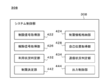
- 1 schematically shows an example of the internal configuration of the system control unit 308.
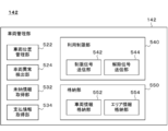
- An example of the vehicle management unit 142 is schematically shown.
- An example of the data table 600 is schematically shown.
- 1 schematically shows an example of a system configuration of a computer 3000.
- FIG. 1 schematically shows an example of a system configuration of a vehicle management system 100.
- the vehicle management system 100 includes a vehicle 120, for example.
- the vehicle management system 100 includes, for example, a management server 140.
- the vehicle 120 has, for example, a vehicle control unit 122, a self-position estimation unit 124, a drive system 126, and a power supply system 128.
- the units of the vehicle 120 are configured to send and receive information to and from each other, for example.
- the management server 140 includes, for example, a vehicle management unit 142 and a settlement management unit 144.
- the units of the management server 140 are configured to send and receive information to and from each other, for example.
- the vehicle 120 and the management server 140 are configured to send and receive information to and from each other, for example, via the communication network 10. At least one of the vehicle 120 and the management server 140 may be configured to send and receive information to and from the communication terminal 22 used by the user 20 of the vehicle 120.
- the user 20 may be an owner who owns the vehicle 120 or a user who uses the vehicle 120.
- the communication network 10 may be a wired communication transmission path, a wireless communication transmission path, or a combination of a wireless communication transmission path and a wired communication transmission path. ..
- the communication network 10 may include a wireless packet communication network, the Internet, a P2P network, a dedicated line, a VPN, a power line communication line, or the like.
- the communication network 10 may include (i) a mobile communication network such as a mobile phone network, (ii) a wireless MAN (for example, WiMAX (registered trademark)), a wireless LAN (for example, WiFi (registered trademark)). )), Bluetooth (registered trademark), Zigbee (registered trademark), NFC (Near Field Communication), and other wireless data communication networks may be included.
- the communication network 10 includes V2X such as vehicle-to-vehicle communication (sometimes referred to as V2V), road-to-vehicle communication (sometimes referred to as V2I), pedestrian-to-vehicle communication (sometimes referred to as V2P). May include a network for directing.
- V2X vehicle-to-vehicle communication
- V2I road-to-vehicle communication
- V2P pedestrian-to-vehicle communication
- V2X such as vehicle-to-vehicle communication (sometimes referred to as V2V), road-to-vehicle communication (sometimes referred to as V2I), pedestrian-to-vehicle communication (sometimes referred to as V2P). May include a network for directing.
- the communication terminal 22 may be any information processing device used by the user 20, and the details thereof are not particularly limited.
- Examples of the communication terminal 22 include a personal computer and a mobile terminal.
- Examples of the mobile terminal include a mobile phone, a smartphone, a PDA, a tablet, a notebook computer or a laptop computer, and a wearable computer.
- the vehicle management system 100 manages one or more vehicles 120.
- the vehicle management system 100 manages the usage status of each of the one or more vehicles 120.
- the user of the vehicle 120 pays the usage fee of the vehicle 120 when using the vehicle 120, for example.
- the usage fee payment method may be a prepaid method or a postpaid method.
- the vehicle management system 100 may manage the payment status of the usage fee for each of the one or more vehicles 120.
- the vehicle management system 100 may manage the usage status of each of the one or more power supply systems 128.
- the user of the vehicle 120 pays the usage fee of the power supply system 128 mounted on the vehicle 120 when using the vehicle 120, for example.
- the usage fee payment method may be a prepaid method or a postpaid method. In this case, the vehicle management system 100 may manage the payment status of the usage charge of each of the one or more power supply systems 128.
- the vehicle management system 100 includes a vehicle 120 or a power supply system by the user 20 when an abnormality occurs in the vehicle 120 or the power supply system 128 to be managed or a payment of the usage charge is delayed. Restrict the use of 128.
- the use of the vehicle 120 or the power supply system 128 may be restricted at an appropriate timing in consideration of the convenience and safety of the user 20.
- the use of the vehicle 120 or the power supply system 128 may be restricted at an appropriate timing before the storage battery or the fuel cartridge for the fuel cell is replaced.
- the vehicle management system 100 removes the above restrictions.
- the collateral for the payment is provided, or the payment is guaranteed, the vehicle management system 100 releases the restriction.
- the vehicle 120 carries out a work of carrying at least one of a person and an article (sometimes referred to as a carrying work).
- the vehicle 120 may carry out the carrying work by a driver's operation, or may carry out the carrying work by automatic driving.
- the work performed by the vehicle 120 is not limited to transportation work.
- the vehicle 120 may use the electric power to perform an arbitrary work instead of or in addition to the carrying work.
- the vehicle 120 is exemplified by an automobile, a motorcycle, a train, and the like.
- motorcycles include (i) motorcycles, (ii) three-wheeled motorcycles, (iii) Segway (registered trademark), kickboards with a power unit (registered trademark), skateboards with a power unit, such as a standing ride having a power unit.
- a two-wheeled vehicle or a three-wheeled vehicle is exemplified.
- the vehicle control unit 122 controls each unit of the vehicle 120.
- the vehicle control unit 122 controls the operation of the drive system 126.
- the vehicle controller 122 may control the operation of the power supply system 128.
- the vehicle control unit 122 receives, from the vehicle management unit 142 of the management server 140, a signal for restricting the use of the vehicle 120 or the power supply system 128 (sometimes referred to as a restriction signal). ..
- the vehicle control unit 122 transmits, for example, a restriction signal to the power supply system 128.
- the vehicle control unit 122 receives, from the vehicle management unit 142, a signal (sometimes referred to as a cancellation signal) for canceling the restriction on the use of the vehicle 120 or the power supply system 128. In this case, the vehicle control unit 122 transmits, for example, a cancellation signal to the power supply system 128. Details of the vehicle control unit 122 will be described later.
- the self-position estimation unit 124 estimates the position of the vehicle management system 100.
- the self-position estimating unit 124 includes (i) a positioning system that estimates the current position by using a GPS signal, (ii) a system that estimates the current position by using the radio field intensity of a radio signal, and (iii) an acceleration sensor.
- a gyro sensor, a geomagnetic sensor, a rotary encoder, or the like may be used to calculate the displacement from the reference point, and at least one of the systems that estimates the current position may be included.
- the drive system 126 uses the electric power supplied from the power supply system 128 to move the vehicle 120.
- the drive system 126 may include an electric motor (not shown) that converts electric energy supplied from the power supply system 128 into mechanical energy.
- the drive system 126 may use the power generated by the electric motor to move the vehicle 120.
- the drive system 126 cannot move the vehicle 120.
- the electric power supplied from the power supply system 128 is reduced, the drive system 126 cannot move the vehicle 120 at high speed.
- the power supply system 128 supplies electric power to each part of the vehicle 120.
- Power system 128 may include a fuel cell.
- the power supply system 128 obtains the restriction signal from the vehicle controller 122.
- the power supply system 128 receives power from the power supply system 128 to the drive system 126 at a timing, for example, after the restriction signal is obtained, in consideration of the convenience and safety of the user 20, and as early as possible. Limit supply.
- the power supply system 128 obtains the release signal from the vehicle control unit 122. In this case, for example, the restriction on the supply of electric power from the power supply system 128 to the drive system 126 is released. Details of the power supply system 128 will be described later.
- the management server 140 manages one or more vehicles 120.
- the vehicle management unit 142 manages the usage status of each of the one or more vehicles 120.
- the vehicle management unit 142 may detect that an abnormality has occurred in the vehicle 120.
- the vehicle management unit 142 may manage the usage status of one or more power supply systems 128.
- the vehicle management unit 142 may detect that an abnormality has occurred in the power supply system 128.
- the vehicle management unit 142 may restrict the use of the vehicle 120 or the power supply system 128 or release the restriction when a predetermined condition is satisfied.
- the vehicle management unit 142 may limit the use of the vehicle 120 by limiting the use of the power supply system 128. Details of the vehicle management unit 142 will be described later.
- the settlement management unit 144 manages the fluctuation of the usage authority for each of the one or more vehicles 120. For example, the payment status of the usage fee for each of the one or more vehicles 120 is managed.
- the vehicle management system 100 manages changes in usage authority for each of the one or more power supply systems 128. For example, the payment status of each usage charge of one or more power supply systems 128 may be managed.
- Examples of changes in usage rights include the occurrence, modification, and disappearance of usage rights.
- the usage right of the vehicle 120 is generated when the usage fee of the vehicle 120 is paid, collateral regarding the payment of the usage fee is provided, or the payment of the usage fee is guaranteed.
- the use authority of the vehicle 120 is changed.
- the usage right of the vehicle 120 disappears.
- the settlement management unit 144 monitors the payment status of the usage fee for each of the one or more vehicles 120 and detects that the usage authority for the specific vehicle 120 has disappeared. For example, the settlement management unit 144 detects the occurrence of payment delay (sometimes referred to as delinquency or delinquency). The settlement management unit 144 may output information indicating that the usage authority regarding the specific vehicle 120 has disappeared to the vehicle management unit 142.
- the settlement management unit 144 may output information indicating that the usage authority regarding the specific vehicle 120 has disappeared to the vehicle management unit 142.
- the settlement management unit 144 monitors the payment status of the usage fee for each of the one or more vehicles 120 and detects that the usage authorization for the specific vehicle 120 has occurred. For example, the settlement management unit 144 detects payment of a usage fee, elimination of payment delay, and the like. The settlement management unit 144 may output to the vehicle management unit 142 information indicating that the usage right for the specific vehicle 120 has occurred.
- the vehicle management system 100 may be an example of a control device, a management device, and a management system.
- the vehicle 120 may be an example of a work machine.
- the drive system 126 may be an example of a work machine.
- the power supply system 128 may be an example of a power supply device.
- the management server 140 may be an example of a management device.
- the vehicle management unit 142 may be an example of a management device.
- the limit signal may be an example of a limit request.
- the release signal may be an example of a release request.
- vehicle management system 100 the details of the vehicle management system 100 will be described by taking the case where the vehicle management system 100 manages one or more vehicles 120 as an example.
- vehicle management system 100 is not limited to this embodiment.
- vehicle management system 100 may manage one or more power supply systems 128 mounted on one or more vehicles 120.
- the power supply system 128 is managed according to a procedure similar to the procedure for managing the vehicle 120, for example.
- the details of the work machine have been described by taking the case where the vehicle 120, which is an example of the work machine, carries out the transportation work as an example.
- the work machine is not limited to vehicle 120.
- Other examples of work machines include transportation equipment, transportation equipment, cleaning equipment, air conditioning equipment, lighting equipment, robots, and the like.
- the transportation device include a moving body, a heavy machine, an agricultural work machine, a snow blower, an elevator, and an escalator.
- the moving body include a vehicle, a ship, and a flying body.
- the ship include a ship, a hovercraft, a watercraft, a submarine, a submersible, and an underwater scooter.
- Examples of the flying body include an airplane, an airship or balloons, a balloon, a helicopter, a drone, and the like.
- Examples of the transportation equipment include a pump, a blower, a sprayer, and a washing machine.
- Examples of the cleaning device include a vacuum cleaner and a washing machine.
- the vehicle control unit 122 transfers the limit signal and the release signal to the power supply system 128, and the controller of the power supply system 128 determines execution and release of the limit regarding power supply. Details were explained.
- the vehicle 120 is not limited to this embodiment.
- the vehicle control unit 122 may receive the restriction signal and the cancellation signal and determine whether to execute the restriction or cancel the restriction regarding the power supply.
- the vehicle control unit 122 may be an example of a control device.
- Each unit of the vehicle management system 100 may be realized by hardware, software, or hardware and software. At least a part of each unit of the vehicle management system 100 may be realized by a single server or may be realized by a plurality of servers. At least a part of each unit of the vehicle management system 100 may be realized on a virtual machine or a cloud system. At least a part of each unit of the vehicle management system 100 may be realized by a personal computer or a mobile terminal. Examples of the mobile terminal include a mobile phone, a smartphone, a PDA, a tablet, a notebook computer or a laptop computer, and a wearable computer. Each unit of the vehicle management system 100 may store information using a distributed ledger technology such as a block chain or a distributed network.
- a distributed ledger technology such as a block chain or a distributed network.
- the constituent elements realized by the software define the operation related to the constituent elements in an information processing device having a general configuration. It may be realized by activating the program.
- the information processing apparatus includes, for example, (i) a data processing apparatus having a processor such as CPU and GPU, ROM, RAM, communication interface, etc., and (ii) keyboard, touch panel, camera, microphone, various sensors, GPS receiver. And an input device such as (iii) a display device, a speaker, a vibration device, and the like, and (iv) a storage device (including an external storage device) such as a memory and a HDD.
- the data processing device or the storage device may store a program.
- the above program may be stored in a non-transitory computer-readable recording medium.
- the above program causes the information processing apparatus to execute the operation defined by the program by being executed by the processor.
- the program may be stored in a non-transitory computer-readable recording medium.
- the program may be stored in a computer-readable medium such as a CD-ROM, a DVD-ROM, a memory, a hard disk, or may be stored in a storage device connected to the network.
- the program may be installed in a computer forming at least a part of the vehicle management system 100 from a computer-readable medium or a storage device connected to a network.
- the computer may function as at least a part of each unit of the vehicle management system 100 by executing the program.
- the program that causes the computer to function as at least a part of each unit of the vehicle management system 100 may include a module that defines the operation of each unit of the vehicle management system 100. These programs or modules work on a data processing device, an input device, an output device, a storage device, or the like to cause a computer to function as each unit of the vehicle management system 100, or cause the computer to perform an information processing method in each unit of the vehicle management system 100. Let it run.
- the information processing described in the program functions as a specific means in which the software related to the program and various hardware resources of the vehicle management system 100 cooperate with each other when the program is read by the computer. .. Then, the above specific means realizes the calculation or processing of information according to the purpose of use of the computer in the present embodiment, whereby the vehicle management system 100 according to the purpose of use is constructed.
- the above program may be a program for causing the computer of the vehicle 120 to function as the vehicle control unit 122.
- the above program may be a program for causing the computer of the vehicle 120 to execute the information processing method in the vehicle control unit 122.
- the above program may be a program for causing a computer of the power supply system 128 to function as a controller of the power supply system 128.
- the above program may be a program for causing a computer of the power supply system 128 to execute the information processing method in the power supply system 128.
- the above program may be a program for causing a computer to function as the management server 140.
- the above program may be a program for causing a computer to execute the information processing method in the management server 140.
- the above information processing method may be a control method for controlling a power supply device that supplies power to the work machine.
- the above power supply device includes, for example, a fuel cell.
- the control method described above includes, for example, a restriction request acquisition step of acquiring a restriction request for restricting the supply of power from the power supply device to the work machine via the communication network.
- the above-described control method has, for example, a limiting step of limiting the supply of electric power from the power supply device to the working machine when the limiting request is obtained in the limiting request obtaining step.
- the above information processing method may be a management method for managing a power supply device that supplies power to the work machine.
- the above power supply device includes, for example, a fuel cell.
- the above management method includes, for example, an event detection step of detecting the occurrence of a predetermined first event regarding at least one of the work machine and the power supply device.
- a restriction request for restricting the supply of electric power from the power supply device to the work machine is transmitted via the communication network.
- a limit request transmitting step for transmitting to at least one of the work machine and the power supply device.
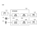
- FIG. 2 schematically shows an example of the internal configuration of the vehicle control unit 122.
- the vehicle control unit 122 includes a communication control unit 222, an input/output control unit 224, a drive control unit 226, and a power supply control unit 228.
- the communication control unit 222 controls communication between the vehicle 120 and at least one of the communication terminal 22 and the management server 140.
- the communication control unit 222 may be various communication interfaces.
- the communication control unit 222 transmits the information output by each unit of the vehicle control unit 122 to at least one of the communication terminal 22 and the management server 140.
- the communication control unit 222 may output the information acquired from at least one of the communication terminals 22 and 140 to at least one of the input/output control unit 224, the drive control unit 226, and the power supply control unit 228.
- the input/output control unit 224 controls an input device that receives an input from the user 20.
- the input/output control unit 224 may send the information input by the user 20 to the input device to the management server 140.
- the input/output control unit 224 may output the information input by the user 20 to the input device to at least one of the drive control unit 226 and the power supply control unit 228.
- Examples of the input device include a touch panel, a keyboard, a pointing device, a microphone, a voice input system, a voice analysis system, a camera, a gesture input system, and an image analysis system.
- the input/output control unit 224 controls an output device that outputs information to the user 20.
- the input/output control unit 224 may output information acquired from at least one of the communication control unit 222, the drive control unit 226, and the power supply control unit 228 to the user 20.
- Examples of the output device include a display, a projector and a speaker.
- the drive control unit 226 controls the operation of the drive system 126 to control the movement of the vehicle 120.
- the drive control unit 226 controls, for example, starting, acceleration, deceleration, direction change, stop, etc. of the vehicle 120. As a result, transportation work is carried out.
- the power supply control unit 228 controls the operation of the power supply system 128 and controls the supply of electric power from the power supply system 128 to each unit of the vehicle 120.
- the power supply controller 228 may control the supply of power from the power supply system 128 to the drive system 126.
- the power control unit 228 may control activation and deactivation of the power system 128. For example, when the input/output control unit 224 acquires a command from the user 20 to start using the vehicle 120, the power supply control unit 228 issues a command to activate the power supply system 128. Send to 128. Similarly, when the input/output control unit 224 acquires a command from the user 20 for ending the use of the vehicle 120, the power supply control unit 228 outputs a command for ending the power supply system 128 to the power supply. Send to system 128.
- At least one of the output voltage, output current, output power, and output rate of the power supply system 128 may be controlled.
- the power supply controller 228 may control the operation mode of the power supply system 128.
- the operation mode is selected from the group consisting of, for example, (i) magnitude of output power, (ii) followability or responsiveness to output command, (iii) fuel efficiency or power generation efficiency, and (iv) suppression of deterioration.
- One or more characteristics may be associated with an operating condition for giving priority to other characteristics that are not selected.
- the power supply control unit 228 transfers the limit signal to the power supply control unit 228.
- the power supply control unit 228 may transfer the release signal to the power supply system 128.
- FIG. 3 schematically shows an example of the internal configuration of the power supply system 128.
- the power supply system 128 includes a power generation system 302, a power storage system 304, a power conversion unit 306, and a system control unit 308.
- the power generation system 302 uses a fuel cell to generate electric power.
- the power generation system 302 may supply the generated electric power to each unit of the vehicle 120.
- the power generation system 302 supplies the generated electric power to each unit of the vehicle 120 via the electric power conversion unit 306. Details of the power generation system 302 will be described later.
- the power storage system 304 stores electric power.
- the power storage system 304 receives power via the power conversion unit 306 and stores the power.
- the power storage system 304 stores the electric power generated by the power generation system 302.
- the power storage system 304 stores the regenerated electric power from the drive system 126.
- Power storage system 304 may supply the stored electric power to each unit of vehicle 120.
- the power storage system 304 supplies the accumulated power to each unit of the vehicle 120 via the power conversion unit 306.
- the power conversion unit 306 converts power.
- the power conversion unit 306 may convert direct current into alternating current, convert alternating current into direct current, or convert an input direct current voltage into another direct current voltage.
- the power conversion unit 306 may include a bidirectional DC-DC converter.
- the power conversion unit 306 may switch the power distribution state.
- the power conversion unit 306 may switch the supply destination of the input power.
- the power conversion unit 306 may supply the power generated by the power generation system 302 to each unit of the vehicle 120.
- the power conversion unit 306 may supply the power generated by the power generation system 302 to the power storage system 304.
- the power conversion unit 306 may supply the power stored in the power storage system 304 to the power generation system 302.
- Electric power conversion unit 306 may supply the electric power accumulated in power storage system 304 to each unit of vehicle 120.
- the power conversion unit 306 may supply the regenerative power from the drive system 126 to the power storage system 304.
- the system control unit 308 controls the power supply system 128. More specifically, the system control unit 308 controls the operation of at least one of the power generation system 302 and the power conversion unit 306 to adjust the output of the power supply system 128.
- the system control unit 308 controls the operation of the power generation system 302 to adjust the power generation amount.
- the system control unit 308 may control the operation of the power generation system 302 according to a command from the power supply control unit 228.
- the system control unit 308 controls starting and stopping of the power generation system 302.
- the system control unit 308 may control at least one of the output voltage, the output current, the output power, and the output rate of the power generation system 302.
- the system control unit 308 may control the operation mode of the power generation system 302.
- the system control unit 308 may control the operation of the power generation system 302 based on the limit signal.
- the system control unit 308 may control the operation of the power generation system 302 based on the release signal.
- system control unit 308 controls the operation of the power conversion unit 306 to adjust the amount of power supplied from the power supply system 128 to each unit of the vehicle 120.
- the system control unit 308 may control the operation of the power conversion unit 306 according to a command from the power supply control unit 228.
- the system control unit 308 controls whether power is supplied from the power supply system 128 to each unit of the vehicle 120.
- the system control unit 308 may control whether power is supplied from the power supply system 128 to a specific device (for example, the drive system 126) of the vehicle 120.
- the system control unit 308 controls at least one of output voltage, output current, output power, and output rate of power supplied from the power supply system 128 to each unit of the vehicle 120.
- the system control unit 308 may adjust the balance between the electric power supplied from the power generation system 302 and the electric power supplied from the power storage system 304.
- the system control unit 308 may control the operation of the power conversion unit 306 based on the limit signal.
- the system control unit 308 may control the operation of the power conversion unit 306 based on the release signal. Details of the system control unit 308 will be described later.
- the power generation system 302 includes a fuel cell unit 310, a fuel supply unit 312, an oxidant supply unit 314, and a temperature adjustment medium supply unit 316.
- the fuel cell unit 310 includes a communication connector 322, a power connector 324, and a power generation utility connector 326.
- the fuel cell unit 310 includes an FC controller 330, a power generator 340, and an auxiliary battery 350.
- the fuel cell unit 310 uses the fuel supplied from the fuel supply unit 312 and the fuel supplied from the oxidant supply unit 314 to generate electric power.
- the temperature of the fuel cell unit 310 is adjusted by the temperature adjustment medium supplied from the temperature adjustment medium supply unit 316.
- the electric power generated by the fuel cell unit 310 is supplied to each unit of the vehicle 120 via the electric power conversion unit 306, for example.
- the fuel cell unit 310 may control the operation of at least one of the fuel supply unit 312, the oxidant supply unit 314, and the temperature adjustment medium supply unit 316.
- the fuel cell unit 310 may operate according to a command from the system control unit 308.
- the fuel cell unit 310 may be a unit in which at least the FC control unit 330, the power generation unit 340, piping and wiring are packaged.
- the fuel cell unit 310 may be a unit in which at least the FC control unit 330, the power generation unit 340, the auxiliary battery 350, the piping and the wiring are packaged.
- the components of the fuel cell unit 310 may be housed in a single housing, or may be housed by being divided into a plurality of housings.
- the fuel cell unit 310 is attached to the power generation system 302 by being connected to, for example, utility pipes and power cables arranged in the power generation system 302.
- the fuel cell unit 310 may be attached to the power generation system 302 by being connected to the utility piping, the power cable, and the communication cable arranged in the power generation system 302.
- the fuel cell unit 310 is mounted on the vehicle 120.
- the fuel cell unit 310 is attached to the power generation system 302 so that a general user of the vehicle 120 cannot easily remove it.
- the fuel cell unit 310 is fixed to a predetermined position of the power generation system 302, for example.
- the fuel cell unit 310 is detachably attached to the power generation system 302.
- the general user of the vehicle 120 attaches the fuel cell unit 310 removed from the vehicle 120 to another work machine and operates the other work machine with the electric power generated by the fuel cell unit 310. You can
- the fuel supply unit 312 supplies fuel for power generation to the fuel cell unit 310.
- the fuel for power generation may be hydrogen or a compound containing hydrogen.
- the fuel supply unit 312 may include a sensor (not shown) that measures the flow rate of the fuel, and a flow rate adjustment unit (not shown) that adjusts the flow rate of the fuel.
- the fuel supply unit 312 may operate according to a command from the fuel cell unit 310.
- the fuel supply unit 312 is supplemented with fuel from the outside.
- the fuel supply unit 312 may have a replenishment pipe and a fuel container (not shown) for receiving the fuel replenished from the outside.
- the fuel supply unit 312 may have a member for permitting or prohibiting access to the replenishment pipe from the outside.
- the member may be a lid or a stopper arranged at one end of the supplementary pipe.
- the fuel supply unit 312 may switch between a state in which the above member cannot be removed from the supplementary pipe and a state in which the above member can be removed from the supplemental pipe in accordance with a command from the system control unit 308.
- the fuel supply unit 312 may include a replaceable fuel cartridge (not shown).
- the fuel supply unit 312 is in a state where the fuel supply unit 312 cannot remove the fuel cartridge from the fuel supply unit 312 according to an instruction from the system control unit 308, and the fuel supply unit 312 removes the fuel cartridge from the fuel supply unit 312. You may switch to the state where you can.
- the oxidant supply unit 314 supplies the fuel cell unit 310 with an oxidant for power generation.
- the oxidant for power generation may be oxygen or air.
- the oxidant supply unit 314 may include a sensor (not shown) that measures the flow rate of the oxidant, and a flow rate adjustment unit (not shown) that adjusts the flow rate of the oxidant.
- the oxidant supply unit 314 may operate according to instructions from the fuel cell unit 310.
- the oxidant supply unit 314 may have a pump or a blower (not shown) for sucking air serving as an oxidant from the outside of the power generation system 302.
- the oxidant supply unit 314 may be connected to an air supply pipe (not shown) arranged in the vehicle 120.
- the temperature adjustment medium supply unit 316 supplies the temperature adjustment medium for adjusting the temperature of the power generation stack of the fuel cell unit 310 to the fuel cell unit 310.
- the temperature adjusting medium include water, ethylene glycol, long life coolant (sometimes referred to as LLC), and the like.
- the temperature adjustment medium supply unit 316 may include a sensor (not shown) that measures the flow rate of the temperature adjustment medium, and a flow rate adjustment unit (not shown) that adjusts the flow rate of the temperature adjustment medium.
- the temperature adjustment medium supply unit 316 may operate according to a command from the fuel cell unit 310.
- the temperature adjustment medium supply unit 316 may include a heat exchanger (not shown) for adjusting the temperature of the temperature adjustment medium.
- a radiator is illustrated as a heat exchanger.
- the communication connector 322 connects the communication cable arranged in the fuel cell unit 310 and the communication cable arranged in the power generation system 302.
- the communication cable arranged in the fuel cell unit 310 and the communication cable arranged in the power generation system 302 may be wired or wirelessly connected.
- the fuel cell unit 310 may send/receive information to/from a communication cable arranged in the power generation system 302, the system control unit 308, or the vehicle control unit 122 via a wireless communication device.
- the power connector 324 electrically connects the power cable arranged in the fuel cell unit 310 and the power cable arranged in the power generation system 302.
- the power cable arranged in the fuel cell unit 310 and the power cable arranged in the power generation system 302 may be connected by wire or wirelessly.
- the fuel cell unit 310 may be electrically connected to the vehicle 120 or the power conversion unit 306 via a wireless power supply device.
- the power generation utility connector 326 connects the utility pipe arranged in the fuel cell unit 310 and the utility pipe arranged in the power generation system 302.
- the utility used to operate the fuel cell unit 310 can be transferred between the power generation system 302 and the fuel cell unit 310.
- the utility can be transferred between the vehicle 120 or the power generation system 302 and the fuel cell unit 310.
- the fuel supply unit 312 and the fuel cell unit 310 it becomes possible to exchange fuel between the fuel supply unit 312 and the fuel cell unit 310. It is possible to exchange the oxidant between the oxidant supply unit 314 and the fuel cell unit 310.
- the temperature adjustment medium or heat can be transferred between the temperature adjustment medium supply unit 316 and the fuel cell unit 310. Further, between the fuel cell unit 310 and the vehicle 120 or the power generation system 302, it becomes possible to send and receive wastewater and exhaust gas generated due to power generation in the fuel cell unit 310.
- the FC control unit 330 controls the fuel cell unit 310.
- the FC control unit 330 controls the power generation of the fuel cell unit 310.
- the FC controller 330 may control at least one of the output voltage, output current, output power, and output rate of the fuel cell unit 310.
- the FC controller 330 may control the power generation of the fuel cell unit 310 by controlling the operation of at least one of the fuel supply unit 312, the oxidant supply unit 314, and the temperature adjustment medium supply unit 316.
- the FC controller 330 may operate according to a command from the system controller 308.
- the power generation unit 340 generates electricity.
- the power generation section 340 may include a fuel cell.
- the fuel cell reacts the fuel supplied from the fuel supply unit 312 with the oxidant supplied from the oxidant supply unit 314 to generate electricity.
- the power generation unit 340 may be electrically connected to the power connector 324.
- the power generation unit 340 may be electrically connected to the auxiliary battery 350.
- the power generation unit 340 may supply a part of the generated electricity to the auxiliary battery 350.
- the oxidant supply unit 314 in order to activate the power generation unit 340, electric power is required to activate the fuel supply unit 312 and the oxidant supply unit 314 that supply the oxidant and fuel to the power generation unit.
- the oxidant supply unit 314 often includes a fan for sending air as the oxidant to the power generation unit 340 under pressure.
- the power consumption of the above fan is relatively large. Therefore, it is desirable to secure the electric power for operating the oxidant supply unit 314 in preparation for the activation of the power generation unit 340.
- the auxiliary battery 350 stores electric power for activating at least one of the fuel supply unit 312, the oxidant supply unit 314, and the temperature adjustment medium supply unit 316.
- the auxiliary battery 350 may store electric power for starting the oxidant supply unit 314.
- the auxiliary battery 350 may be electrically connected to the power connector 324.
- the auxiliary battery 350 may store the electric power supplied from the power conversion unit 306.
- the auxiliary battery 350 may be electrically connected to the power generation unit 340.
- the auxiliary battery 350 may store the electric power supplied from the power generation unit 340.
- At least one of the fuel supply unit 312, the oxidant supply unit 314, and the temperature adjustment medium supply unit 316 is configured to operate by using the electric power supplied from the power storage system 304 when the fuel cell unit 310 is started. It may have been done. At least one of the fuel supply unit 312, the oxidant supply unit 314, and the temperature adjustment medium supply unit 316 has the power supplied from the power storage system 304 and the power generated by the fuel cell unit 310 when the fuel cell unit 310 is activated. May be configured to operate.
- At least one of the fuel supply unit 312, the oxidant supply unit 314, and the temperature adjustment medium supply unit 316 is configured such that, when the fuel cell unit 310 is started, the remaining capacity of the auxiliary battery 350 is out of a predetermined numerical range. In some cases, it may be configured to operate using electric power supplied from the power storage system 304.
- the “numeric range” is not limited to the case where both upper and lower limits are set. In the “numerical range”, only the upper limit may be set, or only the lower limit may be set.
- the oxidant supply unit 314 may operate using the electric power generated by the power generation unit 340 after the amount of power generated by the power generation unit 340 satisfies a predetermined condition. For example, when the power generation amount of the power generation unit 340 is smaller than a predetermined threshold value, the oxidant supply unit 314 uses the power supplied from the auxiliary battery 350 or the power storage system 304 to oxidize the power generation unit 340. Supply the agent. When the power generation amount of the power generation unit 340 is larger than the threshold value, the oxidant supply unit 314 uses the electric power generated by the power generation unit 340 to supply the oxidant to the power generation unit 340.
- the oxidant supply amount is the electric power generated by the power generation unit 340 by the oxidant supply unit 314. It may be smaller than the supply amount of the oxidant when using.
- the supply amount of the oxidant may change according to the magnitude of the electric power generated by the power generation unit 340.
- the supply amount of the oxidizing agent may continuously change or may change stepwise according to the magnitude of the electric power generated by the power generation unit 340.
- the details of the fuel cell unit 310 have been described as an example in which the fuel cell unit 310 does not include the fuel supply unit 312, the oxidant supply unit 314, and the temperature adjustment medium supply unit 316.
- the fuel cell unit 310 is not limited to this embodiment.
- the fuel cell unit 310 may include at least one of the fuel supply unit 312, the oxidant supply unit 314, and the temperature adjustment medium supply unit 316.
- the details of the power supply system 128 have been described by taking the case where the fuel cell unit 310 is a packaged unit as an example.
- the power supply system 128 is not limited to this embodiment.
- the power generation system 302 may be a packaged unit.
- the power supply system 128 may be a packaged unit.
- the details of the power supply system 128 have been described by taking the case where the fuel cell unit 310 is configured to be detachable from the power generation system 302 as an example.
- the power supply system 128 is not limited to this embodiment.
- the power generation system 302 may be configured to be removable from the power supply system 128.
- the power supply system 128 may be configured to be removable from the vehicle 120.
- FIG. 4 schematically shows an example of the internal configuration of the system control unit 308.
- the system control unit 308 includes the restriction signal acquisition unit 422, the restriction information storage unit 424, the cancellation signal acquisition unit 426, the self-position acquisition unit 428, the usage status determination unit 432, and the communication status determination unit. 434, a limit determination unit 442, and an output control unit 444.
- the restriction signal acquisition unit 422 receives a signal (sometimes referred to as a restriction signal) requesting to restrict the supply of electric power from the power supply system 128 to each part or part of the vehicle 120. To do.
- the restriction signal is transmitted from the management server 140, for example.
- the restriction signal acquisition unit 422 may output information indicating that the restriction signal has been received to the restriction determination unit 442. For example, the restriction signal acquisition unit 422 transfers the restriction signal to the restriction determination unit 442.
- the restriction signal may include information indicating the conditions related to execution of restriction.
- the restriction signal acquisition unit 422 may store information indicating a condition regarding execution of restriction in the restriction information storage unit 424.
- the restriction information storage unit 424 stores information indicating conditions regarding execution of restrictions.
- information indicating the condition regarding the execution of the restriction information indicating an area where the execution of the restriction is permitted, information indicating an area where the execution of the restriction is prohibited, information indicating an area where the execution of the restriction can be postponed, and the execution of the restriction Information indicating the period during which restriction execution is permitted, information indicating the period during which restriction execution is prohibited, information indicating the period during which restriction execution can be postponed, information indicating the time zone during which restriction execution is permitted, and restriction execution Information indicating a prohibited time zone, information indicating a time zone in which execution of the restriction can be postponed, information indicating a communication status in which execution of the restriction is permitted, information indicating a communication status in which execution of the restriction is prohibited, For example, information indicating a communication status in which execution can be postponed is exemplified.
- the restriction information storage unit 424 may store information indicating the execution status of restrictions. For example, the limit information storage unit 424 stores information indicating whether or not power supply is currently limited. The restriction information storage unit 424 may store information indicating the content of the restriction. The restriction information storage unit 424 may extract information that matches the request in response to the request from the restriction determination unit 442 or the output control unit 444.
- the cancellation signal acquisition unit 426 receives a signal (sometimes referred to as a cancellation signal) requesting cancellation of the above restriction on power supply.
- the cancellation signal is transmitted from the management server 140, for example.
- the cancellation signal acquisition unit 426 may output information indicating that the cancellation signal has been received to the restriction determination unit 442.
- the restriction signal acquisition unit 422 transfers the cancellation signal to the restriction determination unit 442.
- the self-position acquisition unit 428 acquires information indicating the current position of the vehicle 120.
- the self-position acquisition unit 428 acquires, from the vehicle control unit 122, information indicating the estimated value of the current position of the vehicle 120 output by the self-position estimation unit 124.
- the self-position acquisition unit 428 may output information indicating the current position of the vehicle 120 to the restriction determination unit 442.
- the usage status determination unit 432 determines the usage status of the vehicle 120. Examples of the usage status of the vehicle 120 include that the user 20 has started using the vehicle 120, that the user 20 is using the vehicle 120, that the user 20 has finished using the vehicle 120, and the like.
- the usage status determination unit 432 may output information indicating the determination result to the restriction determination unit 442.
- the usage status determination unit 432 detects the start of usage of the vehicle 120. As described above, for example, when the input/output control unit 224 obtains a command from the user 20 to start using the vehicle 120, the power supply control unit 228 activates the power supply system 128. The instructions are sent to the power supply system 128. The command to start using the vehicle 120 may be to turn on a start switch or an ignition key of the vehicle 120. The usage status determination unit 432 may detect the start of usage of the vehicle 120 by receiving the command for activating the power supply system 128.
- the usage status determination unit 432 detects the end of usage of the vehicle 120. As described above, for example, when the input/output control unit 224 obtains a command from the user 20 for ending the use of the vehicle 120, the power supply control unit 228 causes the power supply system 128 to end. The instructions are sent to the power supply system 128. The command for ending the use of vehicle 120 may be to turn off a start switch or an ignition key of vehicle 120. The usage determining unit 432 may detect the end of the use of the vehicle 120 by receiving the command for ending the power supply system 128.
- the communication status determination unit 434 determines the communication status of the vehicle 120.
- the communication status determination unit 434 may determine the communication status of the vehicle 120 by analyzing the communication between the communication control unit 222 and the communication terminal 22 and the management server 140, for example.
- the communication status determination unit 434 may output information indicating the determination result to the restriction determination unit 442.
- radio wave status examples include radio wave reception level, radio wave intensity, RSCP (Received Signal Code Power), and CID (Cell ID).
- communication quality examples include communication speed, data communication throughput, and data communication latency.
- the restriction determination unit 442 determines to restrict the supply of electric power from the power supply system 128 to each part or part of the vehicle 120 when the restriction signal acquisition unit 422 acquires the restriction signal.
- the limit determining unit 442 may determine to execute the above-mentioned limit regarding power supply at an appropriate timing after the limit signal acquiring unit 422 acquires the limit signal.
- the restriction determination unit 442 determines to cancel the restriction regarding the power supply.
- the restriction determination unit 442 may acquire the information indicating that the restriction signal has been received from the restriction signal acquisition unit 422.
- the restriction signal acquisition unit 422 may access the restriction information storage unit 424 to acquire information indicating a condition regarding execution of restriction.
- the restriction determination unit 442 may acquire the information indicating that the cancellation signal is received from the cancellation signal acquisition unit 426.
- the restriction signal acquisition unit 422 may acquire information indicating the current position of the vehicle 120 from the self-position acquisition unit 428.
- the restriction signal acquisition unit 422 may acquire information indicating the determination result regarding the usage status of the vehicle 120 from the usage status determination unit 432.
- the restriction signal acquisition unit 422 may acquire the information indicating the determination result regarding the communication status of the vehicle 120 from the communication status determination unit 434.
- the limitation determining unit 442 starts the above-described limitation regarding power supply when the usage status determining unit 432 detects the end of the use of the vehicle 120 after the limitation signal acquiring unit 422 acquires the limitation signal. You may decide to do.
- the restriction determination unit 442 after the restriction signal acquisition unit 422 acquires the restriction signal and the usage status determination unit 432 detects the end of usage of the vehicle 120, the usage status determination unit 432 detects the start of usage of the vehicle 120. In that case, it may be decided to initiate the above limitation on power supply.
- the vehicle 120 prevents the vehicle 120 from becoming unavailable while the user 20 is driving the vehicle 120. Further, when the user 20 stops using the vehicle 120, the vehicle 120 is likely to be stopped at the destination point or an appropriate relay point. Therefore, even when the power supply from the power supply system 128 to the vehicle 120 is limited, the user 20 is likely to be able to pay the usage fee of the vehicle 120 or take a break outside the vehicle. Furthermore, after the restriction signal acquisition unit 422 acquires the restriction signal, the power supply from the power supply system 128 to the vehicle 120 is restricted at a relatively early timing. As a result, it is expected that the collection period of usage charges will be shortened and the spread of theft damage will be suppressed.
- the restriction determination unit 442 relates to the above power supply when the geographical relationship between the position of the vehicle 120 and the position of the area where the restriction is allowed to be executed satisfies a predetermined condition. You may decide to start the restriction.
- the predetermined conditions include (i) the condition that the vehicle 120 is located inside the area where the restriction is permitted, (ii) the position of the vehicle 120 and the area where the restriction is permitted. An example is the condition that the distance from the position of is smaller than a predetermined value.
- the restriction determination unit 442 determines that the restriction determination unit 442 is related to the above power supply. You may decide to start the restriction.
- the predetermined conditions include (i) the condition that the vehicle 120 is not located inside the area where the restriction is prohibited, and (ii) the position of the vehicle 120 and the restriction is permitted.
- An example is a condition that the distance from the position of the specified area is larger than a predetermined value.
- the limitation determining unit 442 may determine whether to start limiting the supply of electric power based on the communication status of the vehicle 120. For example, when the communication status of the vehicle 120 is good, the restriction signal acquisition unit 422 may start the restriction on the power supply. On the other hand, when the communication status of the vehicle 120 is not good, the restriction signal acquisition unit 422 may postpone the restriction on the power supply.
- the restriction determination unit 442 may determine whether to start the restriction of the power supply based on the situation of the surrounding environment of the vehicle 120. For example, when the weather condition around the vehicle 120 satisfies a predetermined condition, the restriction determination unit 442 may start the above restriction on the power supply. On the other hand, when the weather condition around the vehicle 120 does not satisfy the predetermined condition, the restriction signal acquisition unit 422 may postpone the restriction on the power supply.
- the predetermined conditions include (i) that the temperature is within a predetermined numerical range, that at least an index or index determined based on the temperature is within a predetermined numerical range, etc. It is illustrated.
- the above-mentioned indexes include a heat index or a wet-bulb black-ball temperature (sometimes abbreviated as WBGT), a discomfort index (sometimes abbreviated as THI), and a predicted average thermal sensation report (abbreviated as PMV).
- WBGT wet-bulb black-ball temperature
- THI discomfort index
- PMV predicted average thermal sensation report
- the standard effective temperature may be abbreviated as SET).
- the output control unit 444 limits the supply of electric power from the power supply system 128 to each unit or part of the vehicle 120 when the limit signal acquisition unit 422 acquires the limit signal.
- the output control unit 444 may execute the above restriction when the restriction determination unit 442 determines to start the above restriction on the power supply.
- the output control unit 444 for example, (i) means for stopping at least one of supply and reception of electric power, (ii) means for making the supply amount of electric power or its upper limit value smaller than a predetermined value, (iii) Means for inhibiting the start of the fuel cell, (iv) Means for inhibiting the power generation of the fuel cell, (v) Means for reducing the output power of the fuel cell or its upper limit value below a predetermined value, (vi) The fuel cell Output rate or its upper limit value is smaller than a predetermined threshold value, (vii) means for prohibiting refueling of fuel cell, (viii) removal of fuel cell or removal of fuel cartridge of fuel cell And (iX) at least one of the means for making the refillable amount of the fuel of the fuel cell smaller than a predetermined value, the supply of electric power is limited.
- the refillable amount of fuel may be the upper limit value of the fuel replenishment amount per time or the upper limit value of the fuel replenishment amount in a certain period.
- the vehicle 120 cannot move.
- power supply system 128 stops receiving electric power from vehicle 120, for example, charging of power storage system 304 and recovery of regenerative electric power become impossible. If vehicle 120 continues to operate in this state, the remaining capacity of power storage system 304 decreases. When the remaining capacity of power storage system 304 becomes smaller than a predetermined value, some operations of vehicle 120 may be limited.
- the vehicle 120 When the amount of electric power supplied from the power supply system 128 to the vehicle 120 decreases, for example, the vehicle 120 cannot move at high speed. If the activation of the fuel cell is prohibited or the power generation of the fuel cell is prohibited, the vehicle 120 can operate only within the remaining capacity of the power storage system 304. Examples of the method of prohibiting power generation include a method of stopping the supply of the oxidant and a method of stopping the supply of the fuel.
- Examples of the method of adjusting the output power or output rate of the fuel cell include a method of adjusting the output by the power conversion unit 306 and a method of adjusting the supply speed of the fuel or the oxidant.
- the vehicle 120 can operate only within the range of the remaining amount of fuel and the remaining capacity of the power storage system 304.
- a method of prohibiting the replenishment of the fuel of the fuel cell the method of keeping the fuel supply port closed, the method of inhibiting the insertion of the fuel supply nozzle into the fuel supply port, and the fuel supply to the fuel supply device Examples include a method of transmitting a signal indicating prohibition and the like.
- the fuel shortage state is maintained after the vehicle 120 runs out of fuel.
- the refillable amount of fuel in the fuel cell becomes smaller than a predetermined value, the time during which the vehicle 120 can operate by one refilling becomes short.
- An example of a method of limiting the refillable amount of fuel is a method of transmitting a signal indicating an upper limit value of the refillable amount of fuel to the fuel supply device.
- the output control unit 444 may execute the above limitation stepwise. In one embodiment, the output control unit 444 implements a specific type of restriction and gradually increases the strength of the restriction.
- the number of stages is not particularly limited. The number of steps may be two or more, three or more, four or more, or five or more.
- the output control unit 444 first changes the upper limit value of the output rate of the fuel cell to a value smaller than the normal value. This reduces the acceleration performance of the vehicle 120. As a result, the user 20 of the vehicle 120 can foresee that the power supply to the vehicle 120 will be further restricted in the future.
- the output control unit 444 changes the upper limit value of the output rate to a smaller value.
- Predetermined conditions are that the power generation amount of the fuel cell exceeds a certain value, the power consumption amount of the vehicle 120 exceeds a certain value, the operating time of the vehicle 120 exceeds a certain value, and a certain period has passed. This is exemplified.
- the output control unit 444 first implements the first type of restriction as the first step.
- the second type of restriction is implemented.
- the number of stages is not particularly limited. The number of steps may be two or more, three or more, four or more, or five or more.
- the strength of restriction may be increased stepwise in each step.
- the restriction signal acquisition unit 422 receives the restriction signal.
- the output control unit 444 limits the upper limit value of the output rate of the power supply system 128 or the fuel cell as the first step. This reduces the acceleration performance of the vehicle 120. As a result, the user 20 of the vehicle 120 can foresee that the power supply to the vehicle 120 will be further restricted in the future.
- the output control unit 444 determines the upper limit value of the amount of electric power supplied to the vehicle 120 in a second step. Less than the specified value. Predetermined conditions are that the power generation amount of the fuel cell exceeds a certain value, the power consumption amount of the vehicle 120 exceeds a certain value, the operating time of the vehicle 120 exceeds a certain value, and a certain period has passed. This is exemplified. This limits the output of drive system 126 of vehicle 120. As a result, the maximum speed of vehicle 120 is limited.
- the output control unit 444 prohibits the next fuel cell startup or fuel consumption as the third step. Limit replenishment. As a result, for example, if the unpaid state of the usage fee is not resolved, the user 20 cannot finally continue to use the vehicle 120.
- the output control unit 444 may select a method of limiting the power supply according to the situation of the vehicle 120.
- Examples of the status of the vehicle 120 include the current position of the vehicle 120, the operating status of the vehicle 120, the communication status of the vehicle 120, and the status of the surrounding environment of the vehicle 120.
- the method of limiting the power supply is not particularly limited.
- the output control unit 444 may (i) stop the power supply from the power supply system 128 to the vehicle 120, or (ii) prohibit the activation or power generation of the fuel cell.
- the predetermined stop location include (i) a parking lot arranged at or near the home or work place of the user 20, or (ii) a parking lot operated by an administration or a private company.
- the output control unit 444 uses (i) the power supply system 128 as a method of limiting the power supply.
- the amount of electric power supplied from the vehicle to the vehicle 120 or the upper limit value thereof is smaller than the rated value, (ii) the upper limit value of the output rate of the power supply system 128 or the fuel cell is smaller than the normal value, (iii) ) Select prohibition of refueling, (iv) prohibition of removal of the fuel cell or removal of the fuel cartridge of the fuel cell, or (v) reduction of the refuelable amount below the normal value. May be.
- the vehicle 120 can safely move to the parking space or the fuel station even when the power supply to the vehicle 120 is limited.
- the method of limiting the power supply is not particularly limited.
- the output control unit 444 uses (i) a power supply amount from the power supply system 128 to the vehicle 120 or an upper limit value thereof to be smaller than a rated value as a method of limiting the power supply, and (ii) the power supply system. 128 or lowering the upper limit of the output rate of the fuel cell below the normal value, (iii) prohibiting refueling, (iv) prohibiting removal of the fuel cell or removal of the fuel cartridge of the fuel cell.
- the refillable amount of fuel is selected to be smaller than the normal value.
- the output control unit 444 uses (i) the amount of power supplied from the power supply system 128 to the vehicle 120 or its upper limit value as a method of limiting the power supply from the rated value. May be selected, or (ii) the upper limit of the output rate of the power supply system 128 or the fuel cell may be selected to be smaller than the normal value. According to this embodiment, the vehicle 120 can move to a place where the communication status is good without falling into a fuel shortage.
- the method of limiting the power supply is not particularly limited.
- the output control unit 444 may (i) stop the power supply from the power supply system 128 to the vehicle 120, or (ii) prohibit the activation or power generation of the fuel cell. Select.
- the amount of power supplied from the power supply system 128 to the vehicle 120 or its upper limit value is smaller than the rated value.
- the predetermined conditions include (i) that the temperature is within a predetermined numerical range, that at least an index or index determined based on the temperature is within a predetermined numerical range, etc. It is illustrated.
- the above-mentioned indexes include a heat index or a wet-bulb black-ball temperature (sometimes abbreviated as WBGT), a discomfort index (sometimes abbreviated as THI), and a predicted average thermal sensation report (abbreviated as PMV).
- WBGT wet-bulb black-ball temperature
- THI discomfort index
- PMV predicted average thermal sensation report
- SET standard effective temperature
- the restriction signal acquisition unit 422 may be an example of a restriction request acquisition unit.
- the cancellation signal acquisition unit 426 may be an example of a cancellation request acquisition unit.
- the usage status determination unit 432 may be an example of an end detection unit and a start detection unit.
- the restriction determination unit 442 may be an example of the restriction unit.
- the output control unit 444 may be an example of a limiting unit.
- the limit signal may be an example of a limit request.
- the release signal may be an example of a release request.
- FIG. 5 schematically shows an example of the vehicle management unit 142.
- the vehicle management unit 142 includes a vehicle position management unit 522, a vehicle abnormality detection unit 524, a non-payment information acquisition unit 532, a payment information acquisition unit 534, a usage restriction unit 540, and a storage unit 550.
- the usage restriction unit 540 has a restriction signal transmission unit 542 and a cancellation signal transmission unit 544.
- the storage unit 550 includes a vehicle information storage unit 552 and an area information storage unit 554.
- the vehicle position management unit 522 manages the position information of each of the one or more vehicles 120.
- the vehicle position management unit 522 may manage the position information of each of the one or more power supply systems 128.
- the position of the power supply system 128 may be the position of the vehicle 120 in which the power supply system is mounted.
- the vehicle position management unit 522 acquires information indicating the position of the vehicle 120 at each timing from one or more vehicles 120 at any timing.
- the vehicle position management unit 522 stores, in the vehicle position management unit 522, for example, information indicating the position of the vehicle 120 and information indicating the time at which the information was acquired are associated with each other.
- the vehicle abnormality detection unit 524 detects an abnormality that has occurred in at least one of the one or more vehicles 120.
- the vehicle abnormality detection unit 524 may detect an abnormality that has occurred in at least one of the one or more power supply systems 128. Examples of the above abnormality include failure, theft and loss.
- the vehicle abnormality detection unit 524 acquires, for example, from the vehicle 120, information indicating that a failure has occurred in the vehicle 120 or the power supply system 128.
- the vehicle abnormality detection unit 524 acquires information indicating the theft or loss of the vehicle 120 or the power supply system 128 from the communication terminal 22, for example.
- the vehicle position management unit 522 stores, for example, information indicating that an abnormality has occurred in the vehicle 120 or the power supply system 128 in the vehicle position management unit 522.
- the vehicle abnormality detection unit 524 may detect that the abnormality that has occurred in at least one of the one or more vehicles 120 has been resolved.
- the vehicle position management unit 522 stores, for example, information indicating that the abnormality of the vehicle 120 or the power supply system 128 has been resolved in the vehicle position management unit 522.
- the unpaid information acquisition unit 532 receives, from the settlement management unit 144, information indicating that the usage charge of the vehicle 120 or the power supply system 128 is unpaid (sometimes referred to as unpaid information), for example. get.
- the vehicle position management unit 522 stores in the vehicle position management unit 522, for example, information indicating that the usage fee of the vehicle 120 or the power supply system 128 has not been paid.
- the payment information acquisition unit 534 acquires information indicating that the usage fee for the vehicle 120 or the power supply system 128 has been paid from the settlement management unit 144, for example.
- the vehicle position management unit 522 stores, for example, in the vehicle position management unit 522, information indicating that the usage fee of the vehicle 120 or the power supply system 128 has been paid (may be referred to as payment information).
- the usage restriction unit 540 generates at least one of the restriction signal and the cancellation signal described above. Usage restriction unit 540 transmits the generated signal to corresponding vehicle 120 or power supply system 128.
- the restriction signal transmission unit 542 determines whether or not the restriction signal transmission unit 542 has detected the abnormality of the vehicle 120 and/or the unpaid information acquisition unit 532 has acquired the unpaid information. To generate. Limit signal transmitting unit 542 transmits the generated limit signal to corresponding vehicle 120 or power supply system 128.
- the restriction signal transmitting unit 542 may transmit the generated restriction signal to the corresponding vehicle 120 or the power supply system 128 at an appropriate timing.
- the restriction signal transmission unit 542 refers to the vehicle information storage unit 552 and acquires information indicating the current position of the vehicle 120 or the power supply system 128.
- the restriction signal transmission unit 542 refers to the area information storage unit 554, and a geographical relationship between the current position of the vehicle 120 or the power supply system 128 and the position of the area where the restriction is permitted is predetermined. It is determined whether the above condition (there is a case called the first geographical condition) is satisfied.
- the restriction signal transmitting unit 542 responds to the restriction signal.
- the first geographical condition includes (i) the condition that the vehicle 120 is located inside the area where the restriction is permitted, (ii) the position of the vehicle 120 and the position where the restriction is permitted to be executed.
- An example is a condition that the distance between and is smaller than a predetermined value.
- the restriction signal transmission unit 542 may transmit information indicating a condition regarding execution of the restriction to the corresponding vehicle 120 or the power supply system 128 together with the generated restriction signal or in association with the restriction signal.
- the restriction signal transmission unit 542 refers to the area information storage unit 554, and is predetermined as the vehicle 120 or the power supply system 128 among the area where the restriction is permitted and the area where the restriction is prohibited.
- An area that satisfies the second geographical condition is extracted.
- the second geographical condition is (i) the condition that the vehicle 120 is located inside the area, and (ii) the distance between the position of the vehicle 120 and the position of the area is smaller than a predetermined value.
- the condition is exemplified.
- the restriction signal transmission unit 542 transmits the information indicating the type and position of the extracted area to the corresponding vehicle 120 or the power supply system 128 together with the restriction signal or in association with the restriction signal.
- the cancellation signal transmission unit 544 is configured to perform the above-described operation in at least one of the case where the vehicle abnormality detection unit 524 detects the elimination of the abnormality of the vehicle 120 and the case where the payment information acquisition unit 534 acquires the payment information. Generate a release signal.
- the cancellation signal transmission unit 544 transmits the generated cancellation signal to the corresponding vehicle 120 or power supply system 128.
- the storage unit 550 stores various kinds of information.
- the vehicle information storage unit 552 stores various information regarding each of the one or more vehicles 120. Details of the information stored in the vehicle information storage unit 552 will be described later.
- the area information storage unit 554 stores area information indicating the position of at least one of the area where restriction is permitted and the area where restriction is prohibited. The area information may be in a white list format or a black list format.
- the vehicle position management unit 522 may be an example of a position information acquisition unit.
- the vehicle abnormality detection unit 524 may be an example of an event detection unit.
- the unpaid information acquisition unit 532 may be an example of an event detection unit.
- the payment information acquisition unit 534 may be an example of an event detection unit.
- the restriction signal transmission unit 542 may be an example of a restriction request transmission unit, an area extraction unit, and a position determination unit.
- the cancellation signal transmission unit 544 may be an example of a cancellation request transmission unit.
- the area information storage unit 554 may be an example of the area information storage unit.
- FIG. 6 schematically shows an example of the data table 600.
- Each row of the data table 600 may be an example of vehicle information stored in the vehicle information storage unit 552.
- the data table 600 indicates a vehicle ID 622 for identifying each vehicle, information indicating a time 624, information indicating a vehicle position 626, information indicating a vehicle position 626, and a vehicle condition 628.
- the information, the information indicating the power supply status 630, the information indicating the fee payment status 632, and the information indicating the usage restriction status 634 are stored in association with each other.
- the information indicating the vehicle position 626 indicates the position of the vehicle 120 at time 624.
- the position of the vehicle 120 include the address of the position, the name of the facility arranged at the position, and the position coordinates of the position.
- the position coordinates may represent a specific position by latitude and longitude, or may represent a specific position by latitude, longitude and altitude.
- the location of vehicle 120 may be an example of the location of power supply system 128.
- examples of the information indicating the vehicle status 628 include information indicating the usage status of the vehicle 120 and information indicating whether or not an abnormality has occurred.
- the information indicating the power supply status 630 is exemplified by information indicating the usage status of the power supply system 128, information indicating whether or not an abnormality has occurred, and the like.
- FIG. 7 illustrates an example of a computer 3000 in which aspects of the present invention may be embodied in whole or in part.
- the vehicle management system 100 is realized by the computer 3000.
- a portion of vehicle 120 may be implemented by computer 3000.
- at least one of the vehicle control unit 122, the system control unit 308, and the FC control unit 330 is realized by the computer 3000.
- the management server 140 or a part thereof may be realized by the computer 3000.
- the program installed in the computer 3000 causes the computer 3000 to function as an operation associated with an apparatus according to an embodiment of the present invention, or as one or more “parts” of the apparatus, or the operation or the one or more “parts”. Parts” and/or cause computer 3000 to perform processes according to embodiments of the present invention or stages of such processes. Such programs may be executed by CPU 3012 to cause computer 3000 to perform certain operations associated with some or all of the blocks in the flowcharts and block diagrams described herein.
- the computer 3000 includes a CPU 3012, a RAM 3014, a graphic controller 3016, and a display device 3018, which are mutually connected by a host controller 3010.
- the computer 3000 also includes input/output units such as a communication interface 3022, a hard disk drive 3024, a DVD-ROM drive 3026, and an IC card drive, which are connected to the host controller 3010 via the input/output controller 3020.
- the computer also includes legacy input/output units such as ROM 3030 and keyboard 3042, which are connected to input/output controller 3020 via input/output chip 3040.
- the CPU 3012 operates according to a program stored in the ROM 3030 and the RAM 3014, and controls each unit.
- the graphic controller 3016 obtains image data generated by the CPU 3012 in a frame buffer or the like provided in the RAM 3014 or itself, and causes the image data to be displayed on the display device 3018.
- the communication interface 3022 communicates with other electronic devices via the network.
- the hard disk drive 3024 stores programs and data used by the CPU 3012 in the computer 3000.
- the DVD-ROM drive 3026 reads a program or data from the DVD-ROM 3001 and provides the hard disk drive 3024 with the program or data via the RAM 3014.
- the IC card drive reads programs and data from the IC card and/or writes programs and data to the IC card.
- the ROM 3030 stores therein a boot program executed by the computer 3000 at the time of activation and/or a program depending on the hardware of the computer 3000.
- the I/O chip 3040 may also connect various I/O units to the I/O controller 3020 via parallel ports, serial ports, keyboard ports, mouse ports, etc.
- the program is provided by a computer-readable storage medium such as a DVD-ROM 3001 or an IC card.
- the program is read from the computer-readable storage medium, installed in the hard disk drive 3024, the RAM 3014, or the ROM 3030, which is also an example of the computer-readable storage medium, and executed by the CPU 3012.
- the information processing described in these programs is read by the computer 3000 and brings about the cooperation between the programs and the various types of hardware resources described above.
- An apparatus or method may be configured by implementing the operation or processing of information according to the use of the computer 3000.
- the CPU 3012 executes the communication program loaded in the RAM 3014, and performs the communication process on the communication interface 3022 based on the process described in the communication program. You may order.
- the communication interface 3022 reads the transmission data stored in the transmission buffer area provided in the recording medium such as the RAM 3014, the hard disk drive 3024, the DVD-ROM 3001, or the IC card under the control of the CPU 3012, and the read transmission is performed.
- the data is transmitted to the network, or the received data received from the network is written in a reception buffer area or the like provided on the recording medium.
- the CPU 3012 causes the RAM 3014 to read all or necessary portions of files or databases stored in an external recording medium such as a hard disk drive 3024, a DVD-ROM drive 3026 (DVD-ROM 3001), and an IC card. Various types of processing may be performed on the data on RAM 3014. The CPU 3012 may then write back the processed data to an external recording medium.
- an external recording medium such as a hard disk drive 3024, a DVD-ROM drive 3026 (DVD-ROM 3001), and an IC card.
- Various types of processing may be performed on the data on RAM 3014.
- the CPU 3012 may then write back the processed data to an external recording medium.
- the CPU 3012 may retrieve various types of operations, information processing, conditional judgment, conditional branching, unconditional branching, and information retrieval from the data read from the RAM 3014, described in various parts of the present disclosure and specified by the instruction sequence of the program. Various types of processing may be performed, including /replacement, etc., and the result is written back to RAM 3014. Further, the CPU 3012 may search for information in files, databases, etc. in the recording medium.
- the CPU 3012 selects the first entry from the plurality of entries. Search for an entry that matches the specified attribute value of the attribute, read the attribute value of the second attribute stored in the entry, and set it as the first attribute that satisfies the predetermined condition.
- the attribute value of the associated second attribute may be obtained.
- the program or software module described above may be stored in a computer-readable storage medium on or near the computer 3000.
- a recording medium such as a hard disk or a RAM provided in a server system connected to a dedicated communication network or the Internet can be used as a computer-readable storage medium, whereby the above program can be executed via the network. It is provided to the computer 3000.
Abstract
制御装置が、作業機械に電力を供給する電力供給装置を制御する。電力供給装置は、燃料電池を備える。制御装置は、通信ネットワークを介して、電力供給装置から作業機械への電力の供給を制限することを要求する制限要求を取得する制限要求取得部と、制限要求取得部が制限要求を取得した場合に、電力供給装置から作業機械への電力の供給を制限する制限部とを備える。制御装置は、作業機械の利用の終了を検出する終了検出部を備えてよい。制限部は、制限要求取得部が制限要求を取得した後、終了検部が作業機械の利用の終了を検出した場合に、制限の開始を決定してよい。
Description
本発明は、制御装置、電力供給装置、作業機械、管理装置、制御方法、管理方法及びプログラムに関する。
特許文献1には、電気自動車用の蓄電池のレンタルビジネスにおいて、蓄電池の交換時に、電気自動車の所有者がデータベースに登録されているか否かを確認し、電磁自動車の所有者がデータベースに登録されていない場合には、蓄電池が作動しないように制御することが開示されている。特許文献2には、通信ネットワークを介して燃料カートリッジが認証されたことを条件として、当該燃料カートリッジからの燃料が使用可能になる燃料電池電動式デバイスが開示されている。特許文献3~5には、コンピュータの周辺機器等のレンタルビジネスにおいて、当該周辺機器等の利用量に応じた料金が支払われない場合に、ネットワークを介して周辺機器等の機能の全て又は一部を停止したり、その後、当該停止を再開したりすることが開示されている。
[先行技術文献]
[特許文献]
[特許文献1] WO2010-005052号公報
[特許文献2] 特表2015-511368号公報
[特許文献3] 特開2001-222336号公報
[特許文献4] 特開2003-303016号公報
[特許文献5] 特開2014-085758号公報
[先行技術文献]
[特許文献]
[特許文献1] WO2010-005052号公報
[特許文献2] 特表2015-511368号公報
[特許文献3] 特開2001-222336号公報
[特許文献4] 特開2003-303016号公報
[特許文献5] 特開2014-085758号公報
特許文献1~2に記載された発明によれば、蓄電池等が交換されるタイミングでしか機器の機能を停止することができず、蓄電池等の所有者が迅速に料金を徴収することができない。特許文献3~5に記載された発明によれば、利用者が周辺装置等を利用している場合であっても、周辺機器等の機能が強制的に停止されてしまう。
本発明の第1の態様においては、制御装置が提供される。上記の制御装置は、例えば、作業機械に電力を供給する電力供給装置を制御する。上記の電力供給装置は、例えば、燃料電池を備える。上記の制御装置は、例えば、通信ネットワークを介して、電力供給装置から作業機械への電力の供給を制限することを要求する制限要求を取得する制限要求取得部を備える。上記の制御装置は、例えば、制限要求取得部が制限要求を取得した場合に、電力供給装置から作業機械への電力の供給を制限する制限部を備える。
上記の電力供給装置は、作業機械の利用の終了を検出する終了検出部を備えてよい。上記の電力供給装置において、制限部は、制限要求取得部が制限要求を取得した後、終了検出部が作業機械の利用の終了を検出した場合に、制限の開始を決定してよい。上記の電力供給装置は、作業機械の利用の開始を検出する開始検出部を備えてよい。上記の電力供給装置において、制限部は、制限要求取得部が制限要求を取得し、終了検部が作業機械の利用の終了を検出した後、開始検出部が作業機械の利用の開始を検出した場合に、制限の開始を決定してよい。
上記の電力供給装置において、制限部は、(i)電力の供給及び受領の少なくとも一方を停止する手段、(ii)電力の供給量を予め定められた値よりも小さくする手段、(iii)燃料電池の起動を禁止する手段、(iv)燃料電池の発電を禁止する手段、(v)燃料電池の出力電力を予め定められた値よりも小さくする手段、(vi)燃料電池の出力レートを予め定められた閾値よりも小さくする手段、(vii)燃料電池の燃料の補充を禁止する手段、(viii)燃料電池の取り外し又は燃料電池の燃料カートリッジの取り外しを禁止する手段、及び、(iX)燃料電池の燃料の補充可能量を予め定められた値よりも小さくする手段の少なくとも1つにより、電力の供給を制限してもよい。上記の電力供給装置は、通信ネットワークを介して、制限を解除することを要求する解除要求を取得する解除要求取得部を備えてよい。上記の電力供給装置において、制限部は、解除要求取得部が解除要求を取得した場合に、制限の解除を決定してよい。
本発明の第2の態様においては、電力供給装置が提供される。上記の電力供給装置は、例えば、上記の制御装置を備える。上記の電力供給装置は、例えば、燃料電池を備える。
本発明の第3の態様においては、作業機械が提供される。上記の作業機械は、例えば、上記の電力供給装置を備える。上記の作業機械は、例えば、上記の電力供給装置から供給された電気エネルギーを、力学的エネルギーに変換する電動機を備える。
本発明の第4の態様においては、管理装置が提供される。上記の管理装置は、例えば、作業機械に電力を供給する電力供給装置を管理する。上記の電力供給装置は、例えば、燃料電池を備える。上記の管理装置は、例えば、作業機械及び電力供給装置の少なくとも一方に関する予め定められた第1イベントの発生を検出するイベント検出部を備える。上記の管理装置は、例えば、イベント検出部が第1イベントの発生を検出した場合に、電力供給装置から作業機械への電力の供給を制限することを要求する制限要求を、通信ネットワークを介して、作業機械及び電力供給装置の少なくとも一方に送信する制限要求送信部を備える。
上記の管理装置は、作業機械及び電力供給装置の少なくとも一方の位置を示す位置情報を取得する位置情報取得部を備えてよい。上記の管理装置は、制限の実行が許容されるエリアの位置を示すエリア情報を格納するエリア情報格納部を参照して、(i)位置情報により示される、作業機械及び電力供給装置の少なくとも一方の位置と、(ii)エリア情報により示されるエリアの位置との地理的な関係が予め定められた第1地理的条件を満足するか否かを判定する位置判定部を備えてよい。上記の管理装置において、制限要求送信部は、地理的な関係が予め定められた第1地理的条件を満足する場合に、制限要求を、作業機械及び電力供給装置の少なくとも一方に送信してよい。
上記の管理装置において、制限要求は、制限の実行が許容されるエリア及び制限の実行が禁止されるエリアの位置を示す情報を含んでよい。上記の管理装置は、作業機械及び電力供給装置の少なくとも一方の位置を示す位置情報を取得する位置情報取得部を備えてよい。上記の管理装置は、(i)制限の実行が許容されるエリア及び制限の実行が禁止されるエリアの位置を示すエリア情報を格納するエリア情報格納部を参照して、制限の実行が許容されるエリア及び制限の実行が禁止されるエリアのうち、作業機械及び電力供給装置の少なくとも一方の位置と予め定められた第2地理的条件を満足するエリアを抽出するエリア抽出部を備えてよい。上記の管理装置において、制限要求送信部は、制限要求とともに、又は、制限要求と対応付けて、エリア抽出部が抽出したエリアの位置を示す情報を、作業機械及び電力供給装置の少なくとも一方に送信してよい。
上記の管理装置において、イベント検出部は、第1イベントの解消、及び、第1イベントを解消させ得る第2イベントの発生の少なくとも一方を検出してよい。上記の管理装置は、イベントが第1イベントの解消及び第2イベントの発生の少なくとも一方を検出した場合に、制限を解除することを要求する解除要求を、通信ネットワークを介して、作業機械及び電力供給装置の少なくとも一方に送信する解除要求送信部を備えてよい。上記の管理装置において、第1イベントは、作業機械及び電力供給装置の少なくとも一方の故障、盗難、紛失、及び、利用料金の未納の少なくとも1つを含んでよい。
本発明の第5の態様においては、管理システムが提供される。上記の管理システムは、例えば、上記の制御装置を備える。上記の管理システムは、例えば、上記の管理装置を備える。
本発明の第6の態様においては、制御方法が提供される。上記の制御方法は、例えば、作業機械に電力を供給する電力供給装置を制御する方法である。上記の電力供給装置は、例えば、燃料電池を備える。上記の制御方法は、例えば、通信ネットワークを介して、電力供給装置から作業機械への電力の供給を制限することを要求する制限要求を取得する制限要求取得段階を有する。上記の制御方法は、例えば、制限要求取得段階において制限要求が取得された場合に、電力供給装置から作業機械への電力の供給を制限する制限段階を有する。
本発明の第7の態様においては、管理方法が提供される。上記の管理方法は、例えば、作業機械に電力を供給する電力供給装置を管理する管理方法である。上記の電力供給装置は、例えば、燃料電池を備える。上記の管理方法は、例えば、作業機械及び電力供給装置の少なくとも一方に関する予め定められた第1イベントの発生を検出するイベント検出段階を有する。上記の管理方法は、例えば、イベント検出段階において第1イベントの発生が検出された場合に、電力供給装置から作業機械への電力の供給を制限することを要求する制限要求を、通信ネットワークを介して、作業機械及び電力供給装置の少なくとも一方に送信する制限要求送信段階を有する。
本発明の第8の態様においては、プログラムが提供される。上記のプログラムを格納する非一時的コンピュータ可読媒体が提供されてもよい。上記のプログラムは、コンピュータを、上記の制御装置として機能させるためのプログラムであってよい。上記のプログラムは、コンピュータに、上記の制御方法を実行させるためのプログラムであってよい。
本発明の第9の態様においては、プログラムが提供される。上記のプログラムを格納する非一時的コンピュータ可読媒体が提供されてもよい。上記のプログラムは、コンピュータを、上記の管理装置として機能させるためのプログラムであってよい。上記のプログラムは、コンピュータに、上記の管理方法を実行させるためのプログラムであってよい。
なお、上記の発明の概要は、本発明の必要な特徴の全てを列挙したものではない。また、これらの特徴群のサブコンビネーションもまた、発明となりうる。
以下、発明の実施の形態を通じて本発明を説明するが、以下の実施形態は請求の範囲にかかる発明を限定するものではない。また、実施形態の中で説明されている特徴の組み合わせの全てが発明の解決手段に必須であるとは限らない。なお、図面において、同一または類似の部分には同一の参照番号を付して、重複する説明を省く場合がある。
[車両管理システム100の概要]
図1は、車両管理システム100のシステム構成の一例を概略的に示す。本実施形態において、車両管理システム100は、例えば、車両120を備える。車両管理システム100は、例えば、管理サーバ140を備える。
図1は、車両管理システム100のシステム構成の一例を概略的に示す。本実施形態において、車両管理システム100は、例えば、車両120を備える。車両管理システム100は、例えば、管理サーバ140を備える。
本実施形態において、車両120は、例えば、車両制御部122と、自己位置推定部124と、駆動システム126と、電源システム128とを有する。車両120の各部は、例えば、互いに情報を送受するよう構成される。本実施形態において、管理サーバ140は、例えば、車両管理部142と、精算管理部144とを備える。管理サーバ140の各部は、例えば、互いに情報を送受するよう構成される。
車両120及び管理サーバ140は、例えば、通信ネットワーク10を介して、互いに情報を送受するように構成される。車両120及び管理サーバ140の少なくとも一方は、車両120のユーザ20が利用する通信端末22との間で情報を送受するように構成されてよい。ユーザ20は、車両120を所有する所有者であってもよく、車両120を利用する利用者であってもよい。
本実施形態において、通信ネットワーク10は、有線通信の伝送路であってもよく、無線通信の伝送路であってもよく、無線通信の伝送路及び有線通信の伝送路の組み合わせであってもよい。通信ネットワーク10は、無線パケット通信網、インターネット、P2Pネットワーク、専用回線、VPN、電力線通信回線などを含んでもよい。通信ネットワーク10は、(i)携帯電話回線網などの移動体通信網を含んでもよく、(ii)無線MAN(例えば、WiMAX(登録商標)である。)、無線LAN(例えば、WiFi(登録商標)である。)、Bluetooth(登録商標)、Zigbee(登録商標)、NFC(Near Field Communication)などの無線データ通信網を含んでもよい。通信ネットワーク10は、車車間通信(V2Vと称される場合がある)、路車間通信(V2Iと称される場合がある)、歩車間通信(V2Pと称される場合がある。)などのV2X向けのネットワークを含んでよい。
本実施形態において、通信端末22は、ユーザ20が利用する情報処理装置であればよく、その詳細については特に限定されない。通信端末22としては、パーソナルコンピュータ、携帯端末などが例示される。携帯端末としては、携帯電話、スマートフォン、PDA、タブレット、ノートブック・コンピュータ又はラップトップ・コンピュータ、ウエアラブル・コンピュータなどが例示される。
本実施形態において、車両管理システム100は、1以上の車両120を管理する。例えば、車両管理システム100は、1以上の車両120のそれぞれの利用状況を管理する。車両120のユーザは、例えば、車両120を利用する際に、車両120の利用料金を支払う。利用料金の支払い方式は、前払い方式であってもよく、後払い方式であってもよい。この場合、車両管理システム100は、1以上の車両120のそれぞれに関する利用料金の支払状況を管理してもよい。
車両管理システム100は、1以上の電源システム128のそれぞれの利用状況を管理してもよい。車両120のユーザは、例えば、車両120を利用する際に、車両120に搭載された電源システム128の利用料金を支払う。利用料金の支払い方式は、前払い方式であってもよく、後払い方式であってもよい。この場合、車両管理システム100は、1以上の電源システム128のそれぞれの利用料金の支払い状況を管理してもよい。
本実施形態において、車両管理システム100は、管理対象となる車両120又は電源システム128に異常が発生したり、利用料金の支払に遅延が発生したりした場合に、ユーザ20による車両120又は電源システム128の利用を制限する。本実施形態において、ユーザ20の都合、安全などが考慮された適切なタイミングにおいて、車両120又は電源システム128の利用が制限され得る。本実施形態において、蓄電池、又は燃料電池用の燃料カートリッジが交換される前の適切なタイミングにおいて、車両120又は電源システム128の利用が制限され得る。
上記の異常が解消した場合、車両管理システム100は、上記の制限を解除する。上記の利用料金の支払いが完了したり、当該支払いに対する担保が提供されたり、当該支払いが保証されたりした場合、車両管理システム100は、上記の制限を解除する。
本実施形態において、車両120は、人及び物品の少なくとも一方を運搬する作業(運搬作業と称される場合がある。)を実施する。車両120は、運転者の操作により運搬作業を実施してもよく、自動運転により運搬作業を実施してもよい。なお、車両120により実施される作業は運搬作業に限定されない。車両120は、電力を利用して、運搬作業に代えて又は運搬作業と伴に、任意の作業を実施してよい。
車両120としては、自動車、自動二輪車、電車などが例示される。自動二輪車としては、(i)バイク、(ii)三輪バイク、(iii)セグウェイ(登録商標)、動力ユニット付きキックボード(登録商標)、動力ユニット付きスケートボードのような、動力ユニットを有する立ち乗り二輪車又は三輪車などが例示される。
本実施形態において、車両制御部122は、車両120の各部を制御する。例えば、車両制御部122は、駆動システム126の動作を制御する。車両制御部122は、電源システム128の動作を制御してもよい。一実施形態において、車両制御部122は、管理サーバ140の車両管理部142から、車両120又は電源システム128の利用を制限するための信号(制限信号と称される場合がある。)を受信する。この場合、車両制御部122は、例えば、制限信号を電源システム128に送信する。他の実施形態において、車両制御部122は、車両管理部142から、車両120又は電源システム128の利用に関する制限を解除するための信号(解除信号と称される場合がある。)を受信する。この場合、車両制御部122は、例えば、解除信号を電源システム128に送信する。車両制御部122の詳細は後述される。
本実施形態において、自己位置推定部124は、車両管理システム100の位置を推定する。自己位置推定部124は、(i)GPS信号を利用して現在位置を推定する測位システム、(ii)無線信号の電波強度を利用して現在位置を推定するシステム、及び、(iii)加速度センサ、ジャイロセンサ、地磁気センサ、ロータリエンコーダなどの内界センサからの出力を利用して、基準点からの変位を算出することにより現在位置を推定するシステムの少なくとも1つを含んでよい。
本実施形態において、駆動システム126は、電源システム128から供給される電力を利用して、車両120を移動させる。駆動システム126は、電源システム128から供給された電気エネルギーを、力学的エネルギーに変換する電動機(図示されていない。)を有してよい。駆動システム126は、電動機が発生させた動力を利用して、車両120を移動させてよい。電源システム128からの電力の供給が停止されると、駆動システム126は、車両120を移動させることができない。電源システム128から供給される電力が小さくなると、駆動システム126は車両120を高速に移動させることができない。
本実施形態において、電源システム128は、車両120の各部に電力を供給する。電源システム128は、燃料電池を含んでよい。一実施形態において、電源システム128は、車両制御部122から制限信号を取得する。この場合、電源システム128は、例えば、制限信号が取得された後、ユーザ20の都合、安全などが考慮されたタイミングであって、極力早いタイミングにおいて、電源システム128から駆動システム126への電力の供給を制限する。他の実施形態において、電源システム128は、車両制御部122から解除信号を取得する。この場合、例えば、電源システム128から駆動システム126への電力の供給に関する制限を解除する。電源システム128の詳細は後述される。
本実施形態において、管理サーバ140は、1以上の車両120を管理する。本実施形態において、車両管理部142は、1以上の車両120のそれぞれの利用状況を管理する。車両管理部142は、車両120に異常が発生したことを検出してよい。車両管理部142は、1以上の電源システム128の利用状況を管理してもよい。車両管理部142は、電源システム128に異常が発生したことを検出してよい。車両管理部142は、予め定められた条件が成立した場合に、車両120又は電源システム128の利用を制限したり、当該制限を解除したりしてよい。車両管理部142は、電源システム128の利用を制限することで、車両120の利用を制限してもよい。車両管理部142の詳細は後述される。
本実施形態において、精算管理部144は、1以上の車両120のそれぞれについて、利用権限の変動を管理する。例えば、1以上の車両120のそれぞれに関する利用料金の支払状況を管理する。車両管理システム100は、1以上の電源システム128のそれぞれについて、利用権限の変動を管理する。例えば、1以上の電源システム128のそれぞれの利用料金の支払状況を管理してもよい。
利用権限の変動としては、利用権限の発生、変更及び消滅が例示される。例えば、車両120の利用料金が支払われたり、当該利用料金の支払いに関する担保が提供されたり、当該利用料金の支払いが保証されたりした場合に、車両120の利用権限が発生する。例えば、車両120の利用に関する契約内容が変更された場合に、車両120の利用権限が変更される。例えば、車両120の利用権限の有効期限が徒過したり、車両120の利用料金の支払期限が徒過したりした場合に、車両120の利用権限が消滅する。
一実施形態において、精算管理部144は、1以上の車両120のそれぞれについて、利用料金の支払状況を監視して、特定の車両120に関する利用権限が消滅したことを検出する。例えば、精算管理部144は、支払い遅延(延滞又は滞納などと称される場合がある。)の発生を検出する。精算管理部144は、特定の車両120に関する利用権限が消滅したことを示す情報を、車両管理部142に出力してよい。
他の実施形態において、精算管理部144は、1以上の車両120のそれぞれについて、利用料金の支払状況を監視して、特定の車両120に関する利用権限が発生したことを検出する。例えば、精算管理部144は、利用料金の支払い、支払い遅延の解消などを検出する。精算管理部144は、特定の車両120に関する利用権限が発生したことを示す情報を、車両管理部142に出力してよい。
車両管理システム100は、制御装置、管理装置及び管理システムの一例であってよい。車両120は、作業機械の一例であってよい。駆動システム126は、作業機械の一例であってよい。電源システム128は、電力供給装置の一例であってよい。管理サーバ140は、管理装置の一例であってよい。車両管理部142は、管理装置の一例であってよい。制限信号は、制限要求の一例であってよい。解除信号は、解除要求の一例であってよい。
本実施形態においては、車両管理システム100が、1以上の車両120を管理する場合を例として、車両管理システム100の詳細が説明される。しかしながら、車両管理システム100は、本実施形態に限定されない。他の実施形態において、車両管理システム100は、1以上の車両120に搭載された1以上の電源システム128を管理してもよい。電源システム128の管理は、例えば、車両120の管理手順と同様の手順に従って実行される。
本実施形態においては、作業機械の一例である車両120が運輸作業を実施する場合を例として、作業機械の詳細が説明された。しかしながら、作業機械は、車両120に限定されない。作業機械の他の例としては、運輸機器、輸送機器、清掃機器、空調機器、照明機器、ロボットなどが例示される。運輸機器としては、移動体、重機、農作業機、除雪機、エレベータ、エスカレータなどが例示される。移動体としては、車両、船舶、飛行体などが例示される。船舶としては、船、ホバークラフト、水上バイク、潜水艦、潜水艇、水中スクータなどを例示することができる。飛行体としては、飛行機、飛行船又は風船、気球、ヘリコプター、ドローンなどを例示することができる。輸送機器としては、ポンプ、ブロワ、噴霧器、洗浄機などが例示される。清掃機器としては、掃除機、洗濯機などが例示される。
本実施形態においては、車両制御部122が、制限信号及び解除信号を電源システム128に転送し、電源システム128のコントローラが、電力供給に関する制限の実行及び解除を決定する場合を例として、車両120の詳細が説明された。しかしながら、車両120は、本実施形態に限定されない。他の実施形態において、車両制御部122が、制限信号及び解除信号を受信し、電力供給に関する制限の実行及び解除を決定してもよい。この場合、車両制御部122は、制御装置の一例であってよい。
[車両管理システム100の各部の具体的な構成]
車両管理システム100の各部は、ハードウエアにより実現されてもよく、ソフトウエアにより実現されてもよく、ハードウエア及びソフトウエアにより実現されてもよい。車両管理システム100の各部は、その少なくとも一部が、単一のサーバによって実現されてもよく、複数のサーバによって実現されてもよい。車両管理システム100の各部は、その少なくとも一部が、仮想マシン上又はクラウドシステム上で実現されてもよい。車両管理システム100の各部は、その少なくとも一部が、パーソナルコンピュータ又は携帯端末によって実現されてもよい。携帯端末としては、携帯電話、スマートフォン、PDA、タブレット、ノートブック・コンピュータ又はラップトップ・コンピュータ、ウエアラブル・コンピュータなどが例示される。車両管理システム100の各部は、ブロックチェーンなどの分散型台帳技術又は分散型ネットワークを利用して、情報を格納してもよい。
車両管理システム100の各部は、ハードウエアにより実現されてもよく、ソフトウエアにより実現されてもよく、ハードウエア及びソフトウエアにより実現されてもよい。車両管理システム100の各部は、その少なくとも一部が、単一のサーバによって実現されてもよく、複数のサーバによって実現されてもよい。車両管理システム100の各部は、その少なくとも一部が、仮想マシン上又はクラウドシステム上で実現されてもよい。車両管理システム100の各部は、その少なくとも一部が、パーソナルコンピュータ又は携帯端末によって実現されてもよい。携帯端末としては、携帯電話、スマートフォン、PDA、タブレット、ノートブック・コンピュータ又はラップトップ・コンピュータ、ウエアラブル・コンピュータなどが例示される。車両管理システム100の各部は、ブロックチェーンなどの分散型台帳技術又は分散型ネットワークを利用して、情報を格納してもよい。
車両管理システム100を構成する構成要素の少なくとも一部がソフトウエアにより実現される場合、当該ソフトウエアにより実現される構成要素は、一般的な構成の情報処理装置において、当該構成要素に関する動作を規定したプログラムを起動することにより実現されてよい。上記の情報処理装置は、例えば、(i)CPU、GPUなどのプロセッサ、ROM、RAM、通信インタフェースなどを有するデータ処理装置と、(ii)キーボード、タッチパネル、カメラ、マイク、各種センサ、GPS受信機などの入力装置と、(iii)表示装置、スピーカ、振動装置などの出力装置と、(iv)メモリ、HDDなどの記憶装置(外部記憶装置を含む。)とを備える。
上記の情報処理装置において、上記のデータ処理装置又は記憶装置は、プログラムを格納してよい。上記のプログラムは、非一時的なコンピュータ可読記録媒体に格納されてよい。上記のプログラムは、プロセッサによって実行されることにより、上記の情報処理装置に、当該プログラムによって規定された動作を実行させる。
プログラムは、非一時的なコンピュータ可読記録媒体に格納されていてもよい。プログラムは、CD-ROM、DVD-ROM、メモリ、ハードディスクなどのコンピュータ読み取り可能な媒体に記憶されていてもよく、ネットワークに接続された記憶装置に記憶されていてもよい。プログラムは、コンピュータ読み取り可能な媒体又はネットワークに接続された記憶装置から、車両管理システム100の少なくとも一部を構成するコンピュータにインストールされてよい。プログラムが実行されることにより、コンピュータが、車両管理システム100の各部の少なくとも一部として機能してもよい。
コンピュータを車両管理システム100の各部の少なくとも一部として機能させるプログラムは、車両管理システム100の各部の動作を規定したモジュールを備えてよい。これらのプログラム又はモジュールは、データ処理装置、入力装置、出力装置、記憶装置等に働きかけて、コンピュータを車両管理システム100の各部として機能させたり、コンピュータに車両管理システム100の各部における情報処理方法を実行させたりする。
プログラムに記述された情報処理は、当該プログラムがコンピュータに読込まれることにより、当該プログラムに関連するソフトウエアと、車両管理システム100の各種のハードウエア資源とが協働した具体的手段として機能する。そして、上記の具体的手段が、本実施形態におけるコンピュータの使用目的に応じた情報の演算又は加工を実現することにより、当該使用目的に応じた車両管理システム100が構築される。
上記のプログラムは、車両120のコンピュータを、車両制御部122として機能させるためのプログラムであってよい。上記のプログラムは、車両120のコンピュータに、車両制御部122における情報処理方法を実行させるためのプログラムであってよい。上記のプログラムは、電源システム128のコンピュータを、電源システム128のコントローラとして機能させるためのプログラムであってよい。上記のプログラムは、電源システム128のコンピュータに、電源システム128における情報処理方法を実行させるためのプログラムであってよい。上記のプログラムは、コンピュータを、管理サーバ140として機能させるためのプログラムであってよい。上記のプログラムは、コンピュータに、管理サーバ140における情報処理方法を実行させるためのプログラムであってよい。
上記の情報処理方法は、作業機械に電力を供給する電力供給装置を制御する制御方法であってよい。上記の電力供給装置は、例えば、燃料電池を備える。上記の制御方法は、例えば、通信ネットワークを介して、電力供給装置から作業機械への電力の供給を制限することを要求する制限要求を取得する制限要求取得段階を有する。上記の制御方法は、例えば、制限要求取得段階において制限要求が取得された場合に、電力供給装置から作業機械への電力の供給を制限する制限段階を有する。
上記の情報処理方法は、作業機械に電力を供給する電力供給装置を管理する管理方法であってよい。上記の電力供給装置は、例えば、燃料電池を備える。上記の管理方法は、例えば、作業機械及び電力供給装置の少なくとも一方に関する予め定められた第1イベントの発生を検出するイベント検出段階を有する。上記の管理方法は、例えば、イベント検出段階において第1イベントの発生が検出された場合に、電力供給装置から作業機械への電力の供給を制限することを要求する制限要求を、通信ネットワークを介して、作業機械及び電力供給装置の少なくとも一方に送信する制限要求送信段階を有する。
図2は、車両制御部122の内部構成の一例を概略的に示す。本実施形態において、車両制御部122は、通信制御部222と、入出力制御部224と、駆動制御部226と、電源制御部228とを備える。
本実施形態において、通信制御部222は、車両120と、通信端末22及び管理サーバ140の少なくとも一方との間の通信を制御する。通信制御部222は、各種の通信インターフェースであってよい。通信制御部222は、車両制御部122の各部が出力した情報を、通信端末22及び管理サーバ140の少なくとも一方に送信する。通信制御部222は、通信端末22及び140の少なくとも一方から取得した情報を、入出力制御部224、駆動制御部226及び電源制御部228の少なくとも1つに出力してよい。
本実施形態において、入出力制御部224は、ユーザ20からの入力を受け付ける入力装置を制御する。入出力制御部224は、ユーザ20が入力装置に入力した情報を、管理サーバ140に送信してよい。入出力制御部224は、ユーザ20が入力装置に入力した情報を、駆動制御部226及び電源制御部228の少なくとも一方に出力してよい。入力装置としては、タッチパネル、キーボード、ポインティングデバイス、マイク、音声入力システム、音声解析システム、カメラ、ジェスチャ入力システム、画像解析システムなどが例示される。
本実施形態において、入出力制御部224は、ユーザ20に情報を出力する出力装置を制御する。入出力制御部224は、通信制御部222、駆動制御部226及び電源制御部228の少なくとも1つから取得した情報を、ユーザ20に出力してよい。出力装置としては、ディスプレイ、プロジェクタ、スピーカなどが例示される。
本実施形態において、駆動制御部226は、駆動システム126の動作を制御して、車両120の移動を制御する。駆動制御部226は、例えば、車両120の発進、加速、減速、方向転換、停止などを制御する。これにより、運輸作業が実施される。
本実施形態において、電源制御部228は、電源システム128の動作を制御して、電源システム128から車両120の各部への電力の供給を制御する。特に、電源制御部228は、電源システム128から駆動システム126への電力の供給を制御してよい。
電源制御部228は、電源システム128の起動及び停止を制御してよい。例えば、入出力制御部224が、ユーザ20からの命令であって車両120の利用を開始するための命令を取得すると、電源制御部228は、電源システム128を起動するための命令を、電源システム128に送信する。同様に、入出力制御部224が、ユーザ20からの命令であって車両120の利用を終了するための命令を取得すると、電源制御部228は、電源システム128を終了するための命令を、電源システム128に送信する。
電源システム128の出力電圧、出力電流、出力電力及び出力レートの少なくとも1つを制御してもよい。電源制御部228は、電源システム128の運転モードを制御してもよい。運転モードは、例えば、(i)出力電力の大きさ、(ii)出力命令に対する追従性又は応答性、(iii)燃費又は発電効率、及び、(iv)劣化の抑制からなる群から選択される1又は複数の特性を、選択されていない他の特性よりも優先させるための運転条件と対応付けられてよい。
本実施形態において、通信制御部222が制限信号を受信した場合、電源制御部228は、当該制限信号を電源制御部228に転送する。同様に、通信制御部222が解除信号を受信した場合、電源制御部228は、当該解除信号を電源システム128に転送してよい。
図3は、電源システム128の内部構成の一例を概略的に示す。本実施形態において、電源システム128は、発電システム302と、蓄電システム304と、電力変換部306と、システム制御部308とを備える。
本実施形態において、発電システム302は、燃料電池を用いて電力を発生させる。発電システム302は、発生させた電力を車両120の各部に供給してよい。例えば、発電システム302は、発生させた電力を、電力変換部306を介して車両120の各部に供給する。発電システム302の詳細は後述される。
本実施形態において、蓄電システム304は、電力を蓄積する。蓄電システム304は、電力変換部306を介して電力を受領し、当該電力を蓄積する。一実施形態において、蓄電システム304は、発電システム302が発生させた電力を蓄積する。他の実施形態において、蓄電システム304は、駆動システム126からの回生電力を蓄積する。蓄電システム304は、蓄積された電力を車両120の各部に供給してよい。例えば、蓄電システム304は、蓄積された電力を、電力変換部306を介して車両120の各部に供給する。
本実施形態において、電力変換部306は、電力を変換する。電力変換部306は、直流を交流に変換してもよく、交流を直流に変換してもよく、入力された直流電圧を別の直流電圧に変換してもよい。電力変換部306は、双方向DC-DCコンバータを含んでよい。
電力変換部306は、電力の流通状態を切り替えてよい。電力変換部306は、入力された電力の供給先を切り替えてよい。電力変換部306は、発電システム302が発生させた電力を、車両120の各部に供給してよい。電力変換部306は、発電システム302が発生させた電力を、蓄電システム304に供給してもよい。電力変換部306は、蓄電システム304が蓄積した電力を、発電システム302に供給してもよい。電力変換部306は、蓄電システム304が蓄積した電力を、車両120の各部に供給してよい。電力変換部306は、駆動システム126からの回生電力を、蓄電システム304に供給してよい。
本実施形態において、システム制御部308は、電源システム128を制御する。より具体的には、システム制御部308は、発電システム302及び電力変換部306の少なくとも一方の動作を制御して、電源システム128の出力を調整する。
一実施形態において、システム制御部308は、発電システム302の動作を制御して、発電量を調整する。システム制御部308は、電源制御部228からの命令に従って、発電システム302の動作を制御してよい。
例えば、システム制御部308は、発電システム302の起動及び停止を制御する。システム制御部308は、発電システム302の出力電圧、出力電流、出力電力及び出力レートの少なくとも1つを制御してもよい。システム制御部308は、発電システム302の運転モードを制御してもよい。
システム制御部308は、制限信号に基づいて、発電システム302の動作を制御してよい。システム制御部308は、解除信号に基づいて、発電システム302の動作を制御してもよい。
他の実施形態において、システム制御部308は、電力変換部306の動作を制御して、電源システム128から車両120の各部に供給される電力量を調整する。システム制御部308は、電源制御部228からの命令に従って、電力変換部306の動作を制御してよい。
例えば、システム制御部308は、電源システム128から車両120の各部に電力を供給するか否かを制御する。システム制御部308は、電源システム128から、車両120の特定の機器(例えば、駆動システム126である。)に電力を供給するか否かを制御してもよい。システム制御部308は、電源システム128から車両120の各部に供給される電力の出力電圧、出力電流、出力電力及び出力レートの少なくとも1つを制御する。システム制御部308は、発電システム302から供給される電力と、蓄電システム304から供給される電力とのバランスを調整してよい。
システム制御部308は、制限信号に基づいて、電力変換部306の動作を制御してよい。システム制御部308は、解除信号に基づいて、電力変換部306の動作を制御してもよい。システム制御部308の詳細は後述される。
[発電システム302の各部の概要]
図3を用いて、発電システム302の内部構成の一例が説明される。本実施形態において、発電システム302は、燃料電池ユニット310と、燃料供給ユニット312と、酸化剤供給ユニット314と、温度調整媒体供給ユニット316とを備える。本実施形態において、燃料電池ユニット310は、通信コネクタ322と、電力コネクタ324と、発電用ユーティリティコネクタ326とを備える。本実施形態において、燃料電池ユニット310は、FC制御部330と、発電部340と、補機用バッテリ350とを備える。
図3を用いて、発電システム302の内部構成の一例が説明される。本実施形態において、発電システム302は、燃料電池ユニット310と、燃料供給ユニット312と、酸化剤供給ユニット314と、温度調整媒体供給ユニット316とを備える。本実施形態において、燃料電池ユニット310は、通信コネクタ322と、電力コネクタ324と、発電用ユーティリティコネクタ326とを備える。本実施形態において、燃料電池ユニット310は、FC制御部330と、発電部340と、補機用バッテリ350とを備える。
本実施形態において、燃料電池ユニット310は、燃料供給ユニット312から供給された燃料と、酸化剤供給ユニット314から供給された燃料とを利用して、電力を発生させる。燃料電池ユニット310の温度は、温度調整媒体供給ユニット316から供給される温度調整媒体によって調整される。燃料電池ユニット310が発生させた電力は、例えば、電力変換部306を介して、車両120の各部に供給される。本実施形態において、燃料電池ユニット310は、燃料供給ユニット312、酸化剤供給ユニット314及び温度調整媒体供給ユニット316の少なくとも1つの動作を制御してもよい。燃料電池ユニット310は、システム制御部308からの命令に従って動作してよい。
本実施形態において、燃料電池ユニット310は、少なくとも、FC制御部330と、発電部340と、配管及び配線とが、パッケージ化されたユニットであってよい。燃料電池ユニット310は、少なくとも、FC制御部330と、発電部340と、補機用バッテリ350と、配管及び配線とが、パッケージ化されたユニットであってよい。燃料電池ユニット310の構成部品は、単一の筐体に収容されていてもよく、複数の筐体に分割して収容されていてもよい。
本実施形態において、燃料電池ユニット310は、例えば、発電システム302に配されたユーティリティ配管及び電力ケーブルと接続されることで、発電システム302に取り付けられる。燃料電池ユニット310は、発電システム302に配されたユーティリティ配管、電力ケーブル及び通信ケーブルと接続されることで、発電システム302に取り付けられてもよい。これにより、燃料電池ユニット310が、車両120に搭載される。
一実施形態において、燃料電池ユニット310は、車両120の一般利用者が容易に取り外すことができないように、発電システム302に取り付けられる。燃料電池ユニット310は、例えば、発電システム302の所定の位置に固定される。
他の実施形態において、燃料電池ユニット310は、発電システム302に着脱自在に取り付けられる。これにより、車両120の一般利用者は、車両120から取り外された燃料電池ユニット310を他の作業機械に取り付けて、燃料電池ユニット310が発生させた電力で、当該他の作業機械を作動させることができる。
本実施形態において、燃料供給ユニット312は、燃料電池ユニット310に、発電用の燃料を供給する。発電用の燃料は、水素であってもよく、水素を含む化合物であってもよい。燃料供給ユニット312は、燃料の流量を測定するセンサ(図示されていない。)と、燃料の流量を調整する流量調整部(図示されていない。)とを備えてよい。燃料供給ユニット312は、燃料電池ユニット310からの命令に従って動作してよい。
一実施形態において、燃料供給ユニット312には、外部から燃料が補充される。燃料供給ユニット312は外部から補充される燃料を受領するための補充配管及び燃料容器(図示されていない。)を有してよい。燃料供給ユニット312は、外部から補充配管へのアクセスを許可又は禁止するための部材を有してよい。上記の部材は、補充配管の一端に配された蓋又は栓であってよい。燃料供給ユニット312は、システム制御部308からの命令に従って、上記の部材を補充配管から取り外すことができない状態と、上記の部材を補充配管から取り外すことができる状態とを切り替えてよい。
他の実施形態において、燃料供給ユニット312は、交換式の燃料カートリッジ(図示されていない。)を有してよい。燃料供給ユニット312は、燃料供給ユニット312は、システム制御部308からの命令に従って、上記の燃料カートリッジを燃料供給ユニット312から取り外すことができない状態と、上記の燃料カートリッジを燃料供給ユニット312から取り外すことができる状態とを切り替えてよい。
本実施形態において、酸化剤供給ユニット314は、燃料電池ユニット310に、発電用の酸化剤を供給する。発電用の酸化剤は、酸素であってもよく、空気であってもよい。酸化剤供給ユニット314は、酸化剤の流量を測定するセンサ(図示されていない。)と、酸化剤の流量を調整する流量調整部(図示されていない。)とを備えてよい。酸化剤供給ユニット314は、燃料電池ユニット310からの命令に従って動作してよい。
酸化剤供給ユニット314は、発電システム302の外部から、酸化剤となる空気を吸引するためのポンプ又はブロワ(図示されていない。)を有してよい。酸化剤供給ユニット314は、車両120に配された給気配管(図示されていない。)と接続されていてもよい。
本実施形態において、温度調整媒体供給ユニット316は、燃料電池ユニット310に、燃料電池ユニット310の発電スタックの温度を調整するための温度調整媒体を供給する。温度調整媒体としては、水、エチレングリコール、ロング・ライフ・クーラント(LLCと称される場合がある。)などが例示される。温度調整媒体供給ユニット316は、温度調整媒体の流量を測定するセンサ(図示されていない。)と、温度調整媒体の流量を調整する流量調整部(図示されていない。)とを備えてよい。温度調整媒体供給ユニット316は、燃料電池ユニット310からの命令に従って動作してよい。温度調整媒体供給ユニット316は、温度調整媒体の温度を調整するための熱交換器(図示されていない。)を備えてもよい。熱交換器としては、ラジエータが例示される。
[燃料電池ユニット310の各部の概要]
本実施形態において、通信コネクタ322は、燃料電池ユニット310に配された通信ケーブルと、発電システム302に配された通信ケーブルとを接続する。燃料電池ユニット310に配された通信ケーブル、及び、発電システム302に配された通信ケーブルは、有線接続されてもよく、無線接続されてもよい。燃料電池ユニット310は、無線通信機器を介して、発電システム302に配された通信ケーブル、システム制御部308又は車両制御部122との間で情報を送受してもよい。
本実施形態において、通信コネクタ322は、燃料電池ユニット310に配された通信ケーブルと、発電システム302に配された通信ケーブルとを接続する。燃料電池ユニット310に配された通信ケーブル、及び、発電システム302に配された通信ケーブルは、有線接続されてもよく、無線接続されてもよい。燃料電池ユニット310は、無線通信機器を介して、発電システム302に配された通信ケーブル、システム制御部308又は車両制御部122との間で情報を送受してもよい。
本実施形態において、電力コネクタ324は、燃料電池ユニット310に配された電力ケーブルと、発電システム302に配された電力ケーブルとを電気的に接続する。燃料電池ユニット310に配された電力ケーブル、及び、発電システム302に配された電力ケーブルは、有線接続されてもよく、無線接続されてもよい。燃料電池ユニット310は、無線給電機器を介して、車両120又は電力変換部306と電気的に接続されてもよい。
これにより、発電システム302と、燃料電池ユニット310との間で、電力の授受が可能になる。その結果、電力変換部306と、燃料電池ユニット310との間で、電力の授受が可能となり、車両120又は蓄電システム304と、燃料電池ユニット310との間で、電力の授受が可能になる。
本実施形態において、発電用ユーティリティコネクタ326は、燃料電池ユニット310に配されたユーティリティ配管と、発電システム302に配されたユーティリティ配管とを接続する。これにより、発電システム302と、燃料電池ユニット310との間で、燃料電池ユニット310の運転に利用されるユーティリティの授受が可能になる。その結果、車両120又は発電システム302と、燃料電池ユニット310との間で、ユーティリティの授受が可能になる。
例えば、燃料供給ユニット312と、燃料電池ユニット310との間で燃料の授受が可能になる。酸化剤供給ユニット314と、燃料電池ユニット310との間で酸化剤の授受が可能になる。温度調整媒体供給ユニット316と、燃料電池ユニット310との間で、温度調整媒体又は熱の授受が可能になる。また、燃料電池ユニット310と、車両120又は発電システム302との間で、燃料電池ユニット310における発電に伴い発生した排水及び排ガスの送受が可能になる。
本実施形態において、FC制御部330は、燃料電池ユニット310を制御する。例えば、FC制御部330は、燃料電池ユニット310の発電を制御する。FC制御部330は、燃料電池ユニット310の出力電圧、出力電流、出力電力、及び、出力レートの少なくとも1つを制御してよい。FC制御部330は、燃料供給ユニット312、酸化剤供給ユニット314及び温度調整媒体供給ユニット316の少なくとも1つの動作を制御することで、燃料電池ユニット310の発電を制御してよい。FC制御部330は、システム制御部308からの命令に従って動作してよい。
本実施形態において、発電部340は、電気を発生させる。発電部340は、燃料電池を備えてよい。燃料電池は、燃料供給ユニット312から供給された燃料と、酸化剤供給ユニット314から供給された酸化剤とを反応させて、電気を発生させる。発電部340は、電力コネクタ324と電気的に接続されていてよい。発電部340は、補機用バッテリ350と電気的に接続されていてよい。発電部340は、発生した電気の一部を補機用バッテリ350に供給してよい。
上述のとおり、発電部340を起動するためには、酸化剤及び燃料を発電部に供給する燃料供給ユニット312及び酸化剤供給ユニット314を起動するための電力が必要となる。特に、酸化剤供給ユニット314は、酸化剤としての空気を発電部340に圧送するためのファンを備えることが多い。しかしながら、上記のファンの消費電力量は比較的大きい。そのため、発電部340の起動に備えて、酸化剤供給ユニット314を作動させるための電力が確保されていることが望ましい。
本実施形態において、補機用バッテリ350は、燃料供給ユニット312、酸化剤供給ユニット314及び温度調整媒体供給ユニット316の少なくとも1つを起動するための電力を蓄積する。補機用バッテリ350は、酸化剤供給ユニット314を起動するための電力を蓄積してもよい。補機用バッテリ350は、電力コネクタ324と電気的に接続されていてよい。補機用バッテリ350は、電力変換部306から供給された電力を蓄積してよい。補機用バッテリ350は、発電部340と電気的に接続されていてよい。補機用バッテリ350は、発電部340から供給された電力を蓄積してよい。
なお、燃料供給ユニット312、酸化剤供給ユニット314及び温度調整媒体供給ユニット316の少なくとも1つは、燃料電池ユニット310の起動時に、蓄電システム304から供給された電力を利用して作動するように構成されていてもよい。燃料供給ユニット312、酸化剤供給ユニット314及び温度調整媒体供給ユニット316の少なくとも1つは、燃料電池ユニット310の起動時に、蓄電システム304から供給された電力と、燃料電池ユニット310が発電した電力とを利用して作動するように構成されていてもよい。
燃料供給ユニット312、酸化剤供給ユニット314及び温度調整媒体供給ユニット316の少なくとも1つは、燃料電池ユニット310の起動時に、補機用バッテリ350の残容量が予め定められた数値範囲の範囲外である場合、蓄電システム304から供給された電力を利用して作動するように構成されていてもよい。
「数値範囲」は、上限及び下限の両方が定められている場合に限定されない。「数値範囲」は、上限だけが定められていてもよく、下限だけが定められていてもよい。
酸化剤供給ユニット314は、発電部340の発電量が予め定められた条件を満足するようになった後、発電部340が発生させた電力を利用して作動してよい。例えば、発電部340の発電量が予め定められた閾値よりも小さい場合、酸化剤供給ユニット314は、補機用バッテリ350又は蓄電システム304から供給された電力を利用して、発電部340に酸化剤を供給する。発電部340の発電量が上記の閾値よりも大きい場合、酸化剤供給ユニット314は、発電部340が発生させた電力を利用して、発電部340に酸化剤を供給する。
酸化剤供給ユニット314が、補機用バッテリ350又は蓄電システム304から供給された電力を利用している場合の酸化剤の供給量は、酸化剤供給ユニット314が、発電部340が発生させた電力を利用している場合の酸化剤の供給量よりも小さくてよい。酸化剤供給ユニット314が、発電部340が発生させた電力を利用している場合、酸化剤の供給量は、発電部340が発生させる電力の大きさに応じて変動してよい。酸化剤の供給量は、発電部340が発生させる電力の大きさに応じて連続的に変動してもよく、段階的に変動してもよい。
なお、本実施形態においては、燃料電池ユニット310が、燃料供給ユニット312、酸化剤供給ユニット314及び温度調整媒体供給ユニット316を含まない場合を例として、燃料電池ユニット310の詳細が説明された。しかしながら、燃料電池ユニット310は本実施形態に限定されない。本実施形態において、燃料電池ユニット310は、燃料供給ユニット312、酸化剤供給ユニット314及び温度調整媒体供給ユニット316の少なくとも1つを含んでよい。
本実施形態においては、燃料電池ユニット310がパッケージ化されたユニットである場合を例として、電源システム128の詳細が説明された。しかしながら、電源システム128は、本実施形態に限定されない。他の実施形態において、発電システム302がパッケージ化されたユニットであってもよい。さらに他の実施形態において、電源システム128がパッケージ化されたユニットであってもよい。
本実施形態においては、燃料電池ユニット310が、発電システム302に対して着脱自在に構成される場合を例として、電源システム128の詳細が説明された。しかしながら、電源システム128は、本実施形態に限定されない。他の実施形態において、発電システム302が、電源システム128に対して着脱自在に構成されてよい。さらに他の実施形態において、電源システム128が、車両120に対して着脱自在に構成されてよい。
図4は、システム制御部308の内部構成の一例を概略的に示す。本実施形態において、システム制御部308は、制限信号取得部422と、制限情報格納部424と、解除信号取得部426と、自己位置取得部428と、利用状況判定部432と、通信状況判定部434と、制限決定部442と、出力制御部444とを備える。
本実施形態において、制限信号取得部422は、電源システム128から車両120の各部又は一部への電力の供給を制限することを要求する信号(制限信号と称される場合がある。)を受信する。制限信号は、例えば、管理サーバ140から送信される。制限信号取得部422は、制限信号を受信すると、制限信号が受信されたことを示す情報を、制限決定部442に出力してよい。例えば、制限信号取得部422は、制限信号を制限決定部442に転送する。
制限信号には、制限の実行に関する条件を示す情報が含まれる場合がある。制限信号取得部422は、制限の実行に関する条件を示す情報を、制限情報格納部424に格納してよい。
本実施形態において、制限情報格納部424は、制限の実行に関する条件を示す情報を格納する。制限の実行に関する条件を示す情報としては、制限の実行が許可されるエリアを示す情報、制限の実行が禁止されるエリアを示す情報、制限の実行が猶予され得るエリアを示す情報、制限の実行が許可される期間を示す情報、制限の実行が禁止される期間を示す情報、制限の実行が猶予され得る期間を示す情報、制限の実行が許可される時刻帯を示す情報、制限の実行が禁止される時刻帯を示す情報、制限の実行が猶予され得る時刻帯を示す情報、制限の実行が許可される通信状況を示す情報、制限の実行が禁止される通信状況を示す情報、制限の実行が猶予され得る通信状況を示す情報などが例示される。
制限情報格納部424は、制限の実行状況を示す情報を格納してよい。例えば、制限情報格納部424は、現時点において、電力の供給が制限されているか否かを示す情報を格納する。制限情報格納部424は、制限の内容を示す情報を格納してもよい。制限情報格納部424は、制限決定部442又は出力制御部444からの要求に応じて、当該要求に合致する情報を抽出してよい。
本実施形態において、解除信号取得部426は、上記の電力供給に関する制限を解除することを要求する信号(解除信号と称される場合がある。)を受信する。解除信号は、例えば、管理サーバ140から送信される。解除信号取得部426は、解除信号を受信すると、解除信号が受信されたことを示す情報を、制限決定部442に出力してよい。例えば、制限信号取得部422は、解除信号を制限決定部442に転送する。
本実施形態において、自己位置取得部428は、車両120の現在位置を示す情報を取得する。例えば、自己位置取得部428は、車両制御部122から、自己位置推定部124が出力した車両120の現在位置の推定値を示す情報を取得する。自己位置取得部428は、車両120の現在位置を示す情報を制限決定部442に出力してよい。
本実施形態において、利用状況判定部432は、車両120の利用状況を判定する。車両120の利用状況としては、ユーザ20が車両120の利用を開始したこと、ユーザ20が車両120を利用していること、ユーザ20が車両120の利用を終了したことなどが例示される。利用状況判定部432は、判定結果を示す情報を、制限決定部442に出力してよい。
一実施形態において、利用状況判定部432は、車両120の利用の開始を検出する。上述されたとおり、例えば、入出力制御部224が、ユーザ20からの命令であって車両120の利用を開始するための命令を取得すると、電源制御部228は、電源システム128を起動するための命令を、電源システム128に送信する。車両120の利用を開始するための命令は、車両120の起動スイッチ又はイグニッションキーをONにすることであってよい。利用状況判定部432は、電源システム128を起動するための命令を受信することで、車両120の利用の開始を検出してよい。
他の実施形態において、利用状況判定部432は、車両120の利用の終了を検出する。上述されたとおり、例えば、入出力制御部224が、ユーザ20からの命令であって車両120の利用を終了するための命令を取得すると、電源制御部228は、電源システム128を終了するための命令を、電源システム128に送信する。車両120の利用を終了するための命令は、車両120の起動スイッチ又はイグニッションキーをOFFにすることであってよい。利用状況判定部432は、電源システム128を終了するための命令を受信することで、車両120の利用の終了を検出してよい。
本実施形態において、通信状況判定部434は、車両120の通信状況を判定する。通信状況判定部434は、例えば、通信制御部222と、通信端末22及び管理サーバ140との間の通信を解析して、車両120の通信状況を判定してよい。通信状況判定部434は、判定結果を示す情報を、制限決定部442に出力してよい。
車両120の通信状況としては、通信の可否、電波状況の良否、通信品質の良否、通信可能な通信方式の種類、及び、通信可能な通信キャリアの種類などに関する情報が例示される。電波状況としては、電波受信レベル、電波強度、RSCP(Received Signal Code Power)、CID(Cell ID)などが例示される。通信品質としては、通信速度、データ通信のスループット、データ通信のレイテンシなどが例示される。
本実施形態において、制限決定部442は、制限信号取得部422が制限信号を取得した場合に、電源システム128から車両120の各部又は一部への電力の供給を制限することを決定する。制限決定部442は、制限信号取得部422が制限信号を取得した後、適切なタイミングにおいて、上記の電力供給に関する制限を実行することを決定してよい。制限決定部442は、解除信号取得部426が解除信号を取得した場合に、上記の電力供給に関する制限を解除することを決定する。
[制限を開始するタイミングに関する具体例]
上述されたとおり、制限決定部442は、制限信号取得部422から、制限信号が受信されたことを示す情報を取得してよい。制限信号取得部422は、制限情報格納部424にアクセスして、制限の実行に関する条件を示す情報を取得してよい。制限決定部442は、解除信号取得部426から、解除信号が受信されたことを示す情報を取得してよい。制限信号取得部422は、自己位置取得部428から、車両120の現在位置を示す情報を取得してよい。制限信号取得部422は、利用状況判定部432から、車両120の利用状況に関する判定結果を示す情報を取得してよい。制限信号取得部422は、通信状況判定部434から、車両120の通信状況に関する判定結果を示す情報を取得してよい。
上述されたとおり、制限決定部442は、制限信号取得部422から、制限信号が受信されたことを示す情報を取得してよい。制限信号取得部422は、制限情報格納部424にアクセスして、制限の実行に関する条件を示す情報を取得してよい。制限決定部442は、解除信号取得部426から、解除信号が受信されたことを示す情報を取得してよい。制限信号取得部422は、自己位置取得部428から、車両120の現在位置を示す情報を取得してよい。制限信号取得部422は、利用状況判定部432から、車両120の利用状況に関する判定結果を示す情報を取得してよい。制限信号取得部422は、通信状況判定部434から、車両120の通信状況に関する判定結果を示す情報を取得してよい。
一実施形態において、制限決定部442は、制限信号取得部422が制限信号を取得した後、利用状況判定部432が車両120の利用の終了を検出した場合に、上記の電力供給に関する制限を開始することを決定してよい。制限決定部442は、制限信号取得部422が制限信号を取得し、利用状況判定部432が車両120の利用の終了を検出した後、利用状況判定部432が車両120の利用の開始を検出した場合に、上記の電力供給に関する制限を開始することを決定してよい。
これにより、ユーザ20が車両120を運転している最中に、車両120が利用不能になることが抑制される。また、ユーザ20が車両120の利用を停止する場合、車両120は目的地点又は適切な中継地点に停車している可能性が高い。そのため、電源システム128から車両120への電力供給が制限された場合であっても、ユーザ20は、車両120の利用料金を支払ったり、車外で休憩したりすることができる可能性が高い。さらに、制限信号取得部422が制限信号を取得した後、比較的早いタイミングで、電源システム128から車両120への電力供給が制限される。その結果、利用料金の徴収期間の短縮化、盗難被害の拡大の抑制などが期待される。
他の実施形態において、制限決定部442は、車両120の位置と、制限の実行が許可されるエリアの位置との地理的関係が予め定められた条件を満足する場合に、上記の電力供給に関する制限を開始することを決定してよい。上記の予め定められた条件としては、(i)車両120が、制限の実行が許可されるエリアの内部に位置するという条件、(ii)車両120の位置と、制限の実行が許可されるエリアの位置との距離が予め定められた値よりも小さいという条件などが例示される。
制限決定部442は、車両120の位置と、制限の実行が禁止されるエリアの位置との地理的関係が予め定められた条件を満足する場合に、制限決定部442は、上記の電力供給に関する制限を開始することを決定してよい。上記の予め定められた条件としては、(i)車両120が、制限の実行が禁止されるエリアの内部に位置していないという条件、(ii)車両120の位置と、制限の実行が許可されるエリアの位置との距離が予め定められた値よりも大きいという条件などが例示される。
他の実施形態において、制限決定部442は、車両120の通信状況に基づいて、電力の供給の制限を開始するか否かを決定してもよい。例えば、車両120の通信状況が良好である場合、制限信号取得部422は、上記の電力供給に関する制限を開始してよい。一方、車両120の通信状況が良好でない場合、制限信号取得部422は、上記の電力供給に関する制限を猶予してよい。
さらに他の実施形態において、制限決定部442は、車両120の周辺環境の状況に基づいて、電力の供給の制限を開始するか否かを決定してもよい。例えば、車両120の周囲の気象条件が予め定められた条件を満足する場合、制限決定部442は、上記の電力供給に関する制限を開始してよい。一方、車両120の周囲の気象条件が予め定められた条件を満足しない場合、制限信号取得部422は、上記の電力供給に関する制限を猶予してよい。
予め定められた条件としては、(i)気温が、予め定められた数値範囲内であること、少なくとも気温に基づいて決定される指数又は指標が、予め定められた数値範囲内であることなどが例示される。上記の指数としては、暑さ指数又は湿球黒球温度(WBGTと略称される場合がある)、不快指数(THIと略称される場合がある)、予測平均温冷感申告(PMVと略称される場合がある)、標準有効温度(SETと略称される場合がある)などが例示される。
本実施形態において、出力制御部444は、制限信号取得部422が制限信号を取得した場合に、電源システム128から車両120の各部又は一部への電力の供給を制限する。出力制御部444は、制限決定部442が、上記の電力供給に関する制限を開始することを決定した場合に、上記の制限を実行してよい。
出力制御部444は、例えば、(i)電力の供給及び受領の少なくとも一方を停止する手段、(ii)電力の供給量又はその上限値を予め定められた値よりも小さくする手段、(iii)燃料電池の起動を禁止する手段、(iv)燃料電池の発電を禁止する手段、(v)燃料電池の出力電力又はその上限値を予め定められた値よりも小さくする手段、(vi)燃料電池の出力レート又はその上限値を予め定められた閾値よりも小さくする手段、(vii)燃料電池の燃料の補充を禁止する手段、(viii)燃料電池の取り外し又は燃料電池の燃料カートリッジの取り外しを禁止する手段、及び、(iX)燃料電池の燃料の補充可能量を予め定められた値よりも小さくする手段の少なくとも1つにより、電力の供給を制限する。燃料の補充可能量は、1回あたりの燃料補充量の上限値であってもよく、一定期間における燃料補充量の上限値であってもよい。
電源システム128から車両120への電力の供給が停止されると、車両120は移動することができない。電源システム128が車両120からの電力の受領を停止すると、例えば、蓄電システム304の充電、回生電力の回収などができなくなる。この状態で、車両120が作動し続けると、蓄電システム304の残容量が低下する。蓄電システム304の残容量が予め定められた値よりも小さくなると、車両120の動作の一部に制限が課される場合がある。
電源システム128から車両120への電力の供給量が少なくなると、例えば、車両120は高速に移動することができない。燃料電池の起動が禁止されたり、燃料電池の発電が禁止されたりすると、車両120は、蓄電システム304の残容量の範囲内でしか作動することができない。発電を禁止する手法としては、酸化剤の供給を停止する方法、燃料の供給を停止する方法などが例示される。
燃料電池の出力電力が小さくなると、例えば、車両120は高速に移動することができない。燃料電池の出力レートが小さくなると、例えば、車両120の加速性能が低下する。燃料電池の出力電力又は出力レートを調整する手法としては、電力変換部306により出力を調整する方法、燃料又は酸化剤の供給速度を調整する方法などが例示される。
燃料電池の燃料の補充が禁止されると、車両120は、燃料の残量及び蓄電システム304の残容量の範囲内でしか作動することができない。燃料電池の燃料の補充を禁止する手法としては、燃料の供給口を閉じたままにする方法、燃料の供給口への燃料供給ノズルの挿入を阻害する方法、燃料供給装置に、燃料の供給が禁止されていることを示す信号を送信する方法などが例示される。
燃料電池の取り外し又は燃料電池の燃料カートリッジの取り外しが禁止されると、車両120が燃料を使い切った後、燃料不足の状態が維持される。燃料電池の燃料の補充可能量が予め定められた値よりも小さくなると、1回の補充により車両120が作動することのできる時間が短くなる。燃料の補充可能量を制限する方法としては、燃料供給装置に、燃料の補充可能量の上限値を示す信号を送信する方法などが例示される。
出力制御部444は、上記の制限を段階的に実行してよい。一実施形態において、出力制御部444は、特定の種類の制限を実施し、当該制限の強度を段階的に強くする。段階の数は、特に限定されない。段階の数は、2以上であってもよく、3以上であってもよく、4以上であってもよく、5以上であってもよい。
例えば、出力制御部444は、まず、燃料電池の出力レートの上限値を、通常値よりも小さな値に変更する。これにより、車両120の加速性能が低下する。その結果、車両120のユーザ20は、今後、車両120への電力供給がさらに制限されることを予見することができる。
その後、解除信号取得部426が解除信号を取得する前に、予め定められた条件が成立すると、出力制御部444は、出力レートの上限値を、さらに小さな値に変更する。予め定められた条件としては、燃料電池の発電量が一定値を超えること、車両120の消費電力量が一定値を超えること、車両120の稼働時間が一定値を超えること、一定期間が経過したことなどが例示される。
他の実施形態において、出力制御部444は、まず、第1段階として、第1の種類の制限を実施する。次に、第2段階として、第2の種類の制限を実施する。段階の数は、特に限定されない。段階の数は、2以上であってもよく、3以上であってもよく、4以上であってもよく、5以上であってもよい。また、各段階において、制限の強度を段階的に強くしてもよい。
例えば、車両120の利用料金の未納期間の長さが一定値を超えると、制限信号取得部422が制限信号を受信する。制限信号取得部422が制限信号を受信すると、出力制御部444は、第1段階として、電源システム128又は燃料電池の出力レートの上限値を制限する。これにより、車両120の加速性能が低下する。その結果、車両120のユーザ20は、今後、車両120への電力供給がさらに制限されることを予見することができる。
その後、解除信号取得部426が解除信号を取得する前に、予め定められた条件が成立すると、出力制御部444は、第2段階として、車両120への電力の供給量の上限値を予め定められた値よりも小さくする。予め定められた条件としては、燃料電池の発電量が一定値を超えること、車両120の消費電力量が一定値を超えること、車両120の稼働時間が一定値を超えること、一定期間が経過したことなどが例示される。これにより、車両120の駆動システム126の出力が制限される。その結果、車両120の最高速度が制限される。
その後、解除信号取得部426が解除信号を取得する前に、予め定められた条件がさらに成立すると、出力制御部444は、第3段階として、次回の燃料電池の起動を禁止したり、燃料の補充を制限したりする。その結果、例えば、利用料金の未納状態が解消されなければ、最終的に、ユーザ20は、車両120を継続して利用することができなくなる。
出力制御部444は、車両120の状況に応じて、電力供給を制限する手法を選択してもよい。車両120の状況としては、車両120の現在位置、車両120の稼働状況、車両120の通信状況、車両120の周辺環境の状況などが例示される。
一実施形態において、車両120が、予め定められた停車場所に停車している場合、電力供給を制限する手法は特に制限されない。例えば、出力制御部444は、電力供給を制限する手法として、(i)電源システム128から車両120への電力の供給を停止すること、又は、(ii)燃料電池の起動若しくは発電を禁止することを選択する。予め定められた停車場所としては、(i)ユーザ20の自宅若しくは勤務先又はそれらの近傍に配された駐車場、(ii)行政又は民間企業が運営する駐車場などが例示される。
一方、車両120の現在位置と、予め定められた停車場所との距離が、予め定められた値よりも大きい場合、出力制御部444は、電力供給を制限する手法として、(i)電源システム128から車両120への電力の供給量若しくはその上限値を、定格値よりも小さくすること、(ii)電源システム128若しくは燃料電池の出力レートの上限値を、通常値よりも小さくすること、(iii)燃料の補充を禁止すること、(iv)燃料電池の取り外し若しくは燃料電池の燃料カートリッジの取り外しを禁止すること、又は、(v)燃料の補充可能量を通常値よりも小さくすることを選択してもよい。本実施形態によれば、車両120への電力供給が制限されている場合であっても、車両120は駐車スペース又は燃料ステーションまで安全に移動することができる。
他の実施形態において、車両120の通信状況が良好である場合、電力供給を制限する手法は特に制限されない。例えば、出力制御部444は、電力供給を制限する手法として、(i)電源システム128から車両120への電力の供給量若しくはその上限値を、定格値よりも小さくすること、(ii)電源システム128若しくは燃料電池の出力レートの上限値を、通常値よりも小さくすること、(iii)燃料の補充を禁止すること、(iv)燃料電池の取り外し若しくは燃料電池の燃料カートリッジの取り外しを禁止すること、又は、(v)燃料の補充可能量を通常値よりも小さくすることを選択する。
一方、車両120の通信状況が良好でない場合、出力制御部444は、電力供給を制限する手法として、(i)電源システム128から車両120への電力の供給量若しくはその上限値を、定格値よりも小さくすること、又は、(ii)電源システム128若しくは燃料電池の出力レートの上限値を、通常値よりも小さくすることを選択してよい。本実施形態によれば、車両120は、燃料不足に陥ることなく、通信状況が良好な場所まで移動することができる。
さらに他の実施形態において、車両120の周囲の気象条件が予め定められた条件を満足する場合、電力供給を制限する手法は特に制限されない。例えば、出力制御部444は、電力供給を制限する手法として、(i)電源システム128から車両120への電力の供給を停止すること、又は、(ii)燃料電池の起動若しくは発電を禁止することを選択する。
一方、車両120の周囲の気象条件が予め定められた条件を満足しない場合、(i)電源システム128から車両120への電力の供給量若しくはその上限値を、定格値よりも小さくすること、(ii)電源システム128若しくは燃料電池の出力レートの上限値を、通常値よりも小さくすること、(iii)燃料の補充を禁止すること、(iv)燃料電池の取り外し若しくは燃料電池の燃料カートリッジの取り外しを禁止すること、又は、(v)燃料の補充可能量を通常値よりも小さくすることを選択してもよい。予め定められた条件としては、(i)気温が、予め定められた数値範囲内であること、少なくとも気温に基づいて決定される指数又は指標が、予め定められた数値範囲内であることなどが例示される。上記の指数としては、暑さ指数又は湿球黒球温度(WBGTと略称される場合がある)、不快指数(THIと略称される場合がある)、予測平均温冷感申告(PMVと略称される場合がある)、標準有効温度(SETと略称される場合がある)などが例示される。本実施形態によれば、車両120への電力供給が制限されている場合であっても、例えば、車両120が所定の駐車スペース又は燃料ステーションに移動したり、車両120の空調設備が稼働を継続したりすることができる。
制限信号取得部422は、制限要求取得部の一例であってよい。解除信号取得部426は、解除要求取得部の一例であってよい。利用状況判定部432は、終了検出部及び開始検出部の一例であってよい。制限決定部442は、制限部の一例であってよい。出力制御部444は、制限部の一例であってよい。制限信号は、制限要求の一例であってよい。解除信号は、解除要求の一例であってよい。
図5は、車両管理部142の一例を概略的に示す。本実施形態において、車両管理部142は、車両位置管理部522と、車両異常検出部524と、未納情報取得部532と、支払情報取得部534と、利用制限部540と、格納部550とを備える。本実施形態において、利用制限部540は、制限信号送信部542と、解除信号送信部544とを有する。格納部550は、車両情報格納部552と、エリア情報格納部554とを有する。
本実施形態において、車両位置管理部522は、1以上の車両120のそれぞれの位置情報を管理する。車両位置管理部522は、1以上の電源システム128のそれぞれの位置情報を管理してもよい。電源システム128の位置は、当該電源システムが搭載されている車両120の位置であってよい。例えば、車両位置管理部522は、任意のタイミングにおいて、1以上の車両120のそれぞれから、当該タイミングにおける車両120の位置を示す情報を取得する。車両位置管理部522は、例えば、車両120の位置を示す情報と、当該情報が取得された時刻を示す情報とを対応付けて、車両位置管理部522に格納する。
本実施形態において、車両異常検出部524は、1以上の車両120の少なくとも1つに生じた異常を検出する。車両異常検出部524は、1以上の電源システム128の少なくとも1つに生じた異常を検出してもよい。上記の異常としては、故障、盗難、紛失などが例示される。車両異常検出部524は、例えば、車両120から、車両120又は電源システム128に故障が発生したことを示す情報を取得する。車両異常検出部524は、例えば、通信端末22から、車両120又は電源システム128の盗難又は紛失を示す情報を取得する。車両位置管理部522は、例えば、車両120又は電源システム128に異常が発生したことを示す情報を、車両位置管理部522に格納する。
車両異常検出部524は、1以上の車両120の少なくとも1つに生じた異常が解消したことを検出してもよい。車両位置管理部522は、例えば、車両120又は電源システム128の異常が解消したことを示す情報を、車両位置管理部522に格納する。
本実施形態において、未納情報取得部532は、例えば、精算管理部144から、車両120又は電源システム128の利用料金が未納であることを示す情報(未納情報と称される場合がある。)を取得する。車両位置管理部522は、例えば、車両120又は電源システム128の利用料金が未納であることを示す情報を、車両位置管理部522に格納する。
本実施形態において、支払情報取得部534は、例えば、精算管理部144から、車両120又は電源システム128の利用料金が支払われたことを示す情報を取得する。車両位置管理部522は、例えば、車両120又は電源システム128の利用料金が支払われたこと示す情報(支払情報と称される場合がある。)を、車両位置管理部522に格納する。
本実施形態において、利用制限部540は、上述された制限信号及び解除信号の少なくとも一方を生成する。利用制限部540は、生成された信号を、対応する車両120又は電源システム128に送信する。
本実施形態において、制限信号送信部542は、車両異常検出部524が車両120の異常を検出した場合、及び、未納情報取得部532が未納情報を取得した場合の少なくとも一方において、上記の制限信号を生成する。制限信号送信部542は、生成された制限信号を、対応する車両120又は電源システム128に送信する。
制限信号送信部542は、適切なタイミングにおいて、生成された制限信号を、対応する車両120又は電源システム128に送信してよい。例えば、制限信号送信部542は、車両情報格納部552を参照して、車両120又は電源システム128の現在位置を示す情報を取得する。また、制限信号送信部542は、エリア情報格納部554を参照して、車両120又は電源システム128の現在位置と、制限の実行が許可されるエリアの位置との地理的な関係が予め定められた条件(第1地理的条件と称される場倍がある。)を満足するか否かを判定する。車両120又は電源システム128の現在位置と、制限の実行が許可されるエリアの位置との地理的な関係が第1地理的条件を満足する場合、制限信号送信部542は、制限信号を、対応する車両120又は電源システム128に送信する。第1地理的条件としては、(i)車両120が、制限の実行が許可されるエリアの内部に位置するという条件、(ii)車両120の位置と、制限の実行が許可されるエリアの位置との距離が予め定められた値よりも小さいという条件などが例示される。
制限信号送信部542は、生成された制限信号とともに、又は、当該制限信号と対応付けて、制限の実行に関する条件を示す情報を、対応する車両120又は電源システム128に送信してよい。例えば、制限信号送信部542は、エリア情報格納部554を参照して、制限の実行が許容されるエリア及び制限の実行が禁止されるエリアのうち、車両120又は電源システム128と予め定められた第2地理的条件を満足するエリアを抽出する。第2地理的条件としては、(i)車両120が、当該エリアの内部に位置するという条件、(ii)車両120の位置と、当該エリアの位置との距離が予め定められた値よりも小さいという条件などが例示される。制限信号送信部542は、抽出されたエリアの種類及び位置を示す情報を、制限信号とともに又は当該制限信号と対応付けて、対応する車両120又は電源システム128に送信する。
本実施形態において、解除信号送信部544は、車両異常検出部524が車両120の異常の解消を検出した場合、及び、支払情報取得部534が支払情報を取得した場合の少なくとも一方において、上記の解除信号を生成する。解除信号送信部544は、生成された解除信号を、対応する車両120又は電源システム128に送信する。
本実施形態において、格納部550は、各種の情報を格納する。本実施形態において、車両情報格納部552は、1以上の車両120のそれぞれに関する各種の情報を格納する。車両情報格納部552に格納される情報の詳細は後述される。本実施形態において、エリア情報格納部554は、制限の実行が許容されるエリア及び制限の実行が禁止されるエリアの少なくとも一方の位置を示すエリア情報を格納する。エリア情報は、ホワイトリスト形式であってもよく、ブラックリスト形式であってもよい。
車両位置管理部522は、位置情報取得部の一例であってよい。車両異常検出部524は、イベント検出部の一例であってよい。未納情報取得部532は、イベント検出部の一例であってよい。支払情報取得部534は、イベント検出部の一例であってよい。制限信号送信部542は、制限要求送信部、エリア抽出部及び位置判定部の一例であってよい。解除信号送信部544は、解除要求送信部の一例であってよい。エリア情報格納部554は、エリア情報格納部の一例であってよい。
図6は、データテーブル600の一例を概略的に示す。データテーブル600の各行は、車両情報格納部552に格納される車両情報の一例であってよい。本実施形態において、データテーブル600は、各車両を識別するための車両ID622と、時刻624を示す情報と、車両位置626を示す情報と、車両位置626を示す情報と、車両の状況628を示す情報と、電源の状況630を示す情報と、料金の支払状況632を示す情報と、利用の制限状況634を示す情報とを対応付けて格納する。
本実施形態において、車両位置626を示す情報は、時刻624における車両120の位置を示す。車両120の位置としては、当該位置の住所、当該位置に配された施設の名称、当該位置の位置座標などが例示される。位置座標は、緯度及び経度により特定の位置を表してもよく、緯度、経度及び高度により特定の位置を表してもよい。車両120の位置は、電源システム128の位置の一例であってよい。本実施形態において、車両の状況628を示す情報としては、車両120の利用状況を示す情報、異常の発生の有無を示す情報などが例示される。本実施形態において、電源の状況630を示す情報は、電源システム128の利用状況を示す情報、異常の発生の有無を示す情報などが例示される。
図7は、本発明の複数の態様が全体的又は部分的に具現化されてよいコンピュータ3000の一例を示す。本実施形態において、車両管理システム100の少なくとも一部は、コンピュータ3000により実現される。車両120の一部は、コンピュータ3000により実現されてよい。例えば、車両制御部122、システム制御部308及びFC制御部330の少なくとも1つは、コンピュータ3000により実現される。管理サーバ140又はその一部は、コンピュータ3000により実現されてよい。
コンピュータ3000にインストールされたプログラムは、コンピュータ3000に、本発明の実施形態に係る装置に関連付けられるオペレーション又は当該装置の1又は複数の「部」として機能させ、又は当該オペレーション又は当該1又は複数の「部」を実行させることができ、及び/又はコンピュータ3000に、本発明の実施形態に係るプロセス又は当該プロセスの段階を実行させることができる。そのようなプログラムは、コンピュータ3000に、本明細書に記載のフローチャート及びブロック図のブロックのうちのいくつか又はすべてに関連付けられた特定のオペレーションを実行させるべく、CPU3012によって実行されてよい。
本実施形態によるコンピュータ3000は、CPU3012、RAM3014、グラフィックコントローラ3016、及びディスプレイデバイス3018を含み、それらはホストコントローラ3010によって相互に接続されている。コンピュータ3000はまた、通信インターフェース3022、ハードディスクドライブ3024、DVD-ROMドライブ3026、及びICカードドライブのような入出力ユニットを含み、それらは入出力コントローラ3020を介してホストコントローラ3010に接続されている。コンピュータはまた、ROM3030及びキーボード3042のようなレガシの入出力ユニットを含み、それらは入出力チップ3040を介して入出力コントローラ3020に接続されている。
CPU3012は、ROM3030及びRAM3014内に格納されたプログラムに従い動作し、それにより各ユニットを制御する。グラフィックコントローラ3016は、RAM3014内に提供されるフレームバッファ等又はそれ自体の中に、CPU3012によって生成されるイメージデータを取得し、イメージデータがディスプレイデバイス3018上に表示されるようにする。
通信インターフェース3022は、ネットワークを介して他の電子デバイスと通信する。ハードディスクドライブ3024は、コンピュータ3000内のCPU3012によって使用されるプログラム及びデータを格納する。DVD-ROMドライブ3026は、プログラム又はデータをDVD-ROM3001から読み取り、ハードディスクドライブ3024にRAM3014を介してプログラム又はデータを提供する。ICカードドライブは、プログラム及びデータをICカードから読み取り、及び/又はプログラム及びデータをICカードに書き込む。
ROM3030はその中に、アクティブ化時にコンピュータ3000によって実行されるブートプログラム等、及び/又はコンピュータ3000のハードウエアに依存するプログラムを格納する。入出力チップ3040はまた、様々な入出力ユニットをパラレルポート、シリアルポート、キーボードポート、マウスポート等を介して、入出力コントローラ3020に接続してよい。
プログラムが、DVD-ROM3001又はICカードのようなコンピュータ可読記憶媒体によって提供される。プログラムは、コンピュータ可読記憶媒体から読み取られ、コンピュータ可読記憶媒体の例でもあるハードディスクドライブ3024、RAM3014、又はROM3030にインストールされ、CPU3012によって実行される。これらのプログラム内に記述される情報処理は、コンピュータ3000に読み取られ、プログラムと、上記様々なタイプのハードウエアリソースとの間の連携をもたらす。装置又は方法が、コンピュータ3000の使用に従い情報のオペレーション又は処理を実現することによって構成されてよい。
例えば、通信がコンピュータ3000及び外部デバイス間で実行される場合、CPU3012は、RAM3014にロードされた通信プログラムを実行し、通信プログラムに記述された処理に基づいて、通信インターフェース3022に対し、通信処理を命令してよい。通信インターフェース3022は、CPU3012の制御の下、RAM3014、ハードディスクドライブ3024、DVD-ROM3001、又はICカードのような記録媒体内に提供される送信バッファ領域に格納された送信データを読み取り、読み取られた送信データをネットワークに送信し、又はネットワークから受信した受信データを記録媒体上に提供される受信バッファ領域等に書き込む。
また、CPU3012は、ハードディスクドライブ3024、DVD-ROMドライブ3026(DVD-ROM3001)、ICカード等のような外部記録媒体に格納されたファイル又はデータベースの全部又は必要な部分がRAM3014に読み取られるようにし、RAM3014上のデータに対し様々なタイプの処理を実行してよい。CPU3012は次に、処理されたデータを外部記録媒体にライトバックしてよい。
様々なタイプのプログラム、データ、テーブル、及びデータベースのような様々なタイプの情報が記録媒体に格納され、情報処理を受けてよい。CPU3012は、RAM3014から読み取られたデータに対し、本開示の随所に記載され、プログラムの命令シーケンスによって指定される様々なタイプのオペレーション、情報処理、条件判断、条件分岐、無条件分岐、情報の検索/置換等を含む、様々なタイプの処理を実行してよく、結果をRAM3014に対しライトバックする。また、CPU3012は、記録媒体内のファイル、データベース等における情報を検索してよい。例えば、各々が第2の属性の属性値に関連付けられた第1の属性の属性値を有する複数のエントリが記録媒体内に格納される場合、CPU3012は、当該複数のエントリの中から、第1の属性の属性値が指定されている条件に一致するエントリを検索し、当該エントリ内に格納された第2の属性の属性値を読み取り、それにより予め定められた条件を満たす第1の属性に関連付けられた第2の属性の属性値を取得してよい。
上で説明したプログラム又はソフトウエアモジュールは、コンピュータ3000上又はコンピュータ3000近傍のコンピュータ可読記憶媒体に格納されてよい。また、専用通信ネットワーク又はインターネットに接続されたサーバシステム内に提供されるハードディスク又はRAMのような記録媒体が、コンピュータ可読記憶媒体として使用可能であり、それにより、上記のプログラムを、ネットワークを介してコンピュータ3000に提供する。
以上、本発明を実施の形態を用いて説明したが、本発明の技術的範囲は上記実施の形態に記載の範囲には限定されない。上記実施の形態に、多様な変更または改良を加えることが可能であることが当業者に明らかである。また、技術的に矛盾しない範囲において、特定の実施形態について説明した事項を、他の実施形態に適用することができる。また、各構成要素は、名称が同一で、参照符号が異なる他の構成要素と同様の特徴を有してもよい。その様な変更または改良を加えた形態も本発明の技術的範囲に含まれ得ることが、請求の範囲の記載から明らかである。
請求の範囲、明細書、および図面中において示した装置、システム、プログラム、および方法における動作、手順、ステップ、および段階等の各処理の実行順序は、特段「より前に」、「先立って」等と明示しておらず、また、前の処理の出力を後の処理で用いるのでない限り、任意の順序で実現しうることに留意すべきである。請求の範囲、明細書、および図面中の動作フローに関して、便宜上「まず、」、「次に、」等を用いて説明したとしても、この順で実施することが必須であることを意味するものではない。
10 通信ネットワーク、20 ユーザ、22 通信端末、100 車両管理システム、120 車両、122 車両制御部、124 自己位置推定部、126 駆動システム、128 電源システム、140 管理サーバ、142 車両管理部、144 精算管理部、222 通信制御部、224 入出力制御部、226 駆動制御部、228 電源制御部、302 発電システム、304 蓄電システム、306 電力変換部、308 システム制御部、310 燃料電池ユニット、312 燃料供給ユニット、314 酸化剤供給ユニット、316 温度調整媒体供給ユニット、322 通信コネクタ、324 電力コネクタ、326 発電用ユーティリティコネクタ、330 FC制御部、340 発電部、350 補機用バッテリ、422 制限信号取得部、424 制限情報格納部、426 解除信号取得部、428 自己位置取得部、432 利用状況判定部、434 通信状況判定部、442 制限決定部、444 出力制御部、522 車両位置管理部、524 車両異常検出部、532 未納情報取得部、534 支払情報取得部、540 利用制限部、542 制限信号送信部、544 解除信号送信部、550 格納部、552 車両情報格納部、554 エリア情報格納部、600 データテーブル、622 車両ID、624 時刻、626 車両位置、628 状況、630 状況、632 支払状況、634 制限状況、3000 コンピュータ、3001 DVD-ROM、3010 ホストコントローラ、3012 CPU、3014 RAM、3016 グラフィックコントローラ、3018 ディスプレイデバイス、3020 入出力コントローラ、3022 通信インターフェース、3024 ハードディスクドライブ、3026 DVD-ROMドライブ、3030 ROM、3040 入出力チップ、3042 キーボード、
Claims (18)
- 作業機械に電力を供給する電力供給装置を制御する制御装置であって、
前記電力供給装置は、燃料電池を備え、
前記制御装置は、
通信ネットワークを介して、前記電力供給装置から前記作業機械への電力の供給を制限することを要求する制限要求を取得する制限要求取得部と、
前記制限要求取得部が前記制限要求を取得した場合に、前記電力供給装置から前記作業機械への電力の供給を制限する制限部と、
を備える、制御装置。 - 前記作業機械の利用の終了を検出する終了検出部をさらに備え、
前記制限部は、前記制限要求取得部が前記制限要求を取得した後、前記終了検出部が前記作業機械の利用の終了を検出した場合に、前記制限の開始を決定する、
請求項1に記載の制御装置。 - 前記作業機械の利用の開始を検出する開始検出部をさらに備え、
前記制限部は、前記制限要求取得部が前記制限要求を取得し、前記終了検出部が前記作業機械の利用の終了を検出した後、前記開始検出部が前記作業機械の利用の開始を検出した場合に、前記制限の開始を決定する、
請求項2に記載の制御装置。 - 前記制限部は、(i)前記電力の供給及び受領の少なくとも一方を停止する手段、(ii)前記電力の供給量又はその上限値を予め定められた値よりも小さくする手段、(iii)前記燃料電池の起動を禁止する手段、(iv)前記燃料電池の発電を禁止する手段、(v)前記燃料電池の出力電力又はその上限値を予め定められた値よりも小さくする手段、(vi)前記燃料電池の出力レート又はその上限値を予め定められた閾値よりも小さくする手段、(vii)前記燃料電池の燃料の補充を禁止する手段、(viii)前記燃料電池の取り外し又は前記燃料電池の燃料カートリッジの取り外しを禁止する手段、及び、(iX)前記燃料電池の燃料の補充可能量を予め定められた値よりも小さくする手段の少なくとも1つにより、前記電力の供給を制限する、
請求項1から請求項3までの何れか一項に記載の制御装置。 - 前記通信ネットワークを介して、前記制限を解除することを要求する解除要求を取得する解除要求取得部をさらに備え、
前記制限部は、前記解除要求取得部が前記解除要求を取得した場合に、前記制限の解除を決定する、
請求項1から請求項4までの何れか一項に記載の制御装置。 - 請求項1から請求項5までの何れか一項に記載の制御装置と、
燃料電池と、
を備える、電力供給装置。 - 請求項6に記載の電力供給装置と、
前記電力供給装置から供給された電気エネルギーを、力学的エネルギーに変換する電動機と、
を備える、作業機械。 - 作業機械に電力を供給する電力供給装置を管理する管理装置であって、
前記電力供給装置は、燃料電池を備え、
前記管理装置は、
前記作業機械及び前記電力供給装置の少なくとも一方に関する予め定められた第1イベントの発生を検出するイベント検出部と、
前記イベント検出部が前記第1イベントの発生を検出した場合に、前記電力供給装置から前記作業機械への電力の供給を制限することを要求する制限要求を、通信ネットワークを介して、前記作業機械及び電力供給装置の少なくとも一方に送信する制限要求送信部と、
を備える、管理装置。 - 前記作業機械及び前記電力供給装置の少なくとも一方の位置を示す位置情報を取得する位置情報取得部と、
前記制限の実行が許容されるエリアの位置を示すエリア情報を格納するエリア情報格納部を参照して、(i)前記位置情報により示される、前記作業機械及び前記電力供給装置の少なくとも一方の位置と、(ii)前記エリア情報により示される前記エリアの位置との地理的な関係が予め定められた第1地理的条件を満足するか否かを判定する位置判定部と、
をさらに備え、
前記制限要求送信部は、前記地理的な関係が前記予め定められた第1地理的条件を満足する場合に、前記制限要求を、前記作業機械及び電力供給装置の少なくとも一方に送信する、
請求項8に記載の管理装置。 - 前記制限要求は、前記制限の実行が許容されるエリア及び前記制限の実行が禁止されるエリアの位置を示す情報を含む、
請求項8又は請求項9に記載の管理装置。 - 前記作業機械及び前記電力供給装置の少なくとも一方の位置を示す位置情報を取得する位置情報取得部と、
(i)前記制限の実行が許容されるエリア及び前記制限の実行が禁止されるエリアの位置を示すエリア情報を格納するエリア情報格納部を参照して、前記制限の実行が許容されるエリア及び前記制限の実行が禁止されるエリアのうち、前記作業機械及び前記電力供給装置の少なくとも一方の位置と予め定められた第2地理的条件を満足するエリアを抽出するエリア抽出部と、
をさらに備え、
前記制限要求送信部は、前記制限要求とともに、又は、前記制限要求と対応付けて、前記エリア抽出部が抽出した前記エリアの位置を示す情報を、前記作業機械及び前記電力供給装置の少なくとも一方に送信する、
請求項8に記載の管理装置。 - 前記イベント検出部は、前記第1イベントの解消、及び、前記第1イベントを解消させ得る第2イベントの発生の少なくとも一方をさらに検出し、
前記管理装置は、
前記イベントが前記第1イベントの解消及び前記第2イベントの発生の少なくとも一方を検出した場合に、前記制限を解除することを要求する解除要求を、前記通信ネットワークを介して、前記作業機械及び電力供給装置の少なくとも一方に送信する解除要求送信部をさらに備える、
請求項8から請求項11までの何れか一項に記載の管理装置。 - 前記第1イベントは、前記作業機械及び前記電力供給装置の少なくとも一方の故障、盗難、紛失、及び、利用料金の未納の少なくとも1つを含む、
請求項8から請求項12までの何れか一項に記載の管理装置。 - 請求項1から請求項5までの何れか一項に記載の制御装置と、
請求項8から請求項13までの何れか一項に記載の管理装置と、
を備える、管理システム。 - コンピュータを、請求項1から請求項5までの何れか一項に記載の制御装置として機能させるためのプログラム。
- コンピュータを、請求項8から請求項13までの何れか一項に記載の管理装置として機能させるためのプログラム。
- 作業機械に電力を供給する電力供給装置を制御する制御方法であって、
前記電力供給装置は、燃料電池を備え、
前記制御方法は、
通信ネットワークを介して、前記電力供給装置から前記作業機械への電力の供給を制限することを要求する制限要求を取得する制限要求取得段階と、
前記制限要求取得段階において前記制限要求が取得された場合に、前記電力供給装置から前記作業機械への電力の供給を制限する制限段階と、
を有する、制御方法。 - 作業機械に電力を供給する電力供給装置を管理する管理方法であって、
前記電力供給装置は、燃料電池を備え、
前記管理方法は、
前記作業機械及び前記電力供給装置の少なくとも一方に関する予め定められた第1イベントの発生を検出するイベント検出段階と、
前記イベント検出段階において前記第1イベントの発生が検出された場合に、前記電力供給装置から前記作業機械への電力の供給を制限することを要求する制限要求を、通信ネットワークを介して、前記作業機械及び電力供給装置の少なくとも一方に送信する制限要求送信段階と、
を有する、管理方法。
Priority Applications (4)
| Application Number | Priority Date | Filing Date | Title |
|---|---|---|---|
| JP2020559653A JP7065206B2 (ja) | 2018-12-13 | 2018-12-13 | 制御装置、電力供給装置、作業機械、管理装置、制御方法、管理方法及びプログラム |
| PCT/JP2018/045963 WO2020121496A1 (ja) | 2018-12-13 | 2018-12-13 | 制御装置、電力供給装置、作業機械、管理装置、制御方法、管理方法及びプログラム |
| CN201880099928.6A CN113169362A (zh) | 2018-12-13 | 2018-12-13 | 控制装置、电力供应装置、作业机器、管理装置、控制方法、管理方法和程序 |
| US17/342,551 US20210296670A1 (en) | 2018-12-13 | 2021-06-09 | Control apparatus, electric power supply apparatus, working machine, management apparatus, control method, management method, and computer-readable recording medium |
Applications Claiming Priority (1)
| Application Number | Priority Date | Filing Date | Title |
|---|---|---|---|
| PCT/JP2018/045963 WO2020121496A1 (ja) | 2018-12-13 | 2018-12-13 | 制御装置、電力供給装置、作業機械、管理装置、制御方法、管理方法及びプログラム |
Related Child Applications (1)
| Application Number | Title | Priority Date | Filing Date |
|---|---|---|---|
| US17/342,551 Continuation US20210296670A1 (en) | 2018-12-13 | 2021-06-09 | Control apparatus, electric power supply apparatus, working machine, management apparatus, control method, management method, and computer-readable recording medium |
Publications (1)
| Publication Number | Publication Date |
|---|---|
| WO2020121496A1 true WO2020121496A1 (ja) | 2020-06-18 |
Family
ID=71076429
Family Applications (1)
| Application Number | Title | Priority Date | Filing Date |
|---|---|---|---|
| PCT/JP2018/045963 WO2020121496A1 (ja) | 2018-12-13 | 2018-12-13 | 制御装置、電力供給装置、作業機械、管理装置、制御方法、管理方法及びプログラム |
Country Status (4)
| Country | Link |
|---|---|
| US (1) | US20210296670A1 (ja) |
| JP (1) | JP7065206B2 (ja) |
| CN (1) | CN113169362A (ja) |
| WO (1) | WO2020121496A1 (ja) |
Cited By (1)
| Publication number | Priority date | Publication date | Assignee | Title |
|---|---|---|---|---|
| WO2024004561A1 (ja) * | 2022-06-30 | 2024-01-04 | 株式会社クボタ | 監視システム |
Families Citing this family (1)
| Publication number | Priority date | Publication date | Assignee | Title |
|---|---|---|---|---|
| WO2004034427A2 (en) | 2002-10-08 | 2004-04-22 | Honeywell International Inc. | Semiconductor packages, lead-containing solders and anodes and methods of removing alpha-emitters from materials |
Citations (2)
| Publication number | Priority date | Publication date | Assignee | Title |
|---|---|---|---|---|
| WO2018043662A1 (ja) * | 2016-08-31 | 2018-03-08 | 京セラ株式会社 | 電力管理方法、電力管理サーバ、ローカル制御装置及び電力管理システム |
| WO2018043639A1 (ja) * | 2016-08-31 | 2018-03-08 | 京セラ株式会社 | 電力管理方法、電力管理サーバ、ローカル制御装置及び電力管理システム |
Family Cites Families (12)
| Publication number | Priority date | Publication date | Assignee | Title |
|---|---|---|---|---|
| JP2005502936A (ja) * | 2001-04-30 | 2005-01-27 | アクティブマップ エルエルシー | 双方向性電子提示地図 |
| US7466244B2 (en) * | 2005-04-21 | 2008-12-16 | Microsoft Corporation | Virtual earth rooftop overlay and bounding |
| US20090210388A1 (en) * | 2008-02-20 | 2009-08-20 | Microsoft Corporation | Efficiently discovering and synthesizing maps from a large corpus of maps |
| US8396664B2 (en) * | 2009-08-31 | 2013-03-12 | Terra Imaging | 3-D golf course navigation device and image acquisition method |
| US20110099507A1 (en) * | 2009-10-28 | 2011-04-28 | Google Inc. | Displaying a collection of interactive elements that trigger actions directed to an item |
| US8682888B2 (en) * | 2011-12-14 | 2014-03-25 | Joseph Smith | System and methods for tasking, collecting, and dispatching information reports |
| WO2015049964A1 (ja) * | 2013-10-01 | 2015-04-09 | 日産自動車株式会社 | 燃料電池システム |
| JP6303812B2 (ja) * | 2014-05-26 | 2018-04-04 | トヨタ自動車株式会社 | 電源制御装置および電源制御方法 |
| US10242499B2 (en) * | 2016-02-16 | 2019-03-26 | International Business Machines Corporation | Method and system for geographic map overlay onto a live feed |
| EP3664203A4 (en) * | 2017-07-31 | 2020-09-09 | Nissan Motor Co., Ltd. | POWER SUPPLY SYSTEM AND CONTROL PROCEDURES FOR IT |
| CN111032417B (zh) * | 2017-08-14 | 2020-10-27 | 日产自动车株式会社 | 电源系统及其控制方法 |
| US11912166B2 (en) * | 2019-06-17 | 2024-02-27 | Ford Global Technologies, Llc | Methods and system for operating a fuel cell vehicle |
-
2018
- 2018-12-13 WO PCT/JP2018/045963 patent/WO2020121496A1/ja active Application Filing
- 2018-12-13 CN CN201880099928.6A patent/CN113169362A/zh active Pending
- 2018-12-13 JP JP2020559653A patent/JP7065206B2/ja active Active
-
2021
- 2021-06-09 US US17/342,551 patent/US20210296670A1/en active Pending
Patent Citations (2)
| Publication number | Priority date | Publication date | Assignee | Title |
|---|---|---|---|---|
| WO2018043662A1 (ja) * | 2016-08-31 | 2018-03-08 | 京セラ株式会社 | 電力管理方法、電力管理サーバ、ローカル制御装置及び電力管理システム |
| WO2018043639A1 (ja) * | 2016-08-31 | 2018-03-08 | 京セラ株式会社 | 電力管理方法、電力管理サーバ、ローカル制御装置及び電力管理システム |
Cited By (1)
| Publication number | Priority date | Publication date | Assignee | Title |
|---|---|---|---|---|
| WO2024004561A1 (ja) * | 2022-06-30 | 2024-01-04 | 株式会社クボタ | 監視システム |
Also Published As
| Publication number | Publication date |
|---|---|
| CN113169362A (zh) | 2021-07-23 |
| JPWO2020121496A1 (ja) | 2021-10-14 |
| US20210296670A1 (en) | 2021-09-23 |
| JP7065206B2 (ja) | 2022-05-11 |
Similar Documents
| Publication | Publication Date | Title |
|---|---|---|
| CN106104625B (zh) | 共用车辆管理装置以及记录介质 | |
| US20210296670A1 (en) | Control apparatus, electric power supply apparatus, working machine, management apparatus, control method, management method, and computer-readable recording medium | |
| JP6219485B1 (ja) | 充電システム、充電方法及びプログラム | |
| US20120290149A1 (en) | Methods and Apparatus for Selective Power Enablement with Predictive Capability | |
| US11479141B2 (en) | Controlling charging and discharging between an electric power system and a secondary battery | |
| US20200016985A1 (en) | Electric vehicle charging parking structure | |
| CN103117568A (zh) | 充电系统以及电动车管理方法 | |
| WO2013171844A1 (ja) | 車両の走行制御支援装置 | |
| JP2015029391A (ja) | 車両用充電制御装置 | |
| JP5630617B2 (ja) | 駐車誘導装置 | |
| JP2023029273A (ja) | 燃料電池システムにおけるバッテリ過剰消費を低減するためのシステム及び方法 | |
| JPWO2020121499A1 (ja) | 制御装置、電力供給装置、作業機械、制御方法及びプログラム | |
| WO2020121495A1 (ja) | 制御装置、電力供給装置、作業機械、制御方法及びプログラム | |
| WO2021132695A1 (ja) | 制御装置、充電装置、プログラム及び制御方法 | |
| CN111754004A (zh) | 信息处理装置、移动体,通信终端、计算机可读记录介质以及方法 | |
| WO2020136768A1 (ja) | 保管システム | |
| JP6761143B2 (ja) | 管理システム、プログラム、管理方法、及び、管理サーバ | |
| CN108233446B (zh) | 基于无人机的供电方法、装置和系统 | |
| WO2021132694A1 (ja) | 制御装置、電力供給装置、プログラム及び制御方法 | |
| JP2021132438A (ja) | 充電電力決定方法 | |
| CN110633136A (zh) | 一种共享车的控制方法、装置和存储介质 | |
| US20210284041A1 (en) | Information providing device, information providing method, and program | |
| JP6913196B1 (ja) | 電力供給システム、情報処理装置、および、プログラム | |
| TWI626463B (zh) | 使用車載裝置與手持通訊設備自動記錄車輛行駛記錄的系統 | |
| KR20150098282A (ko) | 이동형 충전 차량을 통합 관리하는 방법 |
Legal Events
| Date | Code | Title | Description |
|---|---|---|---|
| 121 | Ep: the epo has been informed by wipo that ep was designated in this application |
Ref document number: 18943024 Country of ref document: EP Kind code of ref document: A1 |
|
| ENP | Entry into the national phase |
Ref document number: 2020559653 Country of ref document: JP Kind code of ref document: A |
|
| NENP | Non-entry into the national phase |
Ref country code: DE |
|
| 122 | Ep: pct application non-entry in european phase |
Ref document number: 18943024 Country of ref document: EP Kind code of ref document: A1 |