WO2020116613A1 - トイレ用キャビネット - Google Patents
トイレ用キャビネット Download PDFInfo
- Publication number
- WO2020116613A1 WO2020116613A1 PCT/JP2019/047825 JP2019047825W WO2020116613A1 WO 2020116613 A1 WO2020116613 A1 WO 2020116613A1 JP 2019047825 W JP2019047825 W JP 2019047825W WO 2020116613 A1 WO2020116613 A1 WO 2020116613A1
- Authority
- WO
- WIPO (PCT)
- Prior art keywords
- toilet
- front panel
- cabinet
- toilet cabinet
- pair
- Prior art date
- Legal status (The legal status is an assumption and is not a legal conclusion. Google has not performed a legal analysis and makes no representation as to the accuracy of the status listed.)
- Ceased
Links
Images


Classifications
-
- A—HUMAN NECESSITIES
- A47—FURNITURE; DOMESTIC ARTICLES OR APPLIANCES; COFFEE MILLS; SPICE MILLS; SUCTION CLEANERS IN GENERAL
- A47K—SANITARY EQUIPMENT; ACCESSORIES THEREFOR, e.g. TOILET ACCESSORIES
- A47K17/00—Other sanitary equipment not covered by the other groups of this subclass ; Holders for toilet brushes
-
- E—FIXED CONSTRUCTIONS
- E03—WATER SUPPLY; SEWERAGE
- E03D—WATER-CLOSETS OR URINALS WITH FLUSHING DEVICES; FLUSHING VALVES THEREFOR
- E03D11/00—Other component parts of water-closets, e.g. noise-reducing means in the flushing system, flushing pipes mounted in the bowl, seals for the bowl outlet, devices preventing overflow of the bowl contents; devices forming a water seal in the bowl after flushing, devices eliminating obstructions in the bowl outlet or preventing backflow of water and excrements from the waterpipe
- E03D11/02—Water-closet bowls ; Bowls with a double odour seal optionally with provisions for a good siphonic action; siphons as part of the bowl
-
- F—MECHANICAL ENGINEERING; LIGHTING; HEATING; WEAPONS; BLASTING
- F21—LIGHTING
- F21V—FUNCTIONAL FEATURES OR DETAILS OF LIGHTING DEVICES OR SYSTEMS THEREOF; STRUCTURAL COMBINATIONS OF LIGHTING DEVICES WITH OTHER ARTICLES, NOT OTHERWISE PROVIDED FOR
- F21V33/00—Structural combinations of lighting devices with other articles, not otherwise provided for
Definitions
- the present disclosure relates to toilet cabinets.
- a toilet cabinet that is placed in the toilet room and on the back side of the toilet body.
- the toilet cabinet is provided with a plate-shaped front panel that extends a predetermined height from the floor of the toilet room and is connected to the toilet body (see, for example, Patent Document 1).
- the toilet cabinet is arranged between the pair of side walls facing each other across the toilet body of the toilet room, and the width of the toilet cabinet is arranged so as to span the entire width between the pair of side walls of the toilet room (for example, See Patent Document 2).
- a lighting device is installed inside the toilet cabinet in order to illuminate the user's feet when using the toilet room at night.
- a toilet cabinet has been proposed in which a toilet cabinet is arranged on the back of the toilet body, a lighting device is attached to the front panel of the toilet cabinet, and the lower surface side of the toilet body is illuminated for nighttime or the like.
- a toilet cabinet is arranged on the back of the toilet body, a lighting device is attached to the front panel of the toilet cabinet, and the lower surface side of the toilet body is illuminated for nighttime or the like.
- Patent Document 2 In the technique described in Patent Document 1, the toilet body is a wall-mounted type that is attached to a toilet cabinet, and the lighting device is arranged near the lower end of the toilet body at the center portion in the width direction of the front panel.
- the back side of the toilet body in the toilet room is hard to reach and people cannot pass through.
- the water splashed on the toilet cabinet may drop off easily and become dirty. For this reason, there has been a demand for a toilet cabinet that is easy to clean and does not easily get dirty.
- Buildings including a toilet room may be distorted due to construction errors and the surrounding environment, and when attempting to place a toilet cabinet between the toilet room sidewalls, Sometimes, a gap is created between the side edge of the cabinet and the distortion of the building is noticeable. Therefore, a toilet cabinet in which this distortion is less noticeable has been desired.
- the body of the toilet bowl may be wall-mounted or floor-mounted depending on the toilet space to be constructed.
- the lighting device is attached to the front panel and is installed near the lower end of the toilet body, it is necessary to prepare a toilet cabinet in which the lighting device is arranged differently depending on whether it is a wall-mounted type or a floor-standing type. For this reason, product management has become complicated.
- the present disclosure relates to a toilet cabinet (for example, a toilet cabinet 3 described below) disposed on the back side of a toilet body (for example, toilet body 21 described below), which is disposed on the back side of the toilet body.
- a front panel for example, a front panel 31 described later
- a lower end portion of the front panel is separated from a floor surface (for example, a floor surface 103 described later) on which the toilet cabinet is provided.
- the present invention relates to a toilet cabinet that is placed in a closed position.
- the present disclosure relates to a toilet cabinet (for example, a toilet cabinet 3 described below) disposed on the back side of a toilet body (for example, toilet body 21 described below), which is disposed on the back side of the toilet body.
- a front panel for example, a front panel 31 described later
- a pair of lighting devices for example, a lighting device 6 described later
- the present invention relates to a toilet cabinet including:
- the present disclosure relates to a toilet cabinet (for example, a toilet cabinet 3 described below) disposed on the back side of a toilet body (for example, toilet body 21 described below), which is disposed on the back side of the toilet body.
- a front panel for example, a front panel 31 to be described later
- a front panel that constitutes the front part of the toilet cabinet, and a pair that overlaps both end portions on the back side of the front panel in the front-rear direction and is provided outside the front panel in the width direction.
- a pair of side end portions of the front panel are separated from a pair of side walls of an opposing toilet room (for example, a toilet room 100 described below).
- first gap for example, a first gap S1 described below
- second gap for example, a first gap S1 described below
- the present disclosure relates to a toilet cabinet (for example, a toilet cabinet 3 described below) disposed on the back side of a toilet body (for example, toilet body 21 described below), which is disposed on the back side of the toilet body.
- a front panel for example, a front panel 31 described later
- a lighting device for example, a lighting device 6 described later
- a toilet cabinet including
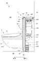
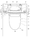
- FIG. 1 is a diagram showing a toilet cabinet 3 in a toilet room 100 according to the first embodiment.
- the toilet cabinet 3 is arranged in the toilet room 100, and the toilet body 21 of the toilet device 2 is attached to the toilet cabinet 3.
- the toilet room 100 is a substantially rectangular parallelepiped space, and the longitudinal direction extends along the front-rear direction connecting an inlet (not shown) on the front side of the toilet room 100 and a back side facing the inlet.
- the toilet room 100 includes a rear wall 101 on the back side, a pair of side walls 102 on one side and the other side in the width direction of the rear wall 101, a front wall (not shown) provided with a door for entrance and exit, and a toilet cabinet 3. And a floor surface 103 on which is provided.
- the up-down direction is the vertical direction
- the width direction is the case where the toilet cabinet 3 is viewed from the front from the entrance side of the toilet room 100 toward the rear wall 101 as shown in FIG. 1.
- the left and right means the left and right when the toilet cabinet 3 is viewed from the front.
- FIG. 2 is a side view of the toilet room 100.
- FIG. 3 is a top view of the toilet room 100.
- the toilet device 2 has a toilet body 21, a toilet lid 22, a water supply section 23, and a drain section 24.
- the toilet body 21 is a substantially U-shaped container in plan view having a bowl portion 210 in which a recessed portion having an open top is formed.
- the toilet body 21 is a main part of a toilet seated and used by a user, and a drain port for discharging dirt is formed at the bottom of the bowl 210.
- the toilet body 21 is arranged such that the lower end portion thereof is separated upward from the floor surface 103.
- the toilet body 21 is a so-called wall-mounted type, and the toilet body 21 is connected to the toilet cabinet 3 described below and installed so as to float above the floor surface 103.
- the toilet body 21 is attached at a position apart from the floor 103 by, for example, about 60 mm to 110 mm upward.
- the toilet lid 22 is a lid that covers the opening in the bowl 210 of the toilet body 21, and is opened and closed by being connected to the rear side by a hinge.
- the water supply unit 23 is a mechanism that supplies drainage water to the toilet body 21.
- the water supply unit 23 has a water supply tank 230 that is connected to a water supply pipe (not shown) provided inside the building and stores water to be supplied to the bowl unit 210.
- the drainage unit 24 has an elbow pipe 241 and a bellows pipe 242 that are connected to the toilet body 21 and drain the wastewater discharged from the drainage port of the toilet body 21 to sewage.
- the elbow pipe 241 is connected to the drain port, and the bellows pipe 242 is connected from the downstream end of the elbow pipe 241 to the sewer pipe under the floor.
- FIG. 3 is a top view of the toilet room 100.
- the counter 330 is omitted.
- the toilet cabinet 3 is arranged between the back side of the toilet body 21 and the rear wall 101 of the toilet room 100.
- the toilet cabinet 3 extends upward from the floor surface 103 beyond the upper portion of the toilet device 2 and has a depth toward the rear wall 101 side.
- the toilet cabinet 3 is a shelf that covers the water supply unit 23, the drainage unit 24, and the like in which the tank, the water stopcock, and the like of the toilet device 2 are arranged.
- the toilet cabinet 3 includes a storage unit 30, a front panel 31, a skirting board 32, a pair of frontage adjustment members 4, a pair of connecting side plates 5, a pair of lighting devices 6, a sensor 7, and a control unit ( (Not shown).
- the accommodating portion 30 is disposed between the back surface of the toilet body 21 and the rear wall 101, and accommodates components such as the water supply portion 23 and the drain portion 24 of the toilet device 2 and the power source (not shown) of the toilet device 2 inside. It is a substantially rectangular space.
- the accommodating part 30 has a frame 350 as a support part, a reinforcing tree 320, and a counter 330.
- the frame 350 is a frame body that forms a base for fixedly supporting the toilet body 21, the water supply unit 23, the drainage unit 24, and the like.
- the frame 350 has a pair of vertical rails 351, an upper rail 352, and a lower rail 353.
- the pair of vertical bars 351 is a metal frame member that extends in the up-down direction on the rear surface side of the toilet body 21 and at a position separated by a predetermined distance from the rear wall 101 to the front side.
- the pair of vertical bars 351 are arranged on one side and the other side in the width direction of the toilet body 21.
- the toilet body 21 is fixed to the vertical rail 351 via a front panel 31 described later.
- a support member 354 (see FIG.
- the upper rail 352 is an upper side of the accommodating portion 30, and the lower rail 353 is a lower side of the accommodating portion 30 and is a frame member made of metal that is laterally passed between the pair of vertical rails 351.
- the reinforcing tree 320 is a plate member directly attached to the rear wall 101, and is arranged at a position facing the frame 350 in the upper part of the housing section 30.
- the counter 330 is a rectangular plate that covers the upper part of the accommodation unit 30.
- the counter 330 is rotatably connected to the reinforcing tree 320 by a hinge, and constitutes a lid capable of opening and closing the upper opening of the accommodation unit 30.
- the front edge of the counter 330 is indirectly supported by the upper rail 352.
- the front panel 31 is connected to and supported by the vertical rail 351 of the frame 350 to which the toilet body 21 is fixed, and is attached to the back side of the toilet body 21.
- the front panel 31 is a quadrangular plate-shaped member that separates the front side of the housing portion 30 from the toilet body 21.
- the front panel 31 extends in the up-down direction from below the toilet body 21 beyond the upper end portion thereof, and constitutes the forefront portion of the toilet cabinet 3.
- the front panel 31 has an upper edge 31a extending in the width direction on the upper end side, a lower edge 31b extending in the width direction on the lower end side, and side edges 31c, 31d extending in the vertical direction on one side and the other side of the width direction.
- the dimension along the width direction of the front panel 31 is larger than the width of the toilet body 21, and the front panel 31 is arranged so as to extend from one side in the width direction of the toilet cabinet 3 to the other side.
- the side edges 31c and 31d extending in the vertical direction at the pair of side end portions of the front panel 31 are separated from the pair of side walls 102 of the toilet room 100 facing the respective side end portions. It is located at a remote location and is not a close fit to the sidewall 102. That is, the pair of side end portions of the front panel 31 are arranged apart from the pair of side walls 102 with the first gap S1.
- the first gap S1 may be, for example, about 5 mm to 40 mm, preferably about 10 mm to 35 mm.
- the front panel 31 is configured by arranging a plurality of plates adjacent to each other, and includes an upper front plate part 311, a lower right front plate part 312, a lower left front plate part 313, and a lower central front plate part. 314 and.
- the upper front plate portion 311 is a quadrangular plate member arranged on the upper portion of the front panel 31.
- the upper front plate portion 311 is fixed to the vertical rail 351.
- the lower right front plate part 312 is a rectangular plate arranged on the right side of the lower part of the front panel 31 when viewed from the front, and is arranged on the lower right side of the toilet body 21.
- the lower right front plate portion 312 is connected to the upper front plate portion 311 by the structure of the dowel and the hole, and indirectly connected to the vertical crosspiece 351 by being connected to the lower central front plate portion 314 described later. ..
- the lower left front plate part 313 is a rectangular plate arranged on the left side of the lower part of the front panel 31 in front view, and is arranged on the lower left side of the toilet body 21.
- the lower left front plate portion 313 is connected to the upper front plate portion 311 by the structure of the dowel and the hole, and is indirectly supported by the vertical crosspiece 351 by being connected to the lower central front plate portion 314 described later. ..
- the lower central front plate portion 314 is a plate arranged on the central side in the lower part of the front panel 31 when viewed from the front, and the upper side is cut out in accordance with the shape of the toilet body 21.
- the lower central front plate portion 314 is arranged on the back side of the toilet body 21 and is fixed to the vertical rail 351.
- the lower edge 31b extending along the lower edge of the front panel 31, that is, the lower edge of the lower right front plate portion 312, the lower left front plate portion 313, and the lower central front plate portion 314 is as shown in FIGS. It is arranged at a position distant upward from the floor surface 103 and is not directly connected to the floor surface 103.
- the front panel 31 is attached at a position separated from the floor surface 103 by at least 10 mm or more, preferably at a position separated by 20 mm to 50 mm, for example, about 30 mm to 40 mm.
- the skirting board 32 is an elongated plate member that is fixed to the vertical crosspiece 351 and is arranged on the back side of the lower end portion of the front panel 31 and extends from one side in the width direction of the front panel 31 to the other side.
- the skirting board 32 overlaps the back surface of the front panel 31 in the front-rear direction and abuts on the floor surface 103.
- the front surface of the skirting board 32 is in contact with the back surface of the front panel 31.
- the skirting board 32 is formed in a color tone different from that of the front panel 31, and has the same color as the side wall 102 of the toilet room 100, for example.
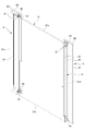
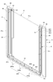
- FIG. 4 is a perspective view showing a state in which the frontage adjusting member 4, the connecting side plate 5, and the lighting device 6 are attached to the front panel 31.
- the frontage adjusting member 4 is a vertically long plate member extending along the vertical direction of the toilet cabinet 3, and has a longitudinal side edge 41, a lateral side edge 42, and an elongated hole 43.
- the longitudinal side edge 41 is arranged along the side edges 31c and 31d of the front panel 31.
- the lateral direction side edge 42 is arranged along the width direction of the front panel 31.
- the long holes 43 are formed along the lateral direction on the upper end side and the lower end side of the frontage adjusting member 4.
- a pair of frontage adjusting members 4 is arranged on the back side of the front panel 31 near the pair of side edges 31c and 31d of the front panel so as to overlap the front panel 31 in the front-rear direction.
- the frontage adjusting material 4 is attached so as to be movable in the left-right direction by adjusting the position of the screw 44 to be inserted into the long hole 43, and the outer end portion of the lateral side edge 42 of the frontage adjusting material 4 is attached to the toilet room 100.
- the side wall 102 is attached so as to be in close contact with the side wall 102.
- the frontage adjusting material 4 being “contactable” with the side wall 102 means that the frontage adjusting material 4 is in contact with the side wall 102, or even if the front side adjusting material 4 is not exactly in contact with the side wall 102 due to a construction error or the like. It means that it is possible to get close to.
- the outer end portion of the lateral direction side edge 42 of the frontage adjusting member 4 is located outside the front panel 31 in the width direction.
- the frontage adjusting member 4 is arranged rearward from the back surface of the front panel 31 and has a second gap S2 between the back surface of the front panel 31 and the back surface.
- the dimension of the second gap S2 between the back surface of the front panel 31 and the frontage adjusting member 4 is larger than the dimension of the first gap S1 between the side end portion of the front panel 31 and the side wall 102 of the toilet room 100. It is large, for example, about 40 mm to 60 mm, preferably about 45 mm to 55 mm. Since the second gap S2 is larger than the first gap S1, the independence of the front panel 31 is emphasized by the depth of the second gap S2, and the floating feeling that the front panel 31 is floating is realized. To be done.
- the frontage adjusting material 4 is composed of a color tone and a material such as white, beige, and cream that easily reflect light.
- White tones such as white, beige, and cream are more likely to reflect light than black or red tones. For this reason, it becomes easy to exhibit the function of the frontage adjusting member 4 as a reflector.
- the frontage adjusting material 4 has the lower end portion of the frontage adjusting material 4 arranged on the outer side in the width direction of the skirting board 32, and is arranged in a so-called “vertical win” with respect to the skirting board 32. ..
- the frontage adjusting material 4 and the skirting board 32 seem to be continuous when viewed from the front, and the frontage adjusting material 4 and the skirting board 32 surround the lower side of the front panel 31 in a U-shape with an upper opening. It is located in.
- connection side plate 5 is a plate that connects the back surface of the front panel 31 and the frontage adjusting member 4, and is attached so as to be substantially orthogonal to the front panel 31 and the frontage adjusting member 4.
- the connection side plate 5 is a vertically long plate member having a length substantially the same as that of the frontage adjusting member 4.
- the length of the connecting side plate 5 in the width direction corresponds to the second gap S2.
- a boss 51 projecting toward the front panel 31 side is formed on an end face of the connecting side plate 5 in the lateral direction end on the front panel 31 side, which is in contact with the front panel 31,
- the front panel 31 is inserted into and connected to holes formed at corresponding positions on the rear surface side.
- the connecting procedure of the connecting side plate 5 and the frontage adjusting member 4 will be described with reference to FIG. Since the widthwise dimension of the front panel 31 is shorter than the distance between the pair of side walls 102 of the toilet room 100, the first gap S1 opens outside the front panel 31 in the widthwise direction. Depending on the size of the first gap S1, the position of the frontage adjusting member 4 is adjusted at the construction site, either near the toilet body 21 or near the side wall 102. A screw 44 is inserted into the long hole 43 of the frontage adjusting material 4, and the frontage adjusting material 4 and the connecting side plate 5 are temporarily fastened with an L-shaped metal fitting 52.
- the front end of the lateral direction adjusting side edge 42 of the lateral direction side edge 42 (the side wall 102 side of the toilet room 100) is brought close to the side wall 102 so that the end part of the front side adjusting member 4 is moved in the left and right direction, and the position is adjusted.
- the screws 44 inserted through the upper end side and the lower end side of the member 4 are tightened to fix the pair of frontage adjusting members 4.
- a pair of lighting devices 6 are arranged slightly inside the rear side of the front panel 31 (close to the center of the front panel 31 in the width direction) so as to extend along both side edges 31c and 31d of the front panel 31.
- the lighting device 6 is attached to the connecting side plate 5 between the rear surfaces of the side edges 31c and 31d of the front panel 31 and the frontage adjusting member 4, and is viewed from the front of the toilet cabinet 3. It is placed in a position where it is not visible.
- the illuminating device 6 is an indirect illuminating device that irradiates the pair of side edges 31c and 31d of the toilet cabinet 3 with light to the pair of side walls 102 of the toilet room 100.
- the lighting device 6 includes a lighting case 61, a lighting cover 62, a lighting element, and a cable (not shown).
- the lighting case 61 is a rectangular parallelepiped case in which a lighting element and a cable are stored.
- the lighting case 61 is arranged so as to extend from one end side of the vertical side edges 31c and 31d of the front panel 31 to the other end side thereof.
- the length of the lighting case 61 is slightly shorter than the lengths of the side edges 31c and 31d of the front panel 31, and the end of the lighting case 61 is slightly inside the end of the front panel 31 in the vertical direction. Is located in.
- the lighting case 61 is arranged such that the one side edge 31c side and the other side edge 31d side of the front panel 31 are staggered in the depth direction, and the one side edge 31c side. Is attached to the connecting side plate 5 at a position distant from the back surface of the front panel 31 to the back side, and is attached to the connecting side plate 5 so as to abut the back surface of the front panel 31 on the other side edge 31d side.
- the lighting cover 62 is attached so as to cover at least the widthwise outer side of the front panel 31 in the lighting case 61 with the lighting case 61 attached.
- the lighting cover 62 is arranged so as to face the side wall 102 side of the toilet room 100.
- the lighting element is arranged inside the lighting case 61 (not shown).
- the lighting device 6 emits light when the lighting element is turned on.
- the lighting elements are arranged side by side in the vertical direction in the lighting case 61 so that the range of light emission extends in the vertical direction of the front panel 31.
- the sensor 7 is connected to the lighting device 6 as a facility device that controls the environment of the toilet room that operates based on the detection result of the sensor 7.
- the sensor 7 is a pyroelectric infrared human body detection sensor that detects a human body approaching the toilet device 2.
- the sensor 7 is attached to the front panel 31 that is the front surface of the toilet cabinet 3, and when the user enters the toilet room 100 and approaches the toilet device 2 for a predetermined distance, the human body is detected and the detection result is displayed. Output to the control unit.
- the sensor 7 is arranged on the front panel 31 which is the front surface of the toilet cabinet 3, and its detection range is set at a position where it does not interfere with the toilet lid 22 or the toilet seat when the toilet lid 22 of the toilet device 2 or the toilet seat is fully opened or fully closed. To be done. Not interfering with the toilet lid 22 or the toilet seat means that the toilet lid 22 or the toilet seat when fully opened or fully closed is not arranged within the detection range of the sensor 7. As shown in FIG. 1, in the present embodiment, the sensor 7 is arranged on the front view left side of the toilet device 2, on the outer side in the width direction of the toilet lid 22, and on the surface of the front panel 31 above the upper surface of the toilet lid 22. Has been done.
- the control unit is connected to the sensor 7 and the lighting device 6. When the sensor 7 detects a human body, the control unit turns on the lighting device 6 according to the detection result.
- the control unit is connected to a timer, and turns off the lighting device 6 when a predetermined time has elapsed after turning on the lighting device 6.
- the toilet cabinet 3 disposed on the back side of the toilet body 21 is configured to include the front panel 31 disposed on the back side of the toilet body 21 and constituting the front part of the toilet cabinet 3. ..
- the lower end portion of the front panel 31 was arranged at a position away from the floor surface 103 on which the toilet cabinet 3 was provided.
- the lower end edge 31b extending to the lower end portion of the front panel 31 is arranged at a position separated upward from the floor surface 103 on which the toilet cabinet 3 is provided, the lower side of the lower end portion of the front panel 31 is continuous from the floor surface 103. It becomes a space.
- a broom, a wiper, or the like can be slid below the front panel 31 for cleaning, which facilitates cleaning.
- separating the front panel 31 from the floor surface 103 upward it is possible to create an impression that the front panel 31 is floating from the floor surface. If the front panel 31 looks like it floats, the presence of the front panel 31 that occupies most of the front side of the toilet cabinet 3 is reduced, so the appearance of the toilet cabinet 3 is lightened and the design is improved. It is possible to provide the excellent toilet room 100.
- the front panel 31 is configured to further include a skirting board 32 that is disposed on the rear surface side of the lower end portion thereof, contacts the floor surface 103, and overlaps the rear surface of the front panel 31 in the front-rear direction.
- a skirting board 32 that is disposed on the rear surface side of the lower end portion thereof, contacts the floor surface 103, and overlaps the rear surface of the front panel 31 in the front-rear direction.
- the toilet cabinet 3 is configured to further include a frame 350 that extends at least in the vertical direction on the back side of the front panel 31 and to which the toilet body 21 is fixed, and supports the front panel 31 on the frame 350. Let By supporting the front panel 31 on at least the vertical bar 351 of the frame 350, the front panel 31 and the toilet body 21 can be easily fixed, and the workability is improved.
- the toilet body 21 is a wall-mounted toilet body. Since the toilet body 21 is arranged in a position floating above the floor surface 103 and the front panel 31 is located above the floor surface, both the toilet body 21 and the toilet cabinet 3 appear to float and float. A feeling can be produced. Since a cleaning tool such as a broom and a wiper can be moved to the lower side of the toilet body 21 during cleaning, cleaning becomes easier.
- the pair of side end portions of the front panel 31 are arranged at positions apart from the pair of side walls 102 of the facing toilet room 100, respectively. Since the side end portion of the front panel 31 is not directly joined to the side wall 102 of the toilet room 100, even if there is a gap between the front panel 31 and the side wall 102 due to a construction error or the like, the distortion is less noticeable and the workability is improved. Is improved. Since the front panel 31 is located above the floor surface 103 and above the side wall 102, the floating appearance of the front panel 31 can be further enhanced and the toilet cabinet 3 The impression on the appearance can be reduced.
- the toilet cabinet 3 arranged in the toilet room 100 and arranged on the back side of the toilet body 21 is arranged on the back side of the toilet body 21 and constitutes the front part of the toilet cabinet 3.
- the front panel 31 and the pair of lighting devices 6 extending in the vertical direction along the left and right edges of the front panel 31 are included.
- the lighting device 6 is disposed from the side edges 31c and 31d of the front panel 31 to the side wall of the toilet room 100.
- the gap S1 formed at the boundary between the side edges 31c and 31d of the front panel 31 and the side wall 102 becomes blurry and inconspicuous.
- the illuminated portion along the up-down direction of the front panel 31 becomes bright, so that the gap S1 between the side edges 31c and 31d of the front panel 31 and the side wall 102 can be made inconspicuous. Therefore, the inclination of the front panel 31 and the side wall 102 during construction becomes inconspicuous, and the appearance of the toilet room 100 becomes good. The workability is improved by making the inclination inconspicuous.
- the lighting device 6 is arranged so as to extend from one end side to the other end side of the front panel 31 in the vertical direction.
- the gap S1 between the side edges 31c and 31d of the front panel 31 and the side wall 102 becomes blurred and inconspicuous in a wide range. Therefore, the first gap S1 between the side edges 31c and 31d of the front panel 31 and the side wall 102 can be made more inconspicuous, and the same effect as described above can be obtained.
- each of the pair of side ends of the front panel 31 is arranged at a position apart from the pair of side walls 102 of the toilet room 100 facing the side ends, and the lighting device 6 is provided on the rear surface of the front panel 31.
- Light was emitted from the first gap S1 formed between the side wall 102 and the front panel 31. Since the lighting device 6 irradiates light from the first gap S1 on the back side of the front panel 31, the first gap S1 between the side end portion of the front panel 31 and the side wall 102 can be made inconspicuous. The same effect as described above is obtained.
- the lighting device 6 is arranged on the back surface of the front panel 31 at a position that is not visually recognized from the front view of the toilet cabinet 3, and is an indirect lighting device that irradiates at least a pair of side walls 102 with light. Instead of directly attaching the lighting device 6 to the pair of side walls 102, the lighting device 6 is arranged on the back side of the front panel 31 to provide indirect illumination for illuminating the side wall 102 of the toilet room 100. Since the light can be emitted within the range, the first gap S1 can be made less conspicuous.
- the toilet cabinet 3 disposed on the back side of the toilet body 21 is disposed on the back side of the toilet body 21, and includes a front panel 31 and a front panel 31 that form a front portion of the toilet cabinet 3. And a pair of frontage adjusting members 4 which are provided outside the front panel 31 in the width direction and overlap both side portions on the back side in the front-rear direction.
- the pair of side edges 31c and 31d at the pair of side end portions of the front panel 31 are arranged apart from the pair of side walls 102 of the facing toilet room 100 including the first gap S1, and the pair of frontage adjusting members 4 are provided. Were arranged apart from the back surface of the front panel 31 with a second gap.
- a first gap S1 is formed between the front panel 31 and the pair of side walls, and the frontage adjusting material 4 is arranged on the back side of the front panel 31, so that the frontage adjusting material 4 and the front panel 31 and the first gap.
- the interior of the accommodation portion 30 of the toilet room 100 can be blindfolded from S1. Since the first gap S1 is formed between the front panel 31 and the pair of side walls 102, and the second gap S2 is formed between the back surface of the front panel 31 and the frontage adjusting member 4, the front panel 31 is formed.
- the front panel is arranged independently without contacting the side wall 102 or the frontage adjusting member 4,
- the inclination that causes the formation of the gap S1 becomes inconspicuous.
- the second gap S2 is formed, the inclination becomes inconspicuous even if there is inclination during the construction of the frontage adjusting material 4. Since the inclination of the frontage adjusting material 4 and the front panel 31 becomes inconspicuous, it is possible to improve the workability while improving the appearance of the toilet cabinet 3.
- the first gap S1 allows the front panel 31 to be independently viewed in the upper front direction, and a design with a floating feeling such that the front panel 31 is floating from the floor surface 103 can be realized.
- the frontage adjusting material 4 is attached so as to be movable in the left-right direction, and is arranged so as to be able to contact the pair of side walls 102 facing each other.
- the frontage adjusting material 4 can be arranged according to the size of the first gap S1 at the construction site. Thereby, the workability is improved and the gap between the frontage adjusting member 4 and the side wall 102 can be reduced.
- the lighting device 6 is arranged between the back side of the front panel 31 and the frontage adjusting member 4.
- the first gap S1 between the front panel 31 and the side wall 102 is illuminated by the illumination and becomes less conspicuous. Since the illumination device 6 is arranged in the second gap S2, the inclination of the frontage adjusting material 4 itself is less noticeable due to illumination. Further, the illumination device 6 constitutes an indirect illumination device that illuminates between the front panel 31 and the side wall 102, and thus it is possible to produce an illumination that is softer and wider than direct light. Since the frontage adjusting material 4 has an effect as a reflection plate of illumination, when the same light source is used, the presence of the frontage adjusting material 4 produces an effect of making the illumination look brighter.
- the second gap S2 is larger than the first gap S1.
- the second gap S2 is larger than the first gap S1.
- the skirting board may be arranged on the back side of the front panel and at a position separated from the front panel to the rear side in the depth direction.
- the parts of the skirting board 32, the frontage adjusting member 4, and the illuminating device 6 which are visible in a front view are not flush with each other, but are displaced in the front-rear direction. Which of these members is located in the front or the rear may be appropriately changed.
- the shape of the toilet room 100 may be freely changed according to the building in which the toilet room is installed.
- the lighting device may be arranged between the front panel and the side wall, and may be configured as direct lighting for directly illuminating the inside of the toilet room.
- the lighting device 6 is arranged along the up-down direction on one side and the other side in the width direction of the front panel 31, but the range of the lights illuminated by the lighting device 6 may be changed as appropriate.
- the lighting element may not be continuously arranged up to the vertical end of the lighting case 61, but may be partially arranged near the center in the vertical direction.
- the lighting device 6 may be shorter than that described in the above embodiment. Even if the lighting device 6 is short, the light emitted from the lighting device 6 reaches the entire length of the front panel 31 in the vertical direction and spreads in the horizontal direction.
- the parts of the skirting board 32, the frontage adjusting material 4, and the illuminating device 6 which are viewed from the front are not flush with each other but are displaced in the front-rear direction. Which of these members is located in the front or the rear may be appropriately changed.
- the illuminating device 6 may be formed shorter than the illuminating device of the above embodiment as long as it is arranged at least at the center in the vertical direction. Even if the lighting device 6 is short, the light emitted from the lighting device 6 reaches the entire length of the front panel 31 in the vertical direction and spreads in the horizontal direction.
- the lighting device 6 is arranged at least in the vertical center of the front panel 31, so that at least the central portion of the front panel 31 in the vertical direction is illuminated. If the central portion is illuminated, it is difficult for a person to pay attention to the vertical end portions thereof, so that the gap S1 between the side edges 31c and 31d of the front panel 31 and the side wall 102 can be made inconspicuous. Therefore, even if the lighting device 6 is shortened, the same effect as described above can be obtained. It is possible to reduce the number of lighting devices 6 and the number of lighting elements that are internal light sources, and increase the degree of freedom in designing the lighting devices 6.
- the illuminating device 6 only needs to be able to emit light from the first gap S1 formed between each of the pair of side walls 102 and the front panel 31, and may be attached to the frontage adjusting material 4 and other members. .. Even if the illuminating device is arranged on the front side of the front panel on the inner side in the width direction with respect to the pair of side edges, it is within the scope of the present disclosure as long as it is along both left and right edges of the front panel.
- the lighting device between the front panel and the side wall and configure it as direct lighting that directly illuminates the inside of the toilet room.
- the parts of the skirting board 32, the frontage adjusting member 4, and the lighting device 6 that are visible from the front are not flush with each other, but are displaced in the front-back direction. Which of these members is located in the front or the rear may be appropriately changed.
- the frontage adjusting material may be a member continuous with the connecting side plate.
- the lighting device may be arranged between the front panel and the side wall, and may be configured as direct lighting for directly illuminating the inside of the toilet room.
- the second gap S2 is configured to be larger than the first gap S1.
- the second gap S2 may be smaller than the first gap.
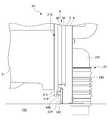
- FIG. 5 is an enlarged side view showing the vicinity of the lower ends of the front panel 31A and the skirting board 32A in the toilet cabinet 3A according to the second embodiment.
- a lower illumination device 600 may be provided between the back surface of the front panel 31A and the skirting board 32A.
- the lower lighting device 600 is arranged along the width direction of the lower edge of the front panel 31A. More specifically, the rear side of the lower end of the front panel 31A is cut out in an L shape in a side view to form a cutout 319. A space is formed between the notch 319 at the lower end of the front panel 31A and the skirting board 32A, and the lower lighting device 600 that illuminates downward is arranged in this space.
- the light emitted from the lower illuminating device 600 and the light emitted from the illuminating device 6 of the above-described embodiment overlap at the widthwise outer corner of the lower end portion of the front panel 31A.
- the lower illumination device 600 and the illumination device 6 are arranged so as to continuously surround the lower periphery of the front panel 31A. From this, it becomes easy to visually recognize that the front panel is in a state of floating from the floor surface 103.
- the lower lighting device 600 may be an indirect lighting device that irradiates the floor surface 103 of the toilet room 100 with light from the lower edge 31b side of the toilet cabinet 3. Another lighting device for the lower side may be arranged between the front panel and the floor surface and configured as direct lighting for directly illuminating the inside of the toilet room.
- a toilet space 1000 according to the third embodiment of the present disclosure will be described with reference to FIGS. 1 and 6 to 9.
- common configurations to the first and second embodiments will be described using common reference numerals.
- FIG. 1 is a diagram showing a toilet cabinet 3 in a toilet space 1000 according to this embodiment.
- the toilet cabinet 3 is arranged on the back side of the toilet body 21 of the toilet device 2 in the toilet space 1000.
- the toilet space 1000 is a substantially rectangular space, and the longitudinal direction extends along the front-rear direction connecting an inlet (not shown) on the front side of the toilet space 1000 and a back side facing the inlet.
- the toilet space 1000 includes a rear wall 101 on the back side, a pair of side walls 102 on one side and the other side in the width direction of the rear wall 101, a front wall (not shown) provided with a door for entrance and exit, and a toilet cabinet 3. And a floor surface 103 on which is provided.
- the up-down direction is the vertical direction
- the width direction is the case where the toilet cabinet 3 is viewed from the front from the entrance side of the toilet space 1000 toward the rear wall 101 as shown in FIG.
- the left and right means the left and right when the toilet cabinet 3 is viewed from the front.
- FIG. 6 is a side view of the toilet space 1000.
- FIG. 7 is a top view of the toilet space 1000.
- the toilet device 2 has a toilet body 21, a toilet lid 22, a water supply section 23, and a drain section 24.
- the toilet body 21 is a substantially U-shaped container in plan view having a bowl portion 210 in which a recessed portion having an open top is formed.
- the toilet body 21 is a main part of a toilet seated and used by a user, and a drain port for discharging dirt is formed at the bottom of the bowl 210.
- the toilet body 21 is arranged such that the lower end portion thereof is separated upward from the floor surface 103.
- the toilet body 21 is a so-called wall-mounted type, and the toilet body 21 is connected to the toilet cabinet 3 described below and installed so as to float above the floor surface 103.
- the toilet body 21 is attached at a position apart from the floor 103 by, for example, about 60 mm to 110 mm upward.
- the toilet lid 22 is a lid that covers the opening in the bowl 210 of the toilet body 21, and is opened and closed by being connected to the rear side by a hinge.
- the water supply unit 23 is a mechanism that supplies drainage water to the toilet body 21.
- the water supply unit 23 has a water supply tank 230 that is connected to a water supply pipe (not shown) provided inside the building and stores water to be supplied to the bowl unit 210.
- the drainage unit 24 has an elbow pipe 241 and a bellows pipe 242 that are connected to the toilet body 21 and drain the wastewater discharged from the drainage port of the toilet body 21 to sewage.
- the elbow pipe 241 is connected to the drain port, and the bellows pipe 242 is connected from the downstream end of the elbow pipe 241 to the sewer pipe under the floor.
- FIG. 7 is a top view of the toilet space 1000.
- the counter 330 is omitted.
- the toilet cabinet 3 is arranged between the back side of the toilet body 21 and the rear wall 101 of the toilet space 1000, as shown in FIGS. 1, 6, and 7.
- the toilet cabinet 3 extends upward from the floor surface 103 beyond the upper portion of the toilet device 2 and has a depth toward the rear wall 101 side.
- the toilet cabinet 3 is a shelf that covers the water supply unit 23, the drainage unit 24, and the like in which the tank, the water stopcock, and the like of the toilet device 2 are arranged.
- the toilet cabinet 3 includes a storage unit 30, a front panel 31, a skirting board 32, a pair of frontage adjustment members 4, a pair of connecting side plates 5, a pair of lighting devices 6, a sensor 7, and a control unit ( (Not shown).
- the accommodating portion 30 is disposed between the back surface of the toilet body 21 and the rear wall 101, and accommodates components such as the water supply portion 23 and the drain portion 24 of the toilet device 2 and the power source (not shown) of the toilet device 2 inside. It is a substantially rectangular space.
- the accommodating part 30 has a frame 350 as a support part, a reinforcing tree 320, and a counter 330.
- the frame 350 is a frame body that forms a base for fixedly supporting the toilet body 21, the water supply unit 23, the drainage unit 24, and the like.
- the frame 350 has a pair of vertical rails 351, an upper rail 352, and a lower rail 353.
- the pair of vertical bars 351 is a metal frame member that extends in the up-down direction on the rear surface side of the toilet body 21 and at a position separated by a predetermined distance from the rear wall 101 to the front side.
- the pair of vertical bars 351 are arranged on one side and the other side in the width direction of the toilet body 21.
- the toilet body 21 is fixed to the vertical rail 351 via a front panel 31 described later.
- a support member 354 (see FIG.
- the upper rail 352 is an upper side of the accommodating portion 30, and the lower rail 353 is a lower side of the accommodating portion 30 and is a frame member made of metal that is laterally passed between the pair of vertical rails 351.
- the reinforcing tree 320 is a plate member directly attached to the rear wall 101, and is arranged at a position facing the frame 350 in the upper part of the housing section 30.
- the counter 330 is a rectangular plate that covers the upper part of the accommodation unit 30.
- the counter 330 is rotatably connected to the reinforcing tree 320 by a hinge, and constitutes a lid capable of opening and closing the upper opening of the accommodation unit 30.
- the front edge of the counter 330 is indirectly supported by the upper rail 352.
- the front panel 31 is connected to and supported by the vertical rail 351 of the frame 350 to which the toilet body 21 is fixed, and is attached to the back side of the toilet body 21.
- the front panel 31 is a quadrangular plate-shaped member that separates the front side of the housing portion 30 from the toilet body 21.
- the front panel 31 extends in the up-down direction from below the toilet body 21 beyond the upper end portion thereof, and constitutes the forefront portion of the toilet cabinet 3.
- the front panel 31 has an upper end edge 31a extending in the width direction on the upper end side, a lower end edge 31b extending in the width direction on the lower end side, side edges 31c and 31d extending in the up and down direction on one side and the other side in the width direction, and a cutout portion. 319 and.
- the dimension along the width direction of the front panel 31 is larger than the width of the toilet body 21, and the front panel 31 is arranged so as to extend from one side in the width direction of the toilet cabinet 3 to the other side.
- the side edges 31c and 31d extending in the vertical direction at the pair of side end portions of the front panel 31 are separated from the pair of side walls 102 of the toilet space 1000 facing the respective side end portions. It is located at a remote location and is not a close fit to the sidewall 102. That is, the pair of side end portions of the front panel 31 are arranged apart from the pair of side walls 102 with the first gap S1.
- the first gap S1 may be, for example, about 5 mm to 40 mm, preferably about 10 mm to 35 mm.
- the front panel 31 is configured by arranging a plurality of plates adjacent to each other, and includes an upper front plate part 311, a lower right front plate part 312, a lower left front plate part 313, and a lower central front plate part. 314 and.
- the upper front plate portion 311 is a quadrangular plate member arranged on the upper portion of the front panel 31.
- the upper front plate portion 311 is fixed to the vertical rail 351.
- the lower right front plate part 312 is a rectangular plate arranged on the right side of the lower part of the front panel 31 when viewed from the front, and is arranged on the lower right side of the toilet body 21.
- the lower right front plate portion 312 is connected to the upper front plate portion 311 by the structure of the dowel and the hole, and indirectly connected to the vertical crosspiece 351 by being connected to the lower central front plate portion 314 described later. ..
- the lower left front plate part 313 is a rectangular plate arranged on the left side of the lower part of the front panel 31 in front view, and is arranged on the lower left side of the toilet body 21.
- the lower left front plate portion 313 is connected to the upper front plate portion 311 by the structure of the dowel and the hole, and is indirectly supported by the vertical crosspiece 351 by being connected to the lower central front plate portion 314 described later. ..
- the lower central front plate portion 314 is a plate arranged on the central side in the lower part of the front panel 31 when viewed from the front, and the upper side is cut out in accordance with the shape of the toilet body 21.
- the lower central front plate portion 314 is arranged on the back side of the toilet body 21 and is fixed to the vertical rail 351.
- the front panel 31 has a lower end edge 31b extending along a lower end thereof, that is, a lower right front plate portion 312, a lower left front plate portion 313, and a lower central front plate portion 314 at lower end edges.
- the back side has a cutout portion 319 cut out in an L shape in a side view.
- the notch 319 is formed such that the thickness in the side view is thinner than the thickness on the upper edge 31a side from one side to the other in the width direction on the back side of the lower edge 31b.
- the lower end edge 31 b is arranged at a position separated upward from the floor surface 103 and is not directly connected to the floor surface 103.
- the front panel 31 is attached at a position separated from the floor surface 103 by at least 10 mm or more, preferably at a position separated by 20 mm to 50 mm, for example, about 30 mm to 40 mm.
- the skirting board 32 is an elongated plate member which is fixed to the vertical crosspiece 351 and is arranged on the back side of the lower end portion of the front panel 31 and extends from one side in the width direction of the front panel 31 to the other side.
- the skirting board 32 overlaps the back surface of the front panel 31 in the front-rear direction and abuts on the floor surface 103.
- a space is formed between the skirting board 32 and the back surface of the front panel 31 by a notch portion 319 formed in the lower end edge 31b of the front panel 31.
- the skirting board 32 is formed in a color tone different from that of the front panel 31, and has the same color as the side wall 102 of the toilet space 1000, for example.
- FIG. 8 is a perspective view of the front panel 31 to which the frontage adjusting member 4, the connecting side plate 5, and the lighting device 6 are attached.
- the frontage adjusting member 4 is a vertically long plate member extending along the vertical direction of the toilet cabinet 3, and has a longitudinal side edge 41, a lateral side edge 42, and an elongated hole 43.
- the longitudinal side edge 41 is arranged along the side edges 31c and 31d of the front panel 31.
- the lateral direction side edge 42 is arranged along the width direction of the front panel 31.
- the long holes 43 are formed along the lateral direction on the upper end side and the lower end side of the frontage adjusting member 4.
- a pair of frontage adjusting members 4 are arranged near the pair of side edges 31c and 31d of the front panel 31 so as to overlap the front panel 31 in the front-rear direction.
- the frontage adjusting material 4 is attached so as to be movable in the left-right direction by adjusting the position of a screw 44 to be inserted into the long hole 43, and the outer end portion of the lateral direction side edge 42 of the frontage adjusting material 4 is attached to the toilet space 1000.
- the side wall 102 is attached so as to be in close contact with the side wall 102.
- the frontage adjusting material 4 can be brought close enough to contact the frontage adjusting material 4 even if the frontage adjusting material 4 is brought into contact with the side wall 102 or is not exactly brought into contact with the side wall 102 due to a construction error or the like.
- the outer end portion of the lateral direction side edge 42 of the frontage adjusting member 4 is located outside the front panel 31 in the width direction.
- the frontage adjusting member 4 is arranged rearward from the back surface of the front panel 31 and has a second gap S2 between the back surface of the front panel 31 and the back surface.
- the dimension of the second gap S2 between the back surface of the front panel 31 and the frontage adjusting material 4 is larger than the dimension of the first gap S1 between the side end portion of the front panel 31 and the side wall 102 of the toilet space 1000. It is large, for example, about 40 mm to 60 mm, preferably about 45 mm to 55 mm. Since the second gap S2 is larger than the first gap S1, the independence of the front panel 31 is emphasized by the depth of the second gap S2, and the floating feeling that the front panel 31 is floating is realized. To be done.
- the frontage adjusting material 4 is composed of a color tone and a material such as white, beige, and cream that easily reflect light.
- White tones such as white, beige, and cream are more likely to reflect light than black or red tones. For this reason, it becomes easy to exhibit the function of the frontage adjusting member 4 as a reflector.
- the frontage adjusting material 4 has the lower end portion of the frontage adjusting material 4 arranged on the outer side in the width direction of the skirting board 32, and is arranged in a so-called “vertical win” with respect to the skirting board 32. ..
- the frontage adjusting material 4 and the skirting board 32 seem to be continuous when viewed from the front, and the frontage adjusting material 4 and the skirting board 32 surround the lower side of the front panel 31 in a U-shape with an upper opening. It is located in.
- connection side plate 5 is a plate that connects the back surface of the front panel 31 and the frontage adjusting member 4, and is attached so as to be substantially orthogonal to the front panel 31 and the frontage adjusting member 4.
- the connection side plate 5 is a vertically long plate member having a length substantially the same as that of the frontage adjusting member 4.
- the length of the connecting side plate 5 in the width direction corresponds to the second gap S2.
- a boss 51 projecting toward the front panel 31 side is formed on an end face of the connecting side plate 5 in the lateral direction on the front panel 31 side, which is in contact with the front panel 31,
- the front panel 31 is inserted into and connected to holes formed at corresponding positions on the rear surface side.
- the connecting procedure of the connecting side plate 5 and the frontage adjusting member 4 will be described with reference to FIG. Since the widthwise dimension of the front panel 31 is shorter than the distance between the pair of side walls 102 of the toilet space 1000, the first gap S ⁇ b>1 opens outside the front panel 31 in the widthwise direction. Depending on the size of the first gap S1, the position of the frontage adjusting member 4 is adjusted at the construction site, either near the toilet body 21 or near the side wall 102. A screw 44 is inserted into the long hole 43 of the frontage adjusting material 4, and the frontage adjusting material 4 and the connecting side plate 5 are temporarily fastened with an L-shaped metal fitting 52.
- the front end of the lateral direction adjusting side edge 42 of the lateral direction edge 42 (on the side wall 102 side of the toilet space 1000) is moved close to the side wall 102 so as to come into contact with the side wall 102, and the position is adjusted.
- the screws 44 inserted through the upper end side and the lower end side of the member 4 are tightened to fix the pair of frontage adjusting members 4.
- the lighting device 6 includes a vertical lighting device 63 provided along both side edges 31c and 31d of the front panel 31, and a lower lighting device 64 provided along a lower edge 31b of the front panel. And a control unit 60 (see FIG. 7) that controls turning on and off of the lighting device 6.
- a pair of the vertical lighting devices 63 is arranged slightly inside the rear side of the front panel 31 (close to the center of the front panel 31 in the width direction) so as to extend along both side edges 31c and 31d of the front panel 31.
- the vertical lighting device 63 is attached to the connection side plate 5 between the rear surfaces of the side edges 31c and 31d of the front panel 31 and the frontage adjusting member 4, and the front surface of the toilet cabinet 3. It is placed at a position that is not visually recognized.
- the vertical lighting device 63 is an indirect lighting device that irradiates the pair of side edges 102 of the toilet cabinet 1000 with light from the pair of side edges 31c and 31d of the toilet cabinet 3.
- the vertical lighting device 63 includes a lighting case 631, a lighting cover 632, a lighting element 633, and a cable (not shown).
- the lighting case 631 is a rectangular parallelepiped case in which the lighting element 633 and a cable are housed.
- the lighting case 631 is arranged so as to extend from one end side of the vertical side edges 31c and 31d of the front panel 31 to the other end side thereof.
- the length of the lighting case 631 is slightly shorter than the length of the side edges 31c and 31d of the front panel 31, and the end of the lighting case 631 is slightly inside the end of the front panel 31 in the vertical direction. Is located in.
- the lighting case 631 is arranged such that the one side edge 31c side and the other side edge 31d side of the front panel 31 are staggered in the depth direction, and the one side edge 31c side is disposed. Is attached to the connecting side plate 5 at a position distant from the back surface of the front panel 31 to the back side, and is attached to the connecting side plate 5 so as to abut the back surface of the front panel 31 on the other side edge 31d side.
- the lighting cover 632 is attached so as to cover at least the widthwise outer side of the front panel 31 in the lighting case 631 with the lighting case 631 attached.
- the lighting cover 632 is arranged so as to face the side wall 102 side of the toilet space 1000.
- a plurality of lighting elements 633 are arranged inside the lighting case 631 with a space between each other.
- the vertical lighting device 63 emits light when the lighting element 633 is turned on.
- the lighting elements 633 are arranged side by side along the vertical direction in the lighting case 631 so that the emission range extends in the vertical direction of the front panel 31.
- the lower lighting device 64 is arranged on the rear side of the front panel 31 and slightly above the lower end thereof so as to extend along the lower edge 31b of the front panel 31. That is, the lower lighting device 64 is arranged on both sides of the front panel 31 in the width direction and both sides of the central portion.
- the lower lighting device 64 is arranged in a space between the cutout portion 319 of the lower end edge 31b of the front panel 31 and the skirting board 32, and is attached to the skirting board 32.
- the lower lighting device 64 is arranged at a position that is not visually recognized in the front view of the toilet cabinet 3.
- the lower lighting device 64 is an indirect lighting device that irradiates the floor surface 103 of the toilet space 1000 with light from the lower end edge 31b side of the toilet cabinet 3.
- the lower lighting device 64 includes a lighting case 641, a lighting cover 642, a lighting element 643 as a lighting element of the present disclosure, and a cable (not shown).
- the lighting case 641 is a rectangular parallelepiped case in which a lighting element 643 and a cable are stored inside.
- the lighting case 641 is arranged so as to extend from one end side of the lower edge 31b of the front panel 31 in the width direction to the other end side.
- the length of the lighting case 641 is slightly shorter than the length of the lower end edge 31b of the front panel 31, and the end of the lighting case 641 is located slightly inside the end of the front panel 31 in the width direction. is doing.
- the lighting cover 642 is attached so as to cover at least the outside (lower side) of the front panel 31 in the lighting case 641 with the lighting case 641 attached.
- the lighting cover 642 is arranged so as to face the floor surface 103 side of the toilet space 1000.
- a plurality of lighting elements 643 are arranged inside the lighting case 641 and are spaced from one another in the width direction inside the lighting case 641 to the other. When the lighting element 643 is turned on, the lower lighting device 64 emits light.
- the lighting element 643 is arranged so that the light emission range extends over the entire area of the front panel 31 in the width direction.
- the lighting element 643 has a plurality of outer lighting elements 643a arranged on both outer sides in the width direction and a plurality of center side lighting elements 643b arranged on the central portion side in the width direction.
- the light of the illumination device 6 is arranged so that the lower illumination device 64 and the vertical illumination device 63 continuously surround the lower periphery of the front panel 31. From this, it becomes easy to visually recognize that the front panel is in a state of floating from the floor surface 103.
- the control unit 60 switches ON/OFF of the vertical lighting device 63 and the lower lighting device 64. Therefore, it is possible to select to turn on only the vertical lighting device 63 and the lower lighting device 64, or to turn on both the vertical lighting device 63 and the lower lighting device 64.
- the control unit 60 controls the lighting element 633 of the vertical lighting device 63, the outer lighting element 643a and the central lighting element 643b of the lower lighting device 64 to be turned on and off.
- the control unit 60 switches between lighting the lighting elements 643 only on both outer sides in the width direction or lighting the entire area from one side to the other side in the width direction.
- the outer side lighting element 643a and the center side lighting element 643b of the lower lighting device 64 only the outer side lighting element 643a is turned on when only the two outer sides in the width direction are turned on, and the outer side lighting element 643a is turned on when the entire width direction is turned on. Both 643a and the central lighting element 643b are turned on.
- the control unit 60 has a timer, and turns off the lighting device 6 when a predetermined time elapses after the lighting device 6 is turned on.
- the sensor 7 is connected to the lighting device 6.
- the sensor 7 is a pyroelectric infrared human body detection sensor that detects a human body approaching the toilet device 2.
- the sensor 7 is attached to the front panel 31, detects the human body when the user enters the toilet space 1000 and approaches the toilet device 2 by a predetermined distance, and outputs the detection result to the control unit 60.
- the sensor 7 is arranged on the front panel 31, which is the front surface of the toilet cabinet 3, and its detection range is set at a position where it does not interfere with the toilet lid 22 or the toilet seat when the toilet lid 22 of the toilet device 2 or the toilet seat is fully closed. ..
- the sensor 7 is arranged on the front view left side of the toilet device 2, on the outer side in the width direction of the toilet lid 22, and on the surface of the front panel 31 above the upper surface of the toilet lid 22. Has been done.
- the toilet cabinet 3 disposed on the back side of the toilet body 21 is disposed on the back side of the toilet body 21, and includes a front panel 31 and a front panel 31 that form a front portion of the toilet cabinet 3. And a lighting device 6 arranged at least on both sides in the width direction in a front view.
- the toilet cabinet 3 has the wall-mounted toilet body 21 or the floor-standing toilet body 21A, if the lighting devices 6 are arranged at least on both sides in the width direction in the front view of the front panel 31, It becomes possible to illuminate the periphery of the toilet body in the toilet cabinet 3 regardless of the shape or configuration of the toilet body 21. Therefore, the toilet cabinet 3 with a highly versatile lighting device can be provided.
- the toilet body 21 is a wall-mounted toilet body whose lower end is located above the lower edge 31b of the front panel 31.
- the lighting device 6 is arranged in the center portion of the front panel 31 in the width direction. By arranging the lighting elements 643 in the lower lighting device 64 on both sides in the width direction and further in the central portion in the width direction, it is possible to illuminate one side to the other side of the front panel 31 in the width direction.
- the toilet body 21 is a wall-mounted type, the lower side of the toilet body 21 can be entirely illuminated.
- the lighting device 6 is provided with a plurality of lighting elements 643 arranged from one side to the other in the width direction of the front panel 31 with a space therebetween, and the lighting element 643 is arranged in the center of the lower lighting device 64 in the width direction. It is configured to include a control unit 60 that switches on and off between the unit and both outer sides. The control unit can switch on and off independently of each other on the outer side and the central side of the lower illumination device 64 in the width direction.
- the outer lighting elements 643a on both sides in the width direction of the lower lighting device 64 may be turned on, or the outer lighting elements 643a and the outer lighting elements 643a may be placed on the center side in the width direction.
- Both of the plurality of center side lighting elements 643b arranged can be turned on, and the illuminated portion along the width direction of the front panel 31 can be freely changed.
- a skirting board 32 that is disposed on the rear surface side of the lower end portion of the front panel 31 and that contacts the floor surface 103 on which the toilet cabinet 3 is disposed and that overlaps the rear surface of the front panel 31 in the front-rear direction is further included.
- the lower illumination device 64 is arranged between the back surface of the front panel 31 and the skirting board 32.
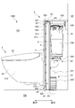
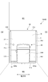
- FIG. 9 shows a toilet cabinet 3B in a toilet space 1000B according to the fourth embodiment.
- the toilet body 21 is a wall-hanging type in which the lower end portion is located above the lower edge of the front panel 31 has been described as an example, but as shown in FIG. It may be a floor-standing type in which the cabinet 3 is placed on the floor surface 103.
- the lighting devices are arranged at the bottom of the front panel 31 at least on both sides in the width direction in a front view.
- the lower lighting device 64 only the outer lighting elements 643a on both outer sides in the width direction of the toilet body 21B are turned on.
- the lower illumination device 64 may be the same as the one attached to the front panel 31 on the back side of the wall-mounted toilet body, and only the outer illumination element 643a may be turned on. Therefore, there is no need to prepare a toilet cabinet in which the lower lighting device 64 is arranged differently between the wall-mounted type and the floor-standing type, and product management becomes easy. The number of parts can be reduced, and the manufacturing cost can be reduced.
- the outer lighting element 643a it is possible to illuminate the lower side surface of the floor-standing toilet body 21B with lighting.
- the vertical lighting device 63 and the lower lighting device 64 may be arranged between the front panel and the side wall to constitute direct lighting for directly illuminating the inside of the toilet room.
- Toilet cabinet 4 Frontage adjustment material 6 Lighting device 21 Toilet body 31 Front panel (front part) 31b Lower end edge 32 Baseboard 60 Control part 100 Toilet room 1000 Toilet space 102 A pair of side walls 103 Floor surface 350 Frame (supporting part) 643 Illumination element S1 1st gap S2 2nd gap
Landscapes
- Health & Medical Sciences (AREA)
- Public Health (AREA)
- Engineering & Computer Science (AREA)
- General Engineering & Computer Science (AREA)
- Life Sciences & Earth Sciences (AREA)
- Hydrology & Water Resources (AREA)
- Water Supply & Treatment (AREA)
- Epidemiology (AREA)
- General Health & Medical Sciences (AREA)
- Toilet Supplies (AREA)
- Residential Or Office Buildings (AREA)
Abstract
掃除が容易なトイレ用キャビネットを提供すること。 便器本体21の背面側に配置されるトイレ用キャビネット3であって、便器本体21の背面側に配置され、トイレ用キャビネット3の前面部を構成する前パネル31を備え、前パネル31の下端部は、トイレ用キャビネット3が設けられる床面103から離れた位置に配置される、トイレ用キャビネット3である。トイレ用キャビネット3は、前パネル31の下端部の背面側に配置され、床面103と当接し、前パネル31の背面と前後方向で重なる巾木32をさらに備えることが好ましい。
Description
本開示は、トイレ用キャビネットに関する。
従来、トイレルーム内に配置され、便器本体の背面側に配置されるトイレ用キャビネットが知られている。トイレ用キャビネットには、トイレルームの床面から所定高さ延び、便器本体が接続される板状の前パネルが設けられている(例えば、特許文献1参照)。
トイレ用キャビネットは、トイレルームの便器本体を挟んで対向する一対の側壁の間で、トイレ用キャビネットの幅が、トイレルームの一対の側壁の間の全幅に亘るように配置されている(例えば、特許文献2参照)。特許文献1に記載のトイレ用キャビネットには、夜間にトイレルームを使用する場合に使用者の足元を照らすため、トイレ用キャビネットの内部に照明装置が設置されている。
従来、便器本体の背面にトイレ用キャビネットを配置し、トイレ用キャビネットの前面パネルに照明装置を取り付けて、夜間等のために便器本体の下面側を照らすように構成したトイレ用キャビネットが提案されている(例えば、特許文献2参照)。特許文献1に記載の技術では、便器本体は、トイレ用キャビネットに取り付けられた壁掛け式であり、照明装置は、便器本体の下端近傍で、前面パネルの幅方向の中央部に配置されている。
トイレルーム内の便器本体の背面側は、手が届きにくく人も通行しない。トイレ用キャビネットの下端側には、トイレ用キャビネットに飛散した水が垂れ落ちたりし、汚れやすい。このため、掃除が容易で汚れにくいトイレ用キャビネットが望まれていた。
トイレルーム等を含む建築物は、施工時の誤差や周囲環境によって歪みが生じている場合があり、トイレルームの側壁の間にトイレ用キャビネットを配置しようとする際に、トイレルームの側壁とトイレ用キャビネットの側端部との間に隙間が生じ、建築物の歪みが目立ってしまうことがあった。そこで、この歪みが目立ちにくいトイレ用キャビネットが望まれていた。
便器本体は、施工されるトイレ空間によって、壁掛け式の場合もあれば、床置き式の場合もある。照明装置が前パネルに取り付けられて、便器本体の下端近傍に取り付けられている場合、壁掛け式と床置き式の場合とで照明装置の配置の異なるトイレ用キャビネットを用意する必要があった。このため、製品管理が煩雑になっていた。
本開示は、便器本体(例えば、後述の便器本体21)の背面側に配置されるトイレ用キャビネット(例えば、後述のトイレ用キャビネット3)であって、前記便器本体の背面側に配置され、前記トイレ用キャビネットの前面部を構成する前パネル(例えば、後述の前パネル31)を備え、前記前パネルの下端部は、トイレ用キャビネットが設けられる床面(例えば、後述の床面103)から離れた位置に配置される、トイレ用キャビネットに関する。
本開示は、便器本体(例えば、後述の便器本体21)の背面側に配置されるトイレ用キャビネット(例えば、後述のトイレ用キャビネット3)であって、前記便器本体の背面側に配置され、前記トイレ用キャビネットの前面部を構成する前パネル(例えば、後述の前パネル31)と、前記前パネルの左右両側縁に沿って上下方向に延びる一対の照明装置(例えば、後述の照明装置6)と、を備える、トイレ用キャビネットに関する。
本開示は、便器本体(例えば、後述の便器本体21)の背面側に配置されるトイレ用キャビネット(例えば、後述のトイレ用キャビネット3)であって、前記便器本体の背面側に配置され、前記トイレ用キャビネットの前面部を構成する前パネル(例えば、後述の前パネル31)と、前記前パネルの背面側の両側端部と前後方向に重なるとともに前記前パネルより幅方向の外側に設けられる一対の間口調整材(例えば、後述の間口調整材4)と、を備え、前記前パネルの一対の側端部はそれぞれ、対向するトイレルーム(例えば、後述のトイレルーム100)の一対の側壁から離れて第1の隙間(例えば、後述の第1の隙間S1)を有して配置され、前記一対の間口調整材はそれぞれ、前記前パネルの背面から離れて第2の隙間(例えば、後述の第2の隙間S2)を有して配置される、トイレ用キャビネットに関する。
本開示は、便器本体(例えば、後述の便器本体21)の背面側に配置されるトイレ用キャビネット(例えば、後述のトイレ用キャビネット3)であって、前記便器本体の背面側に配置され、前記トイレ用キャビネットの前面部を構成する前パネル(例えば、後述の前パネル31)と、前記前パネルの下部で正面視における少なくとも幅方向両側に配置される照明装置(例えば、後述の照明装置6)と、を備えるトイレ用キャビネットに関する。
以下、本開示の第1実施形態について、図面を参照しながら詳細に説明する。
図1は、第1実施形態におけるトイレルーム100内のトイレ用キャビネット3を示す図である。トイレ用キャビネット3は、トイレルーム100内に配置されるとともに、便器装置2の便器本体21が取り付けられる。
図1は、第1実施形態におけるトイレルーム100内のトイレ用キャビネット3を示す図である。トイレ用キャビネット3は、トイレルーム100内に配置されるとともに、便器装置2の便器本体21が取り付けられる。
トイレルーム100は、図1に示すように、略直方形の空間であり、長手方向がトイレルーム100の手前側の入口(図示省略)と入口に対向する奥側とを結ぶ前後方向に沿っている。トイレルーム100は、奥側の後壁101と、後壁101の幅方向の一方及び他方の一対の側壁102と、出入口用の扉が設けられた前壁(図示省略)と、トイレ用キャビネット3が設けられる床面103と、を有する。本明細書において、上下方向とは天地方向であり、幅方向とは、図1に示すように、トイレルーム100の入口側から後壁101に向かって、トイレ用キャビネット3を正面から見た場合の左右を結ぶ横方向を意味する。左右とは、トイレ用キャビネット3を正面から見た場合の左右を意味する。
図2は、トイレルーム100の側面図である。図3は、トイレルーム100の上面図である。便器装置2は、図2に示すように、便器本体21と、便蓋22と、給水部23と、排水部24と、を有する。
便器本体21は、上部が開口した凹部が形成されたボウル部210を有する平面視略U字状の容器である。便器本体21は、使用者が着座して使用する便器を構成する主要部分であり、ボウル部210の底部には汚物を排出する排水口が形成されている。便器本体21は、下端部が床面103から上方に離れた位置に配置されている。便器本体21は、いわゆる壁掛け式であり、便器本体21が後述するトイレ用キャビネット3に接続されて、床面103から宙に浮いたように設置されている。便器本体21は、床面103から、例えば60mm~110mm程度上方に離れた位置に取り付けられている。
便蓋22は、便器本体21のボウル部210における開口を覆う蓋であり、後方側にヒンジで接続されて開閉される。給水部23は、便器本体21に排水用の水を供給する機構である。給水部23は、建物の内部に設けられた給水管(図示省略)に接続され、ボウル部210に供給する水を貯水する給水タンク230を有する。排水部24は、便器本体21に接続され、便器本体21の排水口から排出される汚水を下水へ排水するエルボ管241及び蛇腹管242を有する。エルボ管241は、排水口に接続されており、蛇腹管242は、エルボ管241の下流側端部から床下の下水管へと接続される。
図3は、トイレルーム100の上面図である。図3では、カウンター330を省略して示している。トイレ用キャビネット3は、図1~図3に示すように、便器本体21の背面側と、トイレルーム100の後壁101との間に配置される。トイレ用キャビネット3は、床面103から便器装置2の上部を越えて上方へ延びるとともに、後壁101側へ奥行を有する。トイレ用キャビネット3は、便器装置2のタンクや止水栓等が配置される給水部23や排水部24等を覆い隠す棚である。トイレ用キャビネット3は、収容部30と、前パネル31と、巾木32と、一対の間口調整材4と、一対の連結側板5と、一対の照明装置6と、センサ7と、制御部(図示省略)と、を有する。
収容部30は、便器本体21の背面と後壁101との間に配置され、便器装置2の給水部23や排水部24、便器装置2の電源(図示省略)等の構成部を内部に収容する略直方形の空間である。収容部30は、支持部としてのフレーム350と、補強木320と、カウンター330と、を有する。
フレーム350は、図1に示すように、便器本体21、給水部23及び排水部24等を固定支持する土台を形成する枠体である。フレーム350は、一対の縦桟351、上桟352、及び下桟353を有する。一対の縦桟351は、便器本体21の背面側で、後壁101から前方側に所定距離離れた位置に、上下方向に延びる金属製の枠材である。一対の縦桟351は、便器本体21の幅方向の一方及び他方に配置される。縦桟351には、後述する前パネル31を介して便器本体21が固定される。一対の縦桟351の間に、横方向に延びる支持部材354(図2参照)が取り付けられ、給水タンク230が支持部材354に固定支持される。上桟352は収容部30の上部側で、下桟353は収容部30の下部側で、一対の縦桟351の間に横方向に渡される金属製の枠材である。
補強木320は、後壁101に直接取り付けられる板材であり、収容部30の上部でフレーム350に対向する位置に配置される。
カウンター330は、収容部30の上部を覆う長方形の板である。カウンター330は補強木320に回動可能にヒンジで接続され、収容部30の上部開口を開閉可能な蓋を構成する。カウンター330の手前側の縁は、上桟352に間接的に支持される。
前パネル31は、便器本体21が固定されるフレーム350の縦桟351に接続されて支持され、便器本体21の背面側に取り付けられる。前パネル31は、収容部30の前側と便器本体21とを隔てる四角形の板状の部材である。前パネル31は、便器本体21の下方から上端部を越えて上下方向に延び、トイレ用キャビネット3の最前面部を構成する。前パネル31は、上端側で幅方向に延びる上端縁31aと、下端側で幅方向に延びる下端縁31bと、幅方向の一方及び他方で上下方向に延びる側縁31c、31dとを有する。
前パネル31の幅方向に沿う寸法は、便器本体21の幅よりも大きく、前パネル31は、トイレ用キャビネット3の幅方向の一方側から他方側へ延びるように配置されている。しかし、図1及び図3に示すように、前パネル31の一対の側端部で上下方向に延びる側縁31c、31dは、それぞれの側端部に対向するトイレルーム100の一対の側壁102から離れた位置に配置されており、側壁102にぴったりと付き合わされてはいない。すなわち、前パネル31の一対の側端部は、それぞれ一対の側壁102から離れて、第1の隙間S1を有して配置されている。第1の隙間S1は、例えば5mm~40mm程度、好ましくは10mm~35mm程度であってよい。
前パネル31は、複数の板が隣接して配置されることで構成されており、上部前板部311と、下部右側前板部312と、下部左側前板部313と、下部中央前板部314と、を有する。
上部前板部311は、前パネル31の上部に配置される四角形の一枚の板材である。上部前板部311は、縦桟351に固定される。
下部右側前板部312は、前パネル31の下部の正面視右側に配置される四角形の板であり、便器本体21の下方の右側に配置される。下部右側前板部312は、ダボと孔の構成により上部前板部311に接続されており、後述する下部中央前板部314に接続されることで、間接的に縦桟351に支持される。
下部左側前板部313は、前パネル31の下部の正面視左側に配置される四角形の板であり、便器本体21の下方の左側に配置される。下部左側前板部313は、ダボと孔の構成により上部前板部311に接続されており、後述する下部中央前板部314に接続されることで、間接的に縦桟351に支持される。
下部中央前板部314は、前パネル31の下部の正面視中央側に配置される板であり、便器本体21の形状に沿って上部側が切り欠かれている。下部中央前板部314は、便器本体21の背面側に配置され、縦桟351に固定される。
前パネル31の下端部に沿って延びる下端縁31b、すなわち、下部右側前板部312、下部左側前板部313及び下部中央前板部314の下端縁は、図1及び図2に示すように、床面103から上方に離れた位置に配置されており、床面103に直接接続されていない。前パネル31は、床面103から、少なくとも10mm以上離れた位置に取り付けられ、好ましくは20mm~50mm、例えば30mm~40mm程度離れた位置に取り付けられる。
巾木32は、図2に示すように、縦桟351に固定されて前パネル31の下端部の背面側に配置され、前パネル31の幅方向の一方から他方に延びる細長い板材である。巾木32は、前パネル31の背面と前後方向に重なり、床面103に当接する。巾木32の前面は、前パネル31の背面に接している。巾木32は、前パネル31とは異なる色調に形成されており、例えば、トイレルーム100の側壁102と同系色である。
図4は、前パネル31に間口調整材4、連結側板5及び照明装置6が取り付けられた状態の斜視図である。間口調整材4は、トイレ用キャビネット3の上下方向に沿って延びる縦長の板材であり、長手方向側縁41と、短手方向側縁42と、長孔43と、を有する。長手方向側縁41は、前パネル31の側縁31c、31dに沿って配置される。短手方向側縁42は、前パネル31の幅方向に沿って配置される。長孔43は、間口調整材4の上端側及び下端側に短手方向に沿って形成される。
間口調整材4は、図3に示すように、前パネル31の背面側で、前パネルの一対の側縁31c、31d近傍に、前パネル31と前後方向に重なるように一対配置される。間口調整材4は、長孔43に挿通させるビス44の位置を調整することにより左右方向に移動可能に取り付けられ、間口調整材4の短手方向側縁42の外側端部が、トイレルーム100の側壁102に当接するように近接させて取り付けられる。ここで、間口調整材4が側壁102に「当接可能」とは、間口調整材4を側壁102に当接させるか、施工誤差等で側壁102にぴったりと当接しない場合でも、当接するほどに近接させることが可能であることを意味する。図1及び図4に示すように、間口調整材4の短手方向側縁42の外側端部は、前パネル31よりも幅方向の外側に位置する。
間口調整材4は、前パネル31の背面から後方に離れ、前パネル31の背面との間に第2の隙間S2を有して配置される。前パネル31の背面と間口調整材4との間の第2の隙間S2の寸法は、前パネル31の側端部とトイレルーム100の側壁102との間の第1の隙間S1の寸法よりも大きく、例えば、40mm~60mm程度、好ましくは45mm~55mm程度である。第2の隙間S2の方が第1の隙間S1よりも大きいことで、第2の隙間S2の奥行きにより前パネル31の独立性が際立ち、前パネル31が浮遊しているような浮遊感が実現される。
間口調整材4は、白色、ベージュ、クリーム色等の光を反射させやすい色調及び素材で構成される。白、ベージュ、クリーム色等の白色系の色調は、黒色系や赤色系等と比べると光を反射させやすい。このため、間口調整材4の反射板としての機能を発揮させやすくなる。
間口調整材4は、図1に示すように、間口調整材4の下端部が巾木32の幅方向外側に配置されており、巾木32に対していわゆる「縦勝ち」に配置されている。間口調整材4と巾木32は、正面視で連続したように見え、間口調整材4と巾木32が前パネル31の下側の周囲を上部が開口したコの字状に囲んでいるように配置されている。
連結側板5は、前パネル31の背面と間口調整材4とを連結する板であり、前パネル31及び間口調整材4に対して略直交するように取り付けられる。連結側板5は、間口調整材4とほぼ同程度の長さを有する縦長の板材である。連結側板5の幅方向の長さは、第2の隙間S2に対応する。図4に示すように、連結側板5の前パネル31側の短手方向の端部における、前パネル31と接する端面には、前パネル31側に向かって突出するボス51が形成されており、前パネル31の背面側の対応する位置に形成される孔に挿入されて連結される。
図4を参照して、連結側板5と間口調整材4の連結手順について説明する。前パネル31の幅方向の寸法は、トイレルーム100の一対の側壁102同士の間の距離よりも短いので、前パネル31の幅方向の外側に第1の隙間S1が開く。第1の隙間S1の大きさに応じて、間口調整材4の位置は、便器本体21寄りか、側壁102寄りか、施工現場で位置を調整される。間口調整材4の長孔43にビス44を挿通させ、間口調整材4と連結側板5とをL字型金具52で仮留めする。間口調整材4の短手方向側縁42の外側(トイレルーム100の側壁102側)の端部が側壁102に当接するように近接させて左右方向に移動させ、位置を調整した後、間口調整材4の上端側及び下端側に挿通されているビス44を締め、一対の間口調整材4を固定する。
照明装置6は、前パネル31の背面側のやや内側(前パネル31の幅方向中央寄り)で、前パネル31の両側縁31c、31dに沿って延びるように一対配置される。詳細には照明装置6は、図2に示すように前パネル31の両側縁31c、31dの背面と、間口調整材4との間で、連結側板5に取り付けられ、トイレ用キャビネット3の正面視では視認されない位置に配置される。照明装置6は、トイレ用キャビネット3の一対の側縁31c、31d側からトイレルーム100の一対の側壁102に対して光を照射する間接照明装置である。照明装置6は、照明ケース61と、照明カバー62と、照明素子及びケーブル(図示省略)とを有する。
照明ケース61は、内部に照明素子及びケーブルが格納された直方体のケースである。照明ケース61は、前パネル31の上下方向の側縁31c、31dにおける一方側の端部側から他方側の端部側まで延びるように配置される。詳細には、照明ケース61の長さは、前パネル31の側縁31c、31dの長さよりもわずかに短く、照明ケース61の端部は、前パネル31の上下方向の端部よりもやや内側に位置している。図3に示すように、照明ケース61は、前パネル31の一方の側縁31c側と他方の側縁31d側とでは、奥行き方向に互い違いにずれて配置されており、一方の側縁31c側では前パネル31の背面から奥側へ離れた位置で連結側板5に取り付けられ、他方の側縁31d側では前パネル31の背面に当接するように連結側板5に取り付けられている。
照明カバー62は、照明ケース61が取り付けられた状態で、照明ケース61における少なくとも前パネル31の幅方向の外側を覆うように取り付けられる。照明カバー62は、トイレルーム100の側壁102側を向くように配置される。
照明素子は、照明ケース61の内部に配置されている(図示省略)。照明素子が点灯することで照明装置6が発光する。照明素子は、発光の範囲が前パネル31の上下方向に亘るように、照明ケース61内の上下方向に沿って並ぶように配置されている。
センサ7は、センサ7の検知結果に基づいて作動するトイレルームの環境を制御する設備機器としての照明装置6に接続される。センサ7は、便器装置2に近付く人体を検知する焦電型赤外線人体検知センサである。センサ7は、トイレ用キャビネット3の前面である前パネル31に取り付けられ、使用者がトイレルーム100に入室して、便器装置2に予め設定した所定距離近づくと、人体を検知し、検知結果を制御部へ出力する。センサ7は、トイレ用キャビネット3の前面である前パネル31に配置され、その検知範囲が便器装置2の便蓋22又は便座の全開又は全閉時において便蓋22又は便座に干渉しない位置に設定される。便蓋22又は便座に干渉しないとは、センサ7の検知範囲内に全開又は全閉時の便蓋22又は便座が配置されていないことを意味する。図1に示すように、本実施形態では、センサ7は、便器装置2の正面視左側、便蓋22の幅方向の外側で、便蓋22の上面よりも上方の前パネル31の表面に配置されている。
制御部は、センサ7及び照明装置6に接続される。制御部は、センサ7が人体を検知すると、検知結果に応じて照明装置6を点灯させる。制御部はタイマーに接続されており、照明装置6の点灯後所定時間が経過すると、照明装置6を消灯させる。
第1実施形態によれば、以下の効果が奏される。第1実施形態では、便器本体21の背面側に配置されるトイレ用キャビネット3を、便器本体21の背面側に配置され、トイレ用キャビネット3の前面部を構成する前パネル31を含んで構成した。前パネル31の下端部を、トイレ用キャビネット3が設けられる床面103から離れた位置に配置させた。前パネル31の下端部に延びる下端縁31bを、トイレ用キャビネット3が設けられる床面103から上方に離れた位置に配置することで、前パネル31の下端部の下側が、床面103から連続した空間になる。このため、箒やワイパー等を床面103の掃除の際に前パネル31の下方へ滑らせることによって掃除することができ、掃除が容易になる。前パネル31が床面103から上方に離れることで、前パネル31が床面から浮遊したような印象を生じさせることができるようになる。前パネル31が浮遊したように見えると、トイレ用キャビネット3の正面側の大部分を占める前パネル31の存在感が小さくなるので、トイレ用キャビネット3の外観上の印象が軽くなり、意匠性に優れたトイレルーム100を提供することが可能となる。
第1実施形態では、前パネル31の下端部の背面側に配置され、床面103と当接し、前パネル31の背面と前後方向で重なる巾木32をさらに含んで構成した。床面103と前パネル31を直接接合せず、床面103と前パネル31との間に巾木32を配置することで、トイレルーム100の床面103に施工誤差等があって前パネル31との間に隙間が形成される等の歪みが生じていたとしても、巾木32により隙間が隠されて、歪みが目立たなくなり、施工性が向上する。巾木32の材質をSUS(ステンレス鋼)等のような剛性の高い部材にした場合には、トイレ用キャビネット3の強度を上げることができるので、公衆向けの建築物にも第1実施形態におけるトイレ用キャビネット3を用いることが可能となる。
第1実施形態では、トイレ用キャビネット3を、前パネル31の背面側で少なくとも上下方向に延び、便器本体21が固定されるフレーム350をさらに含んで構成し、前パネル31を、フレーム350に支持させた。前パネル31をフレーム350の少なくとも縦桟351に支持させることで、前パネル31及び便器本体21の固定を容易に行うことができ、施工性が向上する。
第1実施形態では、便器本体21を、壁掛け式の便器本体とした。便器本体21が床面103から浮いた位置に配置され、前パネル31が床面から上方に離れた位置にあることで、便器本体21及びトイレ用キャビネット3の両方が浮いたように見え、浮遊感が演出できる。掃除の際に箒やワイパー等の掃除道具を便器本体21の下側に移動させることができるので、掃除がより容易になる。
第1実施形態では、前パネル31の一対の側端部をそれぞれ、対向するトイレルーム100の一対の側壁102から離れた位置に配置させた。前パネル31の側端部がトイレルーム100の側壁102に直接接合されていないので、前パネル31と側壁102との間に施工誤差等による隙間が生じていても、歪みが目立たなくなり、施工性が向上する。前パネル31が床面103から上方に離れた位置にあり、かつ、側壁102からも離れていることで、前パネル31の浮遊する外観上の印象をより強めることができ、トイレ用キャビネット3の外観上の印象を軽くすることができる。
第1実施形態では、トイレルーム100内に配置され、便器本体21の背面側に配置されるトイレ用キャビネット3を、便器本体21の背面側に配置され、トイレ用キャビネット3の前面部を構成する前パネル31と、前パネル31の左右両側縁に沿って上下方向に延びる一対の照明装置6と、を含んで構成した。前パネルの左右の両側縁31c、31dに沿って上下方向に延びるように一対の照明装置6が配置されていると、照明装置6が前パネル31の側縁31c、31dからトイレルーム100の側壁102を照らすので、前パネル31の側縁31c、31dと側壁102との間の境界に形成される隙間S1がぼやけて目立たなくなる。このとき、前パネル31の上下方向に沿って照らされた部分が明るくなることで、前パネル31の側縁31c、31dと側壁102との間の隙間S1を目立たなくすることができる。よって、前パネル31や側壁102の施工時の傾きが目立たなくなり、トイレルーム100の外観が良好になる。傾きが目立たなくなることで、施工性が向上する。
第1実施形態では、照明装置6を、前パネル31の上下方向の一端側から他端側まで延びるように配置させた。これにより、前パネル31の側縁31c、31dと側壁102との間の隙間S1が広い範囲でぼやけて目立たなくなる。よって、より確実に前パネル31の側縁31c、31dと側壁102との間の第1の隙間S1を目立たなくすることができ、上記と同様の効果を奏する。
第1実施形態では、前パネル31の一対の側端部それぞれを、側端部に対向するトイレルーム100の一対の側壁102から離れた位置に配置し、照明装置6を、前パネル31の背面側に配置し、側壁102と前パネル31との間に形成される第1の隙間S1から光を照射させた。照明装置6が前パネル31の背面側で第1の隙間S1から光を照射することで、前パネル31の側端部と側壁102との間の第1の隙間S1を目立たなくすることができ、上記と同様の効果を奏する。
第1実施形態では、照明装置6を、前パネル31の背面でトイレ用キャビネット3の正面視から視認されない位置に配置し、少なくとも一対の側壁102に対して光を照射する間接照明装置とした。照明装置6を一対の側壁102に直接取り付けずに、前パネル31の背面側に配置してトイレルーム100の側壁102を照らす間接照明にすることで、照明装置6の照度が弱めに、柔らかく広い範囲で光を照射することができるので、第1の隙間S1をより目立たなくすることができる。
第1実施形態では、便器本体21の背面側に配置されるトイレ用キャビネット3を、便器本体21の背面側に配置され、トイレ用キャビネット3の前面部を構成する前パネル31と、前パネル31の背面側の両側端部と前後方向に重なるとともに前パネル31より幅方向の外側に設けられる一対の間口調整材4と、を含んで構成した。前パネル31の一対の側端部における一対の側縁31c、31dをそれぞれ、対向するトイレルーム100の一対の側壁102から離れて第1の隙間S1を含んで配置し、一対の間口調整材4をそれぞれ、前パネル31の背面から離れて第2の隙間を有して配置させた。
前パネル31と一対の側壁の間に第1の隙間S1が形成され、間口調整材4が前パネル31の背面側に配置されることで、間口調整材4が前パネル31と第1の隙間S1からトイレルーム100の収容部30内を目隠しすることができる。前パネル31と一対の側壁102との間に第1の隙間S1が形成され、前パネル31の背面と間口調整材4の間に第2の隙間S2が形成されていることで、前パネル31が施工時にわずかに傾くか、又は側壁102に建築時の傾きが形成されていたとしても、前パネルが側壁102や間口調整材4に接することなく独立して配置されているので、第1の隙間S1を形成する原因となる傾きが目立たなくなる。さらに、第2の隙間S2が形成されていることにより、間口調整材4の施工時に傾きがあったとしても、傾きが目立たなくなる。間口調整材4や前パネル31の傾きが目立たなくなることで、トイレ用キャビネット3の外観を良好にしつつ施工性を向上させることができる。さらに、第1の隙間S1によって、前パネル31が前方上方に独立して見え、前パネル31が床面103から浮遊しているような浮遊感のある意匠を実現することができる。
第1実施形態では、間口調整材4を、左右方向に移動可能に取り付け、それぞれ対向する一対の側壁102に当接可能に配置させた。間口調整材4を移動可能に取り付けることで、施工現場における第1の隙間S1の大きさに合わせて間口調整材4を配置することができる。これにより、施工性が向上するとともに、間口調整材4と側壁102との隙間も小さくすることができる。
第1実施形態では、前パネル31の背面側と間口調整材4との間に、照明装置6を配置した。前パネル31の背面側と間口調整材4との間に照明装置6が配置されることで、前パネル31と側壁102との間の第1の隙間S1が照明により照らされ、目立ちにくくなる。第2の隙間S2に照明装置6が配置されることとなるので、間口調整材4自体の傾きも照明によって目立ちにくくなる。さらに、照明装置6が、前パネル31と側壁102との間を照らす間接照明装置を構成することとなり、直接光よりも柔らかく広がりのある照明の演出が可能になる。間口調整材4が照明の反射板としての効果を奏するので、同じ光源を使用した場合に、間口調整材4があることで照明をより明るく見せる効果を奏する。
第1実施形態では、第2の隙間S2を、第1の隙間S1より大きくした。第2の隙間S2に第1の隙間S1よりも大きな奥行の空間が形成されることで、効果的に前パネル31の独立した印象を高めるとともに、第1の隙間S1を目立たなくさせることができる。さらに、第2の隙間S2に照明装置6を配置させやすくなる。
以上、本開示の好ましい実施形態について説明したが、本開示は、上述の実施形態に制限されるものではなく、適宜変更が可能である。巾木は、前パネルの裏側で、前パネルと奥行方向後方側に離れた位置に配置してもよい。巾木32や間口調整材4、照明装置6の正面視で見える部分は、互いに面一ではなく、前後方向でずれて配置されている。これらの部材のうちどの部材が前方に位置するか後方に位置するかは、適宜変更してよい。
トイレルームが設置される建築物に応じて、トイレルーム100の形状は自在に変更してよい。
トイレルームが設置される建築物に応じて、トイレルーム100の形状は自在に変更してよい。
照明装置を、前パネルと側壁との間に配置して、トイレルーム内を直接照らす直接照明として構成してもよい。
第1記実施形態では、照明装置6は、前パネル31の幅方向の一方及び他方で上下方向に沿って配置されているが、照明装置6が照らす灯りの範囲は適宜変更されてよい。例えば、照明素子は、照明ケース61の上下方向の端部まで連続的に配置されずとも、上下方向の中央寄りに部分的に配置されていてもよい。照明装置6は、上記実施形態で説明でしたものよりも短くてもよい。照明装置6が短くても、照明装置6から照射される光は前パネル31の上下方向全長に亘って届き、左右方向にも広がる。
例えば、巾木32や間口調整材4、照明装置6の正面視で見える部分は、互いに面一ではなく、前後方向でずれて配置されている。これらの部材のうちどの部材が前方に位置するか後方に位置するかは、適宜変更してよい。
照明装置6は、少なくとも上下方向の中央に配置されていれば、上記実施形態の照明装置より短く形成してもよい。照明装置6が短くても、照明装置6から照射される光は前パネル31の上下方向全長に亘って届き、左右方向にも広がる。
第1実施形態では、照明装置6が少なくとも前パネル31の上下方向の中央に配置されることで、前パネル31の上下方向の少なくとも中央部が照らされる。中央部が照らされれば、その上下方向の端部側へは人の意識が向きにくいので、前パネル31の側縁31c、31dと側壁102との間の隙間S1を目立たなくすることができる。よって、照明装置6を短くしても上記と同様の効果を奏する。照明装置6や、内部の光源である照明素子の数を減らすことができるとともに、照明装置6のデザインの自由度を上げることができる。
照明装置6は、一対の側壁102のそれぞれと前パネル31との間に形成される第1の隙間S1から光を照射することができればよく、間口調整材4やその他の部材に取り付けてもよい。照明装置を前パネルの前面側で、一対の側縁よりも幅方向内側に配置しても、前パネルの左右両側縁に沿っていれば、本開示の範囲である。
照明装置を、前パネルと側壁との間に配置して、トイレルーム内を直接照らす直接照明として構成することも、本開示の範囲内である。
巾木32や間口調整材4、照明装置6の正面視で見える部分は、互いに面一ではなく、前後方向でずれて配置されている。これらの部材のうちどの部材が前方に位置するか後方に位置するかは、適宜変更してよい。
間口調整材が、前パネル31の背面から離れて第2の隙間S2を有するように形成されていれば、間口調整材が連結側板と連続した部材であってもよい。
照明装置は、前パネルと側壁との間に配置して、トイレルーム内を直接照らす直接照明として構成してもよい。
第1実施形態では、第2の隙間S2を、第1の隙間S1よりも大きく構成している。第2の隙間S2を第1の隙間よりも小さくしてもよい。すると、前パネル31と側壁102との間の第1の隙間S1が広いことで間口調整材4や連結側板5の施工がしやすく、施工性が向上する。
図5は、トイレ用キャビネット3Aの第2実施形態における前パネル31A及び巾木32Aの下端近傍を示す拡大した側面図である。図5に示すように、前パネル31Aの背面と巾木32Aの間に下側用照明装置600を設けてもよい。下側用照明装置600は、前パネル31Aの下端縁の幅方向に沿って配置される。より具体的には、前パネル31Aの下端部の背面側を側面視でL字状に切り欠いて、切欠き部319を形成する。前パネル31Aの下端部の切欠き部319及び巾木32Aの間に空間を形成し、この空間に下方に向かって照らす下側用照明装置600を配置する。下側用照明装置600から照射される光と、上記実施形態の照明装置6から照射される光とは、前パネル31Aの下端部の幅方向外側の角で重なる。前パネル31Aの下側の周囲を下側用照明装置600と照明装置6とが連続して囲むように配置される。これより、前パネルが床面103から浮遊した状態であることが視認しやすくなる。
下側用照明装置600は、トイレ用キャビネット3の下端縁31b側からトイレルーム100の床面103に対して光を照射する間接照明装置であってよい。他の下側用照明装置として、前パネルと床面との間に配置して、トイレルーム内を直接照らす直接照明として構成したものでもよい。
次に図1及び図6~図9を参照して、本開示の第3実施形態に係るトイレ空間1000について説明する。第3実施形態以降の説明については、第1及び第2実施形態と共通する構成については、共通する符号を用いて説明する。
図1は、本実施形態におけるトイレ空間1000内のトイレ用キャビネット3を示す図である。トイレ用キャビネット3は、トイレ空間1000内で、便器装置2の便器本体21の背面側に配置される。
トイレ空間1000は、図1に示すように、略直方形の空間であり、長手方向がトイレ空間1000の手前側の入口(図示省略)と入口に対向する奥側とを結ぶ前後方向に沿っている。トイレ空間1000は、奥側の後壁101と、後壁101の幅方向の一方及び他方の一対の側壁102と、出入口用の扉が設けられた前壁(図示省略)と、トイレ用キャビネット3が設けられる床面103と、を有する。本明細書において、上下方向とは天地方向であり、幅方向とは、図1に示すように、トイレ空間1000の入口側から後壁101に向かって、トイレ用キャビネット3を正面から見た場合の左右を結ぶ横方向を意味する。左右とは、トイレ用キャビネット3を正面から見た場合の左右を意味する。
図6は、トイレ空間1000の側面図である。図7は、トイレ空間1000の上面図である。便器装置2は、図6に示すように、便器本体21と、便蓋22と、給水部23と、排水部24と、を有する。
便器本体21は、上部が開口した凹部が形成されたボウル部210を有する平面視略U字状の容器である。便器本体21は、使用者が着座して使用する便器を構成する主要部分であり、ボウル部210の底部には汚物を排出する排水口が形成されている。便器本体21は、下端部が床面103から上方に離れた位置に配置されている。便器本体21は、いわゆる壁掛け式であり、便器本体21が後述するトイレ用キャビネット3に接続されて、床面103から宙に浮いたように設置されている。便器本体21は、床面103から、例えば60mm~110mm程度上方に離れた位置に取り付けられている。
便蓋22は、便器本体21のボウル部210における開口を覆う蓋であり、後方側にヒンジで接続されて開閉される。給水部23は、便器本体21に排水用の水を供給する機構である。給水部23は、建物の内部に設けられた給水管(図示省略)に接続され、ボウル部210に供給する水を貯水する給水タンク230を有する。排水部24は、便器本体21に接続され、便器本体21の排水口から排出される汚水を下水へ排水するエルボ管241及び蛇腹管242を有する。エルボ管241は、排水口に接続されており、蛇腹管242は、エルボ管241の下流側端部から床下の下水管へと接続される。
図7は、トイレ空間1000の上面図である。図7では、カウンター330を省略して示している。トイレ用キャビネット3は、図1及び図6、図7に示すように、便器本体21の背面側と、トイレ空間1000の後壁101との間に配置される。トイレ用キャビネット3は、床面103から便器装置2の上部を越えて上方へ延びるとともに、後壁101側へ奥行を有する。トイレ用キャビネット3は、便器装置2のタンクや止水栓等が配置される給水部23や排水部24等を覆い隠す棚である。トイレ用キャビネット3は、収容部30と、前パネル31と、巾木32と、一対の間口調整材4と、一対の連結側板5と、一対の照明装置6と、センサ7と、制御部(図示省略)と、を有する。
収容部30は、便器本体21の背面と後壁101との間に配置され、便器装置2の給水部23や排水部24、便器装置2の電源(図示省略)等の構成部を内部に収容する略直方形の空間である。収容部30は、支持部としてのフレーム350と、補強木320と、カウンター330と、を有する。
フレーム350は、図1に示すように、便器本体21、給水部23及び排水部24等を固定支持する土台を形成する枠体である。フレーム350は、一対の縦桟351、上桟352、及び下桟353を有する。一対の縦桟351は、便器本体21の背面側で、後壁101から前方側に所定距離離れた位置に、上下方向に延びる金属製の枠材である。一対の縦桟351は、便器本体21の幅方向の一方及び他方に配置される。縦桟351には、後述する前パネル31を介して便器本体21が固定される。一対の縦桟351の間に、横方向に延びる支持部材354(図6参照)が取り付けられ、給水タンク230が支持部材354に固定支持される。上桟352は収容部30の上部側で、下桟353は収容部30の下部側で、一対の縦桟351の間に横方向に渡される金属製の枠材である。
補強木320は、後壁101に直接取り付けられる板材であり、収容部30の上部でフレーム350に対向する位置に配置される。
カウンター330は、収容部30の上部を覆う長方形の板である。カウンター330は補強木320に回動可能にヒンジで接続され、収容部30の上部開口を開閉可能な蓋を構成する。カウンター330の手前側の縁は、上桟352に間接的に支持される。
前パネル31は、便器本体21が固定されるフレーム350の縦桟351に接続されて支持され、便器本体21の背面側に取り付けられる。前パネル31は、収容部30の前側と便器本体21とを隔てる四角形の板状の部材である。前パネル31は、便器本体21の下方から上端部を越えて上下方向に延び、トイレ用キャビネット3の最前面部を構成する。前パネル31は、上端側で幅方向に延びる上端縁31aと、下端側で幅方向に延びる下端縁31bと、幅方向の一方及び他方で上下方向に延びる側縁31c、31dと、切欠き部319と、を有する。
前パネル31の幅方向に沿う寸法は、便器本体21の幅よりも大きく、前パネル31は、トイレ用キャビネット3の幅方向の一方側から他方側へ延びるように配置されている。しかし、図1及び図7に示すように、前パネル31の一対の側端部で上下方向に延びる側縁31c、31dは、それぞれの側端部に対向するトイレ空間1000の一対の側壁102から離れた位置に配置されており、側壁102にぴったりと付き合わされてはいない。すなわち、前パネル31の一対の側端部は、それぞれ一対の側壁102から離れて、第1の隙間S1を有して配置されている。第1の隙間S1は、例えば5mm~40mm程度、好ましくは10mm~35mm程度であってよい。
前パネル31は、複数の板が隣接して配置されることで構成されており、上部前板部311と、下部右側前板部312と、下部左側前板部313と、下部中央前板部314と、を有する。
上部前板部311は、前パネル31の上部に配置される四角形の一枚の板材である。上部前板部311は、縦桟351に固定される。
下部右側前板部312は、前パネル31の下部の正面視右側に配置される四角形の板であり、便器本体21の下方の右側に配置される。下部右側前板部312は、ダボと孔の構成により上部前板部311に接続されており、後述する下部中央前板部314に接続されることで、間接的に縦桟351に支持される。
下部左側前板部313は、前パネル31の下部の正面視左側に配置される四角形の板であり、便器本体21の下方の左側に配置される。下部左側前板部313は、ダボと孔の構成により上部前板部311に接続されており、後述する下部中央前板部314に接続されることで、間接的に縦桟351に支持される。
下部中央前板部314は、前パネル31の下部の正面視中央側に配置される板であり、便器本体21の形状に沿って上部側が切り欠かれている。下部中央前板部314は、便器本体21の背面側に配置され、縦桟351に固定される。
前パネル31は、図6に示すように、その下端部に沿って延びる下端縁31b、すなわち、下部右側前板部312、下部左側前板部313及び下部中央前板部314の下端縁に、背面側が側面視L字状に切り欠かれた切欠き部319を有する。切欠き部319は、下端縁31bの背面側で幅方向の一方から他方に亘って、側面視の厚さが上端縁31a側の厚さよりも薄く形成されている。下端縁31bは、図1及び図6に示すように、床面103から上方に離れた位置に配置されており、床面103に直接接続されていない。前パネル31は、床面103から、少なくとも10mm以上離れた位置に取り付けられ、好ましくは20mm~50mm、例えば30mm~40mm程度離れた位置に取り付けられる。
巾木32は、図6に示すように、縦桟351に固定されて前パネル31の下端部の背面側に配置され、前パネル31の幅方向の一方から他方に延びる細長い板材である。巾木32は、前パネル31の背面と前後方向に重なり、床面103に当接する。巾木32と前パネル31の背面との間には、前パネル31の下端縁31bに形成される切欠き部319によって、空間が形成されている。巾木32は、前パネル31とは異なる色調に形成されており、例えば、トイレ空間1000の側壁102と同系色である。
図8は、前パネル31に間口調整材4、連結側板5及び照明装置6が取り付けられた状態の斜視図である。間口調整材4は、トイレ用キャビネット3の上下方向に沿って延びる縦長の板材であり、長手方向側縁41と、短手方向側縁42と、長孔43と、を有する。長手方向側縁41は、前パネル31の側縁31c、31dに沿って配置される。短手方向側縁42は、前パネル31の幅方向に沿って配置される。長孔43は、間口調整材4の上端側及び下端側に短手方向に沿って形成される。
間口調整材4は、図7に示すように、前パネル31の背面側で、前パネルの一対の側縁31c、31d近傍に、前パネル31と前後方向に重なるように一対配置される。間口調整材4は、長孔43に挿通させるビス44の位置を調整することにより左右方向に移動可能に取り付けられ、間口調整材4の短手方向側縁42の外側端部が、トイレ空間1000の側壁102に当接するように近接させて取り付けられる。間口調整材4は、間口調整材4を側壁102に当接させるか、施工誤差等で側壁102にぴったりと当接しない場合でも、当接するほどに近接させることが可能であればよい。図1及び図8に示すように、間口調整材4の短手方向側縁42の外側端部は、前パネル31よりも幅方向の外側に位置する。
間口調整材4は、前パネル31の背面から後方に離れ、前パネル31の背面との間に第2の隙間S2を有して配置される。前パネル31の背面と間口調整材4との間の第2の隙間S2の寸法は、前パネル31の側端部とトイレ空間1000の側壁102との間の第1の隙間S1の寸法よりも大きく、例えば、40mm~60mm程度、好ましくは45mm~55mm程度である。第2の隙間S2の方が第1の隙間S1よりも大きいことで、第2の隙間S2の奥行きにより前パネル31の独立性が際立ち、前パネル31が浮遊しているような浮遊感が実現される。
間口調整材4は、白色、ベージュ、クリーム色等の光を反射させやすい色調及び素材で構成される。白、ベージュ、クリーム色等の白色系の色調は、黒色系や赤色系等と比べると光を反射させやすい。このため、間口調整材4の反射板としての機能を発揮させやすくなる。
間口調整材4は、図1に示すように、間口調整材4の下端部が巾木32の幅方向外側に配置されており、巾木32に対していわゆる「縦勝ち」に配置されている。間口調整材4と巾木32は、正面視で連続したように見え、間口調整材4と巾木32が前パネル31の下側の周囲を上部が開口したコの字状に囲んでいるように配置されている。
連結側板5は、前パネル31の背面と間口調整材4とを連結する板であり、前パネル31及び間口調整材4に対して略直交するように取り付けられる。連結側板5は、間口調整材4とほぼ同程度の長さを有する縦長の板材である。連結側板5の幅方向の長さは、第2の隙間S2に対応する。図8に示すように、連結側板5の前パネル31側の短手方向の端部における、前パネル31と接する端面には、前パネル31側に向かって突出するボス51が形成されており、前パネル31の背面側の対応する位置に形成される孔に挿入されて連結される。
図8を参照して、連結側板5と間口調整材4の連結手順について説明する。前パネル31の幅方向の寸法は、トイレ空間1000の一対の側壁102同士の間の距離よりも短いので、前パネル31の幅方向の外側に第1の隙間S1が開く。第1の隙間S1の大きさに応じて、間口調整材4の位置は、便器本体21寄りか、側壁102寄りか、施工現場で位置を調整される。間口調整材4の長孔43にビス44を挿通させ、間口調整材4と連結側板5とをL字型金具52で仮留めする。間口調整材4の短手方向側縁42の外側(トイレ空間1000の側壁102側)の端部が側壁102に当接するように近接させて左右方向に移動させ、位置を調整した後、間口調整材4の上端側及び下端側に挿通されているビス44を締め、一対の間口調整材4を固定する。
照明装置6は、図6及び図8に示すように、前パネル31の両側縁31c、31dに沿って設けられる縦照明装置63と、前パネルの下端縁31bに沿って設けられる下照明装置64と、照明装置6の点灯及び消灯を制御する制御部60(図7参照)を有する。
縦照明装置63は、前パネル31の背面側のやや内側(前パネル31の幅方向中央寄り)で、前パネル31の両側縁31c、31dに沿って延びるように一対配置される。詳細には縦照明装置63は、図6に示すように前パネル31の両側縁31c、31dの背面と、間口調整材4との間で、連結側板5に取り付けられ、トイレ用キャビネット3の正面視では視認されない位置に配置される。縦照明装置63は、トイレ用キャビネット3の一対の側縁31c、31d側からトイレ空間1000の一対の側壁102に対して光を照射する間接照明装置である。縦照明装置63は、照明ケース631と、照明カバー632と、照明素子633と、ケーブル(図示省略)と、を有する。
照明ケース631は、内部に照明素子633及びケーブルが格納された直方体のケースである。照明ケース631は、前パネル31の上下方向の側縁31c、31dにおける一方側の端部側から他方側の端部側まで延びるように配置される。詳細には、照明ケース631の長さは、前パネル31の側縁31c、31dの長さよりもわずかに短く、照明ケース631の端部は、前パネル31の上下方向の端部よりもやや内側に位置している。図7に示すように、照明ケース631は、前パネル31の一方の側縁31c側と他方の側縁31d側とでは、奥行き方向に互い違いにずれて配置されており、一方の側縁31c側では前パネル31の背面から奥側へ離れた位置で連結側板5に取り付けられ、他方の側縁31d側では前パネル31の背面に当接するように連結側板5に取り付けられている。
照明カバー632は、照明ケース631が取り付けられた状態で、照明ケース631における少なくとも前パネル31の幅方向の外側を覆うように取り付けられる。照明カバー632は、トイレ空間1000の側壁102側を向くように配置される。
照明素子633は、照明ケース631の内部に複数、互いに間を空けて配置されている。照明素子633が点灯することで縦照明装置63が発光する。照明素子633は、発光の範囲が前パネル31の上下方向に亘るように、照明ケース631内の上下方向に沿って並ぶように配置されている。
下照明装置64は、前パネル31の背面側で下端よりもやや上側で、前パネル31の下端縁31bに沿って延びるように配置される。すなわち、下照明装置64は、前パネル31の幅方向両側及び中央部の両側に配置される。下照明装置64は、前パネル31の下端縁31bの切欠き部319及び巾木32との間の空間に配置され、巾木32に取り付けられる。下照明装置64は、トイレ用キャビネット3の正面視では視認されない位置に配置される。下照明装置64は、トイレ用キャビネット3の下端縁31b側からトイレ空間1000の床面103に対して光を照射する間接照明装置である。下照明装置64は、照明ケース641と、照明カバー642と、本開示照明素子としての照明素子643と、ケーブル(図示省略)と、を有する。
照明ケース641は、内部に照明素子643及びケーブルが格納された直方体のケースである。照明ケース641は、前パネル31の下端縁31bにおける幅方向の一方側の端部側から他方側の端部側まで延びるように配置される。詳細には、照明ケース641の長さは、前パネル31の下端縁31bの長さよりもわずかに短く、照明ケース641の端部は、前パネル31の幅方向の端部よりもやや内側に位置している。
照明カバー642は、照明ケース641が取り付けられた状態で、照明ケース641における少なくとも前パネル31の外側(下側)を覆うように取り付けられる。照明カバー642は、トイレ空間1000の床面103側を向くように配置される。
照明素子643は、照明ケース641の内部に複数、照明ケース641内の幅方向の一方から他方まで互いに間を空けて配置されている。照明素子643が点灯することで下照明装置64が発光する。照明素子643は、発光の範囲が前パネル31の幅方向の全域に亘るように配置される。照明素子643は、幅方向の両外側に配置される複数の外側照明素子643a及び幅方向の中央部側に配置される複数の中央側照明素子643bを有する。
下照明装置64から照射される光と、縦照明装置63から照射される光とは、前パネル31の下端部の幅方向外側の角で重なる。照明装置6の光は、前パネル31の下方の周囲を下照明装置64と縦照明装置63とが連続して囲むように配置される。これより、前パネルが床面103から浮遊した状態であることが視認しやすくなる。
制御部60は、縦照明装置63及び下照明装置64の点灯及び消灯を切り替える。したがって、縦照明装置63のみ及び下照明装置64のみを点灯させたり、縦照明装置63及び下照明装置64の両方を点灯させたりするよう選択することができる。
制御部60は、縦照明装置63の照明素子633、下照明装置64の外側照明素子643a及び中央側照明素子643bの点灯及び消灯を切り替えるように制御する。下照明装置64に関して、制御部60は、照明素子643を幅方向の両外側でのみ点灯させるか、幅方向の一方から他方までの全域を点灯させるかを、切り替える。下照明装置64の外側照明素子643a及び中央側照明素子643bは、幅方向の両外側のみ点灯させる際には外側照明素子643aのみが点灯され、幅方向の全域点灯の際には、外側照明素子643a及び中央側照明素子643bの両方が点灯する。
制御部60は、タイマーを有し、照明装置6の点灯後所定時間が経過すると、照明装置6を消灯させる。
センサ7は、照明装置6に接続される。センサ7は、便器装置2に近付く人体を検知する焦電型赤外線人体検知センサである。センサ7は、前パネル31に取り付けられ、使用者がトイレ空間1000に入室して、便器装置2に予め設定した所定距離近づくと、人体を検知し、検知結果を制御部60へ出力する。センサ7は、トイレ用キャビネット3の前面である前パネル31に配置され、その検知範囲が便器装置2の便蓋22又は便座の全閉時において便蓋22又は便座に干渉しない位置に設定される。図1に示すように、本実施形態では、センサ7は、便器装置2の正面視左側、便蓋22の幅方向の外側で、便蓋22の上面よりも上方の前パネル31の表面に配置されている。
第3実施形態によれば、以下の効果が奏される。第3実施形態では、便器本体21の背面側に配置されるトイレ用キャビネット3を、便器本体21の背面側に配置され、トイレ用キャビネット3の前面部を構成する前パネル31と、前パネル31の下部で正面視における少なくとも幅方向両側に配置される照明装置6と、を含んで構成した。トイレ用キャビネット3が壁掛け式の便器本体21を有する場合も、床置き式の便器本体21Aを有する場合も、前パネル31の正面視における少なくとも幅方向両側に照明装置6が配置されていれば、便器本体21の形状や構成に関わらず、トイレ用キャビネット3における便器本体の周囲を照らすことが可能になる。よって、汎用性の高い照明装置付きのトイレ用キャビネット3を提供することができる。
第3実施形態では、便器本体21を、前パネル31の下端縁31bよりも上方に下端部が位置する壁掛け式の便器本体とした。照明装置6を、前パネル31の幅方向の中央部に配置した。下照明装置64における照明素子643が、幅方向の両側に加えてさらに幅方向の中央部にも配置されることで、前パネル31の幅方向の一方から他方までを照らすことができる。便器本体21が壁掛け式の場合には、便器本体21の下方を全体的に照らすことができる。
第3実施形態では、照明装置6を、前パネル31の幅方向の一方から他方に互いに間を空けて配置される複数の照明素子643と、照明素子643を下照明装置64の幅方向の中央部と両外側とで、点灯又は消灯を切り替える制御部60と、を含んで構成した。制御部により下照明装置64の幅方向の外側と中央側とで互いに別個に点灯及び消灯を切り替えることができる。このため、壁掛け式や床置き式等の便器本体の形状に応じて、下照明装置64の幅方向両側の外側照明素子643aのみを点灯させたり、外側照明素子643aとともに幅方向の中央部側に配置される複数の中央側照明素子643bの両方を点灯させたりすることができ、前パネル31の幅方向に沿って照らす部分を自在に変更することができる。
第3実施形態では、前パネル31の下端部の背面側に配置され、トイレ用キャビネット3が配置される床面103と当接し、前パネル31の背面と前後方向で重なる巾木32をさらに含んで構成し、下照明装置64を、前パネル31の背面と巾木32との間に配置させた。下照明装置64を前パネル31の背面と巾木32との間に配置することで、前パネル31の前方側に配置される便器本体の形状に関わらず下照明装置64を配置することができる。よって、同じ構成の下照明装置64を有するトイレ用キャビネットを、便器本体の形状に関わらず用いることができるので、汎用性に優れたトイレ用キャビネットを提供することができる。
以上、第3実施形態について説明したが、本開示は、上述の実施形態に制限されるものではなく、適宜変更が可能である。図9は第4実施形態に係るトイレ空間1000Bのトイレ用キャビネット3Bを示す。第3実施形態では、便器本体21が前パネル31の下端縁よりも上方に下端部が位置する壁掛け式である場合を例に説明したが、図9に示すように、便器本体21Bは、トイレ用キャビネット3が設置される床面103に置いて設置される床置き式であってもよい。
便器本体21Bが床置き式の場合、照明装置は、前パネル31の下部で正面視における少なくとも幅方向両側に配置される。例えば、下照明装置64は、便器本体21Bの幅方向両外側の外側照明素子643aのみが点灯される。下照明装置64は、壁掛け式の便器本体の背面側で前パネル31に取り付けられているものと同じものを用いて、外側照明素子643aのみを点灯するようにすればよい。このため、壁掛け式と床置き式の場合とで下照明装置64の配置の異なるトイレ用キャビネットを用意する必要がなく、製品管理が容易になる。部品点数が減少し、製造コストも低減することができる。外側照明素子643aを点灯させることで、床置き式の便器本体21Bの側面下方を照明で照らすことができる。
幅方向に延びる下照明装置を、上記の実施形態のものよりも短く形成して、床置き式の便器本体21Bにおける幅方向の一方及び他方に取り付けることも、本開示の範囲内である。
縦照明装置63及び下照明装置64を、前パネルと側壁との間に配置して、トイレルーム内を直接照らす直接照明として構成してもよい。
3 トイレ用キャビネット
4 間口調整材
6 照明装置
21 便器本体
31 前パネル(前面部)
31b 下端縁
32 巾木
60 制御部
100 トイレルーム
1000 トイレ空間
102 一対の側壁
103 床面
350 フレーム(支持部)
643 照明素子
S1 第1の隙間
S2 第2の隙間
4 間口調整材
6 照明装置
21 便器本体
31 前パネル(前面部)
31b 下端縁
32 巾木
60 制御部
100 トイレルーム
1000 トイレ空間
102 一対の側壁
103 床面
350 フレーム(支持部)
643 照明素子
S1 第1の隙間
S2 第2の隙間
Claims (20)
- 便器本体の背面側に配置されるトイレ用キャビネットであって、
前記便器本体の背面側に配置され、前記トイレ用キャビネットの前面部を構成する前パネルを備え、
前記前パネルの下端部は、トイレ用キャビネットが設けられる床面から離れた位置に配置される、トイレ用キャビネット。 - 前記前パネルの下端部の背面側に配置され、前記床面と当接し、前記前パネルの背面と前後方向で重なる巾木をさらに備える、請求項1に記載のトイレ用キャビネット。
- 前記トイレ用キャビネットは、前記前パネルの背面側で少なくとも上下方向に延び、前記便器本体が固定される支持部をさらに備え、
前記前パネルは、前記支持部に支持される、請求項1又は2に記載のトイレ用キャビネット。 - 前記便器本体は、壁掛け式の便器本体である、請求項1~3のいずれか1項に記載のトイレ用キャビネット。
- 前記前パネルの一対の側端部はそれぞれ、対向するトイレルームの一対の側壁から離れた位置に配置される、請求項1~4のいずれか1項に記載のトイレ用キャビネット。
- 便器本体の背面側に配置されるトイレ用キャビネットであって、
前記便器本体の背面側に配置され、前記トイレ用キャビネットの前面部を構成する前パネルと、
前記前パネルの左右両側縁に沿って上下方向に延びる一対の照明装置と、を備える、トイレ用キャビネット。 - 前記一対の照明装置は、少なくとも前記前パネルの上下方向の中央に配置される、請求項6に記載のトイレ用キャビネット。
- 前記照明装置は、前記前パネルの上下方向の一端側から他端側まで延びて配置される、請求項6又は7に記載のトイレ用キャビネット。
- 前記前パネルの一対の側端部はそれぞれ、前記側端部に対向するトイレルームの一対の側壁から離れた位置に配置され、
前記照明装置は、前記前パネルの背面側に配置され、前記側壁と前記前パネルとの間に形成される隙間から光を照射する、請求項6~8のいずれか1項に記載のトイレ用キャビネット。 - 前記照明装置は、前記前パネルの背面で前記トイレ用キャビネットの正面視から視認されない位置に配置され、少なくとも前記一対の側壁に対して光を照射する間接照明装置である、請求項9に記載のトイレ用キャビネット。
- 便器本体の背面側に配置されるトイレ用キャビネットであって、
前記便器本体の背面側に配置され、前記トイレ用キャビネットの前面部を構成する前パネルと、
前記前パネルの背面側の両側端部と前後方向に重なるとともに前記前パネルより幅方向の外側に設けられる一対の間口調整材と、を備え、
前記前パネルの一対の側端部はそれぞれ、対向するトイレルームの一対の側壁から離れて第1の隙間を有して配置され、
前記一対の間口調整材はそれぞれ、前記前パネルの背面から離れて第2の隙間を有して配置される、トイレ用キャビネット。 - 前記間口調整材は、左右方向に移動可能に取り付けられて、それぞれ対向する前記一対の側壁に当接可能に配置される、請求項11に記載のトイレ用キャビネット。
- 前記前パネルの背面側と前記間口調整材との間に、照明装置が配置される、請求項11又は12に記載のトイレ用キャビネット。
- 前記第2の隙間は、前記第1の隙間より大きい、請求項11~13のいずれか1項に記載のトイレ用キャビネット。
- 前記第2の隙間は、前記第1の隙間より小さい、請求項11~13のいずれか1項に記載のトイレ用キャビネット。
- 便器本体の背面側に配置されるトイレ用キャビネットであって、
前記便器本体の背面側に配置され、前記トイレ用キャビネットの前面部を構成する前パネルと、
前記前パネルの下部で正面視における少なくとも幅方向両側に配置される照明装置と、を備える、トイレ用キャビネット。 - 前記便器本体は、前記前パネルの下端縁よりも上方に下端部が位置する壁掛け式の便器本体であり、
前記照明装置は、前記前パネルの幅方向の中央部に配置される、請求項16に記載のトイレ用キャビネット。 - 前記便器本体は、前記トイレ用キャビネットが設置される床面に置いて設置される床置き式の便器本体である、請求項16に記載のトイレ用キャビネット。
- 前記照明装置は、前記前パネルの幅方向の一方から他方に互いに間を空けて配置される複数の照明素子と、
前記照明素子を、前記照明装置の幅方向の中央部と、両外側とで、点灯又は消灯を切り替える制御部と、を有する、請求項16~18のいずれか1項に記載のトイレ用キャビネット。 - 前記前パネルの下端部の背面側に配置され、前記トイレ用キャビネットが配置される床面と当接し、前記前パネルの背面と前後方向で重なる巾木をさらに備え、
前記照明装置は、前記前パネルの背面と前記巾木との間に配置される、請求項16~19のいずれか1項に記載のトイレ用キャビネット。
Applications Claiming Priority (8)
| Application Number | Priority Date | Filing Date | Title |
|---|---|---|---|
| JP2018-230417 | 2018-12-07 | ||
| JP2018-230416 | 2018-12-07 | ||
| JP2018230416A JP7146604B2 (ja) | 2018-12-07 | 2018-12-07 | トイレ用キャビネット |
| JP2018230415A JP7236260B2 (ja) | 2018-12-07 | 2018-12-07 | トイレ用キャビネット |
| JP2018-230415 | 2018-12-07 | ||
| JP2018230417A JP7146605B2 (ja) | 2018-12-07 | 2018-12-07 | トイレ用キャビネット |
| JP2019002229A JP7249784B2 (ja) | 2019-01-09 | 2019-01-09 | トイレ用キャビネット |
| JP2019-002229 | 2019-01-09 |
Publications (1)
| Publication Number | Publication Date |
|---|---|
| WO2020116613A1 true WO2020116613A1 (ja) | 2020-06-11 |
Family
ID=70974240
Family Applications (1)
| Application Number | Title | Priority Date | Filing Date |
|---|---|---|---|
| PCT/JP2019/047825 Ceased WO2020116613A1 (ja) | 2018-12-07 | 2019-12-06 | トイレ用キャビネット |
Country Status (1)
| Country | Link |
|---|---|
| WO (1) | WO2020116613A1 (ja) |
Citations (3)
| Publication number | Priority date | Publication date | Assignee | Title |
|---|---|---|---|---|
| JP2012162948A (ja) * | 2011-02-08 | 2012-08-30 | Lixil Corp | 前パネルの取付構造および取付方法 |
| JP2017000572A (ja) * | 2015-06-12 | 2017-01-05 | Toto株式会社 | トイレ用キャビネットおよびトイレ装置 |
| JP2018079056A (ja) * | 2016-11-16 | 2018-05-24 | Toto株式会社 | 便器装置 |
-
2019
- 2019-12-06 WO PCT/JP2019/047825 patent/WO2020116613A1/ja not_active Ceased
Patent Citations (3)
| Publication number | Priority date | Publication date | Assignee | Title |
|---|---|---|---|---|
| JP2012162948A (ja) * | 2011-02-08 | 2012-08-30 | Lixil Corp | 前パネルの取付構造および取付方法 |
| JP2017000572A (ja) * | 2015-06-12 | 2017-01-05 | Toto株式会社 | トイレ用キャビネットおよびトイレ装置 |
| JP2018079056A (ja) * | 2016-11-16 | 2018-05-24 | Toto株式会社 | 便器装置 |
Similar Documents
| Publication | Publication Date | Title |
|---|---|---|
| US20110113540A1 (en) | Plumbing Fixture Having Modular Control Housing | |
| JP2024019700A (ja) | トイレ用キャビネット | |
| JP7146605B2 (ja) | トイレ用キャビネット | |
| JP2026034563A (ja) | 水栓ユニット、及び洗面化粧台 | |
| JP2008237602A (ja) | 洗面化粧台 | |
| JP7249784B2 (ja) | トイレ用キャビネット | |
| JP7411393B2 (ja) | 洗面化粧台 | |
| JP2020089676A (ja) | トイレ用キャビネット | |
| JP7852682B2 (ja) | 洗面鏡の取付構造 | |
| JP7146604B2 (ja) | トイレ用キャビネット | |
| JP2020089679A (ja) | トイレ空間 | |
| KR101657007B1 (ko) | 화장실용 조명장치 | |
| JP2020110268A (ja) | パネルユニット | |
| WO2020116614A1 (ja) | トイレ空間及びトイレ設備 | |
| JP2020110270A (ja) | トイレ設備 | |
| JP7133144B2 (ja) | ボウルユニット | |
| JP7546439B2 (ja) | トイレ装置 | |
| JP2021080723A (ja) | 水栓装置 | |
| JPH0417107Y2 (ja) | ||
| JP7342511B2 (ja) | トイレ用キャビネット | |
| JPH09112053A (ja) | 衛生室ユニット | |
| JP2024146442A (ja) | 水回りカウンター | |
| JP2025118304A (ja) | トイレシステム | |
| JP2555824Y2 (ja) | トイレルームの照明構造 | |
| JP3151352B2 (ja) | 浴 室 |
Legal Events
| Date | Code | Title | Description |
|---|---|---|---|
| 121 | Ep: the epo has been informed by wipo that ep was designated in this application |
Ref document number: 19894149 Country of ref document: EP Kind code of ref document: A1 |
|
| NENP | Non-entry into the national phase |
Ref country code: DE |
|
| 122 | Ep: pct application non-entry in european phase |
Ref document number: 19894149 Country of ref document: EP Kind code of ref document: A1 |