WO2020116273A1 - 車両用構造体の製造方法、及び車両用成形体の処理方法 - Google Patents
車両用構造体の製造方法、及び車両用成形体の処理方法 Download PDFInfo
- Publication number
- WO2020116273A1 WO2020116273A1 PCT/JP2019/046340 JP2019046340W WO2020116273A1 WO 2020116273 A1 WO2020116273 A1 WO 2020116273A1 JP 2019046340 W JP2019046340 W JP 2019046340W WO 2020116273 A1 WO2020116273 A1 WO 2020116273A1
- Authority
- WO
- WIPO (PCT)
- Prior art keywords
- molded body
- treatment liquid
- adhesive
- resin
- vehicle
- Prior art date
- Legal status (The legal status is an assumption and is not a legal conclusion. Google has not performed a legal analysis and makes no representation as to the accuracy of the status listed.)
- Ceased
Links
Images


Classifications
-
- B—PERFORMING OPERATIONS; TRANSPORTING
- B60—VEHICLES IN GENERAL
- B60J—WINDOWS, WINDSCREENS, NON-FIXED ROOFS, DOORS, OR SIMILAR DEVICES FOR VEHICLES; REMOVABLE EXTERNAL PROTECTIVE COVERINGS SPECIALLY ADAPTED FOR VEHICLES
- B60J1/00—Windows; Windscreens; Accessories therefor
- B60J1/08—Windows; Windscreens; Accessories therefor arranged at vehicle sides
- B60J1/12—Windows; Windscreens; Accessories therefor arranged at vehicle sides adjustable
- B60J1/16—Windows; Windscreens; Accessories therefor arranged at vehicle sides adjustable slidable
- B60J1/17—Windows; Windscreens; Accessories therefor arranged at vehicle sides adjustable slidable vertically
-
- C—CHEMISTRY; METALLURGY
- C08—ORGANIC MACROMOLECULAR COMPOUNDS; THEIR PREPARATION OR CHEMICAL WORKING-UP; COMPOSITIONS BASED THEREON
- C08J—WORKING-UP; GENERAL PROCESSES OF COMPOUNDING; AFTER-TREATMENT NOT COVERED BY SUBCLASSES C08B, C08C, C08F, C08G or C08H
- C08J5/00—Manufacture of articles or shaped materials containing macromolecular substances
- C08J5/12—Bonding of a preformed macromolecular material to the same or other solid material such as metal, glass, leather, e.g. using adhesives
-
- C—CHEMISTRY; METALLURGY
- C08—ORGANIC MACROMOLECULAR COMPOUNDS; THEIR PREPARATION OR CHEMICAL WORKING-UP; COMPOSITIONS BASED THEREON
- C08J—WORKING-UP; GENERAL PROCESSES OF COMPOUNDING; AFTER-TREATMENT NOT COVERED BY SUBCLASSES C08B, C08C, C08F, C08G or C08H
- C08J7/00—Chemical treatment or coating of shaped articles made of macromolecular substances
-
- C—CHEMISTRY; METALLURGY
- C08—ORGANIC MACROMOLECULAR COMPOUNDS; THEIR PREPARATION OR CHEMICAL WORKING-UP; COMPOSITIONS BASED THEREON
- C08J—WORKING-UP; GENERAL PROCESSES OF COMPOUNDING; AFTER-TREATMENT NOT COVERED BY SUBCLASSES C08B, C08C, C08F, C08G or C08H
- C08J7/00—Chemical treatment or coating of shaped articles made of macromolecular substances
- C08J7/02—Chemical treatment or coating of shaped articles made of macromolecular substances with solvents, e.g. swelling agents
Definitions
- the present invention relates to a method for manufacturing a vehicle structure and a method for treating a vehicle molded body.
- resin parts used in vehicles such as automobiles many resin parts or at least parts having resin on the surface are well known. Some of such parts are adhered to a transparent substrate such as glass with an adhesive, and an example thereof is a molded body such as a resin bracket for mounting an in-vehicle device or the like on the inner surface of the windshield. Be done. Such a molded body is often bonded to a transparent substrate via an adhesive.
- Patent Document 1 In order to improve the adhesiveness of the resin surface of the molded body, it is known to perform plasma irradiation or the like on the molded body to modify the surface of the molded body (for example, Patent Document 1). ).
- the resin surface of the molded body is treated only by plasma or the like, and The adhesiveness between them may not be sufficient. Therefore, a method for improving the adhesiveness between the molded body and the adhesive is required in the production of a structure in which the molded body and the transparent substrate for a vehicle are bonded together with the adhesive.
- an object of the present invention is to provide a manufacturing method capable of improving adhesiveness.
- one embodiment of the present invention is a plasma treatment step of performing plasma treatment on a molded body having a resin surface, and water and a hydrophilic organic solvent on the surface of the molded body after the plasma treatment step.
- a molecule adsorbing step of adsorbing molecules of a treatment liquid containing at least one of the above, and a step of adhering the molded body after the adsorbing step to a vehicle transparent substrate with an adhesive to obtain a vehicle structure It is a manufacturing method of a structure for vehicles.
- the adhesiveness between the molded product having a resin surface and the adhesive is improved. It is possible to provide a manufacturing method capable of
- FIG. 1 is a plan view of a vehicle structure according to an embodiment of the present invention.
- FIG. 2 is a partial view of a cross section taken along line II of FIG. 1.
- the plasma treatment step is a step of irradiating the surface of the molded product having a resin surface with plasma.
- the plasma generating means used in this step is not particularly limited and may be a high frequency plasma generating device or a low frequency plasma generating device.
- the plasma treatment in the plasma treatment step may be so-called corona treatment that can generate corona. Further, it may be a process using plasma generated by irradiation with laser or microwave.
- the molded product having a resin surface to be treated in this form may be one that contains a resin on at least the surface. That is, the molded body having a resin surface may be, for example, a molded body made of resin in which the entire molded body is mainly formed of resin, or a part or all of the surface of the molded body made of a material other than resin. May be coated with a resin.
- the molded product having a resin surface may be referred to as a “resin molded product” or simply “molded product”.
- the resin material used for the molded product having a resin surface is not particularly limited, but polyesters such as polyethylene terephthalate (PET) and polybutylene terephthalate (PBT), polyolefins such as polyethylene (PE) and polypropylene (PP), polycarbonate (PC) Polyamide (PA) such as nylon 6, nylon 6,6, etc., high heat-resistant polyamide based on terephthalic acid or isophthalic acid (PA6T, PA6I, PA6T/6I etc.), polyimide (PI), polyetherimide (PEI), Examples thereof include acrylonitrile-butadiene-styrene (ABS), polyacetal (POM), polyvinyl chloride (PVC) and epoxy (EP).
- PET polyethylene terephthalate
- PBT polybutylene terephthalate
- PA polyolefins
- PE polyethylene
- PP polypropylene
- PC polycarbonate
- PA Polyamide
- PA such as nylon 6, nylon 6,6,
- the resin material may be used as a homopolymer, or may be used as a copolymer by combining one or more of the above.
- the resin material is preferably a polymer alloy in which one or more of the above are combined, for example, a polymer alloy of polybutylene terephthalate and styrene acrylonitrile, especially when the molded body is a resin molded body.
- the resin material may be a resin reinforced with a filler such as fiber or inorganic particles.
- a filler such as fiber or inorganic particles.
- the reinforcing fibers glass fibers, carbon fibers and the like are preferable.
- the fiber reinforced resin glass fiber reinforced polybutylene terephthalate, polyether imide and the like are preferable.
- the fibers can be contained in an amount of 5 to 70% by mass, preferably about 30 to 50% by mass, based on the whole resin.
- the molding method is not limited, and the above resin material may be molded by a method such as injection molding, casting, extrusion or blow molding. .. Further, it may be insert-molded using an insert material made of a material (metal or the like) other than resin.
- the molded body having a resin surface is a molded body made of a material other than resin, in which a part or all of the surface of the molded body is coated with the resin, for example, a base made of metal or the like contains the resin. It may be an electrodeposition coated body that is electrodeposition coated using an electrodeposition coating.
- the electrodeposition coated body is a film formed by energizing a substrate (base material) in an electrolytic bath to deposit resin coating particles on the surface of a component and heating and curing in a curing furnace.
- the electrodeposition coating is preferably a cationic electrodeposition coating.
- the resin contained in the electrodeposition paint can be a thermosetting resin such as an epoxy resin, and preferably contains an epoxy resin modified with amine, ammonium or the like.
- the base body may be a molded body of metal containing steel, aluminum or the like, particularly a plate-shaped molded body.
- the electrodeposition coated body include cation electrodeposition coated steel sheet manufactured by Aoki Denki Kogyo (using Electron HG-305E black manufactured by Kansai Paint Co., Ltd. as the electrodeposition coating).
- the resin surface may be formed by applying a solution or dispersion liquid containing a resin, a resin melt, or the like onto a substrate, or by applying a sheet-shaped resin layer formed in advance, It can also be formed by electrolytic plating or the like.
- the substrate surface may be covered with the resin layer.
- at least a part of the surface (bonding surface) to be bonded to the vehicle transparent substrate described later may be covered with the resin layer, and the entire bonding surface may be covered with the resin layer.
- a molded article having a resin surface as described above can first be chemically surface-modified by a plasma treatment step.
- hydrophilic functional groups such as hydroxyl group, carbonyl group and carboxyl group can be introduced or formed on the resin surface, and the number of hydrophilic functional groups per unit area can be increased.
- an adherend such as a transparent substrate by applying an adhesive such as a urethane-based adhesive with the resin surface as an adhesive surface
- a hydrophilic functional group on the surface is used. It is possible to increase the number of places where the component of the adhesive and the adhesive can interact with each other by a chemical bond or an intermolecular force, and to strengthen the bond (interfacial bond) between the molded body and the adhesive.
- increasing the number of hydrophilic functional groups per unit area can increase the number of sites where hydrophilic molecules can be adsorbed, and the amount of hydrophilic molecules that can stably exist on the resin surface of the molded body ( Density) can be increased.
- molecular adhesion is performed in advance on such sites before applying the adhesive, whereby curing of the adhesive at the interface between the molded body and the adhesive is promoted. It was found that the effect can be enhanced.
- the plasma irradiation conditions can be appropriately adjusted depending on the types of resin and adhesive used in the molded body, the purpose of use of the molded body, and the location of use in a vehicle. Although it cannot be generally stated because it depends on the constituent material of the plasma generator and the molded body, for example, the frequency of the voltage applied to the power source of the plasma generator is 50 Hz to 2.45 GHz, preferably 50 Hz to 25 kHz, and the irradiation distance (electrode And the surface of the molded body) is 50 mm or less, preferably 10 mm to 30 mm.
- the lower limit of the distance between the nozzle and the work (molded body) facing each other is not particularly limited, but is, for example, 0.5 mm or more.
- the output power density is 15 W/cm 2 or more, preferably 20 W/cm 2 .
- the irradiation time is determined by the moving speed of the nozzle.
- the moving speed of the nozzle can be 0.01 m/min to 50 m/min, preferably 2.5 m/min to 10 m/min, more preferably 2.5 m/min to 4 m/min. If the irradiation distance is 10 mm and the moving speed of the nozzle is in the range of 2.5 m/min to 4 m/min, even plastic that is difficult to modify can be modified.
- the structure obtained through the subsequent steps is The adhesiveness between the molded body and the adhesive can be further improved.
- the hot water durability of the obtained vehicle structure (the durability when the molded body and the transparent substrate are bonded by an adhesive and then immersed in hot water for a predetermined time) can be improved.
- the surface temperature of the molded body before plasma irradiation can be raised to a temperature higher than room temperature (15°C to 25°C), for example, 60°C or higher, preferably 80°C or higher, more preferably 100°C or higher,
- the temperature can be more preferably 120° C. or higher, further preferably 140° C. or higher.
- the storage temperature of the molded product before the plasma treatment step when storing a highly hygroscopic material such as polyamide having a saturated water absorption of 1% or more, the storage temperature should be 25°C or lower. Is desirable.
- the treatment liquid can be adsorbed on the resin surface of the molded body by supplying the treatment liquid to the surface of the molded body after the plasma treatment step.
- the treatment liquid may contain at least one of water and a hydrophilic organic solvent. That is, the treatment liquid can be water, one containing at least one hydrophilic organic solvent, or a mixture of water and at least one hydrophilic organic solvent.
- adsorbing a molecule on the surface of a molded article refers to binding a molecule to a functional group existing on the resin surface of the molded article by an intermolecular force, and the molecule is bound to the resin surface of the molded article. It may be said that this means so-called monolayer adsorption.
- the “surface adsorption molecule” or “adsorption molecule” refers to a molecule directly bonded to a functional group existing on the resin surface of the molded body.
- a molecule which is not directly bonded to a functional group existing on the resin surface of the molded body may be referred to as a “condensed molecule”.
- a hydrophilic functional group is introduced or formed on the resin surface of the molded body by the plasma treatment step, and such a hydrophilic functional group is likely to bond water molecules or hydrophilic molecules.
- a treatment liquid containing at least one of water and a hydrophilic organic solvent to the surface of the molded body, the molecules of water or the hydrophilic organic solvent can be easily adsorbed on the resin surface of the molded body. That is, the water molecule and/or the molecule of the hydrophilic organic solvent can be directly bonded to the hydrophilic functional group existing on the resin surface of the molded body by hydrogen bond, van der Waals force or the like. By such a direct bond, the treatment liquid molecules can be stably present on the resin surface of the molded body.
- the manufacturing method according to this embodiment further includes a step of adhering an adherend such as a transparent substrate using an adhesive after the molecular adsorption step (adhesion step described later).
- the former action can be explained by the presence of adsorbed molecules, which improves the wettability between the adhesive and the resin surface and facilitates the interaction between molecules such as electrostatic interaction and van der Waals force.
- an adhesive contains additives such as a plasticizer in addition to the adhesive component, but when the curing of the adhesive is slow, such an additive component migrates to the interface and the molded product and the coating It may reduce the adhesive strength to the body.
- the curing of the adhesive is promoted by the treatment liquid molecules existing on the resin surface of the molded body, so that the migration of the additive components to the vicinity of the interface can be prevented, and the additive in the adhesive can be prevented. It is believed that the effects of the components on the adhesiveness at the interface between the molded body and the adhesive can be reduced.
- the treatment liquid contains at least one of water and a hydrophilic organic solvent.
- the total amount of water and the hydrophilic organic solvent in the treatment liquid is preferably 80% by mass or more, more preferably 90% by mass or more, and further preferably 95% by mass or more.
- the treatment liquid is preferably water, a hydrophilic organic solvent, or a mixture thereof.
- the treatment liquid preferably contains water because it is inexpensive and has high safety and operability. No special additives are required, as can be seen from the use of distilled water as the treatment liquid in the examples.
- the amount of water in the treatment liquid is preferably 60% by mass or more, more preferably 80% by mass or more, further preferably 90% by mass or more, based on 100% by mass of the processing liquid, and the treatment liquid is water. Is more preferable.
- the hydrophilic organic solvent contained is an organic solvent which has an affinity for the hydrophilic groups present on the resin surface of the molded body and does not modify the resin material used in the molded body. If it is, there is no particular limitation.
- Hydrophilic organic solvents used in the treatment liquid include alcohols such as methanol, ethanol, 2-propanol (isopropyl alcohol), 1-propanol; ketones such as acetone, methyl ethyl ketone, methyl isobutyl ketone; butyl acetate, ethyl acetate, glycol ester. And the like; aliphatic or alicyclic hydrocarbons such as n-hexane and cyclohexane; ethers such as diethyl ether and glycol ether. These organic solvents can be used alone or in combination of two or more. Further, among these organic solvents, it is preferable to use one or more of methanol, ethanol, acetone, methyl ethyl ketone, butyl acetate, and ethyl acetate.
- organic solvents inevitably contain trace amounts of water. This inevitably contained water is water that cannot be removed at the production stage of the organic solvent, or is mixed in although not actively added at the preparation stage of the treatment liquid.
- the organic solvent is 5% by mass or less, 1% by mass or less, 0.5% by mass or less, 0.2% by mass or less, and 0.1% by mass or less with respect to 100% by mass of the organic solvent. Inevitably, it may contain water. In the present invention, even an organic solvent containing a trace amount of water and having a low purity is effective.
- the treatment liquid contains an organic solvent or the treatment liquid consists of an organic solvent
- the content of unavoidable water contained in the organic solvent before preparation of the treatment liquid is 100% by weight of the treatment liquid.
- the content of water relative to 100 mass% is 0.001 mass% or more, 0.1 mass% or more, 0.2 mass% or more, 0.4 mass% or more, 0.5 mass% or more, 1 mass% or more, It can be 5 mass% or more.
- the treatment liquid contains water together with the hydrophilic organic solvent
- the hydrophilic organic solvent if the hydrophilic organic solvent is volatile, after the treatment liquid is supplied to the surface of the resin molded body, the organic solvent volatilizes first and water molecules are formed. It becomes easier to adsorb on the resin surface. That is, the water molecules are likely to bond with the functional groups present on the resin surface of the molded body.
- the adsorbed molecules are mainly water molecules as described above, the curing of the adhesive is promoted particularly when a moisture-curable adhesive is used in the adhesion step, and the additive component such as a plasticizer in the adhesive is It is possible to prevent migration and the like.
- the treatment liquid may contain any additive.
- additives that can be contained in the treatment liquid include isocyanate, silane coupling agents, and preservatives.
- the treatment liquid may be substantially free of an organic compound having a sulfo group.
- the phrase “does not contain a predetermined component” means that the predetermined component is not added as a constituent component when preparing the treatment liquid.
- the content of the organic compound having a sulfo group in the treatment liquid used in the present embodiment is, for example, less than 0.5% by mass, specifically 0.1% by mass or less, and more specifically 0.01% by mass. % Or less, and more specifically less than 0.001% by mass.
- the treatment liquid may be substantially free of a strong acid component including an organic compound having a sulfo group, and may be substantially free of an acid component.
- the acid component include organic compounds having a sulfo group, for example, inorganic acids such as hydrochloric acid, hydrofluoric acid, hydrobromic acid, hydroiodic acid, nitric acid and sulfuric acid, and organic acids such as carboxylic acid and thiol. (Excluding alcohol), and derivatives thereof.
- ⁇ Corrosion of surrounding metals can be reduced by making the treatment liquid substantially free of organic compounds having sulfo groups, and by making it substantially free of strong acid components.
- the treatment liquid contains substantially no acid component, a cheaper process can be realized.
- a functional group can be introduced or formed on the resin surface of the molded body by the plasma treatment step, and the treatment liquid molecule can be adsorbed by the molecule adsorption step.
- This makes it possible to strengthen the bond between the adhesive to be subsequently applied and the surface of the molded body, accelerates the curing of the adhesive at the interface with the molded body and in the vicinity thereof, and improves the adhesiveness due to the migration of the additive components. It is possible to prevent the decrease.
- the two steps of the plasma treatment and the molecule adsorption of the present embodiment can improve the adhesiveness between the molded body having the resin surface and the adhesive.
- the present embodiment it is possible to obtain a structure in which the molded body and the adherend are bonded with high adhesiveness directly through the adhesive without applying a primer or the like on the resin surface of the molded body. ..
- a primer is used for adhesion, the adhesiveness between the molded product and the primer can be improved.
- the amount is generally small, and it is difficult to obtain the excellent adhesiveness obtained by the embodiment of the present invention.
- adsorbed molecules may disappear depending on the treatment conditions. For example, when plasma treatment is performed under a strong condition such as irradiation with high output for a long time, adsorbed molecules may be scattered. Even in such a case, in the present embodiment, since the molecules of the treatment liquid are adsorbed on the resin surface of the molded body after the plasma treatment, the adhesiveness between the molded body and the adhesive is irrespective of the plasma treatment conditions. Can be improved.
- the supply of the treatment liquid to the surface of the molded body in the molecule adsorption step can be performed as follows.
- the first form of the molecule adsorption step is to bring the treatment liquid into contact with the molded body using a tool or the like.
- This contact with the treatment liquid includes allowing the treatment liquid to stand in a state where the treatment liquid is in contact with the treatment liquid, and also includes moving the treatment liquid relative to the treatment liquid while contacting the treatment liquid.
- the molded body can be immersed in the treatment liquid contained in a container or the like.
- the immersion includes, in addition to immersing the molded body in the treatment liquid for a predetermined time and then pulling it up, pouring the treatment liquid on the surface of the molded body and rinsing the molded body with the treatment liquid.
- the treatment liquid can be supplied by spraying the treatment liquid on the surface of the molded body.
- the spraying of the treatment liquid also includes splashing drops of the treatment liquid, spraying with a spray or the like, and spraying heated steam (steam).
- the treatment liquid can be applied.
- the treatment liquid can be applied by immersing the treatment liquid in a cloth or cotton, and stroking the surface of the molded body with the cloth or cotton, or by using a brush or the like.
- the treatment liquid is dipped in cloth or cotton and the surface of the molded product is rubbed with the cloth or cotton, the fibers and compounds contained in the cloth or cotton remain on the adhesive surface during application, and the adhesion is hindered. I have a concern.
- a method of immersing the molded body in the treatment liquid contained in a container or spraying the treatment liquid on the surface of the molded body is preferable. If the treatment liquid is supplied by coating, it is preferable that the pressure is not applied to the surface of the molded body or the pressure applied to the surface of the molded body is suppressed to about 0.2 kPa or less. This can reduce the possibility that fibers or compounds will remain on the adhesive surface.
- a second mode of the molecule adsorption step is to form a space in which the treatment liquid (molecules of the treatment liquid) can exist in a gas state and arrange the molded body so that the resin surface is exposed in the space. Be done. For example, a space in which the vapor pressure of at least one of water and the hydrophilic organic solvent that form the treatment liquid is increased is formed, and the molded body is stored in the space for a predetermined time. As a result, the treatment liquid molecules in a gas state can be adsorbed on the resin surface of the molded body.
- the molded body is preferably stored for at least a time such that adsorption equilibrium is reached.
- the molded product can be stored in a high humidity environment.
- the high humidity environment may be an environment having a humidity exceeding normal humidity (relative humidity 45 to 85% RH).
- the molecular adsorption by storage in a high humidity environment can be performed in an environment of relative humidity of 60% RH or more, preferably 80% RH or more, more preferably 90% RH or more.
- the storage temperature is preferably 30° C. or lower.
- the treatment liquid molecules are adsorbed at least in an amount in equilibrium with the functional groups on the surface of the molded body. ..
- the surface of the molded body can be cleaned by a known method before the plasma treatment step. That is, the manufacturing method according to the present embodiment may include a cleaning step before the plasma processing step.
- the cleaning step fine dust or dirt on the surface of the molded body can be physically or chemically removed beforehand. That is, as a specific example of cleaning, removing dust or dirt existing on the surface of the molded body by mechanical force, dissolving the dust or dirt in a solvent, or decomposing the dust or dirt with a solvent , And a combination thereof.
- the dust or dirt on the surface of the molded body can be sufficiently removed in advance, it is possible to introduce more hydrophilic functional groups into the surface of the molded body in the subsequent plasma treatment, and the hydrophilic functional groups can be bonded to the surface of the molded body. , A more stable bond can be formed. Therefore, it is not necessary to excessively increase the condition of the plasma treatment, and it is possible to reduce the possibility that the resin surface is damaged by the excessive surface treatment.
- the cleaning method is not particularly limited, but examples include wiping, polishing, and cleaning.
- wiping the surface of the molded body is wiped with a wiping tool at least within the range where plasma treatment is to be performed.
- the solvent may be soaked in the wiping material of the wiping tool.
- the wipe may be provided with, for example, a fiber-containing or porous wipe material capable of absorbing and retaining a solvent.
- the wiping material may be a sheet-like material such as cloth or non-woven fabric, or a block-like material such as sponge.
- the solvent can disperse or dissolve dust or dirt that may be present on the surface of the molded article, and is preferably volatile.
- dirt and stains can be removed by mechanical force from the surface of the molded body while decomposing stains with a solvent or dissolving the stains in the solvent.
- the wiping may be performed so that no pressure is applied to the surface of the molded body, or may be performed so that a pressure of about 0.2 kPa to 60 kPa is applied to the surface of the molded body.
- a known surface polishing method using an abrasive and a polishing tool can be used.
- the material on the surface of the resin molded body is slightly scraped off, so that the dirt on the resin surface can be sufficiently removed.
- the abrasive for example, mineral particles or a dispersion liquid of mineral particles can be used, but particles of a substance having a sublimation property such as carbon dioxide, that is, a substance that sublimes at room temperature and atmospheric pressure may be used. By using sublimable particles, it is not necessary to remove the abrasive after the polishing process.
- a known cleaning method for the resin molded body can be used. For example, it can be carried out by immersing the molded body in a cleaning liquid such as a solvent, allowing it to stand for a predetermined time, and then pulling it up. Further, after the molded body is dipped in the cleaning liquid, the cleaning liquid may be made to flow and moved relative to the surface of the molded body. Further, for example, the cleaning liquid may be flowed over the molded body.
- the solvent can disperse or dissolve dust or dirt that may be present on the surface of the molded article, and is preferably volatile.
- the manufacturing method according to the present embodiment may have an excess molecule removing step of removing excess processing liquid molecules after the molecule adsorption step.
- excess molecule removing step at least a part of the condensed molecules of the treatment liquid can be removed.
- condensed molecules of the treatment liquid can be removed so that the treatment liquid mainly exists as adsorption molecules on the surface of the molded body.
- the excess molecule removing step it is preferable that the condensed molecules are removed and the adsorbed molecules are not removed. Therefore, the excessive molecule removing step does not include the forcible removal of the processing liquid molecules due to drying such as excessively high temperature heat or gas blowing.
- the treatment liquid may be allowed to spontaneously evaporate by allowing the molded body after the molecule adsorption step to stand for a predetermined time, or the visible treatment liquid may be absorbed by cloth or cotton. May be.
- the excess molecule removing step it is preferable to remove the treatment liquid at least on the resin surface of the molded body until the treatment liquid cannot be visually confirmed.
- Excessive molecules can be removed by the excess molecule removal step, and the existence state of the treatment liquid molecules on the surface of the molded body can be optimized. That is, it is possible to balance the amount (density) of the hydrophilic functional groups present on the surface of the molded body with the amount (density) of the molecules of the treatment liquid. This makes it possible to balance the interfacial bonding between the surface of the molded body and the adhesive and the aggregation within the adhesive when the adhesive is applied.
- the amount of treatment liquid molecules adsorbed on the surface per unit area is 13 to 15 H 2 O molecules/nm 2 . Certain conditions are preferred. This value is the theoretical maximum density of adsorbed water molecules.
- the molded body having a resin surface can be adhered to the transparent vehicle substrate by an adhesive.
- an adhesive can be applied to the resin surface of the molded body that has undergone the plasma treatment and after which the treatment liquid molecules have been adsorbed, and the vehicle transparent substrate can be stacked.
- the transparent substrate for a vehicle can be coated with an adhesive, and the resin surface of the molded body can be overlaid on the adhesive.
- a primer for the transparent substrate may be applied to the vehicle transparent substrate side.
- the adhesive used in the bonding step is preferably a one-component or two-component moisture-curing adhesive, more preferably a urethane adhesive, a modified silicone adhesive, or the like.
- a moisture-curable adhesive is used, the curing of the adhesive can be promoted by using a treatment liquid containing water.
- a photo-curing adhesive or a thermosetting adhesive may be used.
- a photo-curing adhesive or a thermosetting adhesive it is said that the adsorbing molecules improve the adhesiveness by the action of improving the wettability between the resin molding surface and the adhesive after the plasma treatment step. Guessed.
- the structure obtained by bonding the molded body having a resin surface and the transparent substrate via the adhesive after bonding with the adhesive may be stored in a predetermined environment, that is, cured.
- Optimum curing conditions vary depending on the materials of the molded body and adhesive, the conditions of the plasma treatment step and the molecular adsorption step, etc., but the curing temperature is preferably 5 to 35°C. Also, the humidity during curing can be set to about 20 to 80% RH. Note that the structure can be cured at a high temperature, for example, by curing the structure at a temperature higher than room temperature. Thereby, the adhesiveness between the adhesive and the molded body can be further enhanced.
- the vehicle transparent substrate used in this embodiment may be vehicle glass, for example, windshield, rear glass, side glass, or the like.
- the vehicle glass may be formed from a glass plate such as soda lime silicate glass, aluminosilicate glass, borate glass, lithium aluminosilicate glass, borosilicate glass, or the like.
- the glass plate may be unstrengthened, or may have been subjected to air-cooling strengthening or chemical strengthening treatment.
- the unstrengthened glass is formed by shaping molten glass into a plate shape and gradually cooling it.
- the tempered glass is formed by forming a compressive stress layer on the surface of unstrengthened glass.
- the tempered glass is a wind-cooled tempered glass
- the uniformly heated glass plate is rapidly cooled from the temperature near the softening point, and a compressive stress is generated on the glass surface due to the temperature difference between the glass surface and the inside of the glass.
- the surface may be strengthened.
- the tempered glass is a chemically tempered glass
- the glass surface may be strengthened by producing compressive stress on the glass surface by an ion exchange method or the like.
- a glass plate that absorbs ultraviolet rays or infrared rays may be used as the vehicle glass, and it is preferable that the glass is transparent, but it may be glass that is colored to the extent that transparency is not impaired.
- Organic glass may be used for vehicle glass. Examples of the organic glass include transparent resins such as polycarbonate.
- the transparent substrate for vehicles is glass for vehicles
- gravity forming or press forming is used as the bending forming of the glass plate used.
- the method for forming the glass plate is not particularly limited, but glass formed by the float method or the like is preferable.
- the vehicle glass may be a laminated glass including a plurality of the above-mentioned glass plates.
- An interlayer film of ethylene vinyl acetal, polyvinyl butyral, or the like can be provided between the glass plates forming the laminated glass.
- the shape of the vehicle transparent substrate is not limited to a rectangular shape or the like, and the vehicle transparent substrate may be processed to have various shapes.
- the vehicle transparent substrate may be curved, and the curvature is not particularly limited.
- the vehicle transparent substrate has a shape such that a molded product having a resin surface can be bonded to the surface of the vehicle transparent substrate, and sufficient plasma irradiation can be performed to improve the adhesiveness with the molded product. And has a curvature.
- the bonding step it is possible to obtain a vehicle structure in which the molded body and the transparent substrate are bonded with an adhesive.
- vehicle structure include a vehicle bracket such as a resin bracket for mounting vehicle-mounted devices (vehicle-mounted camera, vehicle-mounted sensor, etc.) on a vehicle window glass, for example, a windshield, and a resin temporary fixing pin.
- the member may be adhered.
- it may be a structure in which a vehicle member such as a resin door slider or a resin door holder is adhered to the side glass.
- at least an adhered portion has a plate shape and is flat.
- FIG. 1 shows a plan view of the vehicle structure 1 in which a resin bracket 20 is bonded to a glass 10 as seen from the inside surface of the vehicle.
- the structure shown in FIG. 1 is formed by adhering a resin bracket 20 for in-vehicle equipment to the surface of the windshield 10 on the inside of the vehicle.
- the bracket 20 is configured to support at least the vehicle-mounted camera.
- FIG. 2 shows a partial view of a cross section taken along the line II of FIG. As shown in FIG. 2, an adhesive layer 30 is arranged between the windshield 10 and the bracket 20.
- the resin bracket 20 for the in-vehicle device is not limited to the in-vehicle camera.
- the rain sensor, the infrared sensor, the millimeter wave radar, or the like is not particularly limited as long as it is a device that can support the resin bracket 20 bonded to the glass 10.
- a shielding layer 15 may be provided on the periphery of the inner surface of the glass 10 on the vehicle interior.
- the shielding layer 15 may be provided on both the glass plate located outside the vehicle and the glass plate located inside the vehicle, or may be provided on only one of the glass plates. Good.
- the shielding layer 15 has a function of protecting a urethane sealant or the like that adheres and holds the vehicle transparent substrate to the vehicle body from deterioration due to ultraviolet rays.
- the shielding layer 15 is formed, for example, by applying a ceramic color paste containing a fusible glass frit containing a black pigment and firing the paste.
- the thickness of the shielding layer 15 is preferably 3 ⁇ m or more and 15 ⁇ m or less.
- the width of the shielding layer 15 is not particularly limited, but is preferably 20 mm or more and 300 mm or less.
- the bracket 20 is bonded onto the shielding layer 15 provided on the surface of the glass 10 on the inside of the vehicle, but the bracket 20 may be directly bonded to the surface of the glass 10 on the inside of the vehicle. When viewed from the outside of the vehicle, it is preferable that the bracket 20 is bonded to a position where it is hidden by the shielding layer 15.
- bracket 20 When the bracket 20 is bonded to a position where it is hidden by the shielding layer 15, not only the bracket 20 and the adhesive layer 30 are less visible from the outside of the vehicle, but also deterioration of the adhesive layer 30 due to ultraviolet rays can be suppressed.
- the adhesiveness between the molded article having a resin surface and the adhesive is enhanced without using a primer. Therefore, even when a force is applied to the vehicle structure from the outside, peeling at the interface between the molded body and the adhesive is less likely to occur.
- Resin PBT1 Glass fiber reinforced polybutylene terephthalate ("Plastic Plastics Co., Ltd., “Duranex (registered trademark) 733LD")
- Resin PBT2 glass fiber reinforced polybutylene terephthalate (manufactured by BASF Japan Ltd., "ULTRADUR (registered trademark) B4300G6")
- Resin PBT3 glass fiber reinforced polybutylene terephthalate (manufactured by Mitsubishi Engineering Plastics, "Novaduran (registered trademark) 5010G30J”)
- PA Glass fiber reinforced polyamide (PA6T/6I) ("Grivory (registered trademark) HTV-3H1 9025" manufactured by Emschemy Japan KK)
- Resin PEI Polyetherimide ("Ultem (registered trademark) 1000" manufactured by SABIC)
- ⁇ Adhesion evaluation (knife cut test)> The evaluation of the adhesiveness between the molded body and the adhesiveness of the test piece was performed by a hand peeling test by knife cutting.
- a notch of a certain length is made with a cutter knife between the adhesive layer of the test piece and the plate-shaped molded body (interface between the adhesive and the molded body), and the adhesive layer is molded from the notch. It was done by pulling it off the body. After applying a constant force, a cutter knife was further inserted deeply between the adhesive layer and the plate-shaped molded product to make a notch, and peeling of the adhesive layer was repeated to confirm the peeled state of the adhesive.
- CF rate the ratio of the area where the adhesive was cohesively destroyed
- a CF rate of 0% means that the adhesive has not undergone cohesive failure at all and interfacial peeling has occurred
- a CF rate of 100% means that the adhesive has been cohesively destroyed over the entire surface. It is in a state. It was evaluated that the higher the CF ratio, the greater the proportion of cohesive failure in the adhesive, and the better the adhesiveness between the molded body and the adhesive.
- Example 1 As a molded body, a plate-shaped molded body (25 mm ⁇ 150 mm ⁇ 5 mm) made of resin PBT1 was prepared. First, the surface of the plate-shaped body was prepared by impregnating the surface of the plate-shaped body with hexane (Sigma Aldrich Japan GK, special grade reagent) and hexane with a non-woven wiper (Bencot (registered trademark) manufactured by Asahi Kasei Corporation). It was cleaned by wiping.
- hexane Sigma Aldrich Japan GK, special grade reagent
- a non-woven wiper Billencot (registered trademark) manufactured by Asahi Kasei Corporation
- an Openair (registered trademark) plasma device using a plasma generator FG5001 and a plasma jet nozzle RD1004, manufactured by Plasma Treat Co., Ltd.
- an irradiation speed moving of the plasma jet nozzle to the plate-shaped compact.
- Plasma processing was performed at a speed of 2.5 m/min and an irradiation distance of 10 mm.
- the frequency of the voltage applied to the power source in the above processing apparatus was 21 kHz.
- the room temperature during the plasma treatment was 23°C.
- a urethane-based adhesive (“WS292A” manufactured by Yokohama Rubber Co., Ltd.) is applied to the surface of the plate-shaped molded body after the surface modification using a dedicated coating gun, An adhesive layer having a thickness of 3 mm was formed to obtain a test piece.
- the test piece was cured at room temperature and normal humidity for 1 day.
- the test piece after curing was evaluated for adhesiveness by the above-mentioned knife cut test. The results are shown in Table 1.
- Example 1-2 Plasma treatment and surface treatment were performed under the same conditions as in Example 1-1. However, the subsequent treatment of adsorption of molecules of the treatment liquid is carried out by spraying water (distilled water), which is the treatment liquid, onto the surface of the molded product using a commercially available mist blower, rather than immersing it in water, to modify the surface. The molded body thus obtained was obtained. A test piece was prepared in the same manner as in Example 1-1, and the adhesiveness was evaluated.
- distilled water distilled water
- Example 1-3 Plasma treatment and surface treatment were performed under the same conditions as in Example 1-1. However, a surface-modified molded body was obtained without performing the subsequent treatment for adsorption of the treatment liquid molecules. A test piece was prepared and the adhesiveness was evaluated in the same manner as in Example 1-1.
- Example 1-4 A test piece was prepared in the same manner as in Example 1-1, except that the plasma treatment was not performed, and the adhesiveness was evaluated.
- Table 1 shows the results of Examples 1-1 to 1-4.
- Example 2-1 Test pieces were prepared in the same manner as in Example 1-1 to Example 1-3, except that a molded body made of PBT2 was used, and the adhesiveness was evaluated.
- Table 2 shows the results of Examples 2-1 to 2-3.
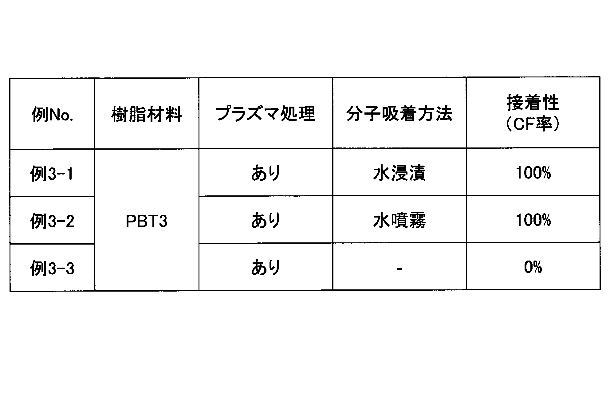
- Examples 3-1 to 3-3 Test pieces were prepared in the same manner as in Example 1-1 to Example 1-3, except that a molded body made of PBT3 was used, and the adhesiveness was evaluated.
- Table 3 shows the results of Examples 3-1 to 3-3.
- Example 4-1 to 4-3 Test pieces were prepared in the same manner as in Example 1-1 to Example 1-3 except that a molded article made of PA (PA6T/6I) was used, and the adhesiveness was evaluated.
- PA PA6T/6I
- Table 4 shows the results of Examples 4-1 to 4-3.
- Test pieces were prepared in the same manner as in Example 1-1 and Example 1-3, except that a molded body made of PEI was used, and the adhesiveness was evaluated.
- Table 5 shows the results of Example 5-1 and Example 5-2.
- Example 6-1 As in Example 2-1, a molded body made of PBT2 was prepared, plasma treated, and cleaned. After that, instead of using water as a treatment liquid, acetone (Sankyo Chemical Co., Ltd., pure acetone, concentration: 99.5% or more) was impregnated into a nonwoven fabric wiper (Bencot) and wiped to apply it to the surface of the molded body. .. The molded body after surface modification was obtained by visually standing until it was visually confirmed that there was no liquid on the surface. A test piece was prepared in the same manner as in Example 2-1, and the adhesiveness was evaluated.
- acetone Sudyo Chemical Co., Ltd., pure acetone, concentration: 99.5% or more
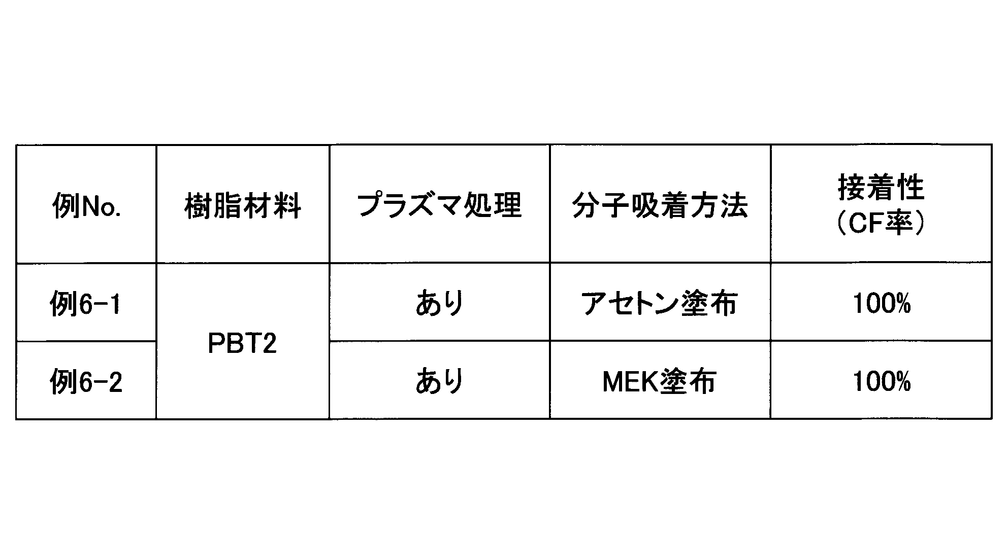
- Example 6-2 Test pieces were prepared in the same manner as in Example 6-1 except that the treatment liquid used was methyl ethyl ketone (MEK) (Gordo Co., Ltd., for business, concentration: 99% or more), and the adhesiveness was evaluated.
- MEK methyl ethyl ketone
- Table 6 shows the results of Example 6-1 and Example 6-2.
- Example 7-1 A molded body of PBT2 was prepared in the same manner as in Example 2-1. Plasma treatment was performed in the same manner as in Example 2-1, except that the irradiation speed was 10 m/min, to perform cleaning. Then, instead of using water as a treatment liquid, ethanol (manufactured by Ganka Chemical Industry Co., Ltd., special grade reagent) was impregnated into a nonwoven fabric wiper (Bencot) and wiped to apply it to the surface of the molded body. The molded body after surface modification was obtained by visually observing until the surface of the molded body was visually confirmed to be free of liquid. A test piece was prepared in the same manner as in Example 2-1 except that the curing time was 4 days, and the adhesiveness was evaluated.
- ethanol manufactured by Ganka Chemical Industry Co., Ltd., special grade reagent
- Example 7-2 A test piece was prepared in the same manner as in Example 7-1 except that butyl acetate (manufactured by WAKO, special reagent grade) was used as the treatment liquid, and the adhesiveness was evaluated.
- butyl acetate manufactured by WAKO, special reagent grade
- Table 7 shows the results of Example 7-1 and Example 7-2.
- Example 8-1 a plate-shaped molded product (25 mm ⁇ 150 mm ⁇ 5 mm) made of the resin PBT1 was prepared, and plasma treatment was performed under the same conditions as in Example 1-1 for cleaning. Subsequently, in this example, the molded body after the plasma treatment was placed in a space under an environment of room temperature (23° C.) and a humidity of 50% RH and stored for 24 hours to prepare a test piece. Adhesion was evaluated in the same manner as in Example 1-1.
- Example 8-2 A test piece was prepared in the same manner as in Example 8-1 except that the test piece was stored in a space under an environment of a humidity of 80% RH for 1 hour, and the adhesiveness was evaluated.
- Example 8-3 A test piece was prepared in the same manner as in Example 8-1 except that it was stored in a space under an environment of a humidity of 80% RH for 24 hours, and the adhesiveness was evaluated.
- Example 8-4 A test piece was prepared in the same manner as in Example 8-1 except that the test piece was stored in a space under an environment of a humidity of 90% RH for 1 hour, and the adhesiveness was evaluated.
- Example 8-5 A test piece was obtained in the same manner as in Example 8-1 except that it was stored in a space under the environment of a humidity of 90% RH for 24 hours, and the adhesiveness was evaluated.
- Example 9-1 to 9-5 Test pieces were prepared in the same manner as in Example 8-1 to Example 8-5 except that a molded body made of PBT2 was used, and the adhesiveness was evaluated.
- Example 10-1 to Example 10-5 Test pieces were prepared in the same manner as in Example 8-1 to Example 8-5 except that a molded body made of PBT3 was used, and the adhesiveness was evaluated.
- Example 10-1 to 10-5 are shown in Table 10 (Example 3-3 is reprinted).
- Vehicle structure 10 Glass (transparent substrate) 15 Shielding Layer 20 Resin Bracket (Resin Molded Body) 30 adhesive layer
Landscapes
- Chemical & Material Sciences (AREA)
- Health & Medical Sciences (AREA)
- Chemical Kinetics & Catalysis (AREA)
- Medicinal Chemistry (AREA)
- Polymers & Plastics (AREA)
- Organic Chemistry (AREA)
- Engineering & Computer Science (AREA)
- Manufacturing & Machinery (AREA)
- Materials Engineering (AREA)
- Mechanical Engineering (AREA)
- Treatments Of Macromolecular Shaped Articles (AREA)
- Manufacture Of Macromolecular Shaped Articles (AREA)
Abstract
樹脂表面を有する成形体にプラズマ処理を施すプラズマ処理ステップと、前記プラズマ処理ステップ後の前記成形体の表面に、水及び親水性有機溶剤の少なくとも一方を含む処理液の分子を吸着させる分子吸着ステップと、前記分子吸着ステップ後の前記成形体を、接着剤によって車両用透明基板に接着して車両用構造体を得る接着ステップとを含む。
Description
本発明は、車両用構造体の製造方法、及び車両用成形体の処理方法に関する。
自動車等の車両において用いられる部品として、樹脂製の部品、或いは少なくとも表面に樹脂を有する部品が多く知られている。そのような部品の中には、ガラス等の透明基板に接着剤によって接着されるものもあり、例としては、フロントガラスの内面に車載機器等を取り付けるための樹脂製ブラケット等の成形体が挙げられる。このような成形体は、透明基板に接着剤を介して接着される場合が多い。
ところで、一般に、上記成形体の樹脂表面の接着性を向上させるために、成形体に対してプラズマ照射等を行って成形体の表面を改質することが知られている(例えば、特許文献1)。
しかしながら、上述のような樹脂表面を有する成形体と車両用透明基板とを接着剤を介して接着する場合において、成形体の樹脂表面をプラズマ等によって処理しただけでは、成形体と接着剤との間の接着性が十分でないことがある。そのため、成形体と車両用透明基板とを接着剤によって接着させてなる構造体を製造する上で、成形体と接着剤との接着性を向上させる方法が求められている。
上記の点に鑑みて、本発明の一態様においては、透明基板と樹脂表面を有する成形体とを接着剤によって接着させてなる構造体の製造において、樹脂表面を有する成形体と接着剤との接着性を向上させることができる製造方法を提供することを課題とする。
上記課題を解決するために、本発明の一態様は、樹脂表面を有する成形体にプラズマ処理を施すプラズマ処理ステップと、前記プラズマ処理ステップ後の前記成形体の表面に、水及び親水性有機溶剤の少なくとも一方を含む処理液の分子を吸着させる分子吸着ステップと、前記吸着ステップ後の前記成形体を、接着剤によって車両用透明基板に接着して車両用構造体を得る接着ステップとを含む、車両用構造体の製造方法である。
本発明の一態様によれば、透明基板と樹脂表面を有する成形体とを接着剤によって接着させてなる構造体の製造において、樹脂表面を有する成形体と接着剤との接着性を向上させることができる製造方法を提供することができる。
以下、本発明を実施するための形態について説明するが、本発明は、下記の形態に限定されることはない。
<プラズマ処理ステップ>
プラズマ処理ステップは、樹脂表面を有する成形体の表面にプラズマを照射するステップである。本ステップにおいて用いられるプラズマ発生手段は、特に限定されず、高周波プラズマ発生装置、又は低周波プラズマ発生装置であってもよい。また、プラズマ処理ステップにおけるプラズマ処理は、コロナを発生し得る、いわゆるコロナ処理と呼ばれる処理であってよい。さらに、レーザーやマイクロ波等の照射によって発生したプラズマを利用する処理であってもよい。
プラズマ処理ステップは、樹脂表面を有する成形体の表面にプラズマを照射するステップである。本ステップにおいて用いられるプラズマ発生手段は、特に限定されず、高周波プラズマ発生装置、又は低周波プラズマ発生装置であってもよい。また、プラズマ処理ステップにおけるプラズマ処理は、コロナを発生し得る、いわゆるコロナ処理と呼ばれる処理であってよい。さらに、レーザーやマイクロ波等の照射によって発生したプラズマを利用する処理であってもよい。
本形態で処理される樹脂表面を有する成形体は、少なくとも表面に樹脂を含むものであればよい。すなわち、樹脂表面を有する成形体は、例えば、成形体全体が主として樹脂から形成されている樹脂製の成形体であってもよいし、樹脂以外の材料からなる成形体の表面の一部又は全部が樹脂で被覆されたものであってもよい。なお、本明細書においては、樹脂表面を有する成形体を、「樹脂成形体」又は単に「成形体」と呼ぶ場合がある。
樹脂表面を有する成形体に用いられる樹脂材料は特に限定されないが、ポリエチレンテレフタレート(PET)、ポリブチレンテレフタレート(PBT)等のポリエステル、ポリエチレン(PE)、ポリプロピレン(PP)等のポリオレフィン、ポリカーボネート(PC)、ナイロン6、ナイロン6,6等のポリアミド(PA)、テレフタル酸やイソフタル酸をベースとした高耐熱ポリアミド(PA6T、PA6I、PA6T/6I等)、ポリイミド(PI)、ポリエーテルイミド(PEI)、アクリロニトリル-ブタジエン-スチレン(ABS)、ポリアセタール(POM)、ポリ塩化ビニル(PVC)、エポキシ(EP)等が挙げられる。これらの樹脂材料は、ホモポリマーとして用いてもよいし、上記の1以上を組み合わせてコポリマーとして用いてもよい。また、樹脂材料は、特に成形体が樹脂製の成形体である場合には、上記の1以上を組み合わせたポリマーアロイ、例えばポリブチレンテレフタレートとスチレンアクリロニトリルとのポリマーアロイ等であると好ましい。
樹脂材料は、繊維、無機粒子等の充填材により強化されている樹脂であってもよい。強化用の繊維としては、ガラス繊維、炭素繊維等が好ましい。繊維強化樹脂としては、ガラス繊維で強化されたポリブチレンテレフタレート、ポリエーテルイミド等が好ましい。樹脂が強化用繊維を含有する場合、繊維は、樹脂全体に対して5~70質量%、好ましくは30~50質量%程度で含有させることができる。
樹脂表面を有する成形体が樹脂製の成形体である場合、その成形方法は限定されず、上述の樹脂材料を射出成形、注型、押出し、ブロー成形等の方法によって成形したものであってよい。また、樹脂以外の材料(金属等)からなるインサート材を用いてインサート成形したものであってもよい。
また、樹脂表面を有する成形体は、樹脂以外の材料からなる成形体の表面の一部又は全部が樹脂で被覆されたものである場合には、例えば、金属等からなる基体に、樹脂を含む電着塗料を用いて電着塗装された電着塗装体であってよい。電着塗装体は、基体(素地)に電解槽中で通電し、樹脂の塗料粒子を部品表面に析出させ、硬化炉で加熱硬化させて膜化したものである。電着塗装によって樹脂表面を形成する場合、電着塗料はカチオン電着塗料であると好ましい。また、電着塗料に含まれる樹脂は、エポキシ樹脂等の熱硬化型樹とすることができ、アミンやアンモニウム等で変性されたエポキシ樹脂を含むことが好ましい。一方、上記基体は、鋼、アルミニウム等を含む金属の成形体、特に板状成形体とすることができる。電着塗装体の例としては、青木電器工業製のカチオン電着塗装鋼板(電着塗料として関西ペイント社製エレクロンHG-305E黒を使用)等が挙げられる。
また、樹脂表面は、基体の上に、樹脂を含む溶液若しくは分散液、又は樹脂の溶融液等を塗布すること、或いは予め形成しておいたシート状の樹脂層を被着することや、無電解めっき等によっても形成することができる。
なお、樹脂表面を有する成形体は、基体表面の少なくとも一部が樹脂層で覆われていればよい。また、樹脂表面を有する成形体においては、後述の車両用透明基板と接着される面(接着面)の少なくとも一部が樹脂層で覆われていればよく、接着面全体が樹脂層で覆われていることが好ましい。
本発明の一実施形態では、上述のような樹脂表面を有する成形体を、まずプラズマ処理ステップによって化学的に表面改質することができる。プラズマ処理ステップによって、樹脂表面に、水酸基、カルボニル基、カルボキシル基といった親水性官能基を導入又は形成することができ、単位面積あたりの親水性官能基の数を増加させることができる。これにより、樹脂表面を有する成形体を、樹脂表面を接着面として、ウレタン系接着剤等の接着剤を塗布して透明基板等の被着体と接着させる場合には、表面の親水性官能基と接着剤の成分とが化学結合又は分子間力により相互作用できる箇所を増やすことができ、成形体と接着剤との間の結合(界面結合)を強固にすることができる。
その一方で、単位面積あたりの親水性官能基の数が増えることは、親水性分子が吸着できるサイトを増加させることができ、成形体の樹脂表面に安定的に存在できる親水性分子の量(密度)を増やすことができることを意味する。本発明の一形態によれば、接着剤を塗布する前にそのようなサイトに対してあらかじめ分子吸着を行っておくことにより成形体と接着剤との界面での接着剤の硬化促進という後述の効果を高められることを見出した。
プラズマ照射の条件は、成形体に用いられている樹脂及び接着剤の種類、成形体の使用目的及び車両での使用場所に応じて、適宜調整することができる。プラズマ発生装置や成型体の構成材料等によるため一概にはいえないが、例えば、プラズマ発生手段の電源の印加電圧の周波数は50Hz~2.45GHz、好ましくは50Hz~25kHzであり、照射距離(電極と成形体表面との距離)は50mm以下、好ましくは10mm~30mmである。対向させるノズルとワーク(成形体)との距離の下限は特に限定されないが、例えば0.5mm以上である。出力電力密度は15W/cm2以上であり、好ましくは20W/cm2である。照射時間はノズルの移動速度によって定められる。ノズルの移動速度は、0.01m/分~50m/分とすることができ、好ましくは2.5m/分~10m/分であり、より好ましくは2.5m/分~4m/分である。照射距離が10mmであり、かつノズルの移動速度が2.5m/分~4m/分の範囲であれば、改質しづらいプラスチックでも改質できる。
プラズマ処理ステップを行う場合、プラズマ照射の前に予め成形体をヒータ等で加熱する等して、樹脂表面を有する成形体の表面温度を高めておくと、後続のステップを経て得られる構造体における成形体と接着剤との間の接着性をさらに向上させることができる。また、得られる車両用構造体の熱水耐久性(成形体と透明基板とを接着剤により接着した後、熱水中に所定時間浸漬させた場合の耐久性)も向上させることができる。
プラズマ照射前の成形体の表面温度は、例えば常温(15℃~25℃)を超える温度に上げておくことができ、例えば、60℃以上、好ましくは80℃以上、より好ましくは100℃以上、さらに好ましくは120℃以上、さらに好ましくは140℃以上とすることができる。
なお、プラズマ処理ステップでは、照射するプラズマの強さや時間等の条件によって、上述の化学的な改質に加え、成形体の樹脂表面に微細な凹凸を形成する等の、物理的な表面改質も可能である。
なお、プラズマ処理ステップを行う前の成形体の保管温度に関して、吸湿性の高い材質、例えば飽和吸水率が1%以上であるポリアミドなど、を保管する場合は、保管温度は25℃以下であることが望ましい。
<分子吸着ステップ>
分子吸着ステップでは、上記プラズマ処理ステップ後の成形体の表面に処理液を供給することによって、成形体の樹脂表面に処理液の分子を吸着させることができる。処理液は、水及び親水性有機溶剤の少なくとも一方を含んでいてよい。すなわち、処理液は、水、若しくは親水性有機溶剤を1種以上含むもの、又は水と親水性有機溶剤の1種以上とを混合した混合物とすることができる。
分子吸着ステップでは、上記プラズマ処理ステップ後の成形体の表面に処理液を供給することによって、成形体の樹脂表面に処理液の分子を吸着させることができる。処理液は、水及び親水性有機溶剤の少なくとも一方を含んでいてよい。すなわち、処理液は、水、若しくは親水性有機溶剤を1種以上含むもの、又は水と親水性有機溶剤の1種以上とを混合した混合物とすることができる。
本明細書において、「成形体の表面に分子を吸着させる」とは、成形体の樹脂表面に存在する官能基に分子を分子間力によって結合させることを指し、成形体の樹脂表面に分子を、いわゆる単層吸着させることを指すと言ってもよい。また、「表面吸着分子」又は「吸着分子」とは、成形体の樹脂表面に存在する官能基に直接結合された分子を指す。これに対し、成形体の樹脂表面に存在している分子であっても、成形体の樹脂表面に存在する官能基に直接結合されていない分子を、「凝縮分子」と呼ぶ場合がある。
上述のように、プラズマ処理ステップによって成形体の樹脂表面には親水性官能基が導入又は形成されるが、このような親水性官能基には、水分子や親水性分子が結合しやすくなっている。そのため、水及び親水性有機溶剤の少なくとも一方を含む処理液を成形体表面に供給することによって、水又は親水性有機溶剤の分子を、成形体の樹脂表面に容易に吸着させることができる。すなわち、成形体の樹脂表面に存在する親水性官能基に、水分子及び/又は親水性有機溶剤の分子を、水素結合、ファンデルワールス力等によって直接的に結合させることができる。このような直接的な結合によって、処理液分子を安定的に成形体の樹脂表面に存在させることができる。
本形態による製造方法では、分子吸着ステップの後にさらに、接着剤を用いて透明基板等の被着体を接着させる工程を含む(後述の接着ステップ)。鋭意研究を重ねた結果、上述のように成形体表面に吸着した処理液分子がある方が、成形体と接着剤との接着性を確実に向上させられることが明らかになった。ひいては成形体と透明基板等の被着体との接着強度を向上させることができる。この詳細なメカニズムについてはまだ明らかになっていないが、吸着分子が分子間力を高める作用、若しくは、界面近傍の硬化を促進する作用を持っていることが推定される。
前者の作用は、吸着分子が存在していることにより接着剤と樹脂表面との濡れ性が向上し、静電相互作用やファンデルワールス力等の分子間力が働きやすくなると説明され得る。
また、後者の作用については、次のように考えられる。一般に接着剤には、接着性の成分の他に可塑剤等の添加剤が含まれているが、接着剤の硬化が遅いとそのような添加剤成分は界面に移行して、成形体と被着体との接着力を低下させる場合がある。これに対して、成形体の樹脂表面に存在する処理液分子によって接着剤の硬化が促進されることで、添加剤成分の界面付近への移行を阻止することができ、接着剤中の添加剤成分が、成形体と接着剤との界面での接着性に及ぼす影響を低減することができると考えられる。
上述のように、処理液は水及び親水性有機溶剤の少なくとも一方を含む。ここで、処理液中の水と親水性有機溶剤との合計量は、80質量%以上であると好ましく、90質量%以上であるとより好ましく、95質量%以上であるとさらに好ましい。また、処理液は、水若しくは親水性有機溶剤、又はその混合物であると好ましい。
処理液は、低コストで安全性及び操作性が高いことから水を含んでいると好ましい。実施例では処理液として蒸留水を用いていることからわかるように、特別な添加物を必要としない。処理液中の水の量は、処理液100質量%に対して、60質量%以上である好ましく、80質量%以上であるとより好ましく、90質量%以上であるとさらに好ましく、処理液が水であるとさらに好ましい。
処理液が親水性有機溶剤を含む場合、含まれる親水性有機溶剤は、成形体の樹脂表面に存在する親水性基と親和性があり且つ成形体に用いられている樹脂材料を変性させない有機溶剤であれば、特に限定されない。
処理液に用いられる親水性有機溶剤としては、メタノール、エタノール、2-プロパノール(イソプロピルアルコール)、1-プロパノール等のアルコール;アセトン、メチルエチルケトン、メチルイソブチルケトン等のケトン;酢酸ブチル、酢酸エチル、グリコールエステル等のエステル;n-ヘキサン、シクロヘキサン等の脂肪族又は脂環式炭化水素;ジエチルエーテル、グリコールエーテル等のエーテル等が挙げられる。これらの有機溶剤は、単独で又は2種以上を組み合わせて用いることができる。また、これらの有機溶剤のうち、メタノール、エタノール、アセトン、メチルエチルケトン、酢酸ブチル、酢酸エチルのうち1種以上を用いることが好ましい。
なお、有機溶剤には不可避的に微量の水を含むものがある。この不可避的に含まれる水は、有機溶剤の製造段階で除去不能であったり、或いは処理液の調製段階で積極的に添加していないにもかかわらず混入したりする水である。例えば、一般的に、有機溶剤は、有機溶剤100質量%に対して、5質量%以下、1質量%以下、0.5質量%以下、0.2質量%以下、0.1質量%以下で、不可避的に水を含み得る。本発明ではそのような微量の水が入っていて純度の下がっている有機溶剤であっても有効である。
そして、このような不可避的に含まれる水分子も、成形体表面の官能基に直接結合できる可能性がある。そのため、後述の接着ステップで、特に湿気硬化型の接着剤を用いた場合には、有機溶剤に不可避的に含まれる水分子によっても、接着剤の硬化が促進され、接着剤との接着性が向上し得る。
よって、処理液が有機溶剤を含む又は処理液が有機溶剤からなる場合、処理液調製前に有機溶剤に含有されている不可避的な水の含有量は、処理液100質量%に対して処理液100質量%に対する水の含有量は、0.001質量%以上、0.1質量%以上、0.2質量%以上、0.4質量%以上、0.5質量%以上、1質量%以上、5質量%以上とすることができる。
処理液が親水性有機溶剤とともに水を含む場合、親水性有機溶剤が揮発性であると、処理液を樹脂成形体表面に供給した後、有機溶剤が先行して揮発し、水分子が成形体の樹脂表面に吸着しやすくなる。すなわち、水分子が、成形体の樹脂表面に存在する官能基と結合しやすくなる。このように吸着分子が主として水分子であると、特に接着ステップで湿気硬化型の接着剤を用いた場合には、接着剤の硬化が促進され、接着剤中の可塑剤等の添加剤成分の移行の阻止等を可能にすることができる。
処理液は、任意の添加剤を含んでいてもよい。処理液に含まれ得る添加剤としては、イソシアネート、シランカップリング剤、防腐剤等が挙げられる。
処理液は、スルホ基を有する有機化合物を実質的に含まないものとすることができる。本明細書において、所定成分を実施的に含まない、とは、処理液を準備する際に構成成分として所定成分を添加しないことを指す。本形態で用いられる処理液中の、スルホ基を有する有機化合物の含有量は、例えば、0.5質量%未満、限定的には0.1質量%以下、より限定的には0.01質量%以下、さらに限定的には0.001質量%未満となり得る。
また、処理液は、スルホ基を有する有機化合物を含めた強酸成分を実質的に含まないものとすることができ、また酸成分を実質的に含まないものとすることができる。酸成分としては、スルホ基を有する有機化合物の他、例えば、塩酸、フッ化水素酸、臭化水素酸、ヨウ化水素酸、硝酸、硫酸等の無機酸、及びカルボン酸、チオール等の有機酸(アルコールを除く)、並びにこれらの誘導体が挙げられる。
処理液がスルホ基を有する有機化合物を実質的に含まないことによって、さらには強酸成分を実質的に含まないものとすることによって、周辺金属が腐食することを低減させられる。特に、処理される成形体がその内部に金属を含む場合には、成形体に含まれる金属の腐食を良好に防止できる。また、自動車等の車両には金属を含む部品が多く用いられているため、車両用構造体の製造において酸成分の使用を実質的に排除することで、車両内の金属部品への悪影響を低減することができる。さらに、処理液が酸成分を実質的に含まないことによって、より安価なプロセスを実現できる。
本形態による製造方法によれば、成形体の樹脂表面に、プラズマ処理ステップにより官能基を導入又は形成させることができるとともに、分子吸着ステップにより処理液分子を吸着させることができる。これにより、その後に塗布される接着剤と成形体表面との結合をより強固にできるともに、成形体との界面及びその付近で接着剤の硬化を促進させ、添加剤成分の移行による接着性の低下を防止することができる。このように、本形態のプラズマ処理及び分子吸着という2つのステップによって、樹脂表面を有する成形体と接着剤との接着性を向上させることができる。よって、本形態によれば、成形体の樹脂表面にプライマー等を塗布しなくとも、接着剤を直接介して成形体と被着体とが高い接着性で接着された構造体を得ることができる。また、接着にプライマーを用いる場合には、成形体とプライマーとの接着性を高めることもできる。
なお、成形体の表面には未処理の状態であっても、接着剤を塗布した場合に接着剤に作用し得る吸着分子(特に、水分子)がある程度存在し得る。しかし、一般的にその量は少なく、本発明の形態によって得られる優れた接着性を得ることは難しい。さらに、成形体の樹脂表面に対してプラズマ処理を行った場合、その処理条件によっては吸着分子が消失してしまう場合がある。例えば、長時間、高出力での照射等の強い条件でプラズマ処理を行うと、吸着分子が散逸してしまう場合がある。そのような場合であっても、本形態ではプラズマ処理を施した後に成形体の樹脂表面に処理液の分子を吸着させるので、プラズマ処理の条件に関わらず、成形体と接着剤との接着性の向上を図ることができる。
分子吸着ステップにおける成形体表面への処理液の供給は、より具体的には、以下のようにして行うことができる。
分子吸着ステップの第1の形態としては、処理液を、用具等を用いて成形体に接触させることが挙げられる。この処理液の接触には、処理液に成形体を接触させた状態で静置することが含まれるし、処理液を成形体に接触させながら成形体に対して相対的に移動させることも含まれる。例えば、成形体を、容器等に入れた処理液に浸漬することができる。ここで、浸漬には、成形体を処理液中に所定時間浸した後に引き上げることに加え、成形体の表面に処理液を掛け流すこと、成形体を処理液で濯ぐことも含まれる。成形体を処理液に浸漬させる場合、バッチ処理、すなわち複数の成形体を同時に浸漬処理することが出来るだけではなく、異なる成形体毎に容器等の浸漬処理構成の変更(ジョブチェンジ)をする必要がなく、自動化がしやすい。
また、処理液の供給は、成形体表面に処理液を散布することによっても可能である。この処理液の散布には、処理液の滴を跳ね掛けること、スプレー等で噴霧すること、加熱水蒸気(スチーム)を吹き付けることも含まれる。さらに、処理液を塗布することもできる。例えば、処理液を布若しくは綿等に浸して、その布又は綿等で成形体の表面を撫でることで、或いは刷毛等を用いて処理液を塗布することができる。一方で、処理液を布若しくは綿等に浸して、その布又は綿等で成形体の表面を撫でる場合、塗布時に布若しくは綿に含まれている繊維や化合物が接着面に残り、接着を阻害する懸念がある。また静電気が発生し、塗布面に異物が吸着する虞もある。したがって、成形体を容器等に入れた処理液に浸漬させるか、成形体表面に処理液を散布させる方法が好ましい。なお、処理液を塗布により供給するのであれば、成形体の表面に圧力がかからないように、又は成形体表面にかかる圧力を0.2kPa以下程度に抑えて行うことが好ましい。これにより、繊維や化合物が接着面に残る可能性を低減できる。
分子吸着ステップの第2の形態としては、処理液(処理液の分子)が気体状態で存在できる空間を形成し、その空間内で樹脂表面が晒されるようにして成形体を配置することが挙げられる。例えば、処理液を構成する水及び親水性有機溶剤の少なくとも一方の蒸気圧が高められた空間を形成し、その空間内に成形体を所定時間保管する。これにより、成形体の樹脂表面に、気体状態の処理液分子を吸着させることができる。成形体は、少なくとも吸着平衡となるような時間にわたって保管すると好ましい。
処理液が水の場合には、成形体を高湿環境下に保管することができる。ここで、高湿環境とは、常湿(相対湿度45~85%RH)を超える湿度の環境であってよい。また、高湿環境下での保管による分子吸着は、60%RH以上、好ましくは80%RH以上、より好ましくは90%RH以上の相対湿度の環境下での保管とすることができる。なお、60%RH以上の高湿環境下で吸湿性の高い材質、例えば飽和吸水率が1%以上であるポリアミド等を保管する場合は、保管温度は30℃以下であることが望ましい。
分子吸着ステップの第1の形態及び第2の形態のいずれにおいても、ステップ後には、少なくとも、成形体表面の官能基に対して吸着平衡となる量で処理液分子が吸着していることが好ましい。
また、プラズマ処理ステップの前には、成形体の表面を公知の方法で清浄化することができる。すなわち、本形態による製造方法では、プラズマ処理ステップの前に、清浄化ステップを有していてよい。清浄化ステップによって、成形体表面の微細な塵又は汚れを物理的又は化学的に予め除去できる。すなわち、清浄化の具体的な例としては、成形体表面に存在する塵若しくは汚れを機械的な力で取り去ること、塵又は汚れを溶剤等に溶解すること、塵又は埃を溶剤よって分解すること、またその組み合わせが挙げられる。上記のうち、清浄化を効率的に行うことができることから、機械的な力を加えることを含むことが好ましい。
成形体表面の塵又は汚れを予め十分に除去しておくことができれば、後続のプラズマ処理において、より多くの親水性官能基を成形体表面へ導入でき、また親水性官能基が成形体表面と、より安定的な結合を形成できる。そのため、プラズマ処理の条件を過度に高くする必要がなくなり、過剰な表面処理によって樹脂表面が損傷する可能性を低減することができる。
清浄化の方法は特に限定されないが、拭き取り、研磨、洗浄等が挙げられる。拭き取りにおいては、少なくともプラズマ処理を行おうとする範囲で成形体の表面を拭き取り用具で拭う。この際、拭き取り用具の拭き取り用素材に溶剤を染み込ませてもよい。拭き取り用具は、例えば、溶剤を吸収して保持できる、繊維を含む又は多孔質の拭き取り用素材を備えたものであってよい。拭き取り用素材は、布、不織布等のシート状材料、スポンジのような塊状材料であってよい。溶剤は、成形体表面に存在し得る塵又は汚れを分散又は溶解可能なもので、揮発性であると好ましい。
拭き取りにおいては、溶剤によって汚れを分解したり、汚れを溶剤中に溶解したりしながら、成形体表面から塵や汚れを機械的な力で取り去ることができる。拭き取りにおいては、成形体表面に圧力がかからないように行ってもよいし、成形体表面に0.2kPa~60kPa程度の圧力がかかるように行ってもよい。圧力をかけて拭き取りを行うことで、成形体表面の汚れを確実に取り去ることができる。
研磨によって清浄化を行う場合には、研磨剤及び研磨具を用いた公知の表面研磨方法を用いることができる。研磨によって、樹脂成形体の表面の材料がわずかに削り取られるので、樹脂表面の汚れを十分に除去することができる。研磨剤としては、例えば、鉱物粒子又は鉱物粒子の分散液等を用いることができるが、二酸化炭素のような昇華性を有する、すなわち常温常圧で昇華する物質の粒子を用いてもよい。昇華性を有する粒子を使用することで研磨工程の終了後に研磨剤を除去する必要がなくなる。
洗浄は、樹脂成形体の公知の洗浄方法を用いることができる。例えば、成形体を、溶剤等の洗浄液に浸漬させ、所定時間静置した後に引き上げることによって行うことができる。また、成形体を洗浄液に浸漬させた後、洗浄液を流動させる等して成形体の表面に対して相対的に動かしてもよい。また、例えば洗浄液を成形体に掛け流してもよい。溶剤は、成形体表面に存在し得る塵又は汚れを分散又は溶解可能なもので、揮発性であると好ましい。
<過剰分子除去ステップ>
上記分子吸着ステップの後には、処理液の付与方法にもよるが、成形体表面には、処理液分子が過剰に存在していることがある。そのような場合、接着剤の分子と樹脂表面の分子とが相互作用する程度に接近することが難しく接着できないという不具合が生じ得る。よって、成形体の樹脂表面における親水性官能基の量と処理液分子の量とのバランスが重要になる。
上記分子吸着ステップの後には、処理液の付与方法にもよるが、成形体表面には、処理液分子が過剰に存在していることがある。そのような場合、接着剤の分子と樹脂表面の分子とが相互作用する程度に接近することが難しく接着できないという不具合が生じ得る。よって、成形体の樹脂表面における親水性官能基の量と処理液分子の量とのバランスが重要になる。
そこで、本形態による製造方法は、上記分子吸着ステップの後に、過剰の処理液分子を除去する過剰分子除去ステップを有していてもよい。このような過剰分子除去ステップでは、処理液の凝縮分子の少なくとも一部を除去することができる。また、処理液の凝縮分子を除去して、処理液が主として吸着分子として成形体表面に存在している状態にすることができる。このように、過剰分子除去ステップでは、凝縮分子が除去されて、吸着分子が除去されないことが好ましい。そのため、過剰分子除去ステップには、過度に高温な熱、気体の吹付けといった乾燥等による処理液分子の強制的な除去は含まれない。
過剰分子除去ステップの具体的な手法としては、分子吸着ステップ後の成形体を所定時間にわたり放置して処理液を自然蒸発させてもよいし、目に見える処理液を布や綿等に吸収させてもよい。過剰分子除去ステップでは、成形体の樹脂表面に少なくとも、目視で処理液が確認できない状態になるまで処理液を除去することが好ましい。
過剰分子除去ステップによって、過剰な処理分子を除去することができ、成形体表面における処理液分子の存在状態を最適化することができる。すなわち、成形体の表面に存在する親水性官能基の量(密度)と、処理液分子の量(密度)とのバランスをとることができる。これにより、接着剤を塗布した際に、成形体表面と接着剤との間での界面結合と、接着剤内での凝集とのバランスをとることが可能となる。
なお、過剰分子除去ステップのあるなしに関わらず、次に説明する接着ステップの直前では、表面に吸着している単位面積当たりの処理液分子の量が、13~15H2O個/nm2である状態が好ましい。なお、この数値は吸着水分子の理論最大密度である。
<接着ステップ>
分子吸着ステップの後、場合によっては上述の過剰分子除去ステップの後、樹脂表面を有する成形体を、接着剤によって車両用透明基板に接着させることができる。
分子吸着ステップの後、場合によっては上述の過剰分子除去ステップの後、樹脂表面を有する成形体を、接着剤によって車両用透明基板に接着させることができる。
接着ステップでは、成形体の、プラズマ処理が施された後に処理液分子が吸着された樹脂表面に、接着剤塗布して、車両用透明基板を重ねることができる。或いは、車両用透明基板に接着剤を塗布し、接着剤に成形体の樹脂表面を重ねることができる。いずれの場合でも、車両透明基板側には、透明基板専用のプライマーを塗布してもよい。
接着ステップで用いられる接着剤は、一液又は二液の湿気硬化型の接着剤であると好ましく、ウレタン系接着剤、変性シリコーン系接着剤等であるとより好ましい。湿気硬化型の接着剤を用いる場合、水を含む処理液を用いることで接着剤の硬化を促進させることができる。一液又は二液の湿気硬化型の接着剤以外に、光硬化型の接着剤や、熱硬化型の接着剤を用いることもできる。光硬化型の接着剤や、熱硬化型の接着剤を用いる場合、吸着分子によりプラズマ処理ステップ後の樹脂成形体表面と接着剤との濡れ性が向上する作用により接着性が向上していると推測される。
接着ステップは、接着剤で接着した後に、樹脂表面を有する成形体と透明基板とを接着剤を介して接着してなる構造体は、所定の環境で保管する、すなわち養生してもよい。
養生の最適な条件は、成形体及び接着剤の材料、プラズマ処理ステップ及び分子吸着ステップの条件等によって異なるが、養生温度は5~35℃が好ましい。また、養生時の湿度は、20~80%RH程度とすることができる。なお、構造体を加熱する等することにより、高温下で養生、例えば常温を超える温度で養生することもできる。これにより、接着剤と成形体との間の接着性を一層高めることができる。
本形態で用いられる車両用透明基板は、車両用ガラス、例えばフロントガラス、リアガラス、サイドガラス等とすることができる。車両用ガラスは、ソーダライムシリケートガラス、アルミノシリケートガラス、ボレートガラス、リチウムアルミノシリケートガラス、ホウ珪酸ガラス等のガラス板から形成されていてよい。ガラス板は未強化であってよく、風冷強化又は化学強化処理が施されていてもよい。未強化ガラスは、溶融ガラスを板状に成形し、徐冷したものである。強化ガラスは、未強化ガラスの表面に圧縮応力層を形成したものである。強化ガラスが風冷強化ガラスである場合は、均一に加熱したガラス板を軟化点付近の温度から急冷し、ガラス表面とガラス内部との温度差によってガラス表面に圧縮応力を生じさせることで、ガラス表面を強化してもよい。一方、強化ガラスが化学強化ガラスである場合は、イオン交換法等によってガラス表面に圧縮応力を生じさせることでガラス表面を強化してもよい。また、車両用ガラスには、紫外線又は赤外線を吸収するガラス板を用いてもよく、さらに透明であることが好ましいが、透明性を損なわない程度に着色されたガラスであってもよい。車両用ガラスには、有機ガラスが用いられていてもよい。有機ガラスとしては、ポリカーボネート等の透明樹脂が挙げられる。
車両用透明基板が車両用ガラスである場合、用いられるガラス板の曲げ成形としては、重力成形、又はプレス成形等が用いられる。ガラス板の成形法についても特に限定されないが、例えば、フロート法等により成形されたガラスが好ましい。また、車両用ガラスは、上述のガラス板を複数備えた合わせガラスとすることができる。合わせガラスを構成するガラス板の間には、エチレンビニルアセタール、ポリビニルブチラール等の中間膜を設けることができる。
車両用透明基板の形状は矩形状等に限定されるものではなく、車両用透明基板は、種々の形状を有するよう加工されたものであってもよい。また、車両用透明基板は湾曲していてよく、その曲率も特に限定されない。但し、車両用透明基板は、樹脂表面を有する成形体を車両用透明基板の面に接着できる、また、成形体との接着性を向上させるのに十分なプラズマ照射を施すことができるような形状及び曲率を有する。
接着ステップにより、成形体と透明基板とが接着剤によって接着されてなる車両用構造体を得ることができる。車両用構造体の具体例としては、車両用窓ガラス、例えばフロントガラスに、車載機器(車載カメラ、車載センサ等)を取り付けるための樹脂製のブラケットや、樹脂製の仮止めピン等の車両用部材が接着されてなる構成であってよい。また、サイドガラスに対して樹脂製のドアスライダーや、樹脂製のドアホルダー等の車両用部材が接着されてなる構造体等であってよい。このように透明基板に接着されて構造体を形成する車両用成形体は、少なくとも接着される部分が板状になっており、また平坦になっているものが好ましい。
図1に、車両用構造体1として、ガラス10に樹脂製ブラケット20が接着された例の車内側の面から見た平面図を示す。図1における構造体は、フロントガラス10の車内側の面に、車載機器用の樹脂製ブラケット20が接着されてなるものである。ブラケット20は、少なくとも車載カメラを支持できるように構成されている。また、図2に、図1のI-I線断面の部分図を示す。図2に示すように、フロントガラス10とブラケット20との間には、接着剤層30が配置されている。なお、車載機器用の樹脂ブラケット20としては、車載カメラに限定されない。レインセンサや赤外線センサ、ミリ波レーダなど、ガラス10に接着された樹脂製ブラケット20が支持できる装置であれば特に限定されない。
図1及び図2に示すように、ガラス10の車内側の面の周縁には、遮蔽層15が設けられていてよい。ガラス10が合わせガラスである場合、遮蔽層15は車外側に位置するガラス板と車内側に位置するガラス板の両方に設けられていてもよいし、いずれか一方にのみに設けられていてもよい。遮蔽層15は、車両用透明基板を車体に接着保持するウレタンシーラントなどを紫外線による劣化から保護する機能を有している。遮蔽層15は、例えば、黒色顔料を含有する溶融性ガラスフリットを含むセラミックカラーペーストを塗布し、焼成することによって形成される。遮蔽層15の厚みは3μm以上15μm以下であることが好ましい。また、遮蔽層15の幅は特に限定されないが、20mm以上300mm以下であることが好ましい。図示の例では、ブラケット20は、ガラス10の車内側の面に設けられた遮蔽層15上に接着されているが、ブラケット20はガラス10の車内側の面に直接接着されてもよい。車外側から見たときに、ブラケット20が遮蔽層15により隠蔽される位置に接着されることが好ましい。ブラケット20が遮蔽層15により隠蔽される位置に接着されると、ブラケット20や接着剤層30が車外側から視認されにくくなるだけではなく、紫外線により接着剤層30が劣化することを抑制できる。
本形態によって得られる車両用構造体においては、プライマーを用いなくとも、樹脂表面を有する成形体と接着剤との間の接着性が高められている。そのため、車両構造体に外部から力が加えられた場合でも、成形体と接着剤との間の界面での剥離が起きにくくなっている。
以下、実施例に基づき、本発明の実施形態についてさらに詳説する。
<樹脂材料>
実施例で用いた成形体の材料は以下の通りである。
・樹脂PBT1:ガラス繊維強化ポリブチレンテレフタレート(ポリプラスチックス株式会社製、「ジュラネックス(登録商標)733LD」)
・樹脂PBT2:ガラス繊維強化ポリブチレンテレフタレート(BASFジャパン株式会社製、「ULTRADUR(登録商標)B4300G6」)
・樹脂PBT3:ガラス繊維強化ポリブチレンテレフタレート(三菱エンジニアリングプラスチックス株式会社製、「ノバデュラン(登録商標)5010G30J」
・樹脂PA:ガラス繊維強化ポリアミド(PA6T/6I)(エムスケミー・ジャパン株式会社製、「グリボリー(登録商標)HTV-3H1 9025」)
・樹脂PEI:ポリエーテルイミド(SABIC社製、「ウルテム(登録商標)1000」)
実施例で用いた成形体の材料は以下の通りである。
・樹脂PBT1:ガラス繊維強化ポリブチレンテレフタレート(ポリプラスチックス株式会社製、「ジュラネックス(登録商標)733LD」)
・樹脂PBT2:ガラス繊維強化ポリブチレンテレフタレート(BASFジャパン株式会社製、「ULTRADUR(登録商標)B4300G6」)
・樹脂PBT3:ガラス繊維強化ポリブチレンテレフタレート(三菱エンジニアリングプラスチックス株式会社製、「ノバデュラン(登録商標)5010G30J」
・樹脂PA:ガラス繊維強化ポリアミド(PA6T/6I)(エムスケミー・ジャパン株式会社製、「グリボリー(登録商標)HTV-3H1 9025」)
・樹脂PEI:ポリエーテルイミド(SABIC社製、「ウルテム(登録商標)1000」)
<接着性評価(ナイフカット試験)>
試験片における成形体と接着性との間の接着性の評価は、ナイフカットによる手剥離試験により行った。手剥離試験は、試験片の接着剤層と板状成形体との間(接着剤と成形体との界面)にカッターナイフで一定の長さの切込みを入れ、その切れ込みから接着剤層を成形体から剥がすように引っ張ることにより行った。一定の力をかけた後、接着剤層と板状成形体との間にさらにカッターナイフを深く入れて切込みを入れて、接着剤層の引剥がしを繰り返し、接着剤の剥離状態を確認した。
試験片における成形体と接着性との間の接着性の評価は、ナイフカットによる手剥離試験により行った。手剥離試験は、試験片の接着剤層と板状成形体との間(接着剤と成形体との界面)にカッターナイフで一定の長さの切込みを入れ、その切れ込みから接着剤層を成形体から剥がすように引っ張ることにより行った。一定の力をかけた後、接着剤層と板状成形体との間にさらにカッターナイフを深く入れて切込みを入れて、接着剤層の引剥がしを繰り返し、接着剤の剥離状態を確認した。
手剥離試験終了後、成形体表面の破壊の状態を目視によって観察し、接着剤が凝集破壊している面積の割合を、凝集破壊率(CF率、単位%)として記録した。なお、CF率0%とは、接着剤が全く凝集破壊しておらず、界面剥離が起こっている状態であり、CF率100%とは、接着剤が塗布された全面にわたって凝集破壊している状態である。CF率が高い程、接着剤に凝集破壊が生じた割合が大きく、成形体と接着剤との接着性が良好であると評価した。
[1.第1の形態による分子吸着(浸漬等)]
(例1-1)
成形体として、樹脂PBT1からなる板状成形体(25mm×150mm×5mm)を準備した。まず、板状成形体の表面を、ヘキサン(シグマ アルドリッチ ジャパン合同会社製、試薬特級)を、不織布ワイパー(旭化成株式会社製、ベンコット(登録商標))にヘキサンを含ませて板状成形体の表面を拭き取ることで清浄化した。
(例1-1)
成形体として、樹脂PBT1からなる板状成形体(25mm×150mm×5mm)を準備した。まず、板状成形体の表面を、ヘキサン(シグマ アルドリッチ ジャパン合同会社製、試薬特級)を、不織布ワイパー(旭化成株式会社製、ベンコット(登録商標))にヘキサンを含ませて板状成形体の表面を拭き取ることで清浄化した。
プラズマ処理装置として、Openair(登録商標)プラズマ装置(プラズマジェネレーターFG5001及びプラズマジェットノズルRD1004を使用、プラズマトリート株式会社製)を用いて、上記の板状成形体に、照射速度(プラズマジェットノズルの移動速度)2.5m/分、照射距離10mmで、プラズマ処理を行った。なお、上記処理装置における電源の印加電圧の周波数は21kHzであった。プラズマ処理時の室温は23℃であった。
プラズマ処理後、処理液として水(蒸留水)を用い、さらなる表面処理を行った。具体的には、容器に入れた水中に板状成形体全体を浸漬させ、1分間経過後、板状成形体を取出した。目視で、成形体表面に水がないと視認できるまで放置し、表面改質された成形体を得た。
そして、表面改質後の板状成形体の表面に、室温(23℃)で、ウレタン系接着剤(横浜ゴム株式会社製、「WS292A」)を、専用の塗布ガンを用いて塗布して、3mm厚の接着剤層を形成し、試験片を得た。試験片を1日間常温常湿で養生した。養生後の試験片に対して、上述のナイフカット試験による接着性評価を行った。結果を表1に示す。
(例1-2)
例1-1と同様の条件でプラズマ処理を行い、表面処理を行った。しかし、その後の処理液分子吸着の処理を、水に浸漬させるのではなく、成形体の表面に処理液である水(蒸留水)を市販の霧吹きを用いて噴霧することによって行い、表面改質された成形体を得た。例1-1と同様に、試験片を作製し、接着性を評価した。
例1-1と同様の条件でプラズマ処理を行い、表面処理を行った。しかし、その後の処理液分子吸着の処理を、水に浸漬させるのではなく、成形体の表面に処理液である水(蒸留水)を市販の霧吹きを用いて噴霧することによって行い、表面改質された成形体を得た。例1-1と同様に、試験片を作製し、接着性を評価した。
(例1-3)
例1-1と同様の条件でプラズマ処理を行い、表面処理を行った。しかし、その後の処理液分子吸着の処理を行なわずに、表面改質された成形体を得た。例1-1と同様に、試験片を作製し、接着性を評価した。
例1-1と同様の条件でプラズマ処理を行い、表面処理を行った。しかし、その後の処理液分子吸着の処理を行なわずに、表面改質された成形体を得た。例1-1と同様に、試験片を作製し、接着性を評価した。
(例1-4)
プラズマ処理を行わなかったこと以外は例1-1と同様にして試験片を作製し、接着性を評価した。
プラズマ処理を行わなかったこと以外は例1-1と同様にして試験片を作製し、接着性を評価した。
例1-1~例1-4の結果を表1に示す。

(例2-1)
成形体としてPBT2からなるものを使用したこと以外は、それぞれ例1-1~例1-3と同様にして、試験片を作製し、接着性を評価した。
成形体としてPBT2からなるものを使用したこと以外は、それぞれ例1-1~例1-3と同様にして、試験片を作製し、接着性を評価した。
例2-1~例2-3の結果を表2に示す。

(例3-1~例3-3)
成形体としてPBT3からなるものを使用したこと以外は、それぞれ例1-1~例1-3と同様にして、試験片を作製し、接着性を評価した。
成形体としてPBT3からなるものを使用したこと以外は、それぞれ例1-1~例1-3と同様にして、試験片を作製し、接着性を評価した。
例3-1~例3-3の結果を表3に示す。
(例4-1~例4-3)
成形体としてPA(PA6T/6I)からなるものを使用したこと以外は、それぞれ例1-1~例1-3と同様にして、試験片を作製し、接着性を評価した。
成形体としてPA(PA6T/6I)からなるものを使用したこと以外は、それぞれ例1-1~例1-3と同様にして、試験片を作製し、接着性を評価した。
例4-1~例4-3の結果を表4に示す。

(例5-1及び例5-2)
成形体としてPEIからなるものを使用したこと以外は、それぞれ例1-1及び例1-3と同様にして、試験片を作製し、接着性を評価した。
成形体としてPEIからなるものを使用したこと以外は、それぞれ例1-1及び例1-3と同様にして、試験片を作製し、接着性を評価した。
例5-1及び例5-2の結果を表5に示す。
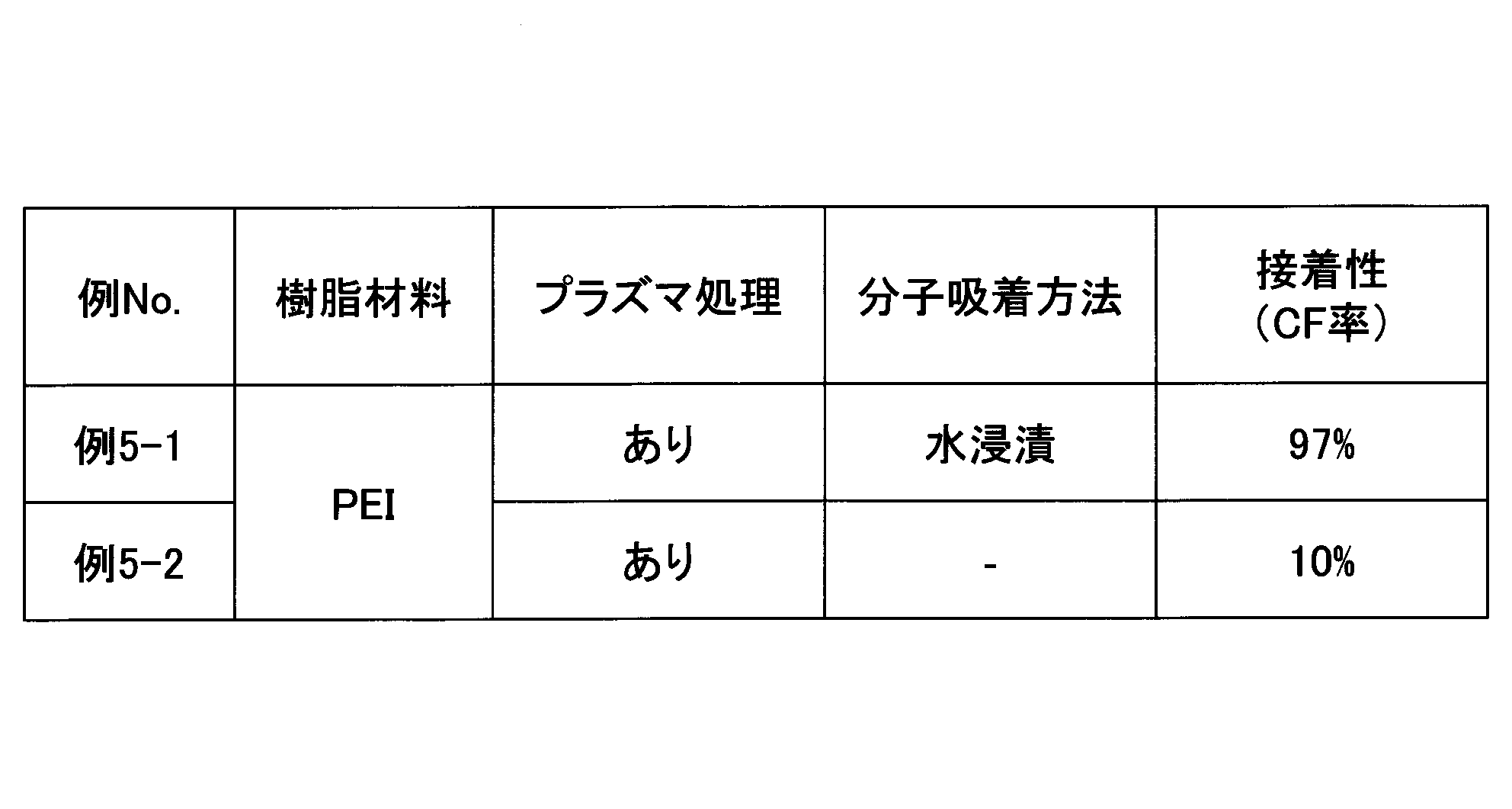
表1~表5より、プラズマ処理を行った後に表面に水分子を吸着させる処理を行うことで、CF率が増大し、接着性が向上することが分かった。なお、表4におけるPA6T/6Iからなる成形体は、プラズマ処理のみでも、他の材料からなる成形体に比べて接着性が高かったが、プラズマ処理を行った後に水分子吸着の処理を行うことで、接着性をさらに向上できることが分かった。
(例6-1)
例2-1と同様に、PBT2からなる成形体を準備し、プラズマ処理を行い、清浄化を行った。その後、処理液として水を用いるのではなく、アセトン(三協化学株式会社、純アセトン、濃度:99.5%以上)を、不織布ワイパー(ベンコット)に染み込ませ拭くことによって成形体表面に塗布した。目視で、成形体表面に液がないと視認できるまで放置して、表面改質後の成形体を得た。例2-1と同様に、試験片を作製し、接着性を評価した。
例2-1と同様に、PBT2からなる成形体を準備し、プラズマ処理を行い、清浄化を行った。その後、処理液として水を用いるのではなく、アセトン(三協化学株式会社、純アセトン、濃度:99.5%以上)を、不織布ワイパー(ベンコット)に染み込ませ拭くことによって成形体表面に塗布した。目視で、成形体表面に液がないと視認できるまで放置して、表面改質後の成形体を得た。例2-1と同様に、試験片を作製し、接着性を評価した。
(例6-2)
用いた処理液を、メチルエチルケトン(MEK)(株式会社ゴードー、業務用、濃度:99%以上)としたこと以外は例6-1と同様にして、試験片を作製し、接着性を評価した。
用いた処理液を、メチルエチルケトン(MEK)(株式会社ゴードー、業務用、濃度:99%以上)としたこと以外は例6-1と同様にして、試験片を作製し、接着性を評価した。
例6-1及び例6-2の結果を表6に示す。
(例7-1)
例2-1と同様に、PBT2からなる成形体を準備した。照射速度を10m/分としたこと以外は例2-1と同様にしてプラズマ処理を行い、清浄化を行った。その後、処理液として水を用いるのではなく、エタノール(甘粕化学産業株式会社製、試薬特級)を不織布ワイパー(ベンコット)に染み込ませ拭くことによって成形体表面に塗布した。目視で、成形体表面に液がないと視認できるまで放置して、表面改質後の成形体を得た。養生時間を4日間としたこと以外は例2-1と同様にして試験片を作製し、接着性を評価した。
例2-1と同様に、PBT2からなる成形体を準備した。照射速度を10m/分としたこと以外は例2-1と同様にしてプラズマ処理を行い、清浄化を行った。その後、処理液として水を用いるのではなく、エタノール(甘粕化学産業株式会社製、試薬特級)を不織布ワイパー(ベンコット)に染み込ませ拭くことによって成形体表面に塗布した。目視で、成形体表面に液がないと視認できるまで放置して、表面改質後の成形体を得た。養生時間を4日間としたこと以外は例2-1と同様にして試験片を作製し、接着性を評価した。
(例7-2)
処理液として酢酸ブチル(WAKO社製、試薬特級)を用いたこと以外は例7-1と同様にして、試験片を作製し、接着性を評価した。
処理液として酢酸ブチル(WAKO社製、試薬特級)を用いたこと以外は例7-1と同様にして、試験片を作製し、接着性を評価した。
例7-1及び例7-2の結果を表7に示す。
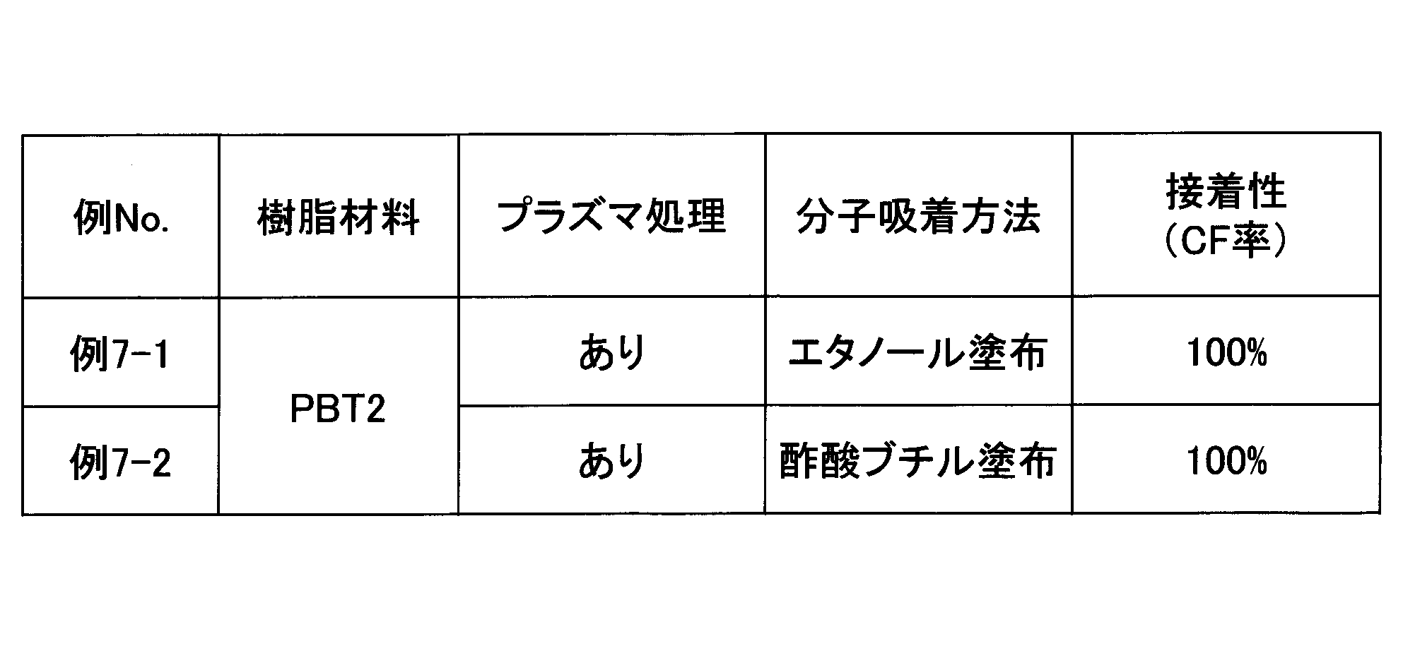
表6及び表7より、プラズマ処理を行った後に所定の有機溶剤を含む処理液の分子を吸着させることで、成形体の良好な接着性が得られることが分かった。
[2.第2の形態による分子吸着(高湿下での保管)]
(例8-1)
例1-1と同様に、樹脂PBT1からなる板状成形体(25mm×150mm×5mm)を準備し、例1-1と同様の条件でプラズマ処理を行い、清浄化を行った。続いて、本例では、プラズマ処理後の成形体を、室温(23℃)、湿度50%RHの環境下の空間内に置いて24時間保管し、試験片を作製した。例1-1と同様にして接着性を評価した。
(例8-1)
例1-1と同様に、樹脂PBT1からなる板状成形体(25mm×150mm×5mm)を準備し、例1-1と同様の条件でプラズマ処理を行い、清浄化を行った。続いて、本例では、プラズマ処理後の成形体を、室温(23℃)、湿度50%RHの環境下の空間内に置いて24時間保管し、試験片を作製した。例1-1と同様にして接着性を評価した。
(例8-2)
湿度80%RHの環境下の空間内に1時間保管したこと以外は例8-1と同様にして、試験片を作製し、接着性を評価した。
湿度80%RHの環境下の空間内に1時間保管したこと以外は例8-1と同様にして、試験片を作製し、接着性を評価した。
(例8-3)
湿度80%RHの環境下の空間内に24時間保管したこと以外は例8-1と同様にして、試験片を作製し、接着性を評価した。
湿度80%RHの環境下の空間内に24時間保管したこと以外は例8-1と同様にして、試験片を作製し、接着性を評価した。
(例8-4)
湿度90%RHの環境下の空間内に1時間保管したこと以外は例8-1と同様にして、試験片を作製し、接着性を評価した。
湿度90%RHの環境下の空間内に1時間保管したこと以外は例8-1と同様にして、試験片を作製し、接着性を評価した。
(例8-5)
湿度90%RHの環境下の空間内に24時間保管したこと以外は例8-1と同様にして、試験片を得て、接着性を評価した。
湿度90%RHの環境下の空間内に24時間保管したこと以外は例8-1と同様にして、試験片を得て、接着性を評価した。
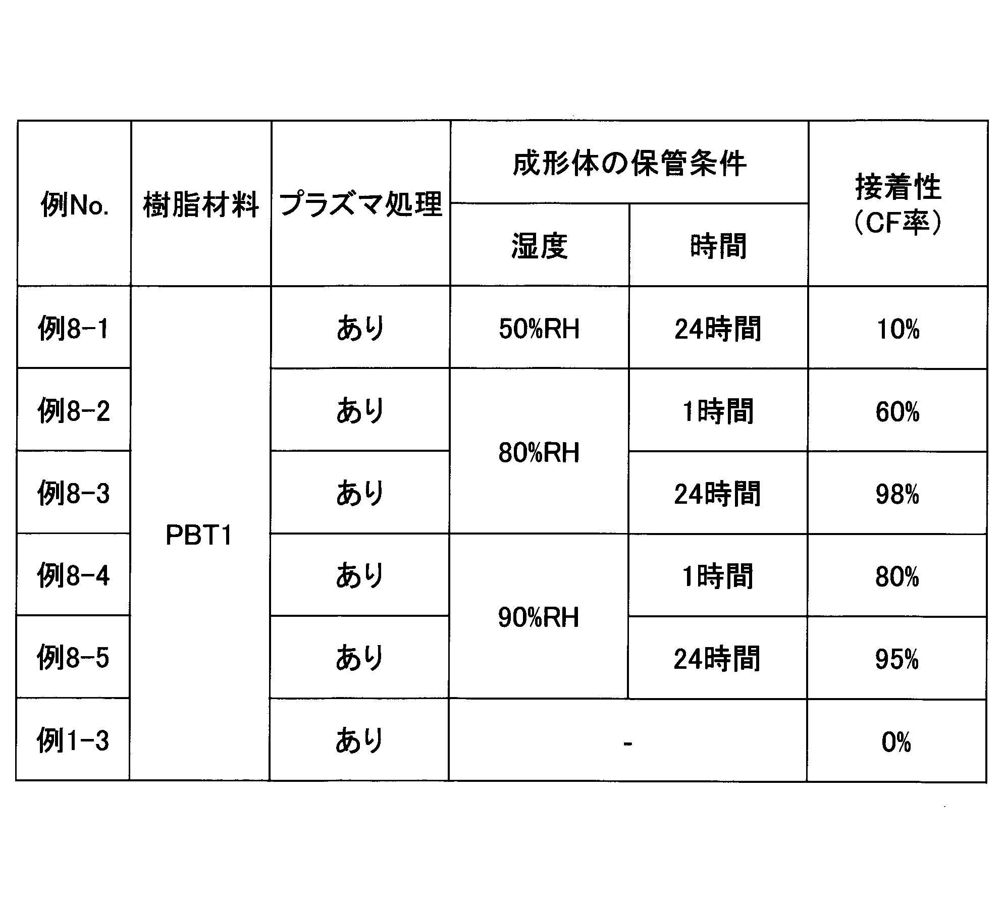
例8-1~例8-5の結果を表8に示す(例1-3は再掲)。
(例9-1~例9-5)
成形体として、PBT2からなるものを使用したこと以外は、それぞれ例8-1~例8-5と同様にして、試験片を作製し、接着性を評価した。
成形体として、PBT2からなるものを使用したこと以外は、それぞれ例8-1~例8-5と同様にして、試験片を作製し、接着性を評価した。
例9-1~例9-5の結果を表9に示す(例2-3は再掲)。

(例10-1~例10-5)
成形体として、PBT3からなるものを使用したこと以外は、それぞれ例8-1~例8-5と同様にして、試験片を作製し、接着性を評価した。
成形体として、PBT3からなるものを使用したこと以外は、それぞれ例8-1~例8-5と同様にして、試験片を作製し、接着性を評価した。
例10-1~例10-5の結果を表10に示す(例3-3は再掲)。

表8~10より、プラズマ処理のみの例(例1-3、例2-3、例3-3)に比べて、プラズマ処理を行った後に処理液分子の吸着の処理を行った例での接着性は向上していることが分かった。特に、80%RH以上の湿度で保管したものについては、接着性の顕著な向上が得られた。
本出願は、2018年12月3日に日本国特許庁に出願された特願2018-226297号に基づく優先権を主張するものであり、その全内容は参照をもってここに援用される。
1 車両用構造体
10 ガラス(透明基板)
15 遮蔽層
20 樹脂製ブラケット(樹脂成形体)
30 接着剤層
10 ガラス(透明基板)
15 遮蔽層
20 樹脂製ブラケット(樹脂成形体)
30 接着剤層
Claims (10)
- 樹脂表面を有する成形体にプラズマ処理を施すプラズマ処理ステップと、
前記プラズマ処理ステップ後の前記成形体の表面に、水及び親水性有機溶剤の少なくとも一方を含む処理液の分子を吸着させる分子吸着ステップと、
前記分子吸着ステップ後の前記成形体を、接着剤によって車両用透明基板に接着して車両用構造体を得る接着ステップとを含む、車両用構造体の製造方法。 - 前記処理液は、スルホ基を有する有機化合物を実質的に含まない、請求項1に記載の製造方法。
- 前記分子吸着ステップは、前記成形体を処理液に浸漬させるか、前記処理液を前記成形体の表面に散布することによって行う、請求項1又は2に記載の製造方法。
- 前記分子吸着ステップは、前記成形体を高湿環境で保管することによって行う、請求項1又は2に記載の製造方法。
- 前記処理液は、水と、アルコール、ケトン、エステル、エーテル、炭化水素の1以上との少なくとも一方を含む、請求項1から4のいずれか一項に記載の製造方法。
- 前記分子吸着ステップ後に、前記処理液の凝縮分子の少なくとも一部を除去する、請求項1から5のいずれか一項に記載の製造方法。
- 前記成形体は、前記樹脂表面がポリエステル、ポリアミド、ポリアセタール、ポリカーボネート、変性ポリフェニレンエーテル、及び、エポキシのうち1以上を含む樹脂からなる、請求項1から6のいずれか一項に記載の製造方法。
- 前記接着剤は、湿気硬化型接着剤である、請求項1から7のいずれか一項に記載の製造方法。
- 前記車両用透明基板は車両用窓ガラスである、請求項1から8のいずれか一項に記載の製造方法。
- 接着剤によって車両用透明基板に接着される樹脂表面を有する車両用成形体の処理方法であって、
樹脂表面を有する成形体にプラズマ処理を施すプラズマ処理ステップと、
前記プラズマ処理ステップ後の前記成形体の表面に、水及び親水性有機溶剤の少なくとも一方を含む処理液の分子を吸着させる分子吸着ステップとを含む、処理方法。
Priority Applications (1)
| Application Number | Priority Date | Filing Date | Title |
|---|---|---|---|
| JP2020559099A JP7600686B2 (ja) | 2018-12-03 | 2019-11-27 | 車両用構造体の製造方法、及び車両用成形体の処理方法 |
Applications Claiming Priority (2)
| Application Number | Priority Date | Filing Date | Title |
|---|---|---|---|
| JP2018-226297 | 2018-12-03 | ||
| JP2018226297 | 2018-12-03 |
Publications (1)
| Publication Number | Publication Date |
|---|---|
| WO2020116273A1 true WO2020116273A1 (ja) | 2020-06-11 |
Family
ID=70974252
Family Applications (1)
| Application Number | Title | Priority Date | Filing Date |
|---|---|---|---|
| PCT/JP2019/046340 Ceased WO2020116273A1 (ja) | 2018-12-03 | 2019-11-27 | 車両用構造体の製造方法、及び車両用成形体の処理方法 |
Country Status (2)
| Country | Link |
|---|---|
| JP (1) | JP7600686B2 (ja) |
| WO (1) | WO2020116273A1 (ja) |
Citations (11)
| Publication number | Priority date | Publication date | Assignee | Title |
|---|---|---|---|---|
| JPS59215328A (ja) * | 1983-05-24 | 1984-12-05 | Stanley Electric Co Ltd | 高分子固体材料表面の親水化方法 |
| JPS62110973A (ja) * | 1985-11-06 | 1987-05-22 | 平岡織染株式会社 | 低温プラズマ処理された基材の処理効果保持方法 |
| JPS6386733A (ja) * | 1986-09-30 | 1988-04-18 | Sumitomo Bakelite Co Ltd | プラズマ処理品の保管方法 |
| JPH0539374A (ja) * | 1991-08-06 | 1993-02-19 | Dainippon Printing Co Ltd | プラスチツクフイルムの表面濡れ性改良方法 |
| JPH07330930A (ja) * | 1994-06-03 | 1995-12-19 | Kanegafuchi Chem Ind Co Ltd | 高分子フィルムの表面処理方法 |
| JPH08502767A (ja) * | 1992-08-26 | 1996-03-26 | シー・アール・バード・インコーポレーテツド | ポリエチレンテレフタレート製品の表面処理方法 |
| JP2001334824A (ja) * | 2000-03-24 | 2001-12-04 | Hori Glass Kk | 自動車用窓ガラスおよびその製造方法 |
| JP2006282871A (ja) * | 2005-03-31 | 2006-10-19 | Univ Nagoya | 疎水性高分子基板表面の親水性維持方法 |
| JP2007190511A (ja) * | 2006-01-20 | 2007-08-02 | Toppan Printing Co Ltd | 基板の表面状態保持方法及び基板 |
| JP2008127428A (ja) * | 2006-11-17 | 2008-06-05 | Yokohama Rubber Co Ltd:The | 樹脂ホルダー用表面処理剤、表面処理された樹脂ホルダー、表面処理された樹脂ホルダーの製造方法および自動車窓ガラスと樹脂ホルダーとの複合体 |
| JP2013220688A (ja) * | 2012-04-13 | 2013-10-28 | Toyota Motor Corp | 補給用樹脂ドア部材及び補給用樹脂ドア部材へのドアガラス取付方法 |
-
2019
- 2019-11-27 JP JP2020559099A patent/JP7600686B2/ja active Active
- 2019-11-27 WO PCT/JP2019/046340 patent/WO2020116273A1/ja not_active Ceased
Patent Citations (11)
| Publication number | Priority date | Publication date | Assignee | Title |
|---|---|---|---|---|
| JPS59215328A (ja) * | 1983-05-24 | 1984-12-05 | Stanley Electric Co Ltd | 高分子固体材料表面の親水化方法 |
| JPS62110973A (ja) * | 1985-11-06 | 1987-05-22 | 平岡織染株式会社 | 低温プラズマ処理された基材の処理効果保持方法 |
| JPS6386733A (ja) * | 1986-09-30 | 1988-04-18 | Sumitomo Bakelite Co Ltd | プラズマ処理品の保管方法 |
| JPH0539374A (ja) * | 1991-08-06 | 1993-02-19 | Dainippon Printing Co Ltd | プラスチツクフイルムの表面濡れ性改良方法 |
| JPH08502767A (ja) * | 1992-08-26 | 1996-03-26 | シー・アール・バード・インコーポレーテツド | ポリエチレンテレフタレート製品の表面処理方法 |
| JPH07330930A (ja) * | 1994-06-03 | 1995-12-19 | Kanegafuchi Chem Ind Co Ltd | 高分子フィルムの表面処理方法 |
| JP2001334824A (ja) * | 2000-03-24 | 2001-12-04 | Hori Glass Kk | 自動車用窓ガラスおよびその製造方法 |
| JP2006282871A (ja) * | 2005-03-31 | 2006-10-19 | Univ Nagoya | 疎水性高分子基板表面の親水性維持方法 |
| JP2007190511A (ja) * | 2006-01-20 | 2007-08-02 | Toppan Printing Co Ltd | 基板の表面状態保持方法及び基板 |
| JP2008127428A (ja) * | 2006-11-17 | 2008-06-05 | Yokohama Rubber Co Ltd:The | 樹脂ホルダー用表面処理剤、表面処理された樹脂ホルダー、表面処理された樹脂ホルダーの製造方法および自動車窓ガラスと樹脂ホルダーとの複合体 |
| JP2013220688A (ja) * | 2012-04-13 | 2013-10-28 | Toyota Motor Corp | 補給用樹脂ドア部材及び補給用樹脂ドア部材へのドアガラス取付方法 |
Also Published As
| Publication number | Publication date |
|---|---|
| JP7600686B2 (ja) | 2024-12-17 |
| JPWO2020116273A1 (ja) | 2021-10-21 |
Similar Documents
| Publication | Publication Date | Title |
|---|---|---|
| CN111962049B (zh) | 等离子化学气相沉积的纳米超疏水涂层及其制备方法 | |
| JP2019194016A (ja) | 表面改質シート、表面改質部材、塗装物、及び塗装物の製造方法 | |
| JP5563195B2 (ja) | 改質物質を用いる活性化方法 | |
| CN101096293A (zh) | 为进行粘接而处理基板的方法 | |
| EP1732707B1 (en) | Activation method | |
| TW202039662A (zh) | 積層體之製造方法、塗裝物之製造方法、接合構造體之製造方法、熱轉印片材、及積層體 | |
| JP5094387B2 (ja) | ガラス表面の活性化 | |
| JP4812308B2 (ja) | コーティング液およびコーティング方法 | |
| JP7600686B2 (ja) | 車両用構造体の製造方法、及び車両用成形体の処理方法 | |
| EP2160365B1 (en) | Method of preparing glass and ceramic enamels on glass for adhesive bonding | |
| WO2007141921A1 (ja) | コーティング液およびコーティング方法 | |
| DE102013220014A1 (de) | Verfahren, Systeme, Komponenten und Zusammensetzungen zum gleichzeitigen Behandeln eines Substrats und Kleben oder Aufbringen eines Haftmittels an/auf dieses | |
| JP2024090947A (ja) | 被着体付き車両用窓ガラスの製造方法 | |
| JP2025005529A (ja) | 被着体付き車両用窓ガラスの製造方法 | |
| JP7779091B2 (ja) | 自動車用窓ガラス構造体の製造方法、及び乾式処理の評価方法 | |
| US20190322016A1 (en) | Method for bonding injection molded plastics | |
| JP2005113129A (ja) | 環境を破壊しないワイプ溶剤組成及びプロセス | |
| US3802906A (en) | Method of improving wire adhesion to rubber | |
| KR102063914B1 (ko) | 코팅 시스템 | |
| WO2019208666A1 (ja) | 表面改質シート、表面改質部材、塗装物、及び塗装物の製造方法 | |
| JP4269993B2 (ja) | 表面処理方法 | |
| JP2003221458A (ja) | 熱硬化性樹脂成形品の接着方法 | |
| JP6706441B2 (ja) | 合成樹脂材塗装の前処理方法 | |
| JP4317044B2 (ja) | 潜在的水濡れ性付与成形体及び水濡れ性付与成形体 | |
| CN119119950A (zh) | 用于复合材料的粘合促进剂及其方法 |
Legal Events
| Date | Code | Title | Description |
|---|---|---|---|
| 121 | Ep: the epo has been informed by wipo that ep was designated in this application |
Ref document number: 19893294 Country of ref document: EP Kind code of ref document: A1 |
|
| ENP | Entry into the national phase |
Ref document number: 2020559099 Country of ref document: JP Kind code of ref document: A |
|
| NENP | Non-entry into the national phase |
Ref country code: DE |
|
| 122 | Ep: pct application non-entry in european phase |
Ref document number: 19893294 Country of ref document: EP Kind code of ref document: A1 |