WO2020116220A1 - 自動車用ペダルストローク検出装置および自動車用コントロールユニット - Google Patents
自動車用ペダルストローク検出装置および自動車用コントロールユニット Download PDFInfo
- Publication number
- WO2020116220A1 WO2020116220A1 PCT/JP2019/045915 JP2019045915W WO2020116220A1 WO 2020116220 A1 WO2020116220 A1 WO 2020116220A1 JP 2019045915 W JP2019045915 W JP 2019045915W WO 2020116220 A1 WO2020116220 A1 WO 2020116220A1
- Authority
- WO
- WIPO (PCT)
- Prior art keywords
- value
- magnetic flux
- stroke
- detection device
- magnet
- Prior art date
- Legal status (The legal status is an assumption and is not a legal conclusion. Google has not performed a legal analysis and makes no representation as to the accuracy of the status listed.)
- Ceased
Links
Images





Classifications
-
- B—PERFORMING OPERATIONS; TRANSPORTING
- B60—VEHICLES IN GENERAL
- B60T—VEHICLE BRAKE CONTROL SYSTEMS OR PARTS THEREOF; BRAKE CONTROL SYSTEMS OR PARTS THEREOF, IN GENERAL; ARRANGEMENT OF BRAKING ELEMENTS ON VEHICLES IN GENERAL; PORTABLE DEVICES FOR PREVENTING UNWANTED MOVEMENT OF VEHICLES; VEHICLE MODIFICATIONS TO FACILITATE COOLING OF BRAKES
- B60T8/00—Arrangements for adjusting wheel-braking force to meet varying vehicular or ground-surface conditions, e.g. limiting or varying distribution of braking force
- B60T8/32—Arrangements for adjusting wheel-braking force to meet varying vehicular or ground-surface conditions, e.g. limiting or varying distribution of braking force responsive to a speed condition, e.g. acceleration or deceleration
- B60T8/321—Arrangements for adjusting wheel-braking force to meet varying vehicular or ground-surface conditions, e.g. limiting or varying distribution of braking force responsive to a speed condition, e.g. acceleration or deceleration deceleration
- B60T8/3255—Systems in which the braking action is dependent on brake pedal data
- B60T8/326—Hydraulic systems
-
- B—PERFORMING OPERATIONS; TRANSPORTING
- B60—VEHICLES IN GENERAL
- B60T—VEHICLE BRAKE CONTROL SYSTEMS OR PARTS THEREOF; BRAKE CONTROL SYSTEMS OR PARTS THEREOF, IN GENERAL; ARRANGEMENT OF BRAKING ELEMENTS ON VEHICLES IN GENERAL; PORTABLE DEVICES FOR PREVENTING UNWANTED MOVEMENT OF VEHICLES; VEHICLE MODIFICATIONS TO FACILITATE COOLING OF BRAKES
- B60T13/00—Transmitting braking action from initiating means to ultimate brake actuator with power assistance or drive; Brake systems incorporating such transmitting means, e.g. air-pressure brake systems
- B60T13/10—Transmitting braking action from initiating means to ultimate brake actuator with power assistance or drive; Brake systems incorporating such transmitting means, e.g. air-pressure brake systems with fluid assistance, drive, or release
- B60T13/58—Combined or convertible systems
- B60T13/62—Combined or convertible systems both straight and automatic
-
- B—PERFORMING OPERATIONS; TRANSPORTING
- B60—VEHICLES IN GENERAL
- B60T—VEHICLE BRAKE CONTROL SYSTEMS OR PARTS THEREOF; BRAKE CONTROL SYSTEMS OR PARTS THEREOF, IN GENERAL; ARRANGEMENT OF BRAKING ELEMENTS ON VEHICLES IN GENERAL; PORTABLE DEVICES FOR PREVENTING UNWANTED MOVEMENT OF VEHICLES; VEHICLE MODIFICATIONS TO FACILITATE COOLING OF BRAKES
- B60T13/00—Transmitting braking action from initiating means to ultimate brake actuator with power assistance or drive; Brake systems incorporating such transmitting means, e.g. air-pressure brake systems
- B60T13/10—Transmitting braking action from initiating means to ultimate brake actuator with power assistance or drive; Brake systems incorporating such transmitting means, e.g. air-pressure brake systems with fluid assistance, drive, or release
- B60T13/66—Electrical control in fluid-pressure brake systems
- B60T13/68—Electrical control in fluid-pressure brake systems by electrically-controlled valves
- B60T13/686—Electrical control in fluid-pressure brake systems by electrically-controlled valves in hydraulic systems or parts thereof
-
- B—PERFORMING OPERATIONS; TRANSPORTING
- B60—VEHICLES IN GENERAL
- B60T—VEHICLE BRAKE CONTROL SYSTEMS OR PARTS THEREOF; BRAKE CONTROL SYSTEMS OR PARTS THEREOF, IN GENERAL; ARRANGEMENT OF BRAKING ELEMENTS ON VEHICLES IN GENERAL; PORTABLE DEVICES FOR PREVENTING UNWANTED MOVEMENT OF VEHICLES; VEHICLE MODIFICATIONS TO FACILITATE COOLING OF BRAKES
- B60T17/00—Component parts, details, or accessories of power brake systems not covered by groups B60T8/00, B60T13/00 or B60T15/00, or presenting other characteristic features
- B60T17/18—Safety devices; Monitoring
- B60T17/22—Devices for monitoring or checking brake systems; Signal devices
-
- B—PERFORMING OPERATIONS; TRANSPORTING
- B60—VEHICLES IN GENERAL
- B60T—VEHICLE BRAKE CONTROL SYSTEMS OR PARTS THEREOF; BRAKE CONTROL SYSTEMS OR PARTS THEREOF, IN GENERAL; ARRANGEMENT OF BRAKING ELEMENTS ON VEHICLES IN GENERAL; PORTABLE DEVICES FOR PREVENTING UNWANTED MOVEMENT OF VEHICLES; VEHICLE MODIFICATIONS TO FACILITATE COOLING OF BRAKES
- B60T8/00—Arrangements for adjusting wheel-braking force to meet varying vehicular or ground-surface conditions, e.g. limiting or varying distribution of braking force
- B60T8/17—Using electrical or electronic regulation means to control braking
- B60T8/172—Determining control parameters used in the regulation, e.g. by calculations involving measured or detected parameters
-
- G—PHYSICS
- G01—MEASURING; TESTING
- G01D—MEASURING NOT SPECIALLY ADAPTED FOR A SPECIFIC VARIABLE; ARRANGEMENTS FOR MEASURING TWO OR MORE VARIABLES NOT COVERED IN A SINGLE OTHER SUBCLASS; TARIFF METERING APPARATUS; MEASURING OR TESTING NOT OTHERWISE PROVIDED FOR
- G01D5/00—Mechanical means for transferring the output of a sensing member; Means for converting the output of a sensing member to another variable where the form or nature of the sensing member does not constrain the means for converting; Transducers not specially adapted for a specific variable
- G01D5/12—Mechanical means for transferring the output of a sensing member; Means for converting the output of a sensing member to another variable where the form or nature of the sensing member does not constrain the means for converting; Transducers not specially adapted for a specific variable using electric or magnetic means
- G01D5/14—Mechanical means for transferring the output of a sensing member; Means for converting the output of a sensing member to another variable where the form or nature of the sensing member does not constrain the means for converting; Transducers not specially adapted for a specific variable using electric or magnetic means influencing the magnitude of a current or voltage
- G01D5/142—Mechanical means for transferring the output of a sensing member; Means for converting the output of a sensing member to another variable where the form or nature of the sensing member does not constrain the means for converting; Transducers not specially adapted for a specific variable using electric or magnetic means influencing the magnitude of a current or voltage using Hall-effect devices
-
- G—PHYSICS
- G01—MEASURING; TESTING
- G01L—MEASURING FORCE, STRESS, TORQUE, WORK, MECHANICAL POWER, MECHANICAL EFFICIENCY, OR FLUID PRESSURE
- G01L5/00—Apparatus for, or methods of, measuring force, work, mechanical power, or torque, specially adapted for specific purposes
- G01L5/22—Apparatus for, or methods of, measuring force, work, mechanical power, or torque, specially adapted for specific purposes for measuring the force applied to control members, e.g. control members of vehicles, triggers
- G01L5/225—Apparatus for, or methods of, measuring force, work, mechanical power, or torque, specially adapted for specific purposes for measuring the force applied to control members, e.g. control members of vehicles, triggers to foot actuated controls, e.g. brake pedals
-
- G—PHYSICS
- G01—MEASURING; TESTING
- G01R—MEASURING ELECTRIC VARIABLES; MEASURING MAGNETIC VARIABLES
- G01R33/00—Arrangements or instruments for measuring magnetic variables
- G01R33/02—Measuring direction or magnitude of magnetic fields or magnetic flux
- G01R33/038—Measuring direction or magnitude of magnetic fields or magnetic flux using permanent magnets, e.g. balances, torsion devices
-
- G—PHYSICS
- G01—MEASURING; TESTING
- G01R—MEASURING ELECTRIC VARIABLES; MEASURING MAGNETIC VARIABLES
- G01R33/00—Arrangements or instruments for measuring magnetic variables
- G01R33/02—Measuring direction or magnitude of magnetic fields or magnetic flux
- G01R33/06—Measuring direction or magnitude of magnetic fields or magnetic flux using galvano-magnetic devices
- G01R33/07—Hall effect devices
- G01R33/072—Constructional adaptation of the sensor to specific applications
-
- G—PHYSICS
- G05—CONTROLLING; REGULATING
- G05G—CONTROL DEVICES OR SYSTEMS INSOFAR AS CHARACTERISED BY MECHANICAL FEATURES ONLY
- G05G1/00—Controlling members, e.g. knobs or handles; Assemblies or arrangements thereof; Indicating position of controlling members
- G05G1/30—Controlling members actuated by foot
- G05G1/38—Controlling members actuated by foot comprising means to continuously detect pedal position
-
- G—PHYSICS
- G05—CONTROLLING; REGULATING
- G05G—CONTROL DEVICES OR SYSTEMS INSOFAR AS CHARACTERISED BY MECHANICAL FEATURES ONLY
- G05G25/00—Other details or appurtenances of control mechanisms, e.g. supporting intermediate members elastically
-
- B—PERFORMING OPERATIONS; TRANSPORTING
- B60—VEHICLES IN GENERAL
- B60T—VEHICLE BRAKE CONTROL SYSTEMS OR PARTS THEREOF; BRAKE CONTROL SYSTEMS OR PARTS THEREOF, IN GENERAL; ARRANGEMENT OF BRAKING ELEMENTS ON VEHICLES IN GENERAL; PORTABLE DEVICES FOR PREVENTING UNWANTED MOVEMENT OF VEHICLES; VEHICLE MODIFICATIONS TO FACILITATE COOLING OF BRAKES
- B60T2220/00—Monitoring, detecting driver behaviour; Signalling thereof; Counteracting thereof
- B60T2220/04—Pedal travel sensor, stroke sensor; Sensing brake request
-
- B—PERFORMING OPERATIONS; TRANSPORTING
- B60—VEHICLES IN GENERAL
- B60T—VEHICLE BRAKE CONTROL SYSTEMS OR PARTS THEREOF; BRAKE CONTROL SYSTEMS OR PARTS THEREOF, IN GENERAL; ARRANGEMENT OF BRAKING ELEMENTS ON VEHICLES IN GENERAL; PORTABLE DEVICES FOR PREVENTING UNWANTED MOVEMENT OF VEHICLES; VEHICLE MODIFICATIONS TO FACILITATE COOLING OF BRAKES
- B60T2270/00—Further aspects of brake control systems not otherwise provided for
- B60T2270/40—Failsafe aspects of brake control systems
- B60T2270/402—Back-up
-
- B—PERFORMING OPERATIONS; TRANSPORTING
- B60—VEHICLES IN GENERAL
- B60T—VEHICLE BRAKE CONTROL SYSTEMS OR PARTS THEREOF; BRAKE CONTROL SYSTEMS OR PARTS THEREOF, IN GENERAL; ARRANGEMENT OF BRAKING ELEMENTS ON VEHICLES IN GENERAL; PORTABLE DEVICES FOR PREVENTING UNWANTED MOVEMENT OF VEHICLES; VEHICLE MODIFICATIONS TO FACILITATE COOLING OF BRAKES
- B60T2270/00—Further aspects of brake control systems not otherwise provided for
- B60T2270/40—Failsafe aspects of brake control systems
- B60T2270/404—Brake-by-wire or X-by-wire failsafe
-
- B—PERFORMING OPERATIONS; TRANSPORTING
- B60—VEHICLES IN GENERAL
- B60T—VEHICLE BRAKE CONTROL SYSTEMS OR PARTS THEREOF; BRAKE CONTROL SYSTEMS OR PARTS THEREOF, IN GENERAL; ARRANGEMENT OF BRAKING ELEMENTS ON VEHICLES IN GENERAL; PORTABLE DEVICES FOR PREVENTING UNWANTED MOVEMENT OF VEHICLES; VEHICLE MODIFICATIONS TO FACILITATE COOLING OF BRAKES
- B60T2270/00—Further aspects of brake control systems not otherwise provided for
- B60T2270/40—Failsafe aspects of brake control systems
- B60T2270/413—Plausibility monitoring, cross check, redundancy
-
- B—PERFORMING OPERATIONS; TRANSPORTING
- B60—VEHICLES IN GENERAL
- B60T—VEHICLE BRAKE CONTROL SYSTEMS OR PARTS THEREOF; BRAKE CONTROL SYSTEMS OR PARTS THEREOF, IN GENERAL; ARRANGEMENT OF BRAKING ELEMENTS ON VEHICLES IN GENERAL; PORTABLE DEVICES FOR PREVENTING UNWANTED MOVEMENT OF VEHICLES; VEHICLE MODIFICATIONS TO FACILITATE COOLING OF BRAKES
- B60T2270/00—Further aspects of brake control systems not otherwise provided for
- B60T2270/82—Brake-by-Wire, EHB
-
- B—PERFORMING OPERATIONS; TRANSPORTING
- B60—VEHICLES IN GENERAL
- B60T—VEHICLE BRAKE CONTROL SYSTEMS OR PARTS THEREOF; BRAKE CONTROL SYSTEMS OR PARTS THEREOF, IN GENERAL; ARRANGEMENT OF BRAKING ELEMENTS ON VEHICLES IN GENERAL; PORTABLE DEVICES FOR PREVENTING UNWANTED MOVEMENT OF VEHICLES; VEHICLE MODIFICATIONS TO FACILITATE COOLING OF BRAKES
- B60T7/00—Brake-action initiating means
- B60T7/02—Brake-action initiating means for personal initiation
- B60T7/04—Brake-action initiating means for personal initiation foot actuated
- B60T7/042—Brake-action initiating means for personal initiation foot actuated by electrical means, e.g. using travel or force sensors
-
- G—PHYSICS
- G01—MEASURING; TESTING
- G01R—MEASURING ELECTRIC VARIABLES; MEASURING MAGNETIC VARIABLES
- G01R33/00—Arrangements or instruments for measuring magnetic variables
- G01R33/0047—Housings or packaging of magnetic sensors ; Holders
Definitions
- the present invention relates to an automobile pedal stroke detection device and an automobile control unit.
- Patent Document 1 discloses a pedal stroke detection device for an automobile that detects a stroke of a brake pedal by a magnet provided on a piston of a master cylinder and a stroke sensor provided opposite to the magnet.
- One of the objects of the present invention is to provide a pedal stroke detecting device for an automobile and a control unit for an automobile which can suppress deterioration of detection accuracy of a stroke sensor.
- An automobile pedal stroke detection device obtains a first value, which is a physical quantity related to the magnitude of magnetic flux density of a magnet with respect to displacement of a rod, based on a physical quantity related to magnetic flux of a magnet output from a stroke sensor. , The first value and a second value, which is a physical quantity related to the magnitude of the magnetic flux density of the magnet with respect to a preset displacement of the rod, are compared.
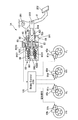
- FIG. 1 is a schematic configuration diagram of a brake control device 1 of Embodiment 1.
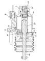
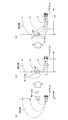
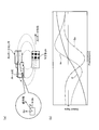
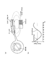
- FIG. FIG. 3 is a sectional view of a main part of a master cylinder 3 of the first embodiment. It is a figure which shows the detection principle of the angle of a magnetic force line by a Hall IC. It is a figure which shows the method of calculating
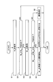
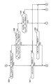
- FIG. 6 is a flowchart showing a flow of processing for setting a standard median value for carrying out the abnormality determination processing of the first embodiment.
- 9 is a characteristic diagram of a standard median value according to a stroke of a push rod 204.
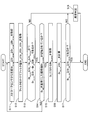
- FIG. 6 is a flowchart showing a flow of abnormality determination processing of the stroke sensor 90 according to the first embodiment.
- FIG. 6 is a diagram showing a relationship between a stroke of a push rod 204 and a stroke calculated from an angle of a magnetic force line acquired from a stroke sensor 90.
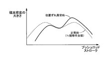
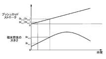
- FIG. 7 is a diagram showing a relationship between a stroke of a push rod 204 and a magnitude of magnetic flux density.
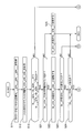
- 9 is a flowchart showing a flow of abnormality determination processing of a stroke sensor 90 according to the second embodiment.
- FIG. 9 is a flowchart showing a flow of abnormality determination processing of a stroke sensor 90 according to the second embodiment.
- 9 is a flowchart showing a flow of abnormality determination processing of a stroke sensor 90 according to the second embodiment.
- 9 is a flowchart showing a flow of abnormality determination processing of a stroke sensor 90 according to the second embodiment.
- 7 is a time chart of the stroke of the push rod 204 and the magnitude of magnetic flux density when the driver depresses the brake pedal 2.
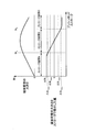
- FIG. 6 is a diagram showing a relationship between the magnitude of the magnetic flux density with respect to the stroke of the push rod 204 and a value obtained by differentiating the magnitude of the magnetic flux density by the stroke.
- FIG. 7 is a schematic configuration diagram of a brake control device 1A according to a third embodiment.
- FIG. 9 is a schematic configuration diagram of a vehicle pedal stroke detection device 1B according to a fourth embodiment.
- FIG. 1 is a schematic configuration diagram of a brake control device 1 of the first embodiment.
- the brake control device 1 is a hydraulic brake control device suitable for an electric vehicle.
- the electric vehicle is a hybrid vehicle including an engine and a motor generator as a prime mover for driving wheels, an electric vehicle including only a motor generator, and the like.
- the brake control device 1 may be applied to a vehicle that uses only the engine as a driving force source.
- the brake control device 1 supplies brake fluid to a wheel cylinder (braking force applying portion) 8 provided on each wheel of the vehicle (left front wheel FL, right front wheel FR, left rear wheel RL, right rear wheel RR) to brake.
- the wheel cylinder 8 may be a cylinder of a hydraulic brake caliper in a disc brake mechanism or a wheel cylinder of a drum brake mechanism.
- the brake control device 1 has two systems, that is, a P (primary) system and an S (secondary) system brake system (brake piping), and adopts, for example, an X piping system.
- Other piping types such as front and rear piping may be adopted.
- the suffixes P and S are added to the end of each symbol.
- the brake pedal 2 is a brake operation member that receives a driver's brake operation input.
- the brake pedal 2 is a so-called hanging type, and its base end is rotatably supported by a shaft 201.
- a pedal pad 202 which is a target to be depressed by the driver.
- One end of a push rod (rod) 204 is rotatably connected by a shaft 203 to the base end side between the shaft 201 and the pedal pad 202 of the brake pedal 2.
- the master cylinder 3 is actuated by the driver's operation of the brake pedal 2 (brake operation) to generate brake fluid pressure (master cylinder fluid pressure Pm).
- the brake control device 1 does not include a negative pressure type booster that boosts or amplifies the brake operating force (depressing force F of the brake pedal 2) by using the intake negative pressure generated by the vehicle engine. Therefore, the brake control device 1 can be miniaturized and is most suitable for an electric vehicle that does not have a negative pressure source (engine in many cases).
- the master cylinder 3 is connected to the brake pedal 2 via the push rod 204, and is supplied with brake fluid from the reservoir tank 4.
- the reservoir tank 4 is a brake fluid source that stores brake fluid, and is a low-pressure portion that is opened to atmospheric pressure.
- a plurality of partition members having a predetermined height are used to form a primary hydraulic chamber space 41P, a secondary hydraulic chamber space 41S, and a pump suction space. It is divided into 42 sections.
- a liquid level sensor 94 for detecting the level of the amount of brake fluid in the reservoir tank is installed in the reservoir tank.
- the liquid level sensor 94 is used to warn a decrease in the liquid level in the reservoir tank 4, is composed of a fixed member and a float member, and discretely detects the liquid level.
- the fixing member is fixed to the inner wall of the reservoir tank 4 and has a switch.
- the switch is provided at a position that has substantially the same height as the liquid level.
- the float member has buoyancy with respect to the brake fluid, and is provided so as to move up and down with respect to the fixed member in accordance with an increase or decrease in the brake fluid amount (fluid level).
- the switch provided on the fixed member switches from the off state to the on state. As a result, a drop in the liquid level is detected.
- the specific mode of the liquid level sensor 94 is not limited to the one that detects the liquid level discretely (switch) as described above, but may be the one that continuously detects the liquid level (analog detection). May be.
- the master cylinder 3 is a tandem type, and has a primary piston 32P and a secondary piston 32S in series as a master cylinder piston that moves in the axial direction according to a brake operation.
- the primary piston 32P is connected to the push rod 204.
- the secondary piston 32S is a free piston type.
- the master cylinder 3 is provided with a stroke sensor 90.
- the stroke sensor 90 outputs a sensor signal corresponding to the movement amount (stroke) of the primary piston 32P as a physical amount correlated with the displacement amount (pedal stroke S) of the brake pedal 2 (push rod 204).
- the displacement amount of the push rod 204 is substantially the same as the displacement amount of the primary piston 32P.
- the stroke sensor 90 is a two-output type sensor that outputs sensor signals in two systems.
- the pedal stroke S corresponds to the amount of axial displacement (stroke) of the push rod 204 or the primary piston 32P multiplied by the pedal ratio K of the brake pedal.
- K is the ratio of S to the stroke of the primary piston 32P, and is set to a predetermined value.
- K can be calculated, for example, by the ratio of the distance from the shaft 201 to the pedal pad 202 to the distance from the shaft 201 to the shaft 203.
- Stroke simulator 5 operates according to the driver's brake operation.
- the stroke simulator 5 generates the pedal stroke S by the brake fluid flowing out of the master cylinder 3 flowing into the stroke simulator 5 in response to the driver's brake operation.
- the brake fluid supplied from the master cylinder 3 causes the piston 52 of the stroke simulator 5 to move axially in the cylinder 50.
- the stroke simulator 5 generates an operation reaction force associated with the driver's braking operation.
- the hydraulic unit 6 is a braking control unit that can generate brake hydraulic pressure independently of the driver's brake operation.
- An electronic control unit (automatic vehicle control unit, hereinafter referred to as ECU) 100 is a control unit that controls the operation of the hydraulic unit 6.
- the hydraulic unit 6 receives the supply of brake fluid from the reservoir tank 4 or the master cylinder 3.
- the hydraulic unit 6 is provided between the wheel cylinder 8 and the master cylinder 3, and can individually supply the master cylinder hydraulic pressure Pm or the control hydraulic pressure to each wheel cylinder 8.
- the hydraulic unit 6 has a motor 72 of a pump (hydraulic pressure source) 7 and a plurality of control valves (the shutoff valve 21 and the like) as hydraulic equipment for generating a control hydraulic pressure.
- the pump 7 draws in brake fluid from a brake fluid source (such as the reservoir tank 4) other than the master cylinder 3 and discharges it toward the wheel cylinder 8.
- the pump 7 is, for example, a plunger pump or a gear pump.
- the pump 7 is commonly used in both systems and is rotationally driven by an electric motor 72 as the same drive source.
- the motor 72 is, for example, a DC motor with a brush or a brushless motor.
- the shutoff valve 21 and the like open and close according to the control signal to switch the communication state of the liquid passage 11 and the like. This controls the flow of brake fluid.
- the hydraulic unit 6 can pressurize the wheel cylinder 8 by the hydraulic pressure generated by the pump 7 in a state where the communication between the master cylinder 3 and the wheel cylinder 8 is cut off.
- the hydraulic unit 6 also includes hydraulic pressure sensors 91 to 93 that detect Pm, Pw, and the discharge pressure of the pump 7.
- the ECU 100 is input with the detection values sent from the stroke sensor 90 and the hydraulic pressure sensors 91 to 93, and the information about the traveling state sent from the vehicle side.
- the ECU 100 performs information processing based on these various kinds of information according to a built-in program. Further, it outputs a command signal to each actuator of the hydraulic unit 6 in accordance with the processing result to control them. Specifically, the opening/closing operation of the shutoff valve 21 and the like and the rotation speed of the motor 72 (that is, the discharge amount of the pump 7) are controlled.
- various brake controls are realized by controlling the wheel cylinder hydraulic pressure Pw of each wheel FL to RR.
- the boost control assists the brake operation by generating a braking force that is insufficient with the driver's brake operation force.
- the anti-lock control suppresses slip (lock tendency) of the wheels FL to RR due to braking.
- Vehicle motion control is vehicle behavior stabilization control (ESC) that prevents skidding and the like.
- the automatic brake control is a follow-up vehicle follow-up control or the like.
- the regenerative cooperative brake control controls the wheel cylinder hydraulic pressure Pw so as to achieve the target deceleration (target braking force) in cooperation with the regenerative brake.
- a primary hydraulic chamber 31P is defined between the pistons 32P and 32S of the master cylinder 3.
- a compression coil spring 33P is installed in the primary hydraulic chamber 31P.
- a secondary hydraulic chamber 31S is defined between the piston 32S and the x-axis positive direction end of the cylinder 30.
- a compression coil spring 33S is installed in the secondary hydraulic chamber 31S.
- a first liquid passage (connection liquid passage) 11 opens in each of the hydraulic chambers 31P and 31S.
- the hydraulic chambers 31P and 31S are connected to the first hydraulic passages 11P and 11S of the hydraulic unit 6 via the pipes 10P and S10S and are provided so as to be able to communicate with the wheel cylinder 8.
- the piston 32 strokes, and the hydraulic pressure Pm is generated as the volume of the hydraulic chamber 31 decreases. Approximately the same Pm is generated in both hydraulic chambers 31P and 31S.
- the brake fluid is supplied from the fluid pressure chamber 31 to the wheel cylinder 8 via the first fluid passage 11.
- the master cylinder 3 can pressurize the wheel cylinders 8a, 8d of the P system by the Pm generated in the primary hydraulic chamber 31P via the liquid path of the P system (first liquid path 11P). Further, the master cylinder 3 can pressurize the wheel cylinders 8b and 8c of the S system by the Pm generated in the secondary hydraulic chamber 31S via the liquid path of the S system (first liquid path 11S).
- FIG. 1 shows a cross section passing through the axis of the cylinder 50 of the stroke simulator 5.
- the cylinder 50 is tubular and has a cylindrical inner peripheral surface.
- the cylinder 50 has a piston housing portion 501 having a relatively small diameter and a spring housing portion 502 having a relatively large diameter.
- a third liquid passage 13 (13A), which will be described later, is always open on the inner peripheral surface of the spring accommodating portion 502.
- the piston 52 is installed on the inner peripheral side of the piston housing portion 501 so as to be axially movable along the inner peripheral surface thereof.
- the piston 52 separates the inside of the cylinder 50 into at least two chambers (a positive pressure chamber 511 and a back pressure chamber 512).
- the positive pressure chamber 511 communicates with the second liquid passage 12, and the back pressure chamber 512 communicates with the liquid passage 13A.
- a piston seal 54 is installed on the outer circumference of the piston 52 so as to extend in the circumferential direction (circumferential direction) of the axis of the piston 52.
- the piston seal 54 is in sliding contact with the inner peripheral surface of the cylinder 50 (piston accommodating portion 501) and seals between the inner peripheral surface of the piston accommodating portion 501 and the outer peripheral surface of the piston 52.
- the piston seal 54 is a separation seal member that liquid-tightly separates the positive pressure chamber 511 and the back pressure chamber 512 by sealing them, and complements the function of the piston 52 as the separation member.
- the spring 53 is a compression coil spring installed in the back pressure chamber 512, and always biases the piston 52 in a direction in which the volume of the positive pressure chamber 511 is reduced.
- the spring 53 can generate a reaction force according to the displacement amount (stroke) of the piston 52.
- the spring 53 has a first spring 531 and a second spring 532.
- the first spring 531 is smaller in diameter and shorter than the second spring 532, and has a smaller wire diameter.
- the spring constant of the first spring 531 is smaller than that of the second spring 532.
- the first and second springs 531 and 532 are arranged in series between the piston 52 and the cylinder 50 (spring accommodating portion 502) via the retainer member 530.
- the first hydraulic passage 11 connects the hydraulic chamber 31 of the master cylinder 3 and the wheel cylinder 8.
- the shutoff valve 21 is a normally-open type proportional valve (opened in a non-energized state) provided in the first liquid passage 11.
- the proportional control valve is a solenoid valve whose valve opening is adjusted according to the current supplied to the solenoid.
- the first liquid passage 11 is separated by the shutoff valve 21 into a liquid passage 11A on the master cylinder 3 side and a liquid passage 11B on the wheel cylinder 8 side.
- the solenoid-in valve (SOL/VIN) 25 is located on the wheel cylinder 8 side (fluid passage 11B) of the shutoff valve 21 in the first fluid passage 11, corresponding to each wheel FL to RR (to the fluid passages 11a to 11d). )
- a normally open proportional control valve provided.
- a bypass liquid passage 110 is provided in parallel with the first liquid passage 11 by bypassing the SOL/VIN 25.
- the bypass fluid passage 110 is provided with a check valve 250 that allows only the flow of brake fluid from the wheel cylinder 8 side to the master cylinder 3 side.
- the suction liquid passage 15 connects the internal liquid reservoir 29 and the suction portion 70 of the pump 7.
- the internal liquid pool 29 is connected to the reservoir tank 4 (pump suction space 42) via the suction pipe 10R.
- the discharge liquid passage 16 connects the discharge portion 71 of the pump 7 and the shutoff valve 21 and the SOL/VIN 25 in the first liquid passage 11B.
- the check valve 160 is provided in the discharge liquid passage 16 and allows only the flow of the brake liquid from the discharge portion 71 side (upstream side) of the pump 7 to the first liquid passage 11 side (downstream side).
- the check valve 160 is a discharge valve included in the pump 7.
- the discharge liquid passage 16 is branched on the downstream side of the check valve 160 into a P-system liquid passage 16P and an S-system liquid passage 16S.
- the liquid paths 16P and 16S are connected to the first liquid path 11P of the P system and the first liquid path 11S of the S system, respectively.
- the liquid paths 16P and 16S connect the first liquid paths 11P and 11S to each other.
- the communication valve 26P is a normally closed (closed in a non-energized state) on/off valve provided in the liquid passage 16P.
- the on-off valve is a solenoid valve whose opening and closing is binaryly controlled.
- the communication valve 26S is a normally closed on/off valve provided in the liquid passage 16S.
- the pump 7 is a second hydraulic pressure source capable of generating a hydraulic pressure in the first hydraulic passage 11 by the brake fluid supplied from the reservoir tank 4 to generate a wheel cylinder hydraulic pressure Pw.
- the pump 7 is connected to the wheel cylinders 8a to 8d via the communication liquid passages (discharge liquid passages 16P, 16S) and the first liquid passages 11P, 11S, and is connected to the communication liquid passages (discharge liquid passages 16P, 16S).
- the wheel cylinder 8 can be pressurized by discharging the brake fluid.
- the first depressurizing liquid passage 17 connects between the check valve 160 and the communication valve 26 in the discharge liquid passage 16 and the suction liquid passage 15.
- the pressure regulating valve 27 is a normally open proportional control valve provided in the first pressure reducing liquid passage 17.
- the pressure regulating valve 27 may be a normally closed type.
- the second depressurizing liquid passage 18 connects the suction liquid passage 15 with the wheel cylinder 8 side of the SOL/V IN 25 in the first liquid passage 11B.
- the solenoid-out valve (SOL/V OUT) 28 is a normally closed on/off valve as a second pressure reducing valve provided in the second pressure reducing liquid passage 18.
- the second liquid passage 12 branches from the first liquid passage 11A of the S system and is connected to the stroke simulator 5.
- the second hydraulic passage 12 connects the secondary hydraulic chamber 31S of the master cylinder 3 and the positive pressure chamber 511 of the stroke simulator 5 together with the first hydraulic passage 11A.
- the third liquid passage 13 connects the back pressure chamber 512 of the stroke simulator 5 and the first liquid passage 11B of the S system. Specifically, the third liquid passage 13 branches from between the shutoff valve 21S and the SOL/V IN 25 in the first liquid passage 11S (liquid passage 11B) and connects to the back pressure chamber 512.
- the stroke simulator in valve SS/V IN23 is a normally closed on/off valve provided in the third fluid passage 13.
- the third liquid passage 13 is separated by the SS/V IN 23 into a liquid passage 13A on the back pressure chamber 512 side and a liquid passage 13B on the first liquid passage 11 side.
- a bypass liquid passage 130 is provided in parallel with the third liquid passage 13 by bypassing the SS/V IN 23.
- the bypass liquid passage 130 connects the liquid passage 13A and the liquid passage 13B.
- a check valve 230 is provided in the bypass liquid passage 130. The check valve 230 allows the flow of the brake fluid from the back pressure chamber 512 side (the fluid path 13A) toward the first fluid path 11 side (the fluid path 13B) and suppresses the brake fluid flow in the opposite direction.
- the fourth liquid passage 14 connects the back pressure chamber 512 of the stroke simulator 5 and the reservoir tank 4.
- the fourth liquid passage 14 is provided between the back pressure chamber 512 and the SS/V IN 23 (the liquid passage 13A) in the third liquid passage 13 and on the suction liquid passage 15 (or on the suction liquid passage 15 side with respect to the pressure regulating valve 27).
- the first depressurizing liquid passage 17 and the second depressurizing liquid passage 18) on the suction liquid passage 15 side of the SOL/V OUT 28 are connected.
- the fourth liquid passage 14 may be directly connected to the back pressure chamber 512 or the reservoir tank 4.
- the stroke simulator out valve (simulator cut valve) SS/V OUT24 is a normally closed on/off valve provided in the fourth fluid passage 14.
- a bypass liquid passage 140 is provided in parallel with the fourth liquid passage 14 by bypassing the SS/V OUT24.
- the bypass fluid passage 140 allows the flow of brake fluid from the reservoir tank 4 (intake fluid passage 15) side toward the third fluid passage 13A side, that is, the back pressure chamber 512 side, and suppresses the reverse flow of brake fluid.
- a check valve 240 is provided. Between the shutoff valve 21S and the master cylinder 3 in the first hydraulic passage 11S (the hydraulic passage 11A), the hydraulic pressure at this location (the master cylinder hydraulic pressure Pm and the hydraulic pressure in the positive pressure chamber 511 of the stroke simulator 5) is applied.
- a fluid pressure sensor 91 for detecting is provided.
- a hydraulic pressure sensor 92 for detecting the hydraulic pressure (wheel cylinder hydraulic pressure Pw) at this location is provided between the shutoff valve 21 and the SOL/V IN 25 in the first hydraulic passage 11. Between the discharge portion 71 (check valve 160) of the pump 7 in the discharge liquid passage 16 and the communication valve 26, a hydraulic pressure sensor 93 that detects the hydraulic pressure at this location (pump discharge pressure) is provided.
- the brake system (first hydraulic passage 11) that connects the hydraulic chamber 31 of the master cylinder 3 and the wheel cylinder 8 with the shutoff valve 21 controlled in the valve opening direction constitutes a first system.
- This first system can realize a pedal effort brake (non-boosting control) by generating the wheel cylinder fluid pressure Pw by the master cylinder fluid pressure Pm generated by using the pedal effort F.
- the brake system including the pump 7 and connecting the reservoir tank 4 and the wheel cylinder 8 (the suction liquid passage 15, the discharge liquid passage 16 and the like) has the second Configure the system.
- the second system constitutes a so-called brake-by-wire device that generates the wheel cylinder hydraulic pressure Pw by the hydraulic pressure generated by using the pump 7, and can realize boost control or the like as brake-by-wire control.
- the stroke simulator 5 generates an operation reaction force associated with the driver's braking operation.
- the ECU 100 includes a by-wire control unit 101, a pedal effort braking unit 102, and a fail safe unit 103.
- the by-wire control unit 101 closes the shutoff valve 21 and pressurizes the wheel cylinder 8 by the pump 7 according to the brake operation state of the driver.
- the by-wire control unit 101 includes a brake operation state detection unit 104, a target wheel cylinder hydraulic pressure calculation unit 105, and a wheel cylinder hydraulic pressure control unit 106.
- the brake operation state detection unit 104 receives the value detected by the stroke sensor 90 and detects the pedal stroke S as the brake operation amount by the driver. Further, the brake operation state detection unit 104 detects whether or not the driver is in the brake operation (whether or not the brake pedal 2 is operated) based on S.
- the master cylinder 3, the first liquid passage 11, the shutoff valve 21, the pump 7, the magnet 96, the stroke sensor 90, and the ECU 100 constitute a pedal stroke detection device for an automobile.
- the target wheel cylinder hydraulic pressure calculation unit 105 calculates the target wheel cylinder hydraulic pressure Pw*.
- the target wheel cylinder hydraulic pressure Pw* that achieves the ideal relationship (brake characteristics) is calculated.
- a predetermined relationship between the pedal stroke S and the wheel cylinder hydraulic pressure Pw (braking force), which is realized when the negative pressure type booster is operated is set.
- the above ideal relationship for calculating the target wheel cylinder hydraulic pressure Pw* is set.
- the wheel cylinder hydraulic pressure control unit 106 controls the shutoff valve 21 in the closing direction to generate the wheel cylinder hydraulic pressure Pw by the pump 7 (second system) (pressurization control). ) Make it possible.
- each actuator of the hydraulic unit 6 is controlled to perform hydraulic control (for example, boost control) that realizes the target wheel cylinder hydraulic pressure Pw*.
- the shutoff valve 21 is controlled in the valve closing direction
- the communication valve 26 is controlled in the valve opening direction
- the pressure regulating valve 27 is controlled in the valve closing direction
- the pump 7 is operated.
- each wheel cylinder 8 is pressurized. That is, the wheel cylinder 8 is pressurized using the hydraulic pressure generated in the first liquid passage 11B by the pump 7.
- the desired control is performed. Power is obtained. That is, the wheel cylinder hydraulic pressure Pw is adjusted by controlling the open state of the pressure regulating valve 27 and appropriately leaking the brake fluid from the discharge liquid passage 16 or the first liquid passage 11 to the suction liquid passage 15 via the pressure regulating valve 27. it can.
- the wheel cylinder hydraulic pressure Pw is controlled by changing the valve opening state of the pressure regulating valve 27 instead of the rotation speed of the pump 7 (motor 72).
- the shut-off valve 21 in the closing direction to shut off the master cylinder 3 side and the wheel cylinder 8 side, it is easy to control the wheel cylinder hydraulic pressure Pw independently from the driver's braking operation. Become. It also controls SS/VOUT24 in the valve opening direction.
- the back pressure chamber 512 of the stroke simulator 5 communicates with the suction liquid passage 15 (reservoir tank 4) side.
- the piston 52 operates.
- the pedal stroke Sp is generated.
- a brake fluid of the same amount as the amount of fluid flowing into the positive pressure chamber 511 flows out from the back pressure chamber 512.
- the brake fluid is discharged to the suction fluid passage 15 (reservoir tank 4) side through the third fluid passage 13A and the fourth fluid passage 14.
- the fourth liquid passage 14 may be connected to the low-pressure portion into which the brake liquid can flow, and does not necessarily have to be connected to the reservoir tank 4.
- the spring 53 of the stroke simulator 5 and the hydraulic pressure of the back pressure chamber 512 push the piston 52 to generate an operation reaction force (pedal reaction force) acting on the brake pedal 2. That is, the stroke simulator 5 generates the characteristic of the brake pedal 2 (FS characteristic that is the relationship of S with respect to F) during the by-wire control.
- the pedal force brake unit 102 opens the shutoff valve 21 and pressurizes the wheel cylinder 8 by the master cylinder 3.
- the hydraulic pressure unit 6 is brought into a state in which the wheel cylinder hydraulic pressure Pw can be generated by the master cylinder hydraulic pressure Pm (first system), and pedal braking is realized. ..
- the stroke simulator 5 is deactivated in response to the driver's brake operation.
- the brake fluid is efficiently supplied from the master cylinder 3 toward the wheel cylinder 8. Therefore, it is possible to suppress a decrease in the wheel cylinder hydraulic pressure Pw generated by the driver by the pedaling force F.
- the pedal effort braking unit 102 deactivates all the actuators in the hydraulic unit 6.
- the SS/VIN23 may be controlled in the valve opening direction.
- the fail safe unit 103 detects the occurrence of an abnormality (failure or failure) in the brake control device 1. For example, failure of the actuator (pump 7 or motor 72, pressure regulating valve 27, etc.) in the hydraulic unit 6 is detected based on the signal from the brake operation state detection unit 104 and the signal from each sensor. Alternatively, it detects an abnormality in the vehicle-mounted power supply (battery) that supplies power to the brake control device 1 or the ECU 100. If the fail-safe unit 103 detects the occurrence of an abnormality during the by-wire control, the fail-safe unit 103 switches the control according to the state of the abnormality.
- an abnormality failure or failure
- failure of the actuator pump 7 or motor 72, pressure regulating valve 27, etc.
- the fail-safe unit 103 switches the control according to the state of the abnormality.
- the pedal effort braking unit 102 is activated to switch the by-wire control to the pedal effort brake. Specifically, all the actuators in the hydraulic unit 6 are deactivated, and the pedal force brake is activated.
- the shutoff valve 21 is a normally open valve, it is possible to automatically realize the pedaling brake by opening the shutoff valve 21 when the power fails.
- the SS/VOUT24 is normally closed, the stroke simulator 5 is automatically deactivated by closing the SS/VOUT24 when the power fails.
- the communication valve 26 is of the normally closed type, the brake hydraulic systems of both systems are independent from each other when the power fails, and the wheel cylinder pressurization by the pedaling force F can be separately performed in each system.
- the fail-safe unit 103 detects the brake system (liquid leak system) in which the liquid leak failure occurs among the two brake systems. Do the action for.
- the fluid leakage point of the brake system is the brake pipe or the like that connects the housing of the fluid pressure unit 6 and the wheel cylinder 8, but the fluid pressure of the brake system also decreases due to open sticking of the SOL/VOUT 28. Therefore, in the first embodiment, a decrease in hydraulic pressure due to open solidification of the SOL/VOUT 28 is also treated as a leak in the brake system.
- the by-wire control unit 101 When the fail-safe unit 103 detects a liquid leakage system, the by-wire control unit 101 performs by-wire control only by the brake system (normal system) in which no liquid leakage failure has occurred (this is called one-system boost control). Call). In the single system boost control, the operations of the shutoff valve 21, the pressure regulating valve 27 and the pump 7 are the same as the normal control (normal by-wire control), but the communication valve 26 on the liquid leakage system side is closed to close the liquid leakage system. Cut off the fluid passage on the side. Thereby, the wheel cylinder hydraulic pressure Pw of the normal system can be controlled.
- FIG. 2 is a cross-sectional view of a main part of the master cylinder 3 of the first embodiment.
- the stroke sensor 90 has a detection unit 95 and a magnet 96.
- the detection unit 95 and the magnet 96 are arranged close to each other.
- the detection unit 95 is attached to the outer peripheral surface of the master cylinder housing 34.
- the detection unit 95 has a Hall IC in which a plurality of Hall elements and operational amplifiers are integrated.
- the Hall IC uses the Hall effect (a phenomenon in which an electromotive force appears in a direction perpendicular to both the current and the magnetic field when a magnetic field is applied in the direction perpendicular to the current flowing through the substance), and the position of the magnet 96, that is, the push The stroke of the rod 204 is detected.
- the Hall IC detects the angle of the magnetic force line and outputs a sensor signal based on the angle of the magnetic force line.
- the magnet 96 is, for example, a neodymium magnet and is fixed to the primary piston 32P via a magnet holder 97 made of synthetic resin.
- the detection unit 95 (the Hall element thereof) and the magnet 96 face each other in the radial direction.
- the magnet holder 97 has an annular portion 98 and a magnet holding portion 99.
- the annular portion 98 is fixed to the end of the primary piston 32P.
- the annular portion 98 is formed in an annular shape, and the push rod 204 penetrates the inner peripheral side.
- the annular portion 98 is restricted from rotating relative to the primary piston 32P by a rotation stopper (not shown).
- the magnet holding portion 99 is located on the outer peripheral side of the annular portion 98 and holds the magnet 96.
- the principle of detecting the angle of the magnetic force line by the Hall IC of the stroke sensor 90 will be described.
- the relative position of the magnet with respect to the Hall IC changes, so the angle (direction) of the magnetic force line passing through the Hall IC changes.
- FIG. 3(a) when the magnet is in the initial position, the angle of the magnetic force line passing through the Hall IC is 0°, but when the magnet strokes by a predetermined value a, the magnetic force line passing through the Hall IC is The angle changes to 90° (Fig. 3(b)).
- the angle of the magnetic force line passing through the Hall IC changes to 120° (Fig. 3(c)). In this way, the angle of the magnetic force line that passes through the Hall IC changes according to the stroke of the magnet, and thus the stroke of the magnet can be detected by determining the angle of the magnetic force line.
- the method of detecting the angle of the magnetic force line by the stroke sensor 90 may be either of the following two methods.
- the first specific example is a method in which the magnitude of magnetic flux density is measured by Hall elements arranged in two directions and the angle of the magnetic force line is obtained by arc tangent calculation. As shown in Fig.
- a Hall element in which electrodes are arranged so as to generate a voltage according to the magnitude Bx of the magnetic flux density in the stroke direction (X direction) of the magnet and the magnetic flux in the radial direction (Z direction) Measuring the voltage between the electrodes of the Hall element corresponding to the X direction and the Hall element corresponding to the Z direction by using the Hall element in which the electrodes are arranged so as to generate the voltage according to the density Bz.
- the magnetic flux density magnitudes Bx and Bz in the X and Z directions are obtained.
- the arc tangent of the value Bx/Bz is calculated by dividing Bx by Bz.
- the angle ⁇ [deg] of the magnetic force lines according to the stroke [mm] as shown in FIG. 4B is obtained. Since the characteristic of the angle ⁇ of the magnetic force line obtained by the arc tangent calculation becomes a curve that increases as the stroke increases, linear correction is performed when using.
- the processing after the arctangent calculation may be performed by the detection unit 95 or the ECU 100. That is, the calculation of the angle ⁇ of the magnetic force line may be performed on the stroke sensor 90 side or the ECU 100 side.
- the second specific example is a method in which the magnitude of magnetic flux density is measured by Hall elements arranged in an annular shape, and the angle of the magnetic force line is obtained at the zero cross point.
- a plurality of Hall elements are arranged in an annular shape, and the voltage value of each electrode (electrode number 0 to 64) is measured.
- FIG. 5B voltage values corresponding to the electrode numbers 0 to 64 are obtained.
- the direction orthogonal to the direction connecting the two points (zero cross points) where the voltage value becomes zero is found, and the angle of the magnetic force line according to the stroke is referred by referring to the sign of the voltage value between the two zero cross points.
- Find ⁇ The processing after the calculation of the zero-cross point may be performed by the detection unit 95 or the ECU 100. That is, the calculation of the angle ⁇ of the magnetic force line may be performed on the stroke sensor 90 side or the ECU 100 side.
- the brake control device 1 of the first embodiment aims at suppressing the deterioration of the detection accuracy of the stroke sensor 90 caused by the relative position between the magnet 96 and the Hall IC deviating from the specified position.
- the stroke detection error (rod of rod)
- FIG. 6 is a flowchart showing a flow of processing for setting a standard median value for carrying out the abnormality determination processing of the first embodiment. This process is performed in a state where the two outputs of the stroke sensor 90 match.
- step S1 the stroke value St0 is acquired from the stroke sensor 90.
- step S2 in order to determine whether the stroke value St0 is the stroke 0 [mm] position (stroke initial value) of the push rod 204, it is determined whether the stroke value St0 is less than or equal to the threshold value Stmin. If YES, the process proceeds to step S3. If NO, this process ends.
- the threshold value Stmin is the dimensional tolerance and assembly error of the master cylinder 3 and the stroke sensor 90, the dimensional error of the stroke sensor 90, the detection error of the stroke sensor 90, the magnetic flux density of the magnet 96 in the stroke 0 [mm] of the push rod 204. It is a value obtained by adding the angle error of.
- step S3 the magnitude Brst0 of the magnetic flux density at the stroke value St0 is acquired from the stroke sensor 90.
- step S4 in order to confirm the soundness of the magnetic flux density magnitude Brst0 of the stroke sensor 90, it is determined whether the magnetic flux density magnitude Brst0 is equal to or higher than the lower threshold Brst0_min and equal to or lower than the upper threshold Brst0_max (>Brst0_min). If YES, the process proceeds to step S5, and if NO, the process proceeds to step S6.
- the lower limit threshold Brst0_min and the upper limit threshold Brst0_max are thresholds of the magnetic flux density of the stroke sensor 90 at the stroke 0 [mm] position of the push rod 204.
- this threshold value is set based on the size error of the magnetic flux density of the magnet 96 due to temperature and durability deterioration.
- the standard median value Brtol_center corresponding to the stroke is set based on the characteristic of the magnitude of the magnetic flux density with respect to the stroke with Brst0 as a reference and stored in the memory.
- the characteristic of the magnitude of the magnetic flux density with respect to the stroke is a characteristic previously obtained by experiments based on the relationship between the stroke and the magnitude of the magnetic flux density when the relative position between the magnet 96 and the Hall IC is at the specified position. , Stored in memory.
- FIG. 7 is a characteristic diagram of the standard median value Brtol_center according to the stroke of the push rod 204.
- the characteristic of the standard median value Brtol_center according to the stroke is a wave-shaped curve with three inflection points, and between the two regions that are convex toward the side with a large magnetic flux density, the side with a small magnetic flux density It has a shape in which a convex region is sandwiched.
- FIG. 8 is a flowchart showing the flow of abnormality determination processing for the stroke sensor 90 according to the first embodiment.
- step S11 the stroke raw values Stx1_raw, Stx2_raw and the magnetic flux density magnitude raw values Brx1_raw, Brx2_raw are acquired from the stroke sensor 90.
- step S12 the acquired stroke raw values Stx1_raw, Stx2_raw and the magnetic flux density magnitude raw values Brx1_raw, Brx2_raw are filtered to obtain the stroke filter values Stx1, Stx2 and the magnetic flux density magnitude filter values Brx1, Brx2. ..
- step S13 the difference (Stx1-Stx2) between the filter values Stx1 and Stx2 of the two strokes is greater than or equal to the lower threshold value Stred_min and less than or equal to the upper threshold value Stred_max(>Stred_min), and the two magnetic flux density magnitude filter values Brx1, It is determined whether the difference (Brx1-Brx2) of Brx2 is not less than the lower limit threshold Brred_min and not more than the upper limit threshold Brred_max(>Brred_min). If YES, the process proceeds to step S14, and if NO, the process proceeds to step S18.
- Step S13 is a step of determining that there is no abnormality in the stroke sensor 90 excluding the positional deviation abnormality.
- step S14 it is determined whether the standard median value Brtol_center according to the stroke set in step S5 of FIG. 3 is stored in the memory. If YES, the process proceeds to step S15, and if NO, the process returns to step S11.
- step S15 the standard median value Brtol_center at the stroke filter value Stx (Stx1 or Stx2) is acquired based on the standard median value Brtol_center corresponding to the stroke.
- step S16 a standard upper limit value Brtol_max and a standard lower limit value Brtol_min are calculated from the standard median value Brtol_center.
- the calculation method is performed by adding the detection error of the stroke sensor 90, the temperature error of the magnet 96 and the size error of the magnetic flux density due to deterioration of durability to the standard value Brtol_center.
- the standard upper limit value Brtol_max and the standard lower limit value Brtol_min have a wave shape obtained by vertically offsetting the standard median value Brtol_center.
- step S17 it is determined whether the magnitude filter value Brstx (Brx1 or Brx2) of the magnetic flux density is equal to or higher than the standard lower limit value Brtol_min and equal to or lower than the standard upper limit value Brtol_max. If YES, the process ends, and if NO, the process proceeds to step S18. In step S18, it is determined that the stroke sensor 90 has an abnormality, and this control ends.
- the relative position between the magnet and the Hall IC may shift from the specified position during assembly or during traveling.
- the angle of the magnetic force line that the Hall IC receives at a certain stroke position is different from the angle of the magnetic force line that the Hall IC receives when the relative position is at the specified position. ..
- the relative positional deviation causes deterioration of stroke detection accuracy and makes it impossible to continue hydraulic pressure control by by-wire control. Therefore, for example, fail-safe such as switching from by-wire control to pedaling force brake is necessary.
- FIG. 9 is a diagram showing the relationship between the stroke of the push rod 204 (push rod stroke) and the stroke calculated from the angle of the magnetic force lines acquired from the stroke sensor 90 (stroke sensor stroke).
- the stroke sensor stroke deviates from the push rod stroke, but it cannot be judged only from the value of the stroke sensor stroke whether or not the stroke sensor stroke has a correct value.
- the ECU 100 acquires the magnitude raw values Brx1_raw and Brx2_raw of the magnetic flux density from the stroke sensor 90 in addition to the stroke raw values Stx1_raw and Stx2_raw.
- the ECU 100 filters the obtained magnetic flux density magnitude raw values Brx1_raw and Brx2_raw, and compares the magnetic flux density magnitude filter value Brstx with a preset standard median value Brtol_center.
- FIG. 10 is a diagram showing the relationship between the stroke of the push rod 204 and the magnitude of magnetic flux density.
- the positional deviation abnormality occurs, the characteristic of the magnitude of the magnetic flux density with respect to the push rod stroke shows the characteristic at the normal time, that is, the characteristic deviated from the characteristic of the standard median value Brtol_center with respect to the push rod stroke. Therefore, the positional deviation abnormality can be detected by looking at the deviation of the filter value Brstx with respect to the standard median value Brtol_center. As a result, deterioration of the detection accuracy of the stroke sensor 90 can be suppressed, and the detection accuracy of the pedal stroke S can be improved. Further, the reliability of the vehicle pedal stroke detection device can be improved by determining the positional deviation abnormality based on the comparison between the magnitude filter value Brstx of the magnetic flux density and the standard median value Brtol_center.
- the positional deviation abnormality can be detected regardless of the presence/absence of the brake operation. That is, even if the driver is not stepping on the brake pedal 2 (the state where the push rod 204 is not stroking), the positional deviation abnormality can be detected.
- the ECU 100 determines whether the magnitude filter value Brstx of the magnetic flux density is equal to or higher than the standard lower limit value Brtol_min and is equal to or lower than the standard upper limit value Brtol_max.
- the stroke sensor 90 has a predetermined detection error, and the magnet 96 has a magnetic flux density magnitude error due to temperature change or durability deterioration. By setting the standard value in consideration of these errors, the positional deviation abnormality can be detected with higher accuracy.
- the ECU 100 calculates the standard median value Brtol_center according to the stroke based on the magnitude Brst0 of the magnetic flux density at the initial stroke value.
- the standard median value Brtol_center can be set in a state in which the driver has not stepped on the brake pedal 2 before starting the vehicle, so that the positional deviation abnormality can be detected before the brake operation is performed.
- the ECU 100 determines the abnormality of the magnetic flux density magnitude Brst0 at the initial stroke value based on whether or not the magnitude Brst0 of the magnetic flux density at the initial stroke value is not less than the lower limit threshold value Brst0_min and not more than the upper limit threshold value Brst0_max.
- the stroke sensor 90 has a predetermined detection error, and the magnet 96 has a magnetic flux density magnitude error due to temperature change or durability deterioration.
- the ECU 100 detects the positional deviation abnormality regardless of whether or not the brake is operated. In other words, even if the brake pedal 2 is in the non-operated state, the positional deviation abnormality can be detected. Therefore, when the positional deviation abnormality is detected, the by-wire control is switched to the pedaling force brake before the brake operation is performed, so that the safety Can be improved.
- the stroke sensor 90 is a two-output type, and the ECU 100 uses the difference between two stroke stroke filter values Stx1 and Stx2 (Stx1-Stx2) and the difference between two magnetic flux density magnitude filter values Brx1 and Brx2 (Brx1-Brx2). Based on this, an abnormality of the stroke sensor 90 is determined.
- the vehicle pedal stroke detection device detects the stroke of the brake pedal 2 in the brake control device 1.
- the brake control device 1 generates the target wheel cylinder hydraulic pressure of each wheel cylinder 8 based on the stroke of the brake pedal 2 detected by the stroke sensor 90, and operates the pump 7 so that the target wheel cylinder hydraulic pressure is obtained. It is a brake-by-wire device. Therefore, by detecting the positional deviation abnormality of the stroke sensor 90, the control accuracy of the by-wire control can be improved, and a braking force more matched to the driver's braking intention can be realized.
- step S21 it is determined whether or not the first stroke value Stx1_1 and the magnetic flux density magnitude Brx1_1 are stored. If YES, the process proceeds to step S13, and if NO, the process proceeds to step S18.
- step S22 the stroke value Stx1 at the first point and the magnitude Brx1_1 of the magnetic flux density are stored in the memory as the stroke value Stx1_2 at the second point and the magnitude Brx1_2 of the magnetic flux density.
- the stored output of the stroke sensor 90 may be the other stroke value Stx2 of the redundant output and the magnitude Brx2 of the magnetic flux density, but it is preferable to make it the same as the output stored at the first point.
- a step S23 decides whether or not the stroke value Stx1_2 of the second point has changed from the stroke value Stx1_1 of the first point. If YES, the process proceeds to step S24, and if NO, the process proceeds to step S37.
- a step S24 decides whether or not the interval Stx1_1-Stx1_2 between the two stroke values is equal to or larger than the threshold value Stwidth. If YES, the process proceeds to S26, and if NO, this process ends.
- the threshold value Stwidth is set so that ⁇ Brx is a calculated stroke value interval.
- the stroke value Stx1 is stored in the memory as Stx1_1 and the magnitude of magnetic flux density Brx1 is stored in Brx1_1.
- the stored output of the stroke sensor 90 may be the other stroke value Stx2 of two outputs and the magnitude Brx2 of the magnetic flux density.
- step S26 it is determined whether the stroke values Stx1_1 and Stx1_2 stored in the memory are both smaller than the threshold value Sta. If YES, the process proceeds to step S27, and if NO, the process proceeds to step S28.
- This step is a step of determining whether both the stroke values Stx1_1 and Stx1_2 are in the stroke section A in the stroke range of the push rod 204.
- the threshold value Sta is a waveform of the magnetic flux density based on the dimensional tolerance and assembly error between the master cylinder 3 and the stroke sensor 90, the dimensional error of the stroke sensor 90, the detection error of the stroke sensor 90, and the error of the magnetic flux density of the magnet 96. It is set by calculating from the stroke position in the section where is convex.
- step S27 it is determined whether or not the value ⁇ Brx obtained by differentiating the magnitude of the magnetic flux density by the stroke is equal to or larger than the standard value ⁇ Br+Amin. If YES, the process proceeds to step S36, and if NO, the process proceeds to step S18. This step is a step of determining whether ⁇ Brx is within the range assumed in the stroke section A. In step S28, it is determined whether one of the stroke values Stx1_1 and Stx1_2 stored in the memory is smaller than the threshold value Sta and the other is equal to or more than the threshold value Sta and less than the threshold value Stb(>Sta).
- step S29 is a step of determining whether one of the stroke values Stx1_1 and Stx1_2 is in the stroke section A and the other is in the stroke section B.
- the threshold value Stb is a waveform of the magnetic flux density from the dimensional tolerance and assembly error of the master cylinder 3 and the stroke sensor 90, the dimensional error of the stroke sensor 90, the detection error of the stroke sensor 90, and the error of the magnetic flux density of the magnet 96. It is set by calculating from the stroke position in the section where is convex.
- step S29 it is determined whether or not the value ⁇ Brx obtained by differentiating the magnitude of the magnetic flux density by the stroke is equal to or larger than the standard value ⁇ Br-Bmin. If YES, the process proceeds to step S36, and if NO, the process proceeds to step S18.
- This step is a step of determining whether or not ⁇ Brx is within the range assumed in the section extending over the stroke section A and the stroke section B.
- step S30 it is determined whether the stroke values Stx1_1 and Stx1_2 stored in the memory are both equal to or greater than the threshold value Sta and equal to or less than the threshold value Stb. If YES, the process proceeds to step S31, and if NO, the process proceeds to step S32.
- This step is a step of determining whether both the stroke values Stx1_1 and Stx1_2 are in the stroke section B in the stroke range of the push rod 204.
- step S31 it is determined whether or not the value ⁇ Brx obtained by differentiating the magnitude of the magnetic flux density by the stroke is equal to or greater than the standard value ⁇ Br-Bmin and equal to or less than the standard value ⁇ Br+Bmin.
- step S36 determines whether ⁇ Brx is within the range assumed in the stroke section B.
- step S32 it is determined whether one of the stroke values Stx1_1 and Stx1_2 stored in the memory is equal to or larger than the threshold value Sta and smaller than the threshold value Stb, and the other is equal to or larger than the threshold value Stb.
- This step is a step of determining whether one of the stroke values Stx1_1 and Stx1_2 is in the stroke section B and the other is in the stroke section C.
- step S33 it is determined whether or not the value ⁇ Brx obtained by differentiating the magnitude of the magnetic flux density by the stroke is equal to or less than the standard value ⁇ Br+Bmin. If YES, the process proceeds to step S36, and if NO, the process proceeds to step S18.
- This step is a step of determining whether or not ⁇ Brx is within the range assumed in the section extending over the stroke section B and the stroke section C.
- step S34 it is determined whether the stroke values Stx1_1 and Stx1_2 stored in the memory are both equal to or larger than the threshold value Stb. If YES, the process proceeds to step S35, and if NO, the process proceeds to step S36.
- This step is a step of determining whether both the stroke values Stx1_1 and Stx1_2 are in the stroke section C in the stroke range of the push rod 204.
- step S35 it is determined whether the value ⁇ Brx obtained by differentiating the magnitude of the magnetic flux density by the stroke is equal to or less than the standard value ⁇ Br-Cmin. If YES, the process proceeds to step S36, and if NO, the process proceeds to step S18.
- This step is a step of determining whether ⁇ Brx is within the range assumed in the stroke section C.
- step S36 the stroke value Stx1_2 at the second point and the magnitude Brx1_2 of the magnetic flux density are stored in the memory as the stroke value Stx1 at the first point and the magnitude Brx1 of the magnetic flux density.
- step S37 it is determined whether the difference Brx1-Brx2 in the magnitude of the magnetic flux density is equal to or higher than the standard lower limit value Brtol_min and equal to or lower than the standard upper limit value Brtol_max. If YES, the process proceeds to step S36, and if NO, the process proceeds to step S18.
- FIG. 15 is a time chart of the stroke of the push rod 204 and the magnitude of the magnetic flux density when the driver depresses the brake pedal 2.
- ECU100 the value ⁇ Brx ⁇ (Brx1_2-Brx1_1)/(Stx1_2-Stx1_1) which is the value obtained by differentiating the magnitude of the magnetic flux density by the stroke from the magnitudes of the magnetic flux density Brx1-2, Brx1_1 when the stroke value changes from Stx1_1 to Stx1_2. ⁇ Is asked.
- the ECU 100 determines in which stroke section the stroke values Stx1_1, Stx1_2 are in the stroke range of the push rod 204, and the preset value is the standard value of the magnitude of the magnetic flux density assumed in the stroke section. , And a value ⁇ Brx obtained by differentiating the magnitude of the magnetic flux density by the stroke.
- FIG. 16 is a diagram showing the relationship between the magnitude of the magnetic flux density with respect to the stroke of the push rod 204 and the value obtained by differentiating the magnitude of the magnetic flux density by the stroke.
- the characteristic of the magnitude of the magnetic flux density detected by the Hall IC with respect to the stroke is set to be a curve that is convex on the side where the magnetic flux density is large.
- the positional deviation abnormality When the positional deviation abnormality occurs, the characteristic of the value ⁇ Brx obtained by differentiating the magnitude of the magnetic flux density with respect to the push rod stroke by the stroke shows a characteristic that deviates from the characteristic at the normal time. Therefore, the positional deviation abnormality can be detected by comparing the standard value and ⁇ Brx. As an example, when the stroke values Stx1_1, Stx1_2 are in the stroke section A, when the positional deviation abnormality does not occur, the value ⁇ Brx obtained by differentiating the magnitude of the magnetic flux density by the stroke is the standard value ⁇ Br+Amin or more. Therefore, if ⁇ Brx is less than ⁇ Br+Amin, it can be determined that the positional deviation abnormality has occurred.
- the second embodiment by comparing the change rates of the magnetic flux densities, erroneous detection due to sensor noise or the like can be suppressed, and the accuracy of the misregistration determination can be improved, compared with the case of comparing the magnetic flux density magnitudes. ..
- the position is determined based on the comparison between the difference Brx1-Brx2 in the magnitude of the magnetic flux density and the standard values Brtol_min, Brtol_max. Determine the misalignment. That is, when the value ⁇ Brx obtained by differentiating the magnitude of the magnetic flux density by the stroke cannot be obtained, the positional deviation abnormality can be determined before the brake pedal 2 is operated by comparing the magnitudes of the magnetic flux densities.
- the characteristic of the magnitude of the magnetic flux density detected by the Hall IC with respect to the stroke of the push rod 204 is set so as to be a curve that is convex on the side where the magnetic flux density is large.
- the rate of change of the magnitude of the magnetic flux density with respect to the stroke change hardly changes. It is difficult.
- the rate of change of the magnitude of the magnetic flux density with respect to the stroke change greatly changes. It can be set, and the misalignment can be determined with high accuracy.
- FIG. 17 is a schematic configuration diagram of the brake control device 1A of the third embodiment.
- the brake control device 1A is an electric brake control device.
- Each wheel FL to RR is provided with a disc brake type electric caliper 80.
- the ECU 100 rotationally drives the electric motor 81 based on the stroke of the piston body 821 (displacement amount of the push rod 204) detected by the stroke sensor 90, thereby operating the electric caliper 80 and controlling each wheel FL to RR. Give power.
- the structure of the stroke sensor 90 is the same as that of the first embodiment.
- the push rod 204 is connected to the piston body 821.
- the stroke simulator 83 has a cylinder 84, a piston 82, a spring 85, and a rubber damper 86.
- the cylinder 84 has a cylinder body 841 having a cylindrical inner peripheral surface and a plug 842.
- the piston 82 has a piston body 821 and a stem 822.
- the spring 85 is a compression coil spring.
- the rubber damper 86 is a rubber elastic body having a hollow shape.
- the plug 842 is screwed into the open end of the cylinder body 841 and constitutes a part of the cylinder 84.
- the stem 822 has a shaft member 8221 and a retainer 8223.
- the shaft member 8221 penetrates the hole 8222 of the retainer 8223.
- the retainer 8223 is movable in the axial direction of the cylinder 84 with respect to the shaft member 8221.
- the cylinder body 841 has a housing portion 8411 that houses the piston body 82.
- the plug 842 has a housing portion 8421 that houses the stem 822 and the rubber damper 86.
- Two guide members (a bush, a thrust bearing, etc.) 87 that smoothly support the axial movement of the piston 82 are installed on the outer periphery of the piston 82.
- the guide member 87 contacts the inner peripheral surface of the housing portion 8411 and seals between the inner peripheral surface of the housing portion 8411 and the outer peripheral surface of the piston body 821.
- the spring 85 biases the piston body 82 toward the push rod 204.
- the spring 85 generates a reaction force according to the amount of compression.
- the spring 85 is arranged between the piston body 82 and the retainer 8223.
- the retainer 8223 which receives the biasing force of the spring 85, engages with the shaft member 8221 fixed to the piston body 82, and is restricted from further moving.
- the rubber damper 86 is inserted into the housing portion 8421 formed in the plug 842 such that the outer peripheral surface of the rubber damper 86 is in pressure contact with the inner peripheral surface of the housing portion 8421.
- the rubber damper 86 is arranged between the retainer 8223 of the stem 822 and the plug 842.
- the rubber damper 86 generates a reaction force according to the amount of compression.
- the rubber damper 86 is positioned and held by being pressed against the inner peripheral surface of the housing portion 8421.
- the outer peripheral surface of the shaft member 8221 inserted into the through hole 861 of the rubber damper 86 is separated from the inner peripheral surface of the through hole 861 by a predetermined distance.
- the spring 85 and the rubber damper 86 are arranged in series between the piston body 82 and the plug 842 via the retainer 8223.
- the spring constant of the spring 85 is much smaller than that of the rubber damper 86.
- the stroke simulator 83 operates in response to the driver's brake operation, and applies a reaction force and a stroke to the brake pedal 2.
- the ECU 100 executes the abnormality determination process shown in the first or second embodiment on the stroke sensor 90. As a result, the positional deviation abnormality of the stroke sensor 90 can be detected, and the same effect as that of the first or second embodiment can be obtained.
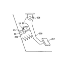
- FIG. 18 is a schematic configuration diagram of a vehicle pedal stroke detection device 1B of the fourth embodiment.
- the accelerator pedal 205 is an accelerator operation member that receives an accelerator operation input from a driver.
- the accelerator pedal 205 is a so-called hanging type, and its base end is rotatably supported by a shaft 206.
- a pedal pad 207 At the tip of the accelerator pedal 205, there is provided a pedal pad 207 which is a target to be depressed by the driver.
- One end of a push rod (rod) 208 is connected between the shaft 206 of the accelerator pedal 205 and the pedal pad 207.
- the other end of the push rod 208 is connected to one end of a piston (not shown) that is axially movable inside the cylinder 209.
- the cylinder 209 is provided with a stroke sensor 90.
- the stroke sensor 90 outputs a sensor signal corresponding to the movement amount (stroke) of the piston to the engine control unit (not shown) as a physical amount that correlates with the displacement amount (accelerator stroke) of the accelerator pedal 205 (push rod 208).
- the structure of the stroke sensor 90 is the same as that of the first embodiment.
- the engine control unit performs the abnormality determination process shown in the first or second embodiment on the stroke sensor 90. As a result, the positional deviation abnormality of the stroke sensor 90 can be detected, and the same effect as that of the first or second embodiment can be obtained.
- the embodiment for carrying out the present invention has been described above, but the specific configuration of the present invention is not limited to the configuration of the embodiment, and there are design changes and the like within the scope not departing from the gist of the invention.
- the physical quantity related to the magnitude of the magnetic flux density detected by the stroke sensor is not limited to the magnitude of the magnetic flux density or its change rate.
- the layout, shape, and number of magnets and Hall ICs are not limited to the embodiment.
- the magnet is provided in parallel with the piston described in International Publication No. 2009/129887.
- the characteristic of the magnitude of the magnetic flux density detected by the Hall IC with respect to the stroke of the push rod 204 may be the standard median characteristic with respect to the stroke shown in FIG. 7.
- a plurality of magnets may be mounted to increase the inflection point.
- an automobile pedal stroke detection device is a stroke sensor that detects a magnet that is displaced in the axial direction in response to movement of a rod that is moved in the axial direction by operating a pedal, and a physical quantity related to a magnetic flux of the magnet.
- a control unit which acquires a physical quantity relating to the magnetic flux of the magnet output from the stroke sensor, and based on the obtained physical quantity relating to the magnetic flux of the magnet, the magnitude of the magnetic flux density of the magnet with respect to the displacement of the rod.
- a first value which is a physical quantity relating to the magnetic field compares the first value with a second value which is a physical quantity relating to the magnitude of the magnetic flux density of the magnet with respect to a preset displacement of the rod.
- the control unit determines an abnormality relating to the displacement of the rod based on a comparison between the first value and the second value.
- the first value is the magnitude of the acquired magnetic flux density of the magnet
- the second value is the preset displacement of the rod. Is the magnitude of the magnetic flux density of the magnet with respect to.
- control unit is configured to detect an abnormality regarding displacement of the rod based on whether the first value is within a predetermined range including the second value. To judge.
- control unit obtains the second value based on the magnitude of the magnetic flux density of the magnet with respect to the preset stroke initial value of the rod.
- control unit is configured to set the magnet to the stroke initial value based on whether the first value in the stroke initial value is within the predetermined range. The abnormality of the magnetic flux density is determined.
- the control unit determines an abnormality regarding displacement of the rod when the pedal is in a non-operated state.
- the first value is a change rate of the magnitude of the magnetic flux density of the acquired magnet
- the second value is the preset value. It is the rate of change of the magnitude of the magnetic flux density of the magnet with respect to the displacement of the rod.
- the control unit when the first value is not obtained, the magnitude of the magnetic flux density of the acquired magnet and the preset rod. The abnormality relating to the displacement of the rod is determined based on the comparison with the magnitude of the magnetic flux density of the magnet with respect to the displacement.
- the magnetic flux density of the magnet with respect to the preset displacement of the rod is convex to a side where the magnitude of the magnetic flux density is large or convex to a side where the magnitude of the magnetic flux density is small.
- the stroke sensor has two outputs, and the control unit determines an abnormality of the stroke sensor based on a difference between the values of the two outputs.
- the pedal is a brake pedal.
- a master cylinder having a piston connected to the rod and a cylinder in which the piston is arranged, and a braking force to wheels according to brake fluid pressure.
- a connecting fluid passage connecting the braking force imparting portion to be applied, a shutoff valve provided in the connecting fluid passage, and a fluid passage between the shutoff valve of the connecting fluid passage and the braking force imparting portion.
- a hydraulic pressure source for supplying the brake fluid to the.
- the automobile control unit outputs the stroke sensor that detects a physical quantity related to the magnetic flux of the magnet that is displaced in the axial direction according to the movement of the rod that is moved in the axial direction by operating the pedal.
- a physical quantity related to the magnetic flux of the magnet is acquired, and a first value that is a physical quantity related to the magnitude of the magnetic flux density of the magnet with respect to the displacement of the rod is obtained based on the acquired physical quantity related to the magnetic flux of the magnet, and the first value is obtained.
- a second value which is a physical quantity related to the magnitude of the magnetic flux density of the magnet with respect to the displacement of the rod set in advance.
- the abnormality relating to the displacement of the rod is determined based on the comparison between the first value and the second value.
- the present invention is not limited to the above-described embodiment, and various modifications are included.
- the above-described embodiments have been described in detail in order to explain the present invention in an easy-to-understand manner, and are not necessarily limited to those including all the configurations described.
- a part of the configuration of one embodiment can be replaced with the configuration of another embodiment, and the configuration of another embodiment can be added to the configuration of one embodiment.
Landscapes
- Engineering & Computer Science (AREA)
- Physics & Mathematics (AREA)
- General Physics & Mathematics (AREA)
- Transportation (AREA)
- Mechanical Engineering (AREA)
- Automation & Control Theory (AREA)
- Condensed Matter Physics & Semiconductors (AREA)
- Regulating Braking Force (AREA)
- Measuring Magnetic Variables (AREA)
- Valves And Accessory Devices For Braking Systems (AREA)
- Braking Elements And Transmission Devices (AREA)
- Mechanical Control Devices (AREA)
Abstract
ストロークセンサから出力されたマグネットの磁束に関する物理量に基づいてプッシュロッドの変位に対するマグネットの磁束密度の大きさに関する物理量である第1の値を求め、第1の値と、予め設定されたプッシュロッドの変位に対するマグネットの磁束密度の大きさに関する物理量である第2の値と、を比較する。
Description
本発明は、自動車用ペダルストローク検出装置および自動車用コントロールユニットに関する。
特許文献1には、マスタシリンダのピストンに設けられたマグネットと、マグネットと対向して設けられたストロークセンサと、によりブレーキペダルのストロークを検出する自動車用ペダルストローク検出装置が開示されている。
しかしながら、上記特許文献1に記載の自動車用ペダルストローク検出装置にあっては、ホールICが受ける磁力線に基づきマグネットのストロークを検出しているため、マグネットとホールICとの相対位置が規定位置からずれることにより、ストロークの検出精度が悪化するおそれがあった。
本発明の目的の一つは、ストロークセンサの検出精度の悪化を抑制できる自動車用ペダルストローク検出装置および自動車用コントロールユニットを提供することにある。
本発明の一実施形態における自動車用ペダルストローク検出装置は、ストロークセンサから出力されたマグネットの磁束に関する物理量に基づいてロッドの変位に対するマグネットの磁束密度の大きさに関する物理量である第1の値を求め、第1の値と、予め設定されたロッドの変位に対するマグネットの磁束密度の大きさに関する物理量である第2の値と、を比較する。
本発明の一実施形態における自動車用ペダルストローク検出装置は、ストロークセンサから出力されたマグネットの磁束に関する物理量に基づいてロッドの変位に対するマグネットの磁束密度の大きさに関する物理量である第1の値を求め、第1の値と、予め設定されたロッドの変位に対するマグネットの磁束密度の大きさに関する物理量である第2の値と、を比較する。
よって、本発明の一実施形態によれば、ストロークセンサの検出精度の悪化を抑制できる。
〔実施形態1〕
図1は、実施形態1のブレーキ制御装置1の概略構成図である。ブレーキ制御装置1は、電動車両に好適な液圧式ブレーキ制御装置である。電動車両は、車輪を駆動する原動機として、エンジンのほかモータジェネレータを備えたハイブリッド車や、モータジェネレータのみを備えた電気自動車等である。なお、エンジンのみを駆動力源とする車両にブレーキ制御装置1を適用してもよい。ブレーキ制御装置1は、車両の各車輪(左前輪FL、右前輪FR、左後輪RL、右後輪RR)に設けられたホイルシリンダ(制動力付与部)8にブレーキ液を供給してブレーキ液圧(ホイルシリンダ液圧Pw)を発生させる。このホイルシリンダ液圧Pwにより摩擦部材を移動させ、摩擦部材を車輪側の回転部材に押し付けることで、摩擦力を発生させる。これにより、各車輪FL~RRに制動力を付与する。ここで、ホイルシリンダ8は、ディスクブレーキ機構における油圧式ブレーキキャリパのシリンダのほか、ドラムブレーキ機構のホイルシリンダであってもよい。ブレーキ制御装置1は、2系統すなわちP(プライマリ)系統およびS(セカンダリ)系統のブレーキ系統(ブレーキ配管)を有しており、例えばX配管形式を採用している。なお、前後配管等、他の配管形式を採用してもよい。以下、P系統に対応して設けられた部材とS系統に対応する部材とを区別する場合は、それぞれの符号の末尾に添字P,Sを付す。
図1は、実施形態1のブレーキ制御装置1の概略構成図である。ブレーキ制御装置1は、電動車両に好適な液圧式ブレーキ制御装置である。電動車両は、車輪を駆動する原動機として、エンジンのほかモータジェネレータを備えたハイブリッド車や、モータジェネレータのみを備えた電気自動車等である。なお、エンジンのみを駆動力源とする車両にブレーキ制御装置1を適用してもよい。ブレーキ制御装置1は、車両の各車輪(左前輪FL、右前輪FR、左後輪RL、右後輪RR)に設けられたホイルシリンダ(制動力付与部)8にブレーキ液を供給してブレーキ液圧(ホイルシリンダ液圧Pw)を発生させる。このホイルシリンダ液圧Pwにより摩擦部材を移動させ、摩擦部材を車輪側の回転部材に押し付けることで、摩擦力を発生させる。これにより、各車輪FL~RRに制動力を付与する。ここで、ホイルシリンダ8は、ディスクブレーキ機構における油圧式ブレーキキャリパのシリンダのほか、ドラムブレーキ機構のホイルシリンダであってもよい。ブレーキ制御装置1は、2系統すなわちP(プライマリ)系統およびS(セカンダリ)系統のブレーキ系統(ブレーキ配管)を有しており、例えばX配管形式を採用している。なお、前後配管等、他の配管形式を採用してもよい。以下、P系統に対応して設けられた部材とS系統に対応する部材とを区別する場合は、それぞれの符号の末尾に添字P,Sを付す。
ブレーキペダル2は、ドライバのブレーキ操作の入力を受けるブレーキ操作部材である。ブレーキペダル2はいわゆる吊り下げ型であり、その基端が軸201によって回転自在に支持されている。ブレーキペダル2の先端には、ドライバが踏み込む対象となるペダルパッド202が設けられている。ブレーキペダル2の軸201とペダルパッド202との間における基端側には、プッシュロッド(ロッド)204の一端が、軸203によって回転自在に接続されている。
マスタシリンダ3は、ドライバによるブレーキペダル2の操作(ブレーキ操作)により作動し、ブレーキ液圧(マスタシリンダ液圧Pm)を発生する。なお、ブレーキ制御装置1は、車両のエンジンが発生する吸気負圧を利用してブレーキ操作力(ブレーキペダル2の踏力F)を倍力または増幅する負圧式の倍力装置を備えていない。このため、ブレーキ制御装置1を小型化可能であり、かつ、負圧源(多くの場合はエンジン)を有さない電動車両に最適である。マスタシリンダ3は、プッシュロッド204を介してブレーキペダル2に接続されると共に、リザーバタンク4からブレーキ液を補給される。
マスタシリンダ3は、ドライバによるブレーキペダル2の操作(ブレーキ操作)により作動し、ブレーキ液圧(マスタシリンダ液圧Pm)を発生する。なお、ブレーキ制御装置1は、車両のエンジンが発生する吸気負圧を利用してブレーキ操作力(ブレーキペダル2の踏力F)を倍力または増幅する負圧式の倍力装置を備えていない。このため、ブレーキ制御装置1を小型化可能であり、かつ、負圧源(多くの場合はエンジン)を有さない電動車両に最適である。マスタシリンダ3は、プッシュロッド204を介してブレーキペダル2に接続されると共に、リザーバタンク4からブレーキ液を補給される。
リザーバタンク4は、ブレーキ液を貯留するブレーキ液源であり、大気圧に開放される低圧部である。リザーバタンク4の内部における底部側(鉛直方向下側)は、所定の高さを有する複数の仕切部材により、プライマリ液圧室用空間41Pと、セカンダリ液圧室用空間41Sと、ポンプ吸入用空間42とに区画(画成)されている。リザーバタンク内には、リザーバタンク内ブレーキ液量のレベルを検出する液面センサ94が設置されている。液面センサ94は、リザーバタンク4内の液面低下を警報するために用いられ、固定部材とフロート部材からなり、液面レベルを離散的に検出する。固定部材は、リザーバタンク4の内壁に固定されており、スイッチを有している。スイッチは、液面レベルと略同一の高さとなる位置に設けられている。フロート部材は、ブレーキ液に対して浮力を有しており、ブレーキ液量(液面レベル)の増減に応じて固定部材に対して上下に移動するように設けられている。リザーバタンク4内のブレーキ液量が減少し、フロート部材が所定液面レベルまで低下するように移動すると、固定部材に設けられたスイッチがオフ状態からオン状態に切り替る。これにより、液面レベルの低下を検出する。なお、液面センサ94の具体的な態様は上記のように液面レベルを離散的に検出するもの(スイッチ)に限定されず、液面レベルを連続的に検出するもの(アナログ検出)であってもよい。
マスタシリンダ3は、タンデム型であり、ブレーキ操作に応じて軸方向に移動するマスタシリンダピストンとして、プライマリピストン32Pとセカンダリピストン32Sとを直列に備えている。プライマリピストン32Pはプッシュロッド204に接続されている。セカンダリピストン32Sはフリーピストン型である。マスタシリンダ3には、ストロークセンサ90が設けられている。ストロークセンサ90は、ブレーキペダル2(プッシュロッド204)の変位量(ペダルストロークS)に相関する物理量として、プライマリピストン32Pの移動量(ストローク)に応じたセンサ信号を出力する。プッシュロッド204の変位量は、プライマリピストン32Pの変位量と略同一である。ストロークセンサ90は、センサ信号を2系統で出力する2出力タイプのセンサである。ペダルストロークSは、プッシュロッド204またはプライマリピストン32Pの軸方向変位量(ストローク)にブレーキペダルのペダル比Kを乗じたものに相当する。Kは、プライマリピストン32Pのストロークに対するSの比率であり、所定の値に設定されている。Kは、例えば、軸201から軸203までの距離に対する、軸201からペダルパッド202までの距離の比により算出できる。
ストロークシミュレータ5は、ドライバのブレーキ操作に応じて作動する。ストロークシミュレータ5は、ドライバのブレーキ操作に応じてマスタシリンダ3の内部から流出したブレーキ液がストロークシミュレータ5内に流入することで、ペダルストロークSを発生させる。マスタシリンダ3から供給されたブレーキ液によりストロークシミュレータ5のピストン52がシリンダ50内を軸方向に作動する。これにより、ストロークシミュレータ5はドライバのブレーキ操作に伴う操作反力を生成する。
液圧ユニット6は、ドライバによるブレーキ操作とは独立にブレーキ液圧を発生可能な制動制御ユニットである。電子制御ユニット(自動車両コントロールユニットであり、以下、ECUという。)100は、液圧ユニット6の作動を制御するコントロールユニットである。液圧ユニット6は、リザーバタンク4またはマスタシリンダ3からブレーキ液の供給を受ける。液圧ユニット6は、ホイルシリンダ8とマスタシリンダ3との間に設けられており、各ホイルシリンダ8にマスタシリンダ液圧Pmまたは制御液圧を個別に供給可能である。液圧ユニット6は、制御液圧を発生するための液圧機器として、ポンプ(液圧源)7のモータ72および複数の制御弁(遮断弁21等)を有している。ポンプ7は、マスタシリンダ3以外のブレーキ液源(リザーバタンク4等)からブレーキ液を吸入し、ホイルシリンダ8に向けて吐出する。ポンプ7は例えばプランジャポンプやギヤポンプである。ポンプ7は両系統で共通に用いられ、同一の駆動源としての電動式のモータ72により回転駆動される。モータ72として、例えばブラシ付き直流モータやブラシレスモータ等である。遮断弁21等は、制御信号に応じて開閉動作し、液路11等の連通状態を切り替える。これにより、ブレーキ液の流れを制御する。液圧ユニット6は、マスタシリンダ3とホイルシリンダ8との連通を遮断した状態で、ポンプ7が発生する液圧によりホイルシリンダ8を加圧可能である。また、液圧ユニット6は、Pm、Pw、ポンプ7の吐出圧を検出する液圧センサ91~93を備えている。
ECU100には、ストロークセンサ90、および液圧センサ91~93から送られる検出値、並びに車両側から送られる走行状態に関する情報が入力される。ECU100は、これら各種情報に基づき、内蔵されたプログラムに従って情報処理を行う。また、この処理結果に従って液圧ユニット6の各アクチュエータに指令信号を出力し、これらを制御する。具体的には、遮断弁21等の開閉動作や、モータ72の回転数(すなわちポンプ7の吐出量)を制御する。これにより各車輪FL~RRのホイルシリンダ液圧Pwを制御することで、各種ブレーキ制御を実現する。例えば、倍力制御、アンチロック制御、車両運動制御のためのブレーキ制御、自動ブレーキ制御、回生協調ブレーキ制御等を実現する。倍力制御は、ドライバのブレーキ操作力では不足する制動力を発生してブレーキ操作を補助する。アンチロック制御は、制動による車輪FL~RRのスリップ(ロック傾向)を抑制する。車両運動制御は、横滑り等を防止する車両挙動安定化制御(ESC)である。自動ブレーキ制御は、先行車追従制御等である。回生協調ブレーキ制御は、回生ブレーキと協調して目標減速度(目標制動力)を達成するようにホイルシリンダ液圧Pwを制御する。
マスタシリンダ3の両ピストン32P,32Sの間には、プライマリ液圧室31Pが画成されている。プライマリ液圧室31Pには、圧縮コイルスプリング33Pが設置されている。ピストン32Sとシリンダ30のx軸正方向端部との間にセカンダリ液圧室31Sが画成されている。セカンダリ液圧室31Sには、圧縮コイルスプリング33Sが設置されている。各液圧室31P,31Sには第1液路(接続液路)11が開口する。各液圧室31P,31Sは、配管10P,S10Sを介して液圧ユニット6の第1液路11P,11Sと接続し、ホイルシリンダ8と連通可能に設けられている。
ドライバによるブレーキペダル2の踏み込み操作によってピストン32がストロークし、液圧室31の容積の減少に応じて液圧Pmが発生する。両液圧室31P,31Sには略同じPmが発生する。これにより、液圧室31から第1液路11を介してホイルシリンダ8に向けてブレーキ液が供給される。マスタシリンダ3は、プライマリ液圧室31Pに発生したPmによりP系統の液路(第1液路11P)を介してP系統のホイルシリンダ8a,8dを加圧可能である。また、マスタシリンダ3は、セカンダリ液圧室31Sに発生したPmによりS系統の液路(第1液路11S)を介してS系統のホイルシリンダ8b,8cを加圧可能である。
ドライバによるブレーキペダル2の踏み込み操作によってピストン32がストロークし、液圧室31の容積の減少に応じて液圧Pmが発生する。両液圧室31P,31Sには略同じPmが発生する。これにより、液圧室31から第1液路11を介してホイルシリンダ8に向けてブレーキ液が供給される。マスタシリンダ3は、プライマリ液圧室31Pに発生したPmによりP系統の液路(第1液路11P)を介してP系統のホイルシリンダ8a,8dを加圧可能である。また、マスタシリンダ3は、セカンダリ液圧室31Sに発生したPmによりS系統の液路(第1液路11S)を介してS系統のホイルシリンダ8b,8cを加圧可能である。
次に、ストロークシミュレータ5の構成を図1に基づき説明する。ストロークシミュレータ5は、シリンダ50とピストン52とスプリング53を有している。図1では、ストロークシミュレータ5のシリンダ50の軸心を通る断面を示す。シリンダ50は筒状であり、円筒状の内周面を有している。シリンダ50は、比較的小径のピストン収容部501および比較的大径のスプリング収容部502を有している。スプリング収容部502の内周面には後述する第3液路13(13A)が常時開口する。ピストン52は、ピストン収容部501の内周側に、その内周面に沿って軸方向移動可能に設置されている。ピストン52は、シリンダ50内を少なくとも2室(正圧室511と背圧室512)に分離する。正圧室511は第2液路12と連通し、背圧室512は液路13Aと連通する。
ピストン52の外周には、ピストン52の軸心の周り方向(周方向)に延びるようにピストンシール54が設置されている。ピストンシール54は、シリンダ50(ピストン収容部501)の内周面に摺接して、ピストン収容部501の内周面とピストン52の外周面との間をシールする。ピストンシール54は、正圧室511と背圧室512との間をシールすることでこれらを液密に分離する分離シール部材であり、ピストン52の上記分離部材としての機能を補完する。スプリング53は、背圧室512内に設置された圧縮コイルスプリングであり、正圧室511の容積が縮小する方向にピストン52を常時付勢する。スプリング53は、ピストン52の変位量(ストローク)に応じて反力を発生可能である。スプリング53は、第1スプリング531と第2スプリング532を有する。第1スプリング531は、第2スプリング532よりも小径かつ短尺であり、線径が小さい。第1スプリング531のばね定数は第2スプリング532よりも小さい。第1および第2スプリング531,532は、ピストン52とシリンダ50(スプリング収容部502)との間に、リテーナ部材530を介して直列に配置されている。
次に、液圧ユニット6の液圧回路を図1に基づき説明する。各車輪FL~RRに対応する部材には、その符号の末尾にそれぞれ添字a~dを付して適宜区別する。第1液路11は、マスタシリンダ3の液圧室31とホイルシリンダ8とを接続する。遮断弁21は、第1液路11に設けられた常開型の(非通電状態で開弁する)比例制御弁である。比例制御弁は、ソレノイドに供給される電流に応じて弁の開度が調整される電磁弁である。第1液路11は、遮断弁21によって、マスタシリンダ3側の液路11Aとホイルシリンダ8側の液路11Bとに分離される。ソレノイドイン弁(SOL/V IN)25は、第1液路11における遮断弁21よりもホイルシリンダ8側(液路11B)に、各車輪FL~RRに対応して(液路11a~11dに)設けられた常開型の比例制御弁である。SOL/V IN25をバイパスして第1液路11と並列にバイパス液路110が設けられている。バイパス液路110には、ホイルシリンダ8側からマスタシリンダ3側へのブレーキ液の流れのみを許容するチェック弁250が設けられている。
吸入液路15は、内部液溜まり29とポンプ7の吸入部70とを接続する。内部液溜まり29は、吸入配管10Rを介してリザーバタンク4(ポンプ吸入用空間42)と接続する。吐出液路16は、ポンプ7の吐出部71と、第1液路11Bにおける遮断弁21とSOL/V IN25との間とを接続する。チェック弁160は、吐出液路16に設けられ、ポンプ7の吐出部71の側(上流側)から第1液路11の側(下流側)へのブレーキ液の流れのみを許容する。チェック弁160は、ポンプ7が備える吐出弁である。吐出液路16は、チェック弁160の下流側でP系統の液路16PとS系統の液路16Sとに分岐している。各液路16P,16SはそれぞれP系統の第1液路11PとS系統の第1液路11Sに接続する。液路16P,16Sは、第1液路11P,11Sを互いに接続する。連通弁26Pは、液路16Pに設けられた常閉型の(非通電状態で閉弁する)オンオフ弁である。オンオフ弁は、弁の開閉が2値的に切り替え制御される電磁弁である。連通弁26Sは、液路16Sに設けられた常閉型のオンオフ弁である。ポンプ7は、リザーバタンク4から供給されるブレーキ液により第1液路11に液圧を発生させてホイルシリンダ液圧Pwを発生可能な第2の液圧源である。ポンプ7は、上記連通液路(吐出液路16P,16S)および第1液路11P,11Sを介してホイルシリンダ8a~8dと接続しており、連通液路(吐出液路16P,16S)にブレーキ液を吐出することでホイルシリンダ8を加圧可能である。
第1減圧液路17は、吐出液路16におけるチェック弁160と連通弁26との間と、吸入液路15とを接続する。調圧弁27は、第1減圧液路17に設けられた常開型の比例制御弁である。なお、調圧弁27は常閉型でもよい。第2減圧液路18は、第1液路11BにおけるSOL/V IN25よりもホイルシリンダ8側と、吸入液路15とを接続する。ソレノイドアウト弁(SOL/V OUT)28は、第2減圧液路18に設けられた第2減圧弁としての常閉型のオンオフ弁である。
第2液路12は、S系統の第1液路11Aから分岐してストロークシミュレータ5に接続する。第2液路12は、第1液路11Aと共に、マスタシリンダ3のセカンダリ液圧室31Sとストロークシミュレータ5の正圧室511とを接続する。第3液路13は、ストロークシミュレータ5の背圧室512とS系統の第1液路11Bとを接続する。具体的には、第3液路13は、第1液路11S(液路11B)における遮断弁21SとSOL/V IN25との間から分岐して背圧室512に接続する。ストロークシミュレータイン弁SS/V IN23は、第3液路13に設けられた常閉型のオンオフ弁である。第3液路13は、SS/V IN23によって、背圧室512側の液路13Aと第1液路11側の液路13Bとに分離される。SS/V IN23をバイパスして第3液路13と並列にバイパス液路130が設けられている。バイパス液路130は、液路13Aと液路13Bとを接続する。バイパス液路130にはチェック弁230が設けられている。チェック弁230は、背圧室512側(液路13A)から第1液路11側(液路13B)へ向うブレーキ液の流れを許容し、逆方向へのブレーキ液の流れを抑制する。
第2液路12は、S系統の第1液路11Aから分岐してストロークシミュレータ5に接続する。第2液路12は、第1液路11Aと共に、マスタシリンダ3のセカンダリ液圧室31Sとストロークシミュレータ5の正圧室511とを接続する。第3液路13は、ストロークシミュレータ5の背圧室512とS系統の第1液路11Bとを接続する。具体的には、第3液路13は、第1液路11S(液路11B)における遮断弁21SとSOL/V IN25との間から分岐して背圧室512に接続する。ストロークシミュレータイン弁SS/V IN23は、第3液路13に設けられた常閉型のオンオフ弁である。第3液路13は、SS/V IN23によって、背圧室512側の液路13Aと第1液路11側の液路13Bとに分離される。SS/V IN23をバイパスして第3液路13と並列にバイパス液路130が設けられている。バイパス液路130は、液路13Aと液路13Bとを接続する。バイパス液路130にはチェック弁230が設けられている。チェック弁230は、背圧室512側(液路13A)から第1液路11側(液路13B)へ向うブレーキ液の流れを許容し、逆方向へのブレーキ液の流れを抑制する。
第4液路14は、ストロークシミュレータ5の背圧室512とリザーバタンク4とを接続する。第4液路14は、第3液路13における背圧室512とSS/V IN23との間(液路13A)と、吸入液路15(または、調圧弁27よりも吸入液路15側の第1減圧液路17や、SOL/V OUT28よりも吸入液路15側の第2減圧液路18)とを接続する。なお、第4液路14を背圧室512やリザーバタンク4に直接的に接続してもよい。ストロークシミュレータアウト弁(シミュレータカット弁)SS/V OUT24は、第4液路14に設けられた常閉型のオンオフ弁である。SS/V OUT24をバイパスして、第4液路14と並列にバイパス液路140が設けられている。バイパス液路140には、リザーバタンク4(吸入液路15)側から第3液路13A側すなわち背圧室512側へ向うブレーキ液の流れを許容し、逆方向へのブレーキ液の流れを抑制するチェック弁240が設けられている。
第1液路11Sにおける遮断弁21Sとマスタシリンダ3との間(液路11A)には、この箇所の液圧(マスタシリンダ液圧Pmおよびストロークシミュレータ5の正圧室511内の液圧)を検出する液圧センサ91が設けられている。第1液路11における遮断弁21とSOL/V IN25との間には、この箇所の液圧(ホイルシリンダ液圧Pw)を検出する液圧センサ92が設けられている。吐出液路16におけるポンプ7の吐出部71(チェック弁160)と連通弁26との間には、この箇所の液圧(ポンプ吐出圧)を検出する液圧センサ93が設けられている。
第1液路11Sにおける遮断弁21Sとマスタシリンダ3との間(液路11A)には、この箇所の液圧(マスタシリンダ液圧Pmおよびストロークシミュレータ5の正圧室511内の液圧)を検出する液圧センサ91が設けられている。第1液路11における遮断弁21とSOL/V IN25との間には、この箇所の液圧(ホイルシリンダ液圧Pw)を検出する液圧センサ92が設けられている。吐出液路16におけるポンプ7の吐出部71(チェック弁160)と連通弁26との間には、この箇所の液圧(ポンプ吐出圧)を検出する液圧センサ93が設けられている。
遮断弁21が開弁方向に制御された状態で、マスタシリンダ3の液圧室31とホイルシリンダ8とを接続するブレーキ系統(第1液路11)は、第1の系統を構成する。この第1の系統は、踏力Fを用いて発生させたマスタシリンダ液圧Pmによりホイルシリンダ液圧Pwを発生させることで、踏力ブレーキ(非倍力制御)を実現可能である。一方、遮断弁21が閉弁方向に制御された状態で、ポンプ7を含み、リザーバタンク4とホイルシリンダ8を接続するブレーキ系統(吸入液路15、吐出液路16等)は、第2の系統を構成する。この第2の系統は、ポンプ7を用いて発生させた液圧によりホイルシリンダ液圧Pwを発生させる、いわゆるブレーキバイワイヤ装置を構成し、ブレーキバイワイヤ制御として倍力制御等を実現可能である。ブレーキバイワイヤ制御(以下、単にバイワイヤ制御という。)時、ストロークシミュレータ5は、ドライバのブレーキ操作に伴う操作反力を生成する。
ECU100は、バイワイヤ制御部101、踏力ブレーキ部102およびフェールセーフ部103を備えている。バイワイヤ制御部101は、ドライバのブレーキ操作状態に応じて、遮断弁21を閉じ、ポンプ7によりホイルシリンダ8を加圧する。バイワイヤ制御部101は、ブレーキ操作状態検出部104と、目標ホイルシリンダ液圧演算部105と、ホイルシリンダ液圧制御部106とを備えている。
ECU100は、バイワイヤ制御部101、踏力ブレーキ部102およびフェールセーフ部103を備えている。バイワイヤ制御部101は、ドライバのブレーキ操作状態に応じて、遮断弁21を閉じ、ポンプ7によりホイルシリンダ8を加圧する。バイワイヤ制御部101は、ブレーキ操作状態検出部104と、目標ホイルシリンダ液圧演算部105と、ホイルシリンダ液圧制御部106とを備えている。
ブレーキ操作状態検出部104は、ストロークセンサ90が検出した値の入力を受けて、ドライバによるブレーキ操作量としてのペダルストロークSを検出する。また、ブレーキ操作状態検出部104は、Sに基づき、ドライバのブレーキ操作中であるか否か(ブレーキペダル2の操作の有無)を検出する。マスタシリンダ3、第1液路11、遮断弁21、ポンプ7、マグネット96、ストロークセンサ90、ECU100は、自動車用ペダルストローク検出装置を構成する。
目標ホイルシリンダ液圧演算部105は、目標ホイルシリンダ液圧Pw*を算出する。例えば、倍力制御時には、検出されたペダルストロークS(ブレーキ操作量)に基づき、所定の倍力比に応じてSとドライバの要求ブレーキ液圧(ドライバが要求する車両減速度)との間の理想の関係(ブレーキ特性)を実現する目標ホイルシリンダ液圧Pw*を算出する。例えば、通常サイズの負圧式倍力装置を備えたブレーキ制御装置において、負圧式倍力装置の作動時に実現されるペダルストロークSとホイルシリンダ液圧Pw(制動力)との間の所定の関係を、目標ホイルシリンダ液圧Pw*を算出するための上記理想の関係とする。
目標ホイルシリンダ液圧演算部105は、目標ホイルシリンダ液圧Pw*を算出する。例えば、倍力制御時には、検出されたペダルストロークS(ブレーキ操作量)に基づき、所定の倍力比に応じてSとドライバの要求ブレーキ液圧(ドライバが要求する車両減速度)との間の理想の関係(ブレーキ特性)を実現する目標ホイルシリンダ液圧Pw*を算出する。例えば、通常サイズの負圧式倍力装置を備えたブレーキ制御装置において、負圧式倍力装置の作動時に実現されるペダルストロークSとホイルシリンダ液圧Pw(制動力)との間の所定の関係を、目標ホイルシリンダ液圧Pw*を算出するための上記理想の関係とする。
ホイルシリンダ液圧制御部106は、遮断弁21を閉弁方向に制御することで、液圧ユニット6の状態を、ポンプ7(第2の系統)によりホイルシリンダ液圧Pwを発生(加圧制御)可能な状態とする。この状態で、液圧ユニット6の各アクチュエータを制御して目標ホイルシリンダ液圧Pw*を実現する液圧制御(例えば倍力制御)を実行する。具体的には、遮断弁21を閉弁方向に制御し、連通弁26を開弁方向に制御し、調圧弁27を閉弁方向に制御すると共に、ポンプ7を作動させる。このように制御することで、リザーバタンク4側から所望のブレーキ液を吸入液路15、ポンプ7、吐出液路16、および第1液路11を経由してホイルシリンダ8に送ることが可能である。ポンプ7が吐出するブレーキ液は吐出液路16を介して第1液路11Bに流入する。このブレーキ液が各ホイルシリンダ8に流入することによって、各ホイルシリンダ8が加圧される。すなわち、ポンプ7により第1液路11Bに発生させた液圧を用いてホイルシリンダ8を加圧する。このとき、液圧センサ93の検出値が目標ホイルシリンダ液圧Pw*に近づくようにポンプ7の回転数や調圧弁27の開弁状態(開度等)をフィードバック制御することで、所望の制動力が得られる。すなわち、調圧弁27の開弁状態を制御し、吐出液路16または第1液路11から調圧弁27を介して吸入液路15へブレーキ液を適宜漏らすことで、ホイルシリンダ液圧Pwを調節できる。
実施形態1では、基本的に、ポンプ7(モータ72)の回転数ではなく調圧弁27の開弁状態を変化させることによりホイルシリンダ液圧Pwを制御する。このとき、遮断弁21を閉弁方向に制御し、マスタシリンダ3側とホイルシリンダ8側とを遮断することで、ドライバのブレーキ操作から独立してホイルシリンダ液圧Pwを制御することが容易となる。また、SS/V OUT24を開弁方向に制御する。これにより、ストロークシミュレータ5の背圧室512と吸入液路15(リザーバタンク4)側とが連通する。よって、ブレーキペダル2の踏み込み操作に伴いマスタシリンダ3からブレーキ液が吐出され、このブレーキ液がストロークシミュレータ5の正圧室511に流入すると、ピストン52が作動する。これにより、ペダルストロークSpが発生する。正圧室511に流入する液量と同等の液量のブレーキ液が背圧室512から流出する。このブレーキ液は第3液路13Aおよび第4液路14を介して吸入液路15(リザーバタンク4)側へ排出される。なお、第4液路14はブレーキ液が流入可能な低圧部に接続していればよく、必ずしもリザーバタンク4に接続している必要はない。また、ストロークシミュレータ5のスプリング53と背圧室512の液圧等がピストン52を押す力により、ブレーキペダル2に作用する操作反力(ペダル反力)が発生する。すなわち、ストロークシミュレータ5は、バイワイヤ制御時に、ブレーキペダル2の特性(Fに対するSの関係であるF-S特性)を生成する。
踏力ブレーキ部102は、遮断弁21を開け、マスタシリンダ3によりホイルシリンダ8を加圧する。遮断弁21を開弁方向に制御することで、液圧ユニット6の状態を、マスタシリンダ液圧Pm(第1の系統)によりホイルシリンダ液圧Pwを発生可能な状態とし、踏力ブレーキを実現する。このとき、SS/V OUT24を閉弁方向に制御することで、ドライバのブレーキ操作に対してストロークシミュレータ5を非作動とする。これにより、マスタシリンダ3からブレーキ液が効率的にホイルシリンダ8に向けて供給される。したがって、ドライバが踏力Fにより発生させるホイルシリンダ液圧Pwの低下を抑制できる。具体的には、踏力ブレーキ部102は、液圧ユニット6における全アクチュエータを非作動状態とする。なお、SS/V IN23を開弁方向に制御してもよい。
フェールセーフ部103は、ブレーキ制御装置1における異常(失陥または故障)の発生を検出する。例えば、ブレーキ操作状態検出部104からの信号や、各センサからの信号に基づき、液圧ユニット6におけるアクチュエータ(ポンプ7またはモータ72や調圧弁27等)の失陥を検出する。または、ブレーキ制御装置1に電源を供給する車載電源(バッテリ)やECU100の異常を検出する。フェールセーフ部103は、バイワイヤ制御中に異常の発生を検出すると、異常の状態に応じて制御を切り替える。例えば、バイワイヤ制御による液圧制御が継続不可能であると判断された場合は、踏力ブレーキ部102を作動させ、バイワイヤ制御から踏力ブレーキへ切り替える。具体的には、液圧ユニット6における全アクチュエータを非作動状態とし、踏力ブレーキへ移行させる。ここで、遮断弁21は常開弁であるため、電源失陥時には遮断弁21が開弁することで、踏力ブレーキを自動的に実現することが可能である。また、SS/V OUT24は常閉弁であるため、電源失陥時にはSS/V OUT24が閉弁することで、ストロークシミュレータ5が自動的に非作動とされる。さらに、連通弁26は常閉型であるため、電源失陥時に両系統のブレーキ液圧系を互いに独立とし、各系統で別々に踏力Fによるホイルシリンダ加圧が可能となる。
また、フェールセーフ部103は、液面センサ94がリザーバタンクの液面低下を検出した場合は、2つのブレーキ系統のうち液漏れ失陥が発生しているブレーキ系統(液漏れ系統)を検出するための動作を行う。なお、ブレーキ系統の液漏れ箇所は、液圧ユニット6のハウジングとホイルシリンダ8とを接続するブレーキ配管等であるが、SOL/V OUT28の開固着などによってもブレーキ系統の液圧が低下する。よって、実施形態1では、SOL/V OUT28の開固着などによる液圧低下もブレーキ系統の液漏れとして扱うものとする。バイワイヤ制御部101は、フェールセーフ部103により液漏れ系統が検出された場合、液漏れ失陥が発生していないブレーキ系統(正常系統)のみでバイワイヤ制御を行う(これを片系統倍力制御と呼ぶ)。片系統倍力制御では、遮断弁21、調圧弁27およびポンプ7の動作は通常制御(通常のバイワイヤ制御)と同様であるが、液漏れ系統側の連通弁26を閉弁して液漏れ系統側の連通液路を遮断する。これにより、正常系統のホイルシリンダ液圧Pwを制御できる。
次に、ストロークセンサ90の構成を図2に基づき説明する。図2は、実施形態1のマスタシリンダ3の要部断面図である。
ストロークセンサ90は、検出部95およびマグネット96を有する。検出部95およびマグネット96は互いに近接配置されている。検出部95は、マスタシリンダハウジング34の外周面に取り付けられている。検出部95は複数のホール素子およびオペアンプが一体化されたホールICを有する。ホールICは、ホール効果(物質に流れる電流に対して垂直方向に磁場をかけると、電流と磁場の両方に直交する方向に起電力が現れる現象)を利用して、マグネット96の位置、すなわちプッシュロッド204のストロークを検出する。ホールICは、磁力線の角度を検出し、磁力線の角度に基づくセンサ信号を出力する。マグネット96は、例えばネオジム磁石であり、合成樹脂製のマグネットホルダ97を介してプライマリピストン32Pに固定されている。検出部95(のホール素子)とマグネット96は、径方向に対向する。マグネットホルダ97は、環状部98およびマグネット保持部99を有する。環状部98は、プライマリピストン32Pの端部に固定されている。環状部98は、環状に形成され、内周側にプッシュロッド204が貫通する。環状部98は、図外の回り止めにより、プライマリピストン32Pに対する相対回転を規制されている。マグネット保持部99は、環状部98の外周側に位置し、マグネット96を保持する。
ストロークセンサ90は、検出部95およびマグネット96を有する。検出部95およびマグネット96は互いに近接配置されている。検出部95は、マスタシリンダハウジング34の外周面に取り付けられている。検出部95は複数のホール素子およびオペアンプが一体化されたホールICを有する。ホールICは、ホール効果(物質に流れる電流に対して垂直方向に磁場をかけると、電流と磁場の両方に直交する方向に起電力が現れる現象)を利用して、マグネット96の位置、すなわちプッシュロッド204のストロークを検出する。ホールICは、磁力線の角度を検出し、磁力線の角度に基づくセンサ信号を出力する。マグネット96は、例えばネオジム磁石であり、合成樹脂製のマグネットホルダ97を介してプライマリピストン32Pに固定されている。検出部95(のホール素子)とマグネット96は、径方向に対向する。マグネットホルダ97は、環状部98およびマグネット保持部99を有する。環状部98は、プライマリピストン32Pの端部に固定されている。環状部98は、環状に形成され、内周側にプッシュロッド204が貫通する。環状部98は、図外の回り止めにより、プライマリピストン32Pに対する相対回転を規制されている。マグネット保持部99は、環状部98の外周側に位置し、マグネット96を保持する。
次に、ストロークセンサ90のホールICによる磁力線の角度の検出原理を説明する。
ドライバがブレーキペダルを踏み込むと、ホールICに対するマグネットの相対位置が変化するため、ホールICを通過する磁力線の角度(向き)が変化する。例えば、図3(a)のように、マグネットが初期位置にあるとき、ホールICを通過する磁力線の角度は0°であるが、マグネットが所定値aだけストロークすると、ホールICを通過する磁力線の角度は90°に変化する(図3(b))。さらにマグネットが所定値bだけストロークすると、ホールICを通過する磁力線の角度は120°に変化する(図3(c))。このように、マグネットのストロークに応じてホールICを通過する磁力線の角度が変化するため、磁力線の角度を求めることにより、マグネットのストロークを検出できる。
ドライバがブレーキペダルを踏み込むと、ホールICに対するマグネットの相対位置が変化するため、ホールICを通過する磁力線の角度(向き)が変化する。例えば、図3(a)のように、マグネットが初期位置にあるとき、ホールICを通過する磁力線の角度は0°であるが、マグネットが所定値aだけストロークすると、ホールICを通過する磁力線の角度は90°に変化する(図3(b))。さらにマグネットが所定値bだけストロークすると、ホールICを通過する磁力線の角度は120°に変化する(図3(c))。このように、マグネットのストロークに応じてホールICを通過する磁力線の角度が変化するため、磁力線の角度を求めることにより、マグネットのストロークを検出できる。
次に、磁力線の角度の検出方法の具体例を2つ示すが、ストロークセンサ90による磁力線の角度の検出方法は、下記の2方法のどちらを用いてもよい。
1つ目の具体例は、2方向に配置したホール素子で磁束密度の大きさを測定し、アークタンジェント演算で磁力線の角度を求める方法である。
図4(a)に示すように、マグネットのストローク方向(X方向)における磁束密度の大きさBxに応じた電圧を発生するように電極を配置したホール素子と、径方向(Z方向)における磁束密度の大きさBzに応じた電圧を発生するように電極を配置したホール素子とを用いて、X方向に対応するホール素子およびZ方向に対応するホール素子の電極間の電圧をそれぞれ測定することにより、X方向およびZ方向における磁束密度の大きさBx,Bzが得られる。次に、BxをBzで除した値Bx/Bzのアークタンジェントを演算する。これにより、図4(b)に示すようなストローク[mm]に応じた磁力線の角度α[deg]が得られる。アークタンジェント演算により得られる磁力線の角度αの特性は、ストロークが増大するほど大きくなる曲線となるため、使用する際には直線補正を行う。なお、アークタンジェント演算以降の処理は、検出部95が行ってもよいし、ECU100が行ってもよい。つまり、磁力線の角度αの演算は、ストロークセンサ90側で行ってもよいし、ECU100側で行ってもよい。
2つ目の具体例は、円環状に配置したホール素子で磁束密度の大きさを測定し、ゼロクロス点で磁力線の角度を求める方法である。
図5(a)に示すように、複数のホール素子を円環状に配置し、各電極(電極番号0~64)の電圧値を計測する。これにより、図5(b)に示すように、各電極番号0~64に対応した電圧値が得られる。次に、電圧値がゼロとなる2点(ゼロクロス点)を結ぶ方向に対して直交する方向を求め、2つのゼロクロス点の間の電圧値の符号を参照して、ストロークに応じた磁力線の角度αを求める。なお、ゼロクロス点の演算以降の処理は、検出部95が行ってもよいし、ECU100が行ってもよい。つまり、磁力線の角度αの演算は、ストロークセンサ90側で行ってもよいし、ECU100側で行ってもよい。
図5(a)に示すように、複数のホール素子を円環状に配置し、各電極(電極番号0~64)の電圧値を計測する。これにより、図5(b)に示すように、各電極番号0~64に対応した電圧値が得られる。次に、電圧値がゼロとなる2点(ゼロクロス点)を結ぶ方向に対して直交する方向を求め、2つのゼロクロス点の間の電圧値の符号を参照して、ストロークに応じた磁力線の角度αを求める。なお、ゼロクロス点の演算以降の処理は、検出部95が行ってもよいし、ECU100が行ってもよい。つまり、磁力線の角度αの演算は、ストロークセンサ90側で行ってもよいし、ECU100側で行ってもよい。
実施形態1のブレーキ制御装置1では、マグネット96とホールICとの相対位置が規定位置からずれることに伴うストロークセンサ90の検出精度の悪化を抑制することを狙いとし、ECU100のフェールセーフ部103において、ストロークセンサ90から取得した磁束密度の大きさを、予め設定された規格値と比較することにより、マグネット96とホールICとの相対位置が規定位置からずれることに伴うストロークの検出異常(ロッドの変位に関する異常であり、以下、「位置ずれ異常」と称す。)を含むストロークセンサ90の異常を判定する異常判定処理を実施する。
図6は、実施形態1の異常判定処理を実施するための規格中央値を設定する処理の流れを示すフローチャートである。この処理は、ストロークセンサ90の2出力が一致している状態で行われる。
ステップS1では、ストロークセンサ90からストローク値St0を取得する。
ステップS2では、ストローク値St0が、プッシュロッド204のストローク0[mm]位置(ストローク初期値)であるかを判定するために、ストローク値St0が閾値Stmin以下であるかを判定する。YESの場合はステップS3へ進み、NOの場合は本処理を終了する。ここで、閾値Stminは、プッシュロッド204のストローク0[mm]にマスタシリンダ3とストロークセンサ90の寸法公差や組み付け誤差、ストロークセンサ90の寸法誤差、ストロークセンサ90の検出誤差、マグネット96の磁束密度の角度誤差を加えた値である。
ステップS3では、ストロークセンサ90からストローク値St0時における磁束密度の大きさBrst0を取得する。
ステップS4では、ストロークセンサ90の磁束密度の大きさBrst0の健全性を確認するために、磁束密度の大きさBrst0が下限閾値Brst0_min以上かつ上限閾値Brst0_max(>Brst0_min)以下であるかを判定する。YESの場合はステップS5へ進み、NOの場合はステップS6へ進む。ここで、下限閾値Brst0_minおよび上限閾値Brst0_maxは、プッシュロッド204のストローク0[mm]位置におけるストロークセンサ90の磁束密度の大きさの閾値である。この閾値はステップS2で説明した誤差に加え、温度と耐久劣化によるマグネット96の磁束密度の大きさ誤差から設定される。
ステップS5では、Brst0を基準とし、ストロークに対する磁束密度の大きさの特性に基づき、ストロークに応じた規格中央値Brtol_centerを設定し、メモリに記憶する。ストロークに対する磁束密度の大きさの特性は、マグネット96とホールICとの相対位置が規定位置にあるときのストロークと磁束密度の大きさとの関係に基づき、予め実験等により求められた特性であって、メモリに記憶されている。図7は、プッシュロッド204のストロークに応じた規格中央値Brtol_centerの特性図である。ストロークに応じた規格中央値Brtol_centerの特性は、3つの変曲点を持つ波形状の曲線であり、磁束密度の大きさが大きい側に凸となる2つの領域の間に、磁束密度が小さい側に凸となる領域が挟まれた形状を有する。
以上の処理により、個々のブレーキ制御装置1に応じたプッシュロッド204のストロークにおける規格中央値Brtol_centerを設定できる。
図8は、実施形態1におけるストロークセンサ90の異常判定処理の流れを示すフローチャートである。
ステップS11では、ストロークセンサ90からストローク生値Stx1_raw,Stx2_rawおよび磁束密度の大きさ生値Brx1_raw,Brx2_rawを取得する。
ステップS12では、取得したストローク生値Stx1_raw,Stx2_rawおよび磁束密度の大きさ生値Brx1_raw,Brx2_rawにフィルタ処理を施し、ストロークのフィルタ値Stx1,Stx2および磁束密度の大きさフィルタ値Brx1,Brx2を取得する。
ステップS13では、2つのストロークのフィルタ値Stx1,Stx2の差分(Stx1-Stx2)が、下限閾値Stred_min以上かつ上限閾値Stred_max(>Stred_min)以下であり、かつ2つの磁束密度の大きさフィルタ値Brx1,Brx2の差分(Brx1-Brx2)が、下限閾値Brred_min以上かつ上限閾値Brred_max(>Brred_min)以下であるかを判定し、YESの場合はステップS14に進み、NOの場合はステップS18へ進む。各閾値Stred_min,Stred_max,Brred_min,Brred_maxは、ストロークセンサ90のストローク測定誤差に基づいて設定する。ステップS13は、位置ずれ異常を除くストロークセンサ90の異常が発生していないことを判定するステップである。
ステップS14では、図3のステップS5で設定したストロークに応じた規格中央値Brtol_centerがメモリに記憶されているかを判定する。YESの場合はステップS15へ進み、NOの場合はステップS11へ戻る。
ステップS15では、ストロークに応じた規格中央値Brtol_centerに基づき、ストロークのフィルタ値Stx(Stx1またはStx2)における規格中央値Brtol_centerを取得する。
ステップS16では、規格中央値Brtol_centerから規格上限値Brtol_maxおよび規格下限値Brtol_minを計算する。計算方法は、規格値Brtol_centerにストロークセンサ90の検出誤差、マグネット96の温度と耐久劣化による磁束密度の大きさ誤差を加えて算出する。図7に示すように、規格上限値Brtol_maxおよび規格下限値Brtol_minは、規格中央値Brtol_centerを上下にオフセットした波形状となる。
ステップS17では、磁束密度の大きさフィルタ値Brstx(Brx1またはBrx2)が、規格下限値Brtol_min以上かつ規格上限値Brtol_max以下であるかを判定する。YESの場合は本処理を終了し、NOの場合はステップS18へ進む。
ステップS18では、ストロークセンサ90に異常が発生していると判定し、本制御を終了する。
次に、実施形態1の作用効果を説明する。
ブレーキペダルのストロークを検出するストロークセンサにおいて、組み付け時や走行中、マグネットとホールICとの相対位置が規定位置からずれることがある。この相対位置ずれによってホールICに対するマグネットの向きが変化すると、あるストローク位置においてホールICが受ける磁力線の角度は、相対位置が規定位置にあるときにホールICが受ける磁力線の角度とは異なる角度となる。上記相対位置ずれはストロークの検出精度の悪化を招き、バイワイヤ制御による液圧制御が継続不可能となるため、例えばバイワイヤ制御から踏力ブレーキへ切り替える等のフェールセーフが必要である。しかしながら、上記相対位置ずれに伴うストロークの検出異常(位置ずれ異常)は、ストロークセンサから取得する磁力線の角度のみでは検出できない。図9は、プッシュロッド204のストローク(プッシュロッドストローク)とストロークセンサ90から取得する磁力線の角度から算出したストローク(ストロークセンサストローク)との関係を示す図である。位置ずれ異常が発生すると、ストロークセンサストロークはプッシュロッドストロークから乖離するが、ストロークセンサストロークが正しい値であるか否かはストロークセンサストロークの値のみからは判断できない。
ブレーキペダルのストロークを検出するストロークセンサにおいて、組み付け時や走行中、マグネットとホールICとの相対位置が規定位置からずれることがある。この相対位置ずれによってホールICに対するマグネットの向きが変化すると、あるストローク位置においてホールICが受ける磁力線の角度は、相対位置が規定位置にあるときにホールICが受ける磁力線の角度とは異なる角度となる。上記相対位置ずれはストロークの検出精度の悪化を招き、バイワイヤ制御による液圧制御が継続不可能となるため、例えばバイワイヤ制御から踏力ブレーキへ切り替える等のフェールセーフが必要である。しかしながら、上記相対位置ずれに伴うストロークの検出異常(位置ずれ異常)は、ストロークセンサから取得する磁力線の角度のみでは検出できない。図9は、プッシュロッド204のストローク(プッシュロッドストローク)とストロークセンサ90から取得する磁力線の角度から算出したストローク(ストロークセンサストローク)との関係を示す図である。位置ずれ異常が発生すると、ストロークセンサストロークはプッシュロッドストロークから乖離するが、ストロークセンサストロークが正しい値であるか否かはストロークセンサストロークの値のみからは判断できない。
これに対し、実施形態1の自動車用ペダルストローク検出装置において、ECU100は、ストロークセンサ90からストローク生値Stx1_raw,Stx2_rawに加え、磁束密度の大きさ生値Brx1_raw,Brx2_rawを取得する。ECU100は、取得した磁束密度の大きさ生値Brx1_raw,Brx2_rawをフィルタ処理し、磁束密度の大きさフィルタ値Brstxと、予め設定された規格中央値Brtol_centerとを比較する。図10は、プッシュロッド204のストロークと磁束密度の大きさとの関係を示す図である。位置ずれ異常が発生すると、プッシュロッドストロークに対する磁束密度の大きさの特性は、正常時の特性、すなわちプッシュロッドストロークに対する規格中央値Brtol_centerの特性から乖離した特性を示す。よって、規格中央値Brtol_centerに対するフィルタ値Brstxのずれを見ることで、位置ずれ異常を検出可能である。この結果、ストロークセンサ90の検出精度の悪化を抑制でき、ペダルストロークSの検出精度を向上できる。また、磁束密度の大きさフィルタ値Brstxと規格中央値Brtol_centerとの比較に基づき、位置ずれ異常を判定することにより、自動車用ペダルストローク検出装置の信頼性を向上できる。さらに、実施形態1では、磁束密度の大きさで比較することにより、ブレーキ操作の有無によらず、位置ずれ異常を検出できる。つまり、ドライバがブレーキペダル2を踏んでいない状態(プッシュロッド204がストロークしていない状態)であっても、位置ずれ異常を検出できる。
ECU100は、磁束密度の大きさフィルタ値Brstxが、規格下限値Brtol_min以上かつ規格上限値Brtol_max以下であるかを判定する。ストロークセンサ90には所定の検出誤差があり、マグネット96には温度変化や耐久劣化による磁束密度の大きさ誤差がある。これら誤差を考慮して規格値を設定することにより、位置ずれ異常をより高精度に検出できる。
ECU100は、ストローク初期値における磁束密度の大きさBrst0に基づき、ストロークに応じた規格中央値Brtol_centerを算出する。これにより、車両の発進前のドライバがブレーキペダル2を踏んでいない状態で規格中央値Brtol_centerを設定できるため、ブレーキ操作が行われる前に位置ずれ異常を検出可能である。
ECU100は、ストローク初期値における磁束密度の大きさBrst0が下限閾値Brst0_min以上かつ上限閾値Brst0_max以下であるか否かに基づき、ストローク初期値における磁束密度の大きさBrst0の異常を判定する。ストロークセンサ90には所定の検出誤差があり、マグネット96には温度変化や耐久劣化による磁束密度の大きさ誤差がある。これら誤差を考慮してBrst0の異常を判定することにより、より適正な規格中央値Brtol_centerを設定できる。
ECU100は、ブレーキ操作の有無によらず、位置ずれ異常を検出する。つまり、ブレーキペダル2が非操作状態のときにも位置ずれ異常を検出できるため、位置ずれ異常が検出された場合には、ブレーキ操作が行われる前にバイワイヤ制御から踏力ブレーキへ切り替えて安全性の向上を図れる。
ストロークセンサ90は2出力タイプであり、ECU100は、2つのストロークのフィルタ値Stx1,Stx2の差分(Stx1-Stx2)および2つの磁束密度の大きさフィルタ値Brx1,Brx2の差分(Brx1-Brx2)に基づき、ストロークセンサ90の異常を判定する。位置ずれ異常を除くストロークセンサ90の異常が発生していない場合、2つのストロークのフィルタ値Stx1,Stx2および2つの磁束密度の大きさフィルタ値Brx1,Brx2は、それぞれ同値となる。このため、2つのストロークのフィルタ値Stx1,Stx2または2つの磁束密度の大きさフィルタ値Brx1,Brx2の少なくとも一方が異なる値となる場合には、ストロークセンサ90に異常が発生していると判定できる。
実施形態1の自動車用ペダルストローク検出装置は、ブレーキ制御装置1におけるブレーキペダル2のストロークを検出する。ブレーキ制御装置1は、ストロークセンサ90により検出されたブレーキペダル2のストロークに基づき、各ホイルシリンダ8の目標ホイルシリンダ液圧を生成し、目標ホイルシリンダ液圧が得られるようにポンプ7を作動させるブレーキバイワイヤ装置である。このため、ストロークセンサ90の位置ずれ異常を検出することにより、バイワイヤ制御の制御精度を向上でき、ドライバの制動意図により合致した制動力の付与を実現できる。
〔実施形態2〕
実施形態2の基本的な構成は実施形態1と同じであるため、実施形態1と相違する部分のみ説明する。
図11~図14は、実施形態2におけるストロークセンサ90の異常判定処理の流れを示すフローチャートである。なお、図8のフローチャートと同じ処理を行うステップには、同一のステップ番号を付して説明は省略する。
ステップS21では、1点目のストローク値Stx1_1と磁束密度の大きさBrx1_1に値が記憶されているかを判定する。YESの場合はステップS13へ進み、NOの場合はステップS18へ進む。
ステップS22は、1点目のストローク値Stx1と磁束密度の大きさBrx1_1を2点目のストローク値Stx1_2と磁束密度の大きさBrx1_2としてメモリに記憶する。記憶するストロークセンサ90の出力は、冗長出力のもう一方のストローク値Stx2と磁束密度の大きさBrx2でもよいが、1点目で記憶した方の出力と同じにする方が好ましい。
ステップS23は、2点目のストローク値Stx1_2が1点目のストローク値Stx1_1から変化したかを判定する。YESの場合はステップS24へ進み、NOの場合はステップS37へ進む。Stx1_2がStx1_1から変化している場合は、磁束密度の大きさをストロークで微分した値ΔBrx{(Brx1_2-Brx1_1)/(Stx1_2-Stx1_1)}を評価可能である。
ステップS24は、2点のストローク値の間隔Stx1_1-Stx1_2が閾値Stwidth以上であるかを判定する。YESの場合はS26へ進み、NOの場合は本処理を終了する。閾値Stwidthは、ΔBrxが計算可能なストローク値の間隔となるように設定する。
ステップS25では、ストローク値Stx1をStx1_1、磁束密度の大きさBrx1をBrx1_1としてメモリに記憶する。記憶するストロークセンサ90の出力は、2出力のもう一方のストローク値Stx2と磁束密度の大きさBrx2でもよい。
ステップS26では、メモリに記憶したストローク値Stx1_1,Stx1_2が共に閾値Staよりも小さいかを判定する。YESの場合はステップS27へ進み、NOの場合はステップS28へ進む。このステップは、ストローク値Stx1_1,Stx1_2が共にプッシュロッド204のストローク範囲におけるストローク区間Aにあるかを判定するステップである。閾値Staは、マスタシリンダ3とストロークセンサ90の寸法公差や組み付け誤差、ストロークセンサ90の寸法誤差、ストロークセンサ90の検出誤差、マグネット96の磁束密度の大きさ誤差から、磁束密度の大きさの波形が上に凸になる区間のストローク位置から計算して設定する。
ステップS27では、磁束密度の大きさをストロークで微分した値ΔBrxが規格値ΔBr+Amin以上であるかを判定する。YESの場合はステップS36へ進み、NOの場合はステップS18へ進む。このステップは、ΔBrxがストローク区間Aで想定される範囲内にあるかを判定するステップである。
ステップS28では、メモリに記憶したストローク値Stx1_1,Stx1_2の一方が閾値Staよりも小さく、かつ他方が閾値Sta以上かつ閾値Stb(>Sta)未満であるかを判定する。YESの場合はステップS29へ進み、NOの場合はステップS30へ進む。このステップは、ストローク値Stx1_1,Stx1_2の一方がストローク区間Aにあり、他方がストローク区間Bにあるかを判定するステップである。閾値Stbは、マスタシリンダ3とストロークセンサ90の寸法公差や組み付け誤差、ストロークセンサ90の寸法誤差、ストロークセンサ90の検出誤差、マグネット96の磁束密度の大きさ誤差から、磁束密度の大きさの波形が上に凸になる区間のストローク位置から計算して設定する。
ステップS29では、磁束密度の大きさをストロークで微分した値ΔBrxが規格値ΔBr-Bmin以上であるかを判定する。YESの場合はステップS36へ進み、NOの場合はステップS18へ進む。このステップは、ΔBrxがストローク区間Aとストローク区間Bに跨る区間で想定される範囲内にあるかを判定するステップである。
ステップS30では、メモリに記憶したストローク値Stx1_1とStx1_2が共に閾値Sta以上かつ閾値Stb以下であるかを判断する。YESの場合はステップS31へ進み、NOの場合はステップS32へ進む。このステップは、ストローク値Stx1_1,Stx1_2が共にプッシュロッド204のストローク範囲におけるストローク区間Bにあるかを判定するステップである。
ステップS31では、磁束密度の大きさをストロークで微分した値ΔBrxが規格値ΔBr-Bmin以上かつ規格値ΔBr+Bmin以下であるかを判断する。YESの場合はステップS36へ進み、NOの場合はステップS18へ進む。このステップは、ΔBrxがストローク区間Bで想定される範囲内にあるかを判定するステップである。
ステップS32では、メモリに記憶したストローク値Stx1_1,Stx1_2の一方が閾値Sta以上かつ閾値Stbよりも小さく、かつ他方が閾値Stb以上であるかを判定する。このステップは、ストローク値Stx1_1,Stx1_2の一方がストローク区間Bにあり、他方がストローク区間Cにあるかを判定するステップである。
ステップS33では、磁束密度の大きさをストロークで微分した値ΔBrxが規格値ΔBr+Bmin以下であるかを判断する。YESの場合はステップS36へ進み、NOの場合はステップS18へ進む。このステップは、ΔBrxがストローク区間Bとストローク区間Cに跨る区間で想定される範囲内にあるかを判定するステップである。
ステップS34では、メモリに記憶したストローク値Stx1_1とStx1_2が共に閾値Stb以上かを判断する。YESの場合はステップS35へ進み、NOの場合はステップS36へ進む。このステップは、ストローク値Stx1_1,Stx1_2が共にプッシュロッド204のストローク範囲におけるストローク区間Cにあるかを判定するステップである。
ステップS35では、磁束密度の大きさをストロークで微分した値ΔBrxが規格値ΔBr-Cmin以下であるかを判定する。YESの場合はステップS36へ進み、NOの場合はステップS18へ進む。このステップは、ΔBrxがストローク区間Cで想定される範囲内にあるかを判定するステップである。
ステップS36では、2点目のストローク値Stx1_2と磁束密度の大きさBrx1_2を1点目のストローク値Stx1と磁束密度の大きさBrx1としてメモリに記憶する。
ステップS37で、磁束密度の大きさの差分Brx1-Brx2が規格下限値Brtol_min以上かつ規格上限値Brtol_max以下であるかを判定する。YESの場合はステップS36へ進み、NOの場合はステップS18へ進む。
次に、実施形態2の作用効果を説明する。
図15は、ドライバがブレーキペダル2を踏み込んだときのプッシュロッド204のストロークおよび磁束密度の大きさのタイムチャートである。ECU100は、ストローク値がStx1_1からStx1_2まで変化したときの磁束密度の大きさBrx1-2,Brx1_1から、磁束密度の大きさをストロークで微分した値ΔBrx{(Brx1_2-Brx1_1)/(Stx1_2-Stx1_1)}を求める。続いて、ECU100は、ストローク値Stx1_1,Stx1_2がプッシュロッド204のストローク範囲においてどのストローク区間にあるのかを判定し、予め設定された、当該ストローク区間において想定される磁束密度の大きさの規格値と、磁束密度の大きさをストロークで微分した値ΔBrxとを比較する。図16は、プッシュロッド204のストロークに対する磁束密度の大きさおよび磁束密度の大きさをストロークで微分した値との関係を示す図である。実施形態2では、ストロークに対してホールICが検出する磁束密度の大きさの特性が、磁束密度が大きい側に凸となる曲線となるように設定されている。
位置ずれ異常が発生すると、プッシュロッドストロークに対する磁束密度の大きさをストロークで微分した値ΔBrxの特性は、正常時の特性から乖離した特性を示す。よって、規格値とΔBrxとを比較することで、位置ずれ異常を検出可能である。一例を挙げると、ストローク値Stx1_1,Stx1_2がストローク区間Aにある場合、位置ずれ異常が発生していないときには、磁束密度の大きさをストロークで微分した値ΔBrxは規格値ΔBr+Amin以上の値を示すため、ΔBrxがΔBr+Amin未満であれば、位置ずれ異常が発生していると判定できる。さらに、実施形態2では、磁束密度の変化率で比較することにより、磁束密度の大きさで比較する場合と比べて、センサノイズ等による誤検出を抑制でき、位置ずれ異常の判定精度を向上できる。
実施形態2では、2点目のストローク値Stx1_2が1点目のストローク値Stx1_1から変化していない場合、磁束密度の大きさの差分Brx1-Brx2と規格値Brtol_min,Brtol_maxとの比較に基づき、位置ずれ異常を判定する。すなわち、磁束密度の大きさをストロークで微分した値ΔBrxが求められない場合には、磁束密度の大きさで比較することにより、ブレーキペダル2が操作される前に位置ずれ異常を判定できる。なお、2点目のストローク値Stx1_2が1点目のストローク値Stx1_1から変化している場合であっても、変化量が閾値Stwidth未満である場合には、位置ずれ異常の判定を実施しない。これにより、この処理は、2点のストローク値Stx1_1,Stx1_2の間隔が狭すぎて値ΔBrxが計算不可能となるのを防止できる。
プッシュロッド204のストロークに対してホールICが検出する磁束密度の大きさの特性は、磁束密度が大きい側に凸となる曲線となるように設定されている。ここで、仮にストロークに対する磁束密度の大きさの特性を、ストロークに比例または反比例する特性とした場合、ストローク変化に対して磁束密度の大きさの変化率はほとんど変化しないため、位置ずれ異常の判定は困難である。これに対し、ストロークに対する磁束密度の大きさの特性に変曲点を持たせることにより、ストローク変化に対して磁束密度の大きさの変化率が大きく変化するため、各ストローク区間で異なる規格値を設定でき、位置ずれ異常を高精度に判定できる。
プッシュロッド204のストロークに対してホールICが検出する磁束密度の大きさの特性は、磁束密度が大きい側に凸となる曲線となるように設定されている。ここで、仮にストロークに対する磁束密度の大きさの特性を、ストロークに比例または反比例する特性とした場合、ストローク変化に対して磁束密度の大きさの変化率はほとんど変化しないため、位置ずれ異常の判定は困難である。これに対し、ストロークに対する磁束密度の大きさの特性に変曲点を持たせることにより、ストローク変化に対して磁束密度の大きさの変化率が大きく変化するため、各ストローク区間で異なる規格値を設定でき、位置ずれ異常を高精度に判定できる。
〔実施形態3〕
図17は、実施形態3のブレーキ制御装置1Aの概略構成図である。
ブレーキ制御装置1Aは、電動式ブレーキ制御装置である。各車輪FL~RRには、ディスクブレーキ型の電動キャリパ80が設けられている。ECU100は、ストロークセンサ90により検出されたピストン本体821のストローク(プッシュロッド204の変位量)に基づき、電動モータ81を回転駆動することにより、電動キャリパ80を作動させ、各車輪FL~RRに制動力を付与する。ストロークセンサ90の構成は、実施形態1と同じである。プッシュロッド204は、ピストン本体821と連結する。ストロークシミュレータ83は、シリンダ84、ピストン82、スプリング85およびゴムダンパ86を有する。シリンダ84は、円筒状の内周面を有するシリンダ本体841とプラグ842とを有する。ピストン82は、ピストン本体821およびステム822を有する。スプリング85は圧縮コイルスプリングである。ゴムダンパ86は、中空形状を有するゴム製の弾性体である。なお、プラグ842は、シリンダ本体841の開放端にねじ込まれ、シリンダ84の一部を構成する。ステム822は、軸部材8221およびリテーナ8223を有する。軸部材8221は、リテーナ8223の孔8222を貫通する。リテーナ8223は、軸部材8221に対しシリンダ84の軸線方向に移動可能である。シリンダ本体841は、ピストン本体82を収容する収容部8411を有する。プラグ842は、ステム822、ゴムダンパ86を収容する収容部8421を有する。
ピストン82の外周には、ピストンの軸方向移動をスムーズに支持するガイド部材(ブッシュやスラスト軸受け等)87が2個設置されている。ガイド部材87は、収容部8411の内周面に接触し、収容部8411の内周面およびピストン本体821の外周面間をシールする。スプリング85は、ピストン本体82をプッシュロッド204へ向かって付勢する。スプリング85は、圧縮量に応じて反力を発生する。スプリング85は、ピストン本体82およびリテーナ8223間に配置されている。スプリング85の付勢力を受けるリテーナ8223は、ピストン本体82に固定されている軸部材8221に係合して、それ以上の移動を規制されている。ゴムダンパ86は、プラグ842に形成された収容部8421に、ゴムダンパ86の外周面が収容部8421の内周面に圧接するように挿入されている。ゴムダンパ86は、ステム822のリテーナ8223およびプラグ842間に配置されている。ゴムダンパ86は、圧縮量に応じて反力を発生する。ゴムダンパ86は、収容部8421の内周面に圧接することにより、位置決め、保持されている。ゴムダンパ86の貫通孔861内に挿入される軸部材8221の外周面は、貫通孔861の内周面とは所定距離離れている。よって、スプリング85およびゴムダンパ86は、ピストン本体82およびプラグ842間に、リテーナ8223を介して直列に配置される。なお、スプリング85のばね定数は、ゴムダンパ86のばね定数に比較して非常に小さい。これにより、ストロークシミュレータ83は、ドライバのブレーキ操作に伴い作動し、ブレーキペダル2に反力およびストロークを付与する。
ECU100は、ストロークセンサ90に対し、実施形態1または実施形態2に示した異常判定処理を実施する。これにより、ストロークセンサ90の位置ずれ異常を検出でき、実施形態1または実施形態2と同様の作用効果が得られる。
ECU100は、ストロークセンサ90に対し、実施形態1または実施形態2に示した異常判定処理を実施する。これにより、ストロークセンサ90の位置ずれ異常を検出でき、実施形態1または実施形態2と同様の作用効果が得られる。
〔実施形態4〕
図18は、実施形態4の自動車用ペダルストローク検出装置1Bの概略構成図である。
アクセルペダル205は、ドライバのアクセル操作の入力を受けるアクセル操作部材である。アクセルペダル205はいわゆる吊り下げ型であり、その基端が軸206によって回転自在に支持されている。アクセルペダル205の先端には、ドライバが踏み込む対象となるペダルパッド207が設けられている。アクセルペダル205の軸206とペダルパッド207との間には、プッシュロッド(ロッド)208の一端が接続されている。プッシュロッド208の他端は、シリンダ209の内部を軸方向に移動可能な図外のピストンの一端と接続されている。シリンダ209には、ストロークセンサ90が設けられている。ストロークセンサ90は、アクセルペダル205(プッシュロッド208)の変位量(アクセルストローク)に相関する物理量として、ピストンの移動量(ストローク)に応じたセンサ信号を、図外のエンジンコントロールユニットへ出力する。ストロークセンサ90の構成は、実施形態1と同じである。
エンジンコントロールユニットは、ストロークセンサ90に対し、実施形態1または実施形態2に示した異常判定処理を実施する。これにより、ストロークセンサ90の位置ずれ異常を検出でき、実施形態1または実施形態2と同様の作用効果が得られる。
〔他の実施形態〕
以上、本発明を実施するための実施形態を説明したが、本発明の具体的な構成は実施形態の構成に限定されるものではなく、発明の要旨を逸脱しない範囲の設計変更等があっても本発明に含まれる。
例えば、ストロークセンサにより検出される、磁束密度の大きさに関する物理量は、磁束密度の大きさやその変化率に限定されない。
マグネットおよびホールICのレイアウト、形状および個数は、実施形態に限定されない。例えば、米国特許出願公開第2004/0020201号明細書に記載されたストロークセンサのように、マグネットがピストンに設けられた構成以外に、国際公開第2009/129887号に記載されたピストンと並列にマグネットが設けられた構成としてもよい。
実施形態2において、プッシュロッド204のストロークに対してホールICが検出する磁束密度の大きさの特性を、図7に示したストロークに対する規格中央値の特性としてもよい。これにより、変曲点の個数が増加し、ストローク区間および規格値を増やせるため、位置ずれ異常をより高精度に判定できる。なお、変曲点を増加させるにあたり、マグネットを複数個搭載してもよい。
以上説明した実施形態から把握し得る技術的思想について、以下に記載する。
自動車用ペダルストローク検出装置は、その一つの態様において、ペダルの操作により軸方向に移動するロッドの移動に応じて、前記軸方向に変位するマグネットと、前記マグネットの磁束に関する物理量を検出するストロークセンサと、コントロールユニットであって、前記ストロークセンサから出力された前記マグネットの磁束に関する物理量を取得し、得された前記マグネットの磁束に関する物理量に基づいて前記ロッドの変位に対する前記マグネットの磁束密度の大きさに関する物理量である第1の値を求め、前記第1の値と、予め設定された前記ロッドの変位に対する前記マグネットの磁束密度の大きさに関する物理量である第2の値と、を比較する、前記コントロールユニットと、を備える。
より好ましい態様では、上記態様において、前記コントロールユニットは、前記第1の値と、前記第2の値と、の比較に基づき、前記ロッドの変位に関する異常を判定する。
別の好ましい態様では、上記態様のいずれかにおいて、前記第1の値は、取得された前記マグネットの磁束密度の大きさであり、前記第2の値は、前記予め設定された前記ロッドの変位に対する前記マグネットの磁束密度の大きさである。
さらに別の好ましい態様では、上記態様のいずれかにおいて、前記コントロールユニットは、前記第1の値が、前記第2の値を含む所定範囲内にあるか否かに基づき、前記ロッドの変位に関する異常を判定する。
さらに別の好ましい態様では、上記態様のいずれかにおいて、前記コントロールユニットは、前記予め設定された前記ロッドのストローク初期値に対する前記マグネットの磁束密度の大きさに基づき、前記第2の値を求める。
さらに別の好ましい態様では、上記態様のいずれかにおいて、前記コントロールユニットは、前記ストローク初期値における前記第1の値が、前記所定範囲内にあるか否かに基づき、前記ストローク初期値に対する前記マグネットの磁束密度の大きさの異常を判定する。
さらに別の好ましい態様では、上記態様のいずれかにおいて、前記コントロールユニットは、前記ペダルが非操作状態のとき、前記ロッドの変位に関する異常を判定する。
さらに別の好ましい態様では、上記態様のいずれかにおいて、前記第1の値は、取得された前記マグネットの磁束密度の大きさの変化率であり、前記第2の値は、前記予め設定された前記ロッドの変位に対する前記マグネットの磁束密度の大きさの変化率である。
さらに別の好ましい態様では、上記態様のいずれかにおいて、前記コントロールユニットは、前記第1の値が求められないときは、取得された前記マグネットの磁束密度の大きさと、前記予め設定された前記ロッドの変位に対する前記マグネットの磁束密度の大きさと、の比較に基づき、前記ロッドの変位に関する異常を判定する。
さらに別の好ましい態様では、上記態様のいずれかにおいて、前記予め設定された前記ロッドの変位に対する前記マグネットの磁束密度は、磁束密度の大きさが大きい側に凸または小さい側に凸となる特性とする。
さらに別の好ましい態様では、上記態様のいずれかにおいて、前記ストロークセンサは、2出力であり、前記コントロールユニットは、前記2出力の値の差に基づき、前記ストロークセンサの異常を判定する。
さらに別の好ましい態様では、上記態様のいずれかにおいて、前記ペダルはブレーキペダルである。
さらに別の好ましい態様では、上記態様のいずれかにおいて、前記ロッドと接続するピストンと、前記ピストンが内部に配置されるシリンダと、を有するマスタシリンダと、ブレーキ液圧に応じて車輪に制動力を付与する制動力付与部と、を接続する接続液路と、前記接続液路に設けられた遮断弁と、前記接続液路のうちの前記遮断弁と前記制動力付与部との間の液路にブレーキ液を供給する液圧源と、を備える。
また、他の観点から、自動車用コントロールユニットは、ペダルの操作により軸方向に移動するロッドの移動に応じて、前記軸方向に変位するマグネットの磁束に関する物理量を検出するストロークセンサより出力された前記マグネットの磁束に関する物理量を取得し、取得された前記マグネットの磁束に関する物理量に基づいて前記ロッドの変位に対する前記マグネットの磁束密度の大きさに関する物理量である第1の値を求め、前記第1の値と、予め設定された前記ロッドの変位に対する前記マグネットの磁束密度の大きさに関する物理量である第2の値と、を比較する。
好ましくは、上記態様において、前記第1の値と、前記第2の値と、の比較に基づき、前記ロッドの変位に関する異常を判定する。
好ましくは、上記態様において、前記第1の値と、前記第2の値と、の比較に基づき、前記ロッドの変位に関する異常を判定する。
尚、本発明は上記した実施形態に限定されるものではなく、様々な変形例が含まれる。例えば、上記した実施形態は本発明を分かりやすく説明するために詳細に説明したものであり、必ずしも説明した全ての構成を備えるものに限定されるものではない。また、ある実施形態の構成の一部を他の実施形態の構成に置き換えることが可能であり、また、ある実施形態の構成に他の実施形態の構成を加えることも可能である。また、各実施形態の構成の一部について、他の構成の追加・削除・置換をすることが可能である。
本願は、2018年12月3日付出願の日本国特許出願第2018-226677号に基づく優先権を主張する。2018年12月3日付出願の日本国特許出願第2018-226677号の明細書、特許請求の範囲、図面、及び要約書を含む全開示内容は、参照により本願に全体として組み込まれる。
FL~RR 車輪1 ブレーキ制御装置2 ブレーキペダル3 マスタシリンダ7 ポンプ(液圧源)8 ホイルシリンダ(制動力付与部)11 第1液路(接続液路)21 遮断弁30 シリンダ32 ピストン90 ストロークセンサ96 マグネット100 ECU(コントロールユニット)204 プッシュロッド(ロッド)
Claims (15)
- 自動車用ペダルストローク検出装置であって、該自動車用ペダルストローク検出装置は、
ペダルの操作により軸方向に移動するロッドの移動に応じて、前記軸方向に変位するマグネットと、
前記マグネットの磁束に関する物理量を検出するストロークセンサと、
コントロールユニットとを備え、
前記コントロールユニットは、
前記ストロークセンサから出力された前記マグネットの磁束に関する物理量を取得し、取得された前記マグネットの磁束に関する物理量に基づいて、前記ロッドの変位に対する前記マグネットの磁束密度の大きさに関する物理量である第1の値を求め、
前記第1の値と、予め設定された前記ロッドの変位に対する前記マグネットの磁束密度の大きさに関する物理量である第2の値と、を比較する、
自動車用ペダルストローク検出装置。 - 請求項1に記載の自動車用ペダルストローク検出装置であって、
前記コントロールユニットは、前記第1の値と、前記第2の値と、の比較に基づき、前記ロッドの変位に関する異常を判定する、
自動車用ペダルストローク検出装置。 - 請求項2に記載の自動車用ペダルストローク検出装置であって、
前記第1の値は、取得された前記マグネットの磁束密度の大きさであり、
前記第2の値は、前記予め設定された前記ロッドの変位に対する前記マグネットの磁束密度の大きさである、
自動車用ペダルストローク検出装置。 - 請求項3に記載の自動車用ペダルストローク検出装置であって、
前記コントロールユニットは、前記第1の値が、前記第2の値を含む所定範囲内にあるか否かに基づき、前記ロッドの変位に関する異常を判定する、
自動車用ペダルストローク検出装置。 - 請求項4に記載の自動車用ペダルストローク検出装置であって、
前記コントロールユニットは、前記予め設定された前記ロッドのストローク初期値に対する前記マグネットの磁束密度の大きさに基づき、前記第2の値を求める、
自動車用ペダルストローク検出装置。 - 請求項5に記載の自動車用ペダルストローク検出装置であって、
前記コントロールユニットは、前記ストローク初期値における前記第1の値が、前記所定範囲内にあるか否かに基づき、前記ストローク初期値に対する前記マグネットの磁束密度の大きさの異常を判定する、
自動車用ペダルストローク検出装置。 - 請求項3に記載の自動車用ペダルストローク検出装置であって、
前記コントロールユニットは、前記ペダルが非操作状態のとき、前記ロッドの変位に関する異常を判定する、
自動車用ペダルストローク検出装置。 - 請求項2に記載の自動車用ペダルストローク検出装置であって、
前記第1の値は、取得された前記マグネットの磁束密度の大きさの変化率であり、
前記第2の値は、前記予め設定された前記ロッドの変位に対する前記マグネットの磁束密度の大きさの変化率である、
自動車用ペダルストローク検出装置。 - 請求項8に記載の自動車用ペダルストローク検出装置であって、
前記コントロールユニットは、前記第1の値が求められないときは、取得された前記マグネットの磁束密度の大きさと、前記予め設定された前記ロッドの変位に対する前記マグネットの磁束密度の大きさと、の比較に基づき、前記ロッドの変位に関する異常を判定する、
自動車用ペダルストローク検出装置。 - 請求項8に記載の自動車用ペダルストローク検出装置であって、
前記予め設定された前記ロッドの変位に対する前記マグネットの磁束密度は、磁束密度の大きさが大きい側に凸または小さい側に凸となる特性とする、
自動車用ペダルストローク検出装置。 - 請求項2に記載の自動車用ペダルストローク検出装置であって、
前記ストロークセンサは、2出力であり、
前記コントロールユニットは、前記2出力の値の差に基づき、前記ストロークセンサの異常を判定する、
自動車用ペダルストローク検出装置。 - 請求項1に記載の自動車用ペダルストローク検出装置であって、
前記ペダルはブレーキペダルである、
自動車用ペダルストローク検出装置。 - 請求項12に記載の自動車用ペダルストローク検出装置であって、
前記自動車用ペダルストローク検出装置は、接続液路を備え、
該接続液路は、
前記ロッドと接続するピストンと、前記ピストンが内部に配置されるシリンダと、を有するマスタシリンダと、
ブレーキ液圧に応じて車輪に制動力を付与する制動力付与部と、を接続しており、
前記自動車用ペダルストローク検出装置は、また、
前記接続液路に設けられた遮断弁と、
前記接続液路のうちの前記遮断弁と前記制動力付与部との間の液路にブレーキ液を供給する液圧源と、
を備える自動車用ペダルストローク検出装置。 - ペダルの操作により軸方向に移動するロッドの移動に応じて、前記軸方向に変位するマグネットの磁束に関する物理量を検出するストロークセンサより出力された前記マグネットの磁束に関する物理量を取得し、
取得された前記マグネットの磁束に関する物理量に基づいて、前記ロッドの変位に対する前記マグネットの磁束密度の大きさに関する物理量である第1の値を求め、前記第1の値と、予め設定された前記ロッドの変位に対する前記マグネットの磁束密度の大きさに関する物理量である第2の値と、を比較する、
自動車用コントロールユニット。 - 請求項14に記載の自動車用コントロールユニットであって、
前記第1の値と、前記第2の値と、の比較に基づき、前記ロッドの変位に関する異常を判定する、
自動車用コントロールユニット。
Priority Applications (4)
| Application Number | Priority Date | Filing Date | Title |
|---|---|---|---|
| DE112019006046.5T DE112019006046T5 (de) | 2018-12-03 | 2019-11-25 | Automobilgebrauch-Pedalhuberfassungsvorrichtung und Automobilgebrauch-Steuerungseinheit |
| US17/298,809 US11970152B2 (en) | 2018-12-03 | 2019-11-25 | Vehicle pedal stroke detection apparatus and vehicle control unit |
| KR1020217011502A KR102559463B1 (ko) | 2018-12-03 | 2019-11-25 | 자동차용 페달 스트로크 검출 장치 및 자동차용 제어 유닛 |
| CN201980079742.9A CN113168202A (zh) | 2018-12-03 | 2019-11-25 | 汽车用踏板行程检测装置以及汽车用控制单元 |
Applications Claiming Priority (2)
| Application Number | Priority Date | Filing Date | Title |
|---|---|---|---|
| JP2018226677A JP7132838B2 (ja) | 2018-12-03 | 2018-12-03 | 自動車用ペダルストローク検出装置および自動車用コントロールユニット |
| JP2018-226677 | 2018-12-03 |
Publications (1)
| Publication Number | Publication Date |
|---|---|
| WO2020116220A1 true WO2020116220A1 (ja) | 2020-06-11 |
Family
ID=70975068
Family Applications (1)
| Application Number | Title | Priority Date | Filing Date |
|---|---|---|---|
| PCT/JP2019/045915 Ceased WO2020116220A1 (ja) | 2018-12-03 | 2019-11-25 | 自動車用ペダルストローク検出装置および自動車用コントロールユニット |
Country Status (6)
| Country | Link |
|---|---|
| US (1) | US11970152B2 (ja) |
| JP (1) | JP7132838B2 (ja) |
| KR (1) | KR102559463B1 (ja) |
| CN (1) | CN113168202A (ja) |
| DE (1) | DE112019006046T5 (ja) |
| WO (1) | WO2020116220A1 (ja) |
Cited By (1)
| Publication number | Priority date | Publication date | Assignee | Title |
|---|---|---|---|---|
| EP4137370A1 (en) * | 2021-08-18 | 2023-02-22 | Hyundai Mobis Co., Ltd. | Brake pedal assembly, brake apparatus for vehicle including the same, and control method thereof |
Families Citing this family (15)
| Publication number | Priority date | Publication date | Assignee | Title |
|---|---|---|---|---|
| EP3620754B1 (en) * | 2018-09-06 | 2022-01-05 | KNORR-BREMSE Systeme für Nutzfahrzeuge GmbH | A magnet holder and stroke sensor with the magnet holder |
| KR102620657B1 (ko) * | 2019-01-03 | 2024-01-03 | 현대모비스 주식회사 | 차량의 제동장치 및 그 제어방법 |
| DE102019200807A1 (de) * | 2019-01-23 | 2020-07-23 | Continental Teves Ag & Co. Ohg | Verfahren zum Betreiben einer Bremsanlage und Bremsanlage |
| KR102880903B1 (ko) * | 2020-08-14 | 2025-11-04 | 현대자동차주식회사 | 브레이크 시스템 |
| WO2022131078A1 (ja) * | 2020-12-14 | 2022-06-23 | 旭化成エレクトロニクス株式会社 | 入力装置、コントローラおよびエラー検知方法 |
| US11767003B2 (en) * | 2020-12-14 | 2023-09-26 | Continental Automotive Systems, Inc. | By-wire brake system for motor vehicles |
| JP7537388B2 (ja) * | 2021-07-16 | 2024-08-21 | 株式会社デンソー | ブレーキシステム |
| CN113777420B (zh) * | 2021-08-10 | 2024-06-21 | 东风柳州汽车有限公司 | 加速踏板电学特性曲线确定系统及方法 |
| DE102022204062A1 (de) | 2022-04-27 | 2023-11-02 | Continental Automotive Technologies GmbH | Federbein für ein Bremspedal und Bremspedalanordnung |
| DE102022207282A1 (de) * | 2022-07-18 | 2024-01-18 | Robert Bosch Gesellschaft mit beschränkter Haftung | Wegsensoranordnung zum Bestimmen der Position eines entlang einer Bewegungsbahn bewegten Körpers in einem Fahrzeug |
| JP2024051598A (ja) * | 2022-09-30 | 2024-04-11 | 株式会社アドヴィックス | ストロークセンサ及び制御装置 |
| KR102899051B1 (ko) * | 2023-01-12 | 2025-12-11 | 에이치엘만도 주식회사 | 브레이크액 누유 감지 시스템 및 브레이크액 누유 감지 방법 |
| KR20240150854A (ko) * | 2023-04-10 | 2024-10-17 | 에이치엘만도 주식회사 | 브레이크 시스템의 감압 밸브의 고장 검출 방법 및 브레이크 시스템 |
| CN116753827A (zh) * | 2023-07-12 | 2023-09-15 | 上海精智实业股份有限公司 | 一种刹车踏板行程传感器的标定方法 |
| US20250145130A1 (en) * | 2023-11-06 | 2025-05-08 | ZF Active Safety US Inc. | Brake systems with a plurality of single-chamber master cylinders |
Citations (3)
| Publication number | Priority date | Publication date | Assignee | Title |
|---|---|---|---|---|
| JP2004198137A (ja) * | 2002-12-16 | 2004-07-15 | Tokai Rika Co Ltd | センサ装置 |
| WO2015170597A1 (ja) * | 2014-05-08 | 2015-11-12 | 日立オートモティブシステムズ株式会社 | ブレーキ装置 |
| WO2016194582A1 (ja) * | 2015-05-29 | 2016-12-08 | 日立オートモティブシステムズ株式会社 | 電動倍力装置 |
Family Cites Families (11)
| Publication number | Priority date | Publication date | Assignee | Title |
|---|---|---|---|---|
| DE10053995A1 (de) | 2000-10-31 | 2002-05-08 | Continental Teves Ag & Co Ohg | In einen Hauptzylinder integrierter Signalgeber mit Hall-Sensor |
| DE102008020934A1 (de) | 2008-04-25 | 2009-10-29 | Lucas Automotive Gmbh | Hauptbremszylinderanordnung mit Betätigungserfassung für eine Kraftfahrzeugbremsanlage und Kraftfahrzeugbremsanlage |
| JP5641372B2 (ja) * | 2012-09-26 | 2014-12-17 | 株式会社デンソー | アクセル装置 |
| JP2016011834A (ja) * | 2012-11-30 | 2016-01-21 | パナソニック株式会社 | 磁気検出ユニット及びこれを用いたストローク検出装置 |
| JP5720962B2 (ja) * | 2012-12-27 | 2015-05-20 | 株式会社デンソー | 位置検出装置 |
| JP6570291B2 (ja) * | 2015-03-31 | 2019-09-04 | 日立オートモティブシステムズ株式会社 | 電動倍力装置及びストローク検出装置 |
| WO2016194611A1 (ja) * | 2015-05-29 | 2016-12-08 | 日立オートモティブシステムズ株式会社 | 電動倍力装置及びストローク検出装置 |
| JP2017049063A (ja) * | 2015-08-31 | 2017-03-09 | 日立オートモティブシステムズ株式会社 | ストローク検出装置及び電動倍力装置 |
| KR102321150B1 (ko) * | 2017-03-08 | 2021-11-03 | 주식회사 만도 | 페달 변위 센서 및 이를 포함하는 전자식 브레이크 시스템 |
| JP2019132754A (ja) * | 2018-02-01 | 2019-08-08 | アイシン精機株式会社 | センサユニット |
| KR102673731B1 (ko) * | 2019-05-02 | 2024-06-10 | 에이치엘만도 주식회사 | 브레이크 페달의 변위 감지장치 |
-
2018
- 2018-12-03 JP JP2018226677A patent/JP7132838B2/ja active Active
-
2019
- 2019-11-25 CN CN201980079742.9A patent/CN113168202A/zh active Pending
- 2019-11-25 WO PCT/JP2019/045915 patent/WO2020116220A1/ja not_active Ceased
- 2019-11-25 US US17/298,809 patent/US11970152B2/en active Active
- 2019-11-25 KR KR1020217011502A patent/KR102559463B1/ko active Active
- 2019-11-25 DE DE112019006046.5T patent/DE112019006046T5/de active Pending
Patent Citations (3)
| Publication number | Priority date | Publication date | Assignee | Title |
|---|---|---|---|---|
| JP2004198137A (ja) * | 2002-12-16 | 2004-07-15 | Tokai Rika Co Ltd | センサ装置 |
| WO2015170597A1 (ja) * | 2014-05-08 | 2015-11-12 | 日立オートモティブシステムズ株式会社 | ブレーキ装置 |
| WO2016194582A1 (ja) * | 2015-05-29 | 2016-12-08 | 日立オートモティブシステムズ株式会社 | 電動倍力装置 |
Cited By (2)
| Publication number | Priority date | Publication date | Assignee | Title |
|---|---|---|---|---|
| EP4137370A1 (en) * | 2021-08-18 | 2023-02-22 | Hyundai Mobis Co., Ltd. | Brake pedal assembly, brake apparatus for vehicle including the same, and control method thereof |
| US12065118B2 (en) | 2021-08-18 | 2024-08-20 | Hyundai Mobis Co., Ltd. | Brake pedal assembly, brake apparatus for vehicle including the same, and control method thereof |
Also Published As
| Publication number | Publication date |
|---|---|
| KR20210062664A (ko) | 2021-05-31 |
| KR102559463B1 (ko) | 2023-07-24 |
| JP2020091538A (ja) | 2020-06-11 |
| DE112019006046T5 (de) | 2021-10-14 |
| US20220055582A1 (en) | 2022-02-24 |
| US11970152B2 (en) | 2024-04-30 |
| CN113168202A (zh) | 2021-07-23 |
| JP7132838B2 (ja) | 2022-09-07 |
Similar Documents
| Publication | Publication Date | Title |
|---|---|---|
| KR102559463B1 (ko) | 자동차용 페달 스트로크 검출 장치 및 자동차용 제어 유닛 | |
| KR102841690B1 (ko) | 전자식 브레이크 시스템 | |
| WO2018003539A1 (ja) | ブレーキ装置およびブレーキ装置の液漏れ検知方法 | |
| US9522668B2 (en) | Brake apparatus | |
| US8991941B2 (en) | Vehicle brake apparatus | |
| CN108263366B (zh) | 车辆的制动系统 | |
| JP2017013765A (ja) | ブレーキ制御装置およびブレーキシステム | |
| WO2017068968A1 (ja) | ブレーキ制御装置 | |
| CN107107895A (zh) | 制动装置 | |
| US8936322B2 (en) | Brake system with selector valve for selecting between two modes of operation | |
| EP3744593B1 (en) | Brake control apparatus and method for detecting failure in brake control apparatus | |
| JP2019051838A (ja) | ブレーキ制御装置、ブレーキ制御方法およびブレーキシステム | |
| WO2019230547A1 (ja) | ブレーキ制御装置およびブレーキ制御装置の異常検出方法 | |
| JP7093276B2 (ja) | ブレーキ制御装置 | |
| WO2019220910A1 (ja) | ブレーキ制御装置およびブレーキ制御装置の異常検出方法 | |
| JP2020093656A (ja) | ブレーキ制御装置およびブレーキ制御装置の異常検出方法 | |
| JP5418290B2 (ja) | 電磁弁および圧力制御装置 | |
| JP2019156147A (ja) | ブレーキ制御装置、ブレーキ装置を制御する制御方法及びブレーキ制御システム | |
| JP2020090144A (ja) | ブレーキ制御装置 | |
| JP2019135128A (ja) | ブレーキ制御装置 | |
| CN106256623B (zh) | 尤其用于机动车的能电子地滑动调节的助力制动设备 | |
| JP2018176757A (ja) | ブレーキ装置、ブレーキシステムおよびブレーキ装置の制御方法 | |
| JP2018043613A (ja) | ブレーキ制御装置及びブレーキ装置の制御方法 | |
| JP2018058540A (ja) | ブレーキ装置およびブレーキ装置の制御方法 | |
| WO2014054789A1 (ja) | 液圧ブレーキ装置用液圧ブースタ |
Legal Events
| Date | Code | Title | Description |
|---|---|---|---|
| 121 | Ep: the epo has been informed by wipo that ep was designated in this application |
Ref document number: 19893471 Country of ref document: EP Kind code of ref document: A1 |
|
| ENP | Entry into the national phase |
Ref document number: 20217011502 Country of ref document: KR Kind code of ref document: A |
|
| 122 | Ep: pct application non-entry in european phase |
Ref document number: 19893471 Country of ref document: EP Kind code of ref document: A1 |