WO2020116119A1 - Dispositif d'aide au stationnement - Google Patents
Dispositif d'aide au stationnement Download PDFInfo
- Publication number
- WO2020116119A1 WO2020116119A1 PCT/JP2019/044717 JP2019044717W WO2020116119A1 WO 2020116119 A1 WO2020116119 A1 WO 2020116119A1 JP 2019044717 W JP2019044717 W JP 2019044717W WO 2020116119 A1 WO2020116119 A1 WO 2020116119A1
- Authority
- WO
- WIPO (PCT)
- Prior art keywords
- parking
- sonar
- vehicle
- control unit
- main control
- Prior art date
Links
- 238000000034 method Methods 0.000 claims abstract description 309
- 230000008569 process Effects 0.000 claims abstract description 306
- 238000001514 detection method Methods 0.000 claims abstract description 252
- 238000003384 imaging method Methods 0.000 claims description 2
- 230000007257 malfunction Effects 0.000 abstract 1
- 238000004891 communication Methods 0.000 description 8
- 238000010586 diagram Methods 0.000 description 8
- 230000006870 function Effects 0.000 description 5
- 239000000470 constituent Substances 0.000 description 3
- 230000002950 deficient Effects 0.000 description 3
- 238000004590 computer program Methods 0.000 description 2
- 238000012986 modification Methods 0.000 description 2
- 230000004048 modification Effects 0.000 description 2
- 230000008859 change Effects 0.000 description 1
- 238000002485 combustion reaction Methods 0.000 description 1
- 230000007423 decrease Effects 0.000 description 1
- 239000000446 fuel Substances 0.000 description 1
- 238000002347 injection Methods 0.000 description 1
- 239000007924 injection Substances 0.000 description 1
- 239000004973 liquid crystal related substance Substances 0.000 description 1
- 230000007246 mechanism Effects 0.000 description 1
- 230000002093 peripheral effect Effects 0.000 description 1
- 230000001172 regenerating effect Effects 0.000 description 1
- 230000007704 transition Effects 0.000 description 1
- XLYOFNOQVPJJNP-UHFFFAOYSA-N water Substances O XLYOFNOQVPJJNP-UHFFFAOYSA-N 0.000 description 1
Images


Classifications
-
- B—PERFORMING OPERATIONS; TRANSPORTING
- B60—VEHICLES IN GENERAL
- B60W—CONJOINT CONTROL OF VEHICLE SUB-UNITS OF DIFFERENT TYPE OR DIFFERENT FUNCTION; CONTROL SYSTEMS SPECIALLY ADAPTED FOR HYBRID VEHICLES; ROAD VEHICLE DRIVE CONTROL SYSTEMS FOR PURPOSES NOT RELATED TO THE CONTROL OF A PARTICULAR SUB-UNIT
- B60W30/00—Purposes of road vehicle drive control systems not related to the control of a particular sub-unit, e.g. of systems using conjoint control of vehicle sub-units
- B60W30/06—Automatic manoeuvring for parking
-
- B—PERFORMING OPERATIONS; TRANSPORTING
- B60—VEHICLES IN GENERAL
- B60R—VEHICLES, VEHICLE FITTINGS, OR VEHICLE PARTS, NOT OTHERWISE PROVIDED FOR
- B60R99/00—Subject matter not provided for in other groups of this subclass
-
- B—PERFORMING OPERATIONS; TRANSPORTING
- B60—VEHICLES IN GENERAL
- B60W—CONJOINT CONTROL OF VEHICLE SUB-UNITS OF DIFFERENT TYPE OR DIFFERENT FUNCTION; CONTROL SYSTEMS SPECIALLY ADAPTED FOR HYBRID VEHICLES; ROAD VEHICLE DRIVE CONTROL SYSTEMS FOR PURPOSES NOT RELATED TO THE CONTROL OF A PARTICULAR SUB-UNIT
- B60W10/00—Conjoint control of vehicle sub-units of different type or different function
- B60W10/18—Conjoint control of vehicle sub-units of different type or different function including control of braking systems
-
- B—PERFORMING OPERATIONS; TRANSPORTING
- B60—VEHICLES IN GENERAL
- B60W—CONJOINT CONTROL OF VEHICLE SUB-UNITS OF DIFFERENT TYPE OR DIFFERENT FUNCTION; CONTROL SYSTEMS SPECIALLY ADAPTED FOR HYBRID VEHICLES; ROAD VEHICLE DRIVE CONTROL SYSTEMS FOR PURPOSES NOT RELATED TO THE CONTROL OF A PARTICULAR SUB-UNIT
- B60W30/00—Purposes of road vehicle drive control systems not related to the control of a particular sub-unit, e.g. of systems using conjoint control of vehicle sub-units
- B60W30/08—Active safety systems predicting or avoiding probable or impending collision or attempting to minimise its consequences
- B60W30/09—Taking automatic action to avoid collision, e.g. braking and steering
-
- B—PERFORMING OPERATIONS; TRANSPORTING
- B60—VEHICLES IN GENERAL
- B60W—CONJOINT CONTROL OF VEHICLE SUB-UNITS OF DIFFERENT TYPE OR DIFFERENT FUNCTION; CONTROL SYSTEMS SPECIALLY ADAPTED FOR HYBRID VEHICLES; ROAD VEHICLE DRIVE CONTROL SYSTEMS FOR PURPOSES NOT RELATED TO THE CONTROL OF A PARTICULAR SUB-UNIT
- B60W50/00—Details of control systems for road vehicle drive control not related to the control of a particular sub-unit, e.g. process diagnostic or vehicle driver interfaces
- B60W50/02—Ensuring safety in case of control system failures, e.g. by diagnosing, circumventing or fixing failures
- B60W50/0205—Diagnosing or detecting failures; Failure detection models
-
- G—PHYSICS
- G06—COMPUTING; CALCULATING OR COUNTING
- G06V—IMAGE OR VIDEO RECOGNITION OR UNDERSTANDING
- G06V20/00—Scenes; Scene-specific elements
- G06V20/50—Context or environment of the image
- G06V20/56—Context or environment of the image exterior to a vehicle by using sensors mounted on the vehicle
-
- G—PHYSICS
- G08—SIGNALLING
- G08G—TRAFFIC CONTROL SYSTEMS
- G08G1/00—Traffic control systems for road vehicles
- G08G1/16—Anti-collision systems
-
- B—PERFORMING OPERATIONS; TRANSPORTING
- B60—VEHICLES IN GENERAL
- B60W—CONJOINT CONTROL OF VEHICLE SUB-UNITS OF DIFFERENT TYPE OR DIFFERENT FUNCTION; CONTROL SYSTEMS SPECIALLY ADAPTED FOR HYBRID VEHICLES; ROAD VEHICLE DRIVE CONTROL SYSTEMS FOR PURPOSES NOT RELATED TO THE CONTROL OF A PARTICULAR SUB-UNIT
- B60W50/00—Details of control systems for road vehicle drive control not related to the control of a particular sub-unit, e.g. process diagnostic or vehicle driver interfaces
- B60W50/02—Ensuring safety in case of control system failures, e.g. by diagnosing, circumventing or fixing failures
- B60W50/0205—Diagnosing or detecting failures; Failure detection models
- B60W2050/0215—Sensor drifts or sensor failures
Definitions
- the present disclosure relates to a parking assist device.
- a parking assistance device that executes an automatic parking process for automatically parking a vehicle in a parking space based on information from a plurality of sensors mounted on the vehicle (see, for example, Patent Document 1). Specifically, in this parking assistance device, a failure of each sensor is determined, and when a failure occurs, it is displayed on a display or the like mounted on the vehicle to notify an occupant.
- An object of the present disclosure is to provide a parking assistance device that can facilitate effective use of automatic parking processing.
- a parking assistance device mounted on a vehicle and configured to assist in parking the vehicle in a parking space is based on a distance between the vehicle and an obstacle around the vehicle.
- An obstacle detection unit that acquires a detection signal
- an image acquisition unit that acquires an image signal of the surroundings of the vehicle
- an automatic parking process that detects a parking space and parks the vehicle in the parking space based on the detection signal and the image signal
- a control unit for executing the automatic parking process the control unit according to the state of the automatic parking process when at least one of the obstacle detection unit and the image acquisition unit is out of order when executing the automatic parking process. Execute fault handling processing.
- control unit performs a failure handling process according to the obstacle detection unit and the image acquisition unit that are out of order and the state of the automatic parking process. Therefore, the occupant can effectively use the automatic parking process.
- the obstacle detection unit has a plurality of detection units and is provided at different positions
- the image acquisition unit has a plurality of imaging units and is different.
- control unit executes the failure handling process according to the position where the faulty obstacle detection unit or the image acquisition unit is provided and the state of the automatic parking process. Therefore, the control unit can continue the automatic parking process as it is, even if the obstacle detection unit or the image acquisition unit not used in the automatic parking process is out of order. Therefore, the occupant can more effectively utilize the automatic parking process.
- the parking assistance device 1 of the present embodiment is mounted on a vehicle 10 and is configured to assist the parking of the vehicle 10 in the parking space PS.
- vehicle 10 a general four-wheeled vehicle having a vehicle body 11 having a substantially rectangular shape in a plan view will be described as an example.
- vehicle width direction the direction that defines the vehicle width of the vehicle 10
- vehicle width direction is the left-right direction on the paper surface.
- front-rear direction a direction orthogonal to the vehicle width direction of the vehicle 10 and the height direction of the vehicle 10 is referred to as a “front-rear direction”.
- a virtual line that passes through the center of the vehicle 10 and extends in the front-rear direction is referred to as a “vehicle center line L”.
- vehicle center line L a virtual line that passes through the center of the vehicle 10 and extends in the front-rear direction.
- one side that is, the upper side in FIG. 1 in the direction parallel to the vehicle center line L is also referred to as “front”, and the other (that is, the lower side in FIG. 1) is also referred to as the “rear side”.
- the right side of the vehicle 10 in the vehicle width direction is also referred to as “right side”
- the left side of the vehicle 10 in the vehicle width direction is also referred to as “left side”.
- the parking assistance device 1 includes an obstacle detection unit 20, an image acquisition unit 30, an image display unit 40, a steering unit 50, a brake unit 60, a power train unit 70, various sensors 80, an automatic parking switch. 90 and the like. Then, the obstacle detection unit 20, the image acquisition unit 30, the image display unit 40, the steering unit 50, the brake unit 60, the power train unit 70, various sensors 80, and the automatic parking switch 90 are connected via the in-vehicle communication bus 100. Has been done.
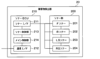
- the obstacle detection unit 20 includes a sonar unit 200, a sonar ECU 210, and the like, as shown in FIG.
- the sonar unit 200 includes a front (hereinafter, F) sonar 201, a rear (hereinafter, R) sonar 202, a left (hereinafter, LS) sonar 203, and a right (hereinafter, RS). ) It has a sonar 204.
- the F sonar 201, the R sonar 202, the LS sonar 203, and the RS sonar 204 transmit the exploration wave toward the outside of the vehicle 10, and include the reflected wave of the exploration wave due to an obstacle, and the distance between the vehicle 10 and the obstacle.
- each of the sonars 201 to 204 corresponds to a detection unit.
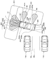
- the detection ranges R1 to R4 are hatched in order to facilitate understanding of the detection ranges R1 to R4 of the sonars 201 to 204. Also, in FIGS. 5A to 5C described later, the detection ranges R1 to R4 are hatched as appropriate to facilitate understanding of the detection ranges R1 to R4 of the sonars 201 to 204.
- the F-sonar 201 has first to fourth F-sonars 201a to 201d, and can detect an obstacle located in front of the vehicle 10, for example, the vehicle body 11 It is mounted on the front bumper 12 in.
- the first F sonar 201a is arranged at the left front corner of the vehicle body 11.
- the second F sonar 201b is arranged at the front right corner of the vehicle body 11.
- the first F sonar 201a and the second F sonar 201b are symmetrically arranged with the vehicle center line L interposed therebetween.
- the 3rd F sonar 201c is arranged between the 1st F sonar 201a and the vehicle center line L.
- the fourth F sonar 201d is disposed between the second F sonar 201b and the vehicle center line L.
- the third F sonar 201c and the fourth F sonar 201d are symmetrically arranged with the vehicle center line L interposed therebetween.
- the R sonar 202 has first to fourth R sonars 202a to 202d, and is mounted on, for example, the rear bumper 13 of the vehicle body 11 so that an obstacle located behind the vehicle 10 can be detected.
- the first R sonar 202a is arranged at the left rear corner of the vehicle body 11.
- the second R sonar 202b is arranged at the right rear corner of the vehicle body 11.
- the first R sonar 202a and the second R sonar 202b are symmetrically arranged with the vehicle center line L interposed therebetween.
- the third R sonar 202c is arranged between the first R sonar 202a and the vehicle center line L.
- the fourth R sonar 202d is arranged between the second R sonar 202b and the vehicle center line L.
- the third R sonar 202c and the fourth R sonar 202d are symmetrically arranged with the vehicle center line L interposed therebetween.
- the first to fourth F sonars 201a to 201d are arranged so that the detection ranges of adjacent sonars overlap.
- the first to fourth F sonars 201a to 201d are integrally connected and are configured to output one detection signal as a whole. That is, in the present embodiment, the first to fourth F sonars 201a to 201d constitute the detection range R1 in front of the vehicle 10 as a whole.
- the F sonar 201 of the present embodiment is in a failed state as a whole.
- the first to fourth R sonars 202a to 202d are arranged such that the detection ranges of adjacent sonars overlap.
- the first to fourth R sonars 202a to 202d are integrally connected and are configured to output one detection signal as a whole. That is, in the present embodiment, the first to fourth R sonars 202a to 202d constitute the detection range R2 behind the vehicle 10 as a whole.
- the R sonar 202 of the present embodiment is in a failed state as a whole.
- the LS sonar 203 has first and second LS sonars 203a and 203b, and is provided on the left side of the vehicle body 11 in the vehicle width direction so that an obstacle on the left side of the vehicle 10 can be detected.
- the first LS sonar 203a is arranged between the left side door mirror 14 and the first F sonar 201a in the front-rear direction of the vehicle body 11.
- the second LS sonar 203b is arranged between the left door panel 15 and the first R sonar 202a in the front-rear direction of the vehicle body 11.
- the RS sonar 204 has first and second RS sonars 204a and 204b, and is provided on the right side of the vehicle body 11 in the vehicle width direction so that an obstacle on the right side of the vehicle 10 can be detected.
- the first RS sonar 204a is disposed between the right side door mirror 16 and the second F sonar 201b in the front-rear direction of the vehicle body 11.
- the first LS sonar 203a and the first RS sonar 204a are arranged symmetrically with the vehicle center line L interposed therebetween.
- the second RS sonar 204b is arranged between the right door panel 17 and the second R sonar 202b in the front-rear direction of the vehicle body 11.
- the second LS sonar 203b and the second RS sonar 204b are arranged symmetrically with the vehicle center line L interposed therebetween.
- the first and second LS sonars 203a and 203b are arranged independently of each other, and are configured to output their respective detection signals. That is, in the present embodiment, the first LS sonar 203a and the second LS sonar 203b respectively configure the detection range R3 on the left side of the vehicle 10. Therefore, in the present embodiment, the first LS sonar 203a and the second LS sonar 203b will not be in a failure state as a whole even if one of the sonars fails.
- first and second RS sonars 204a and 204b are arranged independently of each other and are configured to output respective detection signals. That is, in the present embodiment, each of the first RS sonar 204a and the second RS sonar 204b constitutes the detection range R4 on the right side of the vehicle 10. Therefore, in the present embodiment, the first RS sonar 204a and the second RS sonar 204b will not be in a failure state as a whole even if one of the sonars fails.
- the sonar ECU 210 is configured to include a sonar I/F 211, a communication I/F 212, a sonar control unit 213, a main control unit 214, and the like.
- the sonar I/F 211 is an interface for communicating between each of the sonars 201 to 204 and the sonar control unit 213.
- the communication I/F 212 is an interface for communicating between the main control unit 214 and the vehicle-mounted communication bus 100.
- the ECU is an abbreviation for Electronic Control Unit, and the same applies to the ECU described later.
- the sonar control unit 213 and the main control unit 214 are each configured by a so-called in-vehicle microcomputer including a CPU, a ROM, a RAM, a non-volatile RAM, etc., which are not shown.
- CPU is an abbreviation for Central Processing Unit
- ROM is an abbreviation for Read Only Memory
- RAM is an abbreviation for Random Access Memory.
- the sonar control unit 213 and the main control unit 214 realize various control operations by the CPU reading a program (that is, each routine described below) from the ROM or the non-volatile RAM and executing the program.
- Various data for example, initial values, look-up tables, maps, etc.
- a storage medium such as a ROM is a non-transitional substantive storage medium.
- the sonar control unit 213 is connected to the F sonar 201, the R sonar 202, the LS sonar 203, and the RS sonar 204 via the sonar I/F 211, and is also connected to the main control unit 214. Then, the sonar control unit 213 determines whether or not each of the sonars 201 to 204 has a failure based on the detection signal from each of the sonars 201 to 204. For example, when the detection signal is not input, the sonar control unit 213 determines that the sonar that inputs the detection signal has a failure. Further, when the detection signal exceeding the predetermined threshold is input, the sonar control unit 213 determines that the sonar inputting the detection signal has a failure. Then, the sonar control unit 213 outputs the failure state of each of the sonars 201 to 204 to the main control unit 214 together with the detection signal from each of the sonars 201 to 204.
- the F sonar 201 is configured such that the first to fourth F sonars 201a to 201d are integrally connected. Therefore, when at least one of the first to fourth F sonars 201a to 201d is out of order, the F sonar 201 is determined to be out of order as a whole.
- the R sonar 202 has first to fourth R sonars 202a to 202d, but if at least one of the first to fourth R sonars 202a to 202d is out of order, as a whole. It is determined to be out of order.
- the LS sonar 203 is configured such that the first LS sonar 203a and the second LS sonar 203b are independent of each other. Therefore, even if one of the first LS sonar 203a and the second LS sonar 203b is out of order, the LS sonar 203 is not determined to be out of order as a whole, but is determined to be partially out of order. It Similarly, even if one of the first RS sonar 204a and the second RS sonar 204b is out of order, the RS sonar 204 is not determined to be out of order as a whole, but is determined to be partially out of order. It
- the main control unit 214 has a function of performing a predetermined process based on a detection signal of the sonar unit 200, an image signal of the camera unit 300 described later, and detection signals of various sensors 80 and the like. Specifically, the main control unit 214 has a function of appropriately controlling the steering unit 50, the brake unit 60, the power train unit 70, and the like to execute the assisted traveling of the vehicle 10. Specifically, the vehicle will be described later. It also has a function of executing 10 automatic parking processes. Then, when executing the automatic parking process, the main control unit 214 is based on the detection signal and the failure information input from the sonar control unit 213 and the image signal and the failure information input from the camera control unit 313 described later. To execute automatic parking processing. Further, when executing the automatic parking process, the main control unit 214 executes a process of displaying an image corresponding to the display 41, which will be described later, in the image display unit 40.
- the image acquisition unit 30 includes a camera unit 300, a camera ECU 310, and the like, as shown in FIG.
- the camera unit 300 has an F camera 301, an R camera 302, an LS camera 303, and an RS camera 304.
- the F camera 301, the R camera 302, the LS camera 303, and the RS camera 304 are configured to include an image sensor such as a charge coupled device (that is, CCD).
- the F camera 301, the R camera 302, the LS camera 303, and the RS camera 304 output image signals corresponding to the situation around the vehicle 10.
- each of the cameras 301 to 304 corresponds to the image pickup section.
- the locations of the cameras 301 to 304 will be described below with reference to FIG. In FIG. 1, the detection ranges of the cameras 301 to 304 are shown as R11 to R14.
- the F camera 301 is attached to the front portion of the vehicle body 11 so that the image signal in the detection range R11 in front of the vehicle 10 can be acquired.
- the R camera 302 is attached to a rear side portion of the vehicle body 11 so that an image signal in the detection range R12 behind the vehicle 10 can be acquired.
- the LS camera 303 is attached to, for example, the left side door mirror 14 so that an image signal in the detection range R13 on the left side of the vehicle 10 can be acquired.
- the RS camera 304 is attached to the right side door mirror 16 so as to acquire an image signal in the detection range R14 on the right side of the vehicle 10.
- the camera ECU 310 is configured to include a camera I/F 311, a communication I/F 312, a camera control unit 313, and the like.
- the camera I/F 311 is an interface for communicating between each of the cameras 301 to 304 and the camera control unit 313.
- the communication I/F 312 is an interface for performing communication between the camera control unit 313 and the vehicle-mounted communication bus 100.
- the camera control unit 313 is configured by a so-called in-vehicle microcomputer including a CPU, ROM, RAM, non-volatile RAM, and the like, which are not shown. Then, the camera control unit 313 realizes various control operations by the CPU reading a program (that is, each routine described below) from the ROM or the nonvolatile RAM and executing the program. Various data (for example, initial values, look-up tables, maps, etc.) used when the program is executed are stored in advance in the ROM or the nonvolatile RAM.
- a storage medium such as a ROM is a non-transitional substantive storage medium.
- the camera control unit 313 is connected to the F camera 301, the R camera 302, the LS camera 303, and the RS camera 304 via the camera I/F 311. Then, the camera control unit 313 determines whether or not each of the cameras 301 to 304 has a failure based on the image signal captured by each of the cameras 301 to 304. For example, when the image signal is not input, the camera control unit 313 determines that the camera that inputs the image signal has a failure. Further, when only the image (that is, the pixel) in the specific area has not changed despite the image signal being input, the camera control unit 313 causes a failure in the camera that inputs the image signal. It is determined that Then, the camera control unit 313 outputs the failure state of each of the cameras 301 to 304 to the main control unit 214 together with the image signal.
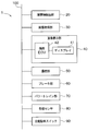
- the image display unit 40 includes a display 41, a drawing ECU 42, and the like.
- the display 41 is arranged, for example, near the center of the instrument panel or in a combination meter provided in front of the driver's seat. Further, the display 41 is configured to be capable of full color display, for example, a liquid crystal display or an organic EL display.
- the display 41 may be, for example, a head-up display or the like, or may be a touch panel that can be operated by an occupant.
- the drawing ECU 42 includes a drawing control unit (not shown) and the like, and draws a peripheral map of the vehicle 10 on the display 41, or draws an image based on an operation of an occupant on the display 41. Further, the drawing ECU 42 draws an image corresponding to the automatic parking process on the display 41 when the automatic parking process is being performed. In this case, the drawing ECU 42 draws an image corresponding to the display 41 when a failure occurs in each of the sonars 201 to 204 and each of the cameras 301 to 304.
- the steering section 50 includes a steering sensor, a steering ECU, and the like, which are not shown. Then, when the assisted traveling of the vehicle 10 is executed, the steering unit 50 controls the traveling direction of the vehicle 10 according to the control signal input from the main control unit 214.
- the brake unit 60 includes a brake sensor, a brake ECU, and the like, which are not shown. Then, when the assisted traveling of the vehicle 10 is executed, the brake unit 60 generates a braking force according to the control signal input from the main control unit 214, and automatically stops the vehicle 10. For example, when a hydraulic brake is provided, the brake unit 60 adjusts the braking force by controlling an actuator provided in the hydraulic circuit of the hydraulic brake. In addition, for example, when a motor is provided as a driving source, the brake unit 60 adjusts the braking force by regenerative braking by controlling the electric power supplied to the motor.
- the power train unit 70 includes a drive source mounted on the vehicle 10, a mechanism for transmitting the drive force of the drive source to the drive wheels, a power train ECU, and the like. Then, when the assisted traveling of the vehicle 10 is executed, the power train unit 70 adjusts the driving force according to the control signal input from the main control unit 214. For example, when the drive source is an internal combustion engine, the power train unit 70 controls the opening degree of the throttle device and the fuel injection amount to adjust the driving force. In addition, for example, when the drive source is a motor, the power train unit 70 adjusts the driving force by controlling the electric power supplied to the motor.
- the various sensors 80 include a vehicle speed sensor, a gyro sensor, a shift position sensor, and the like. Then, the various sensors 80 output detection signals respectively detected by the various sensors 80 to the main control unit 214.
- the automatic parking switch 90 is a switch for the passenger to automatically park the vehicle 10, and is provided, for example, near the center of the instrument panel. Then, when the automatic parking switch 90 is operated, the main control unit 214 executes the automatic parking process of the vehicle 10.
- the automatic parking switch 90 may be displayed on the display 41 when the display 41 is a touch panel.
- the above is the configuration of the parking assistance device 1 in the present embodiment.
- the automatic parking process executed by the main control unit 214 of the parking assistance device 1 of the present embodiment will be described.
- the said vehicle 10 is demonstrated as the own vehicle 10.
- the processing content of the main control unit 214 is the same when the own vehicle 10 is parked in parallel.
- the parallel parking is a parking mode in which the vehicle 10 is parked so that the parked vehicle and the vehicle 10 are arranged along the vehicle width direction of the vehicle 10.
- Parallel parking is a parking mode in which the vehicle 10 is parked so that the parked vehicle and the vehicle 10 are arranged along the front-rear direction of the vehicle 10.
- the automatic parking process is executed when the automatic parking switch 90 is operated as described above. Further, in the following, as shown in FIGS. 5A to 5C, an example will be described in which the parking space PS is on the left side of the vehicle 10, and the parking vehicles 110 are parked on both sides of the parking space PS. ..
- the parking space detection process for detecting the parking space PS is executed as shown in FIG. 5A.
- a process of adjusting the angle of the own vehicle 10 to park the own vehicle 10 in the parking space PS (hereinafter, The angle adjustment process) is executed.
- the parking process for parking the host vehicle 10 in the parking space PS is executed as shown in FIG. 5C.
- the main control unit 214 When executing the automatic parking process, the main control unit 214 outputs various control signals to the steering unit 50, the power train unit 70, the brake unit 60, and the like to control the self-parking process. The traveling direction of the vehicle 10 and the vehicle speed of the host vehicle 10 are controlled.
- the main control unit 214 derives a route to the parking space PS and controls the traveling of the host vehicle 10 along the route.
- the main control unit 214 causes the display 41 to display a corresponding image.
- the main control unit 214 detects the parking space PS on the left side of the vehicle 10 while moving the vehicle 10 forward, as shown in FIG. 5A. In this case, the main control unit 214 recognizes the front state of the vehicle 10 based on the detection signal of the F sonar 201 and the image signal of the F camera 301, and moves the vehicle 10 forward. Further, the main control unit 214 detects the parking space PS by recognizing the state on the left side of the vehicle 10 based on the detection signal of the LS sonar 203 and the image signal of the LS camera 303.
- the main control unit 214 is the first parking space detection process, which is the first parking space detection process. Car parking space detection processing is executed.
- the main control unit 214 cannot recognize the state in front of the vehicle 10, and therefore does not execute the parking space detection process.
- the main control unit 214 cannot recognize the state on the left side of the vehicle 10, and therefore does not execute the parking space detection process.
- the failure of the LS sonar 203 here means a state in which the first LS sonar 203a and the second LS sonar 203b are in failure.
- the main control unit 214 differs from the first parking space detection process. 2 Carry out parking space detection processing. Further, when one of the LS sonar 203 and the LS camera 303 is out of order and at least one of the F sonar 201 and the F camera 301 is normal, the main control unit 214 executes the second parking space detection process. ..
- the main control unit 214 detects the parking space PS using only the detection signal of the LS sonar 203.
- the main control unit 214 recognizes the parked vehicle 110 from the detection signal of the LS sonar 203 and detects the parking space PS. Therefore, the main control unit 214 cannot complete the parking space detection process when the parked vehicle 110 does not exist. Therefore, the main control unit 214 causes the display 41 to display an image notifying that it is difficult to complete the parking space detection process when the parked vehicle 110 is not parked.
- the main control unit 214 detects the parking space PS using only the image signal of the LS camera 303.
- the main control unit 214 recognizes the white line WL from the image signal of the LS camera 303 and detects the parking space PS. Therefore, the main control unit 214 cannot complete the parking space detection process when the white line WL does not exist. Therefore, when the white line WL does not exist, the main control unit 214 causes the display 41 to display an image notifying that it is difficult to complete the parking space detection process.
- the LS sonar 203 has a first LS sonar 203a and a second LS sonar 203b, and the first LS sonar 203a and the second LS sonar 203b are independent of each other. Therefore, when one of the first LS sonar 203a and the second LS sonar 203b is out of order, the main control unit 214 determines that part of the LS sonar 203 is out of order, and executes the second parking space detection process. To do. In this case, when the LS camera 303 is normal, the main control unit 214 executes the second parking space detection process using the normal LS sonar detection signal and the image signal of the LS camera 303.
- the main control unit 214 executes the second parking space detection process using only the detection signal of the normal LS sonar. That is, when the LS camera 303 is out of order, the main control unit 214 executes the parking space detection process that makes it difficult to complete the parking space detection process unless the parked vehicle 110 is parked.
- the F sonar 201 is integrated with the first to fourth F sonars 201a to 201d. Therefore, the main control unit 214 determines that the F sonar 201 as a whole has failed if at least one of the first to fourth F sonars 201a to 201d has failed.
- the second parking space detection process of this embodiment is a process that is more limited than the first parking space detection process, as described above.
- the main control unit 214 adjusts the angle of the host vehicle 10 with respect to the parking space PS in order to park the host vehicle 10 in the detected parking space PS.
- the angle of the host vehicle 10 is adjusted by moving the host vehicle 10 to the front right. Therefore, the main control unit 214 recognizes the state in front of the vehicle 10 based on the detection signal of the F sonar 201 and the image signal of the F camera 301. Further, the main control unit 214 recognizes the right side state of the vehicle 10 based on the detection signal of the RS sonar 204 and the image signal of the RS camera 304. Then, the main control unit 214 executes the angle adjustment processing based on these recognitions.
- the main control unit 214 when the F sonar 201, the F camera 301, the RS sonar 204, and the RS camera 304 are normal, the first angle that is a normal angle adjustment process. Perform adjustment processing.
- the main control unit 214 cannot recognize the state in front of the vehicle 10, and therefore does not execute the angle adjustment processing.
- the main control unit 214 cannot recognize the state on the right side of the vehicle 10, and therefore does not execute the angle adjustment process.
- the failure of the RS sonar 204 here means a state in which the first RS sonar 204a and the second RS sonar 204b have a failure.
- the main control unit 214 differs from the first angle adjustment process in the second angle adjustment process. Executes angle adjustment processing.
- the main control unit 214 executes the second angle adjustment processing. ..
- the main control unit 214 has failed in at least one of the F sonar 201, the F camera 301, the RS sonar 204, and the RS camera 304. Also, the second angle adjustment processing is executed. Then, when the second angle adjustment processing is being performed, the main control unit 214 causes the display 41 to display an image indicating that the second angle adjustment processing is being performed.
- the RS sonar 204 has a first RS sonar 204a and a second RS sonar 204b, and the first RS sonar 204a and the second RS sonar 204b are independent of each other. Therefore, when one of the first RS sonar 204a and the second RS sonar 204b is out of order, the main control unit 214 determines that part of the RS sonar 204 is out of order, and executes the second angle adjustment processing. .. In this case, when the RS camera 304 is normal, the main control unit 214 executes the second angle adjustment process using the normal detection signal of the RS sonar and the image signal of the RS camera 304.
- the main control unit 214 executes the second angle adjustment processing using only the detection signal of the normal RS sonar. It should be noted that the second angle adjustment process of the present embodiment is a process that is more limited than the first angle adjustment process as described above.
- the main control unit 214 parks the vehicle 10 in the parking space PS, as shown in FIG. 5C.
- the vehicle 10 is parked in the parking space PS by moving the vehicle 10 to the left rear. Therefore, the main control unit 214 recognizes the state behind the vehicle 10 based on the detection signal of the R sonar 202 and the image signal of the R camera 302. Further, the main control unit 214 recognizes the right side state of the vehicle 10 based on the detection signal of the RS sonar 204 and the image signal of the RS camera 304. Then, the main control unit 214 parks the vehicle 10 in the parking space PS based on these recognitions.
- the main control unit 214 when the R sonar 202, the R camera 302, the RS sonar 204, and the RS camera 304 are normal, the first parking process which is a normal parking process. To execute.
- the main control unit 214 cannot recognize the state behind the vehicle 10, and therefore does not execute the parking process.
- the main control unit 214 cannot recognize the state on the right side of the vehicle 10, and therefore does not execute the parking process.
- the failure of the RS sonar 204 here means a state in which the first RS sonar 204a and the second RS sonar 204b have a failure.
- the main control unit 214 performs the second parking different from the first parking process. Execute the process.
- the main control unit 214 executes the second parking process. That is, if the main controller 214 can recognize the rear and right sides of the vehicle 10, at least one of the R sonar 202, the R camera 302, the RS sonar 204, and the RS camera 304 has a failure. Also, the second parking process is executed. Then, when the second parking process is being performed, the main control unit 214 causes the display 41 to display an image indicating that the second parking process is being performed.
- the main control unit 214 determines that a part of the RS sonar 204 is in failure, and the second parking is performed. Execute the process. In this case, when the RS camera 304 is normal, the main control unit 214 executes the second parking process using the normal detection signal of the RS sonar and the image signal of the RS camera 304. In addition, when the RS camera 304 is out of order, the main control unit 214 executes the second parking process using only the detection signal of the normal RS sonar.
- the R sonar 202 is integrated with the first to fourth R sonars 202a to 202d. Therefore, the main control unit 214 determines that the R sonar 202 as a whole has failed if at least one of the first to fourth R sonars 202a to 202a has failed.
- the second parking process of the present embodiment is a process that is more limited than the first parking process, as described above.
- the main control unit 214 automatically stops the vehicle 10 in an emergency when an obstacle is detected during the automatic parking process (i.e., automatic brake control). Also run. That is, the main control unit 214 is configured to be able to execute emergency braking. For example, when the main control unit 214 detects an obstacle during the execution of the angle adjustment process and determines that the vehicle 10 may come into contact with the obstacle, the main control unit 214 executes the emergency brake control. Then, the main control unit 214 notifies the display 41 that the vehicle 10 has been stopped by executing the emergency brake control. In this case, in the present embodiment, the main control unit 214 restarts the stopped processing when the occupant operates the automatic parking switch 90 again after executing the emergency brake control.
- the main control unit 214 restarts the stopped processing when the occupant operates the automatic parking switch 90 again after executing the emergency brake control.
- the main control unit 214 executes the following processing when the automatic parking switch 90 is operated as described above.
- the main control unit 214 executes the automatic parking process by outputting and controlling various control signals to the steering unit 50, the power train unit 70, the brake unit 60, etc. as described above.
- the main control unit 214 executes the emergency brake control to stop the automatic parking process. In this case, for example, when the automatic parking switch 90 is operated again, the main control unit 214 restarts the stopped processing.
- the operation of the occupant on the power train unit 70 for example, accelerator pedal operation
- the operation on the brake unit 60 for example, brake pedal operation). Is valid.
- step S101 the main control unit 214 grasps the detection signals detected by the sonars 201 to 204 and the failure information of the sonars 201 to 204.
- the failure information of the sonars 201 to 204 is input from the sonar control section 213 by the failure determination of the sonars 201 to 204 performed by the sonar control section 213 as described above.
- step S102 the main control unit 214 grasps the image signals captured by the cameras 301 to 304 and the failure information of the cameras 301 to 304.
- the failure information of each of the cameras 301 to 304 is input from the camera controller 313 by the failure determination of each of the cameras 301 to 304 performed by the camera controller 313 as described above.
- the main control unit 214 grasps the state of the automatic parking process in step S103. That is, the main control unit 214 grasps which of the parking space detection process, the angle adjustment process, and the parking process should be executed. It should be noted that this determination is realized, for example, by appropriately storing the processing content in the RAM or the like when performing each processing, and reading the stored information. The determination here is made in the same manner not only when each process is being processed but also when each process is started. For example, when the main control unit 214 determines that the parking space detection process is being performed, it includes the case where the parking space detection process is started and the case where the parking space detection process is started.
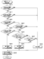
- the main control unit 214 determines in step S104 whether or not the parking space detection process is being performed. Then, when determining that the parking space detection process is being performed (that is, step S104: YES), the main control unit 214 executes the parking space detection process in step S105. On the other hand, when determining that the parking space detection process is not being performed (that is, step S104: NO), the main control unit 214 determines whether the angle adjustment process is being performed at step S106.
- step S106 determines that the angle adjustment process is being performed (that is, step S106: YES)
- step S106: NO the main control unit 214 executes the parking processing in step S108.
- the parking space detection process of step S105 the angle adjustment process of step S107, and the parking process of step S108 will be described in order with reference to FIGS. 8 to 10.
- the F-side detection device in FIGS. 8 and 9 is a collective representation of the F sonar 201 and the F camera 301.
- the detection device on the R side in FIG. 10 is a collective representation of the R sonar 202 and the R camera 302.
- the detection device on the LS side in FIG. 8 is a collective representation of the LS sonar 203 and the LS camera 303.
- the RS-side detection device in FIGS. 9 and 10 is a collective representation of the RS sonar 204 and the RS camera 304.
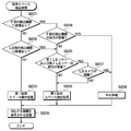
- the parking space detection process will be described with reference to FIG.
- the parking space PS is detected using the information of the F sonar 201, the LS sonar 203, the F camera 301, and the LS camera 303.
- step S201 the main control unit 214 determines whether or not the F-side detection device has a failure. That is, it is determined whether or not a failure has occurred in at least one of the F sonar 201 and the F camera 301.
- the main control unit 214 determines that no failure has occurred in the F-side detection device (that is, step S201: NO)
- a failure has occurred in the LS-side detection device in step S202. It is determined whether or not there is. That is, the main control unit 214 determines whether or not at least one of the LS sonar 203 and the LS camera 303 is out of order.
- step S202 determines that no failure has occurred in the detection device on the LS side (that is, step S202: NO)
- the main control part 214 executes the first parking space detection process in step S203. That is, the main control unit 214 executes the first parking space detection process when the F sonar 201, the LS sonar 203, the F camera 301, and the LS camera 303 are all normal.
- the main control unit 214 determines that the LS sonar 203 in step S202 is not a failure when both the first LS sonar 203a and the second LS sonar 203b are normal. That is, in the determination on the LS sonar 203 in step S202, the main control unit 214 determines that the LS sonar 203 has failed if one of the first LS sonar 203a and the second LS sonar 203b has failed.
- step S204 When the main control unit 214 determines in step S201 that a failure has occurred in the F-side detection device (that is, step S201: YES), in step S204 both F-side detection devices fail. Is determined. That is, the main control unit 214 determines in step S204 whether or not both the F sonar 201 and the F camera 301 are out of order. Then, when the main control unit 214 determines that both of the F-side detection devices are not in failure (that is, step S204: NO), both of the first LS sonar 203a and the second LS sonar 203b are determined in step S205. To determine whether or not there is a failure.
- the main control unit 214 determines that both the first LS sonar 203a and the second LS sonar 203b have not failed (that is, S205: NO), it executes the second parking space detection process in step S206. That is, the main control unit 214 executes the second parking space detection process if at least one of the first LS sonar 203a and the second LS sonar 203b is normal in step S206.
- the main control unit 214 determines whether or not the LS camera 303 is out of order in step S207. To do. When determining in step S207 that the LS camera 303 has not failed (that is, step S207: NO), the main control unit 214 executes the second parking space detection process in step S206. In addition, when the main control unit 214 determines in step S202 that a failure has occurred in the detection device on the LS side (that is, S202: YES), the main control part 214 executes the processing from step S205.
- the failure state of the F sonar 201, the LS sonar 203, the F camera 301, and the LS camera 303 is specified, and the process based on the failure state is executed. That is, the process of step S206 is executed when at least one of the F sonar 201, the LS sonar 203, the F camera 301, and the LS camera 303 has a failure, and the states of the front and left sides of the vehicle 10 can be recognized. Is. Therefore, the main control unit 214 executes the parking space detection process using the information of the detection device that is not in failure.
- the white line WL is If it does not exist, the parking space PS cannot be detected.
- the LS camera 303 is out of order and the first and second LS sonars 203a and 203b are normal, the parking space PS cannot be detected unless the parked vehicle 110 is parked.
- the second parking space detection process using the normal one sonar and the LS camera 303 is performed.
- the main control unit 214 When the main control unit 214 detects the parking space PS by executing the first parking space detection process or the second parking space detection process as described above, the main control unit 214 derives the route to the parking space PS. .. After that, the main control unit 214 causes the vehicle 10 to travel along the derived route in the angle adjustment process and the parking process described later.
- step S204 determines in step S204 that both of the F-side detection devices are out of order (that is, step S204: YES), it cannot recognize the state in front of the host vehicle 10. ..
- step S207 determines in step S207 that the LS camera 303 is out of order (that is, step S207: YES)
- step S207 determines in step S207 that the LS camera 303 is out of order (that is, step S207: YES)
- step S207 determines in step S207 that the LS camera 303 is out of order
- the main control unit 214 causes the processing of displaying the image of the processing corresponding to the display 41 in step S209. For example, when performing the first parking space detection process in step S203, the main control unit 214 causes the display 41 to display an image notifying that the parking space detection process is normally performed.
- the main control unit 214 notifies an image of the detection device in failure and an image notifying that the second parking space detection process is executed. Display on the display 41. In this case, if the LS sonar 203 is out of order and the white line WL does not exist, it is also notified that the parking space detection processing is not completed. Further, if the LS camera 303 is out of order and the parked vehicle 110 is not parked, the fact that the parking space detection processing is not completed is also notified. Further, when one of the first LS sonar 203a and the second LS sonar 203b is out of order, the display 41 displays an image notifying the detection device that is out of order.
- the main control unit 214 displays an image on the display 41 notifying the malfunctioning detection device and notifying that the parking space detection process cannot be executed. To be done. Thereby, the occupant can recognize the state of the parking space detection processing.
- step S203 is included in the failure handling processing corresponding to the failed device, because the first parking space detection process is executed even if the R sonar 202 or the like has failed.
- the angle adjustment processing will be described with reference to FIG.
- the angle of the vehicle 10 with respect to the parking space PS is adjusted using the information of the F sonar 201, the RS sonar 204, the F camera 301, and the RS camera 304.
- step S301 the main control unit 214 determines whether or not a failure has occurred in the F-side detection device, as in step S201.
- the main control unit 214 determines that no failure has occurred in the F-side detection device (that is, step S301: NO)
- step S302 determines that no failure has occurred in the detection device on the RS side (that is, step S302: NO)
- the main control unit 214 executes the first angle adjustment process in step S303. That is, the main control unit 214 executes the angle adjustment processing based on the detection signals of the F sonar 201 and the RS sonar 204 and the image signals of the F camera 301 and the RS camera 304.
- the main control unit 214 determines that the RS sonar 204 in step S302 is not a failure when both the first RS sonar 204a and the second RS sonar 204b are normal. That is, in the determination on the RS sonar 204 in step S302, the main control unit 214 determines that the RS sonar 204 is out of order if one of the first RS sonar 204a and the second RS sonar 204b is out of order.
- step S304 similarly to step S204, F-side detection is performed. Determine if both devices are faulty.
- step S304 similarly to step S204, F-side detection is performed. Determine if both devices are faulty.
- step S304: NO both of the first RS sonar 204a and the second RS sonar 204b are determined in step S305. It is determined whether or not there is a failure.
- the main control unit 214 determines that both the first RS sonar 204a and the second RS sonar 204b have not failed (that is, S305: NO), it executes the second angle adjustment processing in step S306. That is, the main control unit 214 executes the second angle adjustment processing if at least one of the first RS sonar 204a and the second RS sonar 204b is normal in step S306.
- step S307 determines in step S307 whether or not the RS camera 304 is out of order. To do.
- step S307 that the RS camera 304 has not failed (that is, step S307: NO)
- the main controller 214 executes the second angle adjustment processing in step S306.
- the main control unit 214 determines in step S302 that a failure has occurred in the RS-side detection device (that is, S302: YES)
- the main control part 214 executes the processes of step S305 and subsequent steps.
- step S306 the failure state of the F sonar 201, RS sonar 204, F camera 301, RS camera 304 is specified, and processing based on the failure state is executed. That is, the process of step S306 is executed when at least one of the F sonar 201, the RS sonar 204, the F camera 301, and the RS camera 304 has a failure, and the states of the front and right sides of the vehicle 10 can be recognized. Is. For this reason, the main control unit 214 executes the angle adjustment process using the information of the detection device that has not failed.
- step S304 determines in step S304 that both of the F-side detection devices have failed (that is, step S304: YES), it cannot recognize the state in front of the host vehicle 10.
- step S307 determines that the RS camera 304 is out of order in step S307 (that is, step S307: YES)
- step S307 determines that the RS camera 304 is out of order in step S307
- step S307 determines that the RS camera 304 is out of order in step S307
- the main control unit 214 causes the process of displaying the image of the process corresponding to the display 41 in step S309. For example, when the first angle adjustment process is performed in step S303, the main control unit 214 causes the display 41 to display an image notifying that the angle adjustment process is normally performed.
- the main control unit 214 when executing the second angle adjustment processing in step S306, notifies the failure detection device and displays an image notifying that the second angle adjustment processing is executed on the display 41. To be displayed in.
- the main control unit 214 when stopping the angle adjustment process in step S308, notifies the failure detection device and displays an image notifying that the angle adjustment process cannot be performed on the display 41. To do so.
- step S303 is included in the failure handling processing corresponding to the failed device because the first angle adjustment processing is executed even if the R sonar 202 or the like has failed.
- the parking process will be described with reference to FIG.
- the vehicle 10 is parked in the parking space PS using the information of the R sonar 202, the RS sonar 204, the R camera 302, and the RS camera 304.
- step S401 the main control unit 214 first determines whether or not a failure has occurred in the detection device on the R side. That is, it is determined whether or not at least one of the R sonar 202 and the R camera 302 is out of order.
- the main control unit 214 determines that no failure has occurred in the R-side detection device (that is, step S401: NO)
- step S402 the RS-side detection is performed as in step S302. Determine if the device is defective.
- the main control unit 214 executes the first parking process in step S403. That is, the main control unit 214 executes the parking process based on the detection signals of the R sonar 202 and the RS sonar 204 and the image signals of the R camera 302 and the RS camera 304.
- the main control unit 214 determines that there is no failure when both the first RS sonar 204a and the second RS sonar 204b are normal, as in step S302.
- step S404 When the main control unit 214 determines in step S401 that a failure has occurred in the R-side detection device (that is, step S401: YES), in step S404 both R-side detection devices fail. Is determined. When the main control unit 214 determines that both the R-side detection devices are not in failure (that is, step S404: NO), both the first RS sonar 204a and the second RS sonar 204b are determined in step S405. It is determined whether or not there is a failure.
- step S405 NO
- the main controller 214 executes the second parking process in step S406. That is, the main control unit 214 executes the second parking process if at least one of the first RS sonar 204a and the second RS sonar 204b is normal in step S406.
- step S407 determines in step S407 whether or not the RS camera 304 is out of order. To do.
- step S407 determines in step S407 that the RS camera 304 has not failed (that is, step S407: NO)
- the main control unit 214 executes the second parking process in step S406.
- the main control unit 214 determines in step S402 that a failure has occurred in the RS-side detection device (that is, S402: YES)
- the main control unit 214 executes the processing from step S405.
- the failure state of the R sonar 202, the RS sonar 204, the R camera 302, and the RS camera 304 is specified, and the processing based on the failure state is executed. That is, the processing of step S406 is executed when at least one of the R sonar 202, the RS sonar 204, the R camera 302, and the RS camera 304 has a failure, and the rear and right sides of the vehicle 10 can be recognized. Is. Therefore, the main control unit 214 executes the parking space detection process using the information of the detection device that is not in failure.
- step S404 determines in step S404 that both of the R-side detection devices have failed (that is, step S404: YES), it cannot recognize the state behind the vehicle 10.
- step S407 determines in step S407 that the RS camera 304 is out of order (that is, step S407: YES)
- step S407 stops the parking process in step S408.
- the main control unit 214 executes the process of displaying the image of the process corresponding to the display 41 in step S409. For example, when performing the first parking process in step S403, the main control unit 214 causes the display 41 to display an image notifying that the parking process is normally performed.
- the main control unit 214 displays an image on the display 41 notifying the faulty detection device and also executing the second parking process. To be done.
- the main control unit 214 when stopping the parking process in step S408, notifies the detection device that is out of order and displays an image notifying that the parking process cannot be executed on the display 41. To do.
- step S403 is included in the failure handling processing corresponding to the failed device, because the first parking process is executed even if the F sonar 201 or the like has failed.
- step S109 the main control unit 214 determines whether or not the cancellation processing has been executed or the automatic parking processing has ended.
- the main control unit 214 determines that the processing has not been stopped and the automatic parking processing has not ended (that is, step S109: NO)
- the processing from step S101 onward is repeated.
- the main control unit 214 determines that the process is stopped or the automatic parking process is completed (that is, step S109: YES)
- the main control unit 214 ends the automatic parking process.
- the process based on the failure state of the sonars 201 to 204 and the cameras 301 to 304 used in each process is performed. That is, in the example of FIG. 5A that executes the parking space detection process, the main control unit 214 detects the parking space based on the failure states of the F sonar 201 and the F camera 301 and the failure states of the LS sonar 203 and the LS camera 303. Execute the process. Further, in the example of FIG. 5B that executes the angle adjustment processing, the main control unit 214 performs the angle adjustment processing based on the failure states of the F sonar 201 and F camera 301 and the failure states of the RS sonar 204 and RS camera 304.
- the main control unit 214 executes the parking space detection process based on the failure states of the R sonar 202 and the R camera 302 and the failure states of the RS sonar 204 and the RS camera 304. ..
- the main control unit 214 executes each of the second processing or the cancellation processing when the detection device that acquires the information necessary for each processing is out of order. In other words, the main control unit 214 continues each process as it is, even if the detection device that acquires information that is not necessary in each process is out of order. Therefore, for example, even if the F-sonar 201 fails during the parking process, the parking process is executed as it is. Therefore, the occupant can effectively use the automatic parking process.
- the main control unit 214 may continue each process even if a part of the detection device that acquires information necessary for each process is out of order.
- the second parking space detection process is executed if at least one of the LS sonar 203 and the LS camera 303 is normal even if one of the F sonar 201 and the F camera 301 is out of order. .. Therefore, the occupant can effectively utilize the automatic parking process.
- the first LS sonar 203a and the second LS sonar 203b are independent of each other. Then, even if one sonar of the first LS sonar 203a and the second LS sonar 203b is out of order, the main control unit 214 executes each second process using the detection signal from the other sonar.
- the first RS sonar 204a and the second RS sonar 204b are independent of each other. Then, even if one of the first RS sonar 204a and the second RS sonar 204b is out of order, the main controller 214 executes each second process using the detection signal from the other sonar. Therefore, the occupant can effectively use the automatic parking process.
- the second embodiment will be described.
- the present embodiment differs from the first embodiment in that parking space detection processing and angle adjustment processing are changed. Since the other points are the same as those in the first embodiment, description thereof will be omitted here.
- step S210 the main control unit 214 determines whether or not both the R-side detection devices used in the parking process are out of order. That is, the main control unit 214 determines whether or not both the R sonar 202 and the R camera 302 are out of order. Then, when the main control unit 214 determines in step S210 that neither of the R-side detection devices has failed (that is, step S210: NO), the main control part 214 executes step S211. In step S211, the main control unit 214 determines whether or not both of the RS-side detection devices used in the parking process and the angle adjustment process have a failure.
- the main control unit 214 determines whether or not both the RS sonar 204 and the RS camera 304 are out of order. When the main control unit 214 determines that both the detection devices on the RS side are not in failure (S211: NO), the main control unit 214 sequentially executes the processes from step S201.
- both of the detection devices on the RS side in step S210 are defective when the RS sonar 204 and the RS camera 304 are defective and the main control unit 214 cannot recognize the state on the right side. is there. That is, here, the failure of the RS sonar 204 is a case where both the first RS sonar 204a and the second RS sonar 204b have a failure.
- step S210 When the main control unit 214 determines in step S210 that both of the R-side detection devices are out of order (that is, step S210: YES), the main control part 214 stops the parking space detection process in step S208. In addition, when the main control unit 214 determines in step S211 that both of the RS-side detection devices are out of order (that is, step S211: YES), the main control part 214 stops the parking space detection process in step S208. To do.
- step S109 Allow the parking process to end.
- step S310 the main control unit 214 determines whether or not both the R-side detection devices used in the parking processing have a failure, as in step S210.
- step S310: NO the main control part 214 sequentially executes the processing from step S301.
- step S310 determines in step S310 that a failure has occurred in the R-side detection device (that is, step S310: YES), it cancels the angle adjustment processing in step S308. ..
- step S109 in the angle adjustment processing, similarly to the parking space detection processing, when the cancellation processing is executed in the subsequent parking processing, the angle adjustment processing is ended, and the automatic parking processing is ended in step S109. To be done.
- the automatic parking process when the automatic parking process is performed, if the detection device used in the subsequent process is out of order, the automatic parking process is stopped before the subsequent process is executed. To do. For this reason, it becomes difficult for the automatic parking process to end halfway, and it is possible to prevent the passenger from being bothered and uncomfortable.
- the obstacle detection unit 20 may be configured to have a distance measuring sensor or the like that detects an obstacle using light instead of each of the sonars 201 to 204.
- the image acquisition unit 30 may be configured to have an image recognition sensor or the like instead of the cameras 301 to 304.
- the main control unit 214 may be integrated with the sonar control unit 213.
- the main control unit 214 may be provided in the camera ECU 310 instead of the sonar ECU 210. Further, as shown in FIG. 13, the main control unit 214 may be provided separately from the sonar ECU 210 and the camera ECU 310, and may be provided in the integrated ECU 120 that executes the overall control of the traveling of the vehicle 10.
- the main controller 214 may determine whether each of the sonars 201 to 204 and each of the cameras 301 to 304 has a failure.
- the angle adjustment process may not be executed in the automatic parking process depending on the position of the vehicle 10 when the parking space PS is detected. That is, if the parking process can be directly executed after the parking space detection process is executed, the angle adjustment process may not be executed.
- the parking space detection process may be executed based on the information of a predetermined period before the parking space detection process is started. Then, when the parking space PS can be detected based on the information before the processing is started, the main control unit 214 may directly perform the angle adjustment processing.
- the F sonar 201 may not be integrated with the first to fourth F sonars 201a to 201d and may be independent from each other. In this case, even in the F sonar 201, a state of partial failure may occur.
- the first to fourth R sonars 202a to 202d are not integrated and may be independent from each other.
- the LS sonar 203 may be integrated with the first LS sonar 203a and the second LS sonar 203b. In this case, if one of the first LS sonar 203a and the second LS sonar 203b is out of order, the LS sonar 203 is determined to be out of order as a whole.
- the first RS sonar 204a and the second RS sonar 204b may be integrated.
- the number of sonars forming the F sonar 201 and the R sonar 202 is not limited to four, and can be changed as appropriate.
- the number of sonars forming the LS sonar 203 and the RS sonar 204 is not limited to two and can be changed as appropriate.
- the specific processing content when performing each second processing can be changed as appropriate, and can be changed or selected by the occupant according to the vehicle type in which the parking assistance device 1 is mounted. You can
- the main control unit 214 may determine not to execute the next parking space detection process after performing the parking space detection process. Good.
- the second angle adjustment process is executed in step S306, it may be determined that the next angle adjustment process after the angle adjustment process is not executed.
- the second parking process is executed in step S406, it may be determined that the next parking process after the parking process is not executed.
- the next automatic parking process may not be executed as a whole. That is, for example, if the next parking process is not executed in the parking process, the next parking space detection process and the angle adjustment process may not be executed.
- the main control unit 214 may be configured such that the emergency brake control is disabled when executing each second process. For example, when one of the F sonar 201 and the F camera 301 is out of order when the second parking space detection process is executed, the vehicle 10 is compared with the case where the F sonar 201 and the F camera 301 are normal. The accuracy of recognizing the state in front of is reduced. Therefore, in such a case, the state in front of the vehicle 10 may be mistakenly recognized. In this case, the occupant may feel annoyed because the emergency brake frequently operates in a falsely recognized state. Therefore, when executing each second process, the main control unit 214 may not execute the emergency brake control. However, when the emergency braking control is not executed, the main control unit 214 preferably performs a process of improving the occupant's attention such as notifying the display 41 that the emergency braking control is not executed.
- each first process may be performed even if one of them is out of order.
- the parking space detection process if the F sonar 201 has higher accuracy than the F camera 301, and the LS sonar 203 and the LS camera 303 are normal, the following may be performed. That is, if the F sonar 201 is normal, the main control unit 214 performs the first parking space detection process even if the F camera 301 is broken, and if the F sonar 201 is broken and the F camera 301 is normal. You may make it perform a 2nd parking space detection process.
- the main control unit 214 may be able to detect the parking space PS with the parking vehicle 110 as a reference if the parking position of the one parking vehicle 110 can be specified. That is, the main control unit 214 determines that the parking space PS exists if the obstacle is not detected from the parked vehicle 110 in a specified width exceeding the vehicle width of the own vehicle 10 on the basis of the identified parked vehicle 110. You may do it.
- control unit and the method described in the present disclosure are realized by a dedicated computer provided by configuring a processor and a memory programmed to execute one or a plurality of functions embodied by a computer program. May be done.
- control unit and the method described in the present disclosure may be realized by a dedicated computer provided by configuring a processor with one or more dedicated hardware logic circuits.
- control unit and the method thereof described in the present disclosure are based on a combination of a processor and a memory programmed to execute one or a plurality of functions and a processor configured by one or more hardware logic circuits. It may be realized by one or more configured dedicated computers.
- the computer program may be stored in a computer-readable non-transition tangible recording medium as an instruction executed by a computer.
Landscapes
- Engineering & Computer Science (AREA)
- Mechanical Engineering (AREA)
- Automation & Control Theory (AREA)
- Transportation (AREA)
- Human Computer Interaction (AREA)
- Chemical & Material Sciences (AREA)
- Combustion & Propulsion (AREA)
- General Physics & Mathematics (AREA)
- Physics & Mathematics (AREA)
- Multimedia (AREA)
- Theoretical Computer Science (AREA)
- Traffic Control Systems (AREA)
- Control Of Driving Devices And Active Controlling Of Vehicle (AREA)
Abstract
La présente invention comprend : une unité de détection d'obstacle (20) pour acquérir un signal de détection qui est basé sur la distance entre un véhicule et un obstacle dans la périphérie du véhicule ; une unité d'acquisition d'image (30) pour acquérir un signal d'image par rapport à la périphérie du véhicule ; et une unité de commande pour exécuter un processus de stationnement automatique dans lequel, sur la base du signal de détection et du signal d'image, un espace de stationnement est détecté et le véhicule est stationné dans l'espace de stationnement. Si l'unité de détection d'obstacle (20) et/ou l'unité d'acquisition d'image (30) fonctionnent mal lors de l'exécution du processus de stationnement automatique, l'unité de commande exécute un processus de réponse à un dysfonctionnement qui est basé sur l'état du processus de stationnement automatique.
Priority Applications (3)
| Application Number | Priority Date | Filing Date | Title |
|---|---|---|---|
| DE112019006043.0T DE112019006043T5 (de) | 2018-12-04 | 2019-11-14 | Parkassistenzvorrichtung |
| CN201980080740.1A CN113165643B (zh) | 2018-12-04 | 2019-11-14 | 停车辅助装置 |
| US17/337,258 US20210284140A1 (en) | 2018-12-04 | 2021-06-02 | Parking assist apparatus |
Applications Claiming Priority (2)
| Application Number | Priority Date | Filing Date | Title |
|---|---|---|---|
| JP2018227570A JP7221669B2 (ja) | 2018-12-04 | 2018-12-04 | 駐車支援装置 |
| JP2018-227570 | 2018-12-04 |
Related Child Applications (1)
| Application Number | Title | Priority Date | Filing Date |
|---|---|---|---|
| US17/337,258 Continuation US20210284140A1 (en) | 2018-12-04 | 2021-06-02 | Parking assist apparatus |
Publications (1)
| Publication Number | Publication Date |
|---|---|
| WO2020116119A1 true WO2020116119A1 (fr) | 2020-06-11 |
Family
ID=70973985
Family Applications (1)
| Application Number | Title | Priority Date | Filing Date |
|---|---|---|---|
| PCT/JP2019/044717 WO2020116119A1 (fr) | 2018-12-04 | 2019-11-14 | Dispositif d'aide au stationnement |
Country Status (5)
| Country | Link |
|---|---|
| US (1) | US20210284140A1 (fr) |
| JP (2) | JP7221669B2 (fr) |
| CN (1) | CN113165643B (fr) |
| DE (1) | DE112019006043T5 (fr) |
| WO (1) | WO2020116119A1 (fr) |
Families Citing this family (4)
| Publication number | Priority date | Publication date | Assignee | Title |
|---|---|---|---|---|
| JP7198391B2 (ja) * | 2020-12-28 | 2022-12-28 | 本田技研工業株式会社 | 車両制御装置、車両制御システム、車両制御方法、およびプログラム |
| JP7213279B2 (ja) * | 2021-02-03 | 2023-01-26 | 本田技研工業株式会社 | 運転支援装置 |
| CN117355456A (zh) * | 2021-05-28 | 2024-01-05 | 日产自动车株式会社 | 转舵控制方法及转舵控制装置 |
| CN113682319B (zh) * | 2021-08-05 | 2023-08-01 | 地平线(上海)人工智能技术有限公司 | 摄像头调整方法及装置、电子设备和存储介质 |
Citations (6)
| Publication number | Priority date | Publication date | Assignee | Title |
|---|---|---|---|---|
| JPS64249B2 (fr) * | 1984-10-12 | 1989-01-05 | Honda Motor Co Ltd | |
| JP2009262701A (ja) * | 2008-04-23 | 2009-11-12 | Fuji Heavy Ind Ltd | 自動制動制御装置 |
| US20170169627A1 (en) * | 2015-12-09 | 2017-06-15 | Hyundai Motor Company | Apparatus and method for failure diagnosis and calibration of sensors for advanced driver assistance systems |
| JP2017165296A (ja) * | 2016-03-17 | 2017-09-21 | 株式会社日立製作所 | 自動運転制御システム |
| US20180196133A1 (en) * | 2016-07-29 | 2018-07-12 | Faraday&Future Inc. | Method and apparatus for detection and ranging fault detection and recovery |
| WO2019181265A1 (fr) * | 2018-03-23 | 2019-09-26 | 日立オートモティブシステムズ株式会社 | Dispositif d'aide au stationnement |
Family Cites Families (18)
| Publication number | Priority date | Publication date | Assignee | Title |
|---|---|---|---|---|
| JP5278031B2 (ja) | 2009-02-24 | 2013-09-04 | 日産自動車株式会社 | 駐車支援装置及び駐車支援方法 |
| JP2010264945A (ja) * | 2009-05-18 | 2010-11-25 | Panasonic Corp | 駐車支援装置、駐車支援方法及び駐車支援プログラム |
| DE102010023162A1 (de) * | 2010-06-09 | 2011-12-15 | Valeo Schalter Und Sensoren Gmbh | Verfahren zum Unterstützen eines Fahrers eines Kraftfahrzeugs beim Einparken in eine Parklücke, Fahrerassistenzeinrichtung und Kraftfahrzeug |
| DE102011082826A1 (de) * | 2011-09-16 | 2013-03-21 | Robert Bosch Gmbh | Verfahren zum Unterstützen eines automatischen Einparkvorgangs eines Einparkhilfesystems eines Fahrzeugs sowie ein entsprechendes Fahrzeug |
| KR20130118116A (ko) * | 2012-04-19 | 2013-10-29 | 현대모비스 주식회사 | 자동 주차 보조 시스템에서 장애물 충돌 회피 장치 및 방법 |
| EP2933152A1 (fr) * | 2012-12-13 | 2015-10-21 | Toyota Jidosha Kabushiki Kaisha | Dispositif d'aide au stationnement |
| KR101514451B1 (ko) * | 2013-01-31 | 2015-04-24 | 주식회사 에이피엑스 | 카메라 통합형 주차 조향 보조 시스템 및 자동 주차 방법 |
| US20150166059A1 (en) * | 2013-12-18 | 2015-06-18 | Automotive Research & Testing Center | Autonomous vehicle driving support system and autonomous driving method performed by the same |
| JP6260462B2 (ja) * | 2014-06-10 | 2018-01-17 | 株式会社デンソー | 運転支援装置 |
| JP6049811B1 (ja) * | 2015-06-23 | 2016-12-21 | 三菱電機株式会社 | 自動駐車制御装置 |
| KR20170058598A (ko) * | 2015-11-19 | 2017-05-29 | 주식회사 만도 | 주차 지원 장치 및 그의 주차 제어 방법 |
| JP6964271B2 (ja) | 2016-03-31 | 2021-11-10 | パナソニックIpマネジメント株式会社 | 運転支援方法およびそれを利用した運転支援装置、自動運転制御装置、車両、プログラム |
| JP6673181B2 (ja) * | 2016-12-19 | 2020-03-25 | 株式会社Soken | 駐車支援装置およびその制御部 |
| KR101915166B1 (ko) * | 2016-12-30 | 2018-11-06 | 현대자동차주식회사 | 자동 주차 시스템 및 자동 주차 방법 |
| DE112017007687T5 (de) | 2017-07-26 | 2020-03-05 | Mitsubishi Electric Corporation | Fahrsteuerungssystem und fahrassistenzverfahren |
| JP6664371B2 (ja) * | 2017-12-13 | 2020-03-13 | 本田技研工業株式会社 | 物体認識装置、物体認識方法及び車両 |
| US10553044B2 (en) * | 2018-01-31 | 2020-02-04 | Mentor Graphics Development (Deutschland) Gmbh | Self-diagnosis of faults with a secondary system in an autonomous driving system |
| JP7199937B2 (ja) * | 2018-11-28 | 2023-01-06 | フォルシアクラリオン・エレクトロニクス株式会社 | 駐車支援装置 |
-
2018
- 2018-12-04 JP JP2018227570A patent/JP7221669B2/ja active Active
-
2019
- 2019-11-14 DE DE112019006043.0T patent/DE112019006043T5/de active Pending
- 2019-11-14 WO PCT/JP2019/044717 patent/WO2020116119A1/fr active Application Filing
- 2019-11-14 CN CN201980080740.1A patent/CN113165643B/zh active Active
-
2021
- 2021-06-02 US US17/337,258 patent/US20210284140A1/en active Pending
-
2022
- 2022-09-02 JP JP2022140087A patent/JP7444211B2/ja active Active
Patent Citations (6)
| Publication number | Priority date | Publication date | Assignee | Title |
|---|---|---|---|---|
| JPS64249B2 (fr) * | 1984-10-12 | 1989-01-05 | Honda Motor Co Ltd | |
| JP2009262701A (ja) * | 2008-04-23 | 2009-11-12 | Fuji Heavy Ind Ltd | 自動制動制御装置 |
| US20170169627A1 (en) * | 2015-12-09 | 2017-06-15 | Hyundai Motor Company | Apparatus and method for failure diagnosis and calibration of sensors for advanced driver assistance systems |
| JP2017165296A (ja) * | 2016-03-17 | 2017-09-21 | 株式会社日立製作所 | 自動運転制御システム |
| US20180196133A1 (en) * | 2016-07-29 | 2018-07-12 | Faraday&Future Inc. | Method and apparatus for detection and ranging fault detection and recovery |
| WO2019181265A1 (fr) * | 2018-03-23 | 2019-09-26 | 日立オートモティブシステムズ株式会社 | Dispositif d'aide au stationnement |
Also Published As
| Publication number | Publication date |
|---|---|
| JP7221669B2 (ja) | 2023-02-14 |
| CN113165643A (zh) | 2021-07-23 |
| CN113165643B (zh) | 2024-02-13 |
| JP2022171734A (ja) | 2022-11-11 |
| US20210284140A1 (en) | 2021-09-16 |
| JP7444211B2 (ja) | 2024-03-06 |
| JP2020090145A (ja) | 2020-06-11 |
| DE112019006043T5 (de) | 2021-10-28 |
Similar Documents
| Publication | Publication Date | Title |
|---|---|---|
| WO2020116119A1 (fr) | Dispositif d'aide au stationnement | |
| EP3124360B1 (fr) | Dispositif d'assistance au stationnement | |
| EP3135565B1 (fr) | Dispositif d'assistance au stationnement | |
| US9738276B2 (en) | Parking assist system | |
| JP6096156B2 (ja) | 駐車支援装置 | |
| US9886859B2 (en) | Parking assistance device | |
| CN105416277B (zh) | 停车辅助装置以及停车辅助方法 | |
| US10625782B2 (en) | Surroundings monitoring apparatus | |
| US10150486B2 (en) | Driving assistance device and driving assistance system | |
| WO2014051125A1 (fr) | Dispositif d'assistance de stationnement, et procédé et programme d'assistance de stationnement | |
| US11591018B2 (en) | Parking assistance device | |
| JP6918203B2 (ja) | 駐車支援装置 | |
| JP7180144B2 (ja) | 運転支援装置 | |
| WO2018150642A1 (fr) | Dispositif de surveillance d'environnement | |
| JP6897294B2 (ja) | 牽引支援装置 | |
| CN110546048A (zh) | 停车辅助装置 | |
| CN111347998A (zh) | 移动体用拍摄系统 | |
| CN114312756A (zh) | 停车辅助系统、停车辅助装置、停车辅助方法以及记录介质 | |
| US10922977B2 (en) | Display control device | |
| JP2022055835A (ja) | 駐車支援システム、駐車支援方法、及びプログラム | |
| CN105539585A (zh) | 停车辅助装置 | |
| WO2023053694A1 (fr) | Dispositif d'aide au déchargement | |
| JP2022056186A (ja) | 駐車支援システム、駐車支援方法、及びプログラム | |
| JP2019018616A (ja) | 駐車支援用表示制御装置、駐車支援システム、方法及びプログラム |
Legal Events
| Date | Code | Title | Description |
|---|---|---|---|
| 121 | Ep: the epo has been informed by wipo that ep was designated in this application |
Ref document number: 19892462 Country of ref document: EP Kind code of ref document: A1 |
|
| 122 | Ep: pct application non-entry in european phase |
Ref document number: 19892462 Country of ref document: EP Kind code of ref document: A1 |