WO2020116119A1 - Parking assistance device - Google Patents
Parking assistance device Download PDFInfo
- Publication number
- WO2020116119A1 WO2020116119A1 PCT/JP2019/044717 JP2019044717W WO2020116119A1 WO 2020116119 A1 WO2020116119 A1 WO 2020116119A1 JP 2019044717 W JP2019044717 W JP 2019044717W WO 2020116119 A1 WO2020116119 A1 WO 2020116119A1
- Authority
- WO
- WIPO (PCT)
- Prior art keywords
- parking
- sonar
- vehicle
- control unit
- main control
- Prior art date
Links
- 238000000034 method Methods 0.000 claims abstract description 309
- 230000008569 process Effects 0.000 claims abstract description 306
- 238000001514 detection method Methods 0.000 claims abstract description 252
- 238000003384 imaging method Methods 0.000 claims description 2
- 230000007257 malfunction Effects 0.000 abstract 1
- 238000004891 communication Methods 0.000 description 8
- 238000010586 diagram Methods 0.000 description 8
- 230000006870 function Effects 0.000 description 5
- 239000000470 constituent Substances 0.000 description 3
- 230000002950 deficient Effects 0.000 description 3
- 238000004590 computer program Methods 0.000 description 2
- 238000012986 modification Methods 0.000 description 2
- 230000004048 modification Effects 0.000 description 2
- 230000008859 change Effects 0.000 description 1
- 238000002485 combustion reaction Methods 0.000 description 1
- 230000007423 decrease Effects 0.000 description 1
- 239000000446 fuel Substances 0.000 description 1
- 238000002347 injection Methods 0.000 description 1
- 239000007924 injection Substances 0.000 description 1
- 239000004973 liquid crystal related substance Substances 0.000 description 1
- 230000007246 mechanism Effects 0.000 description 1
- 230000002093 peripheral effect Effects 0.000 description 1
- 230000001172 regenerating effect Effects 0.000 description 1
- 230000007704 transition Effects 0.000 description 1
- XLYOFNOQVPJJNP-UHFFFAOYSA-N water Substances O XLYOFNOQVPJJNP-UHFFFAOYSA-N 0.000 description 1
Images


Classifications
-
- B—PERFORMING OPERATIONS; TRANSPORTING
- B60—VEHICLES IN GENERAL
- B60W—CONJOINT CONTROL OF VEHICLE SUB-UNITS OF DIFFERENT TYPE OR DIFFERENT FUNCTION; CONTROL SYSTEMS SPECIALLY ADAPTED FOR HYBRID VEHICLES; ROAD VEHICLE DRIVE CONTROL SYSTEMS FOR PURPOSES NOT RELATED TO THE CONTROL OF A PARTICULAR SUB-UNIT
- B60W30/00—Purposes of road vehicle drive control systems not related to the control of a particular sub-unit, e.g. of systems using conjoint control of vehicle sub-units, or advanced driver assistance systems for ensuring comfort, stability and safety or drive control systems for propelling or retarding the vehicle
- B60W30/06—Automatic manoeuvring for parking
-
- B—PERFORMING OPERATIONS; TRANSPORTING
- B60—VEHICLES IN GENERAL
- B60R—VEHICLES, VEHICLE FITTINGS, OR VEHICLE PARTS, NOT OTHERWISE PROVIDED FOR
- B60R99/00—Subject matter not provided for in other groups of this subclass
-
- B—PERFORMING OPERATIONS; TRANSPORTING
- B60—VEHICLES IN GENERAL
- B60W—CONJOINT CONTROL OF VEHICLE SUB-UNITS OF DIFFERENT TYPE OR DIFFERENT FUNCTION; CONTROL SYSTEMS SPECIALLY ADAPTED FOR HYBRID VEHICLES; ROAD VEHICLE DRIVE CONTROL SYSTEMS FOR PURPOSES NOT RELATED TO THE CONTROL OF A PARTICULAR SUB-UNIT
- B60W10/00—Conjoint control of vehicle sub-units of different type or different function
- B60W10/18—Conjoint control of vehicle sub-units of different type or different function including control of braking systems
-
- B—PERFORMING OPERATIONS; TRANSPORTING
- B60—VEHICLES IN GENERAL
- B60W—CONJOINT CONTROL OF VEHICLE SUB-UNITS OF DIFFERENT TYPE OR DIFFERENT FUNCTION; CONTROL SYSTEMS SPECIALLY ADAPTED FOR HYBRID VEHICLES; ROAD VEHICLE DRIVE CONTROL SYSTEMS FOR PURPOSES NOT RELATED TO THE CONTROL OF A PARTICULAR SUB-UNIT
- B60W30/00—Purposes of road vehicle drive control systems not related to the control of a particular sub-unit, e.g. of systems using conjoint control of vehicle sub-units, or advanced driver assistance systems for ensuring comfort, stability and safety or drive control systems for propelling or retarding the vehicle
- B60W30/08—Active safety systems predicting or avoiding probable or impending collision or attempting to minimise its consequences
- B60W30/09—Taking automatic action to avoid collision, e.g. braking and steering
-
- B—PERFORMING OPERATIONS; TRANSPORTING
- B60—VEHICLES IN GENERAL
- B60W—CONJOINT CONTROL OF VEHICLE SUB-UNITS OF DIFFERENT TYPE OR DIFFERENT FUNCTION; CONTROL SYSTEMS SPECIALLY ADAPTED FOR HYBRID VEHICLES; ROAD VEHICLE DRIVE CONTROL SYSTEMS FOR PURPOSES NOT RELATED TO THE CONTROL OF A PARTICULAR SUB-UNIT
- B60W50/00—Details of control systems for road vehicle drive control not related to the control of a particular sub-unit, e.g. process diagnostic or vehicle driver interfaces
- B60W50/02—Ensuring safety in case of control system failures, e.g. by diagnosing, circumventing or fixing failures
- B60W50/0205—Diagnosing or detecting failures; Failure detection models
-
- G—PHYSICS
- G06—COMPUTING; CALCULATING OR COUNTING
- G06V—IMAGE OR VIDEO RECOGNITION OR UNDERSTANDING
- G06V20/00—Scenes; Scene-specific elements
- G06V20/50—Context or environment of the image
- G06V20/56—Context or environment of the image exterior to a vehicle by using sensors mounted on the vehicle
-
- G—PHYSICS
- G08—SIGNALLING
- G08G—TRAFFIC CONTROL SYSTEMS
- G08G1/00—Traffic control systems for road vehicles
- G08G1/16—Anti-collision systems
-
- B—PERFORMING OPERATIONS; TRANSPORTING
- B60—VEHICLES IN GENERAL
- B60W—CONJOINT CONTROL OF VEHICLE SUB-UNITS OF DIFFERENT TYPE OR DIFFERENT FUNCTION; CONTROL SYSTEMS SPECIALLY ADAPTED FOR HYBRID VEHICLES; ROAD VEHICLE DRIVE CONTROL SYSTEMS FOR PURPOSES NOT RELATED TO THE CONTROL OF A PARTICULAR SUB-UNIT
- B60W50/00—Details of control systems for road vehicle drive control not related to the control of a particular sub-unit, e.g. process diagnostic or vehicle driver interfaces
- B60W50/02—Ensuring safety in case of control system failures, e.g. by diagnosing, circumventing or fixing failures
- B60W50/0205—Diagnosing or detecting failures; Failure detection models
- B60W2050/0215—Sensor drifts or sensor failures
Landscapes
- Engineering & Computer Science (AREA)
- Mechanical Engineering (AREA)
- Automation & Control Theory (AREA)
- Transportation (AREA)
- Chemical & Material Sciences (AREA)
- Human Computer Interaction (AREA)
- Combustion & Propulsion (AREA)
- General Physics & Mathematics (AREA)
- Physics & Mathematics (AREA)
- Theoretical Computer Science (AREA)
- Multimedia (AREA)
- Traffic Control Systems (AREA)
- Control Of Driving Devices And Active Controlling Of Vehicle (AREA)
Abstract
The present invention comprises: an obstacle detection unit (20) for acquiring a detection signal that is based on the distance between a vehicle and an obstacle in the periphery of the vehicle; an image acquisition unit (30) for acquiring an image signal with respect to the periphery of the vehicle; and a control unit for executing an automatic parking process in which, on the basis of the detection signal and the image signal, a parking space is detected and the vehicle is parked in the parking space. If the obstacle detection unit (20) and/or the image acquisition unit (30) is malfunctioning on the occasion of executing the automatic parking process, the control unit executes a malfunction response process that is based on the status of the automatic parking process.
Description
本出願は、2018年12月4日に出願された日本特許出願番号2018-227570号に基づくもので、ここにその記載内容が参照により組み入れられる。
This application is based on Japanese Patent Application No. 2018-227570 filed on Dec. 4, 2018, and the description content is incorporated herein by reference.
本開示は、駐車支援装置に関する。
The present disclosure relates to a parking assist device.
従来より、車両に搭載された複数のセンサからの情報に基づき、自車両を駐車スペースに自動駐車する自動駐車処理を実行する駐車支援装置が提案されている(例えば、特許文献1参照)。具体的には、この駐車支援装置では、各センサの故障を判定し、故障が発生した場合には車両に搭載されたディスプレイ等に表示して乗員に報知するようになっている。
Conventionally, a parking assistance device has been proposed that executes an automatic parking process for automatically parking a vehicle in a parking space based on information from a plurality of sensors mounted on the vehicle (see, for example, Patent Document 1). Specifically, in this parking assistance device, a failure of each sensor is determined, and when a failure occurs, it is displayed on a display or the like mounted on the vehicle to notify an occupant.
しかしながら、上記駐車支援装置では、各センサの故障状態を車両に搭載されたディスプレイ等に表示するようになっているものの、センサが故障した際の自動駐車処理をどのように処理するかについては検討されていない。このため、例えば、センサが故障した際に必ず自動駐車処理を中止するとした場合には、自動駐車処理を行う際に使用されないセンサが故障した場合にも中止されることになる。したがって、上記駐車支援装置では、乗員が自動駐車処理を有効に活用できない場合がある。
本開示は、自動駐車処理を有効に活用し易くできる駐車支援装置を提供することを目的とする。 However, although the parking assist device displays the failure status of each sensor on a display or the like mounted on the vehicle, how to handle the automatic parking processing when the sensor fails is discussed. It has not been. Therefore, for example, if the automatic parking process is always stopped when the sensor fails, the automatic parking process is also stopped when the sensor that is not used in the automatic parking process fails. Therefore, in the above parking assistance device, the occupant may not be able to effectively utilize the automatic parking process.
An object of the present disclosure is to provide a parking assistance device that can facilitate effective use of automatic parking processing.
本開示の1つの観点によれば、車両に搭載され、駐車スペースへ車両の駐車を支援するように構成された駐車支援装置は、車両と、当該車両の周囲の障害物との距離に基づいた検出信号を取得する障害物検出部と、車両における周囲の画像信号を取得する画像取得部と、検出信号および画像信号に基づき、駐車スペースを検出して当該駐車スペースに車両を駐車する自動駐車処理を実行する制御部と、を備え、制御部は、自動駐車処理を実行する際、障害物検出部および画像取得部の少なくとも一方が故障している場合には、自動駐車処理の状態に応じた故障対応処理を実行する。
According to one aspect of the present disclosure, a parking assistance device mounted on a vehicle and configured to assist in parking the vehicle in a parking space is based on a distance between the vehicle and an obstacle around the vehicle. An obstacle detection unit that acquires a detection signal, an image acquisition unit that acquires an image signal of the surroundings of the vehicle, an automatic parking process that detects a parking space and parks the vehicle in the parking space based on the detection signal and the image signal And a control unit for executing the automatic parking process, the control unit according to the state of the automatic parking process when at least one of the obstacle detection unit and the image acquisition unit is out of order when executing the automatic parking process. Execute fault handling processing.
これによれば、制御部は、故障している障害物検出部および画像取得部と、自動駐車処理の状態とに応じた故障対応処理を行う。このため、乗員が自動駐車処理を有効に活用し易くなる。
According to this, the control unit performs a failure handling process according to the obstacle detection unit and the image acquisition unit that are out of order and the state of the automatic parking process. Therefore, the occupant can effectively use the automatic parking process.
また、本開示の別の観点によれば、障害物検出部は、複数の検出部を有していると共に異なる位置に備えられ、画像取得部は、複数の撮像部を有していると共に異なる位置に備えられ、制御部は、自動駐車処理を実行する際、障害物検出部および画像取得部の少なくとも一方に故障が発生している場合には、故障している障害物検出部または画像取得部が備えられている位置と、自動駐車処理の状態とに応じた故障対応処理を実行する。
Further, according to another aspect of the present disclosure, the obstacle detection unit has a plurality of detection units and is provided at different positions, and the image acquisition unit has a plurality of imaging units and is different. When a failure occurs in at least one of the obstacle detection unit and the image acquisition unit when executing the automatic parking processing, the control unit provided at the position is in failure. The failure handling processing is executed according to the position where the section is provided and the state of the automatic parking processing.
これによれば、制御部は、故障している障害物検出部または画像取得部が備えられている位置と、自動駐車処理の状態とに応じた故障対応処理を実行する。このため、制御部は、例えば、自動駐車処理で使用されない障害物検出部または画像取得部が故障していたとしても、そのまま自動駐車処理を継続できる。したがって、乗員が自動駐車処理をさらに有効に活用し易くなる。
According to this, the control unit executes the failure handling process according to the position where the faulty obstacle detection unit or the image acquisition unit is provided and the state of the automatic parking process. Therefore, the control unit can continue the automatic parking process as it is, even if the obstacle detection unit or the image acquisition unit not used in the automatic parking process is out of order. Therefore, the occupant can more effectively utilize the automatic parking process.
なお、各構成要素等に付された括弧付きの参照符号は、その構成要素等と後述する実施形態に記載の具体的な構成要素等との対応関係の一例を示すものである。
Note that the reference numerals in parentheses attached to the respective constituent elements and the like indicate an example of a correspondence relationship between the constituent elements and the like and specific constituent elements and the like described in the embodiments described later.
以下、本開示の実施形態について図に基づいて説明する。なお、以下の各実施形態相互において、互いに同一もしくは均等である部分には、同一符号を付して説明を行う。
Hereinafter, an embodiment of the present disclosure will be described based on the drawings. In each of the following embodiments, the same or equivalent portions will be denoted by the same reference numerals for description.
(第1実施形態)
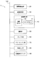
第1実施形態について、図面を参照しつつ説明する。本実施形態の駐車支援装置1は、車両10に搭載され、駐車スペースPSへの車両10の駐車を支援するように構成されている。以下では、図1に示されるように、車両10として、平面視にて略矩形状の車体11を有する一般的な四輪自動車を例に挙げて説明する。また、以下では、車両10の車幅を規定する方向を「車幅方向」とする。図1中では、車幅方向は、紙面左右方向となる。また、以下では、車両10の車幅方向および車両10の高さ方向と直交する方向を「前後方向」とする。また、以下では、車両10の中心を通り、前後方向に延びる仮想線を「車両中心線L」とする。また、以下では、車両中心線Lと平行な方向における一方(すなわち、図1における上方)を「前方」ともいい、他方(すなわち、図1における下方)を「後方」ともいう。また、以下では、車両10の車幅方向における右側を「右側方」ともいい、車両10の車幅方向における左側を「左側方」ともいう。 (First embodiment)
The first embodiment will be described with reference to the drawings. Theparking assistance device 1 of the present embodiment is mounted on a vehicle 10 and is configured to assist the parking of the vehicle 10 in the parking space PS. Hereinafter, as shown in FIG. 1, as the vehicle 10, a general four-wheeled vehicle having a vehicle body 11 having a substantially rectangular shape in a plan view will be described as an example. Further, hereinafter, the direction that defines the vehicle width of the vehicle 10 is referred to as the “vehicle width direction”. In FIG. 1, the vehicle width direction is the left-right direction on the paper surface. Further, hereinafter, a direction orthogonal to the vehicle width direction of the vehicle 10 and the height direction of the vehicle 10 is referred to as a “front-rear direction”. Further, hereinafter, a virtual line that passes through the center of the vehicle 10 and extends in the front-rear direction is referred to as a “vehicle center line L”. In the following, one side (that is, the upper side in FIG. 1) in the direction parallel to the vehicle center line L is also referred to as “front”, and the other (that is, the lower side in FIG. 1) is also referred to as the “rear side”. Further, hereinafter, the right side of the vehicle 10 in the vehicle width direction is also referred to as “right side”, and the left side of the vehicle 10 in the vehicle width direction is also referred to as “left side”.
第1実施形態について、図面を参照しつつ説明する。本実施形態の駐車支援装置1は、車両10に搭載され、駐車スペースPSへの車両10の駐車を支援するように構成されている。以下では、図1に示されるように、車両10として、平面視にて略矩形状の車体11を有する一般的な四輪自動車を例に挙げて説明する。また、以下では、車両10の車幅を規定する方向を「車幅方向」とする。図1中では、車幅方向は、紙面左右方向となる。また、以下では、車両10の車幅方向および車両10の高さ方向と直交する方向を「前後方向」とする。また、以下では、車両10の中心を通り、前後方向に延びる仮想線を「車両中心線L」とする。また、以下では、車両中心線Lと平行な方向における一方(すなわち、図1における上方)を「前方」ともいい、他方(すなわち、図1における下方)を「後方」ともいう。また、以下では、車両10の車幅方向における右側を「右側方」ともいい、車両10の車幅方向における左側を「左側方」ともいう。 (First embodiment)
The first embodiment will be described with reference to the drawings. The
駐車支援装置1は、図2に示されるように、障害物検出部20、画像取得部30、画像表示部40、操舵部50、ブレーキ部60、パワートレイン部70、各種センサ80、自動駐車スイッチ90等を有する構成とされている。そして、これら障害物検出部20、画像取得部30、画像表示部40、操舵部50、ブレーキ部60、パワートレイン部70、各種センサ80、自動駐車スイッチ90は、車載通信バス100を介して接続されている。
As shown in FIG. 2, the parking assistance device 1 includes an obstacle detection unit 20, an image acquisition unit 30, an image display unit 40, a steering unit 50, a brake unit 60, a power train unit 70, various sensors 80, an automatic parking switch. 90 and the like. Then, the obstacle detection unit 20, the image acquisition unit 30, the image display unit 40, the steering unit 50, the brake unit 60, the power train unit 70, various sensors 80, and the automatic parking switch 90 are connected via the in-vehicle communication bus 100. Has been done.
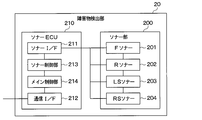
障害物検出部20は、図3に示されるように、ソナー部200、およびソナーECU210等を備えている。具体的には、ソナー部200は、フロント(以下では、Fという)ソナー201、リア(以下では、Rという)ソナー202、左側(以下では、LSという)ソナー203、右側(以下では、RSという)ソナー204を有している。Fソナー201、Rソナー202、LSソナー203、RSソナー204は、探査波を車両10の外側に向けて発信すると共に、障害物による探査波の反射波を含み、車両10と障害物との距離に応じた強度を有する受信波を受信できるように構成されたものである。そして、Fソナー201、Rソナー202、LSソナー203、RSソナー204は、受信波に基づいた検出信号を出力する。なお、本実施形態では、各ソナー201~204が検出部に相当する。
The obstacle detection unit 20 includes a sonar unit 200, a sonar ECU 210, and the like, as shown in FIG. Specifically, the sonar unit 200 includes a front (hereinafter, F) sonar 201, a rear (hereinafter, R) sonar 202, a left (hereinafter, LS) sonar 203, and a right (hereinafter, RS). ) It has a sonar 204. The F sonar 201, the R sonar 202, the LS sonar 203, and the RS sonar 204 transmit the exploration wave toward the outside of the vehicle 10, and include the reflected wave of the exploration wave due to an obstacle, and the distance between the vehicle 10 and the obstacle. It is configured so as to be able to receive a received wave having an intensity corresponding to. Then, the F sonar 201, the R sonar 202, the LS sonar 203, and the RS sonar 204 output detection signals based on the received waves. It should be noted that in the present embodiment, each of the sonars 201 to 204 corresponds to a detection unit.
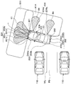
以下、各ソナー201~204の配置箇所について、図1を参照しつつ説明する。なお、図1では、各ソナー201~204の検出範囲R1~R4を理解し易くするため、検出範囲R1~R4にハッチングを施してある。また、後述の図5A~図5Cにおいても、各ソナー201~204の検出範囲R1~R4を理解し易くするため、検出範囲R1~R4に適宜ハッチングを施してある。
The locations of the sonars 201 to 204 will be described below with reference to FIG. In FIG. 1, the detection ranges R1 to R4 are hatched in order to facilitate understanding of the detection ranges R1 to R4 of the sonars 201 to 204. Also, in FIGS. 5A to 5C described later, the detection ranges R1 to R4 are hatched as appropriate to facilitate understanding of the detection ranges R1 to R4 of the sonars 201 to 204.
本実施形態では、図1に示されるように、Fソナー201は、第1~第4Fソナー201a~201dを有し、車両10の前方に位置する障害物を検出できるように、例えば、車体11におけるフロントバンパー12に装着されている。具体的には、第1Fソナー201aは、車体11の左前角部に配置されている。第2Fソナー201bは、車体11の右前角部に配置されている。また、第1Fソナー201aと第2Fソナー201bとは、車両中心線Lを挟んで対称に配置されている。第3Fソナー201cは、第1Fソナー201aと車両中心線Lとの間に配置されている。第4Fソナー201dは、第2Fソナー201bと車両中心線Lとの間に配置されている。また、第3Fソナー201cと第4Fソナー201dとは、車両中心線Lを挟んで対称に配置されている。
In the present embodiment, as shown in FIG. 1, the F-sonar 201 has first to fourth F-sonars 201a to 201d, and can detect an obstacle located in front of the vehicle 10, for example, the vehicle body 11 It is mounted on the front bumper 12 in. Specifically, the first F sonar 201a is arranged at the left front corner of the vehicle body 11. The second F sonar 201b is arranged at the front right corner of the vehicle body 11. Further, the first F sonar 201a and the second F sonar 201b are symmetrically arranged with the vehicle center line L interposed therebetween. The 3rd F sonar 201c is arranged between the 1st F sonar 201a and the vehicle center line L. The fourth F sonar 201d is disposed between the second F sonar 201b and the vehicle center line L. Further, the third F sonar 201c and the fourth F sonar 201d are symmetrically arranged with the vehicle center line L interposed therebetween.
Rソナー202は、第1~第4Rソナー202a~202dを有し、車両10の後方に位置する障害物を検出できるように、例えば、車体11におけるリアバンパー13に装着されている。具体的には、第1Rソナー202aは、車体11の左後角部に配置されている。第2Rソナー202bは、車体11の右後角部に配置されている。また、第1Rソナー202aと第2Rソナー202bとは、車両中心線Lを挟んで対称に配置されている。第3Rソナー202cは、第1Rソナー202aと車両中心線Lとの間に配置されている。第4Rソナー202dは、第2Rソナー202bと車両中心線Lとの間に配置されている。また、第3Rソナー202cと第4Rソナー202dとは、車両中心線Lを挟んで対称に配置されている。
The R sonar 202 has first to fourth R sonars 202a to 202d, and is mounted on, for example, the rear bumper 13 of the vehicle body 11 so that an obstacle located behind the vehicle 10 can be detected. Specifically, the first R sonar 202a is arranged at the left rear corner of the vehicle body 11. The second R sonar 202b is arranged at the right rear corner of the vehicle body 11. Further, the first R sonar 202a and the second R sonar 202b are symmetrically arranged with the vehicle center line L interposed therebetween. The third R sonar 202c is arranged between the first R sonar 202a and the vehicle center line L. The fourth R sonar 202d is arranged between the second R sonar 202b and the vehicle center line L. In addition, the third R sonar 202c and the fourth R sonar 202d are symmetrically arranged with the vehicle center line L interposed therebetween.
なお、本実施形態では、第1~第4Fソナー201a~201dは、隣合うソナーの検出範囲が重複するように配置されている。そして、第1~第4Fソナー201a~201dは、一体的に接続されており、全体として一つの検出信号を出力するように構成されている。つまり、本実施形態では、第1~第4Fソナー201a~201dは、全体として車両10の前方の検出範囲R1を構成している。そして、本実施形態のFソナー201は、第1~第4Fソナー201a~201dのうちの一つが故障した場合には、全体として故障した状態となる。
In this embodiment, the first to fourth F sonars 201a to 201d are arranged so that the detection ranges of adjacent sonars overlap. The first to fourth F sonars 201a to 201d are integrally connected and are configured to output one detection signal as a whole. That is, in the present embodiment, the first to fourth F sonars 201a to 201d constitute the detection range R1 in front of the vehicle 10 as a whole. When one of the first to fourth F sonars 201a to 201d fails, the F sonar 201 of the present embodiment is in a failed state as a whole.
同様に、本実施形態では、第1~第4Rソナー202a~202dは、隣合うソナーの検出範囲が重複するように配置されている。そして、第1~第4Rソナー202a~202dは、一体的に接続されており、全体として一つの検出信号を出力するように構成されている。つまり、本実施形態では、第1~第4Rソナー202a~202dは、全体として車両10の後方の検出範囲R2を構成している。そして、本実施形態のRソナー202は、第1~第4Rソナー202a~202dのうちの一つが故障した場合には、全体として故障した状態となる。
Similarly, in this embodiment, the first to fourth R sonars 202a to 202d are arranged such that the detection ranges of adjacent sonars overlap. The first to fourth R sonars 202a to 202d are integrally connected and are configured to output one detection signal as a whole. That is, in the present embodiment, the first to fourth R sonars 202a to 202d constitute the detection range R2 behind the vehicle 10 as a whole. When one of the first to fourth R sonars 202a to 202d fails, the R sonar 202 of the present embodiment is in a failed state as a whole.
LSソナー203は、第1、第2LSソナー203a、203bを有し、車両10の左側方の障害物を検出できるように、車体11における車幅方向の左側に備えられている。具体的には、第1LSソナー203aは、車体11の前後方向において、左側のドアミラー14と第1Fソナー201aとの間に配置されている。第2LSソナー203bは、車体11の前後方向において、左側のドアパネル15と第1Rソナー202aとの間に配置されている。
The LS sonar 203 has first and second LS sonars 203a and 203b, and is provided on the left side of the vehicle body 11 in the vehicle width direction so that an obstacle on the left side of the vehicle 10 can be detected. Specifically, the first LS sonar 203a is arranged between the left side door mirror 14 and the first F sonar 201a in the front-rear direction of the vehicle body 11. The second LS sonar 203b is arranged between the left door panel 15 and the first R sonar 202a in the front-rear direction of the vehicle body 11.
RSソナー204は、第1、第2RSソナー204a、204bを有し、車両10の右側方の障害物を検出できるように、車体11における車幅方向の右側に備えられている。具体的には、第1RSソナー204aは、車体11の前後方向において、右側のドアミラー16と第2Fソナー201bとの間に配置されている。また、第1LSソナー203aと第1RSソナー204aとは、車両中心線Lを挟んで対称に配置されている。第2RSソナー204bは、車体11における前後方向について、右側のドアパネル17と第2Rソナー202bとの間に配置されている。また、第2LSソナー203bと第2RSソナー204bとは、車両中心線Lを挟んで対称に配置されている。
The RS sonar 204 has first and second RS sonars 204a and 204b, and is provided on the right side of the vehicle body 11 in the vehicle width direction so that an obstacle on the right side of the vehicle 10 can be detected. Specifically, the first RS sonar 204a is disposed between the right side door mirror 16 and the second F sonar 201b in the front-rear direction of the vehicle body 11. Further, the first LS sonar 203a and the first RS sonar 204a are arranged symmetrically with the vehicle center line L interposed therebetween. The second RS sonar 204b is arranged between the right door panel 17 and the second R sonar 202b in the front-rear direction of the vehicle body 11. Further, the second LS sonar 203b and the second RS sonar 204b are arranged symmetrically with the vehicle center line L interposed therebetween.
なお、本実施形態では、第1、第2LSソナー203a、203bは、互いに独立して配置されており、それぞれの検出信号を出力するように構成されている。つまり、本実施形態では、第1LSソナー203aおよび第2LSソナー203bは、それぞれ車両10の左側方の検出範囲R3を構成している。このため、本実施形態では、第1LSソナー203aおよび第2LSソナー203bは、仮にどちらかのソナーが故障等したとしても、全体として故障した状態とはならない。
In the present embodiment, the first and second LS sonars 203a and 203b are arranged independently of each other, and are configured to output their respective detection signals. That is, in the present embodiment, the first LS sonar 203a and the second LS sonar 203b respectively configure the detection range R3 on the left side of the vehicle 10. Therefore, in the present embodiment, the first LS sonar 203a and the second LS sonar 203b will not be in a failure state as a whole even if one of the sonars fails.
同様に、第1、第2RSソナー204a、204bは、互いに独立して配置されており、それぞれの検出信号を出力するように構成されている。つまり、本実施形態では、第1RSソナー204aおよび第2RSソナー204bは、それぞれ車両10の右側方の検出範囲R4を構成している。このため、本実施形態では、第1RSソナー204aおよび第2RSソナー204bは、仮にどちらかのソナーが故障等したとしても、全体として故障した状態とはならない。
Similarly, the first and second RS sonars 204a and 204b are arranged independently of each other and are configured to output respective detection signals. That is, in the present embodiment, each of the first RS sonar 204a and the second RS sonar 204b constitutes the detection range R4 on the right side of the vehicle 10. Therefore, in the present embodiment, the first RS sonar 204a and the second RS sonar 204b will not be in a failure state as a whole even if one of the sonars fails.
ソナーECU210は、図3に示されるように、ソナーI/F211、通信I/F212、ソナー制御部213、メイン制御部214等を備えた構成とされている。ソナーI/F211は、各ソナー201~204とソナー制御部213との間で通信を行うためのインタフェースである。通信I/F212は、メイン制御部214と車載通信バス100との間で通信を行うためのインタフェースである。なお、ECUは、Electronic Control Unitの略であり、後述するECUについても同様である。
As shown in FIG. 3, the sonar ECU 210 is configured to include a sonar I/F 211, a communication I/F 212, a sonar control unit 213, a main control unit 214, and the like. The sonar I/F 211 is an interface for communicating between each of the sonars 201 to 204 and the sonar control unit 213. The communication I/F 212 is an interface for communicating between the main control unit 214 and the vehicle-mounted communication bus 100. The ECU is an abbreviation for Electronic Control Unit, and the same applies to the ECU described later.
ソナー制御部213およびメイン制御部214は、それぞれ図示しないCPU、ROM、RAM、不揮発性RAM等を備えた、いわゆる車載マイクロコンピュータで構成されている。CPUは、Central Processing Unitの略であり、ROMは、Read Only Memoryの略であり、RAMは、Random Access Memoryの略である。そして、ソナー制御部213およびメイン制御部214は、CPUがROM、または不揮発性RAMからプログラム(すなわち、後述の各ルーチン)を読み出して実行することで各種の制御作動を実現する。なお、ROM、または不揮発性RAMには、プログラムの実行の際に用いられる各種のデータ(例えば、初期値、ルックアップテーブル、マップ等)が予め格納されている。また、ROM等の記憶媒体は、非遷移的実体的記憶媒体である。
The sonar control unit 213 and the main control unit 214 are each configured by a so-called in-vehicle microcomputer including a CPU, a ROM, a RAM, a non-volatile RAM, etc., which are not shown. CPU is an abbreviation for Central Processing Unit, ROM is an abbreviation for Read Only Memory, and RAM is an abbreviation for Random Access Memory. Then, the sonar control unit 213 and the main control unit 214 realize various control operations by the CPU reading a program (that is, each routine described below) from the ROM or the non-volatile RAM and executing the program. Various data (for example, initial values, look-up tables, maps, etc.) used when the program is executed are stored in advance in the ROM or the nonvolatile RAM. A storage medium such as a ROM is a non-transitional substantive storage medium.
ソナー制御部213は、Fソナー201、Rソナー202、LSソナー203、RSソナー204とソナーI/F211を介して接続されていると共に、メイン制御部214と接続されている。そして、ソナー制御部213は、各ソナー201~204からの検出信号に基づいて各ソナー201~204が故障しているか否かを判定する。例えば、ソナー制御部213は、検出信号が入力されていない場合には、当該検出信号を入力するソナーに故障が発生していると判定する。また、ソナー制御部213は、所定の閾値を超える検出信号が入力されている場合には、当該検出信号を入力しているソナーに故障が発生していると判定する。そして、ソナー制御部213は、各ソナー201~204からの検出信号と共に、各ソナー201~204の故障状態をメイン制御部214に出力する。
The sonar control unit 213 is connected to the F sonar 201, the R sonar 202, the LS sonar 203, and the RS sonar 204 via the sonar I/F 211, and is also connected to the main control unit 214. Then, the sonar control unit 213 determines whether or not each of the sonars 201 to 204 has a failure based on the detection signal from each of the sonars 201 to 204. For example, when the detection signal is not input, the sonar control unit 213 determines that the sonar that inputs the detection signal has a failure. Further, when the detection signal exceeding the predetermined threshold is input, the sonar control unit 213 determines that the sonar inputting the detection signal has a failure. Then, the sonar control unit 213 outputs the failure state of each of the sonars 201 to 204 to the main control unit 214 together with the detection signal from each of the sonars 201 to 204.
なお、上記のように、本実施形態では、Fソナー201は、第1~第4Fソナー201a~201dが一体的に接続された構成とされている。このため、Fソナー201は、第1~第4Fソナー201a~201dのうちの少なくとも一つが故障している場合には、全体として故障していると判定される。同様に、Rソナー202は、第1~第4Rソナー202a~202dを有しているが、第1~第4Rソナー202a~202dのうちの少なくとも一つのが故障している場合には、全体として故障していると判定される。一方、LSソナー203は、第1LSソナー203aおよび第2LSソナー203bが互いに独立した構成とされている。このため、LSソナー203は、第1LSソナー203aおよび第2LSソナー203bのうちの一方が故障していたとしても全体として故障しているとは判定されず、一部が故障していると判定される。同様に、RSソナー204は、第1RSソナー204aおよび第2RSソナー204bのうちの一方が故障していたとしても全体として故障しているとは判定されず、一部が故障していると判定される。
Note that, as described above, in the present embodiment, the F sonar 201 is configured such that the first to fourth F sonars 201a to 201d are integrally connected. Therefore, when at least one of the first to fourth F sonars 201a to 201d is out of order, the F sonar 201 is determined to be out of order as a whole. Similarly, the R sonar 202 has first to fourth R sonars 202a to 202d, but if at least one of the first to fourth R sonars 202a to 202d is out of order, as a whole. It is determined to be out of order. On the other hand, the LS sonar 203 is configured such that the first LS sonar 203a and the second LS sonar 203b are independent of each other. Therefore, even if one of the first LS sonar 203a and the second LS sonar 203b is out of order, the LS sonar 203 is not determined to be out of order as a whole, but is determined to be partially out of order. It Similarly, even if one of the first RS sonar 204a and the second RS sonar 204b is out of order, the RS sonar 204 is not determined to be out of order as a whole, but is determined to be partially out of order. It
メイン制御部214は、ソナー部200の検出信号、後述するカメラ部300の画像信号、各種センサ80等の検出信号に基づいて所定の処理を行う機能を備えている。具体的には、メイン制御部214は、操舵部50、ブレーキ部60、パワートレイン部70等を適宜制御して車両10の支援走行を実行する機能を備え、具体的には後述するが、車両10の自動駐車処理を実行する機能も備えている。そして、メイン制御部214は、自動駐車処理を実行する場合には、ソナー制御部213から入力される検出信号および故障情報と、後述するカメラ制御部313から入力される画像信号および故障情報に基づいて自動駐車処理を実行する。また、メイン制御部214は、自動駐車処理を実行する場合には、画像表示部40における後述のディスプレイ41に対応する画像を表示させる処理を実行する。
The main control unit 214 has a function of performing a predetermined process based on a detection signal of the sonar unit 200, an image signal of the camera unit 300 described later, and detection signals of various sensors 80 and the like. Specifically, the main control unit 214 has a function of appropriately controlling the steering unit 50, the brake unit 60, the power train unit 70, and the like to execute the assisted traveling of the vehicle 10. Specifically, the vehicle will be described later. It also has a function of executing 10 automatic parking processes. Then, when executing the automatic parking process, the main control unit 214 is based on the detection signal and the failure information input from the sonar control unit 213 and the image signal and the failure information input from the camera control unit 313 described later. To execute automatic parking processing. Further, when executing the automatic parking process, the main control unit 214 executes a process of displaying an image corresponding to the display 41, which will be described later, in the image display unit 40.
画像取得部30は、図4に示されるように、カメラ部300、およびカメラECU310等を備えている。具体的には、カメラ部300は、Fカメラ301、Rカメラ302、LSカメラ303、RSカメラ304を有している。Fカメラ301、Rカメラ302、LSカメラ303、RSカメラ304は、電荷結合素子(すなわち、CCD)等のイメージセンサを備えた構成とされている。そして、Fカメラ301、Rカメラ302、LSカメラ303、RSカメラ304は、車両10の周囲の状況に対応する画像信号を出力する。なお、本実施形態では、各カメラ301~304が撮像部に相当する。
The image acquisition unit 30 includes a camera unit 300, a camera ECU 310, and the like, as shown in FIG. Specifically, the camera unit 300 has an F camera 301, an R camera 302, an LS camera 303, and an RS camera 304. The F camera 301, the R camera 302, the LS camera 303, and the RS camera 304 are configured to include an image sensor such as a charge coupled device (that is, CCD). Then, the F camera 301, the R camera 302, the LS camera 303, and the RS camera 304 output image signals corresponding to the situation around the vehicle 10. In the present embodiment, each of the cameras 301 to 304 corresponds to the image pickup section.
以下、各カメラ301~304の配置箇所について、図1を参照しつつ説明する。なお、図1では、各カメラ301~304の検出範囲をR11~R14として示している。
The locations of the cameras 301 to 304 will be described below with reference to FIG. In FIG. 1, the detection ranges of the cameras 301 to 304 are shown as R11 to R14.
本実施形態では、Fカメラ301は、車両10の前方の検出範囲R11における画像信号を取得できるように、車体11の前方側の部位に装着されている。Rカメラ302は、車両10の後方の検出範囲R12における画像信号を取得できるように、車体11の後方側の部位に装着されている。LSカメラ303は、車両10の左側方の検出範囲R13における画像信号を取得できるように、例えば、左側のドアミラー14に装着されている。RSカメラ304は、車両10の右側方の検出範囲R14における画像信号を取得できるように、右側のドアミラー16に装着されている。
In the present embodiment, the F camera 301 is attached to the front portion of the vehicle body 11 so that the image signal in the detection range R11 in front of the vehicle 10 can be acquired. The R camera 302 is attached to a rear side portion of the vehicle body 11 so that an image signal in the detection range R12 behind the vehicle 10 can be acquired. The LS camera 303 is attached to, for example, the left side door mirror 14 so that an image signal in the detection range R13 on the left side of the vehicle 10 can be acquired. The RS camera 304 is attached to the right side door mirror 16 so as to acquire an image signal in the detection range R14 on the right side of the vehicle 10.
カメラECU310は、カメラI/F311、通信I/F312、カメラ制御部313等を備えた構成とされている。カメラI/F311は、各カメラ301~304とカメラ制御部313との間で通信を行うためのインタフェースである。通信I/F312は、カメラ制御部313と車載通信バス100との間で通信を行うためのインタフェースである。
The camera ECU 310 is configured to include a camera I/F 311, a communication I/F 312, a camera control unit 313, and the like. The camera I/F 311 is an interface for communicating between each of the cameras 301 to 304 and the camera control unit 313. The communication I/F 312 is an interface for performing communication between the camera control unit 313 and the vehicle-mounted communication bus 100.
カメラ制御部313は、ソナー制御部213等と同様に、図示しないCPU、ROM、RAM、不揮発性RAM等を備えた、いわゆる車載マイクロコンピュータで構成されている。そして、カメラ制御部313は、CPUがROM、または不揮発性RAMからプログラム(すなわち、後述の各ルーチン)を読み出して実行することで各種の制御作動を実現する。なお、ROM、または不揮発性RAMには、プログラムの実行の際に用いられる各種のデータ(例えば、初期値、ルックアップテーブル、マップ等)が予め格納されている。また、ROM等の記憶媒体は、非遷移的実体的記憶媒体である。
Like the sonar control unit 213 and the like, the camera control unit 313 is configured by a so-called in-vehicle microcomputer including a CPU, ROM, RAM, non-volatile RAM, and the like, which are not shown. Then, the camera control unit 313 realizes various control operations by the CPU reading a program (that is, each routine described below) from the ROM or the nonvolatile RAM and executing the program. Various data (for example, initial values, look-up tables, maps, etc.) used when the program is executed are stored in advance in the ROM or the nonvolatile RAM. A storage medium such as a ROM is a non-transitional substantive storage medium.
カメラ制御部313は、Fカメラ301、Rカメラ302、LSカメラ303、RSカメラ304とカメラI/F311を介して接続されている。そして、カメラ制御部313は、各カメラ301~304で撮像された画像信号に基づいて各カメラ301~304が故障しているか否かを判定する。例えば、カメラ制御部313は、画像信号が入力されていない場合には、当該画像信号を入力するカメラに故障が発生していると判定する。また、カメラ制御部313は、画像信号が入力されているにも関わらず、特定領域の画像(すなわち、画素)のみが変化していない場合には、当該画像信号を入力するカメラに故障が発生していると判定する。そして、カメラ制御部313は、画像信号と共に、各カメラ301~304の故障状態をメイン制御部214に出力する。
The camera control unit 313 is connected to the F camera 301, the R camera 302, the LS camera 303, and the RS camera 304 via the camera I/F 311. Then, the camera control unit 313 determines whether or not each of the cameras 301 to 304 has a failure based on the image signal captured by each of the cameras 301 to 304. For example, when the image signal is not input, the camera control unit 313 determines that the camera that inputs the image signal has a failure. Further, when only the image (that is, the pixel) in the specific area has not changed despite the image signal being input, the camera control unit 313 causes a failure in the camera that inputs the image signal. It is determined that Then, the camera control unit 313 outputs the failure state of each of the cameras 301 to 304 to the main control unit 214 together with the image signal.
なお、例えば、カメラに水滴や雪等が付着することによって特定領域の画像のみが変化しない場合も想定されるが、このような状態でも画像信号の信頼性が低下する。このため、本実施形態では、このような状態もカメラの故障と判定する。
Note that, for example, it may be assumed that only the image in a specific area does not change due to water droplets, snow, or the like adhering to the camera, but even in such a state, the reliability of the image signal decreases. Therefore, in the present embodiment, such a state is also determined as a camera failure.
画像表示部40は、図2に示されるように、ディスプレイ41および描画ECU42等を備えている。ディスプレイ41は、例えば、インスツルメントパネルの中央付近や、運転席の前方に設けられたコンビネーションメータ内等に配置される。また、ディスプレイ41は、例えば、フルカラー表示が可能なもので構成され、液晶ディスプレイや有機ELディスプレイ等で構成される。なお、ディスプレイ41は、例えば、ヘッドアップディスプレイ等であってもよいし、乗員が操作可能なタッチパネルで構成されていてもよい。
As shown in FIG. 2, the image display unit 40 includes a display 41, a drawing ECU 42, and the like. The display 41 is arranged, for example, near the center of the instrument panel or in a combination meter provided in front of the driver's seat. Further, the display 41 is configured to be capable of full color display, for example, a liquid crystal display or an organic EL display. The display 41 may be, for example, a head-up display or the like, or may be a touch panel that can be operated by an occupant.
描画ECU42は、図示しない描画制御部等を備えており、車両10の周辺地図をディスプレイ41に描画したり、乗員の操作に基づいた画像をディスプレイ41に描画する。また、描画ECU42は、自動駐車処理を行っている場合には、自動駐車処理に対応する画像をディスプレイ41に描画する。この場合、描画ECU42は、各ソナー201~204、および各カメラ301~304に故障が発生した場合には、ディスプレイ41に対応する画像を描画する。
The drawing ECU 42 includes a drawing control unit (not shown) and the like, and draws a peripheral map of the vehicle 10 on the display 41, or draws an image based on an operation of an occupant on the display 41. Further, the drawing ECU 42 draws an image corresponding to the automatic parking process on the display 41 when the automatic parking process is being performed. In this case, the drawing ECU 42 draws an image corresponding to the display 41 when a failure occurs in each of the sonars 201 to 204 and each of the cameras 301 to 304.
操舵部50は、図示しない操舵センサおよび操舵ECU等を備えている。そして、操舵部50は、車両10の支援走行が実行される場合には、メイン制御部214から入力される制御信号に応じて車両10の走行方向を制御する。
The steering section 50 includes a steering sensor, a steering ECU, and the like, which are not shown. Then, when the assisted traveling of the vehicle 10 is executed, the steering unit 50 controls the traveling direction of the vehicle 10 according to the control signal input from the main control unit 214.
ブレーキ部60は、図示しないブレーキセンサおよびブレーキECU等を備えている。そして、ブレーキ部60は、車両10の支援走行が実行される場合には、メイン制御部214から入力される制御信号に応じて制動力を発生させ、車両10を自動的に停止させる。ブレーキ部60は、例えば、油圧式ブレーキが備えられている場合には、油圧式ブレーキの液圧回路に設けられているアクチュエータを制御することで制動力を調整する。また、ブレーキ部60は、例えば、駆動原としてモータが備えられている場合には、モータへの供給電力を制御することによる回生ブレーキによって制動力を調整する。
The brake unit 60 includes a brake sensor, a brake ECU, and the like, which are not shown. Then, when the assisted traveling of the vehicle 10 is executed, the brake unit 60 generates a braking force according to the control signal input from the main control unit 214, and automatically stops the vehicle 10. For example, when a hydraulic brake is provided, the brake unit 60 adjusts the braking force by controlling an actuator provided in the hydraulic circuit of the hydraulic brake. In addition, for example, when a motor is provided as a driving source, the brake unit 60 adjusts the braking force by regenerative braking by controlling the electric power supplied to the motor.
パワートレイン部70は、車両10に搭載されている駆動源、当該駆動源の駆動力を駆動輪に伝達する機構、パワートレインECU等を備えている。そして、パワートレイン部70は、車両10の支援走行が実行される場合には、メイン制御部214から入力される制御信号に応じて駆動力を調整する。パワートレイン部70は、例えば、駆動源が内燃機関である場合には、スロットル装置の開度や燃料噴射量を制御して駆動力を調整する。また、パワートレイン部70は、例えば、駆動源がモータである場合には、モータへの供給電力を制御することで駆動力を調整する。
The power train unit 70 includes a drive source mounted on the vehicle 10, a mechanism for transmitting the drive force of the drive source to the drive wheels, a power train ECU, and the like. Then, when the assisted traveling of the vehicle 10 is executed, the power train unit 70 adjusts the driving force according to the control signal input from the main control unit 214. For example, when the drive source is an internal combustion engine, the power train unit 70 controls the opening degree of the throttle device and the fuel injection amount to adjust the driving force. In addition, for example, when the drive source is a motor, the power train unit 70 adjusts the driving force by controlling the electric power supplied to the motor.
各種センサ80は、車速センサ、ジャイロセンサ、シフトポジションセンサ等を含むものである。そして、各種センサ80は、それぞれ各種センサ80で検出される検出信号をメイン制御部214に出力する。
The various sensors 80 include a vehicle speed sensor, a gyro sensor, a shift position sensor, and the like. Then, the various sensors 80 output detection signals respectively detected by the various sensors 80 to the main control unit 214.
自動駐車スイッチ90は、乗員が車両10を自動駐車させるためのスイッチであり、例えば、インスツルメントパネルの中央付近に備えられる。そして、メイン制御部214は、自動駐車スイッチ90が操作されると車両10の自動駐車処理を実行する。なお、自動駐車スイッチ90は、ディスプレイ41がタッチパネルで構成される場合には、ディスプレイ41に表示されるようにしてもよい。
The automatic parking switch 90 is a switch for the passenger to automatically park the vehicle 10, and is provided, for example, near the center of the instrument panel. Then, when the automatic parking switch 90 is operated, the main control unit 214 executes the automatic parking process of the vehicle 10. The automatic parking switch 90 may be displayed on the display 41 when the display 41 is a touch panel.
以上が本実施形態における駐車支援装置1の構成である。次に、本実施形態の駐車支援装置1のメイン制御部214が実行する自動駐車処理について説明する。なお、以下では、上記車両10を自車両10として説明する。また、以下では、自車両10を並列駐車する例を説明するが、自車両10を縦列駐車する場合もメイン制御部214の処理内容は同様である。並列駐車とは、駐車車両と自車両10とが自車両10における車幅方向に沿って配列するように、自車両10を駐車する駐車態様である。縦列駐車とは、駐車車両と自車両10とが自車両10の前後方向に沿って配列するように、自車両10を駐車する駐車態様である。
The above is the configuration of the parking assistance device 1 in the present embodiment. Next, the automatic parking process executed by the main control unit 214 of the parking assistance device 1 of the present embodiment will be described. In addition, below, the said vehicle 10 is demonstrated as the own vehicle 10. Further, although an example in which the own vehicle 10 is parked in parallel will be described below, the processing content of the main control unit 214 is the same when the own vehicle 10 is parked in parallel. The parallel parking is a parking mode in which the vehicle 10 is parked so that the parked vehicle and the vehicle 10 are arranged along the vehicle width direction of the vehicle 10. Parallel parking is a parking mode in which the vehicle 10 is parked so that the parked vehicle and the vehicle 10 are arranged along the front-rear direction of the vehicle 10.
まず、自動駐車処理の際の自車両10の動きについて説明する。なお、自動駐車処理は、上記のように自動駐車スイッチ90が操作された際に実行される。また、以下では、図5A~図5Cに示されるように、自車両10の左側方に駐車スペースPSがあり、当該駐車スペースPSを挟んで両側に駐車車両110が駐車されている例を説明する。
First, the movement of the vehicle 10 during the automatic parking process will be described. The automatic parking process is executed when the automatic parking switch 90 is operated as described above. Further, in the following, as shown in FIGS. 5A to 5C, an example will be described in which the parking space PS is on the left side of the vehicle 10, and the parking vehicles 110 are parked on both sides of the parking space PS. ..
まず、自車両10を自動駐車処理によって駐車する場合には、図5Aに示されるように、駐車スペースPSを検出する駐車スペース検出処理が実行される。次に、自車両10を自動駐車処理によって駐車する場合には、図5Bに示されるように、駐車スペースPSに自車両10を駐車するために自車両10の角度を調整する処理(以下では、単に角度調整処理という)が実行される。その後、自車両10を自動駐車によって駐車する場合には、図5Cに示されるように、駐車スペースPSに自車両10を駐車するための駐車処理が実行される。
First, when the vehicle 10 is parked by the automatic parking process, the parking space detection process for detecting the parking space PS is executed as shown in FIG. 5A. Next, in the case of parking the own vehicle 10 by the automatic parking process, as shown in FIG. 5B, a process of adjusting the angle of the own vehicle 10 to park the own vehicle 10 in the parking space PS (hereinafter, The angle adjustment process) is executed. After that, when the host vehicle 10 is parked by automatic parking, the parking process for parking the host vehicle 10 in the parking space PS is executed as shown in FIG. 5C.
なお、メイン制御部214は、自動駐車処理を実行する場合には、周知のように、操舵部50、パワートレイン部70、ブレーキ部60等に各種制御信号を出力して制御することにより、自車両10の進行方向や自車両10の車速等を制御する。そして、メイン制御部214は、駐車スペースPSを検出した場合には、駐車スペースPSまでの経路を導出し、当該経路に沿って自車両10の進行を制御する。また、メイン制御部214は、駐車スペース検出処理を実行する場合には、対応する画像をディスプレイ41に表示させる。
When executing the automatic parking process, the main control unit 214 outputs various control signals to the steering unit 50, the power train unit 70, the brake unit 60, and the like to control the self-parking process. The traveling direction of the vehicle 10 and the vehicle speed of the host vehicle 10 are controlled. When the parking space PS is detected, the main control unit 214 derives a route to the parking space PS and controls the traveling of the host vehicle 10 along the route. In addition, when executing the parking space detection processing, the main control unit 214 causes the display 41 to display a corresponding image.
次に、自動駐車処理の際に使用する検出信号を取得するソナー201~204および画像信号を取得するカメラ301~303と、メイン制御部214の処理について説明する。
Next, the processes of the main control unit 214 and the sonars 201 to 204 that acquire detection signals and the cameras 301 to 303 that acquire image signals used in the automatic parking process will be described.
駐車スペース検出処理では、メイン制御部214は、図5Aに示されるように、車両10を前進させつつ、車両10の左側方の駐車スペースPSを検出する。この場合、メイン制御部214は、Fソナー201の検出信号およびFカメラ301の画像信号に基づいて車両10の前方の状態を認識して車両10を前進させる。また、メイン制御部214は、LSソナー203の検出信号およびLSカメラ303の画像信号に基づいて車両10の左側方の状態を認識することで駐車スペースPSを検出する。
In the parking space detection process, the main control unit 214 detects the parking space PS on the left side of the vehicle 10 while moving the vehicle 10 forward, as shown in FIG. 5A. In this case, the main control unit 214 recognizes the front state of the vehicle 10 based on the detection signal of the F sonar 201 and the image signal of the F camera 301, and moves the vehicle 10 forward. Further, the main control unit 214 detects the parking space PS by recognizing the state on the left side of the vehicle 10 based on the detection signal of the LS sonar 203 and the image signal of the LS camera 303.
この際、図6Aに示されるように、メイン制御部214は、Fソナー201、Fカメラ301、LSソナー203、LSカメラ303が正常である場合には、通常の駐車スペース検出処理である第1駐車スペース検出処理を実行する。
At this time, as shown in FIG. 6A, when the F sonar 201, the F camera 301, the LS sonar 203, and the LS camera 303 are normal, the main control unit 214 is the first parking space detection process, which is the first parking space detection process. Car parking space detection processing is executed.
また、メイン制御部214は、Fソナー201およびFカメラ301の両方が故障している場合には、車両10の前方の状態を認識できないため、駐車スペース検出処理を実行しない。同様に、メイン制御部214は、LSソナー203およびLSカメラ303の両方が故障している場合には、車両10の左側方の状態を認識できないため、駐車スペース検出処理を実行しない。なお、ここでのLSソナー203の故障とは、第1LSソナー203aおよび第2LSソナー203bが故障している状態のことである。
Further, when both the F-sonar 201 and the F-camera 301 are out of order, the main control unit 214 cannot recognize the state in front of the vehicle 10, and therefore does not execute the parking space detection process. Similarly, when both the LS sonar 203 and the LS camera 303 are out of order, the main control unit 214 cannot recognize the state on the left side of the vehicle 10, and therefore does not execute the parking space detection process. The failure of the LS sonar 203 here means a state in which the first LS sonar 203a and the second LS sonar 203b are in failure.
一方、メイン制御部214は、Fソナー201およびFカメラ301の一方が故障しており、LSソナー203およびLSカメラ303の少なくとも一方が正常である場合には、第1駐車スペース検出処理と異なる第2駐車スペース検出処理を実行する。また、メイン制御部214は、LSソナー203およびLSカメラ303の一方が故障しており、Fソナー201およびFカメラ301の少なくとも一方が正常である場合には、第2駐車スペース検出処理を実行する。
On the other hand, when one of the F sonar 201 and the F camera 301 is out of order and at least one of the LS sonar 203 and the LS camera 303 is normal, the main control unit 214 differs from the first parking space detection process. 2 Carry out parking space detection processing. Further, when one of the LS sonar 203 and the LS camera 303 is out of order and at least one of the F sonar 201 and the F camera 301 is normal, the main control unit 214 executes the second parking space detection process. ..
この場合、メイン制御部214は、LSカメラ303が故障している場合には、LSソナー203の検出信号のみを用いて駐車スペースPSを検出する。但し、メイン制御部214は、LSソナー203の検出信号のみを用いて駐車スペースPSを検出する場合、LSソナー203の検出信号から駐車車両110を認識して駐車スペースPSを検出する。このため、メイン制御部214は、駐車車両110が存在しない場合には駐車スペース検出処理を完了させることができない。したがって、メイン制御部214は、駐車車両110が駐車されていない場合には駐車スペース検出処理の完了が困難であることを報知する画像をディスプレイ41に表示させる。
In this case, when the LS camera 303 is out of order, the main control unit 214 detects the parking space PS using only the detection signal of the LS sonar 203. However, when detecting the parking space PS using only the detection signal of the LS sonar 203, the main control unit 214 recognizes the parked vehicle 110 from the detection signal of the LS sonar 203 and detects the parking space PS. Therefore, the main control unit 214 cannot complete the parking space detection process when the parked vehicle 110 does not exist. Therefore, the main control unit 214 causes the display 41 to display an image notifying that it is difficult to complete the parking space detection process when the parked vehicle 110 is not parked.
また、メイン制御部214は、LSソナー203が故障している場合には、LSカメラ303の画像信号のみを用いて駐車スペースPSを検出する。但し、メイン制御部214は、LSカメラ303の画像信号のみを用いて駐車スペースPSを検出する場合、LSカメラ303の画像信号から白線WLを認識して駐車スペースPSを検出する。このため、メイン制御部214は、白線WLが存在しない場合には駐車スペース検出処理を完了することができない。したがって、メイン制御部214は、白線WLが存在しない場合には駐車スペース検出処理の完了が困難であることを報知する画像をディスプレイ41に表示させる。
Further, when the LS sonar 203 is out of order, the main control unit 214 detects the parking space PS using only the image signal of the LS camera 303. However, when detecting the parking space PS using only the image signal of the LS camera 303, the main control unit 214 recognizes the white line WL from the image signal of the LS camera 303 and detects the parking space PS. Therefore, the main control unit 214 cannot complete the parking space detection process when the white line WL does not exist. Therefore, when the white line WL does not exist, the main control unit 214 causes the display 41 to display an image notifying that it is difficult to complete the parking space detection process.
さらに、本実施形態では、LSソナー203は、第1LSソナー203aおよび第2LSソナー203bを有しており、第1LSソナー203aおよび第2LSソナー203bは互いに独立している。このため、メイン制御部214は、第1LSソナー203aおよび第2LSソナー203bの一方が故障している場合にはLSソナー203の一部が故障であると判定し、第2駐車スペース検出処理を実行する。この場合、メイン制御部214は、LSカメラ303が正常である場合には、正常であるLSソナーの検出信号およびLSカメラ303の画像信号を用いた第2駐車スペース検出処理を実行する。また、メイン制御部214は、LSカメラ303が故障している場合には、正常であるLSソナーの検出信号のみを用いた第2駐車スペース検出処理を実行する。つまり、メイン制御部214は、LSカメラ303が故障している場合には、駐車車両110が駐車されていないと駐車スペース検出処理の完了が困難となる駐車スペース検出処理を実行する。
Furthermore, in the present embodiment, the LS sonar 203 has a first LS sonar 203a and a second LS sonar 203b, and the first LS sonar 203a and the second LS sonar 203b are independent of each other. Therefore, when one of the first LS sonar 203a and the second LS sonar 203b is out of order, the main control unit 214 determines that part of the LS sonar 203 is out of order, and executes the second parking space detection process. To do. In this case, when the LS camera 303 is normal, the main control unit 214 executes the second parking space detection process using the normal LS sonar detection signal and the image signal of the LS camera 303. Further, when the LS camera 303 is out of order, the main control unit 214 executes the second parking space detection process using only the detection signal of the normal LS sonar. That is, when the LS camera 303 is out of order, the main control unit 214 executes the parking space detection process that makes it difficult to complete the parking space detection process unless the parked vehicle 110 is parked.
但し、本実施形態では、Fソナー201は、第1~第4Fソナー201a~201dが一体化されている。このため、メイン制御部214は、第1~第4Fソナー201a~201dの少なくとも一つが故障していれば全体としてFソナー201が故障していると判定する。なお、本実施形態の第2駐車スペース検出処理は、上記のように、第1駐車スペース検出処理より制限のある処理となる。
However, in the present embodiment, the F sonar 201 is integrated with the first to fourth F sonars 201a to 201d. Therefore, the main control unit 214 determines that the F sonar 201 as a whole has failed if at least one of the first to fourth F sonars 201a to 201d has failed. It should be noted that the second parking space detection process of this embodiment is a process that is more limited than the first parking space detection process, as described above.
次の角度調整処理では、メイン制御部214は、図5Bに示されるように、検出した駐車スペースPSに自車両10を駐車させるため、駐車スペースPSに対する自車両10の角度を調整する。この場合、図5Bの例では、自車両10を右前方に進行させることによって自車両10の角度を調整する。このため、メイン制御部214は、Fソナー201の検出信号およびFカメラ301の画像信号に基づいて車両10の前方の状態を認識する。また、メイン制御部214は、RSソナー204の検出信号およびRSカメラ304の画像信号に基づいて車両10の右側方の状態を認識する。そして、メイン制御部214は、これらの認識に基づいて角度調整処理を実行する。
In the next angle adjustment process, as shown in FIG. 5B, the main control unit 214 adjusts the angle of the host vehicle 10 with respect to the parking space PS in order to park the host vehicle 10 in the detected parking space PS. In this case, in the example of FIG. 5B, the angle of the host vehicle 10 is adjusted by moving the host vehicle 10 to the front right. Therefore, the main control unit 214 recognizes the state in front of the vehicle 10 based on the detection signal of the F sonar 201 and the image signal of the F camera 301. Further, the main control unit 214 recognizes the right side state of the vehicle 10 based on the detection signal of the RS sonar 204 and the image signal of the RS camera 304. Then, the main control unit 214 executes the angle adjustment processing based on these recognitions.
この際、図6Bに示されるように、メイン制御部214は、Fソナー201、Fカメラ301、RSソナー204、RSカメラ304が正常である場合には、通常の角度調整処理である第1角度調整処理を実行する。
At this time, as shown in FIG. 6B, the main control unit 214, when the F sonar 201, the F camera 301, the RS sonar 204, and the RS camera 304 are normal, the first angle that is a normal angle adjustment process. Perform adjustment processing.
また、メイン制御部214は、Fソナー201およびFカメラ301の両方が故障している場合には、車両10の前方の状態を認識できないため、角度調整処理を実行しない。同様に、メイン制御部214は、RSソナー204およびRSカメラ304の両方が故障している場合には、車両10の右側方の状態を認識できないため、角度調整処理を実行しない。なお、ここでのRSソナー204の故障とは、第1RSソナー204aおよび第2RSソナー204bが故障している状態のことである。
Further, when both the F-sonar 201 and the F-camera 301 are out of order, the main control unit 214 cannot recognize the state in front of the vehicle 10, and therefore does not execute the angle adjustment processing. Similarly, when both the RS sonar 204 and the RS camera 304 are out of order, the main control unit 214 cannot recognize the state on the right side of the vehicle 10, and therefore does not execute the angle adjustment process. The failure of the RS sonar 204 here means a state in which the first RS sonar 204a and the second RS sonar 204b have a failure.
一方、メイン制御部214は、Fソナー201およびFカメラ301の一方が故障しており、RSソナー204およびRSカメラ304の少なくとも一方が正常である場合には、第1角度調整処理と異なる第2角度調整処理を実行する。同様に、メイン制御部214は、RSソナー204およびRSカメラ304の一方が故障しており、Fソナー201およびFカメラ301の少なくとも一方が正常である場合には、第2角度調整処理を実行する。つまり、メイン制御部214は、車両10の前方および右側方の状態が認識可能であれば、Fソナー201、Fカメラ301、RSソナー204およびRSカメラ304の少なくとも1つに故障が発生していたとしても、第2角度調整処理を実行する。そして、メイン制御部214は、第2角度調整処理を行っている場合には、第2角度調整処理を行っていることを示す画像をディスプレイ41に表示させる。
On the other hand, when one of the F sonar 201 and the F camera 301 is out of order and at least one of the RS sonar 204 and the RS camera 304 is normal, the main control unit 214 differs from the first angle adjustment process in the second angle adjustment process. Executes angle adjustment processing. Similarly, when one of the RS sonar 204 and the RS camera 304 is out of order and at least one of the F sonar 201 and the F camera 301 is normal, the main control unit 214 executes the second angle adjustment processing. .. That is, if the front and right sides of the vehicle 10 can be recognized, the main control unit 214 has failed in at least one of the F sonar 201, the F camera 301, the RS sonar 204, and the RS camera 304. Also, the second angle adjustment processing is executed. Then, when the second angle adjustment processing is being performed, the main control unit 214 causes the display 41 to display an image indicating that the second angle adjustment processing is being performed.
さらに、本実施形態では、RSソナー204は、第1RSソナー204aおよび第2RSソナー204bを有しており、第1RSソナー204aおよび第2RSソナー204bは互いに独立している。このため、メイン制御部214は、第1RSソナー204aおよび第2RSソナー204bの一方が故障している場合にはRSソナー204の一部が故障であると判定し、第2角度調整処理を実行する。この場合、メイン制御部214は、RSカメラ304が正常である場合には、正常であるRSソナーの検出信号およびRSカメラ304の画像信号を用いた第2角度調整処理を実行する。また、メイン制御部214は、RSカメラ304が故障している場合には、正常であるRSソナーの検出信号のみを用いた第2角度調整処理を実行する。なお、本実施形態の第2角度調整処理は、上記のように、第1角度調整処理より制限のある処理となる。
Further, in the present embodiment, the RS sonar 204 has a first RS sonar 204a and a second RS sonar 204b, and the first RS sonar 204a and the second RS sonar 204b are independent of each other. Therefore, when one of the first RS sonar 204a and the second RS sonar 204b is out of order, the main control unit 214 determines that part of the RS sonar 204 is out of order, and executes the second angle adjustment processing. .. In this case, when the RS camera 304 is normal, the main control unit 214 executes the second angle adjustment process using the normal detection signal of the RS sonar and the image signal of the RS camera 304. Further, when the RS camera 304 is out of order, the main control unit 214 executes the second angle adjustment processing using only the detection signal of the normal RS sonar. It should be noted that the second angle adjustment process of the present embodiment is a process that is more limited than the first angle adjustment process as described above.
続く駐車処理では、メイン制御部214は、図5Cに示されるように、駐車スペースPSに自車両10を駐車する。この場合、図5Cの例では、自車両10を左後方に進行させることによって自車両10を駐車スペースPSに駐車する。このため、メイン制御部214は、Rソナー202の検出信号およびRカメラ302の画像信号に基づいて車両10の後方の状態を認識する。また、メイン制御部214は、RSソナー204の検出信号およびRSカメラ304の画像信号に基づいて車両10の右側方の状態を認識する。そして、メイン制御部214は、これらの認識に基づいて駐車スペースPSに自車両10を駐車する。
In the subsequent parking process, the main control unit 214 parks the vehicle 10 in the parking space PS, as shown in FIG. 5C. In this case, in the example of FIG. 5C, the vehicle 10 is parked in the parking space PS by moving the vehicle 10 to the left rear. Therefore, the main control unit 214 recognizes the state behind the vehicle 10 based on the detection signal of the R sonar 202 and the image signal of the R camera 302. Further, the main control unit 214 recognizes the right side state of the vehicle 10 based on the detection signal of the RS sonar 204 and the image signal of the RS camera 304. Then, the main control unit 214 parks the vehicle 10 in the parking space PS based on these recognitions.
この際、図6Cに示されるように、メイン制御部214は、Rソナー202、Rカメラ302、RSソナー204、RSカメラ304が正常である場合には、通常の駐車処理である第1駐車処理を実行する。
At this time, as shown in FIG. 6C, the main control unit 214, when the R sonar 202, the R camera 302, the RS sonar 204, and the RS camera 304 are normal, the first parking process which is a normal parking process. To execute.
また、メイン制御部214は、Rソナー202およびRカメラ302の両方が故障している場合には、車両10の後方の状態を認識できないため、駐車処理を実行しない。同様に、メイン制御部214は、RSソナー204およびRSカメラ304の両方が故障している場合には、車両10の右側方の状態を認識できないため、駐車処理を実行しない。なお、ここでのRSソナー204の故障とは、第1RSソナー204aおよび第2RSソナー204bが故障している状態のことである。
Further, when both the R sonar 202 and the R camera 302 are out of order, the main control unit 214 cannot recognize the state behind the vehicle 10, and therefore does not execute the parking process. Similarly, when both the RS sonar 204 and the RS camera 304 are out of order, the main control unit 214 cannot recognize the state on the right side of the vehicle 10, and therefore does not execute the parking process. The failure of the RS sonar 204 here means a state in which the first RS sonar 204a and the second RS sonar 204b have a failure.
一方、メイン制御部214は、Rソナー202およびRカメラ302の一方が故障しており、RSソナー204およびRSカメラ304の少なくとも一方が正常である場合には、第1駐車処理と異なる第2駐車処理を実行する。同様に、メイン制御部214は、RSソナー204およびRSカメラ304の一方が故障しており、Fソナー201およびFカメラ301の少なくとも一方が正常である場合には、第2駐車処理を実行する。つまり、メイン制御部214は、車両10の後方および右側方の状態が認識可能であれば、Rソナー202、Rカメラ302、RSソナー204およびRSカメラ304の少なくとも一つに故障が発生していたとしても、第2駐車処理を実行する。そして、メイン制御部214は、第2駐車処理を行っている場合には、第2駐車処理を行っていることを示す画像をディスプレイ41に表示させる。
On the other hand, when one of the R sonar 202 and the R camera 302 is out of order and at least one of the RS sonar 204 and the RS camera 304 is normal, the main control unit 214 performs the second parking different from the first parking process. Execute the process. Similarly, when one of the RS sonar 204 and the RS camera 304 is out of order and at least one of the F sonar 201 and the F camera 301 is normal, the main control unit 214 executes the second parking process. That is, if the main controller 214 can recognize the rear and right sides of the vehicle 10, at least one of the R sonar 202, the R camera 302, the RS sonar 204, and the RS camera 304 has a failure. Also, the second parking process is executed. Then, when the second parking process is being performed, the main control unit 214 causes the display 41 to display an image indicating that the second parking process is being performed.
さらに、上記角度調整処理と同様に、メイン制御部214は、第1RSソナー204aおよび第2RSソナー204bの一方が正常であれば、RSソナー204の一部が故障であると判定し、第2駐車処理を実行する。この場合、メイン制御部214は、RSカメラ304が正常である場合には、正常であるRSソナーの検出信号およびRSカメラ304の画像信号を用いた第2駐車処理を実行する。また、メイン制御部214は、RSカメラ304が故障している場合には、正常であるRSソナーの検出信号のみを用いた第2駐車処理を実行する。
Further, similar to the angle adjustment processing, if one of the first RS sonar 204a and the second RS sonar 204b is normal, the main control unit 214 determines that a part of the RS sonar 204 is in failure, and the second parking is performed. Execute the process. In this case, when the RS camera 304 is normal, the main control unit 214 executes the second parking process using the normal detection signal of the RS sonar and the image signal of the RS camera 304. In addition, when the RS camera 304 is out of order, the main control unit 214 executes the second parking process using only the detection signal of the normal RS sonar.
但し、本実施形態では、Rソナー202は、第1~第4Rソナー202a~202dが一体化されている。このため、メイン制御部214は、第1~第4Rソナー202a~202aの少なくとも一つが故障していれば全体としてRソナー202が故障していると判定する。なお、本実施形態の第2駐車処理は、上記のように、第1駐車処理より制限のある処理となる。
However, in the present embodiment, the R sonar 202 is integrated with the first to fourth R sonars 202a to 202d. Therefore, the main control unit 214 determines that the R sonar 202 as a whole has failed if at least one of the first to fourth R sonars 202a to 202a has failed. The second parking process of the present embodiment is a process that is more limited than the first parking process, as described above.
また、本実施形態では、メイン制御部214は、自動駐車処理を行っている際に障害物を検知した場合には、車両10を自動的に緊急停止させる緊急ブレーキ制御(すなわち、自動ブレーキ制御)も実行する。つまり、メイン制御部214は、緊急ブレーキが実行可能となる構成とされている。例えば、メイン制御部214は、角度調整処理を実行している途中で障害物を検知して車両10が当該障害物と接触し得ると判定した場合には、緊急ブレーキ制御を実行する。そして、メイン制御部214は、ディスプレイ41に緊急ブレーキ制御を実行して車両10を停止させたことを報知する。この場合、本実施形態では、メイン制御部214は、緊急ブレーキ制御を実行した後に乗員が再び自動駐車スイッチ90を操作した場合には、停止した処理を再開する。
Further, in the present embodiment, the main control unit 214 automatically stops the vehicle 10 in an emergency when an obstacle is detected during the automatic parking process (i.e., automatic brake control). Also run. That is, the main control unit 214 is configured to be able to execute emergency braking. For example, when the main control unit 214 detects an obstacle during the execution of the angle adjustment process and determines that the vehicle 10 may come into contact with the obstacle, the main control unit 214 executes the emergency brake control. Then, the main control unit 214 notifies the display 41 that the vehicle 10 has been stopped by executing the emergency brake control. In this case, in the present embodiment, the main control unit 214 restarts the stopped processing when the occupant operates the automatic parking switch 90 again after executing the emergency brake control.
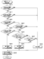
続いて、メイン制御部214が行う自動駐車処理の具体的な処理内容について、図7~図10を参照しつつ説明する。なお、メイン制御部214は、上記のように、自動駐車スイッチ90が操作されると以下の処理を実行する。また、メイン制御部214は、上記のように、操舵部50、パワートレイン部70、ブレーキ部60等に各種制御信号を出力して制御することによって自動駐車処理を実行する。さらに、メイン制御部214は、自動駐車処理を行っている際に障害物を検知した場合には緊急ブレーキ制御を実行して自動駐車処理を停止する。この場合は、例えば、自動駐車スイッチ90が再度操作されることにより、メイン制御部214は、停止した処理を再開する。また、本実施形態では、自動駐車処理を行っている際、乗員のパワートレイン部70への操作(例えば、アクセルペダル操作)は無効とされ、ブレーキ部60への操作(例えば、ブレーキペダル操作)は有効とされている。
Next, specific processing contents of the automatic parking processing performed by the main control unit 214 will be described with reference to FIGS. 7 to 10. The main control unit 214 executes the following processing when the automatic parking switch 90 is operated as described above. In addition, the main control unit 214 executes the automatic parking process by outputting and controlling various control signals to the steering unit 50, the power train unit 70, the brake unit 60, etc. as described above. Further, when the main control unit 214 detects an obstacle during the automatic parking process, the main control unit 214 executes the emergency brake control to stop the automatic parking process. In this case, for example, when the automatic parking switch 90 is operated again, the main control unit 214 restarts the stopped processing. Further, in the present embodiment, when the automatic parking process is performed, the operation of the occupant on the power train unit 70 (for example, accelerator pedal operation) is invalidated, and the operation on the brake unit 60 (for example, brake pedal operation). Is valid.
まず、図7に示されるように、メイン制御部214は、ステップS101にて、各ソナー201~204で検出された検出信号、および各ソナー201~204の故障情報を把握する。なお、各ソナー201~204の故障情報は、上記のように、ソナー制御部213にて各ソナー201~204の故障判定が行われることでソナー制御部213から入力される。
First, as shown in FIG. 7, in step S101, the main control unit 214 grasps the detection signals detected by the sonars 201 to 204 and the failure information of the sonars 201 to 204. The failure information of the sonars 201 to 204 is input from the sonar control section 213 by the failure determination of the sonars 201 to 204 performed by the sonar control section 213 as described above.
次に、メイン制御部214は、ステップS102にて、各カメラ301~304で撮像された画像信号、および各カメラ301~304の故障情報を把握する。なお、各カメラ301~304の故障情報は、上記のように、カメラ制御部313にて各カメラ301~304の故障判定が行われることでカメラ制御部313から入力される。
Next, in step S102, the main control unit 214 grasps the image signals captured by the cameras 301 to 304 and the failure information of the cameras 301 to 304. The failure information of each of the cameras 301 to 304 is input from the camera controller 313 by the failure determination of each of the cameras 301 to 304 performed by the camera controller 313 as described above.
続いて、メイン制御部214は、ステップS103にて、自動駐車処理の状態を把握する。すなわち、メイン制御部214は、駐車スペース検出処理、角度調整処理、または駐車処理のいずれの処理を実行すべきなのかを把握する。なお、この判定は、例えば、各処理を行う際に適宜処理内容をRAM等に記憶させ、記憶された情報を読み出すことによって実現される。また、ここでの判定は、各処理を処理している場合に加え、各処理を開始する場合も同様の判定がされる。例えば、メイン制御部214が駐車スペース検出処理中であると判定する場合には、駐車スペース検出処理を実行している場合に加え、駐車スペース検出処理を開始する場合も含まれる。
Subsequently, the main control unit 214 grasps the state of the automatic parking process in step S103. That is, the main control unit 214 grasps which of the parking space detection process, the angle adjustment process, and the parking process should be executed. It should be noted that this determination is realized, for example, by appropriately storing the processing content in the RAM or the like when performing each processing, and reading the stored information. The determination here is made in the same manner not only when each process is being processed but also when each process is started. For example, when the main control unit 214 determines that the parking space detection process is being performed, it includes the case where the parking space detection process is started and the case where the parking space detection process is started.
メイン制御部214は、ステップS104にて、駐車スペース検出処理中であるか否かを判定する。そして、メイン制御部214は、駐車スペース検出処理中であると判定した場合には(すなわち、ステップS104:YES)、ステップS105にて駐車スペース検出処理を実行する。一方、メイン制御部214は、駐車スペース検出処理中でないと判定した場合には(すなわち、ステップS104:NO)、ステップS106にて角度調整処理中であるか否かを判定する。
The main control unit 214 determines in step S104 whether or not the parking space detection process is being performed. Then, when determining that the parking space detection process is being performed (that is, step S104: YES), the main control unit 214 executes the parking space detection process in step S105. On the other hand, when determining that the parking space detection process is not being performed (that is, step S104: NO), the main control unit 214 determines whether the angle adjustment process is being performed at step S106.
メイン制御部214は、角度調整処理中であると判定した場合には(すなわち、ステップS106:YES)、ステップS107にて角度調整処理を実行する。これに対し、メイン制御部214は、角度調整処理中でないと判定した場合には(すなわち、ステップS106:NO)、ステップS108にて駐車処理を実行する。
When the main control unit 214 determines that the angle adjustment process is being performed (that is, step S106: YES), the main control unit 214 executes the angle adjustment process in step S107. On the other hand, when the main control unit 214 determines that the angle adjustment processing is not in progress (that is, step S106: NO), the main control portion 214 executes the parking processing in step S108.
ここで、ステップS105の駐車スペース検出処理、ステップS107の角度調整処理、ステップS108の駐車処理について、図8~図10を参照しつつ順に説明する。なお、図8および図9中におけるF側の検出機器とは、Fソナー201およびFカメラ301を纏めて表記したものである。図10におけるR側の検出機器とは、Rソナー202およびRカメラ302を纏めて表記したものである。図8中のLS側の検出機器とは、LSソナー203およびLSカメラ303を纏めて表記したものである。図9および図10中のRS側の検出機器とは、RSソナー204およびRSカメラ304を纏めて表記したものである。
Here, the parking space detection process of step S105, the angle adjustment process of step S107, and the parking process of step S108 will be described in order with reference to FIGS. 8 to 10. Note that the F-side detection device in FIGS. 8 and 9 is a collective representation of the F sonar 201 and the F camera 301. The detection device on the R side in FIG. 10 is a collective representation of the R sonar 202 and the R camera 302. The detection device on the LS side in FIG. 8 is a collective representation of the LS sonar 203 and the LS camera 303. The RS-side detection device in FIGS. 9 and 10 is a collective representation of the RS sonar 204 and the RS camera 304.
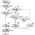
まず、駐車スペース検出処理について、図8を参照しつつ説明する。駐車スペース検出処理では、上記のように、Fソナー201、LSソナー203、Fカメラ301、LSカメラ303の情報を用いて駐車スペースPSを検出する。
First, the parking space detection process will be described with reference to FIG. In the parking space detection processing, as described above, the parking space PS is detected using the information of the F sonar 201, the LS sonar 203, the F camera 301, and the LS camera 303.
このため、メイン制御部214は、ステップS201にて、F側の検出機器に故障があるか否かを判定する。すなわち、Fソナー201およびFカメラ301の少なくとも一方に故障が発生しているか否かを判定する。そして、メイン制御部214は、F側の検出機器に故障が発生していないと判定した場合には(すなわち、ステップS201:NO)、ステップS202にてLS側の検出機器に故障が発生しているか否かを判定する。つまり、メイン制御部214は、LSソナー203およびLSカメラ303の少なくとも一方が故障しているか否かを判定する。
Therefore, in step S201, the main control unit 214 determines whether or not the F-side detection device has a failure. That is, it is determined whether or not a failure has occurred in at least one of the F sonar 201 and the F camera 301. When the main control unit 214 determines that no failure has occurred in the F-side detection device (that is, step S201: NO), a failure has occurred in the LS-side detection device in step S202. It is determined whether or not there is. That is, the main control unit 214 determines whether or not at least one of the LS sonar 203 and the LS camera 303 is out of order.
そして、メイン制御部214は、LS側の検出機器に故障が発生していないと判定した場合には(すなわち、ステップS202:NO)、ステップS203にて第1駐車スペース検出処理を実行する。つまり、メイン制御部214は、Fソナー201、LSソナー203、Fカメラ301、LSカメラ303が全て正常である場合には、第1駐車スペース検出処理を実行する。
Then, when the main control unit 214 determines that no failure has occurred in the detection device on the LS side (that is, step S202: NO), the main control part 214 executes the first parking space detection process in step S203. That is, the main control unit 214 executes the first parking space detection process when the F sonar 201, the LS sonar 203, the F camera 301, and the LS camera 303 are all normal.
なお、メイン制御部214は、ステップS202におけるLSソナー203に対する判定では、第1LSソナー203aおよび第2LSソナー203bの両方が正常である場合に故障でないと判定する。つまり、メイン制御部214は、ステップS202におけるLSソナー203に対する判定では、第1LSソナー203aおよび第2LSソナー203bの一方が故障していればLSソナー203が故障していると判定する。
Note that the main control unit 214 determines that the LS sonar 203 in step S202 is not a failure when both the first LS sonar 203a and the second LS sonar 203b are normal. That is, in the determination on the LS sonar 203 in step S202, the main control unit 214 determines that the LS sonar 203 has failed if one of the first LS sonar 203a and the second LS sonar 203b has failed.
メイン制御部214は、ステップS201にてF側の検出機器に故障が発生していると判定した場合(すなわち、ステップS201:YES)、ステップS204にて、F側の検出機器の両方が故障しているか否かを判定する。つまり、メイン制御部214は、ステップS204にてFソナー201およびFカメラ301の両方が故障しているか否かを判定する。そして、メイン制御部214は、F側の検出機器の両方が故障していないと判定した場合には(すなわち、ステップS204:NO)、ステップS205にて第1LSソナー203aおよび第2LSソナー203bの両方が故障しているか否かを判定する。
When the main control unit 214 determines in step S201 that a failure has occurred in the F-side detection device (that is, step S201: YES), in step S204 both F-side detection devices fail. Is determined. That is, the main control unit 214 determines in step S204 whether or not both the F sonar 201 and the F camera 301 are out of order. Then, when the main control unit 214 determines that both of the F-side detection devices are not in failure (that is, step S204: NO), both of the first LS sonar 203a and the second LS sonar 203b are determined in step S205. To determine whether or not there is a failure.
メイン制御部214は、第1LSソナー203aおよび第2LSソナー203bの両方が故障していないと判定した場合(すなわち、S205:NO)、ステップS206にて第2駐車スペース検出処理を実行する。つまり、メイン制御部214は、ステップS206にて第1LSソナー203aおよび第2LSソナー203bの少なくとも一方が正常であれば第2駐車スペース検出処理を実行する。
When the main control unit 214 determines that both the first LS sonar 203a and the second LS sonar 203b have not failed (that is, S205: NO), it executes the second parking space detection process in step S206. That is, the main control unit 214 executes the second parking space detection process if at least one of the first LS sonar 203a and the second LS sonar 203b is normal in step S206.
メイン制御部214は、第1LSソナー203aおよび第2LSソナー203bの両方が故障していると判定した場合(すなわち、S205:YES)、ステップS207にてLSカメラ303が故障しているか否かを判定する。メイン制御部214は、ステップS207にてLSカメラ303が故障していないと判定した場合には(すなわち、ステップS207:NO)、ステップS206にて第2駐車スペース検出処理を実行する。また、メイン制御部214は、ステップS202にて、LS側の検出機器に故障が発生していると判定した場合には(すなわち、S202:YES)、ステップS205以降の処理を実行する。
When determining that both the first LS sonar 203a and the second LS sonar 203b are out of order (that is, S205: YES), the main control unit 214 determines whether or not the LS camera 303 is out of order in step S207. To do. When determining in step S207 that the LS camera 303 has not failed (that is, step S207: NO), the main control unit 214 executes the second parking space detection process in step S206. In addition, when the main control unit 214 determines in step S202 that a failure has occurred in the detection device on the LS side (that is, S202: YES), the main control part 214 executes the processing from step S205.
ステップS206の第2駐車スペース検出処理では、Fソナー201、LSソナー203、Fカメラ301、LSカメラ303の故障状態を特定し、故障状態に基づいた処理を実行する。すなわち、ステップS206の処理を実行するのは、Fソナー201、LSソナー203、Fカメラ301、LSカメラ303の少なくとも一つに故障があり、かつ車両10の前方および左側方の状態を認識できる場合である。このため、メイン制御部214は、故障していない検出機器の情報を用いて駐車スペース検出処理を実行する。
In the second parking space detection process of step S206, the failure state of the F sonar 201, the LS sonar 203, the F camera 301, and the LS camera 303 is specified, and the process based on the failure state is executed. That is, the process of step S206 is executed when at least one of the F sonar 201, the LS sonar 203, the F camera 301, and the LS camera 303 has a failure, and the states of the front and left sides of the vehicle 10 can be recognized. Is. Therefore, the main control unit 214 executes the parking space detection process using the information of the detection device that is not in failure.
なお、第2駐車スペース検出処理では、上記図6Aを参照して説明したように、第1、第2LSソナー203a、203bが故障していてLSカメラ303が正常である場合には、白線WLが存在しないと駐車スペースPSを検出できない処理となる。また、LSカメラ303が故障していて第1、第2LSソナー203a、203bが正常である場合には、駐車車両110が駐車されていないと駐車スペースPSを検出できない処理となる。さらに、第1、第2LSソナー203a、203bの一方が故障していてLSカメラ303が正常である場合には、正常な一方のソナーとLSカメラ303を用いた第2駐車スペース検出処理となる。
In the second parking space detection process, as described with reference to FIG. 6A, when the first and second LS sonars 203a and 203b are out of order and the LS camera 303 is normal, the white line WL is If it does not exist, the parking space PS cannot be detected. When the LS camera 303 is out of order and the first and second LS sonars 203a and 203b are normal, the parking space PS cannot be detected unless the parked vehicle 110 is parked. Further, when one of the first and second LS sonars 203a and 203b is out of order and the LS camera 303 is normal, the second parking space detection process using the normal one sonar and the LS camera 303 is performed.
そして、メイン制御部214は、上記のように、第1駐車スペース検出処理または第2駐車スペース検出処理を実行して駐車スペースPSを検出した場合には、当該駐車スペースPSまでの経路を導出する。その後、メイン制御部214は、後述の角度調整処理および駐車処理では、導出した経路に従って車両10を走行させる。
When the main control unit 214 detects the parking space PS by executing the first parking space detection process or the second parking space detection process as described above, the main control unit 214 derives the route to the parking space PS. .. After that, the main control unit 214 causes the vehicle 10 to travel along the derived route in the angle adjustment process and the parking process described later.
また、メイン制御部214は、ステップS204にて、F側の検出機器の両方が故障していると判定した場合には(すなわち、ステップS204:YES)、自車両10の前方の状態を認識できない。同様に、メイン制御部214は、ステップS207にてLSカメラ303が故障していると判定した場合には(すなわち、ステップS207:YES)、自車両10の左側方の状態を認識できない。このため、メイン制御部214は、これらの場合には、ステップS208にて駐車スペース検出処理を中止する。
In addition, when the main control unit 214 determines in step S204 that both of the F-side detection devices are out of order (that is, step S204: YES), it cannot recognize the state in front of the host vehicle 10. .. Similarly, when the main control unit 214 determines in step S207 that the LS camera 303 is out of order (that is, step S207: YES), it cannot recognize the left side state of the host vehicle 10. Therefore, in these cases, the main control unit 214 cancels the parking space detection process in step S208.
そして、メイン制御部214は、ステップS203、S206、S208の処理を実行した後は、ステップS209にて、ディスプレイ41に対応する処理の画像を表示させる処理を実行させる。例えば、メイン制御部214は、ステップS203で第1駐車スペース検出処理を行う場合には、駐車スペース検出処理を正常に行っていることを報知する画像がディスプレイ41に表示されるようにする。
Then, after executing the processing of steps S203, S206, and S208, the main control unit 214 causes the processing of displaying the image of the processing corresponding to the display 41 in step S209. For example, when performing the first parking space detection process in step S203, the main control unit 214 causes the display 41 to display an image notifying that the parking space detection process is normally performed.
また、メイン制御部214は、ステップS206で第2駐車スペース検出処理を実行する場合には、故障している検出機器を報知すると共に、第2駐車スペース検出処理を実行することを報知する画像がディスプレイ41に表示されるようにする。この場合、LSソナー203が故障している場合には、白線WLが存在しない場合には駐車スペース検出処理が完了しないことも合わせて報知する。また、LSカメラ303が故障している場合には、駐車車両110が駐車されていない場合には、駐車スペース検出処理が完了しないことも報知する。さらに、第1LSソナー203aおよび第2LSソナー203bの一方が故障している場合には、故障している検出機器を報知する画像がディスプレイ41に表示されるようにする。また、メイン制御部214は、ステップS208で駐車スペース検出処理を中止する場合には、故障している検出機器を報知すると共に、駐車スペース検出処理を実行できないことを報知する画像がディスプレイ41に表示されるようにする。これにより、乗員は、駐車スペース検出処理の状態を認識できる。
In addition, when executing the second parking space detection process in step S206, the main control unit 214 notifies an image of the detection device in failure and an image notifying that the second parking space detection process is executed. Display on the display 41. In this case, if the LS sonar 203 is out of order and the white line WL does not exist, it is also notified that the parking space detection processing is not completed. Further, if the LS camera 303 is out of order and the parked vehicle 110 is not parked, the fact that the parking space detection processing is not completed is also notified. Further, when one of the first LS sonar 203a and the second LS sonar 203b is out of order, the display 41 displays an image notifying the detection device that is out of order. Further, when the parking space detection process is stopped in step S208, the main control unit 214 displays an image on the display 41 notifying the malfunctioning detection device and notifying that the parking space detection process cannot be executed. To be done. Thereby, the occupant can recognize the state of the parking space detection processing.
以上が本実施形態における駐車スペース検出処理である。そして、駐車スペース検出処理では、ステップS203、ステップS206、ステップS208の各処理が故障対応処理に相当する。なお、ステップS203は、例えば、Rソナー202等が故障していても第1駐車スペース検出処理を実行するため、故障している機器に応じた故障対応処理に含まれる。
The above is the parking space detection processing in the present embodiment. Then, in the parking space detection process, each process of step S203, step S206, and step S208 corresponds to the failure handling process. It should be noted that step S203 is included in the failure handling processing corresponding to the failed device, because the first parking space detection process is executed even if the R sonar 202 or the like has failed.
次に、角度調整処理について、図9を参照しつつ説明する。角度調整処理では、上記のように、Fソナー201、RSソナー204、Fカメラ301、RSカメラ304の情報を用いて駐車スペースPSに対する車両10の角度を調整する。
Next, the angle adjustment processing will be described with reference to FIG. In the angle adjustment processing, as described above, the angle of the vehicle 10 with respect to the parking space PS is adjusted using the information of the F sonar 201, the RS sonar 204, the F camera 301, and the RS camera 304.
このため、メイン制御部214は、ステップS301にて、ステップS201と同様に、F側の検出機器に故障が発生しているか否かを判定する。そして、メイン制御部214は、F側の検出機器に故障が発生していないと判定した場合には(すなわち、ステップS301:NO)、ステップS302にてRS側の検出機器に故障が発生しているか否かを判定する。つまり、メイン制御部214は、RSソナー204およびRSカメラ304の少なくとも一方が故障しているか否かを判定する。
Therefore, in step S301, the main control unit 214 determines whether or not a failure has occurred in the F-side detection device, as in step S201. When the main control unit 214 determines that no failure has occurred in the F-side detection device (that is, step S301: NO), a failure has occurred in the RS-side detection device in step S302. It is determined whether or not there is. That is, the main control unit 214 determines whether or not at least one of the RS sonar 204 and the RS camera 304 is out of order.
そして、メイン制御部214は、RS側の検出機器に故障が発生していないと判定した場合には(すなわち、ステップS302:NO)、ステップS303にて第1角度調整処理を実行する。すなわち、メイン制御部214は、Fソナー201およびRSソナー204の検出信号と、Fカメラ301およびRSカメラ304の画像信号に基づいて角度調整処理を実行する。
Then, when the main control unit 214 determines that no failure has occurred in the detection device on the RS side (that is, step S302: NO), the main control unit 214 executes the first angle adjustment process in step S303. That is, the main control unit 214 executes the angle adjustment processing based on the detection signals of the F sonar 201 and the RS sonar 204 and the image signals of the F camera 301 and the RS camera 304.
なお、メイン制御部214は、ステップS302におけるRSソナー204に対する判定では、第1RSソナー204aおよび第2RSソナー204bの両方が正常である場合に故障でないと判定する。つまり、メイン制御部214は、ステップS302におけるRSソナー204に対する判定では、第1RSソナー204aおよび第2RSソナー204bの一方が故障していればRSソナー204が故障していると判定する。
Note that the main control unit 214 determines that the RS sonar 204 in step S302 is not a failure when both the first RS sonar 204a and the second RS sonar 204b are normal. That is, in the determination on the RS sonar 204 in step S302, the main control unit 214 determines that the RS sonar 204 is out of order if one of the first RS sonar 204a and the second RS sonar 204b is out of order.
メイン制御部214は、ステップS301にてF側の検出機器に故障が発生していると判定した場合(すなわち、ステップS301:YES)、ステップS304にて、ステップS204と同様に、F側の検出機器の両方が故障しているか否かを判定する。そして、メイン制御部214は、F側の検出機器の両方が故障していないと判定した場合には(すなわち、ステップS304:NO)、ステップS305にて第1RSソナー204aおよび第2RSソナー204bの両方が故障しているか否かを判定する。
When the main control unit 214 determines in step S301 that a failure has occurred in the F-side detection device (that is, step S301: YES), in step S304, similarly to step S204, F-side detection is performed. Determine if both devices are faulty. When the main control unit 214 determines that both of the F-side detection devices are not in failure (that is, step S304: NO), both of the first RS sonar 204a and the second RS sonar 204b are determined in step S305. It is determined whether or not there is a failure.
メイン制御部214は、第1RSソナー204aおよび第2RSソナー204bの両方が故障していないと判定した場合(すなわち、S305:NO)、ステップS306にて第2角度調整処理を実行する。つまり、メイン制御部214は、ステップS306にて第1RSソナー204aおよび第2RSソナー204bの少なくとも一方が正常であれば第2角度調整処理を実行する。
When the main control unit 214 determines that both the first RS sonar 204a and the second RS sonar 204b have not failed (that is, S305: NO), it executes the second angle adjustment processing in step S306. That is, the main control unit 214 executes the second angle adjustment processing if at least one of the first RS sonar 204a and the second RS sonar 204b is normal in step S306.
メイン制御部214は、第1RSソナー204aおよび第2RSソナー204bの両方が故障していると判定した場合(すなわち、S305:YES)、ステップS307にてRSカメラ304が故障しているか否かを判定する。メイン制御部214は、ステップS307にてRSカメラ304が故障していないと判定した場合には(すなわち、ステップS307:NO)、ステップS306にて第2角度調整処理を実行する。また、メイン制御部214は、ステップS302にて、RS側の検出機器に故障が発生していると判定した場合には(すなわち、S302:YES)、ステップS305以降の処理を実行する。
When determining that both the first RS sonar 204a and the second RS sonar 204b are out of order (that is, S305: YES), the main control unit 214 determines in step S307 whether or not the RS camera 304 is out of order. To do. When determining in step S307 that the RS camera 304 has not failed (that is, step S307: NO), the main controller 214 executes the second angle adjustment processing in step S306. In addition, when the main control unit 214 determines in step S302 that a failure has occurred in the RS-side detection device (that is, S302: YES), the main control part 214 executes the processes of step S305 and subsequent steps.
ステップS306の第2角度調整処理では、Fソナー201、RSソナー204、Fカメラ301、RSカメラ304の故障状態を特定し、故障状態に基づいた処理を実行する。すなわち、ステップS306の処理を実行するのは、Fソナー201、RSソナー204、Fカメラ301、RSカメラ304の少なくとも一つに故障があり、かつ車両10の前方および右側方の状態を認識できる場合である。このため、メイン制御部214は、故障していない検出機器の情報を用いて角度調整処理を実行する。
In the second angle adjustment processing of step S306, the failure state of the F sonar 201, RS sonar 204, F camera 301, RS camera 304 is specified, and processing based on the failure state is executed. That is, the process of step S306 is executed when at least one of the F sonar 201, the RS sonar 204, the F camera 301, and the RS camera 304 has a failure, and the states of the front and right sides of the vehicle 10 can be recognized. Is. For this reason, the main control unit 214 executes the angle adjustment process using the information of the detection device that has not failed.
また、メイン制御部214は、ステップS304にてF側の検出機器の両方が故障していると判定した場合には(すなわち、ステップS304:YES)、自車両10の前方の状態を認識できない。同様に、メイン制御部214は、ステップS307にてRSカメラ304が故障していると判定した場合には(すなわち、ステップS307:YES)、自車両10の右側方の状態を認識できない。このため、メイン制御部214は、これらの場合には、ステップS308にて角度調整処理を中止する。
Further, when the main control unit 214 determines in step S304 that both of the F-side detection devices have failed (that is, step S304: YES), it cannot recognize the state in front of the host vehicle 10. Similarly, when the main control unit 214 determines that the RS camera 304 is out of order in step S307 (that is, step S307: YES), it cannot recognize the right side state of the host vehicle 10. Therefore, in these cases, the main control unit 214 cancels the angle adjustment processing in step S308.
そして、メイン制御部214は、ステップS303、S306、S308の処理を実行した後は、ステップS309にて、ディスプレイ41に対応する処理の画像を表示させる処理を実行させる。例えば、メイン制御部214は、ステップS303で第1角度調整処理を行う場合には、角度調整処理を正常に行っていることを報知する画像がディスプレイ41に表示されるようにする。
Then, after executing the processes of steps S303, S306, and S308, the main control unit 214 causes the process of displaying the image of the process corresponding to the display 41 in step S309. For example, when the first angle adjustment process is performed in step S303, the main control unit 214 causes the display 41 to display an image notifying that the angle adjustment process is normally performed.
また、メイン制御部214は、ステップS306で第2角度調整処理を実行する場合には、故障している検出機器を報知すると共に、第2角度調整処理を実行することを報知する画像がディスプレイ41に表示されるようにする。
Further, when executing the second angle adjustment processing in step S306, the main control unit 214 notifies the failure detection device and displays an image notifying that the second angle adjustment processing is executed on the display 41. To be displayed in.
さらに、メイン制御部214は、ステップS308で角度調整処理を中止する場合には、故障している検出機器を報知すると共に、角度調整処理を実行できないことを報知する画像がディスプレイ41に表示されるようにする。
Further, when stopping the angle adjustment process in step S308, the main control unit 214 notifies the failure detection device and displays an image notifying that the angle adjustment process cannot be performed on the display 41. To do so.
以上が本実施形態における角度調整処理である。そして、角度調整処理では、ステップS303、ステップS306、ステップS308の各処理が故障対応処理に相当する。なお、ステップS303は、例えば、Rソナー202等が故障していても第1角度調整処理を実行するため、故障している機器に応じた故障対応処理に含まれる。
The above is the angle adjustment processing in the present embodiment. Then, in the angle adjustment processing, each processing of step S303, step S306, and step S308 corresponds to the failure handling processing. It should be noted that step S303 is included in the failure handling processing corresponding to the failed device because the first angle adjustment processing is executed even if the R sonar 202 or the like has failed.
次に、駐車処理について、図10を参照しつつ説明する。駐車処理では、上記のように、Rソナー202、RSソナー204、Rカメラ302、RSカメラ304の情報を用いて駐車スペースPSに車両10を駐車する。
Next, the parking process will be described with reference to FIG. In the parking process, as described above, the vehicle 10 is parked in the parking space PS using the information of the R sonar 202, the RS sonar 204, the R camera 302, and the RS camera 304.
このため、メイン制御部214は、ステップS401にて、まず、R側の検出機器に故障が発生しているか否かを判定する。すなわち、Rソナー202およびRカメラ302の少なくとも一方が故障しているか否かを判定する。そして、メイン制御部214は、R側の検出機器に故障が発生していないと判定した場合には(すなわち、ステップS401:NO)、ステップS402にて、ステップS302と同様に、RS側の検出機器に故障があるか否かを判定する。メイン制御部214は、RS側の検出機器に故障が発生していないと判定した場合には(すなわち、ステップS402:NO)、ステップS403にて第1駐車処理を実行する。すなわち、メイン制御部214は、Rソナー202およびRSソナー204の検出信号と、Rカメラ302およびRSカメラ304の画像信号に基づいて駐車処理を実行する。
Therefore, in step S401, the main control unit 214 first determines whether or not a failure has occurred in the detection device on the R side. That is, it is determined whether or not at least one of the R sonar 202 and the R camera 302 is out of order. When the main control unit 214 determines that no failure has occurred in the R-side detection device (that is, step S401: NO), in step S402, the RS-side detection is performed as in step S302. Determine if the device is defective. When determining that no failure has occurred in the RS-side detection device (that is, step S402: NO), the main control unit 214 executes the first parking process in step S403. That is, the main control unit 214 executes the parking process based on the detection signals of the R sonar 202 and the RS sonar 204 and the image signals of the R camera 302 and the RS camera 304.
なお、メイン制御部214は、ステップS402におけるRSソナー204に対する判定では、ステップS302と同様に、第1RSソナー204aおよび第2RSソナー204bの両方が正常である場合に故障でないと判定する
Note that, in the determination on the RS sonar 204 in step S402, the main control unit 214 determines that there is no failure when both the first RS sonar 204a and the second RS sonar 204b are normal, as in step S302.
メイン制御部214は、ステップS401にてR側の検出機器に故障が発生していると判定した場合(すなわち、ステップS401:YES)、ステップS404にて、R側の検出機器の両方が故障しているか否かを判定する。そして、メイン制御部214は、R側の検出機器の両方が故障していないと判定した場合には(すなわち、ステップS404:NO)、ステップS405にて第1RSソナー204aおよび第2RSソナー204bの両方が故障しているか否かを判定する。
When the main control unit 214 determines in step S401 that a failure has occurred in the R-side detection device (that is, step S401: YES), in step S404 both R-side detection devices fail. Is determined. When the main control unit 214 determines that both the R-side detection devices are not in failure (that is, step S404: NO), both the first RS sonar 204a and the second RS sonar 204b are determined in step S405. It is determined whether or not there is a failure.
メイン制御部214は、第1RSソナー204aおよび第2RSソナー204bの両方が故障していないと判定した場合(すなわち、ステップS405:NO)、ステップS406にて第2駐車処理を実行する。つまり、メイン制御部214は、ステップS406にて第1RSソナー204aおよび第2RSソナー204bの少なくとも一方が正常であれば第2駐車処理を実行する。
When the main control unit 214 determines that both the first RS sonar 204a and the second RS sonar 204b are not in failure (that is, step S405: NO), the main controller 214 executes the second parking process in step S406. That is, the main control unit 214 executes the second parking process if at least one of the first RS sonar 204a and the second RS sonar 204b is normal in step S406.
メイン制御部214は、第1RSソナー204aおよび第2RSソナー204bの両方が故障していると判定した場合(すなわち、S405:YES)、ステップS407にてRSカメラ304が故障しているか否かを判定する。メイン制御部214は、ステップS407にてRSカメラ304が故障していないと判定した場合には(すなわち、ステップS407:NO)、ステップS406にて第2駐車処理を実行する。また、メイン制御部214は、ステップS402にて、RS側の検出機器に故障が発生していると判定した場合には(すなわち、S402:YES)、ステップS405以降の処理を実行する。
When determining that both the first RS sonar 204a and the second RS sonar 204b are out of order (that is, S405: YES), the main controller 214 determines in step S407 whether or not the RS camera 304 is out of order. To do. When determining in step S407 that the RS camera 304 has not failed (that is, step S407: NO), the main control unit 214 executes the second parking process in step S406. In addition, when the main control unit 214 determines in step S402 that a failure has occurred in the RS-side detection device (that is, S402: YES), the main control unit 214 executes the processing from step S405.
ステップS406の第2駐車処理では、Rソナー202、RSソナー204、Rカメラ302、RSカメラ304の故障状態を特定し、故障状態に基づいた処理を実行する。すなわち、ステップS406の処理を実行するのは、Rソナー202、RSソナー204、Rカメラ302、RSカメラ304の少なくとも一つに故障があり、かつ車両10の後方および右側方の状態を認識できる場合である。このため、メイン制御部214は、故障していない検出機器の情報を用いて駐車スペース検出処理を実行する。
In the second parking process of step S406, the failure state of the R sonar 202, the RS sonar 204, the R camera 302, and the RS camera 304 is specified, and the processing based on the failure state is executed. That is, the processing of step S406 is executed when at least one of the R sonar 202, the RS sonar 204, the R camera 302, and the RS camera 304 has a failure, and the rear and right sides of the vehicle 10 can be recognized. Is. Therefore, the main control unit 214 executes the parking space detection process using the information of the detection device that is not in failure.
また、メイン制御部214は、ステップS404にてR側の検出機器の両方が故障していると判定した場合(すなわち、ステップS404:YES)には、自車両10の後方の状態を認識できない。同様に、メイン制御部214は、ステップS407にてRSカメラ304が故障していると判定した場合(すなわち、ステップS407:YES)には、自車両10の右側方の状態を認識できない。このため、メイン制御部214は、ステップS408にて駐車処理を中止する。
Further, when the main control unit 214 determines in step S404 that both of the R-side detection devices have failed (that is, step S404: YES), it cannot recognize the state behind the vehicle 10. Similarly, when the main control unit 214 determines in step S407 that the RS camera 304 is out of order (that is, step S407: YES), it cannot recognize the right side state of the host vehicle 10. Therefore, the main control unit 214 stops the parking process in step S408.
そして、メイン制御部214は、ステップS403、S406、S408の処理を実行した後は、ステップS409にて、ディスプレイ41に対応する処理の画像を表示させる処理を実行する。例えば、メイン制御部214は、ステップS403で第1駐車処理を行う場合には、駐車処理を正常に行っていることを報知する画像がディスプレイ41に表示されるようにする。
Then, after executing the processes of steps S403, S406, and S408, the main control unit 214 executes the process of displaying the image of the process corresponding to the display 41 in step S409. For example, when performing the first parking process in step S403, the main control unit 214 causes the display 41 to display an image notifying that the parking process is normally performed.
また、メイン制御部214は、ステップS406で第2駐車処理を実行する場合には、故障している検出機器を報知すると共に、第2駐車処理を実行することを報知する画像がディスプレイ41に表示されるようにする。
Further, when executing the second parking process in step S406, the main control unit 214 displays an image on the display 41 notifying the faulty detection device and also executing the second parking process. To be done.
さらに、メイン制御部214は、ステップS408で駐車処理を中止する場合には、故障している検出機器を報知すると共に、駐車処理を実行できないことを報知する画像がディスプレイ41に表示されるようにする。
Further, when stopping the parking process in step S408, the main control unit 214 notifies the detection device that is out of order and displays an image notifying that the parking process cannot be executed on the display 41. To do.
以上が本実施形態における駐車処理である。そして、駐車処理では、ステップS403、ステップS406、ステップS408の各処理が故障対応処理に相当する。なお、ステップS403は、例えば、Fソナー201等が故障していても第1駐車処理を実行するため、故障している機器に応じた故障対応処理に含まれる。
The above is the parking process in the present embodiment. Then, in the parking process, each process of step S403, step S406, and step S408 corresponds to the failure handling process. It should be noted that step S403 is included in the failure handling processing corresponding to the failed device, because the first parking process is executed even if the F sonar 201 or the like has failed.
自動駐車処理の説明に戻り、図7に示されるように、メイン制御部214は、ステップS105の駐車スペース検出処理、ステップS107の角度調整処理、またはステップS108の駐車処理を実行した後は、ステップS109の判定処理を行う。メイン制御部214は、ステップS109では、中止処理が実行されたか、または自動駐車処理が終了したか否かを判定する。そして、メイン制御部214は、処理が中止されておらず、自動駐車処理も終了していないと判定した場合には(すなわち、ステップS109:NO)、ステップS101以降の処理を繰り返す。これに対し、メイン制御部214は、処理が中止された、または自動駐車処理が終了したと判定した場合には(すなわち、ステップS109:YES)、自動駐車処理を終了する。
Returning to the description of the automatic parking process, as shown in FIG. 7, the main control unit 214 executes the parking space detection process of step S105, the angle adjustment process of step S107, or the parking process of step S108, and then, The determination process of S109 is performed. In step S109, the main control unit 214 determines whether or not the cancellation processing has been executed or the automatic parking processing has ended. When the main control unit 214 determines that the processing has not been stopped and the automatic parking processing has not ended (that is, step S109: NO), the processing from step S101 onward is repeated. On the other hand, when the main control unit 214 determines that the process is stopped or the automatic parking process is completed (that is, step S109: YES), the main control unit 214 ends the automatic parking process.
以上説明したように、本実施形態では、自動駐車処理を行う場合、各処理で用いられるソナー201~204およびカメラ301~304の故障状態に基づいた処理を行う。すなわち、メイン制御部214は、駐車スペース検出処理を実行する上記図5Aの例では、Fソナー201およびFカメラ301の故障状態、およびLSソナー203およびLSカメラ303の故障状態に基づいて駐車スペース検出処理を実行する。また、メイン制御部214は、角度調整処理を実行する上記図5Bの例では、Fソナー201およびFカメラ301の故障状態、およびRSソナー204およびRSカメラ304の故障状態に基づいて角度調整処理を実行する。メイン制御部214は、駐車処理を実行する上記図5Cの例では、Rソナー202およびRカメラ302の故障状態、およびRSソナー204およびRSカメラ304の故障状態に基づいて駐車スペース検出処理を実行する。
As described above, in the present embodiment, when performing the automatic parking process, the process based on the failure state of the sonars 201 to 204 and the cameras 301 to 304 used in each process is performed. That is, in the example of FIG. 5A that executes the parking space detection process, the main control unit 214 detects the parking space based on the failure states of the F sonar 201 and the F camera 301 and the failure states of the LS sonar 203 and the LS camera 303. Execute the process. Further, in the example of FIG. 5B that executes the angle adjustment processing, the main control unit 214 performs the angle adjustment processing based on the failure states of the F sonar 201 and F camera 301 and the failure states of the RS sonar 204 and RS camera 304. Run. In the example of FIG. 5C that executes the parking process, the main control unit 214 executes the parking space detection process based on the failure states of the R sonar 202 and the R camera 302 and the failure states of the RS sonar 204 and the RS camera 304. ..
そして、メイン制御部214は、各処理で必要な情報を取得する検出機器が故障している場合には、各第2処理または中止処理を実行する。言い換えると、メイン制御部214は、各処理で必要でない情報を取得する検出機器が故障していたとしても、そのまま各処理を継続する。このため、例えば、駐車処理を実行する際にFソナー201が故障したとしてもそのまま駐車処理を実行する。したがって、乗員は、自動駐車処理を有効に利用できる。
Then, the main control unit 214 executes each of the second processing or the cancellation processing when the detection device that acquires the information necessary for each processing is out of order. In other words, the main control unit 214 continues each process as it is, even if the detection device that acquires information that is not necessary in each process is out of order. Therefore, for example, even if the F-sonar 201 fails during the parking process, the parking process is executed as it is. Therefore, the occupant can effectively use the automatic parking process.
さらに、メイン制御部214は、各処理で必要な情報を取得する検出機器の一部が故障していたとしても、各処理を継続することがあるようにしている。例えば、駐車スペース検出処理の場合、Fソナー201およびFカメラ301の一方が故障していても、LSソナー203およびLSカメラ303の少なくとも一方が正常であれば、第2駐車スペース検出処理を実行する。このため、乗員は、自動駐車処理を有効に活用できる。
Furthermore, the main control unit 214 may continue each process even if a part of the detection device that acquires information necessary for each process is out of order. For example, in the case of the parking space detection process, the second parking space detection process is executed if at least one of the LS sonar 203 and the LS camera 303 is normal even if one of the F sonar 201 and the F camera 301 is out of order. .. Therefore, the occupant can effectively utilize the automatic parking process.
また、本実施形態では、LSソナー203は、第1LSソナー203aおよび第2LSソナー203bが互いに独立している。そして、メイン制御部214は、第1LSソナー203aおよび第2LSソナー203bの一方のソナーが故障していたとしても、他方のソナーからの検出信号を用いて各第2処理を実行する。同様に、RSソナー204は、第1RSソナー204aおよび第2RSソナー204bが互いに独立している。そして、メイン制御部214は、第1RSソナー204aおよび第2RSソナー204bの一方のソナーが故障していたとしても、他方のソナーからの検出信号を用いて各第2処理を実行する。したがって、乗員は、自動駐車処理を有効に利用できる。
Further, in the present embodiment, in the LS sonar 203, the first LS sonar 203a and the second LS sonar 203b are independent of each other. Then, even if one sonar of the first LS sonar 203a and the second LS sonar 203b is out of order, the main control unit 214 executes each second process using the detection signal from the other sonar. Similarly, in the RS sonar 204, the first RS sonar 204a and the second RS sonar 204b are independent of each other. Then, even if one of the first RS sonar 204a and the second RS sonar 204b is out of order, the main controller 214 executes each second process using the detection signal from the other sonar. Therefore, the occupant can effectively use the automatic parking process.
(第2実施形態)
第2実施形態について説明する。本実施形態は、第1実施形態に対し、駐車スペース検出処理および角度調整処理を変更したものである。その他に関しては、第1実施形態と同様であるため、ここでは説明を省略する。 (Second embodiment)
The second embodiment will be described. The present embodiment differs from the first embodiment in that parking space detection processing and angle adjustment processing are changed. Since the other points are the same as those in the first embodiment, description thereof will be omitted here.
まず、本実施形態の駐車スペース検出処理について、図11を参照しつつ説明する。
First, the parking space detection processing of this embodiment will be described with reference to FIG.
駐車スペース検出処理では、メイン制御部214は、ステップS210にて、駐車処理の際に使用されるR側の検出機器の両方が故障しているか否かを判定する。つまり、メイン制御部214は、Rソナー202およびRカメラ302の両方が故障しているか否かを判定する。そして、メイン制御部214は、ステップS210にて、R側の検出機器の両方が故障していないと判定した場合には(すなわち、ステップS210:NO)、ステップS211を実行する。メイン制御部214は、ステップS211では、駐車処理および角度調整処理の際に使用されるRS側の検出機器の両方が故障しているか否かを判定する。つまり、メイン制御部214は、RSソナー204およびRSカメラ304の両方が故障しているか否かを判定する。メイン制御部214は、RS側の検出機器の両方が故障していないと判定した場合には(S211:NO)、ステップS201以降の処理を順に実行する。
In the parking space detection process, in step S210, the main control unit 214 determines whether or not both the R-side detection devices used in the parking process are out of order. That is, the main control unit 214 determines whether or not both the R sonar 202 and the R camera 302 are out of order. Then, when the main control unit 214 determines in step S210 that neither of the R-side detection devices has failed (that is, step S210: NO), the main control part 214 executes step S211. In step S211, the main control unit 214 determines whether or not both of the RS-side detection devices used in the parking process and the angle adjustment process have a failure. That is, the main control unit 214 determines whether or not both the RS sonar 204 and the RS camera 304 are out of order. When the main control unit 214 determines that both the detection devices on the RS side are not in failure (S211: NO), the main control unit 214 sequentially executes the processes from step S201.
なお、ステップS210におけるRS側の検出機器の両方が故障しているとは、RSソナー204およびRSカメラ304が故障している場合であり、メイン制御部214が右側方の状態を認識できない場合である。つまり、ここのでRSソナー204の故障とは、第1RSソナー204aおよび第2RSソナー204bの両方が故障している場合のことである。
It should be noted that both of the detection devices on the RS side in step S210 are defective when the RS sonar 204 and the RS camera 304 are defective and the main control unit 214 cannot recognize the state on the right side. is there. That is, here, the failure of the RS sonar 204 is a case where both the first RS sonar 204a and the second RS sonar 204b have a failure.
メイン制御部214は、ステップS210にて、R側の検出機器の両方が故障していると判定した場合には(すなわち、ステップS210:YES)、ステップS208にて駐車スペース検出処理を中止する。また、メイン制御部214は、ステップS211にて、RS側の検出機器の両方が故障していると判定した場合には(すなわち、ステップS211:YES)、ステップS208にて駐車スペース検出処理を中止する。
When the main control unit 214 determines in step S210 that both of the R-side detection devices are out of order (that is, step S210: YES), the main control part 214 stops the parking space detection process in step S208. In addition, when the main control unit 214 determines in step S211 that both of the RS-side detection devices are out of order (that is, step S211: YES), the main control part 214 stops the parking space detection process in step S208. To do.
すなわち、本実施形態では、駐車スペース検出処理を行う際、後の角度調整処理および駐車処理にて中止処理が実行される場合には、駐車スペース検出処理を終了することにより、ステップS109にて自動駐車処理が終了するようにする。
That is, in the present embodiment, when the parking space detection process is performed, if the cancellation process is executed in the subsequent angle adjustment process and the parking process, the parking space detection process is terminated, and the automatic process is performed in step S109. Allow the parking process to end.
続いて、本実施形態の角度調整処理について、図12を参照しつつ説明する。
Next, the angle adjustment processing of this embodiment will be described with reference to FIG.
角度調整処理では、メイン制御部214は、ステップS310にて、ステップS210と同様に、駐車処理の際に使用されるR側の検出機器の両方が故障しているか否かを判定する。そして、メイン制御部214は、ステップS310にて、R側の検出機器の両方が故障していないと判定した場合には(すなわち、ステップS310:NO)、ステップS301以降の処理を順に実行する。
In the angle adjustment processing, in step S310, the main control unit 214 determines whether or not both the R-side detection devices used in the parking processing have a failure, as in step S210. When the main control unit 214 determines in step S310 that neither of the R-side detection devices is out of order (that is, step S310: NO), the main control part 214 sequentially executes the processing from step S301.
一方、メイン制御部214は、ステップS310にて、R側の検出機器の故障が発生していると判定した場合には(すなわち、ステップS310:YES)、ステップS308にて角度調整処理を中止する。
On the other hand, when the main control unit 214 determines in step S310 that a failure has occurred in the R-side detection device (that is, step S310: YES), it cancels the angle adjustment processing in step S308. ..
すなわち、角度調整処理では、上記駐車スペース検出処理と同様に、後の駐車処理にて中止処理が実行される場合には、角度調整処理を終了することにより、ステップS109にて自動駐車処理が終了されるようにする。
That is, in the angle adjustment processing, similarly to the parking space detection processing, when the cancellation processing is executed in the subsequent parking processing, the angle adjustment processing is ended, and the automatic parking processing is ended in step S109. To be done.
以上説明したように、本実施形態では、自動駐車処理を行う場合、後の処理で使用される検出機器が故障している場合には、当該後の処理を実行する前に自動駐車処理を中止する。このため、自動駐車処理が途中で終了し難くなり、乗員に煩わしさや不快感を与えることを抑制できる。
As described above, in the present embodiment, when the automatic parking process is performed, if the detection device used in the subsequent process is out of order, the automatic parking process is stopped before the subsequent process is executed. To do. For this reason, it becomes difficult for the automatic parking process to end halfway, and it is possible to prevent the passenger from being bothered and uncomfortable.
(他の実施形態)
本開示は、実施形態に準拠して記述されたが、本開示は当該実施形態や構造に限定されるものではないと理解される。本開示は、様々な変形例や均等範囲内の変形をも包含する。加えて、様々な組み合わせや形態、さらには、それらに一要素のみ、それ以上、あるいはそれ以下、を含む他の組み合わせや形態をも、本開示の範疇や思想範囲に入るものである。 (Other embodiments)
Although the present disclosure has been described in accordance with the embodiments, it is understood that the present disclosure is not limited to the embodiments and the structure. The present disclosure also includes various modifications and modifications within an equivalent range. In addition, various combinations and forms, and other combinations and forms including only one element, more, or less than those, also fall within the scope and spirit of the present disclosure.
例えば、上記各実施形態において、障害物検出部20は、各ソナー201~204の代わりに、光を用いて障害物を検出する測距センサ等を有する構成とされていてもよい。また、画像取得部30は、各カメラ301~304の代わりに、画像認識センサ等を有する構成とされていてもよい。
For example, in each of the above embodiments, the obstacle detection unit 20 may be configured to have a distance measuring sensor or the like that detects an obstacle using light instead of each of the sonars 201 to 204. Further, the image acquisition unit 30 may be configured to have an image recognition sensor or the like instead of the cameras 301 to 304.
また、上記各実施形態において、メイン制御部214は、ソナー制御部213と一体化されていてもよい。そして、メイン制御部214は、ソナーECU210ではなく、カメラECU310に備えられていてもよい。さらに、メイン制御部214は、図13に示されるように、ソナーECU210やカメラECU310とは別に備えられ、自車両10の走行等に関する全体の制御を実行する統合ECU120に備えられていてもよい。
Further, in each of the above embodiments, the main control unit 214 may be integrated with the sonar control unit 213. The main control unit 214 may be provided in the camera ECU 310 instead of the sonar ECU 210. Further, as shown in FIG. 13, the main control unit 214 may be provided separately from the sonar ECU 210 and the camera ECU 310, and may be provided in the integrated ECU 120 that executes the overall control of the traveling of the vehicle 10.
そして、上記各実施形態において、各ソナー201~204および各カメラ301~304の故障判定は、メイン制御部214にて行うようにしてもよい。
In each of the above-described embodiments, the main controller 214 may determine whether each of the sonars 201 to 204 and each of the cameras 301 to 304 has a failure.
さらに、上記各実施形態において、自動駐車処理では、駐車スペースPSを検出した際の自車両10の位置によっては、角度調整処理を実行しないようにしてもよい。すなわち、駐車スペース検出処理を実行した後にそのまま駐車処理を実行できる場合には、角度調整処理を実行しないようにしてもよい。
Furthermore, in each of the above embodiments, the angle adjustment process may not be executed in the automatic parking process depending on the position of the vehicle 10 when the parking space PS is detected. That is, if the parking process can be directly executed after the parking space detection process is executed, the angle adjustment process may not be executed.
また、上記各実施形態において、駐車スペース検出処理では、当該駐車スペース検出処理を開始する前の所定期間の情報に基づいても駐車スペース検出処理を実行するようにしてもよい。そして、メイン制御部214は、処理を開始する前の情報に基づいて駐車スペースPSを検出できた場合には、そのまま角度調整処理を行うようにしてもよい。
Further, in each of the above-described embodiments, the parking space detection process may be executed based on the information of a predetermined period before the parking space detection process is started. Then, when the parking space PS can be detected based on the information before the processing is started, the main control unit 214 may directly perform the angle adjustment processing.
さらに、上記各実施形態において、Fソナー201は、第1~第4Fソナー201a~201dが一体化されておらず、互いに独立していてもよい。この場合は、Fソナー201においても、一部故障という状態が発生し得る。同様に、Rソナー202は、第1~第4Rソナー202a~202dが一体化されておらず、互いに独立してもよい。
Furthermore, in each of the above-described embodiments, the F sonar 201 may not be integrated with the first to fourth F sonars 201a to 201d and may be independent from each other. In this case, even in the F sonar 201, a state of partial failure may occur. Similarly, in the R sonar 202, the first to fourth R sonars 202a to 202d are not integrated and may be independent from each other.
また、上記各実施形態において、LSソナー203は、第1LSソナー203aと第2LSソナー203bとが一体化されていてもよい。この場合は、LSソナー203は、第1LSソナー203aおよび第2LSソナー203bの一方が故障している場合には、全体として故障していると判定される。同様に、RSソナー204は、第1RSソナー204aと第2RSソナー204bとが一体化されていてもよい。
Further, in each of the above-described embodiments, the LS sonar 203 may be integrated with the first LS sonar 203a and the second LS sonar 203b. In this case, if one of the first LS sonar 203a and the second LS sonar 203b is out of order, the LS sonar 203 is determined to be out of order as a whole. Similarly, in the RS sonar 204, the first RS sonar 204a and the second RS sonar 204b may be integrated.
さらに、上記各実施形態において、Fソナー201およびRソナー202を構成するソナーの数は4個に限定されるものではなく、適宜変更可能である。同様に、LSソナー203およびRSソナー204を構成するソナーの数は2個に限定されるものではなく、適宜変更可能である。
Furthermore, in each of the above-described embodiments, the number of sonars forming the F sonar 201 and the R sonar 202 is not limited to four, and can be changed as appropriate. Similarly, the number of sonars forming the LS sonar 203 and the RS sonar 204 is not limited to two and can be changed as appropriate.
また、上記各実施形態において、各第2処理を行う場合の具体的な処理内容は、適宜変更可能であり、駐車支援装置1が搭載される車種に応じて変化させたり、乗員が選択できるようにしてもよい。
Further, in each of the above-described embodiments, the specific processing content when performing each second processing can be changed as appropriate, and can be changed or selected by the occupant according to the vehicle type in which the parking assistance device 1 is mounted. You can
例えば、メイン制御部214は、ステップS206にて第2駐車スペース検出処理を実行する場合、当該駐車スペース検出処理を行った後の次回の駐車スペース検出処理を実行しないという判定をするようにしてもよい。同様に、ステップS306にて第2角度調整処理を実行する場合、当該角度調整処理を行った後の次回の角度調整処理を実行しないと判定するようにしてもよい。また、ステップS406にて第2駐車処理を実行する場合、当該駐車処理を行った後の次回の駐車処理を実行しないと判定するようにしてもよい。この場合、次回の自動駐車処理を全体として実行しないようにしてもよい。つまり、例えば、駐車処理にて次回の駐車処理を実行しないとするようにした場合には、次回の駐車スペース検出処理および角度調整処理も実行しないようにしてもよい。
For example, when executing the second parking space detection process in step S206, the main control unit 214 may determine not to execute the next parking space detection process after performing the parking space detection process. Good. Similarly, when the second angle adjustment process is executed in step S306, it may be determined that the next angle adjustment process after the angle adjustment process is not executed. In addition, when the second parking process is executed in step S406, it may be determined that the next parking process after the parking process is not executed. In this case, the next automatic parking process may not be executed as a whole. That is, for example, if the next parking process is not executed in the parking process, the next parking space detection process and the angle adjustment process may not be executed.
さらに、メイン制御部214は、各第2処理を実行する場合、緊急ブレーキ制御が実行不可となるように構成されていてもよい。例えば、第2駐車スペース検出処理を実行する際、Fソナー201およびFカメラ301の一方が故障している場合には、Fソナー201およびFカメラ301が正常である場合と比較して、車両10の前方の状態を認識する精度が低下する。このため、このような場合には、車両10の前方の状態を誤認する可能性がある。この場合、誤認した状態で緊急ブレーキが頻繁に作動することにより、乗員が煩わしさを感じてしまう可能性がある。したがって、各第2処理を実行する場合には、メイン制御部214は、緊急ブレーキ制御を実行しないようにしてもよい。但し、メイン制御部214は、緊急ブレーキ制御を実行しない場合には、ディスプレイ41に緊急ブレーキ制御を実行しないことを報知する等、乗員の注意力を向上させる処理を行うことが好ましい。
Further, the main control unit 214 may be configured such that the emergency brake control is disabled when executing each second process. For example, when one of the F sonar 201 and the F camera 301 is out of order when the second parking space detection process is executed, the vehicle 10 is compared with the case where the F sonar 201 and the F camera 301 are normal. The accuracy of recognizing the state in front of is reduced. Therefore, in such a case, the state in front of the vehicle 10 may be mistakenly recognized. In this case, the occupant may feel annoyed because the emergency brake frequently operates in a falsely recognized state. Therefore, when executing each second process, the main control unit 214 may not execute the emergency brake control. However, when the emergency braking control is not executed, the main control unit 214 preferably performs a process of improving the occupant's attention such as notifying the display 41 that the emergency braking control is not executed.
さらに、上記各実施形態において、ソナー部200とカメラ部300との間に精度の差がある場合には、一方が故障していても各第1処理を行うようにしてもよい。例えば、駐車スペース検出処理では、Fソナー201の方がFカメラ301より精度が高いのであれば、LSソナー203およびLSカメラ303が正常である場合には、次のようにしてもよい。すなわち、メイン制御部214は、Fソナー201が正常であればFカメラ301が故障していても第1駐車スペース検出処理を行い、Fソナー201が故障してFカメラ301が正常である場合に第2駐車スペース検出処理を実行するようにしてもよい。
Further, in each of the above-described embodiments, when there is a difference in accuracy between the sonar unit 200 and the camera unit 300, each first process may be performed even if one of them is out of order. For example, in the parking space detection process, if the F sonar 201 has higher accuracy than the F camera 301, and the LS sonar 203 and the LS camera 303 are normal, the following may be performed. That is, if the F sonar 201 is normal, the main control unit 214 performs the first parking space detection process even if the F camera 301 is broken, and if the F sonar 201 is broken and the F camera 301 is normal. You may make it perform a 2nd parking space detection process.
さらに、上記各実施形態では、駐車スペースPSを挟んで2台の駐車車両110が駐車されている場合について説明した。しかしながら、LSソナー203によって駐車スペースPSを検出する場合、メイン制御部214は、一方の駐車車両110の駐車位置を特定できれば当該駐車車両110を基準として駐車スペースPSを検出できるようにしてもよい。つまり、メイン制御部214は、特定した駐車車両110を基準とし、当該駐車車両110から自車両10の車幅を超える規定幅以上に障害物が検出されなければ、駐車スペースPSが存在すると判定するようにしてもよい。
Furthermore, in each of the above embodiments, the case where two parked vehicles 110 are parked across the parking space PS has been described. However, when the parking space PS is detected by the LS sonar 203, the main control unit 214 may be able to detect the parking space PS with the parking vehicle 110 as a reference if the parking position of the one parking vehicle 110 can be specified. That is, the main control unit 214 determines that the parking space PS exists if the obstacle is not detected from the parked vehicle 110 in a specified width exceeding the vehicle width of the own vehicle 10 on the basis of the identified parked vehicle 110. You may do it.
本開示に記載の制御部及びその手法は、コンピュータプログラムにより具体化された一つ乃至は複数の機能を実行するようにプログラムされたプロセッサ及びメモリを構成することによって提供された専用コンピュータにより、実現されてもよい。あるいは、本開示に記載の制御部及びその手法は、一つ以上の専用ハードウエア論理回路によってプロセッサを構成することによって提供された専用コンピュータにより、実現されてもよい。もしくは、本開示に記載の制御部及びその手法は、一つ乃至は複数の機能を実行するようにプログラムされたプロセッサ及びメモリと一つ以上のハードウエア論理回路によって構成されたプロセッサとの組み合わせにより構成された一つ以上の専用コンピュータにより、実現されてもよい。また、コンピュータプログラムは、コンピュータにより実行されるインストラクションとして、コンピュータ読み取り可能な非遷移有形記録媒体に記憶されていてもよい。
The control unit and the method described in the present disclosure are realized by a dedicated computer provided by configuring a processor and a memory programmed to execute one or a plurality of functions embodied by a computer program. May be done. Alternatively, the control unit and the method described in the present disclosure may be realized by a dedicated computer provided by configuring a processor with one or more dedicated hardware logic circuits. Alternatively, the control unit and the method thereof described in the present disclosure are based on a combination of a processor and a memory programmed to execute one or a plurality of functions and a processor configured by one or more hardware logic circuits. It may be realized by one or more configured dedicated computers. Further, the computer program may be stored in a computer-readable non-transition tangible recording medium as an instruction executed by a computer.
Claims (7)
- 車両(10)に搭載され、駐車スペース(PS)へ前記車両の駐車を支援するように構成された駐車支援装置(1)であって、
前記車両と、当該車両の周囲の障害物との距離に基づいた検出信号を取得する障害物検出部(20)と、
前記車両における周囲の画像信号を取得する画像取得部(30)と、
前記検出信号および前記画像信号に基づき、前記駐車スペースを検出して当該駐車スペースに前記車両を駐車する自動駐車処理を実行する制御部(214)と、を備え、
前記制御部は、前記自動駐車処理を実行する際、前記障害物検出部および前記画像取得部の少なくとも一方が故障している場合には、前記自動駐車処理の状態に応じた故障対応処理を実行する駐車支援装置。 A parking assistance device (1) mounted on a vehicle (10) and configured to assist parking of the vehicle in a parking space (PS),
An obstacle detection unit (20) for obtaining a detection signal based on a distance between the vehicle and an obstacle around the vehicle;
An image acquisition unit (30) for acquiring an image signal of the surroundings of the vehicle,
A control unit (214) that detects the parking space based on the detection signal and the image signal and executes an automatic parking process for parking the vehicle in the parking space;
When performing at least one of the obstacle detection unit and the image acquisition unit when executing the automatic parking process, the control unit executes a failure handling process according to the state of the automatic parking process. Parking assistance device. - 前記障害物検出部は、複数の検出部(201~204)を有していると共に異なる位置に備えられ、
前記画像取得部は、複数の撮像部(301~304)を有していると共に異なる位置に備えられ、
前記制御部は、前記自動駐車処理を実行する際、前記障害物検出部および前記画像取得部の少なくとも一方に故障が発生している場合には、故障している前記障害物検出部または前記画像取得部が備えられている位置と、前記自動駐車処理の状態とに応じた前記故障対応処理を実行する請求項1に記載の駐車支援装置。 The obstacle detection unit has a plurality of detection units (201 to 204) and is provided at different positions.
The image acquisition unit has a plurality of imaging units (301 to 304) and is provided at different positions,
When a failure has occurred in at least one of the obstacle detection unit and the image acquisition unit when executing the automatic parking process, the control unit is the faulty obstacle detection unit or the image. The parking assistance apparatus according to claim 1, wherein the failure handling process is executed according to a position where an acquisition unit is provided and a state of the automatic parking process. - 前記制御部は、
前記車両の前後方向のうちの前方側に備えられている前記障害物検出部の検出信号および前記画像取得部の画像信号と、前記車両の車幅方向における一方の側に備えられている前記障害物検出部の検出信号および前記画像取得部の画像信号とを用いて、前記駐車スペースを検出する駐車スペース検出処理を含む前記自動駐車処理を実行し、
前記駐車スペース検出処理に用いられる前記障害物検出部および前記画像取得部が正常である場合に実行する前記駐車スペース検出処理を第1駐車スペース検出処理とすると、
前記駐車スペース検出処理を実行する際、前記駐車スペース検出処理に用いられる前記障害物検出部および前記画像取得部の少なくとも一つが故障している場合には、前記故障対応処理として、前記第1駐車スペース検出処理と異なる第2駐車スペース検出処理、または前記第1駐車スペース検出処理を中止する中止処理を実行する請求項2に記載の駐車支援装置。 The control unit is
The detection signal of the obstacle detection unit and the image signal of the image acquisition unit, which are provided on the front side in the front-rear direction of the vehicle, and the obstacle, which is provided on one side in the vehicle width direction of the vehicle. Using the detection signal of the object detection unit and the image signal of the image acquisition unit, performing the automatic parking process including a parking space detection process for detecting the parking space,
If the obstacle detection unit and the image acquisition unit used in the parking space detection process are normal, the parking space detection process is a first parking space detection process,
When performing the parking space detection process, if at least one of the obstacle detection unit and the image acquisition unit used in the parking space detection process is out of order, the first parking is performed as the failure handling process. The parking assistance device according to claim 2, which executes a second parking space detection process different from the space detection process or a stop process for stopping the first parking space detection process. - 前記制御部は、
前記車両の前後方向のうちの前方側に備えられている前記障害物検出部の検出信号および前記画像取得部の画像信号と、前記車両の車幅方向における一方の側に備えられている前記障害物検出部の検出信号および前記画像取得部の画像信号とを用いて、前記駐車スペースに対する前記車両の角度を変える角度調整処理を含む前記自動駐車処理を実行し、
前記角度調整処理に用いられる前記障害物検出部および前記画像取得部が正常である場合に実行する前記角度調整処理を第1角度調整処理とすると、
前記角度調整処理を実行する際、前記角度調整処理に用いられる前記障害物検出部および前記画像取得部の少なくとも一つが故障している場合には、前記故障対応処理として、前記第1角度調整処理と異なる第2角度調整処理、または前記第1角度調整処理を中止する中止処理を実行する請求項2または3に記載の駐車支援装置。 The control unit is
The detection signal of the obstacle detection unit and the image signal of the image acquisition unit, which are provided on the front side in the front-rear direction of the vehicle, and the obstacle, which is provided on one side in the vehicle width direction of the vehicle. Using the detection signal of the object detection unit and the image signal of the image acquisition unit, performing the automatic parking process including an angle adjustment process for changing the angle of the vehicle with respect to the parking space,
When the angle adjustment process executed when the obstacle detection unit and the image acquisition unit used in the angle adjustment process are normal is a first angle adjustment process,
When performing the angle adjustment process, if at least one of the obstacle detection unit and the image acquisition unit used in the angle adjustment process is out of order, the first angle adjustment process is performed as the failure handling process. The parking assist device according to claim 2, which executes a second angle adjustment process different from the above, or a cancellation process for canceling the first angle adjustment process. - 前記制御部は、
前記車両の前後方向のうちの後方側に備えられている前記障害物検出部の検出信号および前記画像取得部の画像信号と、前記車両の車幅方向における一方の側に備えられている前記障害物検出部の検出信号および前記画像取得部の画像信号とを用いて、前記駐車スペースに前記車両を駐車する駐車処理を含む前記自動駐車処理を実行し、
前記駐車処理に用いられる前記障害物検出部および前記画像取得部が正常である場合に実行する前記駐車処理を第1駐車処理とすると、
前記駐車処理を実行する際、前記駐車処理に用いられる前記障害物検出部および前記画像取得部の少なくとも一つが故障している場合には、前記故障対応処理として、前記第1駐車処理と異なる第2駐車処理、または前記第1駐車処理を中止する中止処理を実行する請求項2ないし4のいずれか1つに記載の駐車支援装置。 The control unit is
The detection signal of the obstacle detection unit and the image signal of the image acquisition unit, which are provided on the rear side in the front-rear direction of the vehicle, and the obstacle, which is provided on one side in the vehicle width direction of the vehicle. Using the detection signal of the object detection unit and the image signal of the image acquisition unit, performing the automatic parking process including the parking process of parking the vehicle in the parking space,
If the parking process executed when the obstacle detection unit and the image acquisition unit used in the parking process are normal is the first parking process,
When performing the parking process, when at least one of the obstacle detection unit and the image acquisition unit used in the parking process is out of order, the failure handling process is different from the first parking process. The parking assistance apparatus according to claim 2, wherein the parking assistance device executes a two-parking process or a cancel process for canceling the first parking process. - 前記車両に対する制動力を発生させるブレーキ部(60)を備え、
前記制御部は、前記自動駐車処理を実行する際、該自動駐車処理に用いられる前記障害物検出部および前記画像取得部が正常である場合に前記ブレーキ部を制御することで前記車両を緊急停止させる緊急ブレーキ制御が実行可能とされ、該自動駐車処理に用いられる前記障害物検出部および前記画像取得部の少なくとも一つが故障している場合には、前記緊急ブレーキ制御が実行不可とされている請求項3ないし5のいずれか1つに記載の駐車支援装置。 A brake unit (60) for generating a braking force for the vehicle,
When the control unit executes the automatic parking process, the control unit controls the brake unit when the obstacle detection unit and the image acquisition unit used for the automatic parking process are normal, thereby stopping the vehicle in an emergency. The emergency brake control is enabled, and the emergency brake control is disabled when at least one of the obstacle detection unit and the image acquisition unit used for the automatic parking process is out of order. The parking assistance device according to any one of claims 3 to 5. - 前記車両の車幅方向の両側に配置されている前記障害物検出部は、前記車両の前後方向に沿って配置された複数の検出部(203a、203b、204a、204b)を有し、
前記制御部は、前記自動駐車処理を実行する際、前記前後方向に沿って配置された複数の検出部の一部が故障していても前記自動駐車処理を継続する請求項2ないし6のいずれか1つに記載の駐車支援装置。 The obstacle detection unit arranged on both sides of the vehicle in the vehicle width direction has a plurality of detection units (203a, 203b, 204a, 204b) arranged along the front-rear direction of the vehicle,
7. The control unit continues the automatic parking process, when the automatic parking process is executed, even if some of the plurality of detection units arranged along the front-rear direction are out of order. The parking assistance device according to one.
Priority Applications (3)
| Application Number | Priority Date | Filing Date | Title |
|---|---|---|---|
| CN201980080740.1A CN113165643B (en) | 2018-12-04 | 2019-11-14 | Parking assist device |
| DE112019006043.0T DE112019006043T5 (en) | 2018-12-04 | 2019-11-14 | Parking assistance device |
| US17/337,258 US20210284140A1 (en) | 2018-12-04 | 2021-06-02 | Parking assist apparatus |
Applications Claiming Priority (2)
| Application Number | Priority Date | Filing Date | Title |
|---|---|---|---|
| JP2018-227570 | 2018-12-04 | ||
| JP2018227570A JP7221669B2 (en) | 2018-12-04 | 2018-12-04 | parking assist device |
Related Child Applications (1)
| Application Number | Title | Priority Date | Filing Date |
|---|---|---|---|
| US17/337,258 Continuation US20210284140A1 (en) | 2018-12-04 | 2021-06-02 | Parking assist apparatus |
Publications (1)
| Publication Number | Publication Date |
|---|---|
| WO2020116119A1 true WO2020116119A1 (en) | 2020-06-11 |
Family
ID=70973985
Family Applications (1)
| Application Number | Title | Priority Date | Filing Date |
|---|---|---|---|
| PCT/JP2019/044717 WO2020116119A1 (en) | 2018-12-04 | 2019-11-14 | Parking assistance device |
Country Status (5)
| Country | Link |
|---|---|
| US (1) | US20210284140A1 (en) |
| JP (2) | JP7221669B2 (en) |
| CN (1) | CN113165643B (en) |
| DE (1) | DE112019006043T5 (en) |
| WO (1) | WO2020116119A1 (en) |
Families Citing this family (4)
| Publication number | Priority date | Publication date | Assignee | Title |
|---|---|---|---|---|
| WO2022144963A1 (en) * | 2020-12-28 | 2022-07-07 | 本田技研工業株式会社 | Vehicle control device, vehicle control system, vehicle control method, and program |
| JP7213279B2 (en) | 2021-02-03 | 2023-01-26 | 本田技研工業株式会社 | Driving support device |
| BR112023024634A2 (en) * | 2021-05-28 | 2024-02-06 | Nissan Motor | STEERING CONTROL METHOD AND STEERING CONTROL DEVICE |
| CN113682319B (en) * | 2021-08-05 | 2023-08-01 | 地平线(上海)人工智能技术有限公司 | Camera adjustment method and device, electronic equipment and storage medium |
Citations (6)
| Publication number | Priority date | Publication date | Assignee | Title |
|---|---|---|---|---|
| JPS64249B2 (en) * | 1984-10-12 | 1989-01-05 | Honda Motor Co Ltd | |
| JP2009262701A (en) * | 2008-04-23 | 2009-11-12 | Fuji Heavy Ind Ltd | Automatic braking control device |
| US20170169627A1 (en) * | 2015-12-09 | 2017-06-15 | Hyundai Motor Company | Apparatus and method for failure diagnosis and calibration of sensors for advanced driver assistance systems |
| JP2017165296A (en) * | 2016-03-17 | 2017-09-21 | 株式会社日立製作所 | Automatic operation control system |
| US20180196133A1 (en) * | 2016-07-29 | 2018-07-12 | Faraday&Future Inc. | Method and apparatus for detection and ranging fault detection and recovery |
| WO2019181265A1 (en) * | 2018-03-23 | 2019-09-26 | 日立オートモティブシステムズ株式会社 | Parking assistance device |
Family Cites Families (18)
| Publication number | Priority date | Publication date | Assignee | Title |
|---|---|---|---|---|
| JP5278031B2 (en) * | 2009-02-24 | 2013-09-04 | 日産自動車株式会社 | Parking assistance device and parking assistance method |
| JP2010264945A (en) * | 2009-05-18 | 2010-11-25 | Panasonic Corp | Parking support device, parking support method and parking support program |
| DE102010023162A1 (en) * | 2010-06-09 | 2011-12-15 | Valeo Schalter Und Sensoren Gmbh | A method for assisting a driver of a motor vehicle when parking in a parking space, Fahrerassistzeinrichtung and motor vehicle |
| DE102011082826A1 (en) * | 2011-09-16 | 2013-03-21 | Robert Bosch Gmbh | A method for assisting an automatic parking operation of a parking assistance system of a vehicle and a corresponding vehicle |
| KR20130118116A (en) * | 2012-04-19 | 2013-10-29 | 현대모비스 주식회사 | Apparatus and method avoiding collision with moving obstacles in automatic parking assistance system |
| US20150307090A1 (en) * | 2012-12-13 | 2015-10-29 | Toyota Jidosha Kabushiki Kaisha | Parking assistance device |
| KR101514451B1 (en) * | 2013-01-31 | 2015-04-24 | 주식회사 에이피엑스 | Smart parking assist system with integrated camera and atuomatic parking method thereof |
| US20150166059A1 (en) * | 2013-12-18 | 2015-06-18 | Automotive Research & Testing Center | Autonomous vehicle driving support system and autonomous driving method performed by the same |
| JP6260462B2 (en) * | 2014-06-10 | 2018-01-17 | 株式会社デンソー | Driving assistance device |
| JP6049811B1 (en) * | 2015-06-23 | 2016-12-21 | 三菱電機株式会社 | Automatic parking control device |
| KR20170058598A (en) * | 2015-11-19 | 2017-05-29 | 주식회사 만도 | Parking assistance device for a vechicle and parking control method of the same |
| JP6964271B2 (en) | 2016-03-31 | 2021-11-10 | パナソニックIpマネジメント株式会社 | Driving support method and driving support device, automatic driving control device, vehicle, program using it |
| JP6673181B2 (en) * | 2016-12-19 | 2020-03-25 | 株式会社Soken | Parking assistance device and its control unit |
| KR101915166B1 (en) * | 2016-12-30 | 2018-11-06 | 현대자동차주식회사 | Automatically parking system and automatically parking method |
| JP6400249B1 (en) | 2017-07-26 | 2018-10-03 | 三菱電機株式会社 | Operation control system and operation support method |
| JP6664371B2 (en) * | 2017-12-13 | 2020-03-13 | 本田技研工業株式会社 | Object recognition device, object recognition method, and vehicle |
| US10553044B2 (en) * | 2018-01-31 | 2020-02-04 | Mentor Graphics Development (Deutschland) Gmbh | Self-diagnosis of faults with a secondary system in an autonomous driving system |
| JP7199937B2 (en) * | 2018-11-28 | 2023-01-06 | フォルシアクラリオン・エレクトロニクス株式会社 | parking assist device |
-
2018
- 2018-12-04 JP JP2018227570A patent/JP7221669B2/en active Active
-
2019
- 2019-11-14 CN CN201980080740.1A patent/CN113165643B/en active Active
- 2019-11-14 WO PCT/JP2019/044717 patent/WO2020116119A1/en active Application Filing
- 2019-11-14 DE DE112019006043.0T patent/DE112019006043T5/en active Pending
-
2021
- 2021-06-02 US US17/337,258 patent/US20210284140A1/en active Pending
-
2022
- 2022-09-02 JP JP2022140087A patent/JP7444211B2/en active Active
Patent Citations (6)
| Publication number | Priority date | Publication date | Assignee | Title |
|---|---|---|---|---|
| JPS64249B2 (en) * | 1984-10-12 | 1989-01-05 | Honda Motor Co Ltd | |
| JP2009262701A (en) * | 2008-04-23 | 2009-11-12 | Fuji Heavy Ind Ltd | Automatic braking control device |
| US20170169627A1 (en) * | 2015-12-09 | 2017-06-15 | Hyundai Motor Company | Apparatus and method for failure diagnosis and calibration of sensors for advanced driver assistance systems |
| JP2017165296A (en) * | 2016-03-17 | 2017-09-21 | 株式会社日立製作所 | Automatic operation control system |
| US20180196133A1 (en) * | 2016-07-29 | 2018-07-12 | Faraday&Future Inc. | Method and apparatus for detection and ranging fault detection and recovery |
| WO2019181265A1 (en) * | 2018-03-23 | 2019-09-26 | 日立オートモティブシステムズ株式会社 | Parking assistance device |
Also Published As
| Publication number | Publication date |
|---|---|
| JP7221669B2 (en) | 2023-02-14 |
| CN113165643B (en) | 2024-02-13 |
| JP7444211B2 (en) | 2024-03-06 |
| JP2022171734A (en) | 2022-11-11 |
| US20210284140A1 (en) | 2021-09-16 |
| JP2020090145A (en) | 2020-06-11 |
| CN113165643A (en) | 2021-07-23 |
| DE112019006043T5 (en) | 2021-10-28 |
Similar Documents
| Publication | Publication Date | Title |
|---|---|---|
| WO2020116119A1 (en) | Parking assistance device | |
| EP3124360B1 (en) | Parking assistance device | |
| EP3135565B1 (en) | Parking assistance device | |
| US9738276B2 (en) | Parking assist system | |
| US9741250B2 (en) | Parking assist apparatus, parking assist method, and computer program product | |
| CN105416278B (en) | Parking assist apparatus | |
| CN105416277B (en) | Parking assistance device and parking assistance method | |
| US10625782B2 (en) | Surroundings monitoring apparatus | |
| US10150486B2 (en) | Driving assistance device and driving assistance system | |
| US11591018B2 (en) | Parking assistance device | |
| JP6918203B2 (en) | Parking support device | |
| JP7180144B2 (en) | Driving support device | |
| US11420678B2 (en) | Traction assist display for towing a vehicle | |
| CN110546048A (en) | Parking assist apparatus | |
| JP2018034659A (en) | Parking support device | |
| JP2022023870A (en) | Display control device | |
| CN111347998B (en) | Imaging system for mobile body | |
| CN114312756A (en) | Parking assistance system, parking assistance device, parking assistance method, and recording medium | |
| US10922977B2 (en) | Display control device | |
| JP2022055835A (en) | Parking support system, parking support method, and program | |
| CN105539585A (en) | Parking auxiliary apparatus | |
| WO2023053694A1 (en) | Unloading assistance device | |
| JP2022142221A (en) | Vehicle control device | |
| JP2022056186A (en) | Parking support system, parking support method, and program | |
| JP2019018616A (en) | Parking support display controller, parking support system, method, and program |
Legal Events
| Date | Code | Title | Description |
|---|---|---|---|
| 121 | Ep: the epo has been informed by wipo that ep was designated in this application |
Ref document number: 19892462 Country of ref document: EP Kind code of ref document: A1 |
|
| 122 | Ep: pct application non-entry in european phase |
Ref document number: 19892462 Country of ref document: EP Kind code of ref document: A1 |