WO2020110643A1 - フィルムロール及びその製造方法 - Google Patents
フィルムロール及びその製造方法 Download PDFInfo
- Publication number
- WO2020110643A1 WO2020110643A1 PCT/JP2019/043523 JP2019043523W WO2020110643A1 WO 2020110643 A1 WO2020110643 A1 WO 2020110643A1 JP 2019043523 W JP2019043523 W JP 2019043523W WO 2020110643 A1 WO2020110643 A1 WO 2020110643A1
- Authority
- WO
- WIPO (PCT)
- Prior art keywords
- film
- thermoplastic resin
- resin film
- mass
- film roll
- Prior art date
- Legal status (The legal status is an assumption and is not a legal conclusion. Google has not performed a legal analysis and makes no representation as to the accuracy of the status listed.)
- Ceased
Links
Images

Classifications
-
- B—PERFORMING OPERATIONS; TRANSPORTING
- B65—CONVEYING; PACKING; STORING; HANDLING THIN OR FILAMENTARY MATERIAL
- B65H—HANDLING THIN OR FILAMENTARY MATERIAL, e.g. SHEETS, WEBS, CABLES
- B65H18/00—Winding webs
- B65H18/08—Web-winding mechanisms
-
- H—ELECTRICITY
- H05—ELECTRIC TECHNIQUES NOT OTHERWISE PROVIDED FOR
- H05F—STATIC ELECTRICITY; NATURALLY-OCCURRING ELECTRICITY
- H05F3/00—Carrying-off electrostatic charges
- H05F3/04—Carrying-off electrostatic charges by means of spark gaps or other discharge devices
Definitions
- the present invention relates to a film roll and a manufacturing method thereof.
- a film made of a resin is useful as a material for a molded product, and among them, an acrylic resin film is suitable for use as a material for an optical member, a lighting member, a sign member, a decorative member, etc. due to its high transparency.
- an acrylic resin film is strongly charged as shown in the charging sequence.
- acrylic is more positive than triacetyl cellulose, polycarbonate, or vinyl chloride. It has been reported to be charged. During film formation and transportation, the film is strongly charged due to peeling from the cast roll and friction with the nip roller, which causes various problems.
- Patent Document 1 As a method for removing static electricity, a method using a static eliminator has been reported so far.
- Patent Document 1 a film in which wrinkles are suppressed during film storage and winding deviation during film winding is suppressed. Is disclosed.
- Patent Document 2 discloses a method of manufacturing a protective film that reduces defects caused by dust being easily attached due to peeling charging and the like.
- the present invention has been made in view of such circumstances, the charge state is uniform, sticking of the films, the film roll capable of suppressing the occurrence of dust collection and minute wrinkles, and the It is an object to provide a method for manufacturing a film roll.
- the present invention provides the following [1] to [6].
- [1] A film roll made of a thermoplastic resin film having a thickness of 250 ⁇ m or less, wherein the maximum and minimum surface potentials of the film roll measured at 50 mm intervals in the width direction of the film roll are both ⁇ 10 to A film roll having a voltage of +10 kV and a difference between the maximum value and the minimum value of the surface potential of 5 kV or less.
- thermoplastic resin forming the thermoplastic resin film is a (meth)acrylic resin.
- a method for producing a film roll which is a method for producing a film roll.
- the discharge potential of the static eliminator which is disposed in front of the winding contact along the flow direction of the film and is located closest to the winding contact, is ⁇
- the present invention it is possible to provide a film roll that has a uniform charged state and can suppress the sticking of films, the generation of dust and the generation of minute wrinkles, and a method for manufacturing the film roll. ..
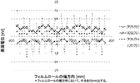
- FIG. 1 It is a schematic diagram showing an example of arrangement of a static eliminator in a process of static-eliminating a thermoplastic resin film in the manufacturing method of a film roll of the present invention. It is the graph which plotted the surface electric potential of the said film roll measured at 50 mm space
- both the maximum value and the minimum value of the surface potential measured at intervals of 50 mm in the width direction of the film roll are ⁇ 10 to +10 kV. If the maximum surface potential of the film roll exceeds 10 kV, dust may be collected, and if the minimum surface potential of the film roll is less than -10 kV, dust may be collected. From such a viewpoint, the maximum value of the surface potential of the film roll is preferably 7 kV or less, more preferably 4 kV or less, and the minimum value of the surface potential of the film roll is preferably -7 kV or more, more preferably Is -4 kV or more. The maximum value and the minimum value of the surface potential of the film roll can be measured using an electrostatic potential measuring device, and specifically, can be measured by the method described in Examples.
- the difference between the maximum value and the minimum value of the surface potential ((the maximum value of the surface potential)-(the minimum value of the surface potential) and the maximum value and the minimum value are the same) is 5 kV. It is below.
- the difference between the maximum value and the minimum value of the surface potential of the film roll is larger than 5 kV, the distribution of the charge amount on the surface of the film roll becomes non-uniform, the sticking between the films in the film roll becomes strong, and the minute wrinkles increase. May occur.
- the difference between the maximum value and the minimum value of the surface potential of the film roll is preferably 3.5 kV or less, more preferably 2.5 kV or less, and further preferably 1.5 kV or less. ..
- the surface potential of the film roll needs to be controlled over the entire width. Since the discharge device may have different discharge potential control or different discharge capability in the width direction, the film surface potential may be different in the film width direction after passing through the discharge device. When a film roll is produced in this state, parts having different surface potentials stick to each other, which causes sticking of the films and minute wrinkles after storage. In order to suppress sticking between films and minute wrinkles, when the potential in the width direction is measured at intervals of 50 mm in the width direction over the entire width of the film roll, the maximum and minimum potentials are both -10 to +10 kV. Therefore, it is important that the difference between the maximum value and the minimum value of the surface potential is 5 kV or less.
- the difference in surface potential between adjacent measurement points is preferably small, preferably 4 kV or less, more preferably 3 kV or less, even more preferably 2 kV or less.
- the film roll of the present invention comprises a thermoplastic resin film having a thickness of 250 ⁇ m or less. If the thickness of the thermoplastic resin film constituting the film roll of the present invention exceeds 250 ⁇ m, the rigidity of the film is high, and sticking due to electrification and minute wrinkles are less likely to occur, but there is a cost problem. .. From such a viewpoint, the thickness of the thermoplastic resin film constituting the film roll of the present invention is preferably 20 to 250 ⁇ m, more preferably 20 to 200 ⁇ m, further preferably 30 to 150 ⁇ m, and More preferably, it is 50 to 100 ⁇ m. The thickness of the thermoplastic resin film can be measured with a micrometer, and specifically can be measured by the method described in Examples.
- thermoplastic resin film which comprises the film roll of this invention consists of a thermoplastic resin composition, for example.
- the thermoplastic resin contained in the thermoplastic resin composition and forming the matrix portion in the film is not particularly limited, and examples thereof include polycarbonate; polystyrene, styrene-acrylonitrile resin, styrene-maleic anhydride resin, styrene-maleimide resin, Aromatic vinyl-based resins such as styrene-based thermoplastic elastomers or hydrogenated products thereof; amorphous polyolefins, transparent polyolefins having a refined crystal phase, polyolefin-based resins such as ethylene-methyl methacrylate resin; (meth)acrylic Resin: Polyethylene terephthalate, polyester resin such as polyethylene terephthalate, polyethylene naphthalate, polyarylate partially modified with cyclohexane dimethanol or isophthalic acid; polyamide resin; polyimide
- the (meth)acrylic resin (A) used as the thermoplastic resin forming the matrix portion in the thermoplastic resin film constituting the film roll of the present invention is a resin having a structural unit derived from a (meth)acrylic acid ester.
- a polymer mainly containing a structural unit derived from methyl methacrylate is preferable.
- the (meth)acrylic resin (A) is mainly composed of a structural unit derived from methyl methacrylate, the content of the structural unit derived from methyl methacrylate in the (meth)acrylic resin (A) depends on heat resistance.
- the content is at least mass%, and all structural units may be structural units derived from methyl methacrylate.
- the (meth)acrylic resin (A) may contain a structural unit derived from a monomer other than methyl methacrylate.
- the other monomer is not particularly limited as long as it is copolymerizable with methyl methacrylate, and examples thereof include methyl acrylate, ethyl acrylate, n-propyl acrylate, iso-propyl acrylate, n-butyl acrylate, Iso-butyl acrylate, sec-butyl acrylate, tert-butyl acrylate, amyl acrylate, isoamyl acrylate, n-hexyl acrylate, 2-ethylhexyl acrylate, pentadecyl acrylate, dodecyl acrylate, acrylic Phenyl acid, benzyl acrylate, phenoxyethyl acrylate, 2-hydroxyethyl acrylate, 2-ethoxyethyl acrylate, glycid
- Acid ester ethyl methacrylate, n-propyl methacrylate, iso-propyl methacrylate, n-butyl methacrylate, iso-butyl methacrylate, sec-butyl methacrylate, tert-butyl methacrylate, amyl methacrylate, isoamyl methacrylate.
- Methacrylic acid esters other than methyl methacrylate such as glycidyl methacrylate, allyl methacrylate, cyclohexyl methacrylate, norbornyl methacrylate, isobornyl methacrylate; acrylic acid, methacrylic acid, maleic anhydride, maleic acid, itaconic acid, etc.
- Unsaturated carboxylic acids or acid anhydrides such as ethylene, propylene, 1-butene, isobutylene and 1-octene; conjugated dienes such as butadiene, isoprene and myrcene; styrene, ⁇ -methylstyrene, p-methylstyrene, m -Aromatic vinyl compounds such as methylstyrene; acrylamide, methacrylamide, acrylonitrile, methacrylonitrile, vinyl acetate, vinylpyridine, vinyl ketone, vinyl chloride, vinylidene chloride, vinylidene fluoride and the like.
- olefins such as ethylene, propylene, 1-butene, isobutylene and 1-octene
- conjugated dienes such as butadiene, isoprene and myrcene
- styrene ⁇ -methylstyrene, p-methylstyrene, m
- acrylic acid esters are preferable, and methyl acrylate, ethyl acrylate, n-propyl acrylate, iso-propyl acrylate, n-butyl acrylate, iso-butyl acrylate, and sec-butyl acrylate are more preferable.
- the (meth)acrylic resin (A) used in the present invention may be used alone or in combination of two or more.
- the (meth)acrylic resin (A) is a polymer containing a structural unit derived from methyl methacrylate and a structural unit derived from a compound having a ring structure in the molecule such as maleic anhydride. Good. By containing the structural unit derived from the compound having a ring structure in the molecule, the heat resistance of the (meth)acrylic resin (A) and the resulting film are improved.
- the (meth)acrylic resin (A) contains a structural unit derived from a compound having a ring structure in the molecule, the total content thereof is preferably 1 to 40% by mass, more preferably 1 to 40% by mass. It is 20% by mass, more preferably 1 to 5% by mass.
- the structural unit derived from the compound having a ring structure in the molecule includes a structural unit derived from a compound containing a >CH—O—C( ⁇ O)— group in the ring structure, —C( ⁇ O)—O—C
- a structural unit derived from a compound having a ring structure in the molecule is a cyclic monomer having a polymerizable unsaturated carbon-carbon double bond such as maleic anhydride, N-substituted maleimide, etc. It may be contained in the (meth)acrylic resin (A) by polymerization or by intramolecular condensation cyclization of a part of the molecular chain of the (meth)acrylic resin (A) obtained by the polymerization. it can.
- the (meth)acrylic resin (A) contains a structural unit derived from a monomer other than methyl methacrylate, its content is preferably 50% by mass or less, and 20% by mass or less. It is more preferable that the amount is 10% by mass or less, further preferably 5% by mass or less, and particularly preferably 2% by mass or less.
- the glass transition temperature (Tg) of the (meth)acrylic resin (A) is preferably 80 to 140° C., more preferably 100 to 135° C., from the viewpoint of balance between heat resistance and moldability. , 105 to 130° C. is more preferable, and 105 to 125° C. is particularly preferable.
- the glass transition temperature can be adjusted by changing the type or amount of the monomer copolymerized with methyl methacrylate, or by changing the stereoregularity according to the polymerization temperature or the like.
- the glass transition temperature can be measured according to JIS K7121:2012. That is, the differential scanning calorimetry method was performed under the condition that the (meth)acrylic resin was once heated to 200° C., then cooled to 30° C. or lower, and then heated from 30° C. to 200° C. at 10° C./min.
- the glass transition temperature of the (meth)acrylic resin can be determined as the midpoint glass transition temperature obtained from the DSC curve measured by the above and the DSC curve measured during the second temperature increase.
- the stereoregularity of the (meth)acrylic resin (A) is not particularly limited, and for example, a (meth)acrylic resin having stereoregularity such as isotactic, heterotactic and syndiotactic can be used.
- the weight average molecular weight of the (meth)acrylic resin (A) is preferably 60,000 to 150,000.
- the weight average molecular weight is more preferably 85,000 to 120,000, and even more preferably 90,000 to 100,000.
- the weight average molecular weight of the (meth)acrylic resin (A) can be measured by the method described in Examples.
- the method for producing the (meth)acrylic resin (A) is not particularly limited, and can be obtained, for example, by polymerizing a monomer mainly containing methyl methacrylate.
- the weight average molecular weight of the (meth)acrylic resin (A) can be adjusted by the amount of the polymerization initiator and the chain transfer agent.
- the polymerization initiator used for producing the (meth)acrylic resin (A) is not particularly limited as long as it generates a reactive radical, and examples thereof include tert-hexyl peroxyisopropyl monocarbonate and tert-hexyl peroxy 2-.
- Examples of the chain transfer agent used for producing the (meth)acrylic resin (A) include n-octyl mercaptan, n-dodecyl mercaptan, tert-dodecyl mercaptan, 1,4-butanedithiol, 1,6-hexanedithiol and ethylene.
- Alkyl mercaptans such as pentaerythritol tetrakisthiopropionate, and the like.
- monofunctional alkyl mercaptans such as n-octyl mercaptan and n-dodecyl mercaptan are preferred.
- (meth)acrylic resin (A) a commercially available product may be used, for example, “Parapet H1000B” [MFR: 22 g/10 minutes (230° C., 37.3 N)], “Parapet GF” [MFR: 15 g /10 minutes (230° C., 37.3 N)], “parapet EH” [MFR: 1.3 g/10 minutes (230° C., 37.3 N)], “parapet HRL” [MFR: 2.0 g/10 minutes ( 230° C., 37.3 N)], “Parapet HRS” [MFR: 2.4 g/10 min (230° C., 37.3 N)] and “Parapet G” [MFR: 8.0 g/10 min (230° C., 37 .3 N)] [all are trade names, manufactured by Kuraray Co., Ltd.] and the like.
- the thermoplastic resin film forming the film roll of the present invention may contain rubber particles (B).
- the rubber particles (B) are preferably acrylic rubber particles (B-1) from the viewpoint of dispersibility and the like.
- Acrylic rubber particles (B-1) will be described as an example of the rubber particles (B).
- the acrylic rubber particles (B-1) have a multilayer structure having at least an elastic layer and an outer layer covering the elastic layer, from the viewpoints of dispersibility and transparency and mechanical properties of the obtained film. preferable. Further, from the viewpoint of improving impact resistance while keeping the hardness of the film high, it is more preferable to have a multilayer structure having an inner layer, an elastic layer covering the inner layer, and an outer layer covering the elastic layer.
- the elastic layer of the acrylic rubber particles (B-1) used in the present invention has a structure unit derived from an alkyl acrylate ester and a structure derived from a conjugated diene monomer from the viewpoint of adhesion to other layers.
- Crosslinked rubber polymer component containing 50% by mass or more of at least one monomer unit (I-1) selected from the group consisting of units (hereinafter, also simply referred to as “monomer unit (I-1)”) (I) is preferable, the crosslinked rubber polymer component (I) more preferably contains 60 to 99% by mass of the monomer unit (I-1), further preferably 70 to 95% by mass, It is even more preferable to contain 80 to 90% by mass.
- Examples of the crosslinked rubber polymer component (I) include homopolymers of acrylic acid alkyl ester, 50% by mass or more of structural units derived from acrylic acid alkyl ester, and structural units derived from monomers other than acrylic acid alkyl ester. And 50% by mass or less, a homopolymer of a conjugated diene monomer, a copolymer having a structural unit derived from a conjugated diene monomer of 50% by mass or more, and the like.
- a copolymer containing 50% by mass or more of the structural unit derived from the alkyl acrylate and 50% by mass or less of the structural unit derived from the monomer other than the alkyl acrylate. preferable.
- copolymer having a conjugated diene monomer unit of 50% by mass or more examples include, for example, rubber particles described in JP-A-10-182755 and acrylic graft copolymer described in JP-A-62-151415. Etc.
- the alkyl acrylate preferably has an alkyl group having 1 to 8 carbon atoms, more preferably 4 to 8 carbon atoms. Specifically, for example, methyl acrylate, ethyl acrylate, n-propyl acrylate, iso-propyl acrylate, n-butyl acrylate, iso-butyl acrylate, tert-butyl acrylate, 2-ethylhexyl acrylate, etc. Is mentioned. Among these, n-butyl acrylate and 2-ethylhexyl acrylate are preferable, and n-butyl acrylate is more preferable.
- the crosslinked rubber polymer component (I) has a crosslinked structure.
- the crosslinked structure may be formed by irradiation with an electron beam, or may be formed by using a polyfunctional monomer as the monomer of the crosslinked rubber polymer component (I).
- a polyfunctional monomer as the monomer of the crosslinked rubber polymer component (I).
- examples of such polyfunctional monomers include alkenyl esters of unsaturated carboxylic acids such as allyl (meth)acrylate and methallyl (meth)acrylate; dialkenyl esters of dibasic acids such as diallyl maleate; alkylene glycol di(meth) )
- Examples include unsaturated carboxylic acid diesters of glycols such as acrylate.
- alkenyl ester of unsaturated carboxylic acid is preferable, allyl (meth)acrylate is more preferable, and allyl methacrylate is further preferable.
- the content of the polyfunctional monomer unit in the crosslinked rubber polymer component (I) is from the viewpoint of improving the mechanical strength of the acrylic rubber particles (B-1) by crosslinking and improving the impact resistance of the resin composition. From the viewpoint of balance with fluidity, it is preferably 0.01 to 5% by mass, more preferably 0.05 to 4% by mass, and further preferably 0.1 to 3% by mass.
- the crosslinked rubber polymer component (I) preferably contains a structural unit derived from a monomer other than the alkyl acrylate and the polyfunctional monomer.
- monomers include alkyl methacrylates such as methyl methacrylate and ethyl methacrylate; aromatic group-containing (meth)acrylates such as benzyl (meth)acrylate and phenyl (meth)acrylate; styrene and alkyl Examples thereof include styrene-based monomers such as styrene; unsaturated nitriles such as acrylonitrile and methacrylonitrile.
- aromatic compounds are preferable from the viewpoint of adjusting the refractive index
- styrene-based monomers and aromatic group-containing (meth)acrylic acid esters are more preferable
- styrene-based monomers are further preferable
- styrene is further preferable.
- the content of the structural unit derived from the aromatic compound in the crosslinked rubber polymer component (I) is preferably 1 to 40% by mass, more preferably 5 to 30% by mass, from the viewpoint of the refractive index. More preferably, it is 10 to 20% by mass.
- the elastic layer may contain a plurality of crosslinked rubber polymer components (I) having different compositions, and the elastic layer may contain components other than the crosslinked rubber polymer component (I).
- the content of the crosslinked rubber polymer component (I) in the elastic layer is preferably 80% by mass or more, more preferably 90% by mass or more, and further preferably 100% by mass.
- the acrylic rubber particles (B-1) preferably have an inner layer inside the elastic layer from the viewpoint of improving the mechanical properties of the film, that is, improving the impact resistance while maintaining high hardness. It is preferable to include a polymer component (II) containing 50% by mass or more of a structural unit derived from an alkyl methacrylate.
- the polymer component (II) may have a covalent bond with the crosslinked rubber polymer component (I).
- the content of the structural unit derived from the methacrylic acid alkyl ester in the polymer component (II) is preferably 60 to 99% by mass, more preferably 70 to 99% by mass, further preferably 80 to 99% by mass.
- methacrylic acid alkyl ester examples include methyl methacrylate and ethyl methacrylate, and of these, methyl methacrylate is preferable.
- the polymer component (II) preferably has a crosslinked structure in its molecule from the viewpoint of improving the mechanical strength of the acrylic rubber particles (B-1).
- a crosslinked structure is preferably formed by using a polyfunctional monomer as the monomer of the polymer component (II).
- the polyfunctional monomer include those similar to the above-mentioned crosslinked rubber polymer component (I). Among them, alkenyl ester of unsaturated carboxylic acid is preferable, allyl (meth)acrylate is more preferable, and allyl methacrylate is more preferable.
- the polyfunctional monomer unit in the polymer component (II) is preferably 0.1 to 5% by mass, more preferably 0.15 to 1% by mass, and further preferably 0 from the viewpoint of mechanical properties. 18 to 0.5% by mass.
- the polymer component (II) may have a unit derived from a monomer other than the methacrylic acid alkyl ester and the polyfunctional monomer.
- monomers include alkyl acrylates such as methyl acrylate, ethyl acrylate, propyl acrylate, n-butyl acrylate, and 2-ethylhexyl acrylate; styrene-based monomers such as styrene and alkylstyrene; Examples thereof include unsaturated nitriles such as acrylonitrile and methacrylonitrile.
- alkyl acrylates are preferable, and methyl acrylate is more preferable.
- the content of the structural unit derived from a monomer other than the methacrylic acid alkyl ester in the polymer component (II) is preferably 40% by mass or less, more preferably 30% by mass or less, and further preferably 20% by mass or less. It is at most mass%, more preferably at most 15 mass%, particularly preferably at most 10 mass%.
- the inner layer may contain a plurality of polymer components (II) having different compositions, and may contain components other than the polymer component (II). However, the content of the polymer component (II) in the inner layer is preferably 80% by mass or more, more preferably 90% by mass or more, and further preferably 100% by mass.
- the mass ratio of the polymer component (II) to the crosslinked rubber polymer component (I) [polymer component (II)/crosslinked rubber polymer component (I)] is preferably 5/95 to 90/10, and It is preferably 10/90 to 70/30, more preferably 20/80 to 60/40, and even more preferably 30/70 to 50/50.
- the mass ratio is calculated from the mass ratio of the monomer mixture of these polymer components.
- the outer layer constituting the acrylic rubber particles (B-1) contains 75% by mass or more of methyl methacrylate unit and contains the hard polymer component (III) graft-bonded to the crosslinked rubber polymer component (I). Is preferred.
- the hard polymer component (III) has a methyl methacrylate unit content of 75 to 99 mass. % And acrylic acid ester units 1 to 25% by mass, more preferably 80 to 97% by mass of methyl methacrylate units and 3 to 20% by mass of acrylic acid ester units, and more preferably 90% of methyl methacrylate units. It is more preferable to contain ⁇ 96% by mass and 4 to 10% by mass of acrylic acid ester unit.
- ester group of the acrylic ester used for the hard polymer component (III) examples include an alkyl group, a cycloalkyl group, a phenyl group and their derivatives having 1 to 12 carbon atoms.
- Specific acrylic acid esters include, for example, methyl acrylate, ethyl acrylate, n-propyl acrylate, iso-propyl acrylate, n-butyl acrylate, iso-butyl acrylate, tert-butyl acrylate, acrylic acid.
- Examples thereof include 2-ethylhexyl, n-octyl acrylate, n-lauryl acrylate, 2-hydroxyethylhexyl acrylate, cyclohexyl acrylate, isobornyl acrylate, tetrahydrofuryl acrylate, benzyl acrylate, phenyl acrylate and the like.
- methyl acrylate, n-butyl acrylate, cyclohexyl acrylate, and benzyl acrylate are preferable from the viewpoint of the balance of adhesion with active energy ray-curable hard coat and adhesive, heat resistance, handleability, and the like. preferable.
- the outer layer may contain a plurality of hard polymer components (III) having different compositions, or may contain components other than the hard polymer component (III).
- the content of the hard polymer component (III) in the outer layer is preferably 80% by mass or more, more preferably 90% by mass or more, and further preferably 100% by mass.
- the hard polymer component (III) is preferably graft-bonded to the crosslinked rubber polymer component (I).
- the graft ratio of the acrylic rubber particles (B-1) is preferably 11 to 33%, more preferably 15 to 30%, still more preferably 20 to 30%.
- the graft ratio is defined by the mass ratio of the hard polymer component (III) which is graft-bonded to the crosslinked rubber polymer component (I), and when the graft ratio is 11% or more, the heat resistance is improved. % Or less, the adhesion with the active energy ray-curable resin is improved.
- the mass of the crosslinked rubber polymer component (I) is the total mass of the monomers of the crosslinked rubber polymer component (I) in the polymerization.
- the mass of the crosslinked rubber polymer component (I) in the above formula (a) is equal to the crosslinked rubber polymer component (I).
- the proportion of the hard polymer component (III) in the acrylic rubber particles (B-1) is preferably 5 to 50% by mass, more preferably 10 to 30% by mass, further preferably 10 to 25% by mass, It is particularly preferably 15 to 22% by mass.
- the ratio of the hard polymer component (III) in the acrylic rubber particles (B-1) is graft-bonded to the crosslinked rubber polymer component (I) by 100% by mass.
- the graft ratio of the acrylic rubber particles (B-1) can be set within the above range, and the degree of freedom of the blending amount of the graft-bonding polyfunctional monomer increases.
- the degree of swelling of the acrylic rubber particles (B-1) due to the impregnation with the active energy ray-curable resin can be controlled more accurately, and it becomes easier to achieve both adhesion and suppression of whitening.
- the apparent number average molecular weight of the hard polymer component (III) is preferably 10,000 to 100,000, more preferably 15,000 to 60,000, and further preferably 30,000 to 50,000. Is. When the apparent number average molecular weight is 10,000 or more, heat resistance is improved, and when it is 100,000 or less, adhesion is improved.
- the apparent number average molecular weight of the hard polymer component (III) is the same as that of the crosslinked rubber polymer component when the monomer mixture at the time of producing the hard polymer component (III) of the acrylic rubber particles (B-1) is produced.
- the hard polymer component (A-1) of the acrylic rubber particles (B-1) is provided under the condition that (I) does not exist, and the crosslinked rubber polymer component (I) and the polymer component (II) do not exist when the inner layer is present.
- the apparent number average molecular weight can be adjusted by the blending amount of a chain transfer agent such as mercaptan.
- the average particle size of the acrylic rubber particles (B-1) is preferably 0.03 to 0.50 ⁇ m, more preferably 0.07 to 0.40 ⁇ m, and 0 from the viewpoint of impact resistance. More preferably, it is from 0.15 to 0.30 ⁇ m.
- the average particle diameter in the present specification is an arithmetic average value in a volume-based particle diameter distribution measured by a light scattering method, and specifically, it can be obtained by the method described in Examples.
- the polymerization initiator used for producing the acrylic rubber particles (B-1) is not particularly limited as long as it generates a reactive radical, and examples thereof include water-soluble inorganic initiators such as potassium persulfate and ammonium persulfate.
- Examples of the chain transfer agent used for producing the acrylic rubber particles (B-1) include n-octyl mercaptan, n-dodecyl mercaptan, tert-dodecyl mercaptan, 1,4-butanedithiol, 1,6-hexanedithiol and ethylene.
- Alkyl mercaptans such as pentaerythritol tetrakisthiopropionate, and the like.
- monofunctional alkyl mercaptans such as n-octyl mercaptan and n-dodecyl mercaptan are preferred.
- the content of the rubber particles (B) in the thermoplastic resin film constituting the film roll of the present invention is 2 to 95% by mass based on the mass of the thermoplastic resin film from the viewpoint of moldability and mechanical properties. It is more preferably from 3 to 90% by mass, even more preferably from 4 to 85% by mass, even more preferably from 5 to 84% by mass, particularly preferably from 10 to 83% by mass. ..
- the thermoplastic resin film that constitutes the film roll of the present invention may contain various additives as required, as long as the effects of the present invention are not impaired.
- the type of additive is not particularly limited, and examples thereof include ultraviolet absorbers, polymer processing aids, light stabilizers, antioxidants, heat stabilizers, lubricants, antistatic agents, pigments, dyes, delustering agents, and fillers. , Impact resistance assistants, plasticizers and the like.
- the additive one kind may be used alone, or two kinds or more may be used in optional ratio in combination.
- the additive may be an organic compound or an inorganic compound, but the organic compound is preferable from the viewpoint of dispersibility in the resin composition.
- thermoplastic resin film forming the film roll of the present invention can be used for the following various applications.
- thermoplastic resin film constituting the film roll of the present invention is suitable for an optical film because of its excellent heat resistance and optical properties, and can be used for various optical members.
- image fields such as cameras, VTRs, shooting lenses for projectors, viewfinders, filters, prisms, Fresnel lenses, lens covers; lens fields such as pickup lenses for optical disks in CD players, DVD players, MD players, etc.; CDs, DVDs Optical recording field for optical disks such as MD, MD; Front panel of liquid crystal screen of terminals such as mobile phones, smartphones, tablets; Vehicle fields such as automobile headlight tail lamp lens, inner lens, instrument cover, sunroof, etc.; Lighting lens; Liquid crystal Film for liquid crystal display such as light guide plate, diffuser plate, back sheet, reflection sheet, polarizing film transparent resin sheet, retardation film, light diffusion film, prism sheet, optically isotropic film, polarizer protective film, transparent conductive film, etc.
- liquid crystal display devices such as: Information equipment fields such as surface protection films; Around organic EL devices as organic EL films; Optical communication fields such as optical fibers, optical switches, optical connectors; Optical lenses; Optical discs and other known optics It can be applied to specific purposes.
- thermoplastic resin film constituting the film roll of the present invention is used as a laminated film in which at least one surface is laminated with a layer made of a metal and/or a metal oxide, another layer such as another thermoplastic resin layer.
- a layer made of a metal and/or a metal oxide another layer such as another thermoplastic resin layer.
- Another layer such as another thermoplastic resin layer.
- the method of laminating other layers is not particularly limited, and they can be bonded directly or through an adhesive layer or the like.
- the other layer may be a single layer or a laminate of a plurality of layers.
- thermoplastic resin film forming the film roll of the present invention may be printed on at least one surface.
- patterns, colors such as pictures, characters, and figures are added.
- the pattern may be chromatic or achromatic.
- thermoplastic resin film forming the film roll of the present invention can be used by laminating it on metal, plastic or the like.
- laminating molding wet laminating in which an adhesive is applied to a metal plate such as a steel plate, and then the film is placed on the metal plate and dried and bonded, dry laminating, extrusion laminating, hot melt laminating and the like. Can be mentioned.
- a film is placed in a mold, and insert molding or laminate injection press molding in which a resin is filled by injection molding, or a film is preformed and then placed in a mold, Examples include in-mold molding in which a resin is filled by injection molding.
- Laminates containing a thermoplastic resin film constituting the film roll of the present invention automotive interior materials, coating alternative applications such as automotive exterior materials, window frames, bathroom equipment, wallpaper, building material members such as flooring materials, daily sundries Products, housings for furniture and electric equipment, housings for office automation equipment such as facsimiles, laptops, copiers, front plates of liquid crystal screens of terminals such as mobile phones, smartphones, tablets, lighting lenses, automobile headlights, optical lenses , Optical fiber, optical disk, optical member such as liquid crystal light guide plate, electric or electronic device parts, medical supplies requiring sterilization, toys or recreation items, etc.
- thermoplastic resin composition of the thermoplastic resin film constituting the film roll of the present invention
- thermoplastic resin for example, the thermoplastic resin and, if necessary, rubber particles and various additives. And the like.
- the apparatus for melt kneading include a kneader ruder, a twin-screw extruder, a single-screw extruder, a mixing roll, and a Banbury mixer.
- a twin-screw extruder is preferable from the viewpoint of kneading properties, and a twin-screw extruder with a vent is more preferable from the viewpoint of suppressing coloration.
- the vented twin-screw extruder is preferably operated under reduced pressure or with nitrogen flowing.
- the shear rate at the time of melt-kneading is preferably 10 to 1000/sec.
- the temperature at the time of kneading is preferably 110 to 300°C, more preferably 180 to 300°C, and further preferably 230 to 270°C.
- the thermoplastic resin composition melt-kneaded by an extruder is extruded in a strand shape and can be cut into pellets by a pelletizer or the like.
- the thermoplastic resin film forming the film roll of the present invention is obtained by molding the thermoplastic resin composition.
- the molding method is not particularly limited, and known molding methods such as extrusion molding (T die method, etc.), injection molding, compression molding, inflation molding, blow molding, calender molding, cast molding, and vacuum molding can be adopted.
- the extrusion molding method is preferably adopted. According to the extrusion molding method, particularly the T-die method, it is possible to obtain a thermoplastic resin film having improved toughness, excellent handleability, and excellent balance between toughness and surface hardness and rigidity.
- the extruder used for the extrusion molding method, particularly the T-die method preferably has a single screw or a twin screw.
- thermoplastic resin film from the viewpoint of suppressing coloring of the thermoplastic resin film, it is preferable to perform melt extrusion under reduced pressure using a vent. Further, from the viewpoint of obtaining a thermoplastic resin film having a uniform thickness, it is preferable to connect a gear pump to the extruder and further perform melt extrusion through a polymer filter in order to reduce fisheye defects. Further, from the viewpoint of suppressing oxidative deterioration, it is preferable to perform melt extrusion under a nitrogen stream.
- the temperature of the material discharged from the extruder is preferably 230 to 290°C, more preferably 240 to 280°C.
- the extruded film-like molten resin is drawn and sandwiched between the mirror roll and/or the mirror belt.
- Both the mirror surface roll and the mirror surface belt are preferably made of metal.
- the linear pressure between the mirror surface roll and/or the mirror surface belt is preferably 10 N/mm or more, and more preferably 30 N/mm or more, from the viewpoint of surface smoothness.
- the surface temperature of the mirror surface roll and/or the mirror surface belt is preferably 60° C. or higher, and more preferably 70° C. or higher from the viewpoint of surface smoothness, haze, appearance and the like. Further, it is preferably 130° C. or lower, and more preferably 100° C. or lower.
- the thermoplastic resin film constituting the film roll of the present invention may be formed into a film shape and then subjected to a stretching treatment.
- the stretching treatment improves the mechanical strength of the thermoplastic resin film, making it less likely to crack.
- the stretching method is not particularly limited, and includes a simultaneous biaxial stretching method, a sequential biaxial stretching method, a tuber stretching method, a rolling method and the like.
- the temperature during stretching is preferably 5° C. or higher than the glass transition temperature of the thermoplastic resin film, and preferably 40° C. or higher than the glass transition temperature of the thermoplastic resin film.
- the stretching speed is preferably 100 to 5000%/min.
- the thermoplastic resin film may be colored.
- a coloring method for example, a method of coloring the material itself before film formation by incorporating a pigment or dye into the material forming the thermoplastic resin film; immersing the thermoplastic resin film in a liquid in which the dye is dispersed Examples include dyeing methods for coloring.
- the method for producing the film roll of the present invention is not particularly limited, but because the film roll of the present invention can be obtained more efficiently, etc., the thermoplastic resin film produced as described above is wound on a film roll. At that time, a static eliminator is arranged at a position within 5 m to the winding contact point of the thermoplastic resin film along the flow direction of the film to pre-staticize the thermoplastic resin film before being wound on the film roll, and the static eliminator concerned. It is preferable to adopt a method in which the distance between the discharge part and the thermoplastic resin film is 30 to 100 mm.
- the present invention is a method for manufacturing a film roll made of a thermoplastic resin film having a thickness of 250 ⁇ m or less, wherein the static eliminator is located within 5 m from the winding contact point of the thermoplastic resin film along the flow direction of the film.
- Having a step of destaticizing the thermoplastic resin film by arranging, and a step of winding up the thermoplastic resin film destaticized in the step, and the distance between the discharge part of the destaticizing device and the thermoplastic resin film is It includes a method for producing a film roll having a thickness of 30 to 100 mm.
- FIG. 1 is a schematic view showing an arrangement example of a static eliminator in a step of static eliminating a thermoplastic resin film in the method for producing a film roll of the present invention.
- the arrow in FIG. 1 indicates the flow direction of the film.
- the thermoplastic resin film 1 obtained as described above is transported by the transport roll 2 and wound into a roll to form a film roll 4.
- the static eliminator 3 is arranged at a position within 5 m from the winding contact P of the thermoplastic resin film 1 along the flow direction of the film, and neutralizes the thermoplastic resin film 1.
- the static eliminator when the static eliminator is arranged at a position more than 5 m away from the winding contact point of the thermoplastic resin film along the flow direction of the film, the static eliminated thermoplastic resin film rubs against a transport roll or the like during transport. There is a possibility that the film roll may be charged again and dust and minute wrinkles may occur on the obtained film roll. Further, the maximum value and the minimum value of the surface potential of the film roll, and the difference between the maximum value and the minimum value of the surface potential may be out of the above range. From such a viewpoint, the static eliminator is preferably arranged within 4 m to the winding contact of the thermoplastic resin film along the flow direction of the film, more preferably within 3 m, and more preferably within 2 m. More preferably.
- the static eliminator is installed at the position of the winding contact of the thermoplastic resin film or at the position after the winding, the static elimination effect may be limited to only one side, which is not preferable from the viewpoint of the uniformity of the charged state. ..
- the static eliminator is preferably installed 0.05 m or more in front of the winding contact point of the thermoplastic resin film along the flow direction of the film, more preferably 0.2 m or more, and more preferably 0.2 m or more. It is more preferable to install them at a distance of 5 m or more.
- the distance between the static eliminator and the winding contact may be the distance from the position closest to the winding contact of the discharge part of the static eliminator to the position corresponding to the winding contact along the film flow direction.
- the distance between the discharge part of the static eliminator and the thermoplastic resin film is 30 to 100 mm, preferably 40 to 70 mm.
- the distance between the discharge part of the static eliminator and the thermoplastic resin film is less than 30 mm, uneven static erasing occurs in the width direction of the film in the case of the DC static eliminator and in the flow direction of the film in the case of the AC static eliminator.
- the generated wind causes vibration of the film, and a winding failure is likely to occur.
- the distance between the discharge part of the static eliminator and the thermoplastic resin film exceeds 100 mm, the static elimination of the thermoplastic resin film becomes non-uniform and the thermoplastic resin films tend to stick to each other.
- the processing time for static elimination becomes long, and there is a possibility that the charge amount may increase when the thermoplastic resin film is wound at high speed.
- the distance between the discharge portion of the static eliminator and the thermoplastic resin film within the above range, the maximum and minimum values of the surface potential of the film roll, and the difference between the maximum and minimum values of the surface potential are as described above. Within the range, the effect of the present invention can be exhibited. Further, by setting the distance between the discharge part of the static eliminator and the thermoplastic resin film to be 30 mm or more, it is possible to suppress unevenness of static erasing, and it is possible to suppress generation of dust on the obtained film roll. ..
- a DC type static eliminator As the static eliminator, a DC type static eliminator, an AC type static eliminator, a pulse type static eliminator, etc. can be used, and as other static eliminators, ion air blowing, static eliminator brush, static eliminator, vapor space humidifier, etc. are used. You can also As a preferable method of static elimination, there are a DC static eliminator, an AC static eliminator and a pulse static eliminator, which can reduce the charge amount of the thermoplastic resin film in a short time. Further, by supplying air to these static eliminators, it is possible to assist the diffusion of ions generated from the static eliminators, and to eliminate static electricity at higher speed.
- the static elimination method may be carried out by using one kind alone, or a combination of plural kinds. Further, one type of static elimination method may be performed plural times.
- the discharge potential of the static eliminator (preferably the static eliminator located at the most downstream) arranged in front of the winding contact along the flow direction of the film and arranged at the position closest to the winding contact is preferably ⁇ It is 20 to +20 kV.
- the discharge potential of each static eliminator is preferably ⁇ 20 to +20 kV.
- the static elimination device used for the static elimination of at least one of them is arranged within 5 m to the winding contact point of the thermoplastic resin film along the flow direction of the film.
- the location of the static eliminator is not particularly limited, but from the viewpoint of more effectively exerting the effects of the present invention, it is preferably within 50 m to the winding contact point of the thermoplastic resin film along the film flow direction, and 30 m It is more preferably within the range.
- each charge removal may be performed on the same surface of the thermoplastic resin film or on different surfaces thereof.
- the static elimination device used may be the same or different.
- the transport speed of the film in the static elimination step is preferably 5 to 100 m/min, more preferably 10 to 50 m/min, and further preferably 15 to 30 m/min.
- the film roll of the present invention can be obtained by winding the thermoplastic resin film, which has been neutralized in this step, into a roll.
- the film roll of the present invention has a uniform charged state, and can prevent films from sticking to each other, dust collection, and fine wrinkles.
- the maximum value and the minimum value of the surface potential of the film roll can be measured using an electrostatic potential measuring device, and specifically, can be measured by the method described in Examples.
- the diameter of the film roll of the present invention is preferably 300 to 1000 mm, more preferably 400 to 700 mm. When the diameter of the film roll is within the above range, the effect of the present invention is easily exhibited.
- the present invention will be described more specifically below with reference to Examples and Comparative Examples.
- the present invention is not limited to the examples below. Further, the present invention includes all modes in which the items representing technical features such as characteristic values, forms, manufacturing methods, and uses described in the above-mentioned embodiment and examples below are arbitrarily combined.
- Film thickness Using a film thickness meter (manufactured by Mitutoyo Co., Ltd., high precision Digimatic Micrometer MDH-25M), the film width direction was uniformly measured at 5 points. The average value was used as the film thickness.
- the weight average molecular weight (Mw) was determined by GPC (gel permeation chromatography) in terms of standard polystyrene equivalent molecular weight.
- the measuring device and conditions are as follows. ⁇ Device: GPC device "HLC-8320" manufactured by Tosoh Corporation ⁇ Separation column: Tosoh Co., Ltd. "TSKgel SuperMultipore HZM-M” and “Super HZ4000” are directly connected. Detector: Tosoh Co., Ltd. "RI-8020”.
- ⁇ Eluent Tetrahydrofuran
- Eluent flow rate 0.35 mL/min
- ⁇ Sample concentration 8 mg/10 mL
- Column temperature 40°C
- the temperature of the (meth)acrylic resin (A-1) is once raised to 200° C., then cooled to 30° C. or lower, and then 30° C. to 200° C. at 10° C./min.
- the DSC curve is measured by a differential scanning calorimetry method under the condition of raising the temperature, and the midpoint glass transition temperature obtained from the DSC curve measured at the time of the second heating is calculated as the (meth)acrylic resin (A-1 ) Glass transition temperature.
- the average particle size is measured at 25° C. by using a laser diffraction/scattering particle size distribution measuring device (manufactured by Horiba, Ltd., device name “LA-950V2”) after diluting latex containing sample particles 200 times. The diluted solution was analyzed and the particle size was measured. At this time, the absolute refractive indexes of the acrylic rubber particles (B-1) and water were set to 1.4900 and 1.3333, respectively.
- An electrostatic potential measuring device (digital electrostatic potential measuring device KSD-1000 manufactured by Kasuga Denki Co., Ltd.) was placed at a position 100 mm away from the surface of the film roll in the radial direction.
- the electrostatic potential measuring device measured the surface potential of a film roll having a total width of 1450 mm at 29 points at 50 mm intervals in the width direction of the film roll.
- the difference (potential difference) (maximum potential-minimum potential) was determined from the maximum value (maximum potential) and the minimum value (minimum potential).
- the mixed liquid and the raw material liquid (total of 9000 kg) were charged into a pressure resistant polymerization tank, and the temperature was raised to 70° C. to start the polymerization reaction while stirring in a nitrogen atmosphere. After 3 hours from the start of the polymerization reaction, the temperature was raised to 90° C. and stirring was continued for 1 hour to obtain a liquid in which the bead-like copolymer was dispersed. Although some polymer adhered to the wall of the polymerization tank or the stirring blade, the polymerization reaction proceeded smoothly without foaming.
- the obtained copolymer dispersion was washed with an appropriate amount of ion-exchanged water, the bead-shaped copolymer was taken out by a bucket centrifuge, and dried in a hot air dryer at 80° C. for 12 hours to give a bead-shaped (meta )
- An acrylic resin (A-1) was obtained.
- the obtained (meth)acrylic resin (A-1) had a methyl methacrylate unit content of 99.3% by mass, a methyl acrylate unit content of 0.7% by mass, and a weight average molecular weight (Mw ) Was 92,000 and the glass transition temperature was 120°C.
- the latex containing the acrylic rubber particles (B-1) was obtained by the above operation, the latex containing the acrylic rubber particles (B-1) was frozen and coagulated. Then, it was washed with water and dried to obtain acrylic rubber particles (B-1). The particles had an average particle diameter of 0.23 ⁇ m and a graft ratio of 23%.
- Example 1 80 parts by mass of the (meth)acrylic resin (A-1) and 20 parts by mass of the acrylic rubber particles (B-1) are mixed by a Henschel mixer, and a twin screw extruder with a vent having a screw diameter of 58 mm set to 230° C. A pellet of the thermoplastic resin composition was obtained using a machine. The pellets are supplied to a hopper of a single-screw extruder with a vent, melt-kneaded at 260° C., passed through a gear pump, a filter device, and a static mixer in this order, and formed into a film from a T die (die width 1700 mm) with a lip opening of 1 mm.
- thermoplastic resin film After peeling the thermoplastic resin film from the final metal rigid roll, the thermoplastic resin film is conveyed at a speed of 20 m/min, and at a position of 40 m to the winding contact point of the thermoplastic resin film along the flow direction of the film.
- a direct current static eliminator bar type static eliminator KDB-1800/KD-309BS manufactured by Kasuga Electric Co., Ltd.
- the discharge electrode needle is made of tungsten at a distance of 50 mm in the direction perpendicular to the surface of the resin film. (Static elimination) was installed to eliminate static electricity from the thermoplastic resin film.
- thermoplastic resin film is transported, and a distance of 50 mm is provided in a direction perpendicular to the transport surface of the thermoplastic resin film at a position of 2 m to the winding contact along the flow direction of the film, and the discharge electrode is formed.
- An AC static eliminator (smart AC ionizer ASIBS-1800, manufactured by Kasuga Denki Co., Ltd.) with a needle of tungsten (3rd static eliminator) was installed, and the ion balance of the AC static eliminator was set to neutral (N), from the inner surface of the film winding.
- N neutral
- the film was wound into a roll to obtain a film roll made of a thermoplastic resin film having a thickness of 80 ⁇ m.
- the maximum potential of the obtained film roll was 2 kV, the minimum potential was 1 kV, and the potential difference between the maximum potential and the minimum potential was 1 kV.
- the evaluation results are shown in Table 1. All of the static eliminators used had a discharge potential of -20 to +20 kV.
- Example 2 A film roll was obtained in the same manner as in Example 1 except that the ion balance of the third charge removal was negative. The evaluation results are shown in Table 1. Moreover, the graph which plotted the surface potential in each measurement location was shown in FIG.
- Example 3 A film roll was obtained in the same manner as in Example 1 except that the ion balance of the third charge removal was positive. The evaluation results are shown in Table 1. Moreover, the graph which plotted the surface potential in each measurement location was shown in FIG.
- Example 4 A film roll was obtained in the same manner as in Example 1 except that the second charge removal was not performed. The evaluation results are shown in Table 1. Moreover, the graph which plotted the surface potential in each measurement location was shown in FIG.
- Example 5 A film roll was obtained in the same manner as in Example 1 except that the distance from the static eliminator for the third static eliminator to the winding contact was changed to 5 m along the flow direction of the film. The evaluation results are shown in Table 1.
- Example 6 A film roll was obtained in the same manner as in Example 1 except that the distance from the static eliminator for the third static eliminator to the winding contact was changed to 0.3 m along the flow direction of the film. The evaluation results are shown in Table 1.
- Example 1 A film roll was obtained in the same manner as in Example 1 except that the distance from the static eliminator for the third static eliminator to the winding contact was changed to 10 m along the flow direction of the film. The evaluation results are shown in Table 1.
- Example 2 A film roll was obtained in the same manner as in Example 1 except that the distance from the static eliminator for the third static eliminator to the winding contact was changed to 15 m along the flow direction of the film. The evaluation results are shown in Table 1.
- Example 3 (Comparative example 3) Example 1 except that the distance from the static eliminator of the third static eliminator to the winding contact was changed to 3 m along the flow direction of the film, and the distance from the discharge part of the static eliminator to the surface of the thermoplastic resin film was changed to 10 mm. A film roll was obtained in the same manner. The evaluation results are shown in Table 1. Moreover, the graph which plotted the surface potential in each measurement location was shown in FIG.
- Example 4 In Example 1, except that the distance from the static eliminator for the third static eliminator to the winding contact was changed to 3 m and the distance from the discharge part of the static eliminator to the surface of the thermoplastic resin film was changed to 20 mm along the flow direction of the film. A film roll was obtained in the same manner as in Example 1. The evaluation results are shown in Table 1.
- the maximum and minimum surface potentials of the film rolls are both ⁇ 10 to +10 kV, and the film rolls of Examples 1 to 6 in which the difference between the maximum and minimum surface potentials is 5 kV or less are all There were few fine wrinkles immediately after winding and after storage, and there was little sticking of films to each other or adhesion of dust.
Landscapes
- Manufacture Of Macromolecular Shaped Articles (AREA)
- Winding Of Webs (AREA)
- Feeding Of Articles By Means Other Than Belts Or Rollers (AREA)
Abstract
厚さ250μm以下の熱可塑性樹脂フィルムからなるフィルムロールであって、幅方向に50mm間隔で測定した当該フィルムロールの表面電位の最大値及び最小値がいずれも-10~+10kVであり、表面電位の最大値と最小値との差が5kV以下である、フィルムロール;および、厚さ250μm以下の熱可塑性樹脂フィルムからなるフィルムロールの製造方法であって、巻取接点まで5m以内の位置に除電装置を配置して熱可塑性樹脂フィルムを除電する工程と、除電した熱可塑性樹脂フィルムを巻き取る工程と、を有し、除電装置の放電部と熱可塑性樹脂フィルムとの距離が30~100mmである、製造方法。
Description
本発明は、フィルムロール及びその製造方法に関する。
樹脂からなるフィルムは成形体の材料として有用であり、中でもアクリル系樹脂フィルムは、その高い透明性から、光学部材、照明部材、看板部材、装飾部材等の材料に好適に用いられる。
ところで、アクリル系樹脂フィルムを形成するアクリル系樹脂は帯電列に示されるように強く帯電することが知られており、非特許文献1では、アクリルはトリアセチルセルロースやポリカーボネート、塩化ビニルよりも正に帯電することが報告されている。
フィルム製膜時や搬送時には、キャストロールからの剥離や、ニップローラーとの摩擦によりフィルムが強く帯電し、帯電により様々な問題が起こる。
具体的には、例えばアクリル系樹脂フィルムの帯電により空気中の塵やホコリを収集し(集塵)、光学部材として使用する際の欠点となる。また、フィルム同士の張り付きにより微小なシワが発生し、アクリル系樹脂フィルムに塗料などを塗布する際の外観不良を引き起こす。
ところで、アクリル系樹脂フィルムを形成するアクリル系樹脂は帯電列に示されるように強く帯電することが知られており、非特許文献1では、アクリルはトリアセチルセルロースやポリカーボネート、塩化ビニルよりも正に帯電することが報告されている。
フィルム製膜時や搬送時には、キャストロールからの剥離や、ニップローラーとの摩擦によりフィルムが強く帯電し、帯電により様々な問題が起こる。
具体的には、例えばアクリル系樹脂フィルムの帯電により空気中の塵やホコリを収集し(集塵)、光学部材として使用する際の欠点となる。また、フィルム同士の張り付きにより微小なシワが発生し、アクリル系樹脂フィルムに塗料などを塗布する際の外観不良を引き起こす。
帯電を除去する方法として、除電装置を用いた方法がこれまで報告されており、例えば、特許文献1には、フィルム保管時のシワの抑制、及びフィルム巻取時の巻ズレが抑制されたフィルムの製造方法が開示されている。また、特許文献2には、剥離帯電などで塵埃が付着し易くなることによる不具合を低減する保護フィルムの製造方法が開示されている。
繊維学会編、繊維便覧(原料編)、丸善(1968)、263頁
しかしながら、従来の除電方法を帯電しやすいアクリル系樹脂フィルムに適用しただけでは、除電が不十分であり、除電後にフィルムを搬送するだけで再度強く帯電し、フィルム同士の張り付き、集塵及び微小なシワの発生が生じやすくなり、これらを抑制することが困難であった。
本発明は、このような実情に鑑みてなされたものであり、帯電状態が均一であり、フィルム同士の張り付き、集塵の発生及び微小なシワの発生を抑制することができるフィルムロール、及び当該フィルムロールの製造方法を提供することを目的とする。
本発明者らは、前記の課題を解決するべく鋭意検討した結果、下記の発明により当該課題を解決できることを見出し、本発明を完成するに至った。
すなわち、本発明は、次の[1]~[6]を提供するものである。
[1]厚さ250μm以下の熱可塑性樹脂フィルムからなるフィルムロールであって、前記フィルムロールの幅方向に50mm間隔で測定した当該フィルムロールの表面電位の最大値及び最小値がいずれも-10~+10kVであり、前記表面電位の最大値と最小値との差が5kV以下である、フィルムロール。
[2]前記フィルムロールの幅方向に50mm間隔で測定した隣り合う測定箇所の表面電位の差が4kV以下である、上記[1]に記載のフィルムロール。
[3]前記熱可塑性樹脂フィルムを構成する熱可塑性樹脂が(メタ)アクリル系樹脂である、上記[1]又は[2]に記載のフィルムロール。
[4]厚さ250μm以下の熱可塑性樹脂フィルムからなるフィルムロールの製造方法であって、フィルムの流れ方向に沿って前記熱可塑性樹脂フィルムの巻取接点まで5m以内の位置に除電装置を配置して前記熱可塑性樹脂フィルムを除電する工程と、前記工程で除電した熱可塑性樹脂フィルムを巻き取る工程と、を有し、前記除電装置の放電部と前記熱可塑性樹脂フィルムとの距離が30~100mmである、フィルムロールの製造方法。
[5]前記熱可塑性樹脂フィルムを除電する工程において、フィルムの流れ方向に沿って巻取接点の手前に配置され、前記巻取接点に最も近い位置に配置されている除電装置の放電電位が-20~+20kVである、上記[4]に記載のフィルムロールの製造方法。
[6]前記熱可塑性樹脂フィルムを除電する工程において、前記熱可塑性樹脂フィルムを2回以上除電する、上記[4]又は[5]に記載のフィルムロールの製造方法。
[1]厚さ250μm以下の熱可塑性樹脂フィルムからなるフィルムロールであって、前記フィルムロールの幅方向に50mm間隔で測定した当該フィルムロールの表面電位の最大値及び最小値がいずれも-10~+10kVであり、前記表面電位の最大値と最小値との差が5kV以下である、フィルムロール。
[2]前記フィルムロールの幅方向に50mm間隔で測定した隣り合う測定箇所の表面電位の差が4kV以下である、上記[1]に記載のフィルムロール。
[3]前記熱可塑性樹脂フィルムを構成する熱可塑性樹脂が(メタ)アクリル系樹脂である、上記[1]又は[2]に記載のフィルムロール。
[4]厚さ250μm以下の熱可塑性樹脂フィルムからなるフィルムロールの製造方法であって、フィルムの流れ方向に沿って前記熱可塑性樹脂フィルムの巻取接点まで5m以内の位置に除電装置を配置して前記熱可塑性樹脂フィルムを除電する工程と、前記工程で除電した熱可塑性樹脂フィルムを巻き取る工程と、を有し、前記除電装置の放電部と前記熱可塑性樹脂フィルムとの距離が30~100mmである、フィルムロールの製造方法。
[5]前記熱可塑性樹脂フィルムを除電する工程において、フィルムの流れ方向に沿って巻取接点の手前に配置され、前記巻取接点に最も近い位置に配置されている除電装置の放電電位が-20~+20kVである、上記[4]に記載のフィルムロールの製造方法。
[6]前記熱可塑性樹脂フィルムを除電する工程において、前記熱可塑性樹脂フィルムを2回以上除電する、上記[4]又は[5]に記載のフィルムロールの製造方法。
本発明によれば、帯電状態が均一であり、フィルム同士の張り付き、集塵の発生及び微小なシワの発生を抑制することができるフィルムロール、及び当該フィルムロールの製造方法を提供することができる。
以下、本発明の実施形態の一例について説明する。本明細書において特定する数値は、実施形態又は実施例に開示した方法により求められる値である。なお、本発明の趣旨に合致する限り、他の実施形態も本発明の範疇に含まれる。
本発明のフィルムロールは、当該フィルムロールの幅方向に50mm間隔で測定した表面電位の最大値及び最小値がいずれも-10~+10kVである。フィルムロールの表面電位の最大値が10kVより大きくなると集塵するおそれがあり、また、当該フィルムロールの表面電位の最小値が-10kVより小さくなると集塵するおそれがある。このような観点から、フィルムロールの表面電位の最大値は好ましくは7kV以下であり、より好ましくは4kV以下であり、当該フィルムロールの表面電位の最小値は好ましくは-7kV以上であり、より好ましくは-4kV以上である。
なお、前記フィルムロールの表面電位の最大値及び最小値は、静電電位測定器を用いて測定することができ、具体的には、実施例に記載の方法により測定することができる。
なお、前記フィルムロールの表面電位の最大値及び最小値は、静電電位測定器を用いて測定することができ、具体的には、実施例に記載の方法により測定することができる。
また、本発明のフィルムロールは、表面電位の最大値と最小値との差((表面電位の最大値)-(表面電位の最小値)、最大値と最小値が同じ場合を含む)が5kV以下である。フィルムロールの表面電位の最大値と最小値との差が5kVより大きくなると、フィルムロール表面の帯電量の分布が不均一となり、フィルムロール中でフィルム同士の張り付きが強くなり、微小なシワが増加するおそれがある。このような観点から、フィルムロールの表面電位の最大値と最小値との差は、好ましくは3.5kV以下であり、より好ましくは2.5kV以下であり、更に好ましくは1.5kV以下である。
また、フィルムロールの表面電位は、全幅で制御されている必要がある。除電装置は幅方向で放電電位制御が異なったり、除電能力が異なったりすることがある為、除電装置を通過した後に、フィルム幅方向で、フィルム表面電位が異なることがある。この状態でフィルムロールを作製すると表面電位が異なる部位が張り付き、フィルム同士の張り付きや保管後の微小なシワの原因になる。
フィルム同士の張り付きや微小なシワを抑制するためには、フィルムロールの全幅において、幅方向の電位を幅方向50mm間隔で測定した際に、電位の最大値及び最小値がいずれも-10~+10kVであり、表面電位の最大値と最小値との差が5kV以下であることが重要となる。
また、隣り合う測定箇所の表面電位の差は小さいことが好ましく、4kV以下であることが好ましく、3kV以下であることがより好ましく、2kV以下であることがさらに好ましい。
フィルム同士の張り付きや微小なシワを抑制するためには、フィルムロールの全幅において、幅方向の電位を幅方向50mm間隔で測定した際に、電位の最大値及び最小値がいずれも-10~+10kVであり、表面電位の最大値と最小値との差が5kV以下であることが重要となる。
また、隣り合う測定箇所の表面電位の差は小さいことが好ましく、4kV以下であることが好ましく、3kV以下であることがより好ましく、2kV以下であることがさらに好ましい。
本発明のフィルムロールは、厚さ250μm以下の熱可塑性樹脂フィルムからなる。本発明のフィルムロールを構成する熱可塑性樹脂フィルムの厚さが250μmを超えると、フィルムの剛性が高く、帯電による張り付きや微小なシワは発生しにくいという長所があるが、コスト面で問題が生じる。このような観点から、本発明のフィルムロールを構成する熱可塑性樹脂フィルムの厚さは、好ましくは20~250μmであり、より好ましくは20~200μmであり、更に好ましくは30~150μmであり、より更に好ましくは50~100μmである。
なお、前記熱可塑性樹脂フィルムの厚さは、マイクロメーターにより測定することができ、具体的には、実施例に記載の方法により測定することができる。
なお、前記熱可塑性樹脂フィルムの厚さは、マイクロメーターにより測定することができ、具体的には、実施例に記載の方法により測定することができる。
[熱可塑性樹脂フィルム]
本発明のフィルムロールを構成する熱可塑性樹脂フィルムは、例えば熱可塑性樹脂組成物からなる。前記熱可塑性樹脂組成物に含まれ、フィルムにおいてマトリクス部を形成する熱可塑性樹脂には特に制限はなく、例えば、ポリカーボネート;ポリスチレン、スチレン-アクリロニトリル樹脂、スチレン-無水マレイン酸樹脂、スチレン-マレイミド樹脂、スチレン系熱可塑性エラストマー等の芳香族ビニル系樹脂又はその水素添加物;非晶性ポリオレフィン、結晶相を微細化した透明なポリオレフィン、エチレン-メタクリル酸メチル樹脂等のポリオレフィン系樹脂;(メタ)アクリル系樹脂;ポリエチレンテレフタレート、シクロヘキサンジメタノールやイソフタル酸などで部分変性されたポリエチレンテレフタレート、ポリエチレンナフタレート、ポリアリレート等のポリエステル系樹脂;ポリアミド系樹脂;ポリイミド系樹脂;ポリエーテルサルホン系樹脂;トリアセチルセルロース樹脂等のセルロース系樹脂;ポリフェニレンオキサイド系樹脂などが挙げられるが、透明性及び成形性の観点から、(メタ)アクリル系樹脂が好ましい。
なお、本明細書において(メタ)アクリル系樹脂とはメタクリル系樹脂及びアクリル系樹脂を指す。
本発明のフィルムロールを構成する熱可塑性樹脂フィルムは、例えば熱可塑性樹脂組成物からなる。前記熱可塑性樹脂組成物に含まれ、フィルムにおいてマトリクス部を形成する熱可塑性樹脂には特に制限はなく、例えば、ポリカーボネート;ポリスチレン、スチレン-アクリロニトリル樹脂、スチレン-無水マレイン酸樹脂、スチレン-マレイミド樹脂、スチレン系熱可塑性エラストマー等の芳香族ビニル系樹脂又はその水素添加物;非晶性ポリオレフィン、結晶相を微細化した透明なポリオレフィン、エチレン-メタクリル酸メチル樹脂等のポリオレフィン系樹脂;(メタ)アクリル系樹脂;ポリエチレンテレフタレート、シクロヘキサンジメタノールやイソフタル酸などで部分変性されたポリエチレンテレフタレート、ポリエチレンナフタレート、ポリアリレート等のポリエステル系樹脂;ポリアミド系樹脂;ポリイミド系樹脂;ポリエーテルサルホン系樹脂;トリアセチルセルロース樹脂等のセルロース系樹脂;ポリフェニレンオキサイド系樹脂などが挙げられるが、透明性及び成形性の観点から、(メタ)アクリル系樹脂が好ましい。
なお、本明細書において(メタ)アクリル系樹脂とはメタクリル系樹脂及びアクリル系樹脂を指す。
<(メタ)アクリル系樹脂(A)>
本発明のフィルムロールを構成する熱可塑性樹脂フィルムにおいてマトリクス部を形成する熱可塑性樹脂として用いられる(メタ)アクリル系樹脂(A)は、(メタ)アクリル酸エステルに由来する構造単位を有する樹脂であれば特に制限はないが、耐熱性を向上させる観点から、メタクリル酸メチルに由来する構造単位を主体とするものが好ましい。(メタ)アクリル系樹脂(A)がメタクリル酸メチルに由来する構造単位を主体とする場合、(メタ)アクリル系樹脂(A)におけるメタクリル酸メチルに由来する構造単位の含有量は、耐熱性を向上させる観点から、50質量%以上であることが好ましく、80質量%以上であることがより好ましく、90質量%以上であることが更に好ましく、95質量%以上であることがより更に好ましく、98質量%以上であることが特に好ましく、全ての構造単位がメタクリル酸メチルに由来する構造単位であってもよい。
本発明のフィルムロールを構成する熱可塑性樹脂フィルムにおいてマトリクス部を形成する熱可塑性樹脂として用いられる(メタ)アクリル系樹脂(A)は、(メタ)アクリル酸エステルに由来する構造単位を有する樹脂であれば特に制限はないが、耐熱性を向上させる観点から、メタクリル酸メチルに由来する構造単位を主体とするものが好ましい。(メタ)アクリル系樹脂(A)がメタクリル酸メチルに由来する構造単位を主体とする場合、(メタ)アクリル系樹脂(A)におけるメタクリル酸メチルに由来する構造単位の含有量は、耐熱性を向上させる観点から、50質量%以上であることが好ましく、80質量%以上であることがより好ましく、90質量%以上であることが更に好ましく、95質量%以上であることがより更に好ましく、98質量%以上であることが特に好ましく、全ての構造単位がメタクリル酸メチルに由来する構造単位であってもよい。
(メタ)アクリル系樹脂(A)は、メタクリル酸メチル以外の他の単量体に由来する構造単位を含んでいてもよい。他の単量体としては、メタクリル酸メチルと共重合可能であれば特に制限なく、例えば、アクリル酸メチル、アクリル酸エチル、アクリル酸n-プロピル、アクリル酸iso-プロピル、アクリル酸n-ブチル、アクリル酸iso-ブチル、アクリル酸sec-ブチル、アクリル酸tert-ブチル、アクリル酸アミル、アクリル酸イソアミル、アクリル酸n-へキシル、アクリル酸2-エチルへキシル、アクリル酸ペンタデシル、アクリル酸ドデシル、アクリル酸フェニル、アクリル酸ベンジル、アクリル酸フェノキシエチル、アクリル酸2-ヒドロキシエチル、アクリル酸2-エトキシエチル、アクリル酸グリシジル、アクリル酸アリル、アクリル酸シクロへキシル、アクリル酸ノルボルニル、アクリル酸イソボルニル等のアクリル酸エステル;メタクリル酸エチル、メタクリル酸n-プロピル、メタクリル酸iso-プロピル、メタクリル酸n-ブチル、メタクリル酸iso-ブチル、メタクリル酸sec-ブチル、メタクリル酸tert-ブチル、メタクリル酸アミル、メタクリル酸イソアミル、メタクリル酸n-へキシル、メタクリル酸2-エチルへキシル、メタクリル酸ペンタデシル、メタクリル酸ドデシル、メタクリル酸フェニル、メタクリル酸ベンジル、メタクリル酸フェノキシエチル、メタクリル酸2-ヒドロキシエチル、メタクリル酸2-エトキシエチル、メタクリル酸グリシジル、メタクリル酸アリル、メタクリル酸シクロへキシル、メタクリル酸ノルボルニル、メタクリル酸イソボルニル等のメタクリル酸メチル以外のメタクリル酸エステル;アクリル酸、メタクリル酸、無水マレイン酸、マレイン酸、イタコン酸等の不飽和カルボン酸又はその酸無水物;エチレン、プロピレン、1-ブテン、イソブチレン、1-オクテン等のオレフィン;ブタジエン、イソプレン、ミルセン等の共役ジエン;スチレン、α-メチルスチレン、p-メチルスチレン、m-メチルスチレン等の芳香族ビニル化合物;アクリルアミド、メタクリルアミド、アクリロニトリル、メタクリロニトリル、酢酸ビニル、ビニルピリジン、ビニルケトン、塩化ビニル、塩化ビニリデン、フッ化ビニリデン等が挙げられる。
これらの中でも、アクリル酸エステルが好ましく、アクリル酸メチル、アクリル酸エチル、アクリル酸n-プロピル、アクリル酸iso-プロピル、アクリル酸n-ブチル、アクリル酸iso-ブチル、及びアクリル酸sec-ブチルがより好ましい。
本発明で用いる(メタ)アクリル系樹脂(A)は、1種を単独で使用してもよいし、2種以上を併せて使用してもよい。
これらの中でも、アクリル酸エステルが好ましく、アクリル酸メチル、アクリル酸エチル、アクリル酸n-プロピル、アクリル酸iso-プロピル、アクリル酸n-ブチル、アクリル酸iso-ブチル、及びアクリル酸sec-ブチルがより好ましい。
本発明で用いる(メタ)アクリル系樹脂(A)は、1種を単独で使用してもよいし、2種以上を併せて使用してもよい。
(メタ)アクリル系樹脂(A)は、メタクリル酸メチルに由来する構造単位と、無水マレイン酸等のように分子中に環構造を有する化合物に由来する構造単位とを含有する重合体であってもよい。分子中に環構造を有する化合物に由来する構造単位を含有することによって(メタ)アクリル系樹脂(A)及び得られるフィルムの耐熱性が向上する。(メタ)アクリル系樹脂(A)が、分子中に環構造を有する化合物に由来する構造単位を含有する場合、その総含有量は、好ましくは1~40質量%であり、より好ましくは1~20質量%であり、更に好ましくは1~5質量%である。
分子中に環構造を有する化合物に由来する構造単位としては、>CH-O-C(=O)-基を環構造に含む化合物に由来する構造単位、-C(=O)-O-C(=O)-基を環構造に含む化合物に由来する構造単位、-C(=O)-N-C(=O)-基を環構造に含む化合物に由来する構造単位、及び>CH-O-CH<基を環構造に含む化合物に由来する構造単位が好ましい。分子中に環構造を有する化合物に由来する構造単位は、無水マレイン酸、N-置換マレイミド等のような重合性不飽和炭素-炭素二重結合を有する環状単量体をメタクリル酸メチル等と共重合させることによって、又は重合によって得られた(メタ)アクリル系樹脂(A)の分子鎖の一部を分子内縮合環化させることによって、(メタ)アクリル系樹脂(A)に含有させることができる。
(メタ)アクリル系樹脂(A)が、メタクリル酸メチル以外の他の単量体に由来する構造単位を含む場合、その含有量は、50質量%以下であることが好ましく、20質量%以下であることがより好ましく、10質量%以下であることが更に好ましく、5質量%以下であることがより更に好ましく、2質量%以下であることが特に好ましい。
(メタ)アクリル系樹脂(A)のガラス転移温度(Tg)は、耐熱性と成形性のバランス等の観点から、80~140℃であることが好ましく、100~135℃であることがより好ましく、105~130℃であることが更に好ましく、105~125℃であることが特に好ましい。ガラス転移温度はメタクリル酸メチルと共重合する単量体の種類や量を変更することや、重合温度等により立体規則性を変更することなどによって調整することができる。
ガラス転移温度はJIS K7121:2012に準拠して測定することができる。すなわち、(メタ)アクリル系樹脂を200℃まで一度昇温し、次いで30℃以下まで冷却し、その後30℃から200℃までを10℃/分で昇温させる条件にて、示差走査熱量測定法によりDSC曲線を測定し、2回目の昇温時に測定されるDSC曲線から求められる中間点ガラス転移温度を、(メタ)アクリル系樹脂のガラス転移温度とすることができる。
(メタ)アクリル系樹脂(A)の立体規則性に特に制限はなく、例えば、イソタクチック、ヘテロタクチック、シンジオタクチック等の立体規則性を有する(メタ)アクリル系樹脂を用いることができる。
(メタ)アクリル系樹脂(A)の重量平均分子量は60,000~150,000であることが好ましい。重量平均分子量が前記下限値以上であることによって機械物性が高くなり、前記上限値以下であることによって溶融粘度が低くなり加工性が向上する。重量平均分子量は、前記観点から、85,000~120,000であることがより好ましく、90,000~100,000であることが更に好ましい。
なお、(メタ)アクリル系樹脂(A)の重量平均分子量は実施例に記載の方法で測定することができる。
なお、(メタ)アクリル系樹脂(A)の重量平均分子量は実施例に記載の方法で測定することができる。
(メタ)アクリル系樹脂(A)の製造方法に特に制限はなく、例えば、メタクリル酸メチルを主体とする単量体を重合することによって得ることができる。なお、(メタ)アクリル系樹脂(A)の重量平均分子量は、重合開始剤及び連鎖移動剤の量等によって調整することができる。
(メタ)アクリル系樹脂(A)の製造に用いる重合開始剤は、反応性ラジカルを発生するものであれば特に制限はなく、例えばtert-ヘキシルパーオキシイソプロピルモノカーボネート、tert-ヘキシルパーオキシ2-エチルヘキサノエート、1,1,3,3-テトラメチルブチルパーオキシ2-エチルヘキサノエート、tert-ブチルパーオキシピバレート、tert-ヘキシルパーオキシピバレート、tert-ブチルパーオキシネオデカノエート、tert-ヘキシルパーオキシネオデカノエート、1,1,3,3-テトラメチルブチルパーオキシネオデカノエート、1,1-ビス(tert-ヘキシルパーオキシ)シクロヘキサン、ベンゾイルパーオキシド、3,5,5-トリメチルヘキサノイルパーオキシド、ラウロイルパーオキシド、2,2’-アゾビス(2-メチルプロピオニトリル)、2,2’-アゾビス(2-メチルブチロニトリル)、ジメチル2,2’-アゾビス(2-メチルプロピオネート)等が挙げられる。これらの中でも、2,2’-アゾビス(2-メチルプロピオニトリル)、2,2’-アゾビス(2-メチルブチロニトリル)、ジメチル2,2’-アゾビス(2-メチルプロピオネート)が好ましい。
(メタ)アクリル系樹脂(A)の製造に用いる連鎖移動剤としては、例えばn-オクチルメルカプタン、n-ドデシルメルカプタン、tert-ドデシルメルカプタン、1,4-ブタンジチオール、1,6-ヘキサンジチオール、エチレングリコールビスチオプロピオネート、ブタンジオールビスチオグリコレート、ブタンジオールビスチオプロピオネート、ヘキサンジオールビスチオグリコレート、ヘキサンジオールビスチオプロピオネート、トリメチロールプロパントリス-(β-チオプロピオネート)、ペンタエリスリトールテトラキスチオプロピオネート等のアルキルメルカプタン類等が挙げられる。これらのうちn-オクチルメルカプタン、n-ドデシルメルカプタン等の単官能アルキルメルカプタンが好ましい。
(メタ)アクリル系樹脂(A)としては、市販品を用いてもよく、例えば「パラペットH1000B」〔MFR:22g/10分(230℃、37.3N)〕、「パラペットGF」〔MFR:15g/10分(230℃、37.3N)〕、「パラペットEH」〔MFR:1.3g/10分(230℃、37.3N)〕、「パラペットHRL」〔MFR:2.0g/10分(230℃、37.3N)〕、「パラペットHRS」〔MFR:2.4g/10分(230℃、37.3N)〕及び「パラペットG」〔MFR:8.0g/10分(230℃、37.3N)〕[いずれも商品名、株式会社クラレ製]等が挙げられる。
本発明のフィルムロールを構成する熱可塑性樹脂フィルムは、ゴム粒子(B)を含むことができる。特に熱可塑性樹脂が(メタ)アクリル系樹脂(A)である場合、分散性等の観点から、ゴム粒子(B)はアクリル系ゴム粒子(B-1)であることが好ましい。
<ゴム粒子(B)>
ゴム粒子(B)の一例として、アクリル系ゴム粒子(B-1)について説明する。
アクリル系ゴム粒子(B-1)は、分散性の観点及び得られるフィルムの透明性と力学物性の観点から、少なくとも弾性体層と当該弾性体層を覆う外層とを有する多層構造であることが好ましい。更に、フィルムの硬度を高く保ちつつ、耐衝撃性を向上させる観点から、内層と、当該内層を覆う弾性体層と、当該弾性体層を覆う外層とを有する多層構造を有することがより好ましい。
以下、本発明のフィルムロールを構成する熱可塑性樹脂フィルムに含まれるアクリル系ゴム粒子(B-1)の好適な態様として、三層構造を有するゴム粒子について、弾性体層、内層、外層の順に説明する。
ゴム粒子(B)の一例として、アクリル系ゴム粒子(B-1)について説明する。
アクリル系ゴム粒子(B-1)は、分散性の観点及び得られるフィルムの透明性と力学物性の観点から、少なくとも弾性体層と当該弾性体層を覆う外層とを有する多層構造であることが好ましい。更に、フィルムの硬度を高く保ちつつ、耐衝撃性を向上させる観点から、内層と、当該内層を覆う弾性体層と、当該弾性体層を覆う外層とを有する多層構造を有することがより好ましい。
以下、本発明のフィルムロールを構成する熱可塑性樹脂フィルムに含まれるアクリル系ゴム粒子(B-1)の好適な態様として、三層構造を有するゴム粒子について、弾性体層、内層、外層の順に説明する。
〔弾性体層〕
本発明で用いるアクリル系ゴム粒子(B-1)の弾性体層は、他の層との密着性等の観点からアクリル酸アルキルエステルに由来する構造単位及び共役ジエン系単量体に由来する構造単位からなる群より選ばれる少なくとも1種の単量体単位(I-1)(以下、単に「単量体単位(I-1)」とも称する)を50質量%以上含有する架橋ゴム重合体成分(I)を含むことが好ましく、架橋ゴム重合体成分(I)は単量体単位(I-1)を60~99質量%含むことがより好ましく、70~95質量%含むことが更に好ましく、80~90質量%含むことがより更に好ましい。
架橋ゴム重合体成分(I)としては、例えばアクリル酸アルキルエステルの単独重合体、アクリル酸アルキルエステルに由来する構造単位を50質量%以上及びアクリル酸アルキルエステル以外の単量体に由来する構造単位を50質量%以下含有する共重合体、共役ジエン系単量体の単独重合体、共役ジエン系単量体に由来する構造単位を50質量%以上有する共重合体等が挙げられる。これらの中でも、透明性の点から、アクリル酸アルキルエステルに由来する構造単位を50質量%以上及びアクリル酸アルキルエステル以外の単量体に由来する構造単位を50質量%以下含有する共重合体が好ましい。
本発明で用いるアクリル系ゴム粒子(B-1)の弾性体層は、他の層との密着性等の観点からアクリル酸アルキルエステルに由来する構造単位及び共役ジエン系単量体に由来する構造単位からなる群より選ばれる少なくとも1種の単量体単位(I-1)(以下、単に「単量体単位(I-1)」とも称する)を50質量%以上含有する架橋ゴム重合体成分(I)を含むことが好ましく、架橋ゴム重合体成分(I)は単量体単位(I-1)を60~99質量%含むことがより好ましく、70~95質量%含むことが更に好ましく、80~90質量%含むことがより更に好ましい。
架橋ゴム重合体成分(I)としては、例えばアクリル酸アルキルエステルの単独重合体、アクリル酸アルキルエステルに由来する構造単位を50質量%以上及びアクリル酸アルキルエステル以外の単量体に由来する構造単位を50質量%以下含有する共重合体、共役ジエン系単量体の単独重合体、共役ジエン系単量体に由来する構造単位を50質量%以上有する共重合体等が挙げられる。これらの中でも、透明性の点から、アクリル酸アルキルエステルに由来する構造単位を50質量%以上及びアクリル酸アルキルエステル以外の単量体に由来する構造単位を50質量%以下含有する共重合体が好ましい。
共役ジエン系単量体単位を50質量%以上有する共重合体としては、例えば特開平10-182755号公報に記載のゴム粒子、特開昭62-151415号公報に記載のアクリル系グラフト共重合体等が挙げられる。
アクリル酸アルキルエステルとしては、アルキル基の炭素数が1~8のものが好ましく、4~8のものがより好ましい。具体的には、例えばアクリル酸メチル、アクリル酸エチル、アクリル酸n-プロピル、アクリル酸iso-プロピル、アクリル酸n-ブチル、アクリル酸iso-ブチル、アクリル酸tert-ブチル、アクリル酸2-エチルヘキシル等が挙げられる。これらの中でも、アクリル酸n-ブチル、アクリル酸2-エチルヘキシルが好ましく、アクリル酸n-ブチルがより好ましい。
架橋ゴム重合体成分(I)は架橋構造を有する。係る架橋構造は、電子線の照射により形成してもよく、架橋ゴム重合体成分(I)の単量体として多官能単量体を用いることにより形成してもよいが、多官能単量体を用いることが好ましい。
係る多官能単量体としては、(メタ)アクリル酸アリル、(メタ)アクリル酸メタリル等の不飽和カルボン酸のアルケニルエステル;マレイン酸ジアリル等の二塩基酸のジアルケニルエステル;アルキレングリコールジ(メタ)アクリレート等のグリコール類の不飽和カルボン酸ジエステル等が挙げられる。これらの中でも、不飽和カルボン酸のアルケニルエステルが好ましく、(メタ)アクリル酸アリルがより好ましく、メタクリル酸アリルが更に好ましい。
架橋ゴム重合体成分(I)中の多官能単量体単位の含有量は、架橋によりアクリル系ゴム粒子(B-1)の力学強度を向上させ樹脂組成物の耐衝撃性を向上させる観点と流動性とのバランスから、好ましくは0.01~5質量%であり、より好ましくは0.05~4質量%であり、更に好ましくは0.1~3質量%である。
係る多官能単量体としては、(メタ)アクリル酸アリル、(メタ)アクリル酸メタリル等の不飽和カルボン酸のアルケニルエステル;マレイン酸ジアリル等の二塩基酸のジアルケニルエステル;アルキレングリコールジ(メタ)アクリレート等のグリコール類の不飽和カルボン酸ジエステル等が挙げられる。これらの中でも、不飽和カルボン酸のアルケニルエステルが好ましく、(メタ)アクリル酸アリルがより好ましく、メタクリル酸アリルが更に好ましい。
架橋ゴム重合体成分(I)中の多官能単量体単位の含有量は、架橋によりアクリル系ゴム粒子(B-1)の力学強度を向上させ樹脂組成物の耐衝撃性を向上させる観点と流動性とのバランスから、好ましくは0.01~5質量%であり、より好ましくは0.05~4質量%であり、更に好ましくは0.1~3質量%である。
また、架橋ゴム重合体成分(I)は、アクリル酸アルキルエステル及び多官能単量体以外の単量体に由来する構造単位を含むことが好ましい。係る単量体としては、メタクリル酸メチル、メタクリル酸エチル等のメタクリル酸アルキルエステル;(メタ)アクリル酸ベンジル、(メタ)アクリル酸フェニル等の芳香族基含有(メタ)アクリル酸エステル;スチレン、アルキルスチレン等のスチレン系単量体;アクリロニトリル、メタクリロニトリル等の不飽和ニトリル等が挙げられる。
これらの中でも、屈折率を調整する観点から芳香族化合物が好ましく、スチレン系単量体や芳香族基含有(メタ)アクリル酸エステルがより好ましく、スチレン系単量体が更に好ましく、スチレンがより更に好ましい。
架橋ゴム重合体成分(I)中の芳香族化合物に由来する構造単位の含有量は、屈折率の観点から、好ましくは1~40質量%であり、より好ましくは5~30質量%であり、更に好ましくは10~20質量%である。
これらの中でも、屈折率を調整する観点から芳香族化合物が好ましく、スチレン系単量体や芳香族基含有(メタ)アクリル酸エステルがより好ましく、スチレン系単量体が更に好ましく、スチレンがより更に好ましい。
架橋ゴム重合体成分(I)中の芳香族化合物に由来する構造単位の含有量は、屈折率の観点から、好ましくは1~40質量%であり、より好ましくは5~30質量%であり、更に好ましくは10~20質量%である。
弾性体層は、異なる組成の複数の架橋ゴム重合体成分(I)を含むものであってよく、当該弾性体層は、架橋ゴム重合体成分(I)以外の成分を含有してもよい。弾性体層中の架橋ゴム重合体成分(I)の含有量は、80質量%以上であることが好ましく、90質量%以上であることがより好ましく、100質量%であることが更に好ましい。
〔内層〕
アクリル系ゴム粒子(B-1)は、フィルムの力学物性を向上させる、すなわち、硬度を高く保ちつつ耐衝撃性を向上させる観点から、弾性体層の内側に内層を有することが好ましく、内層は、メタクリル酸アルキルエステルに由来する構造単位を50質量%以上含有する重合体成分(II)を含むことが好ましい。重合体成分(II)は架橋ゴム重合体成分(I)と共有結合性の結合をしていてもよい。重合体成分(II)中のメタクリル酸アルキルエステルに由来する構造単位の含有量は、好ましくは60~99質量%であり、より好ましくは70~99質量%であり、更に好ましくは80~99質量%であり、より更に好ましくは85~98質量%であり、特に好ましくは90~97質量%である。
メタクリル酸アルキルエステルとしては、メタクリル酸メチル、メタクリル酸エチル等が挙げられ、これらの中でも、メタクリル酸メチルが好ましい。
アクリル系ゴム粒子(B-1)は、フィルムの力学物性を向上させる、すなわち、硬度を高く保ちつつ耐衝撃性を向上させる観点から、弾性体層の内側に内層を有することが好ましく、内層は、メタクリル酸アルキルエステルに由来する構造単位を50質量%以上含有する重合体成分(II)を含むことが好ましい。重合体成分(II)は架橋ゴム重合体成分(I)と共有結合性の結合をしていてもよい。重合体成分(II)中のメタクリル酸アルキルエステルに由来する構造単位の含有量は、好ましくは60~99質量%であり、より好ましくは70~99質量%であり、更に好ましくは80~99質量%であり、より更に好ましくは85~98質量%であり、特に好ましくは90~97質量%である。
メタクリル酸アルキルエステルとしては、メタクリル酸メチル、メタクリル酸エチル等が挙げられ、これらの中でも、メタクリル酸メチルが好ましい。
重合体成分(II)は、アクリル系ゴム粒子(B-1)の力学強度を向上させる観点から、その分子中に架橋構造を有することが好ましい。係る架橋構造は重合体成分(II)の単量体として、多官能単量体を用いることにより形成されることが好ましい。係る多官能単量体としては、前記の架橋ゴム重合体成分(I)と同様のものが挙げられる。それらの中でも、不飽和カルボン酸のアルケニルエステルが好ましく、(メタ)アクリル酸アリルがより好ましく、メタクリル酸アリルが更に好ましい。重合体成分(II)中の多官能単量体単位は、力学物性の観点から好ましくは0.1~5質量%であり、より好ましくは0.15~1質量%であり、更に好ましくは0.18~0.5質量%である。
重合体成分(II)は、メタクリル酸アルキルエステル及び多官能単量体以外の単量体に由来する単位を有してもよい。係る単量体としては、例えばアクリル酸メチル、アクリル酸エチル、アクリル酸プロピル、アクリル酸n-ブチル、アクリル酸2-エチルヘキシル等のアクリル酸アルキルエステル;スチレン、アルキルスチレン等のスチレン系単量体;アクリロニトリル、メタクリロニトリル等の不飽和ニトリル等が挙げられる。これらの中でも、他の層との密着性の観点から、アクリル酸アルキルエステルが好ましく、アクリル酸メチルがより好ましい。
重合体成分(II)中のメタクリル酸アルキルエステル以外の単量体に由来する構造単位の含有量は、好ましくは40質量%以下であり、より好ましくは30質量%以下であり、更に好ましくは20質量%以下であり、より更に好ましくは15質量%以下であり、特に好ましくは10質量%以下である。
内層は、異なる組成の複数の重合体成分(II)を含むものであってよく、重合体成分(II)以外の成分を含有してもよい。ただし、内層中の重合体成分(II)の含有量は、80質量%以上であることが好ましく、90質量%以上であることがより好ましく、100質量%であることが更に好ましい。
内層は、異なる組成の複数の重合体成分(II)を含むものであってよく、重合体成分(II)以外の成分を含有してもよい。ただし、内層中の重合体成分(II)の含有量は、80質量%以上であることが好ましく、90質量%以上であることがより好ましく、100質量%であることが更に好ましい。
架橋ゴム重合体成分(I)に対する重合体成分(II)の質量比〔重合体成分(II)/架橋ゴム重合体成分(I)〕は、好ましくは5/95~90/10であり、より好ましくは10/90~70/30であり、更に好ましくは20/80~60/40であり、より更に好ましくは30/70~50/50である。
なお、前記質量比は、これらの重合体成分の単量体混合物の質量比から算出される。
なお、前記質量比は、これらの重合体成分の単量体混合物の質量比から算出される。
〔外層〕
アクリル系ゴム粒子(B-1)を構成する外層は、メタクリル酸メチル単位を75質量%以上含有し、架橋ゴム重合体成分(I)にグラフト結合した、硬質重合体成分(III)を含むものが好ましい。
硬質重合体成分(III)は、フィルムの力学物性、(メタ)アクリル系樹脂(A)中でのアクリル系ゴム粒子(B-1)の分散性の観点から、メタクリル酸メチル単位75~99質量%及びアクリル酸エステル単位1~25質量%を含有することが好ましく、メタクリル酸メチル単位80~97質量%及びアクリル酸エステル単位3~20質量%を含有することがより好ましく、メタクリル酸メチル単位90~96質量%及びアクリル酸エステル単位4~10質量%を含有することが更に好ましい。
アクリル系ゴム粒子(B-1)を構成する外層は、メタクリル酸メチル単位を75質量%以上含有し、架橋ゴム重合体成分(I)にグラフト結合した、硬質重合体成分(III)を含むものが好ましい。
硬質重合体成分(III)は、フィルムの力学物性、(メタ)アクリル系樹脂(A)中でのアクリル系ゴム粒子(B-1)の分散性の観点から、メタクリル酸メチル単位75~99質量%及びアクリル酸エステル単位1~25質量%を含有することが好ましく、メタクリル酸メチル単位80~97質量%及びアクリル酸エステル単位3~20質量%を含有することがより好ましく、メタクリル酸メチル単位90~96質量%及びアクリル酸エステル単位4~10質量%を含有することが更に好ましい。
硬質重合体成分(III)に用いられるアクリル酸エステルのエステル基としては、例えば炭素数が1~12の、アルキル基、シクロアルキル基、フェニル基及びこれらの誘導体等が挙げられる。具体的なアクリル酸エステルとしては、例えばアクリル酸メチル、アクリル酸エチル、アクリル酸n-プロピル、アクリル酸iso-プロピル、アクリル酸n-ブチル、アクリル酸iso-ブチル、アクリル酸tert-ブチル、アクリル酸2-エチルヘキシル、アクリル酸n-オクチル、アクリル酸n-ラウリル、アクリル酸2-ヒドロキシエチルヘキシル、アクリル酸シクロヘキシル、アクリル酸イソボルニル、アクリル酸テトラヒドロフリル、アクリル酸ベンジル、アクリル酸フェニル等が挙げられる。これらの中でも、活性エネルギー線硬化型のハードコートや接着剤との密着性、耐熱性、取扱い性等のバランスの観点から、アクリル酸メチル、アクリル酸n-ブチル、アクリル酸シクロヘキシル、アクリル酸ベンジルが好ましい。
外層は、異なる組成の複数の硬質重合体成分(III)を含んでいてもよく、硬質重合体成分(III)以外の成分を含有してもよい。ただし、外層中の硬質重合体成分(III)の含有量は、80質量%以上であることが好ましく、90質量%以上であることがより好ましく、100質量%であることが更に好ましい。
〔グラフト率〕
アクリル系ゴム粒子(B-1)において、硬質重合体成分(III)は、架橋ゴム重合体成分(I)にグラフト結合していることが好ましい。アクリル系ゴム粒子(B-1)のグラフト率は、好ましくは11~33%であり、より好ましくは15~30%であり、更に好ましくは20~30%である。
グラフト率は、架橋ゴム重合体成分(I)に対するグラフト結合している硬質重合体成分(III)の質量比で定義され、当該グラフト率が11%以上であることによって耐熱性が向上し、33%以下であることによって活性エネルギー線硬化型樹脂との密着性が向上する。
係るグラフト率は、アクリル系ゴム粒子(B-1)をアセトンに浸漬して遠心分離機にて遠心分離し、アセトン可溶分を除去して乾燥させて得たアセトン不溶分の質量を測定して下記式(a)より算出した値である。
グラフト率(%)={〔アセトン不溶分の質量-架橋ゴム重合体成分(I)の質量〕/架橋ゴム重合体成分(I)の質量}×100 (a)
ここで、架橋ゴム重合体成分(I)の質量は、重合における架橋ゴム重合体成分(I)の単量体の質量の合計である。アクリル系ゴム粒子(B-1)が弾性体層の内側に更に前記内層を有する場合には、前記式(a)において架橋ゴム重合体成分(I)の質量は、架橋ゴム重合体成分(I)と重合体成分(II)の単量体の質量の合計である。
アクリル系ゴム粒子(B-1)において、硬質重合体成分(III)は、架橋ゴム重合体成分(I)にグラフト結合していることが好ましい。アクリル系ゴム粒子(B-1)のグラフト率は、好ましくは11~33%であり、より好ましくは15~30%であり、更に好ましくは20~30%である。
グラフト率は、架橋ゴム重合体成分(I)に対するグラフト結合している硬質重合体成分(III)の質量比で定義され、当該グラフト率が11%以上であることによって耐熱性が向上し、33%以下であることによって活性エネルギー線硬化型樹脂との密着性が向上する。
係るグラフト率は、アクリル系ゴム粒子(B-1)をアセトンに浸漬して遠心分離機にて遠心分離し、アセトン可溶分を除去して乾燥させて得たアセトン不溶分の質量を測定して下記式(a)より算出した値である。
グラフト率(%)={〔アセトン不溶分の質量-架橋ゴム重合体成分(I)の質量〕/架橋ゴム重合体成分(I)の質量}×100 (a)
ここで、架橋ゴム重合体成分(I)の質量は、重合における架橋ゴム重合体成分(I)の単量体の質量の合計である。アクリル系ゴム粒子(B-1)が弾性体層の内側に更に前記内層を有する場合には、前記式(a)において架橋ゴム重合体成分(I)の質量は、架橋ゴム重合体成分(I)と重合体成分(II)の単量体の質量の合計である。
アクリル系ゴム粒子(B-1)に占める硬質重合体成分(III)の割合は、好ましくは5~50質量%、より好ましくは10~30質量%、更に好ましくは10~25質量%であり、特に好ましくは15~22質量%である。アクリル系ゴム粒子(B-1)に占める硬質重合体成分(III)の割合を係る範囲とすることによって、硬質重合体成分(III)が架橋ゴム重合体成分(I)に100質量%グラフト結合した場合でもアクリル系ゴム粒子(B-1)のグラフト率を前記範囲とすることができ、グラフト結合性多官能単量体の配合量の自由度が増える。また、活性エネルギー線硬化型樹脂の含浸によるアクリル系ゴム粒子(B-1)の膨潤の程度をより精度よく制御することができ、密着性と白化の抑制を両立しやすくなる。
硬質重合体成分(III)の見かけの数平均分子量は、好ましくは10,000~100,000であり、より好ましくは15,000~60,000であり、更に好ましくは30,000~50,000である。係る見かけの数平均分子量が10,000以上であると耐熱性が向上し、100,000以下であると密着性が向上する。
なお、硬質重合体成分(III)の見かけの数平均分子量は、アクリル系ゴム粒子(B-1)の硬質重合体成分(III)を製造する際の単量体混合物を、架橋ゴム重合体成分(I)が存在しない条件、前記内層を有する場合は架橋ゴム重合体成分(I)と重合体成分(II)が存在しない条件で、アクリル系ゴム粒子(B-1)の硬質重合体成分(III)を製造するときと同様の条件で重合して得られる重合体の数平均分子量とする。係る見かけの数平均分子量は、メルカプタン等の連鎖移動剤の配合量により調整することができる。
なお、硬質重合体成分(III)の見かけの数平均分子量は、アクリル系ゴム粒子(B-1)の硬質重合体成分(III)を製造する際の単量体混合物を、架橋ゴム重合体成分(I)が存在しない条件、前記内層を有する場合は架橋ゴム重合体成分(I)と重合体成分(II)が存在しない条件で、アクリル系ゴム粒子(B-1)の硬質重合体成分(III)を製造するときと同様の条件で重合して得られる重合体の数平均分子量とする。係る見かけの数平均分子量は、メルカプタン等の連鎖移動剤の配合量により調整することができる。
アクリル系ゴム粒子(B-1)の平均粒子径は、耐衝撃性の観点から、0.03~0.50μmであることが好ましく、0.07~0.40μmであることがより好ましく、0.15~0.30μmであることが更に好ましい。
なお、本明細書における平均粒子径は、光散乱法によって測定される体積基準の粒径分布における算術平均値であり、具体的には実施例に記載の方法で求めることができる。
なお、本明細書における平均粒子径は、光散乱法によって測定される体積基準の粒径分布における算術平均値であり、具体的には実施例に記載の方法で求めることができる。
アクリル系ゴム粒子(B-1)の製造に用いる重合開始剤は、反応性ラジカルを発生するものであれば特に制限はなく、例えば、過硫酸カリウム、過硫酸アンモニウム等の水溶性の無機系開始剤;無機系開始剤に亜硫酸塩又はチオ硫酸塩等を併用してなるレドックス開始剤;有機過酸化物に第一鉄塩又はナトリウムスルホキシレート等を併用してなるレドックス開始剤等を挙げることができる。
アクリル系ゴム粒子(B-1)の製造に用いる連鎖移動剤としては、例えばn-オクチルメルカプタン、n-ドデシルメルカプタン、tert-ドデシルメルカプタン、1,4-ブタンジチオール、1,6-ヘキサンジチオール、エチレングリコールビスチオプロピオネート、ブタンジオールビスチオグリコレート、ブタンジオールビスチオプロピオネート、ヘキサンジオールビスチオグリコレート、ヘキサンジオールビスチオプロピオネート、トリメチロールプロパントリス-(β-チオプロピオネート)、ペンタエリスリトールテトラキスチオプロピオネート等のアルキルメルカプタン類等が挙げられる。これらのうちn-オクチルメルカプタン、n-ドデシルメルカプタン等の単官能アルキルメルカプタンが好ましい。
本発明のフィルムロールを構成する熱可塑性樹脂フィルムにおけるゴム粒子(B)の含有量は、成形性や力学物性の観点から、熱可塑性樹脂フィルムの質量に対して2~95質量%であることが好ましく、3~90質量%であることがより好ましく、4~85質量%であることが更に好ましく、5~84質量%であることがより更に好ましく、10~83質量%であることが特に好ましい。
本発明のフィルムロールを構成する熱可塑性樹脂フィルムは、本発明の効果を損なわない範囲で、必要に応じて各種の添加剤を含有してもよい。添加剤の種類は特に限定されず、例えば、紫外線吸収剤、高分子加工助剤、光安定剤、酸化防止剤、熱安定剤、滑剤、帯電防止剤、顔料、染料、艶消し剤、充填剤、耐衝撃助剤、及び可塑剤等が挙げられる。添加剤は1種を単独で用いてもよく、2種以上を任意の比率で併用してもよい。添加剤は有機化合物であってもよいし、無機化合物であってもよいが、樹脂組成物中での分散性の観点から、有機化合物が好ましい。
本発明のフィルムロールを構成する熱可塑性樹脂フィルムは、以下の各種用途に使用することができる。例えば、自動車内外装、パソコン内外装、携帯電話内外装、太陽電池内外装、太陽電池バックシート、眼鏡、コンタクトレンズ、内視鏡用レンズ、滅菌処理の必要な医療用品等の医療機器分野、道路標識、浴室設備、床材、道路透光板、ペアガラス用レンズ、採光窓、カーポート、照明カバー、建材用サイジング等の建築・建材分野、電子レンジ調理容器(食器)、家電製品のハウジング、玩具、サングラス、文房具等に使用することができる。また、転写箔シートを使用した成形品の代替用途としても使用できる。
特に、本発明のフィルムロールを構成する熱可塑性樹脂フィルムは、耐熱性及び光学特性に優れる点で、光学用フィルムに好適であり、各種光学部材に用いられうる。例えば、カメラ、VTR、プロジェクター用の撮影レンズ、ファインダー、フィルター、プリズム、フレネルレンズ、レンズカバー等の映像分野;CDプレイヤー、DVDプレイヤー、MDプレイヤー等における光ディスク用ピックアップレンズ等のレンズ分野;CD、DVD、MD等の光ディスク用の光記録分野;携帯電話、スマートフォン、タブレット等の端末の液晶画面の前面板;自動車ヘッドライトテールランプレンズ、インナーレンズ、計器カバー、サンルーフ等の車両分野;照明用レンズ;液晶用導光板、拡散板、バックシート、反射シート、偏光フィルム透明樹脂シート、位相差フィルム、光拡散フィルム、プリズムシート、光学的等方フィルム、偏光子保護フィルム、透明導電フィルム等の液晶ディスプレイ用フィルム等として液晶表示装置周辺;表面保護フィルム等の情報機器分野;有機EL用フィルムとして有機EL装置周辺;光ファイバ、光スイッチ、光コネクター等の光通信分野;光学レンズ;光ディスク;等の公知の光学的用途に適用できる。
本発明のフィルムロールを構成する熱可塑性樹脂フィルムは、少なくとも一方の面に、金属及び/又は金属酸化物よりなる層、他の熱可塑性樹脂層などの他の層が積層された積層フィルムとして用いられることができる。他の層を積層する方法は特に限定されず、直接又は接着層等を介して接合することができる。他の層は、1層又は複数層を積層することができる。
本発明のフィルムロールを構成する熱可塑性樹脂フィルムは、少なくとも一方の面に印刷が施されてもよい。印刷によって絵柄、文字、図形などの模様、色彩が付与される。模様は有彩色のものであってもよいし、無彩色のものであってもよい。
本発明のフィルムロールを構成する熱可塑性樹脂フィルムは、金属、プラスチック等に積層して用いることができる。フィルムの積層方法としては、積層成形や、鋼板等の金属板に接着剤を塗布した後、金属板にフィルムを載せて乾燥させ貼り合わせるウエットラミネートや、ドライラミネート、押出ラミネート、ホットメルトラミネート等が挙げられる。
プラスチック部品への積層方法としては、フィルムを金型内に配置しておき、射出成形にて樹脂を充填するインサート成形又はラミネートインジェクションプレス成形や、フィルムを予備成形した後に金型内に配置し、射出成形にて樹脂を充填するインモールド成形等が挙げられる。
本発明のフィルムロールを構成する熱可塑性樹脂フィルムを含む積層体は、自動車内装材、自動車外装材等の塗装代替用途、窓枠、浴室設備、壁紙、床材等の建材用部材、日用雑貨品、家具や電気機器のハウジング、ファクシミリ、ノートパソコン、コピー機等のOA機器のハウジング、携帯電話、スマートフォン、タブレット等の端末の液晶画面の前面板や、照明用レンズ、自動車ヘッドライト、光学レンズ、光ファイバ、光ディスク、液晶用導光板等の光学部材、電気又は電子装置の部品、滅菌処理の必要な医療用品、玩具又はレクリエーション品目等に使用することができる。
本発明のフィルムロールを構成する熱可塑性樹脂フィルムの材料(熱可塑性樹脂組成物)の調製方法に特に制限はなく、例えば、前記熱可塑性樹脂と、必要に応じて、ゴム粒子や各種添加剤とを溶融混練する方法等が挙げられる。溶融混練を行うための装置としては、例えばニーダールーダー、二軸押出機、一軸押出機、ミキシングロール、バンバリーミキサーなどを挙げることができる。これらのうち二軸押出機が混練性の観点から好ましく、ベント付二軸押出機が着色抑制の観点からより好ましい。ベント付二軸押出機では減圧にして又は窒素を流通させて運転することが好ましい。溶融混練する際のせん断速度は10~1000/secであることが好ましい。混練時の温度は好ましくは110~300℃であり、より好ましくは180~300℃であり、更に好ましくは230~270℃である。押出機で溶融混練された熱可塑性樹脂組成物はストランド状に押し出され、ペレタイザ等でカットしてペレットにすることができる。
本発明のフィルムロールを構成する熱可塑性樹脂フィルムは、前記熱可塑性樹脂組成物を成形することによって得られる。成形方法は特に限定されず、例えば押出成形(Tダイ法など)、射出成形、圧縮成形、インフレーション成形、ブロー成形、カレンダー成形、キャスト成形、真空成形などの公知の成形方法を採用することができ、押出成形法が好ましく採用される。押出成形法、特にTダイ法によれば、改善された靭性を持ち、取扱い性に優れ、靭性と表面硬度及び剛性とのバランスに優れた熱可塑性樹脂フィルムを得ることができる。押出成形法、特にTダイ法に用いられる押出機は、1軸スクリュー又は2軸スクリューを有することが好ましい。また、熱可塑性樹脂フィルムの着色を抑制する観点から、ベントを使用して減圧下で溶融押出しすることが好ましい。さらに、均一な厚さの熱可塑性樹脂フィルムを得る観点から、押出機にギアポンプを接続し、さらに、フィッシュアイ欠点を低減させるためにポリマーフィルターを通して溶融押出することが好ましい。さらに、酸化劣化を抑制する観点から、窒素気流下での溶融押出しを行うことが好ましい。押出機から吐出される材料の温度は好ましくは230~290℃であり、より好ましくは240~280℃である。
本発明のフィルムロールを構成する熱可塑性樹脂フィルムの表面平滑性及び厚さ均一性の観点から、押し出されたフィルム状溶融樹脂を、鏡面ロール及び/又は鏡面ベルトの間に引き取り挟圧することが好ましい。鏡面ロール及び鏡面ベルトは、いずれも金属製であることが好ましい。鏡面ロール及び/又は鏡面ベルト間の線圧は、表面平滑性の観点から、好ましくは10N/mm以上であり、より好ましく30N/mm以上である。鏡面ロール及び/又は鏡面ベルトの表面温度は、表面平滑性、ヘーズ、外観などの観点から、好ましくは60℃以上であり、より好ましくは70℃以上である。また、好ましくは130℃以下であり、より好ましくは100℃以下である。
本発明のフィルムロールを構成する熱可塑性樹脂フィルムは、フィルム状に成形した後、延伸処理を施したものであってもよい。延伸処理によって熱可塑性樹脂フィルムの機械的強度が向上し、ひび割れし難くなる。延伸方法は特に限定されず、同時二軸延伸法、逐次二軸延伸法、チュブラー延伸法、圧延法などが挙げられる。延伸時の温度は、好ましくは前記熱可塑性樹脂フィルムのガラス転移温度より5℃高い温度以上であり、好ましくは前記熱可塑性樹脂フィルムのガラス転移温度より40℃高い温度以下である。前記熱可塑性樹脂フィルムが複数のガラス転移温度を有する場合、最も高い値を係る延伸温度の基準として採用する。延伸の速度は好ましくは100~5000%/分である。
また、延伸処理の後に熱固定を行うことが好ましい。熱固定によって、熱収縮の少ない熱可塑性樹脂フィルムを得ることができる。
また、延伸処理の後に熱固定を行うことが好ましい。熱固定によって、熱収縮の少ない熱可塑性樹脂フィルムを得ることができる。
熱可塑性樹脂フィルムは着色されていてもよい。着色方法としては、例えば熱可塑性樹脂フィルムを形成する材料自体に顔料又は染料を含有させて、フィルム化前の材料自体を着色する方法;染料が分散した液中に熱可塑性樹脂フィルムを浸漬して着色させる染色法などが挙げられる。
本発明のフィルムロールの製造方法に特に制限はないが、本発明のフィルムロールをより効率的に得ることができることなどから、上記のようにして製造された熱可塑性樹脂フィルムをフィルムロールに巻き取る際に、フィルムの流れ方向に沿って熱可塑性樹脂フィルムの巻取接点まで5m以内の位置に除電装置を配置してフィルムロールに巻かれる前の熱可塑性樹脂フィルムを予め除電するとともに、当該除電装置の放電部と熱可塑性樹脂フィルムとの距離を30~100mmとする方法を採用することが好ましい。すなわち、本発明は、厚さ250μm以下の熱可塑性樹脂フィルムからなるフィルムロールの製造方法であって、フィルムの流れ方向に沿って前記熱可塑性樹脂フィルムの巻取接点まで5m以内の位置に除電装置を配置して前記熱可塑性樹脂フィルムを除電する工程と、前記工程で除電した熱可塑性樹脂フィルムを巻き取る工程と、を有し、前記除電装置の放電部と前記熱可塑性樹脂フィルムとの距離が30~100mmである、フィルムロールの製造方法を包含する。
[除電工程]
図1は、本発明のフィルムロールの製造方法において、熱可塑性樹脂フィルムを除電する工程における除電装置の配置例を示す概略図である。図1中の矢印は、フィルムの流れ方向を示す。前記のようにして得られた熱可塑性樹脂フィルム1は、搬送ロール2により搬送されロール状に巻き取られてフィルムロール4となる。除電装置3は、フィルムの流れ方向に沿って熱可塑性樹脂フィルム1の巻取接点Pまで5m以内の位置に配置され、熱可塑性樹脂フィルム1を除電する。
図1は、本発明のフィルムロールの製造方法において、熱可塑性樹脂フィルムを除電する工程における除電装置の配置例を示す概略図である。図1中の矢印は、フィルムの流れ方向を示す。前記のようにして得られた熱可塑性樹脂フィルム1は、搬送ロール2により搬送されロール状に巻き取られてフィルムロール4となる。除電装置3は、フィルムの流れ方向に沿って熱可塑性樹脂フィルム1の巻取接点Pまで5m以内の位置に配置され、熱可塑性樹脂フィルム1を除電する。
図1において、除電装置を、フィルムの流れ方向に沿って熱可塑性樹脂フィルムの巻取接点まで5mより離れた位置に配置すると、除電した熱可塑性樹脂フィルムが搬送の際に搬送ロール等と擦れることで再度帯電し、得られるフィルムロールに集塵及び微小なシワが発生するおそれがある。また、フィルムロールの表面電位の最大値及び最小値、並びに当該表面電位の最大値と最小値との差が前記の範囲を外れるおそれがある。このような観点から、除電装置は、フィルムの流れ方向に沿って熱可塑性樹脂フィルムの巻取接点まで4m以内に配置することが好ましく、3m以内に配置することがより好ましく、2m以内に配置することが更に好ましい。一方、除電装置を熱可塑性樹脂フィルムの巻取接点の位置、あるいは巻取後の位置に設置すると、除電効果が片側のみに限定される可能性があり、帯電状態の均一性の観点で好ましくない。除電装置は、熱可塑性樹脂フィルムの巻取接点から、フィルムの流れ方向に沿って0.05m以上手前に設置することが好ましく、0.2m以上離れた位置に設置することがより好ましく、0.5m以上離れた位置に設置することが更に好ましい。
除電装置と上記巻取接点との距離は、除電装置の放電部の最も巻取接点に近い位置からフィルムの流れ方向に沿って巻取接点にあたる位置までの距離を採用すればよい。
除電装置と上記巻取接点との距離は、除電装置の放電部の最も巻取接点に近い位置からフィルムの流れ方向に沿って巻取接点にあたる位置までの距離を採用すればよい。
除電装置が適切な位置に配置されていない場合、熱可塑性樹脂フィルムの除電を十分に行うことができないおそれがある。除電装置の放電部と熱可塑性樹脂フィルムとの距離は30~100mmであり、好ましくは40~70mmである。除電装置の放電部と熱可塑性樹脂フィルムとの距離が30mm未満であると、直流除電装置の場合はフィルムの幅方向に、交流除電装置の場合はフィルムの流れ方向に除電ムラが発生する。また、送風方式の場合、発生する風によりフィルムの振動が発生し、巻取不良が発生しやすい。一方、除電装置の放電部と熱可塑性樹脂フィルムとの距離が100mmを超えると、熱可塑性樹脂フィルムの除電が不均一となり、熱可塑性樹脂フィルム同士が張り付きやすくなる。また、除電の処理時間が長くなり、熱可塑性樹脂フィルムを高速で巻き取る場合に帯電量が増加するおそれがある。
除電装置の放電部と熱可塑性樹脂フィルムとの距離を前記範囲内とすることによって、フィルムロールの表面電位の最大値及び最小値、並びに当該表面電位の最大値と最小値との差が前記の範囲内となり、本発明の効果を発揮することができる。
また、除電装置の放電部と熱可塑性樹脂フィルムとの距離を30mm以上とすることによって、除電のムラを抑制することができ、得られるフィルムロールに集塵が発生するのを抑制することができる。
除電装置の放電部と熱可塑性樹脂フィルムとの距離を前記範囲内とすることによって、フィルムロールの表面電位の最大値及び最小値、並びに当該表面電位の最大値と最小値との差が前記の範囲内となり、本発明の効果を発揮することができる。
また、除電装置の放電部と熱可塑性樹脂フィルムとの距離を30mm以上とすることによって、除電のムラを抑制することができ、得られるフィルムロールに集塵が発生するのを抑制することができる。
除電装置としては直流式除電装置、交流式除電装置、パルス方式除電装置等を用いることができ、その他の除電方法として、イオン風の送風、除電ブラシ、除電ひも、蒸気による空間加湿装置等を用いることもできる。除電の好ましい方式としては、直流式除電装置、交流式除電装置、パルス方式除電装置であり、短時間で熱可塑性樹脂フィルムの帯電量を低下させることができる。また、これら除電装置にはエアーを供給することで、除電装置から発生するイオンの拡散を補助し、より高速かつ均一に除電することができる。前記除電方法は、1種を単独で用いて行ってもよいし、複数種を組み合わせて行ってもよい。また、1種の除電方法を複数回行ってもよい。
フィルムの流れ方向に沿って巻取接点の手前に配置され、前記巻取接点に最も近い位置に配置されている除電装置(好ましくは最下流に位置する除電装置)の放電電位は、好ましくは-20~+20kVである。また、除電装置を複数用いる場合、いずれの除電装置も放電電位が-20~+20kVであることが好ましい。除電装置の放電電位が前記範囲内であると微小なシワの発生を抑制することができる。
本工程において、熱可塑性樹脂フィルムを2回以上除電することが、強く帯電したフィルムの帯電量及びその分布を小さくする観点から好ましい。除電を2回以上行う場合、そのうちの少なくとも1回の除電に用いられる除電装置がフィルムの流れ方向に沿って熱可塑性樹脂フィルムの巻取接点まで5m以内の位置に配置されていればよく、他の除電装置の配置場所は特に限定されないが、本発明の効果をより有効に発揮させる観点から、フィルムの流れ方向に沿って熱可塑性樹脂フィルムの巻取接点まで50m以内であることが好ましく、30m以内であることがより好ましい。また、各除電は、熱可塑性樹脂フィルムの同じ面に対して行ってもよいし、異なる面に対して行ってもよい。さらに、各除電において、用いられる除電装置は、同じであってもよく、異なっていてもよい。
除電工程におけるフィルムの搬送速度は、5~100m/分であることが好ましく、10~50m/分であることがより好ましく、15~30m/分であることが更に好ましい。
本工程で除電した熱可塑性樹脂フィルムをロール状に巻き取ることによって、本発明のフィルムロールを得ることができる。本発明のフィルムロールは、帯電状態が均一であり、フィルム同士の張り付き、集塵の発生及び微小なシワの発生が抑制され得る。
なお、前記フィルムロールの表面電位の最大値及び最小値は、静電電位測定器を用いて測定することができ、具体的には、実施例に記載の方法により測定することができる。
なお、前記フィルムロールの表面電位の最大値及び最小値は、静電電位測定器を用いて測定することができ、具体的には、実施例に記載の方法により測定することができる。
本発明のフィルムロールの直径は300~1000mmであることが好ましく、400~700mmであることがより好ましい。フィルムロールの直径が前記範囲内にあることによって、本発明の効果が発揮されやすい。
以下に実施例及び比較例を示して本発明をより具体的に説明する。なお、本発明は以下の実施例によって制限されるものではない。また、本発明は、前記実施形態及び後記実施例に述べる、特性値、形態、製法、用途等の技術的特徴を表す事項を、任意に組み合わせてなるすべての態様を包含している。
(フィルムの厚さ)
膜厚計(株式会社ミツトヨ製、高精度デジマチックマイクロメータ MDH-25M)を用いて、フィルム幅方向を均等に5点測定した。その平均値をフィルムの厚さとした。
膜厚計(株式会社ミツトヨ製、高精度デジマチックマイクロメータ MDH-25M)を用いて、フィルム幅方向を均等に5点測定した。その平均値をフィルムの厚さとした。
(重量平均分子量 Mw)
重量平均分子量(Mw)は、GPC(ゲルパーミエーションクロマトグラフィー)により標準ポリスチレン換算分子量で求めた。測定装置及び条件は、以下のとおりである。
・装置 :東ソー株式会社製GPC装置「HLC-8320」
・分離カラム :東ソー株式会社製「TSKgel SuperMultipore HZM-M」と「SuperHZ4000」を直結
・検出器 :東ソー株式会社製「RI-8020」
・溶離液 :テトラヒドロフラン
・溶離液流量 :0.35mL/分
・サンプル濃度:8mg/10mL
・カラム温度 :40℃
重量平均分子量(Mw)は、GPC(ゲルパーミエーションクロマトグラフィー)により標準ポリスチレン換算分子量で求めた。測定装置及び条件は、以下のとおりである。
・装置 :東ソー株式会社製GPC装置「HLC-8320」
・分離カラム :東ソー株式会社製「TSKgel SuperMultipore HZM-M」と「SuperHZ4000」を直結
・検出器 :東ソー株式会社製「RI-8020」
・溶離液 :テトラヒドロフラン
・溶離液流量 :0.35mL/分
・サンプル濃度:8mg/10mL
・カラム温度 :40℃
(ガラス転移温度)
JIS K7121:2012に準拠して、(メタ)アクリル系樹脂(A-1)を200℃まで一度昇温し、次いで30℃以下まで冷却し、その後30℃から200℃までを10℃/分で昇温させる条件にて、示差走査熱量測定法によりDSC曲線を測定し、2回目の昇温時に測定されるDSC曲線から求められる中間点ガラス転移温度を、(メタ)アクリル系樹脂(A-1)のガラス転移温度とした。
JIS K7121:2012に準拠して、(メタ)アクリル系樹脂(A-1)を200℃まで一度昇温し、次いで30℃以下まで冷却し、その後30℃から200℃までを10℃/分で昇温させる条件にて、示差走査熱量測定法によりDSC曲線を測定し、2回目の昇温時に測定されるDSC曲線から求められる中間点ガラス転移温度を、(メタ)アクリル系樹脂(A-1)のガラス転移温度とした。
(平均粒子径)
平均粒子径は、試料粒子を含むラテックスを水で200倍に希釈し、レーザー回折散乱式粒子径分布測定装置(株式会社堀場製作所製、装置名「LA-950V2」)を用いて25℃で係る希釈液を分析し、粒子径を測定した。この際、アクリル系ゴム粒子(B-1)及び水の絶対屈折率をそれぞれ、1.4900、1.3333とした。
平均粒子径は、試料粒子を含むラテックスを水で200倍に希釈し、レーザー回折散乱式粒子径分布測定装置(株式会社堀場製作所製、装置名「LA-950V2」)を用いて25℃で係る希釈液を分析し、粒子径を測定した。この際、アクリル系ゴム粒子(B-1)及び水の絶対屈折率をそれぞれ、1.4900、1.3333とした。
(表面電位)
静電電位測定器(春日電機株式会社製、デジタル静電電位測定器 KSD-1000)をフィルムロールの表面から径方向に100mm離れた位置に配置した。当該静電電位測定器により、ロール全幅1450mmのフィルムロールの表面電位を、当該フィルムロールの幅方向に50mm間隔で29点測定した。測定した表面電位のうち最大値(最大電位)と最小値(最小電位)から、その差(電位差)(最大電位-最少電位)を求めた。
静電電位測定器(春日電機株式会社製、デジタル静電電位測定器 KSD-1000)をフィルムロールの表面から径方向に100mm離れた位置に配置した。当該静電電位測定器により、ロール全幅1450mmのフィルムロールの表面電位を、当該フィルムロールの幅方向に50mm間隔で29点測定した。測定した表面電位のうち最大値(最大電位)と最小値(最小電位)から、その差(電位差)(最大電位-最少電位)を求めた。
(巻き取り直後の微小なシワ)
巻き取った直後のフィルムロール(直径500mm)からフィルムを1m巻き出し、3波長蛍光灯(パナソニック株式会社製、FHF32EX-N-H)の真下100cmのところで、フィルムが水平面と45°の角度を為すように吊り下げた。フィルムの表面を、前記蛍光灯の光の下に目視で観察し、フィルムの幅方向に伸びる微小なシワの個数を確認した。シワの個数が20個以下を合格とした。
巻き取った直後のフィルムロール(直径500mm)からフィルムを1m巻き出し、3波長蛍光灯(パナソニック株式会社製、FHF32EX-N-H)の真下100cmのところで、フィルムが水平面と45°の角度を為すように吊り下げた。フィルムの表面を、前記蛍光灯の光の下に目視で観察し、フィルムの幅方向に伸びる微小なシワの個数を確認した。シワの個数が20個以下を合格とした。
(巻き取り直後のフィルム同士の張り付き)
巻き取った直後のフィルムロール(直径500mm)からフィルムを1m巻き出し、切断端面にライト(シーズシー有限会社、ポラリオンライト NP-1)を接近させフィルム表面に浮き上がるフィルム同士の張り付き跡を目視で観察し、張り付きの程度を以下の通り評価した。下記評価基準でA及びBを合格とした。
A:張り付きがほぼ無い
B:ロール全周に非周期的に張り付きがある
C:ロール全周に周期的に張り付きがある
巻き取った直後のフィルムロール(直径500mm)からフィルムを1m巻き出し、切断端面にライト(シーズシー有限会社、ポラリオンライト NP-1)を接近させフィルム表面に浮き上がるフィルム同士の張り付き跡を目視で観察し、張り付きの程度を以下の通り評価した。下記評価基準でA及びBを合格とした。
A:張り付きがほぼ無い
B:ロール全周に非周期的に張り付きがある
C:ロール全周に周期的に張り付きがある
(保管後の微小なシワ)
フィルムロールを得てから3日後に、フィルムを1m巻き出し、巻き取り直後のフィルムと同じ方法でフィルムの幅方向に伸びる微小なシワの個数を確認した。シワの個数が20個以下を合格とした。
フィルムロールを得てから3日後に、フィルムを1m巻き出し、巻き取り直後のフィルムと同じ方法でフィルムの幅方向に伸びる微小なシワの個数を確認した。シワの個数が20個以下を合格とした。
(耐集塵)
巻き取った直後のフィルムロールからフィルムを1m巻き出し、フィルムの下辺が床から70cmの高さになるよう垂直に吊り下げ、米国連邦規格(USA Fed.Std.209E)の環境下に2日間放置した後、3波長蛍光灯(パナソニック株式会社製、FHF32EX-N-H)の下で、熱可塑性樹脂フィルム上の塵を目視で観察し、集塵の程度を以下の通り評価した。下記評価基準でA又はBであれば実用に供することができる。
A:ホコリの付着が少ない
B:全体に均一にホコリが付着している
C:帯状の模様となってホコリが付着している
巻き取った直後のフィルムロールからフィルムを1m巻き出し、フィルムの下辺が床から70cmの高さになるよう垂直に吊り下げ、米国連邦規格(USA Fed.Std.209E)の環境下に2日間放置した後、3波長蛍光灯(パナソニック株式会社製、FHF32EX-N-H)の下で、熱可塑性樹脂フィルム上の塵を目視で観察し、集塵の程度を以下の通り評価した。下記評価基準でA又はBであれば実用に供することができる。
A:ホコリの付着が少ない
B:全体に均一にホコリが付着している
C:帯状の模様となってホコリが付着している
<製造例1:(メタ)アクリル樹脂(A-1)の製造>
メタクリル酸メチル99.3質量部及びアクリル酸メチル0.7質量部に重合開始剤〔2,2’-アゾビス(2-メチルプロピオニトリル)、水素引抜能:1%、1時間半減期温度:83℃〕0.008質量部、及び連鎖移動剤〔n-オクチルメルカプタン〕0.26質量部を加え、溶解させて3000kgの原料液を得た。
イオン交換水100質量部、硫酸ナトリウム0.03質量部、及び懸濁分散剤0.45質量部を混ぜ合わせて6000kgの混合液を得た。耐圧重合槽に、当該混合液と前記原料液(合計9000kg)を仕込み、窒素雰囲気下で撹拌しながら、温度を70℃にして重合反応を開始させた。重合反応開始後、3時間経過時に、温度を90℃に上げ、撹拌を引き続き1時間行うことによりビーズ状共重合体が分散した液を得た。なお、重合槽壁面あるいは撹拌翼にポリマーが若干付着したが、泡立ちもなく、円滑に重合反応が進んだ。
得られた共重合体分散液を適量のイオン交換水で洗浄し、バケット式遠心分離機により、ビーズ状共重合体を取り出し、80℃の熱風乾燥機で12時間乾燥し、ビーズ状の(メタ)アクリル樹脂(A-1)を得た。
得られた(メタ)アクリル樹脂(A-1)は、メタクリル酸メチル単位の含有量が99.3質量%、アクリル酸メチル単位の含有量が0.7質量%であり、重量平均分子量(Mw)が92,000、ガラス転移温度は120℃であった。
メタクリル酸メチル99.3質量部及びアクリル酸メチル0.7質量部に重合開始剤〔2,2’-アゾビス(2-メチルプロピオニトリル)、水素引抜能:1%、1時間半減期温度:83℃〕0.008質量部、及び連鎖移動剤〔n-オクチルメルカプタン〕0.26質量部を加え、溶解させて3000kgの原料液を得た。
イオン交換水100質量部、硫酸ナトリウム0.03質量部、及び懸濁分散剤0.45質量部を混ぜ合わせて6000kgの混合液を得た。耐圧重合槽に、当該混合液と前記原料液(合計9000kg)を仕込み、窒素雰囲気下で撹拌しながら、温度を70℃にして重合反応を開始させた。重合反応開始後、3時間経過時に、温度を90℃に上げ、撹拌を引き続き1時間行うことによりビーズ状共重合体が分散した液を得た。なお、重合槽壁面あるいは撹拌翼にポリマーが若干付着したが、泡立ちもなく、円滑に重合反応が進んだ。
得られた共重合体分散液を適量のイオン交換水で洗浄し、バケット式遠心分離機により、ビーズ状共重合体を取り出し、80℃の熱風乾燥機で12時間乾燥し、ビーズ状の(メタ)アクリル樹脂(A-1)を得た。
得られた(メタ)アクリル樹脂(A-1)は、メタクリル酸メチル単位の含有量が99.3質量%、アクリル酸メチル単位の含有量が0.7質量%であり、重量平均分子量(Mw)が92,000、ガラス転移温度は120℃であった。
<製造例2:アクリル系ゴム粒子(B-1)の製造>
(1)内層の合成
撹拌機、温度計、窒素ガス導入管、単量体導入管及び還流冷却器を備えた反応器内に、イオン交換水1050質量部、ポリオキシエチレントリデシルエーテル酢酸ナトリウム0.3質量部及び炭酸ナトリウム0.7質量部(合計2100kg)を仕込み、反応器内を窒素ガスで十分に置換した。次いで内温を80℃にした。そこに、過硫酸カリウム0.25質量部を投入し、5分間撹拌した。これに、メタクリル酸メチル95.4質量%、アクリル酸メチル4.4質量%及びメタクリル酸アリル0.2質量%からなる単量体混合物245質量部を60分間かけて連続的に滴下した。滴下終了後、重合転化率が98%以上になるように更に30分間重合反応を行った。
(1)内層の合成
撹拌機、温度計、窒素ガス導入管、単量体導入管及び還流冷却器を備えた反応器内に、イオン交換水1050質量部、ポリオキシエチレントリデシルエーテル酢酸ナトリウム0.3質量部及び炭酸ナトリウム0.7質量部(合計2100kg)を仕込み、反応器内を窒素ガスで十分に置換した。次いで内温を80℃にした。そこに、過硫酸カリウム0.25質量部を投入し、5分間撹拌した。これに、メタクリル酸メチル95.4質量%、アクリル酸メチル4.4質量%及びメタクリル酸アリル0.2質量%からなる単量体混合物245質量部を60分間かけて連続的に滴下した。滴下終了後、重合転化率が98%以上になるように更に30分間重合反応を行った。
(2)弾性体層の合成
次いで、同反応器内に、過硫酸カリウム0.32質量部を投入して5分間撹拌した。その後、アクリル酸n-ブチル80.5質量%、スチレン17.5質量%及びメタクリル酸アリル2質量%からなる単量体混合物315質量部を60分間かけて連続的に滴下した。滴下終了後、重合転化率が98%以上になるように更に30分間重合反応を行った。
次いで、同反応器内に、過硫酸カリウム0.32質量部を投入して5分間撹拌した。その後、アクリル酸n-ブチル80.5質量%、スチレン17.5質量%及びメタクリル酸アリル2質量%からなる単量体混合物315質量部を60分間かけて連続的に滴下した。滴下終了後、重合転化率が98%以上になるように更に30分間重合反応を行った。
(3)外層の合成
次に、同反応器内に、過硫酸カリウム0.14質量部を投入して5分間撹拌した。その後、メタクリル酸メチル95.2質量%、アクリル酸メチル4.4質量%及びn-オクチルメルカプタン0.4質量%からなる単量体混合物140質量部を30分間かけて連続的に滴下した。滴下終了後、重合転化率が98%以上になるように更に60分間重合反応を行った。
次に、同反応器内に、過硫酸カリウム0.14質量部を投入して5分間撹拌した。その後、メタクリル酸メチル95.2質量%、アクリル酸メチル4.4質量%及びn-オクチルメルカプタン0.4質量%からなる単量体混合物140質量部を30分間かけて連続的に滴下した。滴下終了後、重合転化率が98%以上になるように更に60分間重合反応を行った。
以上の操作によって、アクリル系ゴム粒子(B-1)を含むラテックスを得た後、アクリル系ゴム粒子(B-1)を含むラテックスを凍結して凝固させた。次いで水洗、及び乾燥してアクリル系ゴム粒子(B-1)を得た。当該粒子の平均粒子径は0.23μm、グラフト率は23%であった。
(実施例1)
(メタ)アクリル樹脂(A-1)80質量部と、アクリル系ゴム粒子(B-1)20質量部とをヘンシェルミキサーで混合し、230℃に設定されたスクリュー径58mmのベント付き二軸押出機を用いて熱可塑性樹脂組成物のペレットを得た。係るペレットをベント付き単軸押出機のホッパーに供給し、260℃で溶融混練してギアポンプ、フィルター装置、スタティックミキサーの順に通過させ、リップ開度1mmのTダイ(ダイ幅1700mm)からフィルム状に吐出し、鏡面を有する金属弾性ロールと鏡面を有する金属剛体ロールでバンク無く挟持及び冷却し、前記金属剛体ロールに巻き掛け、さらに2本の金属剛体ロールに巻き掛けながら冷却して、熱可塑性樹脂フィルムとした。
(メタ)アクリル樹脂(A-1)80質量部と、アクリル系ゴム粒子(B-1)20質量部とをヘンシェルミキサーで混合し、230℃に設定されたスクリュー径58mmのベント付き二軸押出機を用いて熱可塑性樹脂組成物のペレットを得た。係るペレットをベント付き単軸押出機のホッパーに供給し、260℃で溶融混練してギアポンプ、フィルター装置、スタティックミキサーの順に通過させ、リップ開度1mmのTダイ(ダイ幅1700mm)からフィルム状に吐出し、鏡面を有する金属弾性ロールと鏡面を有する金属剛体ロールでバンク無く挟持及び冷却し、前記金属剛体ロールに巻き掛け、さらに2本の金属剛体ロールに巻き掛けながら冷却して、熱可塑性樹脂フィルムとした。
係る熱可塑性樹脂フィルムを最後の金属剛体ロールから剥離した後、速度20m/分で搬送しながら、フィルムの流れ方向に沿って当該熱可塑性樹脂フィルムの巻取接点まで40mの位置に、当該熱可塑性樹脂フィルムの面に対して垂直方向に50mmの距離を空けて、放電電極針がタングステンである直流除電装置(春日電機株式会社製、バータイプ静電気除去装置 KDB-1800・KD-309BS)(第一除電)を設置して当該熱可塑性樹脂フィルムを除電した。
次に、フィルムの流れ方向に沿って前記巻取接点まで20mの位置に、熱可塑性樹脂フィルムの面に対して垂直方向に50mmの距離を空けて、交流除電装置(シムコジャパン株式会社製、ブルー バー R50)(第二除電)を設置して当該熱可塑性樹脂フィルムを除電した。
さらに当該熱可塑性樹脂フィルムを搬送し、フィルムの流れ方向に沿って前記巻取接点まで2mの位置に、当該熱可塑性樹脂フィルムの搬送面に対して垂直方向に50mmの距離を空けて、放電電極針がタングステンである交流除電装置(春日電機株式会社製:スマートACイオナイザ ASIBS-1800)(第三除電)を設置し、当該交流除電装置のイオンバランスをニュートラル(N)にして、フィルム巻き内面から前記熱可塑性樹脂フィルムの除電を行った後、ロール状に巻き取り、厚さ80μmの熱可塑性樹脂フィルムからなるフィルムロールを得た。得られたフィルムロールの最大電位は2kVであり、最小電位は1kVであり、最大電位と最小電位の電位差は1kVであった。評価結果を表1に示す。なお、全ての除電装置は、放電電位が-20~+20kVである装置を使用した。
次に、フィルムの流れ方向に沿って前記巻取接点まで20mの位置に、熱可塑性樹脂フィルムの面に対して垂直方向に50mmの距離を空けて、交流除電装置(シムコジャパン株式会社製、ブルー バー R50)(第二除電)を設置して当該熱可塑性樹脂フィルムを除電した。
さらに当該熱可塑性樹脂フィルムを搬送し、フィルムの流れ方向に沿って前記巻取接点まで2mの位置に、当該熱可塑性樹脂フィルムの搬送面に対して垂直方向に50mmの距離を空けて、放電電極針がタングステンである交流除電装置(春日電機株式会社製:スマートACイオナイザ ASIBS-1800)(第三除電)を設置し、当該交流除電装置のイオンバランスをニュートラル(N)にして、フィルム巻き内面から前記熱可塑性樹脂フィルムの除電を行った後、ロール状に巻き取り、厚さ80μmの熱可塑性樹脂フィルムからなるフィルムロールを得た。得られたフィルムロールの最大電位は2kVであり、最小電位は1kVであり、最大電位と最小電位の電位差は1kVであった。評価結果を表1に示す。なお、全ての除電装置は、放電電位が-20~+20kVである装置を使用した。
(実施例2)
第三除電のイオンバランスを負にしたこと以外は実施例1と同様にしてフィルムロールを得た。評価結果を表1に示す。また、各測定箇所での表面電位をプロットしたグラフを図2に示した。
第三除電のイオンバランスを負にしたこと以外は実施例1と同様にしてフィルムロールを得た。評価結果を表1に示す。また、各測定箇所での表面電位をプロットしたグラフを図2に示した。
(実施例3)
第三除電のイオンバランスを正にしたこと以外は実施例1と同様にしてフィルムロールを得た。評価結果を表1に示す。また、各測定箇所での表面電位をプロットしたグラフを図2に示した。
第三除電のイオンバランスを正にしたこと以外は実施例1と同様にしてフィルムロールを得た。評価結果を表1に示す。また、各測定箇所での表面電位をプロットしたグラフを図2に示した。
(実施例4)
第二除電を行わなかったこと以外は、実施例1と同様にしてフィルムロールを得た。評価結果を表1に示す。また、各測定箇所での表面電位をプロットしたグラフを図2に示した。
第二除電を行わなかったこと以外は、実施例1と同様にしてフィルムロールを得た。評価結果を表1に示す。また、各測定箇所での表面電位をプロットしたグラフを図2に示した。
(実施例5)
フィルムの流れ方向に沿って第三除電の除電装置から巻取接点までの距離を5mに変更したこと以外は実施例1と同様にしてフィルムロールを得た。評価結果を表1に示す。
フィルムの流れ方向に沿って第三除電の除電装置から巻取接点までの距離を5mに変更したこと以外は実施例1と同様にしてフィルムロールを得た。評価結果を表1に示す。
(実施例6)
フィルムの流れ方向に沿って第三除電の除電装置から巻取接点までの距離を0.3mに変更したこと以外は実施例1と同様にしてフィルムロールを得た。評価結果を表1に示す。
フィルムの流れ方向に沿って第三除電の除電装置から巻取接点までの距離を0.3mに変更したこと以外は実施例1と同様にしてフィルムロールを得た。評価結果を表1に示す。
(比較例1)
フィルムの流れ方向に沿って第三除電の除電装置から巻取接点までの距離を10mに変更したこと以外は実施例1と同様にしてフィルムロールを得た。評価結果を表1に示す。
フィルムの流れ方向に沿って第三除電の除電装置から巻取接点までの距離を10mに変更したこと以外は実施例1と同様にしてフィルムロールを得た。評価結果を表1に示す。
(比較例2)
フィルムの流れ方向に沿って第三除電の除電装置から巻取接点までの距離を15mに変更したこと以外は実施例1と同様にしてフィルムロールを得た。評価結果を表1に示す。
フィルムの流れ方向に沿って第三除電の除電装置から巻取接点までの距離を15mに変更したこと以外は実施例1と同様にしてフィルムロールを得た。評価結果を表1に示す。
(比較例3)
フィルムの流れ方向に沿って第三除電の除電装置から巻取接点までの距離を3mに、除電装置の放電部から熱可塑性樹脂フィルム面までの距離を10mmに変更したこと以外は実施例1と同様にしてフィルムロールを得た。評価結果を表1に示す。また、各測定箇所での表面電位をプロットしたグラフを図2に示した。
フィルムの流れ方向に沿って第三除電の除電装置から巻取接点までの距離を3mに、除電装置の放電部から熱可塑性樹脂フィルム面までの距離を10mmに変更したこと以外は実施例1と同様にしてフィルムロールを得た。評価結果を表1に示す。また、各測定箇所での表面電位をプロットしたグラフを図2に示した。
(比較例4)
実施例1において、フィルムの流れ方向に沿って第三除電の除電装置から巻取接点までの距離を3mに、除電装置の放電部から熱可塑性樹脂フィルム面までの距離を20mmに変更したこと以外は実施例1と同様にしてフィルムロールを得た。評価結果を表1に示す。
実施例1において、フィルムの流れ方向に沿って第三除電の除電装置から巻取接点までの距離を3mに、除電装置の放電部から熱可塑性樹脂フィルム面までの距離を20mmに変更したこと以外は実施例1と同様にしてフィルムロールを得た。評価結果を表1に示す。

フィルムロールの表面電位の最大値及び最小値がいずれも-10~+10kVであり、当該表面電位の最大値と最小値との差が5kV以下である実施例1~6のフィルムロールは、いずれも巻き取り直後及び保管後に生じた微小なシワが少なく、フィルム同士の張り付きやホコリの付着も少なかった。
1 熱可塑性樹脂フィルム
2 搬送ロール
3 除電装置
4 フィルムロール
P 巻取接点
2 搬送ロール
3 除電装置
4 フィルムロール
P 巻取接点
Claims (6)
- 厚さ250μm以下の熱可塑性樹脂フィルムからなるフィルムロールであって、
前記フィルムロールの幅方向に50mm間隔で測定した当該フィルムロールの表面電位の最大値及び最小値がいずれも-10~+10kVであり、
前記表面電位の最大値と最小値との差が5kV以下である、フィルムロール。 - 前記フィルムロールの幅方向に50mm間隔で測定した隣り合う測定箇所の表面電位の差が4kV以下である、請求項1に記載のフィルムロール。
- 前記熱可塑性樹脂フィルムを構成する熱可塑性樹脂が(メタ)アクリル系樹脂である、請求項1又は2に記載のフィルムロール。
- 厚さ250μm以下の熱可塑性樹脂フィルムからなるフィルムロールの製造方法であって、
フィルムの流れ方向に沿って前記熱可塑性樹脂フィルムの巻取接点まで5m以内の位置に除電装置を配置して前記熱可塑性樹脂フィルムを除電する工程と、
前記工程で除電した熱可塑性樹脂フィルムを巻き取る工程と、
を有し、
前記除電装置の放電部と前記熱可塑性樹脂フィルムとの距離が30~100mmである、フィルムロールの製造方法。 - 前記熱可塑性樹脂フィルムを除電する工程において、フィルムの流れ方向に沿って巻取接点の手前に配置され、前記巻取接点に最も近い位置に配置されている除電装置の放電電位が-20~+20kVである、請求項4に記載のフィルムロールの製造方法。
- 前記熱可塑性樹脂フィルムを除電する工程において、前記熱可塑性樹脂フィルムを2回以上除電する、請求項4又は5に記載のフィルムロールの製造方法。
Priority Applications (1)
| Application Number | Priority Date | Filing Date | Title |
|---|---|---|---|
| JP2020558253A JPWO2020110643A1 (ja) | 2018-11-30 | 2019-11-06 | フィルムロール及びその製造方法 |
Applications Claiming Priority (2)
| Application Number | Priority Date | Filing Date | Title |
|---|---|---|---|
| JP2018-225721 | 2018-11-30 | ||
| JP2018225721 | 2018-11-30 |
Publications (1)
| Publication Number | Publication Date |
|---|---|
| WO2020110643A1 true WO2020110643A1 (ja) | 2020-06-04 |
Family
ID=70853701
Family Applications (1)
| Application Number | Title | Priority Date | Filing Date |
|---|---|---|---|
| PCT/JP2019/043523 Ceased WO2020110643A1 (ja) | 2018-11-30 | 2019-11-06 | フィルムロール及びその製造方法 |
Country Status (2)
| Country | Link |
|---|---|
| JP (1) | JPWO2020110643A1 (ja) |
| WO (1) | WO2020110643A1 (ja) |
Citations (5)
| Publication number | Priority date | Publication date | Assignee | Title |
|---|---|---|---|---|
| JP2002140811A (ja) * | 2000-11-01 | 2002-05-17 | Toray Ind Inc | 磁気記録媒体用ポリエステルフィルム及び該フィルムロール |
| JP2002240995A (ja) * | 2001-02-14 | 2002-08-28 | Toray Ind Inc | 絶縁性シートロール体の製造方法及び巻取装置並びにその製品 |
| JP2003171038A (ja) * | 2001-05-23 | 2003-06-17 | Toray Ind Inc | 巻取装置およびシートの製造方法 |
| JP2008081274A (ja) * | 2006-09-28 | 2008-04-10 | Toray Ind Inc | ウェブのしわ伸ばし装置およびウェブロール体製造方法 |
| WO2013084988A1 (ja) * | 2011-12-07 | 2013-06-13 | 東レバッテリーセパレータフィルム株式会社 | 微多孔膜捲回体およびその製造方法 |
Family Cites Families (4)
| Publication number | Priority date | Publication date | Assignee | Title |
|---|---|---|---|---|
| WO2015104940A1 (ja) * | 2014-01-07 | 2015-07-16 | コニカミノルタ株式会社 | セルロースエステルフィルム及びセルロースエステルフィルムの製造方法 |
| JP6463192B2 (ja) * | 2015-03-03 | 2019-01-30 | リンテック株式会社 | 粘着剤層付き光学フィルム |
| JP6100876B1 (ja) * | 2015-10-02 | 2017-03-22 | 住友化学株式会社 | 偏光板用保護フィルム |
| JP6837282B2 (ja) * | 2016-01-25 | 2021-03-03 | リンテック株式会社 | 粘着剤層付き光学フィルム |
-
2019
- 2019-11-06 WO PCT/JP2019/043523 patent/WO2020110643A1/ja not_active Ceased
- 2019-11-06 JP JP2020558253A patent/JPWO2020110643A1/ja active Pending
Patent Citations (5)
| Publication number | Priority date | Publication date | Assignee | Title |
|---|---|---|---|---|
| JP2002140811A (ja) * | 2000-11-01 | 2002-05-17 | Toray Ind Inc | 磁気記録媒体用ポリエステルフィルム及び該フィルムロール |
| JP2002240995A (ja) * | 2001-02-14 | 2002-08-28 | Toray Ind Inc | 絶縁性シートロール体の製造方法及び巻取装置並びにその製品 |
| JP2003171038A (ja) * | 2001-05-23 | 2003-06-17 | Toray Ind Inc | 巻取装置およびシートの製造方法 |
| JP2008081274A (ja) * | 2006-09-28 | 2008-04-10 | Toray Ind Inc | ウェブのしわ伸ばし装置およびウェブロール体製造方法 |
| WO2013084988A1 (ja) * | 2011-12-07 | 2013-06-13 | 東レバッテリーセパレータフィルム株式会社 | 微多孔膜捲回体およびその製造方法 |
Also Published As
| Publication number | Publication date |
|---|---|
| JPWO2020110643A1 (ja) | 2021-10-14 |
Similar Documents
| Publication | Publication Date | Title |
|---|---|---|
| US10392463B2 (en) | Acrylic resin composition, and molded product and film made from same | |
| CN107531978B (zh) | 甲基丙烯酸类树脂组合物 | |
| EP3438196B1 (en) | Resin composition, and molded article and film thereof | |
| CN104781339B (zh) | 甲基丙烯酸类树脂组合物 | |
| JP6637313B2 (ja) | 光学用樹脂組成物、およびフィルム | |
| JP5666751B1 (ja) | 光学樹脂材料および光学フィルム | |
| JP7328989B2 (ja) | (メタ)アクリル系樹脂組成物及び(メタ)アクリル系樹脂フィルム | |
| US11845820B2 (en) | Resin composition and dope for use in film production by solution casting | |
| WO2014167868A1 (ja) | アクリル系樹脂フィルム | |
| CN104619771A (zh) | 丙烯酸类树脂膜 | |
| JP7627263B2 (ja) | アクリル系組成物及び成形体 | |
| JP2012031332A (ja) | 光学フィルムの製造方法 | |
| WO2012053190A1 (ja) | (メタ)アクリル系樹脂フィルム | |
| JP7322002B2 (ja) | (メタ)アクリル樹脂組成物、フィルムおよびその製造方法 | |
| JPWO2015075941A1 (ja) | 樹脂材料、およびそのフィルム | |
| JP2017137417A (ja) | アクリル系樹脂フィルム | |
| US10745505B2 (en) | Graft copolymer and acrylic resin composition containing same | |
| WO2020110643A1 (ja) | フィルムロール及びその製造方法 | |
| CN110832023B (zh) | 热塑性树脂组合物和热塑性树脂成形体 | |
| JP7779857B2 (ja) | グルタルイミド樹脂 | |
| JP7779856B2 (ja) | グルタルイミド樹脂 | |
| JP6796981B2 (ja) | アクリル系フィルムの製造方法 | |
| JP7173453B2 (ja) | (メタ)アクリル樹脂組成物の製造方法 | |
| JP5324023B2 (ja) | 表示窓保護用シート | |
| JP5484683B2 (ja) | アクリル流延フィルム |
Legal Events
| Date | Code | Title | Description |
|---|---|---|---|
| 121 | Ep: the epo has been informed by wipo that ep was designated in this application |
Ref document number: 19890676 Country of ref document: EP Kind code of ref document: A1 |
|
| ENP | Entry into the national phase |
Ref document number: 2020558253 Country of ref document: JP Kind code of ref document: A |
|
| NENP | Non-entry into the national phase |
Ref country code: DE |
|
| 122 | Ep: pct application non-entry in european phase |
Ref document number: 19890676 Country of ref document: EP Kind code of ref document: A1 |