WO2020105583A1 - 硬化樹脂フィルムの製造装置及び硬化樹脂フィルムの製造方法 - Google Patents
硬化樹脂フィルムの製造装置及び硬化樹脂フィルムの製造方法Info
- Publication number
- WO2020105583A1 WO2020105583A1 PCT/JP2019/045061 JP2019045061W WO2020105583A1 WO 2020105583 A1 WO2020105583 A1 WO 2020105583A1 JP 2019045061 W JP2019045061 W JP 2019045061W WO 2020105583 A1 WO2020105583 A1 WO 2020105583A1
- Authority
- WO
- WIPO (PCT)
- Prior art keywords
- film
- roll
- base
- laminated film
- resin layer
- Prior art date
- Legal status (The legal status is an assumption and is not a legal conclusion. Google has not performed a legal analysis and makes no representation as to the accuracy of the status listed.)
- Ceased
Links
Images




Classifications
-
- B—PERFORMING OPERATIONS; TRANSPORTING
- B29—WORKING OF PLASTICS; WORKING OF SUBSTANCES IN A PLASTIC STATE IN GENERAL
- B29C—SHAPING OR JOINING OF PLASTICS; SHAPING OF MATERIAL IN A PLASTIC STATE, NOT OTHERWISE PROVIDED FOR; AFTER-TREATMENT OF THE SHAPED PRODUCTS, e.g. REPAIRING
- B29C35/00—Heating, cooling or curing, e.g. crosslinking or vulcanising; Apparatus therefor
- B29C35/02—Heating or curing, e.g. crosslinking or vulcanizing during moulding, e.g. in a mould
- B29C35/08—Heating or curing, e.g. crosslinking or vulcanizing during moulding, e.g. in a mould by wave energy or particle radiation
- B29C35/10—Heating or curing, e.g. crosslinking or vulcanizing during moulding, e.g. in a mould by wave energy or particle radiation for articles of indefinite length
-
- B—PERFORMING OPERATIONS; TRANSPORTING
- B29—WORKING OF PLASTICS; WORKING OF SUBSTANCES IN A PLASTIC STATE IN GENERAL
- B29C—SHAPING OR JOINING OF PLASTICS; SHAPING OF MATERIAL IN A PLASTIC STATE, NOT OTHERWISE PROVIDED FOR; AFTER-TREATMENT OF THE SHAPED PRODUCTS, e.g. REPAIRING
- B29C63/00—Lining or sheathing, i.e. applying preformed layers or sheathings of plastics; Apparatus therefor
- B29C63/02—Lining or sheathing, i.e. applying preformed layers or sheathings of plastics; Apparatus therefor using sheet or web-like material
Definitions
- the present invention relates to a cured resin film manufacturing apparatus and manufacturing method.
- the present application claims priority based on Japanese Patent Application No. 2018-216360 filed in Japan on Nov. 19, 2018, the contents of which are incorporated herein by reference.
- Patent Document 1 when producing a cured product (cured resin film) of a film (photocurable resin film) containing a curable resin, for example, a photocurable resin that is cured by irradiation of light, as in Patent Document 1, for example, A liquid photocurable resin composition is applied in a thin film form (film form) on a transparent substrate film, and a transparent cover film is laminated thereon to form a laminated film. Further, a method of irradiating this laminated film with ultraviolet rays to cure the thin film photocurable resin composition is used (for example, refer to Patent Document 1).
- the resulting laminated film may have a large variation in thickness periodically in the extending direction. This occurs because the circularity of the laminating roll and the bearing accuracy of the rotary shaft of the laminating roll are not high. However, there is a limit to improving the roundness and the bearing accuracy of such a laminating roll, and it is desired to suppress the periodic thickness variation of the laminated film by a simpler method.
- the present invention has been made in view of the above circumstances, and provides a manufacturing apparatus for a cured resin film capable of suppressing a periodic thickness variation of a laminated film with a simple configuration, and a method for manufacturing a cured resin film using the same.
- the purpose is to do.
- a film-shaped curable resin layer made of a liquid curable resin composition is provided between a first base film and a second base film.
- An apparatus for producing a cured resin film in which a cured resin film is continuously cured by irradiating the laminated film with an active energy ray while moving the belt-shaped laminated film sandwiched between And a first base film supply means for supplying the first base film, a second base film supply means for supplying the second base film, the first base film or the second base film.
- Adhesion for forming a laminated film by adhering the resin layer forming means for forming the curable resin layer on the base film and the first base film and the second base film with the curable resin layer interposed therebetween. And at least one means, and the adhesion means is a laminating roll that is in contact with only one surface of the first base film or the second base film.
- the two base films can be separated from both sides as in the conventional method. Even when the circularity of the laminating roll and the bearing accuracy are not so high, the variation in the thickness of the formed laminated film can be effectively suppressed as compared with the structure of sandwiching the laminated film. This makes it possible to obtain a laminated film having a uniform thickness and a cured resin film obtained by curing the curable resin layer.
- a drive roll for transferring the laminated film is formed on the rear side of the laminate roll, and the laminate roll may have a smaller diameter than the drive roll. Further, it is preferable that the laminating roll has a self-weight deflection amount of 40 ⁇ m or less.
- the diameter of the laminating roll may be in the range of 5 mm or more and 100 mm or less, preferably in the range of 30 mm or more and 50 mm or less.
- a nip roll facing the drive roll is formed via the laminated film
- the nip roll is a roll main body arranged with a predetermined gap with respect to the laminated film, and a roll main body of the roll main body. It may have an enlarged diameter portion formed on both sides and in contact with a peripheral region in the width direction of the laminated film.
- the expanded diameter portion may be in contact with an outer side of a region in which the curable resin layer is formed in a width direction of the laminated film.
- the curable resin composition may be a transparent photocurable resin composition.
- the transparent photocurable resin composition may be a compound having a plurality of photopolymerizable carbon-carbon double bonds.
- the method for producing a cured resin film of the present invention is a method for producing a cured resin film using the apparatus for producing a cured resin film according to each of the above items, wherein the first base material film is sandwiched between the curable resin layers.
- the present invention it is possible to provide a manufacturing apparatus for a cured resin film, which has a simple structure and can suppress the periodic thickness variation of the laminated film, and a method for manufacturing a cured resin film using the same.
- FIG. 6 is an enlarged configuration diagram of essential parts showing a laminating part (adhesion means) and its vicinity in Comparative Example 1. It is a graph which shows the verification result of one embodiment of the present invention. It is explanatory drawing of the self-weight deflection amount of a laminating roll. It is explanatory drawing of the measuring point in other one Embodiment of this invention. It is a graph which shows the verification result of other one embodiment of the present invention.
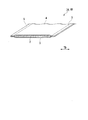
- FIG. 1 is a partially cutaway perspective view showing an example of a laminated film having a curable resin layer.
- a photocurable resin laminated film (laminated film 1B) using a photocurable resin as an example of the curable resin has a film-shaped photocurable resin layer 2 made of a liquid photocurable resin composition as a pair of base materials.
- a film, that is, a photocurable resin layer 2 of a laminated film 1A sandwiched between a first base film (base film) 3 and a second base film (cover film) 4 is cured.
- the photocurable resin layer 2 before photocuring is the laminated film 1A
- the photocurable resin layer 2 after being photocured is the laminated film 1B
- the photocurable resin layer 2 after being photocured is the photocurable resin. This is referred to as film 2B.
- the width dimensions of the first base film 3 and the second base film 4 are set to be larger than that of the photocurable resin layer 2, and the photocurable resin layer 2 includes the first base film 3 and the second base film 3. 2 It is not formed between both ends of the base film 4 in the width direction TD. That is, both ends in the width direction TD of the laminated film 1A of the present embodiment are the ears 5 in which only the first base film 3 and the second base film 4 are laminated. Note that the ears 5 may not be provided in particular.
- the photocurable resin composition in the present embodiment is preferably a compound having a plurality of photopolymerizable carbon-carbon double bonds.
- the photocurable resin composition (1) allyl ester resin, (2) vinyl ester resin, (3) polyfunctional urethane (meth) acrylate resin, (4) cage-type siloxane- (meth) acrylate resin Compositions, and the like.
- the allyl ester resin contains a polyvalent allyl ester compound as a main component and may further contain a radical polymerizable compound.
- the polyvalent allyl ester compound can be produced by a transesterification reaction between an allyl ester monomer of a polyvalent carboxylic acid and a polyhydric alcohol having 2 to 6 hydroxyl groups and 2 to 20 carbon atoms.
- allyl ester monomer of polyvalent carboxylic acid examples include diallyl phthalate, diallyl isophthalate, diallyl terephthalate, diallyl 2,6-naphthalenedicarboxylic acid, diallyl 1,2-cyclohexanedicarboxylic acid, and 1,3-cyclohexanedicarboxylic acid.
- Two or more kinds of these allyl ester monomers may be used if necessary, and the allyl ester monomers are not limited to the above specific examples.
- examples of the divalent alcohol include ethylene glycol, propylene glycol, 1,3-propanediol, 1,3-butanediol, 1,4-butanediol and neo.
- Pentyl glycol hexamethylene glycol, 1,4-cyclohexanedimethanol, 2-methyl-1,3-propanediol, 3-methyl-1,5-pentanediol, diethylene glycol, dipropylene glycol, triethylene glycol, polyethylene glycol, Examples thereof include bisphenol-A ethylene oxide adducts, bisphenol-A propylene oxide adducts, and 2,2- [4- (2-hydroxyethoxy) -3,5-dibromophenyl] propane.
- trihydric or higher polyhydric alcohols include glycerin, trimethylolpropane, trimethylolethane, pentaerythritol, dipentalithritol and the like. It may be a mixture of two or more of these polyhydric alcohols. Further, the present invention is not limited to the above specific example.
- the polyvalent allyl ester compound is radically polymerizable and can be polymerized by heat, ultraviolet rays, electron beams, etc. It can also be copolymerized with other radically polymerizable compounds.
- the radical polymerizable compound to be copolymerized with the polyvalent allyl ester compound is not particularly limited as long as it is a compound which is copolymerized with the polyvalent allyl ester compound.
- Specific examples thereof include diallyl phthalate, diallyl isophthalate, diallyl terephthalate, allyl benzoate, allyl ⁇ -naphthoate, allyl ⁇ -naphthoate, allyl 2-phenylbenzoate, allyl 3-phenylbenzoate, and 4-phenylbenzoic acid.
- Examples of the vinyl ester resin include those obtained by substituting the allyl group of the polyvalent allyl ester compound with a vinyl group.
- the polyfunctional urethane (meth) acrylate resin is obtained by reacting a polyisocyanate compound and a hydroxyl group-containing (meth) acrylate compound with a catalyst such as dibutyltin dilaurate, if necessary.
- a catalyst such as dibutyltin dilaurate
- the polyisocyanate-based compound include isophorone diisocyanate, tricyclodecane diisocyanate, norbornene diisocyanate, 1,3-diisocyanatocyclohexane, 1,4-diisocyanatocyclohexane, hydrogenated xylylene diisocyanate, hydrogenated diphenylmethane diisocyanate, and the like.
- Illustrative examples include isocyanate compounds.
- Specific examples of the hydroxyl group-containing (meth) acrylate compound include, for example, 2-hydroxyethyl (meth) acrylate, 2-hydroxypropyl (meth) acrylate, 2-hydroxybutyl (meth) acrylate, and 2-hydroxy-3- ( Examples thereof include (meth) acryloyloxypropyl (meth) acrylate, pentaerythritol tri (meth) acrylate, dipentaerythritol penta (meth) acrylate, dipentaerythritol tetra (meth) acrylate, and dipentaerythritol tri (meth) acrylate.
- cage-type siloxane- (meth) acrylate resin composition examples include the resin composition described in JP 2010-195986 A.
- thermosetting resins for example, thermosetting resins and electron beam curable resins.
- curable resin which is cured by the irradiation of (1).
- the first base film 3 and the second base film 4 are films made of a light transmissive resin that can transmit active energy rays for curing the photocurable resin layer 2, specifically, ultraviolet rays and light. ..
- Specific examples of the material of the first base film 3 and the second base film 4 include polyethylene terephthalate (PET), polypropylene, polyethylene and the like.
- the constituent materials of the first base film 3 and the second base film 4 may be the same as or different from each other. Further, the first base material film 3 and the second base material film 4 have functional layers such as a hard coat layer and an antireflection layer which are transferred to the photocurable resin film after the photocurable resin layer 2 is cured. Further, it may be formed.
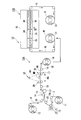
- FIG. 2 is a configuration diagram illustrating a cured resin film manufacturing apparatus according to the first embodiment.
- the photocurable resin film manufacturing apparatus (cured resin film manufacturing apparatus) 10 includes a first processed portion 10A for forming the laminated film 1B and a second processed portion (heating portion) for heating the laminated film 1B to further increase hardness. ) 10B.
- the first processing unit 10A of the photocurable resin film manufacturing apparatus 10 includes a base material roll 11 (first base material film supply means), a base material roll 12 (second base material film supply means) 12, a coating section (resin).
- a layer forming unit 13, a laminating unit (adhesion unit) 14, an active energy ray irradiation unit 15, and a winding roll 16 are provided.
- the base material roll (first base material film supply means) 11 is formed by winding the first base material film 3.
- the base material roll (second base material film supply means) 12 is formed by winding the second base material film 4.
- the coating part (resin layer forming means) 13 is made of a photocurable resin composition by applying a liquid photocurable resin composition onto the first base material film 3 fed from the base material roll 11.
- the film-shaped photocurable resin layer 2 (see FIG. 1) is formed.
- the coating unit 13 is driven by a motor (not shown) to rotate to transfer the first base material film 3 in the longitudinal direction thereof, and the first base material film 3 wound around the outer peripheral surface of the backup roll 21.
- a slit die 22 for coating the photocurable resin composition is provided on the top.
- the transfer speed of the first base material film 3, the second base material film 4, the laminated film 1A and the laminated film 1B in the first processing portion 10A is set based on the rotation speed of the backup roll 21. Has been done.
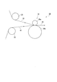
- FIG. 3 is a main part enlarged configuration diagram showing the laminating part (contact means) and its vicinity.
- the laminating section (adhesion means) 14 is provided between the first base material film 3 that has passed through the coating section 13 and the second base material film 4 that has been fed from the other base material roll 12, and the photocurable resin layer 2 And the both ends in the width direction TD (see FIG. 1) are tightly adhered to each other by the ears 5 (see FIG. 1) which are both ends of the first base film 3 and the second base film 4 to form a laminated film. 1A.
- the laminating section (contact means) 14 is composed of one laminating roll 14a.
- the laminating roll 14a includes a feed roll 25 arranged on the base roll 11 side and a feed roll 26 arranged on the base roll 12 side of the front stage, and a drive roll 27 contacting the first base film 3 on the rear stage side. Between the first base film 4 and the second base film 4.
- the laminating roll 14a is pressed only on the front surface side of the second base material film 4, and both end portions of the first base material film 3 and the second base material film 4 are subjected to air lamination. To adhere.
- the laminating portion (contact means) 14 is not provided with a roller or the like that contacts the first base material film 3.
- the first base film 3 and the second base film 4 sandwiching the photocurable resin layer 2 are stressed by the laminating roll 14a from the second base film 4 side.
- the laminating roll 14a that constitutes the laminating unit (contact means) 14 is formed such that its roll diameter ⁇ 1 is smaller than the roll diameter ⁇ 2 of the drive roll 27 arranged on the subsequent stage side.
- the roll diameter ⁇ 1 of the laminating roll 14a is, for example, in the range of 5 mm or more and 100 mm or less.
- the laminating unit (adhesion means) 14 by pressing the laminating roll 14a only on the first base material film 3 of the first base material film 3 and the second base material film 4 that are adhered to each other, the conventional Even when the circularity and bearing accuracy of the laminating roll 14a are not so high as compared with the structure in which the two base films are sandwiched between the two rolls from both sides as described above, the formed photocurable resin The variation in the thickness of the layer 2 can be effectively suppressed.
- the roll diameter ⁇ 1 of the laminating roll 14a smaller than the roll diameter ⁇ 2 of the drive roll 27 disposed on the rear side, or specifically, by setting the roll diameter ⁇ 1 to, for example, 5 mm or more and 50 mm or less, the first base The amount of air entrained between the material film 3 and the second base material film 4 can be reduced, and the photocurable resin layer 2 with few bubbles can be formed.
- the self-weight deflection amount of the laminating roll 14a is preferably 40 ⁇ m or less, and more preferably 20 ⁇ m or less.
- the self-weight deflection amount is 40 ⁇ m or less, the variation in the thickness of the photocurable resin layer 2 in the width direction TD can be reduced.
- the deflection amount due to its own weight is the difference in height between the end portion and the central portion of the laminating roll 14a caused by hanging down due to its own weight as shown in FIG. If this difference is large (the amount of deflection due to its own weight is large), the difference in thickness between the central portion and the end portion of the photocurable resin layer 2 in the width direction TD tends to increase.
- the amount of self-weight deflection can be reduced by increasing the rigidity of the laminating roll 14a, reducing the weight, and using a material with a high elastic modulus.
- the laminating roll 14a is made of solid stainless steel or the like, the rigidity can be increased by increasing its diameter, and as a result, the amount of self-weight deflection can be reduced.
- the diameter of the laminating roll 14a becomes too thick, the laminating roll 14a may become too heavy and, on the contrary, the deflection may increase, so that there is an appropriate region.
- the laminating roll 14a may be made into a hollow cylinder to reduce the weight. In this case, the required rigidity is secured.
- the roll diameter ⁇ 1 of the laminating roll 14a is more preferably 20 to 40 mm, further preferably 25 to 35 mm, from the viewpoint of reducing the amount of entrained air. From the viewpoint of effectively suppressing the variation in the width direction TD thickness of the photocurable resin layer 2, 30 to 100 mm is preferable. Considering the balance of both effects, 30 to 50 mm is preferable.
- the roll diameter ⁇ 2 of the drive roll 27 is preferably 100 to 500 mm, more preferably 150 to 250 mm.
- the laminating roll 14a is arranged so as to contact only the first base material film 3 which is the cover film, but conversely, only the second base material film 4 which is the base film is arranged.
- the structure may be in contact with.
- two or more laminating rolls 14a can be arranged side by side so as to contact only either the first base film 3 or the second base film 4.
- the active energy ray irradiation unit 15 activates the laminated film 1A formed in the laminating unit (adhesion means) 14 from the side of the second base film 4 constituting the laminated film 1A.
- the laminated film 1B is obtained.
- the active energy ray R1 is an energy ray that cures the curable resin composition, and examples thereof include ultraviolet rays, visible rays, electron rays, and heat rays.
- the active energy ray irradiation unit 15 is arranged downstream of the laminating unit 14 in the transport direction MD of the laminated film 1A. Specific examples of the active energy ray irradiation unit 15 include those by arc discharge such as metal halide lamps, xenon lamps, black lights, and mercury lamps, glow discharge such as neon lamps, those by electron beam generators, and infrared lamps. ..
- the photocurable resin layer 2 is formed by using the photocurable resin composition that is cured by ultraviolet rays, so that an ultraviolet lamp is used as the active energy ray irradiation unit 15. I am using.
- the base film on the side irradiated with such energy rays which is the second base film 4 in the present embodiment, is formed of a material that can transmit the energy rays to be irradiated with high efficiency, thereby irradiating active energy rays with a small output. Even in the portion 15, the photocurable resin layer 2 can be efficiently cured.
- the tension applying means 17 applies a tension to the laminated film 1A to be transferred.
- the active energy ray irradiation unit 15 irradiates the laminated film 1A with the active energy ray R1 while the tension is applied to the laminated film 1A by the tension applying means 17.
- the irradiation region RA of the active energy ray R1 by the active energy ray irradiation unit 15 is set between the pinch rolls 30, 30 adjacent to each other in the transport direction MD of the laminated film 1A.
- the laminated film 1A (1B) is supported by the support rolls 18 and 19 on the upstream side and the downstream side of the tension applying means 17 in the transport direction MD of the laminated film 1A, respectively.
- the take-up roll 16 is driven and rotated by a motor (not shown) or the like to wind up the laminated film 1B after passing through the active energy ray irradiation section 15.
- the rotation speed of the winding roll 16 is set so that excessive tension is not applied in the longitudinal direction of the laminated film 1A (1B) transferred from the coating unit 13 toward the winding roll 16, and from the coating unit 13. It is set based on the rotation speed of the backup roll 21 and the output data of the tension detector (not shown) so that the laminated film 1A transported toward the winding roll 16 does not sag.
- the backup roll 21 and the take-up roll 16 form a transfer unit that transfers the laminated film 1A (1B) in the longitudinal direction thereof.
- the second processed portion 10B irradiates the laminated film 1B with far infrared rays and heats the laminated film 1B while transferring the laminated film 1B in the longitudinal direction thereof, whereby the photocurable resin layer 2 is further cured and the heat-cured photocuring is performed.
- the resin film 1C is formed.
- the second processing unit 10B is a supply roll 31 that supplies the laminated film 1B obtained in the first processing unit 10A, a heating furnace 32 that heats the laminated film 1B, and a winding roll that winds the heated photocurable resin film 1C. 33 is provided.
- the heating furnace 32 is, for example, a continuous heating furnace, and includes a furnace body 34 into which the laminated film 1B is introduced, and one or a plurality of transfer rollers for transferring the laminated film 1B in the furnace body 34 along the transfer direction D1. 35 and one or a plurality of far-infrared heaters 36 for heating the laminated film 1B in the furnace body 34.
- the photocurable resin film 1C After heating in which the photocurable resin layer 2 is further cured and the strength is improved is obtained. be able to.
- the inside of the heating furnace 32 may be an air atmosphere or an inert gas atmosphere, for example, a nitrogen gas atmosphere.
- a nitrogen gas atmosphere When the nitrogen gas atmosphere is used, it is possible to prevent the polymerization reaction of the photocurable resin layer 2 from becoming insufficient due to consumption of the polymerization initiator in the photocurable resin layer 2 by contact with air.
- FIG. 4 is an enlarged perspective view of essential parts showing a laminating section (adhesion means) and its vicinity in the apparatus for producing a cured resin film of the second embodiment.
- the rolls provided on the rear side of the laminating unit (adhesion means) 14 are different from those of the first embodiment.
- the other parts are the same as those in the first embodiment.
- a drive roll 47 is arranged on the rear side of one laminating roll 14a that constitutes the laminating unit (contact means) 14 of the cured resin film manufacturing apparatus 40.
- a nip roll 48 is arranged so as to face the drive roll 47.
- the nip roll 48 has a cylindrical roll main body 48a having a uniform diameter as a whole, and an enlarged diameter portion 48b formed on both sides of the roll main body 48a and having a diameter larger than the diameter of the roll main body 48a. ..
- the expanded diameter portion 48b of the nip roll 48 may be, for example, one in which rubber rings having a predetermined width are fitted on both sides of the roll body 48a.
- the roll body 48a may be integrally formed of the same material.
- the first base film 3 and the second base film 4 are in direct contact with each other, which is a peripheral region in the width direction TD of the laminated film 1A, without the photocurable resin layer 2 being formed. It is formed at a position where it abuts on the ear 5.
- a gap corresponding to the difference between the radius of the roll body 48a and the radius of the expanded diameter portion 48b is formed between the two expanded diameter portions 48b in the portion where the drive roll 47 and the nip roll 48 face each other.
- Such a gap may be larger than the thickness of the portion of the laminated film 1 ⁇ / b> A where the photocurable resin layer 2 is formed inside the ear portion 5 for example.
- the nip roll 48 when the laminated film 1A formed in the laminating unit 14 is transported by the drive roll 47, the nip roll 48 is laminated with the expanded diameter portion 48b. The nip roll 48 does not come into contact with the portion where the photo-curable resin layer 2 is formed, and only comes into contact with the ear portion 5 of 1A.
- the tension of the laminated film 1A in the laminating unit 14 on the upstream side does not become unstable. Therefore, even if the tension of the laminated film 1A changes on the downstream side of the laminating unit 14, the laminating unit 14 is not affected and the laminated film 1A can be stably and accurately formed.
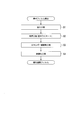
- FIG. 5 is a flowchart showing stepwise an example of a method for producing a cured resin film.
- the belt-shaped first base material film 3, the second base material film 4, the laminated film 1A, the laminated film 1B, and the photocurable resin film 1C are transferred in the longitudinal direction by a transfer means. While done.
- a liquid photocurable resin is applied onto the first base material film 3 fed from the base material roll 11.
- the composition is applied to form the photocurable resin layer 2 (application step S1).
- the photocurable resin layer 2 is provided between the first base film 3 that has passed through the coating section 13 and the second base film 4 that has been fed from the base roll 12 in the laminating section (adhesion means) 14.
- the first base film 3 and the second base film 4 are brought into close contact with each other by being sandwiched and the laminate roll 14a to obtain a laminated film 1A (adhesion step S2).
- one laminating roll 14a is brought into contact only with the surface of the second base film 4, and the first base film 3 and the second base film 4 are sandwiched with the photocurable resin layer 2 by air lamination. And close contact.
- the transferred laminated film 1A is irradiated with the active energy ray R1 of the active energy ray irradiation unit 15 to cure the photocurable resin layer 2 (energy ray irradiation step S3).
- the photocurable resin layer 2 is cured to form the laminated film 1B.
- the laminated film 1B is wound up by the winding roll 16.
- the laminated film 1B is introduced from the supply roll 31 into the furnace body 34.
- the laminated film 1B is transferred by the transfer roller 35 between the far-infrared heaters 36, 36 arranged facing each other (thermosetting step S4).
- the method for producing a cured resin film of the embodiment only the first base material film 3 of the first base material film 3 and the second base material film 4 that are in close contact with each other is laminated in the contacting step.
- the circularity and the bearing accuracy of the laminating roll 14a are not so high as compared with the conventional structure in which two base film are sandwiched between two rolls by pressing 14a against each other.
- the variation in the thickness of the formed laminated film 1A can be effectively suppressed. This makes it possible to obtain a laminated film 1A having a uniform thickness with little thickness variation, and a laminated film 1B obtained by curing the photocurable resin layer 2.
- the laminated film 1A is wound by the winding roll 16 immediately after the laminated film 1A is irradiated with the active energy ray R1, but the present invention is not limited to this.
- the thermosetting step S4 can be performed by directly introducing the second processing unit 10B.
- both ends (ears 5) in the width direction TD of the laminated film 1A formed in each embodiment are configured by laminating only the first base film 3 and the second base film 4,
- Example 1 In Example 1 of the present invention, 80 parts by mass of an allyl ester resin prepared by transesterification of diallyl 1,4-cyclohexanedicarboxylate and trimethylolpropane was added to trimethylolpropane triacrylate (manufactured by Toagosei Co., Ltd.
- phosphine oxide (registered trademark) TPO” manufactured by IGM Resins)
- the obtained photocurable resin composition was put into a coating device, and after being cured onto a first base film (polyethylene terephthalate biaxially stretched film, width 750 mm, thickness 100 ⁇ m) unrolled at 4 m / min. Was applied using a slit die 22 so that the thickness of the film was about 200 ⁇ m.
- a laminating roll 14a having a diameter of 30 mm was pressed against the upper surface of the second base film (the same as the first base film) and laminated to form a laminated film 1A, and then 200 mW /
- the laminated film 1B was wound into a roll by continuously irradiating ultraviolet rays under the conditions of cm 2 and 800 mJ / cm 2 .
- the drive roll 27 has a diameter of 200 mm.
- This roll-shaped laminated film 1B is heat-treated while being continuously unrolled in a far infrared heating furnace set at 150 ° C. so that the residence time is 10 minutes, and the photocured resin 1C after thermosetting is wound into a roll. It was After peeling the first and second substrate films from the photocurable resin film 1C after thermosetting, the thickness of the photocurable resin film 1C in the transport direction MD was measured. Digimicro MF-501 (manufactured by Nikon Corporation) was used for thickness measurement, and the range of length 1600 mm was measured at 20 mm intervals.
- Comparative Example 1 As a conventional comparative example 1, a conventional apparatus 30 for manufacturing a cured resin film shown in FIG. 6 was used.
- the laminating unit (adhesion means) 34 of the conventional cured resin film manufacturing apparatus 30 adheres the first base material film 43 and the second base material film 44 in which the photocurable resin layer is sandwiched.
- the laminating unit 34 is configured by a pair of laminating rolls 35a and 35b, and the laminating rolls 35a and 35b are pressed against the front surface side of the first base film 43 and the front surface side of the second base film 44, respectively.
- the first base film 43 and the second base film 44 pass between the two laminating rolls 35a and 35b to form the laminated film 2A.
- the configuration other than the laminating section (contact means) 34 is the same as that of the embodiment of the present invention shown in FIG.
- the upper laminating roll 35a had a diameter of 130 mm
- the lower laminating roll (driving roll) 35b had a diameter of 200 mm.
- the variation width of the obtained cured resin film is about 2 ⁇ m, and the standard deviation is about 0.41. It was confirmed that a highly accurate cured resin film with little thickness variation over the entire measurement length can be obtained.
- the obtained cured resin film has a large fluctuation range of about 8 ⁇ m and a standard deviation of about 2.56, and the thickness is periodically increased and decreased. Only a cured resin film with low thickness accuracy was obtained. Therefore, the effect of the apparatus and method for producing a cured resin film of the present invention was confirmed.
- Example 2 A photocurable resin film 1C was produced in the same manner as in Example 1.
- the diameter of the laminating roll 14a is 30 mm, and the self-weight deflection amount is 40 ⁇ m.
- the thickness of the photocurable resin film 1C in the transport direction MD and the central portion and both end portions in the width direction TD (L side, R side) ) was measured.
- Digimicro MF-501 manufactured by Nikon Corporation was used for thickness measurement.
- Regarding the transfer direction MD a range of 600 mm in length was measured at 20 mm intervals.
- the central portion and the portions (L side and R side) 280 mm apart from each other on the left and right sides were measured (see FIG. 9).
- Example 3 A photocurable resin film 1C was manufactured in the same manner as in Example 2 except that the diameter of the laminating roll 14a was changed to 50 mm, and the same measurement was performed. The amount of self-weight deflection of the laminating roll 14a is 15 ⁇ m.
- Comparative example 2 A photocurable resin film 1C was produced in the same manner as in Comparative Example 1, and the same measurement as in Example 2 was performed.
- the diameter of the laminating roll 35a is 130 mm.
- the amount of deflection of the laminating roll 35a due to its own weight is 3 ⁇ m.
- Example 2 The measurement results of Example 2, Example 3, and Comparative Example 2 are shown in Table 2 and FIG.
- the thickness in the transfer direction MD changes greatly periodically.
- the difference between the center of the standard deviation of the thickness in the width direction TD and the L side and the R side is also large.
- the variation (standard deviation) in the thickness in the transport direction MD is small.
- Example 2 it can be seen that the difference between the center of the standard deviation of the thickness in the width direction TD and the L side and the R side is further improved.
Landscapes
- Health & Medical Sciences (AREA)
- Engineering & Computer Science (AREA)
- Manufacturing & Machinery (AREA)
- Toxicology (AREA)
- Physics & Mathematics (AREA)
- Oral & Maxillofacial Surgery (AREA)
- Thermal Sciences (AREA)
- Laminated Bodies (AREA)
- Lining Or Joining Of Plastics Or The Like (AREA)
Abstract
簡易な構成で、積層フィルムの周期的な厚み変動を抑制する。第1基材フィルムを供給する第1基材フィルム供給手段と、第2基材フィルムを供給する第2基材フィルム供給手段と、前記第1基材フィルムまたは前記第2基材フィルムに硬化性樹脂層を形成する樹脂層形成手段と、前記第1基材フィルムと前記第2基材フィルムとを前記硬化性樹脂層を挟んで密着させて積層フィルムを形成する密着手段と、を少なくとも備え、前記密着手段は、前記第1基材フィルムまたは前記第2基材フィルムのうち、いずれか一方の表面だけに接するラミネートロールをからなることを特徴とする。
Description
この発明は、硬化樹脂フィルムの製造装置及び製造方法に関する。
本願は、2018年11月19日に日本に出願された特願2018-216360号に基づき優先権を主張し、その内容をここに援用する。
本願は、2018年11月19日に日本に出願された特願2018-216360号に基づき優先権を主張し、その内容をここに援用する。
従来、硬化性樹脂、例えば光の照射によって硬化する光硬化性樹脂を含むフィルム(光硬化性樹脂フィルム)の硬化物(硬化樹脂フィルム)を製造する場合には、例えば特許文献1のように、液状の光硬化性樹脂組成物を透明な基材フィルム上に薄膜状(フィルム状)に塗工し、その上から透明なカバーフィルムを積層した積層フィルムを構成する。更にこの積層フィルムに紫外線を照射して薄膜状の光硬化性樹脂組成物を硬化させる手法が用いられている(例えば、特許文献1を参照)。
従来、こうした積層フィルムを形成する過程で、光硬化性樹脂組成物を挟んで一方の基材フィルムに他方の基材フィルムを密着させる際には、互いに対向して配された2つのラミネートロールどうしの間に光硬化性樹脂組成物を挟んだ一組の基材フィルムを通過させることによって行われていた(例えば、特許文献2を参照)。
従来、こうした積層フィルムを形成する過程で、光硬化性樹脂組成物を挟んで一方の基材フィルムに他方の基材フィルムを密着させる際には、互いに対向して配された2つのラミネートロールどうしの間に光硬化性樹脂組成物を挟んだ一組の基材フィルムを通過させることによって行われていた(例えば、特許文献2を参照)。
上述した特許文献2のように一組の基材フィルムを密着させると、得られた積層フィルムは延長方向に対して周期的に厚みの変動が大きくなることがあった。これは、ラミネートロールの真円度や、ラミネートロールの回転軸の軸受精度が高くないことによって生じる。しかしながら、こうしたラミネートロールの真円度や軸受精度の向上には限界があり、より簡易な方法で積層フィルムの周期的な厚み変動を抑制することが望まれている。
本発明は、上述した事情に鑑みたものであって、簡易な構成で、積層フィルムの周期的な厚み変動を抑制できる硬化樹脂フィルムの製造装置およびこれを用いた硬化樹脂フィルムの製造方法を提供することを目的とする。
この課題を解決するために、本発明に係る硬化樹脂フィルムの製造装置は、液状の硬化性樹脂組成物からなるフィルム状の硬化性樹脂層を第1基材フィルムおよび第2基材フィルムの間に挟み込んでなる帯状の積層フィルムを長手方向に移送しながら、前記積層フィルムに活性エネルギー線を照射して前記硬化性樹脂層を硬化させて連続的に硬化樹脂フィルムを得る硬化樹脂フィルムの製造装置であって、前記第1基材フィルムを供給する第1基材フィルム供給手段と、前記第2基材フィルムを供給する第2基材フィルム供給手段と、前記第1基材フィルムまたは前記第2基材フィルムに前記硬化性樹脂層を形成する樹脂層形成手段と、前記第1基材フィルムと前記第2基材フィルムとを前記硬化性樹脂層を挟んで密着させて積層フィルムを形成する密着手段と、を少なくとも備え、前記密着手段は、前記第1基材フィルムまたは前記第2基材フィルムのうち、いずれか一方の表面だけに接するラミネートロールからなることを特徴とする。
本発明によれば、互いに密着させる第1基材フィルムおよび第2基材フィルムのいずれか一方だけにラミネートロールを押し当てることによって、従来のように2つの基材フィルムを両側から2つのロールの間で挟み込む構造と比較して、ラミネートロールの真円度や軸受精度がそれほど高くない場合であっても、形成した積層フィルムの厚みの変動を効果的に抑制することができる。これにより、厚み変動の少ない均一な厚みの積層フィルム、および硬化性樹脂層を硬化させた硬化樹脂フィルムを得ることが可能になる。
また、本発明では、前記ラミネートロールの後段側には、前記積層フィルムを移送する駆動ロールが形成されており、前記ラミネートロールは、前記駆動ロールよりも直径が小さくてもよい。
また、前記ラミネートロールの自重たわみ量が40μm以下であることが好ましい。
また、前記ラミネートロールの自重たわみ量が40μm以下であることが好ましい。
また、本発明では、前記ラミネートロールの直径は、5mm以上、100mm以下の範囲であればよく、30mm以上、50mm以下の範囲が好ましい。
また、本発明では、前記積層フィルムを介して前記駆動ロールに対向するニップロールが形成され、前記ニップロールは、前記積層フィルムに対して所定の隙間を保って配されるロール本体と、該ロール本体の両側に形成され、前記積層フィルムの幅方向の周縁領域に接する拡径部とを有していてもよい。
また、本発明では、前記拡径部は、前記積層フィルムの幅方向のうち、前記硬化性樹脂層が形成された領域よりも外側に接していてもよい。
また、本発明では、前記硬化性樹脂組成物は、透明な光硬化性樹脂組成物であってもよい。
また、本発明では、前記透明な光硬化性樹脂組成物は、光重合性の炭素-炭素二重結合を複数個有する化合物であってもよい。
本発明の硬化樹脂フィルムの製造方法は、前記各項記載の硬化樹脂フィルムの製造装置を用いた硬化樹脂フィルムの製造方法であって、前記硬化性樹脂層を挟んで前記第1基材フィルムと前記第2基材フィルムとを密着させる密着工程を有し、前記密着工程では、前記第1基材フィルムまたは前記第2基材フィルムのうち、いずれか一方の表面だけに前記ラミネートロールを接触させつつ前記積層フィルムを移送することを特徴とする。
本発明によれば、簡易な構成で、積層フィルムの周期的な厚み変動を抑制できる硬化樹脂フィルムの製造装置およびこれを用いた硬化樹脂フィルムの製造方法を提供することができる。
最初に、実施形態の硬化樹脂フィルムの製造装置によって製造される硬化樹脂フィルムの一例について説明する。
図1は、硬化性樹脂層を有する積層フィルムの一例を示す一部破断斜視図である。
硬化性樹脂の一例として光硬化性樹脂を用いた光硬化性樹脂積層フィルム(積層フィルム1B)は、液状の光硬化性樹脂組成物からなるフィルム状の光硬化性樹脂層2を一対の基材フィルム、即ち第1基材フィルム(ベースフィルム)3および第2基材フィルム(カバーフィルム)4で挟み込んでなる積層フィルム1Aの光硬化性樹脂層2を硬化させたものである。以下の説明では、光硬化性樹脂層2を光硬化させる前のものを積層フィルム1A、光硬化させた後のものを積層フィルム1B、光硬化性樹脂層2が光硬化したものを光硬化樹脂フィルム2Bと称する。
図1は、硬化性樹脂層を有する積層フィルムの一例を示す一部破断斜視図である。
硬化性樹脂の一例として光硬化性樹脂を用いた光硬化性樹脂積層フィルム(積層フィルム1B)は、液状の光硬化性樹脂組成物からなるフィルム状の光硬化性樹脂層2を一対の基材フィルム、即ち第1基材フィルム(ベースフィルム)3および第2基材フィルム(カバーフィルム)4で挟み込んでなる積層フィルム1Aの光硬化性樹脂層2を硬化させたものである。以下の説明では、光硬化性樹脂層2を光硬化させる前のものを積層フィルム1A、光硬化させた後のものを積層フィルム1B、光硬化性樹脂層2が光硬化したものを光硬化樹脂フィルム2Bと称する。
本実施形態では、第1基材フィルム3および第2基材フィルム4の幅寸法が、光硬化性樹脂層2よりも大きく設定され、光硬化性樹脂層2は第1基材フィルム3および第2基材フィルム4の幅方向TDの両端部の間に形成されていない。即ち、本実施形態の積層フィルム1Aの幅方向TDの両端部は、第1基材フィルム3および第2基材フィルム4のみを積層した耳部5となっている。なお耳部5は特に設けなくてもよい。
本実施形態における光硬化性樹脂組成物としては、光重合性の炭素-炭素二重結合を複数個有する化合物が好ましい。光硬化性樹脂組成物を例示するならば、(1)アリルエステル樹脂、(2)ビニルエステル樹脂、(3)多官能ウレタン(メタ)アクリレート樹脂、(4)籠型シロキサン-(メタ)アクリレート樹脂組成物、などが挙げられる。
(1)アリルエステル樹脂は多価アリルエステル化合物を主成分とし、他にラジカル重合性化合物を含んでもよい。多価アリルエステル化合物は、多価カルボン酸のアリルエステルモノマーと2~6個の水酸基を有する炭素数2~20の多価アルコールとのエステル交換反応により製造することができる。多価カルボン酸のアリルエステルモノマーの具体例としては、フタル酸ジアリル、イソフタル酸ジアリル、テレフタル酸ジアリル、2,6-ナフタレンジカルボン酸ジアリル、1,2-シクロヘキサンジカルボン酸ジアリル、1,3-シクロヘキサンジカルボン酸ジアリル、1,4-シクロヘキサンジカルボン酸ジアリル、エンドメチレンテトラヒドロフタル酸ジアリル、メチルテトラヒドロフタル酸ジアリル、アジピン酸ジアリル、コハク酸ジアリル、マレイン酸ジアリル等が挙げられる。これらアリルエステルモノマーは、必要に応じて2種以上使用することもでき、また、上述の具体例に限定されるものではない。
炭素数2~20の多価アルコールの具体例のうち、2価のアルコールとしては、エチレングリコール、プロピレングリコール、1,3-プロパンジオール、1,3-ブタンジオール、1,4-ブタンジオール、ネオペンチルグリコール、ヘキサメチレングリコール、1,4-シクロヘキサンジメタノール、2-メチル-1,3-プロパンジオール、3-メチル-1,5-ペンタンジオール、ジエチレングリコール、ジプロピレングリコール、トリエチレングリコール、ポリエチレングリコール、ビスフェノール-Aのエチレンオキサイド付加物、ビスフェノール-Aのプロピレンオキサイド付加物、2,2-[4-(2-ヒドロキシエトキシ)-3,5-ジブロモフェニル]プロパン等が挙げられる。
また、3価以上の多価アルコールの具体例としては、グリセリン、トリメチロールプロパン、トリメチロールエタン、ペンタエリスリトール、ジペンタリスリトール等が挙げられる。これらの多価アルコールの2種以上の混合物であってもよい。また、上述の具体例に限定されるものではない。
さらに、多価アリルエステル化合物はラジカル重合性であり、熱や紫外線、電子線等により重合させることができる。また、他のラジカル重合性化合物と共重合することもできる。
多価アリルエステル化合物と共重合させるラジカル重合性化合物は、多価アリルエステル化合物と共重合する化合物であれば特に制限はない。その具体例としては、ジアリルフタレート、ジアリルイソフタレート、ジアリルテレフタレート、アリルベンゾエート、α-ナフトエ酸アリル、β-ナフトエ酸アリル、2-フェニル安息香酸アリル、3-フェニル安息香酸アリル、4-フェニル安息香酸アリル、o-クロロ安息香酸アリル、m-クロロ安息香酸アリル、p-クロロ安息香酸アリル、o-ブロモ安息香酸アリル、m-ブロモ安息香酸アリル、p-ブロモ安息香酸アリル、2,6-ジクロロ安息香酸アリル、2,4-ジクロロ安息香酸アリル、2,4,6-トリブロモ安息香酸アリル、1,4-シクロヘキサンジカルボン酸ジアリル、1,3-シクロヘキサンジカルボン酸ジアリル、1,2-シクロヘキサンジカルボン酸ジアリル、1-シクロヘキセン-1,2-ジカルボン酸ジアリル、3-メチル-1,2-シクロヘキサンジカルボン酸ジアリル、4-メチル-1,2-シクロヘキサンジカルボン酸ジアリル、エンディック酸ジアリル、クロレンド酸ジアリル、3,6-メチレン-1,2-シクロヘキサンジカルボン酸ジアリル、トリメリット酸トリアリル、ピロメリット酸テトラアリル、ジフェン酸ジアリル等、コハク酸ジアリル、アジピン酸ジアリル等のアリルエステル類、ジベンジルマレート、ジベンジルフマレート、ジフェニルマレート、ジフェニルフマレート、ジブチルマレート、ジブチルフマレート、ジメトキエチルマレート、ジメトキシエチルフマレート等のマレイン酸ジエステル/フマル酸ジエステル類、メチル(メタ)アクリレート、エチル(メタ)アクリレート、n-ブチル(メタ)アクリレート、i-ブチル(メタ)アクリレート、t-ブチル(メタ)アクリレート、2-エチルヘキシル(メタ)アクリレート、フェニル(メタ)アクリレート、ステアリル(メタ)アクリレート、ラウリル(メタ)アクリレート、ベンジル(メタ)アクリレート、イソボルニル(メタ)アクリレート、トリメチロールプロパントリ(メタ)アクリレート、エチレングリコールジ(メタ)アクリレート、1,4-ブタンジオールジ(メタ)アクリレート、1,6-ヘキサンジオールジ(メタ)アクリレート、1,9-ノナンジオールジ(メタ)アクリレート、ネオペンチルグリコールジ(メタ)アクリレート、ポリエチレンジリコールジ(メタ)アクリレート、ペンタエリスリトールテトラ(メタ)アクリレート、ジトリメチロールプロパンテトラ(メタ)アクリレート、ジペンタエリスリトールヘキサ(メタ)アクリレート、ジペンタエリスリトールペンタ(メタ)アクリレート、ジシクロペンタニル(メタ)アクリレート、ジシクロペンテニル(メタ)アクリレート、ジシクロペンテニルオキシエチル(メタ)アクリレート、トリシクロデカンジメタノールジ(メタ)アクリレート、ジシクロペンテニル(メタ)アクリレート、エトキシ化シクロヘキサンジメタノールジメタクリレート、アダマンチル(メタ)アクリレート等の(メタ)アクリル酸エステル類;スチレン、α-メチルスチレン、メトキシスチレン、ジビニルベンゼン等の芳香族ビニル化合物;酢酸ビニル、プロピオン酸ビニル、酪酸ビニル、ピバリン酸ビニル、ステアリン酸ビニル、カプロン酸ビニル等の脂肪族カルボン酸のビニルエステル;シクロヘキサンカルボン酸ビニルエステル等の脂環式ビニルエステル;安息香酸ビニルエステル、t-ブチル安息香酸ビニルエステル等の芳香族ビニルエステル、ジアリルカーボネート、ジエチレングリコールビスアリルカーボネート、PPG社製商品名CR-39に代表されるポリエチレングリコールビス(アリル)カーボネート樹脂等のアリルカーボネート化合物、分子内に反応性の異なる重合性二重結合を有する(メタ)アクリル酸アリル、(メタ)アクリル酸ビニルやマレイン酸ジアリル等の化合物、イソシアヌル酸トリアリルやシアヌル酸トリアリル等の窒素含有多官能アリル化合物、不飽和ポリエステル樹脂、ビニルエステル樹脂、ウレタンアクリレート、エポキシアクリレート等オリゴアクリレート類等が挙げられる。
(2)ビニルエステル樹脂としては前記多価アリルエステル化合物のアリル基をビニル基に置換したものが挙げられる。
(3)多官能ウレタン(メタ)アクリレート樹脂としては、ポリイソシアネート系化合物と水酸基含有(メタ)アクリレート系化合物を、必要に応じてジブチルチンジラウレートなどの触媒を用いて反応させて得られた物が挙げられる。ポリイソシアネート系化合物としてはイソホロンジイソシアネート、トリシクロデカンジイソシアネート、ノルボルネンジイソシアネート、1,3-ジイソシアナトシクロヘキサン、1,4-ジイソシアナトシクロヘキサン、水添化キシリレンジイソシアネート、水添化ジフェニルメタンジイソシアネートなどのポリイソシアネート系化合物などが例示される。水酸基含有(メタ)アクリレート系化合物の具体例としては、例えば、2-ヒドロキシエチル(メタ)アクリレート、2-ヒドロキシプロピル(メタ)アクリレート、2-ヒドロキシブチル(メタ)アクリレート、2-ヒドロキシ-3-(メタ)アクリロイロキシプロピル(メタ)アクリレート、ペンタエリスリトールトリ(メタ)アクリレート、ジペンタエリスリトールペンタ(メタ)アクリレート、ジペンタエリスリトールテトラ(メタ)アクリレート、ジペンタエリスリトールトリ(メタ)アクリレートなどが挙げられる。
(4)籠型シロキサン-(メタ)アクリレート樹脂組成物としては、特開2010-195986号公報に記載の樹脂組成物が挙げられる。
なお、本発明の硬化樹脂フィルムの製造には、上述した光硬化性樹脂を用いる以外にも、熱硬化性樹脂、電子線硬化性樹脂など、光以外のエネルギー線(例えば、熱線、電子線等)の照射により硬化する硬化性樹脂を用いることもできる。
第1基材フィルム3および第2基材フィルム4は、光硬化性樹脂層2を硬化させるための活性エネルギー線、具体的には紫外線や光を透過可能な光透過性樹脂からなるフィルムである。具体的な第1基材フィルム3および第2基材フィルム4の材料としては、例えばポリエチレンテレフタレート(PET)、ポリプロピレン、ポリエチレン等が挙げられる。
なお、これら第1基材フィルム3および第2基材フィルム4の構成材料は、互いに同じであっても異なっていてもよい。さらに、第1基材フィルム3および第2基材フィルム4には、光硬化性樹脂層2が硬化した後の光硬化樹脂フィルムに転写されるハードコート層や反射防止層などの機能性層が更に形成されていてもよい。
(硬化樹脂フィルムの製造装置:第1実施形態)
図2は、第1実施形態の硬化樹脂フィルムの製造装置を示す構成図である。
光硬化樹脂フィルムの製造装置(硬化樹脂フィルムの製造装置)10は、積層フィルム1Bを形成する第1加工部10Aと、この積層フィルム1Bを加熱して硬度を更に高める第2加工部(加熱部)10Bとを備えている。
光硬化樹脂フィルムの製造装置10の第1加工部10Aは、基材ロール11(第1基材フィルム供給手段)、基材ロール12(第2基材フィルム供給手段)12、塗工部(樹脂層形成手段)13、ラミネート部(密着手段)14、活性エネルギー線照射部15、巻取ロール16を備えている。
図2は、第1実施形態の硬化樹脂フィルムの製造装置を示す構成図である。
光硬化樹脂フィルムの製造装置(硬化樹脂フィルムの製造装置)10は、積層フィルム1Bを形成する第1加工部10Aと、この積層フィルム1Bを加熱して硬度を更に高める第2加工部(加熱部)10Bとを備えている。
光硬化樹脂フィルムの製造装置10の第1加工部10Aは、基材ロール11(第1基材フィルム供給手段)、基材ロール12(第2基材フィルム供給手段)12、塗工部(樹脂層形成手段)13、ラミネート部(密着手段)14、活性エネルギー線照射部15、巻取ロール16を備えている。
基材ロール(第1基材フィルム供給手段)11は第1基材フィルム3を巻きつけたものである。基材ロール(第2基材フィルム供給手段)12は第2基材フィルム4を巻きつけたものである。
塗工部(樹脂層形成手段)13は、基材ロール11から繰り出された第1基材フィルム3上に液状の光硬化性樹脂組成物を塗工して、光硬化性樹脂組成物からなるフィルム状の光硬化性樹脂層2(図1参照)を形成するものである。塗工部13は、不図示のモータにより駆動回転して第1基材フィルム3をその長手方向に移送するバックアップロール21と、バックアップロール21の外周面に掛け回された第1基材フィルム3上に、光硬化性樹脂組成物を塗工するスリットダイ22と、を備えている。
なお、本実施形態では、バックアップロール21の回転速度を基準にして、第1加工部10Aにおける第1基材フィルム3、第2基材フィルム4、積層フィルム1Aおよび積層フィルム1Bの移送速度が設定されている。
図3は、ラミネート部(密着手段)およびその近傍を示す要部拡大構成図である。
ラミネート部(密着手段)14は、塗工部13を通過した第1基材フィルム3と、他方の基材ロール12から繰り出された第2基材フィルム4との間で光硬化性樹脂層2を挟み込んで、幅方向TD(図1参照)の両端部は、第1基材フィルム3および第2基材フィルム4の両端部である耳部5(図1参照)で密着させて、積層フィルム1Aにするものである。
ラミネート部(密着手段)14は、塗工部13を通過した第1基材フィルム3と、他方の基材ロール12から繰り出された第2基材フィルム4との間で光硬化性樹脂層2を挟み込んで、幅方向TD(図1参照)の両端部は、第1基材フィルム3および第2基材フィルム4の両端部である耳部5(図1参照)で密着させて、積層フィルム1Aにするものである。
こうしたラミネート部(密着手段)14は、1つのラミネートロール14aによって構成されている。ラミネートロール14aは、前段側のうち基材ロール11側に配された送りロール25および基材ロール12側に配された送りロール26と、後段側において第1基材フィルム3に接する駆動ロール27との間で、第2基材フィルム4側に配されている。
こうした配置により、ラミネート部(密着手段)14では、第2基材フィルム4の表面側のみラミネートロール14aが押し当てられ、空中ラミネートによって第1基材フィルム3および第2基材フィルム4の両端部を密着させる。一方、ラミネート部(密着手段)14には、第1基材フィルム3に接するローラなどは形成しない。光硬化性樹脂層2を挟んだ第1基材フィルム3および第2基材フィルム4は、ラミネート部14において、第2基材フィルム4側からラミネートロール14aによって応力が加わる。
ラミネート部(密着手段)14を構成するラミネートロール14aは、そのロール直径φ1が、後段側に配された駆動ロール27のロール直径φ2よりも小さくなるように形成されている。ラミネートロール14aのロール直径φ1は、例えば、5mm以上、100mm以下の範囲である。
このように、ラミネート部(密着手段)14において、互いに密着させる第1基材フィルム3および第2基材フィルム4のうち、第1基材フィルム3だけにラミネートロール14aを押し当てることによって、従来のように2つの基材フィルムを両側から2つのロールの間で挟み込む構造と比較して、ラミネートロール14aの真円度や軸受精度がそれ程高くない場合であっても、形成した光硬化性樹脂層2の厚みの変動を効果的に抑制することができる。
また、ラミネートロール14aのロール直径φ1を、後段側に配された駆動ロール27のロール直径φ2よりも小さくしたり、具体的に、例えば5mm以上、50mm以下の範囲にすることによって、第1基材フィルム3および第2基材フィルム4の間に空気の巻き込み量を低減することができ、気泡の少ない光硬化性樹脂層2を形成することができる。
ラミネートロール14aの自重たわみ量は、40μm以下であることが好ましく、20μm以下がさらに好ましい。自重たわみ量が、40μm以下であると、光硬化性樹脂層2の幅方向TDの厚みの変動を低減することができる。本実施形態において、自重たわみ量は、図8に示すように自重により垂れ下がることにより生じるラミネートロール14aの端部と中央部との高さの差である。この差が大きいと(自重たわみ量が大きいと)光硬化性樹脂層2の幅方向TDの中央部と端部との厚みの差が大きくなる傾向にある。
自重たわみ量は、ラミネートロール14aの剛性を上げたり、軽量化したり、弾性率の高い素材を使用することなどにより低減することができる。例えば、ラミネートロール14aが中実のステンレスなどによって形成されていれば、その直径を大きくすることで剛性が上がり、その結果、自重たわみ量を小さくすることが出来る。しかし、ラミネートロール14aの直径が太くなりすぎると、重くなりすぎて逆にたわみが増加する場合もあるので適切な領域がある。また、ラミネートロール14aを中空の円筒にして軽量化してもよい。この場合、必要な剛性は確保する。
ラミネートロール14aのロール直径φ1は、空気の巻き込み量低減の観点からは20~40mmがより好ましく、25~35mmがさらに好ましい。光硬化性樹脂層2の幅方向TD厚みの変動を効果的に抑制する観点からは、30~100mmが好ましい。両者の効果のバランスを勘案すると30~50mmが好ましい。
また、駆動ロール27のロール直径φ2は100~500mmが好ましく、150~250mmがより好ましい。
また、駆動ロール27のロール直径φ2は100~500mmが好ましく、150~250mmがより好ましい。
なお、本実施形態では、ラミネートロール14aは、カバーフィルムである第1基材フィルム3だけに接するように配しているが、これとは逆に、ベースフィルムとなる第2基材フィルム4だけに接する構成であっても良い。また、2つ以上のラミネートロール14aを第1基材フィルム3または第2基材フィルム4の何れかだけに接するように並べて配置することもできる。
再び図1を参照して、活性エネルギー線照射部15は、ラミネート部(密着手段)14において形成された積層フィルム1Aに対して、例えば積層フィルム1Aを構成する第2基材フィルム4側から活性エネルギー線R1を照射して、光硬化性樹脂層2を硬化させて積層フィルム1Bとするものである。
活性エネルギー線R1は、硬化性樹脂組成物を硬化させるエネルギー線であり、紫外線、可視光線、電子線、熱線などが挙げられる。活性エネルギー線照射部15は、ラミネート部14よりも積層フィルム1Aの移送方向MDの下流側に配されている。活性エネルギー線照射部15の具体例としては、例えばメタルハライドランプ、キセノンランプ、ブラックライト、水銀灯などのアーク放電によるもの、ネオン灯などのグロー放電、電子線発生装置によるもの、赤外線ランプ等が挙げられる。
本実施形態では、硬化性樹脂組成物の一例として、紫外線により硬化する光硬化性樹脂組成物を用いて光硬化性樹脂層2を形成しているので、活性エネルギー線照射部15として紫外線ランプを用いている。
こうしたエネルギー線が照射される側の基材フィルム、本実施形態では第2基材フィルム4は、照射するエネルギー線を高効率で透過可能な材料から形成することで、少ない出力の活性エネルギー線照射部15であっても、効率的に光硬化性樹脂層2を硬化させることができる。
張力付与手段17は、移送される積層フィルム1Aに張力を付与するものである。そして、この張力付与手段17によって積層フィルム1Aに張力が付与されている状態で、活性エネルギー線照射部15により活性エネルギー線R1が積層フィルム1Aに対して照射される。そして、積層フィルム1Aの移送方向MDに隣り合うピンチロール30,30の間に、活性エネルギー線照射部15による活性エネルギー線R1の照射領域RAが設定される。なお、ピンチロール30,30では積層フィルム1A(1B)の耳部5のみを挟む構成とすることが好ましい。
また、張力付与手段17よりも積層フィルム1Aの移送方向MDの上流側及び下流側において、積層フィルム1A(1B)がそれぞれ支持ロール18,19によって支持されている。
巻取ロール16は、不図示のモータ等により駆動回転して活性エネルギー線照射部15を通過した後の積層フィルム1Bを巻き取るものである。巻取ロール16の回転速度は、塗工部13から巻取ロール16に向けて移送される積層フィルム1A(1B)の長手方向に過度の張力が付与されないように、また、塗工部13から巻取ロール16に向けて移送される積層フィルム1Aが弛まないように、前述したバックアップロール21の回転速度と張力検出器(図示せず)の出力データを基に設定されている。
これらバックアップロール21及び巻取ロール16は、積層フィルム1A(1B)をその長手方向に移送する移送手段を構成している。
これらバックアップロール21及び巻取ロール16は、積層フィルム1A(1B)をその長手方向に移送する移送手段を構成している。
第2加工部10Bは、積層フィルム1Bをその長手方向に移送しながら、積層フィルム1Bに遠赤外線を照射して加熱することで、光硬化性樹脂層2を更に硬化させた熱処理済の光硬化樹脂フィルム1Cを形成するものである。
第2加工部10Bは、第1加工部10Aで得られた積層フィルム1Bを供給する供給ロール31、積層フィルム1Bを加熱する加熱炉32、加熱後の光硬化樹脂フィルム1Cを巻き取る巻取ロール33を備えている。
第2加工部10Bは、第1加工部10Aで得られた積層フィルム1Bを供給する供給ロール31、積層フィルム1Bを加熱する加熱炉32、加熱後の光硬化樹脂フィルム1Cを巻き取る巻取ロール33を備えている。
加熱炉32は、例えば連続式加熱炉であって、積層フィルム1Bが導入される炉本体34と、炉本体34内で積層フィルム1Bを移送方向D1に沿って移送する1つないし複数の移送ローラ35と、炉本体34内の積層フィルム1Bを加熱する1つないし複数の遠赤外線ヒータ36とを備えている。
このような構成の第2加工部10Bによって、積層フィルム1Bを所定温度まで加熱することによって、光硬化性樹脂層2を更に硬化させて強度を向上させた加熱後の光硬化樹脂フィルム1Cを得ることができる。
なお、加熱炉32内は、空気雰囲気であってもよいし、不活性ガス雰囲気、例えば窒素ガス雰囲気であってもよい。窒素ガス雰囲気とすれば、光硬化性樹脂層2内の重合開始剤が空気に触れて消費されることにより光硬化性樹脂層2の重合反応が不十分となることを防止できる。
(硬化樹脂フィルムの製造装置:第2実施形態)
図4は、第2実施形態の硬化樹脂フィルムの製造装置におけるラミネート部(密着手段)およびその近傍を示す要部拡大斜視図である。
第2実施形態の硬化樹脂フィルムの製造装置40では、ラミネート部(密着手段)14の後段側に設けられたロールが第1実施形態と異なっている。それ以外の部分は第1実施形態と同様である。
硬化樹脂フィルムの製造装置40のラミネート部(密着手段)14を構成する1つのラミネートロール14aの後段側には、駆動ロール47が配されている。また、この駆動ロール47に対向して、ニップロール48が配されている。
図4は、第2実施形態の硬化樹脂フィルムの製造装置におけるラミネート部(密着手段)およびその近傍を示す要部拡大斜視図である。
第2実施形態の硬化樹脂フィルムの製造装置40では、ラミネート部(密着手段)14の後段側に設けられたロールが第1実施形態と異なっている。それ以外の部分は第1実施形態と同様である。
硬化樹脂フィルムの製造装置40のラミネート部(密着手段)14を構成する1つのラミネートロール14aの後段側には、駆動ロール47が配されている。また、この駆動ロール47に対向して、ニップロール48が配されている。
ラミネート部14で第2基材フィルム4側だけが1つのラミネートロール14aによって押さえられ、空中ラミネートによって成形された積層フィルム1Aは、この駆動ロール47とニップロール48との隙間を通過する。
ニップロール48は、全体が一律な直径である円筒形のロール本体48aと、このロール本体48aの両側に形成され、ロール本体48aの直径よりも拡径された大きな直径の拡径部48bとを有する。
ニップロール48の拡径部48bは、例えば、ロール本体48aの両側に、所定幅のゴムリングを嵌め込んだものであればよい。また、ロール本体48aと同一の材料で一体に形成することもできる。
こうした拡径部48bは、積層フィルム1Aの幅方向TDの周縁領域である、光硬化性樹脂層2が形成されずに第1基材フィルム3と第2基材フィルム4とが直接接している耳部5に当接する位置に形成されている。
こうした構成によって、駆動ロール47とニップロール48とが対向する部分において、2つの拡径部48bどうしの間には、ロール本体48aの半径と拡径部48bの半径との差分に相当する隙間が形成される。こうした隙間は、例えば、積層フィルム1Aにおける耳部5よりも内側の光硬化性樹脂層2が形成された部分の厚みよりも大きくなるようにすればよい。
このような第2実施形態の硬化樹脂フィルムの製造装置40によれば、ラミネート部14で形成された積層フィルム1Aが駆動ロール47によって移送される際に、ニップロール48が拡径部48bで積層フィルム1Aの耳部5だけに接し、光硬化性樹脂層2が形成された部分にはニップロール48が接することがない。
よって、前段側のラミネート部14における積層フィルム1Aの張力が不安定になることが無い。このため、ラミネート部14より下流側で積層フィルム1Aの張力が変動しても、ラミネート部14に影響が及ぶことが無く、安定して高精度に積層フィルム1Aを形成することができる。
(硬化樹脂フィルムの製造方法)
次に、第1実施形態の光硬化樹脂フィルムの製造装置10を用いた、本発明の硬化樹脂フィルムの製造方法の一実施形態について説明する。図5は、硬化樹脂フィルムの製造方法の一例を段階的に示したフローチャートである。なお、以下に説明する全ての工程は、移送手段によって帯状の第1基材フィルム3、第2基材フィルム4、積層フィルム1A、積層フィルム1B、光硬化樹脂フィルム1Cをその長手方向に移送しながら行われる。
次に、第1実施形態の光硬化樹脂フィルムの製造装置10を用いた、本発明の硬化樹脂フィルムの製造方法の一実施形態について説明する。図5は、硬化樹脂フィルムの製造方法の一例を段階的に示したフローチャートである。なお、以下に説明する全ての工程は、移送手段によって帯状の第1基材フィルム3、第2基材フィルム4、積層フィルム1A、積層フィルム1B、光硬化樹脂フィルム1Cをその長手方向に移送しながら行われる。
光硬化樹脂フィルム1Cを製造する際には、はじめに、第1加工部10Aを構成する塗工部13において、基材ロール11から繰り出された第1基材フィルム3上に液状の光硬化性樹脂組成物を塗工し、光硬化性樹脂層2を形成する(塗工工程S1)。
次いで、ラミネート部(密着手段)14において塗工部13を通過した第1基材フィルム3と、基材ロール12から繰り出された第2基材フィルム4との間に光硬化性樹脂層2を挟み込んで、ラミネートロール14aによって第1基材フィルム3と第2基材フィルム4とを密着させ積層フィルム1Aを得る(密着工程S2)。
この密着工程では、第2基材フィルム4の表面だけに1つのラミネートロール14aを接触させて、空中ラミネートによって光硬化性樹脂層2を挟んで第1基材フィルム3と第2基材フィルム4とを密着させる。
その後、移送される積層フィルム1Aに対して活性エネルギー線照射部15の活性エネルギー線R1を照射して光硬化性樹脂層2を硬化させる(エネルギー線照射工程S3)。
この工程において、光硬化性樹脂層2は硬化して積層フィルム1Bとなる。そして、積層フィルム1Bは巻取ロール16に巻き取られる。
この工程において、光硬化性樹脂層2は硬化して積層フィルム1Bとなる。そして、積層フィルム1Bは巻取ロール16に巻き取られる。
次に、第2加工部(加熱部)10Bにおいて、積層フィルム1Bを、供給ロール31から炉本体34に導入する。積層フィルム1Bは、移送ローラ35によって、対向して配された遠赤外線ヒータ36,36どうしの間を移送される(熱硬化工程S4)。
この熱硬化工程によって、遠赤外線ヒータ36からの遠赤外線が積層フィルム1Bに放射され、光硬化性樹脂層2の重合反応を促進させて、光硬化性樹脂層2の硬度が高められた加熱後の光硬化樹脂フィルム1Cが得られる。この後、光硬化樹脂フィルム1Cは巻取ロール33に巻き取られる。
このように、実施形態の硬化樹脂フィルムの製造方法によれば、密着工程において、互いに密着させる第1基材フィルム3および第2基材フィルム4のうち、第1基材フィルム3だけにラミネートロール14aを押し当てることによって、従来のように2つの基材フィルムを両側から2つのロールの間で挟み込む構造と比較して、ラミネートロール14aの真円度や軸受精度がそれ程高くない場合であっても、形成した積層フィルム1Aの厚みの変動を効果的に抑制することができる。これにより、厚み変動の少ない均一な厚みの積層フィルム1A、およびこの光硬化性樹脂層2を硬化させた積層フィルム1Bを得ることができる。
以上、本発明の詳細について説明したが、本発明は上述した実施形態に限定されるものではなく、本発明の趣旨を逸脱しない範囲において種々の変更を加えることができる。
例えば、上述した実施形態では、積層フィルム1Aに活性エネルギー線R1を照射した直後に積層フィルム1Aを巻取ロール16で巻き取るが、これに限ることはない。例えば、巻取ロール16で巻き取らずに、そのまま第2加工部10Bに導入して熱硬化工程S4を行うこともできる。
例えば、上述した実施形態では、積層フィルム1Aに活性エネルギー線R1を照射した直後に積層フィルム1Aを巻取ロール16で巻き取るが、これに限ることはない。例えば、巻取ロール16で巻き取らずに、そのまま第2加工部10Bに導入して熱硬化工程S4を行うこともできる。
また、各実施形態において形成される積層フィルム1Aの幅方向TDの両端部(耳部5)は、第1基材フィルム3および第2基材フィルム4のみを積層して構成されているが、例えば、積層フィルム1Aの他の部分と同様に光硬化性樹脂層2を挟み込んで構成してもよい。
(実施例1)
本発明の実施例1として、1,4-シクロヘキサンジカルボン酸ジアリルとトリメチロールプロパンとのエステル交換反応により作製されたアリルエステル樹脂80質量部に対し、トリメチロールプロパントリアクリレート(東亜合成株式会社製「アロニックス(登録商標)M309」)20質量部、t-ヘキシルパーオキシイソプロピルカーボネート(日油株式会社製「パーヘキシル(登録商標)I」)1.0質量部、ジフェニル-2,4,6-トリメチルベンゾイルホスフィンオキシド(IGM Resins社製「Omnirad(登録商標) TPO」)0.25質量部を加え十分撹拌した後、静置脱泡し光硬化性樹脂組成物を得た。
本発明の実施例1として、1,4-シクロヘキサンジカルボン酸ジアリルとトリメチロールプロパンとのエステル交換反応により作製されたアリルエステル樹脂80質量部に対し、トリメチロールプロパントリアクリレート(東亜合成株式会社製「アロニックス(登録商標)M309」)20質量部、t-ヘキシルパーオキシイソプロピルカーボネート(日油株式会社製「パーヘキシル(登録商標)I」)1.0質量部、ジフェニル-2,4,6-トリメチルベンゾイルホスフィンオキシド(IGM Resins社製「Omnirad(登録商標) TPO」)0.25質量部を加え十分撹拌した後、静置脱泡し光硬化性樹脂組成物を得た。
得られた光硬化性樹脂組成物を塗工装置へ投入し、これを毎分4mで巻き出した第一基材フィルム(ポリエチレンテレフタレート二軸延伸フィルム、幅750mm、厚さ100μm)上へ硬化後の厚みが約200μmとなる様、スリットダイ22を用いて塗布した。
これに対して直径30mmのラミネートロール14aを第二基材フィルム(第一基材フィルムと同一の物)の上面側から押し当ててラミネートし積層フィルム1Aとした後、メタルハライドランプを用いて200mW/cm2、800mJ/cm2の条件で紫外線を連続的に照射し、積層フィルム1Bをロール状に巻き取った。駆動ロール27は直径200mmである。
これに対して直径30mmのラミネートロール14aを第二基材フィルム(第一基材フィルムと同一の物)の上面側から押し当ててラミネートし積層フィルム1Aとした後、メタルハライドランプを用いて200mW/cm2、800mJ/cm2の条件で紫外線を連続的に照射し、積層フィルム1Bをロール状に巻き取った。駆動ロール27は直径200mmである。
このロール状の積層フィルム1Bを、150℃に設定した遠赤外線加熱炉で滞留時間が10分となるよう連続的に巻き出しながら熱処理し、熱硬化後の光硬化樹脂1Cをロール状に巻き取った。
熱硬化後の光硬化樹脂フィルム1Cから第一、第二基材フィルムを剥離後、光硬化樹脂フィルム1Cの、移送方向MDの厚み測定を実施した。厚み測定にはデジマイクロMF-501(ニコン株式会社製)を使用し、長さ1600mmの範囲を20mm間隔で測定した。
熱硬化後の光硬化樹脂フィルム1Cから第一、第二基材フィルムを剥離後、光硬化樹脂フィルム1Cの、移送方向MDの厚み測定を実施した。厚み測定にはデジマイクロMF-501(ニコン株式会社製)を使用し、長さ1600mmの範囲を20mm間隔で測定した。
(比較例1)
従来の比較例1として、図6に示す従来の硬化樹脂フィルムの製造装置30を用いた。この従来の硬化樹脂フィルムの製造装置30のラミネート部(密着手段)34は、光硬化性樹脂層が挟み込まれた第1基材フィルム43と第2基材フィルム44とを密着させる。
こうしたラミネート部34は、一対のラミネートロール35a,35bによって構成され、第1基材フィルム43の表面側および第2基材フィルム44の表面側に、ラミネートロール35a,35bがそれぞれ押し当てられ、これら2つのラミネートロール35a,35bの間を第1基材フィルム43、第2基材フィルム44が通過することで、積層フィルム2Aが形成される。なお、ラミネート部(密着手段)34以外の構成は、図3に示す本発明の実施形態と同様である。
なお上側のラミネートロール35aは直径130mm、下側のラミネートロール(駆動ロール)35bは直径200mmのものを用いた。
本発明例および従来例の検証結果を表1および図7に示す。
従来の比較例1として、図6に示す従来の硬化樹脂フィルムの製造装置30を用いた。この従来の硬化樹脂フィルムの製造装置30のラミネート部(密着手段)34は、光硬化性樹脂層が挟み込まれた第1基材フィルム43と第2基材フィルム44とを密着させる。
こうしたラミネート部34は、一対のラミネートロール35a,35bによって構成され、第1基材フィルム43の表面側および第2基材フィルム44の表面側に、ラミネートロール35a,35bがそれぞれ押し当てられ、これら2つのラミネートロール35a,35bの間を第1基材フィルム43、第2基材フィルム44が通過することで、積層フィルム2Aが形成される。なお、ラミネート部(密着手段)34以外の構成は、図3に示す本発明の実施形態と同様である。
なお上側のラミネートロール35aは直径130mm、下側のラミネートロール(駆動ロール)35bは直径200mmのものを用いた。
本発明例および従来例の検証結果を表1および図7に示す。

表1および図7に示す検証結果によれば、本発明の硬化樹脂フィルムの製造装置および方法では、得られた硬化樹脂フィルムの厚みの変動幅は2μm程度であり、標準偏差も0.41程度で、測定全長に渡って厚みの変動が少ない高精度な硬化樹脂フィルムが得られることが確認された。一方、従来の硬化樹脂フィルムの製造装置および方法では、得られた硬化樹脂フィルムの厚みの変動幅が8μm程度、標準偏差も2.56程度と大きく、周期的に厚みの増減を繰り返しており、厚み精度が低い硬化樹脂フィルムしか得られなかった。
よって、本発明の硬化樹脂フィルムの製造装置および方法の効果が確認された。
よって、本発明の硬化樹脂フィルムの製造装置および方法の効果が確認された。
(実施例2)
実施例1と同様にして光硬化樹脂フィルム1Cを製造した。ラミネートロール14aの直径は30mmであり、自重たわみ量は40μmである。
熱硬化後の光硬化樹脂フィルム1Cから第一、第二基材フィルムを剥離後、光硬化樹脂フィルム1Cの、移送方向MDの厚みと幅方向TDの中央部と両端部(L側、R側)の厚み測定を実施した。厚み測定にはデジマイクロMF-501(ニコン株式会社製)を使用した。移送方向MDについては、長さ600mmの範囲を20mm間隔で測定した。幅方向TDは中央部とそこから左右に各280mm離れた箇所(L側、R側)を測定した(図9参照)。
実施例1と同様にして光硬化樹脂フィルム1Cを製造した。ラミネートロール14aの直径は30mmであり、自重たわみ量は40μmである。
熱硬化後の光硬化樹脂フィルム1Cから第一、第二基材フィルムを剥離後、光硬化樹脂フィルム1Cの、移送方向MDの厚みと幅方向TDの中央部と両端部(L側、R側)の厚み測定を実施した。厚み測定にはデジマイクロMF-501(ニコン株式会社製)を使用した。移送方向MDについては、長さ600mmの範囲を20mm間隔で測定した。幅方向TDは中央部とそこから左右に各280mm離れた箇所(L側、R側)を測定した(図9参照)。
(実施例3)
ラミネートロール14aの直径を50mmに変更した以外は実施例2と同様にして光硬化樹脂フィルム1Cを製造し、同様の測定をおこなった。ラミネートロール14aの自重たわみ量は15μmである。
ラミネートロール14aの直径を50mmに変更した以外は実施例2と同様にして光硬化樹脂フィルム1Cを製造し、同様の測定をおこなった。ラミネートロール14aの自重たわみ量は15μmである。
(比較例2)
比較例1と同様にして光硬化樹脂フィルム1Cを製造し、実施例2と同様の測定を行った。ラミネートロール35aの直径は130mmである。ラミネートロール35aの自重たわみ量は3μmである。
比較例1と同様にして光硬化樹脂フィルム1Cを製造し、実施例2と同様の測定を行った。ラミネートロール35aの直径は130mmである。ラミネートロール35aの自重たわみ量は3μmである。
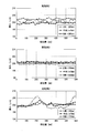
実施例2、実施例3、および比較例2の測定結果を表2および図10に示す。
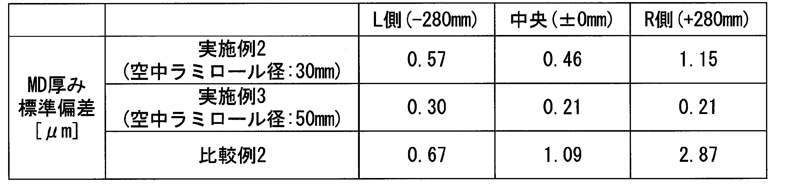
表2および図10から明らかなように、比較例2では移送方向MDの厚みが周期的に大きく変動している。幅方向TDの厚みの標準偏差の中央とL側、R側との差も大きい。一方、実施例2、3では移送方向MDの厚みの変動(標準偏差)が小さくなっている。特に、実施例2では幅方向TDの厚みの標準偏差の中央とL側、R側との差がさらに改善されているのがわかる。
1 積層フィルム
2 光硬化性樹脂層
3 第1基材フィルム
4 第2基材フィルム
5 耳部
10 硬化樹脂フィルムの製造装置
14 ラミネート部(密着手段)
14a ラミネートロール
48 ニップロール
48b 拡径部
2 光硬化性樹脂層
3 第1基材フィルム
4 第2基材フィルム
5 耳部
10 硬化樹脂フィルムの製造装置
14 ラミネート部(密着手段)
14a ラミネートロール
48 ニップロール
48b 拡径部
Claims (9)
- 液状の硬化性樹脂組成物からなるフィルム状の硬化性樹脂層を第1基材フィルムおよび第2基材フィルムの間に挟み込んでなる帯状の積層フィルムを長手方向に移送しながら、前記積層フィルムにエネルギー線を照射して前記硬化性樹脂層を硬化させて連続的に硬化樹脂フィルムを得る硬化樹脂フィルムの製造装置であって、
前記第1基材フィルムを供給する第1基材フィルム供給手段と、前記第2基材フィルムを供給する第2基材フィルム供給手段と、前記第1基材フィルムまたは前記第2基材フィルムに前記硬化性樹脂層を形成する樹脂層形成手段と、前記第1基材フィルムと前記第2基材フィルムとを前記硬化性樹脂層を挟んで密着させて積層フィルムを形成する密着手段と、を少なくとも備え、
前記密着手段は、前記第1基材フィルムまたは前記第2基材フィルムのうち、いずれか一方の表面だけに接するラミネートロールをからなることを特徴とする硬化樹脂フィルムの製造装置。 - 前記ラミネートロールの後段側には、前記積層フィルムを移送する駆動ロールが形成されており、前記ラミネートロールは、前記駆動ロールよりも直径が小さいことを特徴とする請求項1に記載の硬化樹脂フィルムの製造装置。
- 前記ラミネートロールの自重たわみ量が40μm以下である請求項1または2に記載の硬化樹脂フィルムの製造装置。
- 前記ラミネートロールの直径は、5mm以上、100mm以下の範囲であることを特徴とする請求項1から3のいずれか一項に記載の硬化樹脂フィルムの製造装置。
- 前記積層フィルムを介して前記駆動ロールに対向するニップロールが形成され、
前記ニップロールは、前記積層フィルムに対して所定の隙間を保って配されるロール本体と、該ロール本体の両側に形成され、前記積層フィルムの幅方向の周縁領域に接する拡径部とを有することを特徴とする請求項2から4のいずれか一項に記載の硬化樹脂フィルムの製造装置。 - 前記拡径部は、前記積層フィルムの幅方向のうち、前記硬化性樹脂層が形成された領域よりも外側に接することを特徴とする請求項5に記載の硬化樹脂フィルムの製造装置。
- 前記硬化性樹脂組成物は、透明な光硬化性樹脂組成物であることを特徴とする請求項1から6のいずれか一項に記載の硬化樹脂フィルムの製造装置。
- 前記透明な光硬化性樹脂組成物は、光重合性の炭素-炭素二重結合を複数個有する化合物であることを特徴とする請求項7に記載の硬化樹脂フィルムの製造装置。
- 請求項1から8のいずれか一項に記載の硬化樹脂フィルムの製造装置を用いた硬化樹脂フィルムの製造方法であって、
前記硬化性樹脂層を挟んで前記第1基材フィルムと前記第2基材フィルムとを密着させる密着工程を有し、
前記密着工程では、前記第1基材フィルムまたは前記第2基材フィルムのうち、いずれか一方の表面だけに前記ラミネートロールを接触させつつ前記積層フィルムを移送することを特徴とする硬化樹脂フィルムの製造方法。
Priority Applications (2)
| Application Number | Priority Date | Filing Date | Title |
|---|---|---|---|
| CN201980071127.3A CN113165257A (zh) | 2018-11-19 | 2019-11-18 | 固化树脂膜的制造装置及固化树脂膜的制造方法 |
| JP2020558374A JP7072670B2 (ja) | 2018-11-19 | 2019-11-18 | 硬化樹脂フィルムの製造装置及び硬化樹脂フィルムの製造方法 |
Applications Claiming Priority (2)
| Application Number | Priority Date | Filing Date | Title |
|---|---|---|---|
| JP2018216360 | 2018-11-19 | ||
| JP2018-216360 | 2018-11-19 |
Publications (1)
| Publication Number | Publication Date |
|---|---|
| WO2020105583A1 true WO2020105583A1 (ja) | 2020-05-28 |
Family
ID=70773685
Family Applications (1)
| Application Number | Title | Priority Date | Filing Date |
|---|---|---|---|
| PCT/JP2019/045061 Ceased WO2020105583A1 (ja) | 2018-11-19 | 2019-11-18 | 硬化樹脂フィルムの製造装置及び硬化樹脂フィルムの製造方法 |
Country Status (4)
| Country | Link |
|---|---|
| JP (1) | JP7072670B2 (ja) |
| CN (1) | CN113165257A (ja) |
| TW (1) | TWI750533B (ja) |
| WO (1) | WO2020105583A1 (ja) |
Citations (4)
| Publication number | Priority date | Publication date | Assignee | Title |
|---|---|---|---|---|
| JP2011116095A (ja) * | 2009-11-06 | 2011-06-16 | Mitsubishi Rayon Co Ltd | 樹脂積層体及び樹脂積層体の製造方法 |
| JP2013256089A (ja) * | 2012-06-14 | 2013-12-26 | Idemitsu Unitech Co Ltd | 表面保護部材およびその製造方法 |
| JP2014205304A (ja) * | 2013-04-12 | 2014-10-30 | 昭和電工株式会社 | 光硬化性樹脂フィルムの製造装置及び製造方法 |
| WO2017026346A1 (ja) * | 2015-08-11 | 2017-02-16 | 富士フイルム株式会社 | 積層フィルムの製造方法および積層フィルムの製造装置 |
Family Cites Families (4)
| Publication number | Priority date | Publication date | Assignee | Title |
|---|---|---|---|---|
| JP3964727B2 (ja) * | 2002-04-30 | 2007-08-22 | 日東電工株式会社 | 加工フィルムの製造方法及びその装置 |
| JP5837832B2 (ja) * | 2012-01-20 | 2015-12-24 | 富士フイルム株式会社 | 光硬化性樹脂層が形成された基板とその形成方法、静電容量型入力装置及び画像表示装置 |
| JP6270840B2 (ja) * | 2013-06-25 | 2018-01-31 | 昭和電工株式会社 | 光硬化性樹脂フィルムの製造方法 |
| WO2014208466A1 (ja) * | 2013-06-25 | 2014-12-31 | 昭和電工株式会社 | 光硬化性樹脂フィルムの製造装置および製造方法 |
-
2019
- 2019-11-15 TW TW108141623A patent/TWI750533B/zh active
- 2019-11-18 WO PCT/JP2019/045061 patent/WO2020105583A1/ja not_active Ceased
- 2019-11-18 JP JP2020558374A patent/JP7072670B2/ja active Active
- 2019-11-18 CN CN201980071127.3A patent/CN113165257A/zh active Pending
Patent Citations (4)
| Publication number | Priority date | Publication date | Assignee | Title |
|---|---|---|---|---|
| JP2011116095A (ja) * | 2009-11-06 | 2011-06-16 | Mitsubishi Rayon Co Ltd | 樹脂積層体及び樹脂積層体の製造方法 |
| JP2013256089A (ja) * | 2012-06-14 | 2013-12-26 | Idemitsu Unitech Co Ltd | 表面保護部材およびその製造方法 |
| JP2014205304A (ja) * | 2013-04-12 | 2014-10-30 | 昭和電工株式会社 | 光硬化性樹脂フィルムの製造装置及び製造方法 |
| WO2017026346A1 (ja) * | 2015-08-11 | 2017-02-16 | 富士フイルム株式会社 | 積層フィルムの製造方法および積層フィルムの製造装置 |
Also Published As
| Publication number | Publication date |
|---|---|
| TW202033344A (zh) | 2020-09-16 |
| JPWO2020105583A1 (ja) | 2021-09-02 |
| CN113165257A (zh) | 2021-07-23 |
| JP7072670B2 (ja) | 2022-05-20 |
| TWI750533B (zh) | 2021-12-21 |
Similar Documents
| Publication | Publication Date | Title |
|---|---|---|
| JP5889067B2 (ja) | 光学フィルムの製造方法 | |
| JP5995412B2 (ja) | 光学フィルムの製造方法、偏光板および画像表示装置の製造方法 | |
| JP2008194977A (ja) | 成形体の製造方法及び製造装置 | |
| JP2014205304A (ja) | 光硬化性樹脂フィルムの製造装置及び製造方法 | |
| JP6270840B2 (ja) | 光硬化性樹脂フィルムの製造方法 | |
| JP7072670B2 (ja) | 硬化樹脂フィルムの製造装置及び硬化樹脂フィルムの製造方法 | |
| US7850813B2 (en) | Method for producing a functional member having no base material | |
| JP6269650B2 (ja) | 光学フィルムロールの製造方法 | |
| JP2014226702A (ja) | 切断処理装置及び切断処理方法 | |
| JP2012226038A (ja) | 光学フィルムの製造方法、偏光板および画像表示装置 | |
| JP5912517B2 (ja) | 光学フィルムの製造方法、偏光板の製造方法および画像表示装置の製造方法 | |
| JP2000258615A (ja) | 拡散反射板の製造法及び転写フィルム | |
| JP2009292060A (ja) | レンズシート製造方法 | |
| JP2009080506A (ja) | 拡散反射板の製造法及び転写フィルム | |
| JP2013186455A (ja) | ハードコートフィルム製造方法 | |
| JP2004333697A (ja) | レンズシート | |
| JP3984417B2 (ja) | レンズシートの製造方法 | |
| JP2007140543A (ja) | レンズシートおよびその製造方法 | |
| JPH07205323A (ja) | 光学用シートの製造法 | |
| WO2014208466A1 (ja) | 光硬化性樹脂フィルムの製造装置および製造方法 | |
| KR20260063013A (ko) | 고경도 필름 제조 방법 및 장치 | |
| KR20120122919A (ko) | 광학 필름의 제조 방법, 편광판 및 화상 표시 장치 | |
| JP2000035502A (ja) | 両面レンチキュラーレンズシートの製造方法 | |
| JP2000035503A (ja) | 両面レンチキュラーレンズシートの製造方法 | |
| JP2002361653A (ja) | レンズシートの製造方法 |
Legal Events
| Date | Code | Title | Description |
|---|---|---|---|
| 121 | Ep: the epo has been informed by wipo that ep was designated in this application |
Ref document number: 19887692 Country of ref document: EP Kind code of ref document: A1 |
|
| ENP | Entry into the national phase |
Ref document number: 2020558374 Country of ref document: JP Kind code of ref document: A |
|
| NENP | Non-entry into the national phase |
Ref country code: DE |
|
| 122 | Ep: pct application non-entry in european phase |
Ref document number: 19887692 Country of ref document: EP Kind code of ref document: A1 |