WO2020105437A1 - 操作装置 - Google Patents
操作装置Info
- Publication number
- WO2020105437A1 WO2020105437A1 PCT/JP2019/043506 JP2019043506W WO2020105437A1 WO 2020105437 A1 WO2020105437 A1 WO 2020105437A1 JP 2019043506 W JP2019043506 W JP 2019043506W WO 2020105437 A1 WO2020105437 A1 WO 2020105437A1
- Authority
- WO
- WIPO (PCT)
- Prior art keywords
- cam
- operating
- axial direction
- holding
- operating device
- Prior art date
- Legal status (The legal status is an assumption and is not a legal conclusion. Google has not performed a legal analysis and makes no representation as to the accuracy of the status listed.)
- Ceased
Links
Images






Classifications
-
- A—HUMAN NECESSITIES
- A63—SPORTS; GAMES; AMUSEMENTS
- A63F—CARD, BOARD, OR ROULETTE GAMES; INDOOR GAMES USING SMALL MOVING PLAYING BODIES; VIDEO GAMES; GAMES NOT OTHERWISE PROVIDED FOR
- A63F13/00—Video games, i.e. games using an electronically generated display having two or more dimensions
- A63F13/20—Input arrangements for video game devices
- A63F13/24—Constructional details thereof, e.g. game controllers with detachable joystick handles
-
- G—PHYSICS
- G06—COMPUTING OR CALCULATING; COUNTING
- G06F—ELECTRIC DIGITAL DATA PROCESSING
- G06F3/00—Input arrangements for transferring data to be processed into a form capable of being handled by the computer; Output arrangements for transferring data from processing unit to output unit, e.g. interface arrangements
- G06F3/01—Input arrangements or combined input and output arrangements for interaction between user and computer
- G06F3/03—Arrangements for converting the position or the displacement of a member into a coded form
- G06F3/033—Pointing devices displaced or positioned by the user, e.g. mice, trackballs, pens or joysticks; Accessories therefor
- G06F3/0338—Pointing devices displaced or positioned by the user, e.g. mice, trackballs, pens or joysticks; Accessories therefor with detection of limited linear or angular displacement of an operating part of the device from a neutral position, e.g. isotonic or isometric joysticks
-
- H—ELECTRICITY
- H01—ELECTRIC ELEMENTS
- H01H—ELECTRIC SWITCHES; RELAYS; SELECTORS; EMERGENCY PROTECTIVE DEVICES
- H01H25/00—Switches with compound movement of handle or other operating part
- H01H25/04—Operating part movable angularly in more than one plane, e.g. joystick
-
- H—ELECTRICITY
- H01—ELECTRIC ELEMENTS
- H01H—ELECTRIC SWITCHES; RELAYS; SELECTORS; EMERGENCY PROTECTIVE DEVICES
- H01H25/00—Switches with compound movement of handle or other operating part
- H01H25/06—Operating part movable both angularly and rectilinearly, the rectilinear movement being along the axis of angular movement
Definitions
- the present invention relates to an operating device.
- operation devices that can tilt operation members such as joysticks in multiple directions have been used.
- This type of operating device is provided with a returning mechanism that urges the tilted operating member toward the initial position and automatically returns the operating member to the initial position.
- the user tilts the operating member against the force (axial operating torque, hereinafter referred to as "operating force") applied to the operating member by the return mechanism.
- operating force axial operating torque
- the greater the operating force the greater the force required to tilt the operating member at a predetermined angle.
- the operating force of the operating device is preferably small when operating the operating member quickly, and is preferably large when operating the operating member finely. Further, the operating force of the operating device is preferably small when the user is tired. As described above, the preferable operating force changes depending on the situation in which the operating device is used and the state of the user. However, in the conventional operating device, the operating force is predetermined by the design, and thus the user cannot adjust the operating force.
- the present invention has been made in view of the above problems, and an object of the present invention is to provide an operating device that allows a user to adjust the operating force.
- An operating device includes a housing, a cylindrical operating member that has a step portion on an inner peripheral surface thereof, and is tiltable, and is rotatable in a first direction in response to a tilting operation of the operating member.
- a return mechanism wherein the return mechanism includes a shaft portion extending in the axial direction of the operating member, and an actuator having a bottom portion formed at one end of the shaft portion and abutting a bottom surface of the housing, One end of the shaft portion is inserted, is movable in the axial direction, is fixed in the circumferential direction of the operating member, and has a slide member having a first cam surface at one end, and a central portion of the shaft portion is inserted, It is movable in the axial direction, is fixed in the circumferential direction by the step portion, has at one end a second cam surface facing the first cam surface, and has a first cam surface and a second cam surface.
- a cam member that is urged in one of the circumferential directions by contact, a first elastic member that is arranged between the slide member and the cam member, and a cam member that is arranged between the cam member and the bottom portion.
- a second elastic member that is urged in one of the circumferential directions by contact, a first elastic member that is
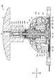
- FIG. 2 is a sectional view of the operating device of FIG. 1 taken along the line AA.
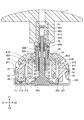
- FIG. 2 is a sectional view of the operating device of FIG. 1 taken along line BB.
- FIG. 2 is a sectional view of the operating member of FIG. 1 taken along the line BB.
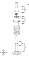
- FIG. 2 is an external perspective view of the return mechanism of FIG. 1.
- the disassembled perspective view of the return mechanism of FIG. Sectional drawing which shows the state of the operating device before and behind the tilting operation of an operating member.
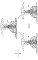
- FIG. 6 is a partially enlarged view showing the operation of the return mechanism when the push button is pressed. Sectional drawing which shows the state change of the operating device by the pressing operation of a push button.
- the operation device 100 will be described with reference to FIGS. 1 to 10.
- the operating device 100 according to the present embodiment includes an operation member that can be tilted and a return mechanism that automatically returns the tilted operation member to the initial position.
- the operating device 100 can be used, for example, as a controller for a home-use game machine or a wireless control device, but the use of the operating device 100 is not limited to this.
- FIG. 1 is an external perspective view showing an example of an operating device 100 according to the present embodiment.
- FIG. 2 is an exploded perspective view of the operating device 100 of FIG. 3 is a cross-sectional view of the operating device 100 of FIG. 1 taken along the line AA.
- FIG. 4 is a cross-sectional view of the operating device 100 of FIG. 1 taken along the line BB.
- FIG. 5 is a sectional view of the operating member 5 of FIG. 1 taken along the line BB.
- FIG. 6 is an external perspective view of the return mechanism 6 of FIG.
- FIG. 7 is an exploded perspective view of the return mechanism 6 of FIG.
- the operation device 100 will be described with reference to the directions shown in the drawings (X1, X2, Y1, Y2, Z1, Z2 directions).
- the X1 and X2 directions are collectively referred to as the X direction
- the Y1 and Y2 directions are collectively referred to as the Y direction
- the Z1 and Z2 directions are collectively referred to as the Z direction.
- the Z1 direction and the Z2 direction may be referred to as an upward direction and a downward direction, respectively.
- the X, Y and Z directions are orthogonal to each other.
- the operating device 100 includes an operating knob 1, a housing 2, a first holding member 3, a second holding member 4, an operating member 5, a return mechanism 6, and a detection mechanism.
- the mechanism 7 and the substrate 8 are provided.
- the operation knob 1 is a member that directly receives an operation from the user.
- the operation knob 1 is made of, for example, resin or rubber.
- the operation knob 1 has an operation unit 11 and a connection unit 12.
- the operation unit 11 is a part that directly receives an operation from a user.
- the operation unit 11 has a circular shape in the XY plane, a convex upper surface, and a flat lower surface, but the shape of the operation unit 11 is not limited to this.
- the operation unit 11 can have an arbitrary shape that a user can easily operate with his / her finger.
- the operation unit 11 has a through hole 13 penetrating from the upper surface to the lower surface. Although omitted in the illustrated example, a push button is inserted into the through hole 13 such that the upper end thereof projects from the upper surface of the operation unit 11. The user presses a push button to press a slide member 62, which will be described later, to adjust the operating force of the return mechanism 6.
- connection part 12 is a part for connecting the operation knob 1 to the operation member 5.
- the connection portion 12 is formed in a tubular shape extending in the vertical direction from the lower surface of the operation portion 11. By inserting the upper end of the operating member 5 inside the connecting portion 12, the operating knob 1 and the operating member 5 are connected.
- the connecting portion 12 is formed such that the lower opening of the through hole 13 and the upper opening of the operating member 5 face each other.
- the connecting portion 12 is formed so as to include the lower opening of the through hole 13 inside. Thereby, the through hole 13 and the inside of the operation member 5 are connected to each other, and the above-described push button can be arranged so that the lower end is in contact with the upper end of the slide member 62.
- the configuration of the operation knob 1 is not limited to the example shown in the figure.
- the operation knob 1 can have any configuration that can accept an operation from a user.
- the operation knob 1 may be formed integrally with the operation member 5, or may be fixed by a method such as screwing or adhesion.
- the housing 2 is a member that houses each component of the operation equipment 100.
- the housing 2 includes a case 21 and a frame 22.
- the case 21 is a member that constitutes the upper part of the housing 2.
- the case 21 is made of resin, for example.
- the case 21 has a hollow dome shape, and the lower surface is fixed to the upper surface of the frame 22. As shown in FIGS. 3 and 4, the case 21 has bearing portions 211 to 214.
- the bearing portion 211 is a portion that holds a shaft portion 32 of the first holding member 3 which will be described later. As shown in FIG. 4, the bearing portion 211 is formed on the inner peripheral surface of the case 21 on the X1 side. In the illustrated example, the bearing 211 is a through hole, but it may be a recess that does not penetrate.
- the bearing portion 212 is a portion that holds a shaft portion 34 of the first holding member 3 which will be described later. As shown in FIG. 4, the bearing portion 212 is formed on the inner peripheral surface of the case 21 on the X2 side. In the illustrated example, the bearing 212 is a through hole, but it may be a recess that does not penetrate.
- the bearing portion 213 is a portion that holds a shaft portion 42 of the second holding member 4 which will be described later. As shown in FIG. 3, the bearing portion 213 is formed on the Y1 side inner peripheral surface of the case 21. In the illustrated example, the bearing portion 213 is a through hole, but it may be a recess that does not penetrate.
- the bearing portion 214 is a portion that accommodates a shaft portion 44 of the second holding member 4, which will be described later. As shown in FIG. 3, the bearing portion 214 is formed on the Y2 side inner peripheral surface of the case 21.
- the bearing portion 214 unlike the bearing portions 211 to 213, does not have a portion that supports the shaft portion 44 from below.
- the frame 22 is a member that forms the bottom surface of the housing 2.
- the frame 22 is made of metal, for example.
- the frame 22 has a bottom surface portion 221 and a support portion 222, as shown in FIG. 4.
- the bottom surface portion 221 is a portion that constitutes the bottom surface of the housing 2.
- the bottom surface portion 221 has a substantially rectangular flat plate shape, and the case 21 is fixed to the top surface thereof.
- the support part 222 is a part that supports the side surface of the case 21.
- the support part 222 is formed to extend upward from the X1 side and the X2 side of the bottom surface part 221.
- the support portion 222 and the side surface of the case 21 are in contact with each other, so that the displacement of the case 21 in the X direction is suppressed.
- the support part 222 may be provided on at least one of the Y1 side and the Y2 side of the bottom surface part 221.
- a guide portion 223 is provided on the upper surface of the bottom surface portion 221 of the frame 22.
- the guide portion 223 is a portion that guides the sliding of the actuator 61 described later.
- the guide portion 223 is made of resin, for example.
- the guide portion 223 is annular and is fixed to the upper surface of the bottom surface portion 221 so as to surround the bottom portion 612 of the actuator 61.
- the guide portion 223 is formed such that the diameter of the inner circumference becomes wider toward the upper side.
- the configuration of the housing 2 is not limited to the example shown in the figure.
- the housing 2 may have any configuration capable of accommodating each configuration of the operation equipment 100.
- the first holding member 3 is a member that holds the operation member 5 so as to be tiltable in the Y direction (first direction).
- the first holding member 3 is made of resin, for example.
- the first holding member 3 is held by the case 21 so as to be rotatable about the X direction as a rotation axis.
- the rotation corresponds to the rotation whose rotation angle is limited to a predetermined range.
- the first holding member 3 has a holding portion 31, shaft portions 32 and 34, stopper portions 33 and 35, and a driving portion 36.
- the sandwiching portion 31 is a portion that sandwiches the operation member 5.
- the holding portion 31 is formed in a spherical shape with an opening in the center, covering the upper surface of a base portion 52 of the operation member 5 described later, and the shaft portion 51 of the operation member 5 described later is inserted into the opening portion.
- the sandwiching portion 31 is formed so as to abut on the Y1 side and the Y2 side of the operation member 5 and separate from the X1 side and the X2 side of the operation member 5.
- the shaft portion 32 is a rotation shaft of the first holding member 3 extending in the X1 direction from the X1 side of the holding portion 31.
- the shaft portion 32 is arranged so as to face the shaft portion 34.
- the shaft portion 32 is rotatably held by the bearing portion 211 of the case 21 (see FIG. 4).
- the stopper portion 33 is a portion that restricts the movement of the first holding member 3 in the X1 direction.
- the stopper portion 33 is formed so as to extend in the X1 direction from the X1 side of the sandwiching portion 31, and the end portion on the X1 side contacts the inner peripheral surface of the case 21 on the X1 side. When the stopper portion 33 and the inner peripheral surface of the case 21 come into contact with each other, the movement of the first holding member 3 in the X1 direction is restricted.
- the shaft portion 34 is a rotation shaft of the first holding member 3 extending in the X2 direction from the X2 side of the sandwiching portion 31.
- the shaft portion 34 is arranged so as to face the shaft portion 32.
- the shaft portion 34 is rotatably held by the bearing portion 212 of the case 21 (see FIG. 4).
- the stopper portion 35 is a portion that restricts the movement of the first holding member 3 in the X2 direction.
- the stopper portion 35 is formed so as to extend in the X2 direction from the X2 side of the sandwiching portion 31, and the end portion on the X2 side contacts the inner peripheral surface of the case 21 on the X2 side. When the stopper portion 35 and the inner peripheral surface of the case 21 come into contact with each other, the movement of the first holding member 3 in the X2 direction is restricted.
- the drive unit 36 is a portion that drives a first detection member 71 described later.
- the drive unit 36 extends downward from the X1 side of the sandwiching unit 31 and sandwiches a later-described convex portion 712 of the first detection member 71 from the Y1 side and the Y2 side.
- the first holding member 3 is rotatably held by the case 21 with the X direction as the rotation axis. Further, the first holding member 3 holds the operating member 5 from the Y1 side and the Y2 side. Therefore, when the operating member 5 tilts in the Y direction, the first holding member 3 rotates in the Y direction together with the operating member 5. That is, the first holding member 3 holds the operating member 5 so as to be tiltable in the Y direction. When the operating member 5 is tilted in the X direction, the operating member 5 moves inside the opening of the holding portion 31. Therefore, the first holding member 3 does not prevent the operation member 5 from tilting in the X direction.
- the configuration of the first holding member 3 is not limited to the example shown in the figure.
- the first holding member 3 can have any configuration capable of holding the operation member 5 so as to be tiltable in the Y direction.
- the operation device 100 may be configured without the first holding member 3. In this case, the operation member 5 can be tilted only in the X direction.
- the second holding member 4 is a member that holds the operation member 5 so as to be tiltable in the X direction (second direction).
- the second holding member 4 is made of resin, for example.
- the second holding member 4 is held by the case 21 so as to be rotatable about the Y direction as a rotation axis. As shown in FIG. 2, the second holding member 4 has sandwiching portions 41A and 41B, shaft portions 42 and 44, and a driving portion 43.
- the sandwiching portion 41A is a portion that sandwiches the operation member 5.
- the sandwiching portion 41A is formed in a spherical shape with an opening in the center, which covers the side surface of the base portion 52 of the operation member 5 on the X1 side described later, and the convex portion 55 of the operation member 5 described later is inserted into the opening portion (FIG. 4). reference).
- the sandwiching portion 41B is a portion that sandwiches the operation member 5.
- the sandwiching portion 41B is formed in a spherical shape with an opening in the center, which covers the side surface of the operation member 5 on the X2 side of the base portion 52 described later, and the convex portion 56 of the operation member 5 described later is inserted into the opening portion (FIG. 4). reference).
- the sandwiching portions 41A and 41B are integrally formed, and the Y1 side and the Y2 side are connected.
- the spherical portion formed by the sandwiching portions 41A and 41B is referred to as the sandwiching portion 41.
- the sandwiching portion 41 is formed so as to contact the X1 side and the X2 side of the operation member 5 and separate from the Y1 side and the Y2 side of the operation member 5.
- the shaft portion 42 is a rotation shaft of the second holding member 4 extending in the Y1 direction from the Y1 side of the holding portion 41.
- the shaft portion 42 is arranged so as to face the shaft portion 44.
- the shaft portion 42 is rotatably held by the bearing portion 213 of the case 21 (see FIG. 3).
- the drive unit 43 is a portion that drives a second detection member 72 described later.
- the drive unit 43 extends downward from the Y1 side of the sandwiching unit 41 and sandwiches a later-described convex portion 722 of the second detection member 72 from the X1 side and the X2 side.
- the shaft portion 44 is a rotation shaft of the second holding member 4 extending in the Y2 direction from the Y2 side of the holding portion 41.
- the shaft portion 44 is arranged so as to face the shaft portion 42.
- the shaft portion 44 is rotatably housed by the bearing portion 214 of the case 21, and is supported from below by a third detection member 73 described below (see FIG. 3). As a result, the shaft portion 44 is rotatably held.
- the Y2 side end of the shaft portion 44 and the inner peripheral surface of the bearing portion 214 contact with each other, so that the movement of the second holding member 4 in the Y2 direction is restricted.
- the second holding member 4 is rotatably held by the case 21 with the Y direction as the rotation axis. Further, the second holding member 4 holds the operating member 5 from the X1 side and the X2 side. Therefore, when the operation member 5 tilts in the X direction, the second holding member 4 rotates in the X direction together with the operation member 5. That is, the second holding member 4 holds the operating member 5 so as to be tiltable in the X direction.
- the operating member 5 moves inside the opening (between the Y1 side and the Y2 side) of the holding section 41. Therefore, the second holding member 4 does not prevent the operation member 5 from tilting in the Y direction.
- the configuration of the second holding member 4 is not limited to the example shown in the figure.
- the second holding member 4 can have any configuration capable of holding the operation member 5 so as to be tiltable in the X direction.
- the operation device 100 may be configured without the second holding member 4. In this case, the operation member 5 can be tilted only in the Y direction.
- the operation member 5 is a member that receives an operation from a user via the operation knob 1.
- the operation member 5 is held by the first holding member 3 so as to be tiltable in the Y direction, and is held by the second holding member 4 so as to be tiltable in the X direction.
- the operation member 5 is connected to a lower portion of the operation knob 1 and tilts in the X direction and the Y direction according to a user operation on the operation knob 1.
- the operation member 5 is formed in a hollow cylindrical shape and houses the return mechanism 6 inside.
- the operation member 5 is held by the first holding member 3 and the second holding member 4 so that the axial direction is the Z direction in the initial position.
- the initial position of the operating member 5 is the position when the operating member 5 is not operated.
- the operation member 5 includes a shaft portion 51, a base portion 52, convex portions 55 and 56, and a step portion 57.
- the shaft portion 51 is a tubular portion extending in the axial direction.
- the shaft portion 51 is formed so as to extend from the base portion 52 in the Z1 direction, is inserted into the openings of the first holding member 3 and the second holding member 4, and is exposed upward from the housing 2.
- the upper end of the shaft portion 51 is inserted into the connecting portion 12 of the operation knob 1. As a result, the operation knob 1 and the operation member 5 are connected.
- a recess 53 extending in the axial direction is formed on the inner peripheral surface of the shaft 51.
- the recess 53 fixes the slide member 62 to the operating member 5 in the circumferential direction by fitting with the projection 622 of the slide member 62 described later.
- the recess 53 prevents the slide member 62 from rotating with respect to the operation member 5 by fitting with the projection 622.
- the operating member 5 has two recesses 53, but may have one or three or more recesses 53.
- a retaining portion 54 that is a downward surface perpendicular to the axial direction is formed.
- the retaining portion 54 prevents the slide member 62 from coming off the operation member 5 by coming into contact with the lower end of the slide member 62 described later.
- the base portion 52 is a substantially spherical portion formed on the lower end of the shaft portion 51.
- the base portion 52 is housed inside the housing 2 and is held by the holding portion 31 of the first holding member 3 and the holding portion 41 of the second holding member 4.
- the convex portion 55 is a portion protruding from the X1 side of the base portion 52 in the X1 direction.
- the convex portion 55 is inserted into the opening of the holding portion 41A.
- the convex portion 55 is formed inside the opening of the holding portion 41A so as to be rotatable in the Y direction.
- the convex portion 56 is a portion protruding from the X2 side of the base 52 in the X2 direction.
- the convex portion 56 is inserted into the opening of the holding portion 41B.
- the convex portion 56 is formed inside the opening of the holding portion 41B so as to be rotatable in the Y direction.
- the step portion 57 is a portion having an axial step shape formed on the inner peripheral surface of the base portion 52 in order to adjust the axial height (Z direction position) of the cam member 63 described later.
- the step portion 57 has three step portions 58A to 58D, respectively.
- the steps 58A to 58D are not distinguished, they are referred to as the steps 58.
- the step portion 58 is a portion protruding inward from the inner peripheral surface of the base portion 52 and has a lower surface.
- the step portions 58 are arranged at equal intervals (every 30 °) in the circumferential direction of the operation member 5 along the inner peripheral surface of the base portion 52.
- the lower surface of the step portion 58 is inclined in the axial direction (Z direction) with respect to the circumferential direction (XY plane) of the operation member 5 and extends along the rotation direction R of the cam member 63 (direction of arrow R in FIG. 5).
- the operation member 5 is formed so that its axial height from the lower end is high.
- the axial height H from the lower end of the operating member 5 to the center of the lower surface of the step portion 58 will be referred to as the axial height H of the step portion 58.
- the steps 58A to 58D have the same width in the circumferential direction, the axial height HA of the step 58A is first highest, the axial height HB of the step 58B is second highest, and the step 58C is high. Is formed such that the axial height HC of the step 58D is the third highest and the axial height HD of the step portion 58D is the fourth highest (the lowest).
- the steps 58A to 58D are arranged in this order along the rotation direction R.
- the three step portions 58A are arranged at equal intervals (every 120 °) in the circumferential direction of the operation member 5, and the three step portions 58B are arranged at equal intervals (every 120 °) in the circumferential direction of the operation member 5.
- the three step portions 58C are arranged at equal intervals (every 120 °) in the circumferential direction of the operation member 5, and the three step portions 58D are arranged at equal intervals (every 120 °) in the circumferential direction of the operation member 5.
- the step portion 57 having three step shapes of four steps in the circumferential direction is formed.
- the height of the cam member 63 in the axial direction is adjusted in three steps by the step portion 57.
- the configuration of the step portion 57 is not limited to the example shown in the figure.
- the step portion 57 can have any configuration capable of adjusting the axial height of the cam member 63.
- the step portion 57 may be configured to have a step shape of (N + 1) steps. Further, the step shape of the step portion 57 is not limited to three.
- the configuration of the operation member 5 is not limited to the example shown in the figure.
- the operation member 5 can have an arbitrary configuration capable of receiving an operation from a user via the operation knob 1 and accommodating the return mechanism 6 inside.
- the return mechanism 6 will be described later.
- the detection mechanism 7 is a mechanism that detects the operation of the operation member 5 (operation knob 1) by the user.
- the detection mechanism 7 includes a first detection member 71, a second detection member 72, and a third detection member 73.
- the first detection member 71 is a member for detecting a tilting operation of the operation member 5 in the Y direction.
- the first detection member 71 has a holding portion 711, a convex portion 712, and a movable contact 713.
- the holding portion 711 is a portion that holds the movable contact 713.
- the holding portion 711 is made of, for example, resin.
- the holding portion 711 is formed so as to extend in the Y direction, and the movable contact 713 is fixed to the lower surface thereof.
- the holder 711 is arranged on the substrate 8.
- the convex portion 712 is a portion protruding in the X2 direction from the side surface of the holding portion 711 on the X2 side.
- the convex portion 712 is formed of resin, for example.
- the protrusion 712 is sandwiched by the drive unit 36 from the Y1 side and the Y2 side.
- the holding part 711 is arranged so that the drive part 36 can sandwich the convex part 712.
- the movable contact 713 is a contact fixed to the lower surface of the holding portion 711.
- the movable contact 713 is made of metal, for example.
- the movable contact 713 is formed so that a part thereof can contact the upper surface of the substrate 8.
- the first holding member 3 rotates in the Y direction as the operating member 5 tilts, and the drive unit 36 rotates in the Y direction.
- the drive unit 36 rotates in the Y direction
- the convex portion 712 held by the drive unit 36 is driven in the Y direction
- the holding unit 711 is driven in the Y direction.
- the holding portion 711 is driven in the Y direction
- the movable contact 713 held by the holding portion 711 slides on the substrate 8 in the Y direction. That is, the movable contact 713 slides in the Y direction as the operating member 5 tilts in the Y direction. Therefore, by detecting the position of the movable contact 713 by the circuit provided on the upper surface of the substrate 8, the tilt of the operating member 5 in the Y direction can be detected.
- the second detection member 72 is a member for detecting a tilting operation of the operation member 5 in the X direction.
- the second detection member 72 has a holding portion 721, a convex portion 722, and a movable contact 723.
- the holding portion 721 is a portion that holds the movable contact 723.
- the holding portion 721 is made of, for example, resin.
- the holding portion 721 is formed so as to extend in the X direction, and the movable contact 723 is fixed to the lower surface of the holding portion 721.
- the holder 721 is arranged on the substrate 8.
- the convex portion 722 is a portion protruding in the Y2 direction from the side surface of the holding portion 721 on the Y2 side.
- the convex portion 722 is formed of resin, for example.
- the convex portion 722 is sandwiched by the drive unit 43 from the X1 side and the X2 side.
- the holding portion 721 is arranged so that the driving portion 43 can sandwich the convex portion 722.
- the movable contact 723 is a contact fixed to the lower surface of the holding portion 721.
- the movable contact 723 is formed of, for example, metal.
- the movable contact 723 is formed so that a part thereof can contact the upper surface of the substrate 8.
- the second holding member 4 rotates in the X direction as the operating member 5 tilts, and the drive unit 43 rotates in the X direction.
- the drive unit 43 rotates in the X direction
- the convex portion 722 held by the drive unit 43 is driven in the X direction
- the holding unit 721 is driven in the X direction.
- the holding portion 721 is driven in the X direction
- the movable contact 723 held by the holding portion 721 slides on the substrate 8 in the X direction. That is, the movable contact 723 slides in the X direction as the operation member 5 tilts in the X direction. Therefore, the tilt of the operating member 5 in the X direction can be detected by detecting the position of the movable contact 723 by the circuit provided on the upper surface of the substrate 8.
- the third detection member 73 is a member for detecting a pressing operation of the operation member 5 in the Z direction (axial direction).
- the third detection member 73 is made of resin, for example.
- the third detection member 73 has a support portion 731 and a pressing portion 732.
- the support portion 731 is a portion that supports the shaft portion 44 from below.
- the support portion 731 is arranged below the shaft portion 44.
- the shaft portion 44 rotates on the support portion 731.
- the pressing portion 732 is a portion that presses the movable contact 83 described later.
- the pressing portion 732 is arranged on the movable contact 83.
- the configuration of the detection mechanism 7 is not limited to the example shown in the figure.
- the detection mechanism 7 may have any configuration capable of detecting the tilting operation and the pressing operation of the operation member 5.
- the operation device 100 may have a configuration that does not include one or two of the first detection member 71, the second detection member 72, and the third detection member 73.
- the operation device 100 can detect only the tilting operation and the pressing operation of the operation member 5 in the X direction.
- the second detection member 72 is not provided
- the operation device 100 can detect only the tilting operation and the pressing operation of the operation member 5 in the Y direction.
- the third detection member 73 is not provided, the operation device 100 can detect only the tilting operation of the operation member 5 in the X direction and the Y direction.
- the board 8 is a printed board provided with a circuit for detecting the operation of the operation member 5 by the user.
- the substrate 8 is, for example, a flexible substrate.
- the substrate 8 is arranged on the bottom surface of the housing 2 (bottom surface portion 221 of the frame 22), and the terminals are exposed to the outside of the housing 2.
- a circuit for detecting the operation of the operation member 5 by the user is mounted on the upper surface of the board 8.
- the fixed contact 81 for detecting the position of the movable contact 713 in the Y direction is mounted on the sliding path of the movable contact 713 on the substrate 8.
- a fixed contact 82 for detecting the position of the movable contact 723 in the X direction is mounted on the sliding path of the movable contact 723 on the board 8.
- a movable contact 83 for detecting the pressing operation of the operating member 5 and a fixed contact for detecting the pressing of the movable contact 83 are mounted on a portion of the substrate 8 corresponding to the pressing portion 732.
- the movable contact 83 is, for example, a metal contact, but is not limited to this.
- the configuration of the substrate 8 is not limited to the example shown in the figure.
- the substrate 8 may have any configuration capable of detecting the operation of the operation member 5 by the user.
- the substrate 8 may be a rigid substrate.
- the return mechanism 6 is a mechanism that urges the tilted operation member 5 toward the initial position and automatically returns the operation member 5 to the initial position.
- the return mechanism 6 tilts as the operating member 5 tilts, and applies an operating force toward the initial position to the operating member 5.
- the return mechanism 6 includes a knock mechanism for adjusting the operating force in multiple stages.
- the return mechanism 6 is arranged inside the tubular operation member 5. As shown in FIGS. 6 and 7, the return mechanism 6 includes an actuator 61, a slide member 62, a cam member 63, a first elastic member 64, and a second elastic member 65.
- the actuator 61 is a member that serves as a shaft that supports other components of the return mechanism 6.
- the actuator 61 is made of resin, for example.
- the actuator 61 has a shaft portion 611 and a bottom portion 612.
- the shaft portion 611 is a portion extending from the upper surface of the bottom portion 612 in the axial direction (Z1 direction) of the operation member 5.
- the shaft portion 611 is inserted into the slide member 62, the cam member 63, the first elastic member 64, and the second elastic member 65, and functions as these shafts.
- the shaft portion 611 is formed such that the upper portion 613 is thinner than the lower portion 614.
- the bottom portion 612 is a disc-shaped portion that comes into contact with the bottom surface of the housing 2 (the top surface of the frame 22).
- the bottom portion 612 is formed at the lower end (one end) of the shaft portion 611.
- the actuator 61 is arranged such that the bottom portion 612 is located at the center of the guide portion 223 when not in operation. When the actuator 61 tilts as the operating member 5 tilts, the bottom portion 612 slides on the bottom surface of the housing 2 and the inner peripheral surface of the guide portion 223 as the actuator 61 tilts.
- the configuration of the actuator 61 is not limited to the example shown in the figure.
- the actuator 61 may have any structure that can support the other structure of the return mechanism 6 as an axis.
- the slide member 62 is a member that rotates the cam member 63 in response to a pressing operation of a push button provided on the operation knob 1.
- the slide member 62 is made of resin, for example.
- the slide member 62 is formed in a tubular shape extending in the axial direction with the upper end closed, and the upper end of the shaft portion 611 of the actuator 61 is inserted therein. As a result, the slide member 62 is supported so as to be movable in the axial direction with respect to the operation member 5 and the actuator 61.
- the slide member 62 has a tubular portion 621, a convex portion 622, a support portion 623, and a first cam surface 624.
- the tubular portion 621 is a tubular portion that is closed at the upper end and extends in the axial direction.
- the inner diameter of the tubular portion 621 is formed slightly larger than the outer diameter of the upper portion 613 of the shaft portion 611 of the actuator 61, and the outer diameter of the tubular portion 621 is formed slightly smaller than the inner diameter of the shaft portion 51 of the operation member 5. ..
- the cylindrical portion 621 is inserted into the shaft portion 611 of the actuator 61 and the shaft portion 51 of the operation member 5 (see FIG. 4).
- the lower end of the tubular portion 621 is formed so that the outer diameter is larger than the outer diameters of other portions.
- the convex portion 622 is a portion that is formed so as to extend in the axial direction and that protrudes from the outer peripheral surface of the tubular portion 621.
- the convex portion 622 fits into the concave portion 53 formed on the inner peripheral surface of the shaft portion 51, and fixes the slide member 62 to the operating member 5 in the circumferential direction. To do.
- the convex part 622 prevents the slide member 62 from rotating with respect to the operation member 5 by fitting with the concave part 53. Therefore, the convex portion 622 is arranged at a position corresponding to the concave portion 53.
- the slide member 62 has two convex portions 622, but may have one or three or more.
- the support portion 623 is a downward surface that is formed inside the tubular portion 621 and that is perpendicular to the axial direction.
- the support portion 623 is formed by increasing the inner diameter of the lower portion of the tubular portion 621.
- the support portion 623 supports the upper end of the first elastic member 64.
- the first cam surface 624 is a cam surface formed on the lower surface of the lower end of the tubular portion 621.
- the first cam surface 624 is formed by a plurality of convex portions arranged on the outer peripheral portion of the lower surface of the lower end of the tubular portion 621. Each convex portion has the same shape and is formed in a substantially triangular shape projecting downward from the lower surface of the lower end of the tubular portion 621.
- the first cam surface 624 faces a second cam surface 634 of the cam member 63, which will be described later.
- the configuration of the slide member 62 is not limited to the example shown in the figure.
- the slide member 62 may have any configuration capable of rotating the cam member 63 in response to a pressing operation of a push button provided on the operation knob 1.
- the cam member 63 is a member that adjusts the operating force applied to the operation member 5.
- the cam member 63 is made of resin, for example.
- the cam member 63 is formed in a tubular shape extending in the axial direction, and the central portion of the shaft portion 611 of the actuator 61 is inserted therein. Accordingly, the cam member 63 is supported so as to be movable in the axial direction with respect to the operation member 5 and the actuator 61.
- the cam member 63 rotates in the rotation direction R (direction of arrow R in FIG. 6) every time the cam member 63 is pressed by the slide member 62.
- the cam member 63 has a tubular portion 631, a support portion 632, three convex portions 633, and a second cam surface 634.
- the tubular portion 631 is a tubular portion extending in the axial direction.
- the inner diameter of the tubular portion 631 is formed slightly larger than the outer diameter of the lower portion 614 of the shaft portion 611 of the actuator 61. Further, the outer diameter of the tubular portion 631 is formed to be substantially equal to the outer diameter of the lower end of the slide member 62 and smaller than the inner diameter of the second elastic member 65.
- the tubular portion 631 is inserted into the shaft portion 611 of the actuator 61 and the shaft portion 51 of the operation member 5 and the second elastic member 65 (see FIG. 4).
- the upper end of the cylindrical portion 631 is formed so that the inner diameter is smaller than the inner diameters of other portions and slightly larger than the outer diameter of the upper portion 613 of the shaft portion 611 of the actuator 61.
- the lower end of the first elastic member 64 is supported by the upper end of the tubular portion 631. Further, since the upper end of the tubular portion 631 and the lower portion 614 of the shaft portion 611 of the actuator 61 contact each other, the downward movement of the cam member 63 with respect to the actuator 61 is restricted.
- the support portion 632 is a downward surface that is formed on the outer peripheral surface of the tubular portion 631 and that is perpendicular to the axial direction.
- the support portion 632 is formed by increasing the outer diameter of a part of the tubular portion 631.
- the support portion 632 supports the upper end of the second elastic member 65.
- the convex portion 633 is a portion protruding outward from the outer peripheral surface of the tubular portion 631.
- the convex portion 633 is provided in the central portion where the outer diameter of the cylindrical portion 631 is large, but it can be provided at an arbitrary position above the support portion 632.
- the three convex portions 633 have the same shape and are arranged on the outer peripheral surface of the tubular portion 631 at the same height in the axial direction and at equal intervals in the circumferential direction.
- the convex portion 633 is formed to have the same width in the circumferential direction as the step portion 58. Further, the convex portion 633 has an upper surface. The upper surface of the convex portion 633 is inclined in the axial direction (Z direction) with respect to the circumferential direction (XY plane), and the height in the axial direction from the lower end of the actuator 61 increases along the rotation direction R. Formed in. More specifically, the upper surface of the convex portion 633 is formed so as to be parallel to the lower surface of the step portion 58.
- the axial height h from the lower end of the actuator 61 (bottom portion 612) to the center of the upper surface of the convex portion 633 is referred to as the axial height h of the cam member 63.
- the cam member 63 when not operated, the cam member 63 is arranged in the circumferential direction in a state where the three convex portions 633 are in contact with the three step portions 58A, the three step portions 58B, or the three step portions 58C, respectively. Fixed.
- the height h of the cam member 63 in the axial direction becomes a height corresponding to the height HA (a height corresponding to the step 58A) when the projection 633 is in contact with the step 58A.
- the height HB (the height corresponding to the step portion 58B)
- the convex portion 633 is in contact with the step portion 58C
- the height is corresponding to the height HC. It becomes the height (the height corresponding to the step portion 58C). That is, the height h of the cam member 63 in the axial direction is one of the three heights according to the heights HA to HC.
- the second cam surface 634 is a cam surface formed on the upper surface of the upper end of the tubular portion 631.
- the second cam surface 634 is formed by a plurality of convex portions arranged on the outer peripheral portion of the upper surface of the upper end of the tubular portion 631. Each convex portion has the same shape and is formed in a substantially triangular shape protruding upward from the upper surface of the upper end of the cylindrical portion 631.
- the second cam surface 634 faces the first cam surface 624.
- the apex of the convex portion of the first cam surface 624 faces the surface of the convex portion of the second cam surface 634 opposite to the rotation direction R when not operated.
- the second cam surface 634 is formed.
- the second cam surface 634 is formed such that the apex of the convex portion of the second cam surface 634 faces the surface of the convex portion of the first cam surface 624 on the rotation direction R side when not operated. ..
- the configuration of the cam member 63 is not limited to the example shown in the figure.
- the cam member 63 can have any structure capable of adjusting the actuating force applied to the operation member 5.
- the first elastic member 64 is an elastic member that applies an upward biasing force to the slide member 62.
- the first elastic member 64 is, for example, a metal compression coil spring, but is not limited to this.
- the first elastic member 64 is disposed between the slide member 62 and the cam member 63, the upper portion 613 of the shaft portion 611 of the actuator 61 is inserted, and the first elastic member 64 is inserted into the tubular portion 621 of the slide member 62.
- the upper end of the first elastic member 64 is supported by the supporting portion 623 of the slide member 62, and the lower end thereof is supported by the upper surface of the upper end of the cam member 63.
- the configuration of the first elastic member 64 is not limited to the example shown in the figure.
- the first elastic member 64 may have any configuration that applies an upward biasing force to the slide member 62.
- the second elastic member 65 is an elastic member that applies an upward biasing force to the cam member 63.
- the second elastic member 65 is, for example, a compression coil spring made of metal, but is not limited to this.
- the second elastic member 65 is arranged between the cam member 63 and the bottom portion 612 of the actuator 61, and the cylindrical portion 631 of the cam member 63 and the shaft portion 611 of the actuator 61 are inserted therein.
- the second elastic member 65 has an upper end supported by the support portion 632 of the cam member 63 and a lower end supported by the upper surface of the bottom portion 612 of the actuator 61.
- the configuration of the second elastic member 65 is not limited to the example shown in the figure.
- the second elastic member 65 may have any configuration that applies an upward biasing force to the cam member 63.
- FIG. 8 is a cross-sectional view showing a state of the operation device 100 before and after the tilting operation of the operation member 5.
- the left diagram of FIG. 8 shows the state before the tilting operation of the operating device 100
- the right diagram of FIG. 8 shows the state after the tilting operation of the operating device 100.
- the operating member 5 is located at the initial position before the tilting operation.
- the axial direction of the operation member 5 coincides with the Z direction.
- the entire lower surface of the bottom portion 612 of the actuator 61 is in contact with the bottom surface portion 221 of the frame 22.
- the slide member 62 is biased toward the Z1 side in the axial direction by the first elastic member 64, the lower end abuts on the retaining portion 54 of the operation member 5, and the first cam surface 624 separates from the second cam surface 634.
- the cam member 63 is biased toward the Z1 side in the axial direction by the second elastic member 65, and the upper surface of the convex portion 633 is in contact with the lower surface of the step portion 58 of the operation member 5.
- the operating member 5 tilts in the Y1 direction about the shaft portions 32 and 34 of the first holding member 3. Further, the return mechanism 6 tilts in the Y1 direction as the operation member 5 tilts.
- the relative positional relationship between the operating member 5, the slide member 62, and the cam member 63 is maintained even when the operating member 5 is tilted.
- the relative positional relationship between the operating member 5 and the actuator 61 changes when the operating member 5 tilts. Specifically, when the operation member 5 tilts and the return mechanism 6 tilts, the Y1 side of the bottom portion 612 of the actuator 61 moves on the bottom surface portion 221 of the frame 22 in the Y2 direction as shown in the right diagram of FIG. Slide. In addition, the Y2 side of the bottom portion 612 of the actuator 61 slides on the bottom surface portion 221 of the frame 22 in the Y2 direction, and then slides on the inner peripheral surface of the guide portion 223, and is separated from the bottom surface portion 221. As a result, the actuator 61 is pushed inside the operating member 5. In other words, the actuator 61 moves in the axial direction Z1 side with respect to the operation member 5.
- the operating force depends on the length L of the second elastic member 65.
- the operation member 5 tilts in the Y2 direction due to the operating force. Since the operating force becomes 0 at the initial position, the tilting of the operating member 5 in the Y2 direction stops at the initial position. As a result, the operation member 5 automatically returns to the initial position when the user releases the finger from the operation knob 1.
- the return mechanism 6 can automatically return the operation member 5 tilted in the Y1 direction to the initial position. This also applies to the case where the operating member 5 is tilted in other directions (all directions including not only the Y2, X1, and X2 directions but also the direction between the X and Y directions). Therefore, according to the present embodiment, the return mechanism 6 can automatically return the tilted operation member 5 to the initial position.
- FIG. 9 is a partially enlarged view showing the operation of the return mechanism 6 when the push button is pressed.
- the operation knob 1 is omitted and the operation member 5 is transparently displayed. Further, the convex portion 633 of the cam member 63 is in contact with the step portion 58A of the operation member 5.
- FIG. 10 is a cross-sectional view showing a state change of the operating device 100 due to the push operation of the push button. 10 shows the operating device 100 in which the convex portion 633 is in contact with the step portion 58A, and the right diagram in FIG. 10 shows the operating device 100 in which the convex portion 633 is in contact with the step portion 58B. The left view of FIG. 10 shows the operating device 100 in which the convex portion 633 is in contact with the step portion 58C.
- the cam member 63 is fixed to the operation member 5 in the axial direction and the circumferential direction.
- the axial height h of the cam member 63 is the height corresponding to the axial height HA of the step portion 58A (the height corresponding to the step portion 58A), as described above. Therefore, as shown in the upper diagram of FIG. 10, the length L of the second elastic member 65 becomes the length L1 according to the axial height HA of the step portion 58A (see the upper diagram of FIG. 10).
- the slide member 62 is pressed upward (on the Z1 side in the axial direction) by the first elastic member 64, and is moved upward until the lower end comes into contact with the retaining portion 54 of the operation member 5.
- the state of the operating device 100 changes from the state of the upper portion of FIG. 10 in which the convex portion 633 and the step portion 58A are in contact with each other to the convex portion 633 and the step portion 58B.
- the state changes as shown in the right side of FIG.
- the axial height h of the cam member 63 is the height corresponding to the axial height HB of the step portion 58B (the height corresponding to the step portion 58B) as described above. Therefore, as shown in the right diagram of FIG. 10, the length L of the second elastic member 65 becomes the length L2 according to the axial height HB of the step portion 58B (see the right diagram of FIG. 10). The length L2 is smaller than the length L1 by the difference between the height HA and the height HB.
- the slide member 62 is pressed upward (on the Z1 side in the axial direction) by the first elastic member 64, and is moved upward until the lower end comes into contact with the retaining portion 54 of the operation member 5.
- the axial height h of the cam member 63 is the height corresponding to the axial height HC of the step portion 58C (the height corresponding to the step portion 58C), as described above. Therefore, as shown in the left diagram of FIG. 10, the length L of the second elastic member 65 becomes the length L3 according to the axial height HC of the step portion 58C (see the left diagram of FIG. 10). The length L3 is smaller than the length L2 by the difference between the height HB and the height HC.
- the state of the operating device 100 is changed from the state of the left portion of FIG. 10 in which the convex portion 633 and the step portion 58C are in contact with each other to the convex portion 633 and the step portion 58A.
- the state changes as shown in the upper diagram of FIG.
- the return mechanism 6 rotates the cam member 63 and changes the axial height h of the cam member 63 each time the user presses the push button to change the length of the second elastic member 65.
- L is cyclically changed in the order of lengths L1, L2, L3 (L1> L2> L3).
- Such a mechanism of the return mechanism 6 corresponds to a so-called knock mechanism, but is not limited to this, and the operating force is cyclically and stepwise adjusted each time the user presses the push button. It is possible to use any mechanism that allows the user to press the push button to cyclically and stepwise switch the force required to tilt the push button to a predetermined angle.
- the operating force of the return mechanism 6 depends on the length L of the second elastic member 65. Therefore, according to the present embodiment, the operating force cyclically and gradually changes every time the user presses the push button. That is, according to the present embodiment, the user can cyclically and stepwise adjust the operating force of the return mechanism 6 by pressing the push button.
- operation knob 2 housing 3: first holding member 4: second holding member 5: operation member 6: return mechanism 7: detection mechanism 8: substrate 61: actuator 62: slide member 63: cam member 64: first Elastic member 65: second elastic member 100: operating device
Landscapes
- Engineering & Computer Science (AREA)
- Multimedia (AREA)
- Human Computer Interaction (AREA)
- General Engineering & Computer Science (AREA)
- Theoretical Computer Science (AREA)
- Physics & Mathematics (AREA)
- General Physics & Mathematics (AREA)
- Switches With Compound Operations (AREA)
Abstract
一実施形態に係る操作装置は、筐体と、操作部材と、第1保持部材と、第1検出部と、復帰機構と、を備え、復帰機構は、操作部材の軸方向に延びる軸部と、軸部の一端に形成され、筐体の底面に当接する底部と、を有するアクチュエータと、軸部の一端を挿入され、軸方向に移動可能であり、操作部材の周方向に固定され、一端に第1カム面を有するスライド部材と、軸部の中央部を挿入され、軸方向に移動可能であり、段差部により周方向に固定され、一端に第1カム面と対向する第2カム面を有し、第1カム面と第2カム面との当接により周方向の一方に付勢されるカム部材と、スライド部材とカム部材との間に配置された第1弾性部材と、カム部材と底部との間に配置された第2弾性部材と、を備える。
Description
本発明は、操作装置に関する。
従来、家庭用ゲーム機のコントローラとして、ジョイスティックなどの操作部材を複数方向へ傾倒操作できる操作装置が利用されている。この種の操作装置には、傾倒操作された操作部材を初期位置に向かって付勢し、操作部材を自動で初期位置に復帰させる復帰機構が設けられている。ユーザは、復帰機構が操作部材に加える力(軸作動トルク、以下「作動力」という。)に逆らって、操作部材を傾倒操作する。作動力が大きいほど、操作部材を所定角度に傾倒操作するために必要な力が大きくなる。
ところで、操作装置の作動力は、操作部材を素早く操作する場合には小さい方が好ましく、操作部材を細かく操作する場合には大きい方が好ましい。また、操作装置の作動力は、ユーザが疲れている場合には小さい方が好ましい。このように、操作装置が利用される状況やユーザの状態によって、好ましい作動力は変化する。しかしながら、従来の操作装置では、作動力は設計により予め決められていたため、ユーザは、作動力を調整することができなかった。
本発明は、上記の課題に鑑みてなされたものであり、ユーザが作動力を調整できる操作装置を提供することを目的とする。
一実施形態に係る操作装置は、筐体と、内周面に段差部を有し、傾倒可能な筒状の操作部材と、前記操作部材の傾倒操作に応じて第1方向に回動可能に前記筐体により保持された第1保持部材と、前記第1保持部材の回動を検出する第1検出部と、前記操作部材の内側に配置され、傾倒した前記操作部材を初期位置に復帰させる復帰機構と、を備え、前記復帰機構は、前記操作部材の軸方向に延びる軸部と、前記軸部の一端に形成され、前記筐体の底面に当接する底部と、を有するアクチュエータと、前記軸部の一端を挿入され、前記軸方向に移動可能であり、前記操作部材の周方向に固定され、一端に第1カム面を有するスライド部材と、前記軸部の中央部を挿入され、前記軸方向に移動可能であり、前記段差部により前記周方向に固定され、一端に前記第1カム面と対向する第2カム面を有し、前記第1カム面と前記第2カム面との当接により前記周方向の一方に付勢されるカム部材と、前記スライド部材と前記カム部材との間に配置された第1弾性部材と、前記カム部材と前記底部との間に配置された第2弾性部材と、を備える。
本発明の各実施形態によれば、ユーザが作動力を調整できる操作装置を提供できる。
以下、本発明の各実施形態について、添付の図面を参照しながら説明する。なお、各実施形態に係る明細書及び図面の記載に関して、実質的に同一の機能構成を有する構成要素については、同一の符号を付することにより重畳した説明を省略する。
一実施形態に係る操作装置100について、図1~図10を参照して説明する。本実施形態に係る操作装置100は、傾倒操作可能な操作部材と、傾倒操作された操作部材を自動的に初期位置に復帰させる復帰機構と、を備え、復帰機構による作動力をノック機構によりユーザが調節可能な操作装置である。この操作装置100は、例えば、家庭用ゲーム機や無線操縦機などのコントローラとして利用することができるが、操作装置100の用途はこれに限られない。
図1は、本実施形態に係る操作装置100の一例を示す外観斜視図である。図2は、図1の操作装置100の分解斜視図である。図3は、図1の操作装置100のA-A線断面図である。図4は、図1の操作装置100のB-B線断面図である。図5は、図1の操作部材5のB-B線断面図である。図6は、図1の復帰機構6の外観斜視図である。図7は、図6の復帰機構6の分解斜視図である。
以下、図に示す方向(X1,X2,Y1,Y2,Z1,Z2方向)を基準として操作装置100について説明する。X1,X2方向をX方向、Y1,Y2方向をY方向、Z1,Z2方向をZ方向と総称する。Z1方向及びZ2方向をそれぞれ上方向及び下方向という場合がある。なお、X,Y,Z方向は互いに直交する。
図1~図7に示すように、操作装置100は、操作ノブ1と、筐体2と、第1保持部材3と、第2保持部材4と、操作部材5と、復帰機構6と、検出機構7と、基板8と、を備える。
操作ノブ1は、ユーザからの操作を直接的に受け付ける部材である。操作ノブ1は、例えば、樹脂又はゴムにより形成される。操作ノブ1は、操作部11と、接続部12と、を有する。
操作部11は、ユーザからの操作を直接的に受け付ける部分である。図の例では、操作部11は、XY平面における形状が円形、上面が凸面、下面が平面であるが、操作部11の形状はこれに限られない。操作部11は、ユーザが指で操作しやすい任意の形状とすることができる。
操作部11は、上面から下面まで貫通した貫通孔13を有する。図の例では省略されているが、貫通孔13には、上端が操作部11の上面から突出するように押ボタンが挿入される。ユーザは、押ボタンを押圧操作することにより、後述するスライド部材62を押圧し、復帰機構6による作動力を調節する。
接続部12は、操作ノブ1を操作部材5に接続する部分である。接続部12は、操作部11の下面から垂直方向に延びる筒状に形成される。接続部12の内側に操作部材5の上端を挿入することにより、操作ノブ1と操作部材5とが接続される。また、接続部12は、貫通孔13の下側開口部と、操作部材5の上側開口部と、が対向するように形成される。具体的には、接続部12は、貫通孔13の下側開口部を内側に含むように形成される。これにより、貫通孔13と操作部材5の内側とがつながり、上述の押ボタンを、下端がスライド部材62の上端に接するように配置することができる。
なお、操作ノブ1の構成は、図の例に限られない。操作ノブ1は、ユーザからの操作を受付可能な任意の構成とすることができる。また、操作ノブ1は、操作部材5と一体に形成されてもよいし、ネジ留めや接着などの方法で固定されてもよい。
筐体2は、操作装備100の各構成を収納する部材である。筐体2は、ケース21と、フレーム22と、により構成される。
ケース21は、筐体2の上部を構成する部材である。ケース21は、例えば、樹脂により形成される。ケース21は、中空のドーム形状であり、下面をフレーム22の上面に固定される。図3及び図4に示すように、ケース21は、軸受部211~214を有する。
軸受部211は、第1保持部材3の後述する軸部32を保持する部分である。図4に示すように、軸受部211は、ケース21のX1側の内周面に形成される。図の例では、軸受部211は貫通孔であるが、貫通していない凹部であってもよい。
軸受部212は、第1保持部材3の後述する軸部34を保持する部分である。図4に示すように、軸受部212は、ケース21のX2側の内周面に形成される。図の例では、軸受部212は貫通孔であるが、貫通していない凹部であってもよい。
軸受部213は、第2保持部材4の後述する軸部42を保持する部分である。図3に示すように、軸受部213は、ケース21のY1側の内周面に形成される。図の例では、軸受部213は貫通孔であるが、貫通していない凹部であってもよい。
軸受部214は、第2保持部材4の後述する軸部44を収納する部分である。図3に示すように、軸受部214は、ケース21のY2側の内周面に形成される。軸受部214は、軸受部211~213とは異なり、軸部44を下方から支持する部分を有しない。
フレーム22は、筐体2の底面を構成する部材である。フレーム22は、例えば、金属により形成される。フレーム22は、図4に示すように、底面部221と、支持部222と、を有する。
底面部221は、筐体2の底面を構成する部分である。底面部221は、略矩形の平板状であり、上面にケース21を固定される。
支持部222は、ケース21の側面を支持する部分である。支持部222は、底面部221のX1側及びX2側から上方に延びるように形成される。支持部222と、ケース21の側面と、が当接することにより、ケース21のX方向のずれが抑制される。なお、支持部222は、底面部221のY1側及びY2側の少なくとも一方に設けられてもよい。
また、フレーム22の底面部221の上面には、ガイド部223が設けられる。ガイド部223は、後述するアクチュエータ61の摺動をガイドする部分である。ガイド部223は、例えば、樹脂により形成される。ガイド部223は、環状であり、アクチュエータ61の底部612を囲むように、底面部221の上面に固定される。ガイド部223は、上方ほど内周の直径が広くなるように形成される。
なお、筐体2の構成は、図の例に限られない。筐体2は、操作装備100の各構成を収納可能な任意の構成とすることができる。
第1保持部材3は、操作部材5をY方向(第1方向)に傾倒可能に保持する部材である。第1保持部材3は、例えば、樹脂により形成される。第1保持部材3は、X方向を回転軸として回動可能なように、ケース21に保持される。回動は、回転角度が所定範囲に限定された回転に相当する。図2に示すように、第1保持部材3は、挟持部31と、軸部32,34と、ストッパ部33,35と、駆動部36と、を有する。
挟持部31は、操作部材5を挟持する部分である。挟持部31は、操作部材5の後述する基部52の上面を覆う、中央が開口した球面状に形成され、開口部に操作部材5の後述する軸部51を挿入される。挟持部31は、操作部材5のY1側及びY2側に当接し、操作部材5のX1側及びX2側から離間するように形成される。
軸部32は、挟持部31のX1側からX1方向に延びる、第1保持部材3の回転軸である。軸部32は、軸部34と対向するように配置される。軸部32は、ケース21の軸受部211により回動可能に保持される(図4参照)。
ストッパ部33は、第1保持部材3のX1方向への移動を規制する部分である。ストッパ部33は、挟持部31のX1側からX1方向に延び、X1側の端部がケース21のX1側の内周面に当接するように形成される。ストッパ部33とケース21の内周面とが当接することにより、第1保持部材3のX1方向への移動が規制される。
軸部34は、挟持部31のX2側からX2方向に延びる、第1保持部材3の回転軸である。軸部34は、軸部32と対向するように配置される。軸部34は、ケース21の軸受部212により回動可能に保持される(図4参照)。
ストッパ部35は、第1保持部材3のX2方向への移動を規制する部分である。ストッパ部35は、挟持部31のX2側からX2方向に延び、X2側の端部がケース21のX2側の内周面に当接するように形成される。ストッパ部35とケース21の内周面とが当接することにより、第1保持部材3のX2方向への移動が規制される。
駆動部36は、後述する第1検出部材71を駆動する部分である。駆動部36は、挟持部31のX1側から下方に延び、第1検出部材71の後述する凸部712をY1側及びY2側から挟持するように形成される。
以上のような構成により、第1保持部材3は、ケース21によって、X方向を回転軸として回動可能に保持される。また、第1保持部材3は、操作部材5をY1側及びY2側から挟持する。したがって、操作部材5がY方向に傾倒すると、第1保持部材3は、操作部材5と共にY方向に回動する。すなわち、第1保持部材3は、操作部材5をY方向に傾倒可能に保持する。また、操作部材5がX方向に傾倒した場合、操作部材5は、挟持部31の開口部の内側を移動する。したがって、第1保持部材3は、操作部材5のX方向の傾倒を妨げない。
なお、第1保持部材3の構成は、図の例に限られない。第1保持部材3は、操作部材5をY方向に傾倒可能に保持可能な任意の構成とすることができる。また、本実施形態において、操作装置100は、第1保持部材3を備えない構成も可能である。この場合、操作部材5は、X方向にのみ傾倒操作可能となる。
第2保持部材4は、操作部材5をX方向(第2方向)に傾倒可能に保持する部材である。第2保持部材4は、例えば、樹脂により形成される。第2保持部材4は、Y方向を回転軸として回動可能なように、ケース21に保持される。図2に示すように、第2保持部材4は、挟持部41A,41Bと、軸部42,44と、駆動部43と、を有する。
挟持部41Aは、操作部材5を挟持する部分である。挟持部41Aは、操作部材5の後述する基部52のX1側の側面を覆う、中央が開口した球面状に形成され、開口部に操作部材5の後述する凸部55を挿入される(図4参照)。
挟持部41Bは、操作部材5を挟持する部分である。挟持部41Bは、操作部材5の後述する基部52のX2側の側面を覆う、中央が開口した球面状に形成され、開口部に操作部材5の後述する凸部56を挿入される(図4参照)。
挟持部41A,41Bは、一体に形成されており、Y1側及びY2側が接続されている。以下、挟持部41A,41Bにより構成される球面状の部分を挟持部41と称する。挟持部41は、操作部材5のX1側及びX2側に当接し、操作部材5のY1側及びY2側から離間するように形成される。
軸部42は、挟持部41のY1側からY1方向に延びる、第2保持部材4の回転軸である。軸部42は、軸部44と対向するように配置される。軸部42は、ケース21の軸受部213により回動可能に保持される(図3参照)。
駆動部43は、後述する第2検出部材72を駆動する部分である。駆動部43は、挟持部41のY1側から下方に延び、第2検出部材72の後述する凸部722をX1側及びX2側から挟持するように形成される。
軸部44は、挟持部41のY2側からY2方向に延びる、第2保持部材4の回転軸である。軸部44は、軸部42と対向するように配置される。軸部44は、ケース21の軸受部214により回動可能に収納され、下方から後述する第3検出部材73により支持される(図3参照)。これにより、軸部44は、回動可能に保持される。軸部44のY2側の端部と軸受部214の内周面とが当接することにより、第2保持部材4のY2方向への移動が規制される。
以上のような構成により、第2保持部材4は、ケース21によって、Y方向を回転軸として回動可能に保持される。また、第2保持部材4は、操作部材5をX1側及びX2側から挟持する。したがって、操作部材5がX方向に傾倒すると、第2保持部材4は、操作部材5と共にX方向に回動する。すなわち、第2保持部材4は、操作部材5をX方向に傾倒可能に保持する。また、操作部材5がY方向に傾倒した場合、操作部材5は、挟持部41の開口部(Y1側とY2側との間)の内側を移動する。したがって、第2保持部材4は、操作部材5のY方向の傾倒を妨げない。
なお、第2保持部材4の構成は、図の例に限られない。第2保持部材4は、操作部材5をX方向に傾倒可能に保持可能な任意の構成とすることができる。また、本実施形態において、操作装置100は、第2保持部材4を備えない構成も可能である。この場合、操作部材5は、Y方向にのみ傾倒操作可能となる。
操作部材5は、操作ノブ1を介してユーザからの操作を受け付ける部材である。操作部材5は、第1保持部材3によりY方向に傾倒可能に保持され、第2保持部材4によりX方向に傾倒可能に保持される。操作部材5は、操作ノブ1の下部に接続され、操作ノブ1に対するユーザの操作に応じてX方向及びY方向に傾倒する。操作部材5は、中空の筒状に形成され、内側に復帰機構6を収納する。操作部材5は、初期位置において、軸方向がZ方向になるように、第1保持部材3及び第2保持部材4により保持される。操作部材5の初期位置とは、操作部材5の非操作時の位置のことである。以下、操作部材5の構成について、非操作時の状態を基準に説明する。操作部材5は、軸部51と、基部52と、凸部55,56と、段差部57と、を有する。
軸部51は、軸方向に延びる筒状の部分である。軸部51は、基部52からZ1方向に延びるように形成され、第1保持部材3及び第2保持部材4の開口部に挿入され、筐体2から上方に露出する。軸部51の上端は、操作ノブ1の接続部12に挿入される。これにより、操作ノブ1と操作部材5とが接続される。
軸部51の内周面には、軸方向に延びる凹部53が形成される。凹部53は、後述するスライド部材62の凸部622と嵌合することにより、操作部材5に対してスライド部材62を周方向に固定する。言い換えると、凹部53は、凸部622と嵌合することにより、操作部材5に対するスライド部材62の回転を防止する。図の例では、操作部材5は、2つの凹部53を有するが、1つ又は3つ以上の凹部53を有してもよい。
また、軸部51の内周面には、軸方向と垂直な下向きの面である抜け止め部54が形成される。抜け止め部54は、後述するスライド部材62の下端と当接することにより、スライド部材62が操作部材5から上方に抜けることを防止する。
基部52は、軸部51の下端に形成された略球面状の部分である。基部52は、筐体2の内側に収納され、第1保持部材3の挟持部31及び第2保持部材4の挟持部41により挟持される。
凸部55は、基部52のX1側からX1方向に突出した部分である。凸部55は、挟持部41Aの開口部に挿入される。凸部55は、挟持部41Aの開口部の内側で、Y方向に回動可能なように形成される。
凸部56は、基部52のX2側からX2方向に突出した部分である。凸部56は、挟持部41Bの開口部に挿入される。凸部56は、挟持部41Bの開口部の内側で、Y方向に回動可能なように形成される。
段差部57は、後述するカム部材63の軸方向の高さ(Z方向の位置)を調節するために、基部52の内周面に形成された、軸方向の段差形状を有する部分である。段差部57は、段部58A~58Dをそれぞれ3つずつ有する。以下、段部58A~58Dを区別しない場合、段部58と称する。
段部58は、基部52の内周面から内側に突出した部分であり、下面を有する。各段部58は、基部52の内周面に沿って、操作部材5の周方向に等間隔(30°ごと)に配置されている。段部58の下面は、操作部材5の周方向(XY平面)に対して軸方向(Z方向)に傾斜しており、カム部材63の回転方向R(図5の矢印Rの方向)に沿って、操作部材5の下端からの軸方向の高さが高くなるように形成される。以下、操作部材5の下端から段部58の下面の中央までの軸方向の高さHを、段部58の軸方向の高さHと称する。
段部58A~58Dは、互いに周方向の幅が等しく、段部58Aの軸方向の高さHAが1番目に高く、段部58Bの軸方向の高さHBが2番目に高く、段部58Cの軸方向の高さHCが3番目に高く、段部58Dの軸方向の高さHDが4番目に高く(1番低く)なるように形成される。また、段部58A~58Dは、回転方向Rに沿ってこの順番で配置される。結果として、3つの段部58Aが操作部材5の周方向に等間隔(120°ごと)に配置され、3つの段部58Bが操作部材5の周方向に等間隔(120°ごと)に配置され、3つの段部58Cが操作部材5の周方向に等間隔(120°ごと)に配置され、3つの段部58Dが操作部材5の周方向に等間隔(120°ごと)に配置される。
段部58A~58Dをこのように構成することにより、4段の段差形状を周方向に3つ有する段差部57が形成される。カム部材63の軸方向の高さは、この段差部57によって、3段階に調節される。
なお、段差部57の構成は、図の例に限られない。段差部57は、カム部材63の軸方向の高さを調節可能な任意の構成とすることができる。カム部材63の軸方向の高さをN段階に調節する場合、(N+1)段の段差形状を有するように段差部57を構成すればよい。また、段差部57が有する段差形状は3つに限られない。
なお、操作部材5の構成は、図の例に限られない。操作部材5は、操作ノブ1を介してユーザからの操作を受け付け可能であり、かつ、内側に復帰機構6を収納可能な任意の構成とすることができる。
復帰機構6については後述する。
検出機構7は、ユーザによる操作部材5(操作ノブ1)の操作を検出する機構である。検出機構7は、第1検出部材71と、第2検出部材72と、第3検出部材73と、を備える。
第1検出部材71は、操作部材5のY方向への傾倒操作を検出するための部材である。第1検出部材71は、保持部711と、凸部712と、可動接点713と、を有する。
保持部711は、可動接点713を保持する部分である。保持部711は、例えば、樹脂により形成される。保持部711は、Y方向に延びるように形成され、下面に可動接点713を固定される。保持部711は、基板8上に配置される。
凸部712は、保持部711のX2側の側面からX2方向に突出した部分である。凸部712は、例えば、樹脂により形成される。凸部712は、駆動部36によりY1側及びY2側から挟持される。保持部711は、駆動部36が凸部712を挟持可能なように配置される。
可動接点713は、保持部711の下面に固定された接点である。可動接点713は、例えば、金属により形成される。可動接点713は、一部が基板8の上面と当接可能なように形成される。
操作部材5がY方向に傾倒操作されると、操作部材5の傾倒に伴って第1保持部材3がY方向に回動し、駆動部36がY方向に回動する。駆動部36がY方向に回動すると、駆動部36に挟持された凸部712がY方向に駆動され、保持部711がY方向に駆動される。保持部711がY方向に駆動されると、保持部711に保持された可動接点713が基板8上をY方向に摺動する。すなわち、可動接点713は、操作部材5のY方向の傾倒に伴って、Y方向に摺動する。したがって、基板8の上面に設けられた回路により、可動接点713の位置を検出することにより、操作部材5のY方向の傾倒を検出することができる。
第2検出部材72は、操作部材5のX方向への傾倒操作を検出するための部材である。第2検出部材72は、保持部721と、凸部722と、可動接点723と、を有する。
保持部721は、可動接点723を保持する部分である。保持部721は、例えば、樹脂により形成される。保持部721は、X方向に延びるように形成され、下面に可動接点723を固定される。保持部721は、基板8上に配置される。
凸部722は、保持部721のY2側の側面からY2方向に突出した部分である。凸部722は、例えば、樹脂により形成される。凸部722は、駆動部43によりX1側及びX2側から挟持される。保持部721は、駆動部43が凸部722を挟持可能なように配置される。
可動接点723は、保持部721の下面に固定された接点である。可動接点723は、例えば、金属により形成される。可動接点723は、一部が基板8の上面と当接可能なように形成される。
操作部材5がX方向に傾倒操作されると、操作部材5の傾倒に伴って第2保持部材4がX方向に回動し、駆動部43がX方向に回動する。駆動部43がX方向に回動すると、駆動部43に挟持された凸部722がX方向に駆動され、保持部721がX方向に駆動される。保持部721がX方向に駆動されると、保持部721に保持された可動接点723が基板8上をX方向に摺動する。すなわち、可動接点723は、操作部材5のX方向の傾倒に伴って、X方向に摺動する。したがって、基板8の上面に設けられた回路により、可動接点723の位置を検出することにより、操作部材5のX方向の傾倒を検出することができる。
第3検出部材73は、操作部材5のZ方向(軸方向)への押圧操作を検出するための部材である。第3検出部材73は、例えば、樹脂により形成される。第3検出部材73は、支持部731と、押圧部732と、を有する。
支持部731は、軸部44を下方から支持する部分である。支持部731は、軸部44の下に配置される。軸部44は、支持部731上で回動する。
押圧部732は、後述する可動接点83を押圧する部分である。押圧部732は、可動接点83の上に配置される。操作部材5が軸方向に押圧操作されると、軸部44が下方に移動し、第3検出部材73が下方に移動し、可動接点83が押圧される。したがって、基板8の上面に設けられた回路により、可動接点83の押圧を検出することにより、操作部材5の押圧操作を検出することができる。
なお、検出機構7の構成は、図の例に限られない。検出機構7は、操作部材5の傾倒操作及び押圧操作を検出可能な任意の構成とすることができる。また、本実施形態において、操作装置100は、第1検出部材71、第2検出部材72、及び第3検出部材73のうち、1つ又は2つを備えない構成も可能である。例えば、第1検出部材71を備えない場合、操作装置100は、操作部材5のX方向の傾倒操作及び押圧操作のみを検出できる。また、例えば、第2検出部材72を備えない場合、操作装置100は、操作部材5のY方向の傾倒操作及び押圧操作のみを検出できる。また、例えば、第3検出部材73を備えない場合、操作装置100は、操作部材5のX方向及びY方向の傾倒操作のみを検出できる。
基板8は、ユーザによる操作部材5の操作を検出する回路を備えたプリント基板である。基板8は、例えば、フレキシブル基板である。基板8は、筐体2の底面(フレーム22の底面部221)上に配置され、端子が筐体2の外部に露出する。
基板8の上面には、ユーザによる操作部材5の操作を検出するための回路が実装される。具体的には、基板8における可動接点713の摺動路上には、可動接点713のY方向の位置を検出するための固定接点81が実装される。また、基板8における可動接点723の摺動路上には、可動接点723のX方向の位置を検出するための固定接点82が実装される。また、基板8における押圧部732に対応する部分には、操作部材5の押圧操作を検出するための可動接点83と、可動接点83の押圧を検出するための固定接点と、が実装される。可動接点83は、例えば、メタルコンタクトであるが、これに限られない。
なお、基板8の構成は、図の例に限られない。基板8は、ユーザによる操作部材5の操作を検出可能な任意の構成とすることができる。例えば、基板8は、リジッド基板であってもよい。
次に、復帰機構6について説明する。復帰機構6は、傾倒操作された操作部材5を初期位置に向かって付勢し、操作部材5を自動で初期位置に復帰させる機構である。復帰機構6は、操作部材5の傾倒に伴って傾倒し、操作部材5に対して、初期位置に向かう作動力を加える。復帰機構6は、作動力を多段階に調節するためのノック機構を備える。復帰機構6は、筒状の操作部材5の内側に配置される。図6及び図7に示すように、復帰機構6は、アクチュエータ61と、スライド部材62と、カム部材63と、第1弾性部材64と、第2弾性部材65と、を備える。
アクチュエータ61は、復帰機構6の他の構成を支持する軸となる部材である。アクチュエータ61は、例えば、樹脂により形成される。アクチュエータ61は、軸部611と、底部612と、を有する。
軸部611は、底部612の上面から操作部材5の軸方向(Z1方向)に延びる部分である。軸部611は、スライド部材62、カム部材63、第1弾性部材64、及び第2弾性部材65に挿入され、これらの軸として機能する。軸部611は、上部613が下部614より細くなるように形成される。
底部612は、筐体2の底面(フレーム22の上面)に当接する円盤状の部分である。底部612は、軸部611の下端(一端)に形成される。アクチュエータ61は、非操作時において、底部612がガイド部223の中央部に位置するように配置される。操作部材5の傾倒に伴ってアクチュエータ61が傾倒すると、底部612は、アクチュエータ61の傾倒に伴って筐体2の底面上及びガイド部223の内周面上を摺動する。
なお、アクチュエータ61の構成は、図の例に限られない。アクチュエータ61は、復帰機構6の他の構成を軸として支持可能な任意の構成とすることができる。
スライド部材62は、操作ノブ1に設けされた押ボタンの押圧操作に応じて、カム部材63を回転させる部材である。スライド部材62は、例えば、樹脂により形成される。スライド部材62は、上端が塞がった軸方向に延びる筒状に形成され、アクチュエータ61の軸部611の上端を挿入される。これにより、スライド部材62は、操作部材5及びアクチュエータ61に対して軸方向に移動可能に支持される。スライド部材62は、筒部621と、凸部622と、支持部623と、第1カム面624と、を有する。
筒部621は、上端が塞がった軸方向に延びる筒状の部分である。筒部621の内径は、アクチュエータ61の軸部611の上部613の外径よりわずかに大きく形成され、筒部621の外径は、操作部材5の軸部51の内径よりわずかに小さく形成される。筒部621は、アクチュエータ61の軸部611を挿入されると共に、操作部材5の軸部51に挿入される(図4参照)。
筒部621の下端は、外径が他の部分の外径より大きくなるように形成される。スライド部材62の下端は、復帰機構6を操作部材5に挿入した際に、操作部材5の内周面に形成された抜け止め部54と当接し、スライド部材62が操作部材5から上方に抜けることを防止する。
凸部622は、軸方向に延びるように形成された、筒部621の外周面から突出した部分である。凸部622は、復帰機構6を操作部材5に挿入した際に、軸部51の内周面に形成された凹部53と嵌合し、操作部材5に対してスライド部材62を周方向に固定する。言い換えると、凸部622は、凹部53と嵌合することにより、操作部材5に対するスライド部材62の回転を防止する。したがって、凸部622は、凹部53と対応する位置に配置される。図の例では、スライド部材62は、2つの凸部622を有するが、1つ又は3つ以上有してもよい。
支持部623は、筒部621の内側に形成された、軸方向と垂直な下向きの面である。支持部623は、筒部621の下部の内径を大きくすることにより形成される。支持部623は、第1弾性部材64の上端を支持する。
第1カム面624は、筒部621の下端の下面に形成されたカム面である。第1カム面624は、筒部621の下端の下面の外周部に並べられた、複数の凸部により形成される。各凸部は、同一形状を有し、筒部621の下端の下面から下方に突出した略三角形に形成される。第1カム面624は、カム部材63の後述する第2カム面634と対向する。
なお、スライド部材62の構成は図の例に限られない。スライド部材62は、操作ノブ1に設けされた押ボタンの押圧操作に応じて、カム部材63を回転させることができる任意の構成とすることができる。
カム部材63は、操作部材5に加える作動力を調節する部材である。カム部材63は、例えば、樹脂により形成される。カム部材63は、軸方向に延びる筒状に形成され、アクチュエータ61の軸部611の中央部を挿入される。これにより、カム部材63は、操作部材5及びアクチュエータ61に対して軸方向に移動可能に支持される。カム部材63は、スライド部材62から押圧されるたびに、回転方向R(図6の矢印Rの方向)に回転する。カム部材63は、筒部631と、支持部632と、3つの凸部633と、第2カム面634と、を有する。
筒部631は、軸方向に延びる筒状の部分である。筒部631の内径は、アクチュエータ61の軸部611の下部614の外径よりわずかに大きく形成される。また、筒部631の外径は、スライド部材62の下端の外径とほぼ等しく、かつ、第2弾性部材65の内径より小さくなるように形成される。筒部631は、アクチュエータ61の軸部611を挿入されると共に、操作部材5の軸部51及び第2弾性部材65に挿入される(図4参照)。
筒部631の上端は、内径が他の部分の内径より小さく、かつ、アクチュエータ61の軸部611の上部613の外径よりわずかに大きくなるように形成される。筒部631の上端により、第1弾性部材64の下端が支持される。また、筒部631の上端と、アクチュエータ61の軸部611の下部614とが当接することにより、アクチュエータ61に対する、カム部材63の下方への移動が制限される。
支持部632は、筒部631の外周面に形成された、軸方向と垂直な下向きの面である。支持部632は、筒部631の一部の外径を大きくすることにより形成される。支持部632は、第2弾性部材65の上端を支持する。
凸部633は、筒部631の外周面から外側に突出した部分である。図の例では、凸部633は、筒部631の外径が大きい中央部に設けられているが、支持部632より上方の任意の位置に設けることができる。3つの凸部633は、同一形状を有し、筒部631の外周面に、軸方向に同じ高さに、かつ、周方向に等間隔に配置される。
凸部633は、段部58と周方向の幅が等しくなるように形成される。また、凸部633は、上面を有する。凸部633の上面は、周方向(XY平面)に対して軸方向(Z方向)に傾斜しており、回転方向Rに沿って、アクチュエータ61の下端からの軸方向の高さが高くなるように形成される。より詳細には、凸部633の上面は、段部58の下面と平行になるように形成される。以下、アクチュエータ61(底部612)の下端から凸部633の上面の中央までの軸方向の高さhを、カム部材63の軸方向の高さhと称する。
このような構成により、非操作時において、カム部材63は、3つの凸部633が3つの段部58A、3つの段部58B、又は3つの段部58Cにそれぞれ当接した状態で周方向に固定される。カム部材63の軸方向の高さhは、凸部633が段部58Aに当接している場合、高さHAに応じた高さ(段部58Aに対応する高さ)となり、凸部633が段部58Bに当接している場合、高さHBに応じた高さ(段部58Bに対応する高さ)となり、凸部633が段部58Cに当接している場合、高さHCに応じた高さ(段部58Cに対応する高さ)となる。すなわち、カム部材63の軸方向の高さhは、高さHA~HCに応じた3段階の高さのいずれかとなる。
第2カム面634は、筒部631の上端の上面に形成されたカム面である。第2カム面634は、筒部631の上端の上面の外周部に並べられた、複数の凸部により形成される。各凸部は、同一形状を有し、筒部631の上端の上面から上方に突出した略三角形に形成される。第2カム面634は、第1カム面624と対向する。
より詳細には、図6に示すように、非操作時において、第1カム面624の凸部の頂点が、第2カム面634の凸部における回転方向Rと反対側の面と対向するように、第2カム面634は形成される。言い換えると、非操作時において、第2カム面634の凸部の頂点が、第1カム面624の凸部における回転方向R側の面と対向するように、第2カム面634は形成される。
このような構成により、スライド部材62が押圧されると、第1カム面624と第2カム面634とが当接し、第2カム面634が第1カム面624により回転方向Rに付勢され、カム部材63が回転方向Rに回転する。
なお、カム部材63の構成は図の例に限られない。カム部材63は、操作部材5に加える作動力を調節可能な任意の構造とすることができる。
第1弾性部材64は、スライド部材62に対して上向きの付勢力を加える弾性部材である。第1弾性部材64は、例えば、金属製の圧縮コイルばねであるが、これに限られない。第1弾性部材64は、スライド部材62とカム部材63との間に配置され、アクチュエータ61の軸部611の上部613を挿入され、スライド部材62の筒部621に挿入される。第1弾性部材64は、上端をスライド部材62の支持部623に支持され、下端をカム部材63の上端の上面に支持される。
なお、第1弾性部材64の構成は図の例に限られない。第1弾性部材64は、スライド部材62に対して上向きの付勢力を加える任意の構成とすることができる。
第2弾性部材65は、カム部材63に対して上向きの付勢力を加える弾性部材である。第2弾性部材65は、例えば、金属製の圧縮コイルばねであるが、これに限られない。第2弾性部材65は、カム部材63とアクチュエータ61の底部612との間に配置され、カム部材63の筒部631及びアクチュエータ61の軸部611を挿入される。第2弾性部材65は、上端をカム部材63の支持部632に支持され、下端をアクチュエータ61の底部612の上面に支持される。
なお、第2弾性部材65の構成は図の例に限られない。第2弾性部材65は、カム部材63に対して上向きの付勢力を加える任意の構成とすることができる。
次に、本実施形態に係る操作装置100の動作について説明する。
まず、図8を参照して、操作部材5の傾倒操作時の操作装置100の動作について説明する。図8は、操作部材5の傾倒操作の前後の操作装置100の状態を示す断面図である。図8の左図は、操作装置100の傾倒操作前の状態を示し、図8の右図は、操作装置100の傾倒操作後の状態を示す。
図8の左図に示すように、傾倒操作前には、操作部材5は初期位置に位置する。このとき、操作部材5の軸方向は、Z方向と一致している。また、アクチュエータ61の底部612の下面は、全面がフレーム22の底面部221に当接している。また、スライド部材62は、第1弾性部材64により軸方向Z1側に付勢され、下端が操作部材5の抜け止め部54に当接し、第1カム面624が第2カム面634から離間している。また、カム部材63は、第2弾性部材65により軸方向Z1側に付勢され、凸部633の上面が操作部材5の段部58の下面と当接している。
ユーザが、操作ノブ1を介して、操作部材5をY1方向に傾倒操作すると、操作部材5は、第1保持部材3の軸部32,34を軸として、Y1方向に傾倒する。また、操作部材5の傾倒に伴って、復帰機構6がY1方向に傾倒する。操作部材5と、スライド部材62及びカム部材63と、の相対的な位置関係は、操作部材5が傾倒しても維持される。
一方、操作部材5とアクチュエータ61との相対的な位置関係は、操作部材5が傾倒すると変化する。具体的には、操作部材5が傾倒し、復帰機構6が傾倒すると、図8の右図に示すように、アクチュエータ61の底部612のY1側は、フレーム22の底面部221上をY2方向に摺動する。また、アクチュエータ61の底部612のY2側は、フレーム22の底面部221上をY2方向に摺動した後、ガイド部223の内周面上を摺動し、底面部221から離間する。この結果、アクチュエータ61は、操作部材5の内側に押し込まれる。言い換えると、アクチュエータ61は、操作部材5に対して、軸方向Z1側に移動する。
これにより、カム部材63の支持部632からアクチュエータ61の底部612の上面までの軸方向の距離L、すなわち、第2弾性部材65の長さLが短くなる。第2弾性部材65が短くなると、第2弾性部材65による軸方向の付勢力が大きくなり、操作部材5にY2方向の作動力が加わる。
作動力は、第2弾性部材65の長さLに依存する。長さLが長い(高さhが高い)ほど、第2弾性部材65による付勢力が小さくなるため、作動力(復帰力)は小さくなる。長さLが短い(高さhが低い)ほど、第2弾性部材65による付勢力が大きくなるため、作動力は大きくなる。したがって、操作部材5が大きく傾倒する程、作動力は大きくなる。
操作部材5が傾倒した状態で、ユーザが操作ノブ1から指を離すと、操作部材5は、作動力によりY2方向に傾倒する。作動力は初期位置で0になるため、操作部材5のY2方向への傾倒は、初期位置で停止する。結果として、操作部材5は、ユーザが操作ノブ1から指を離すと、自動的に初期位置に復帰する。
このように、復帰機構6は、Y1方向に傾倒操作された操作部材5を自動的に初期位置まで復帰させることができる。これは、操作部材5を他の方向(Y2,X1,X2方向のみならず、X方向とY方向の間の方向も含む全方向)に傾倒操作した場合についても同様である。したがって、本実施形態によれば、復帰機構6は、傾倒操作された操作部材5を自動的に初期位置まで復帰させることができる。
次に、図9及び図10を参照して、押ボタンの押圧操作時の操作装置100の動作について説明する。
図9は、押ボタンの押圧操作時の復帰機構6の動作を示す部分拡大図である。図9の例では、操作ノブ1が省略され、操作部材5が透過表示されている。また、カム部材63の凸部633は、操作部材5の段部58Aに当接している。
図10は、押ボタンの押圧操作による操作装置100の状態変化を示す断面図である。図10の上図は、凸部633が段部58Aに当接している操作装置100を示し、図10の右図は、凸部633が段部58Bに当接している操作装置100を示し、図10の左図は、凸部633が段部58Cに当接している操作装置100を示す。
図9に示すように、押ボタンの非押圧操作時には、第1カム面624と第2カム面634とは離間している。また、凸部633の上面は、段部58Aの下面に当接し、凸部633の側面は、段部58Bの側面に当接している。これにより、カム部材63は、操作部材5に対して、軸方向及び周方向に固定されている。
このとき、カム部材63の軸方向の高さhは、上述の通り、段部58Aの軸方向の高さHAに応じた高さ(段部58Aに対応する高さ)となる。したがって、図10の上図に示すように、第2弾性部材65の長さLは、段部58Aの軸方向の高さHAに応じた長さL1となる(図10の上図参照)。
この状態で、ユーザが押ボタンを押圧操作すると、押ボタンによりスライド部材62が下方(軸方向Z2側)に押圧され、スライド部材62が下方に移動する。スライド部材62が下方に移動すると、第1カム面624と第2カム面634とが当接し、スライド部材62によりカム部材63が下方に押圧される。第1カム面624と第2カム面634とが当接すると、カム部材63は回転方向Rに付勢されるものの、この時点では、凸部633の側面と段部58Bの側面とが当接しているため、カム部材63は回転しない。したがって、スライド部材62により押圧されたカム部材63は、下方に移動する(図9の矢印A1)。
カム部材63が、段部58Bの側面の軸方向の高さ(高さHAと高さHBとの差)だけ下方に移動すると、凸部633の側面と段部58Bの側面とが当接しなくなる。このため、回転方向Rに付勢されたカム部材63は、段部58Bの下面に沿って、回転方向Rに回転する(図9の矢印A2)。カム部材63の側面と段部58Cの側面とが当接すると、カム部材63の回転が停止する。その後、ユーザが押ボタンから指を離すと、スライド部材62は、第1弾性部材64により上方(軸方向Z1側)に押圧され、下端が操作部材5の抜け止め部54に当接するまで上方に移動する。
このように、ユーザが押ボタンを1回押圧操作すると、操作装置100の状態は、凸部633と段部58Aとが当接した図10の上図の状態から、凸部633と段部58Bとが当接した図10の右図の状態に変化する。
このとき、カム部材63の軸方向の高さhは、上述の通り、段部58Bの軸方向の高さHBに応じた高さ(段部58Bに対応する高さ)となる。したがって、図10の右図に示すように、第2弾性部材65の長さLは、段部58Bの軸方向の高さHBに応じた長さL2となる(図10の右図参照)。長さL2は、長さL1より、高さHAと高さHBとの差だけ小さくなる。
この状態で、ユーザが押ボタンを押圧操作すると、押ボタンによりスライド部材62が下方(軸方向Z2側)に押圧され、スライド部材62が下方に移動する。スライド部材62が下方に移動すると、第1カム面624と第2カム面634とが当接し、スライド部材62によりカム部材63が下方に押圧される。第1カム面624と第2カム面634とが当接すると、カム部材63は回転方向Rに付勢されるものの、この時点では、凸部633の側面と段部58Cの側面とが当接しているため、カム部材63は回転しない。したがって、スライド部材62により押圧されたカム部材63は、下方に移動する(図9の矢印A3)。
カム部材63が、段部58Cの側面の軸方向の高さ(高さHBと高さHCとの差)だけ下方に移動すると、凸部633の側面と段部58Bの側面とが当接しなくなる。このため、回転方向Rに付勢されたカム部材63は、段部58Cの下面に沿って、回転方向Rに回転する(図9の矢印A4)。カム部材63の側面と段部58Dの側面とが当接すると、カム部材63の回転が停止する。その後、ユーザが押ボタンから指を離すと、スライド部材62は、第1弾性部材64により上方(軸方向Z1側)に押圧され、下端が操作部材5の抜け止め部54に当接するまで上方に移動する。
このように、ユーザが押ボタンを1回押圧操作すると、操作装置100の状態は、凸部633と段部58Bとが当接した図10の右図の状態から、凸部633と段部58Cとが当接した図10の左図の状態に変化する。
このとき、カム部材63の軸方向の高さhは、上述の通り、段部58Cの軸方向の高さHCに応じた高さ(段部58Cに対応する高さ)となる。したがって、図10の左図に示すように、第2弾性部材65の長さLは、段部58Cの軸方向の高さHCに応じた長さL3となる(図10の左図参照)。長さL3は、長さL2より、高さHBと高さHCとの差だけ小さくなる。
この状態で、ユーザが押ボタンを押圧操作すると、押ボタンによりスライド部材62が下方(軸方向Z2側)に押圧され、スライド部材62が下方に移動する。スライド部材62が下方に移動すると、第1カム面624と第2カム面634とが当接し、スライド部材62によりカム部材63が下方に押圧される。第1カム面624と第2カム面634とが当接すると、カム部材63は回転方向Rに付勢されるものの、この時点では、凸部633の側面と段部58Dの側面とが当接しているため、カム部材63は回転しない。したがって、スライド部材62により押圧されたカム部材63は、下方に移動する(図9の矢印A5)。
カム部材63が、段部58Cの側面の軸方向の高さ(高さHCと高さHDとの差)だけ下方に移動すると、凸部633の側面と段部58Bの側面とが当接しなくなる。このため、回転方向Rに付勢されたカム部材63は、段部58Dの下面に沿って、回転方向Rに回転する(図9の矢印A6)。
凸部633の上面と段部58Dの下面とが当接しなくなるまでカム部材63が回転すると、カム部材63は、第2弾性部材65により上方に押圧され、上方に移動する(図9の矢印A7)。これにより、凸部633が段部58Aに当接する。
このように、ユーザが押ボタンを1回押圧操作すると、操作装置100の状態は、凸部633と段部58Cとが当接した図10の左図の状態から、凸部633と段部58Aとが当接した図10の上図の状態に変化する。
以上説明した通り、復帰機構6は、ユーザが押ボタンを押圧操作するたびに、カム部材63を回転させ、カム部材63の軸方向の高さhを変化させ、第2弾性部材65の長さLを、長さL1,L2,L3の順に循環的に変化させる(L1>L2>L3)。復帰機構6のこのような機構は、いわゆるノック機構に相当するが、これに限定されるものではなく、ユーザが押ボタンを押圧操作するたびに、作動力を循環的かつ段階的に調節することができる任意の機構であってよく、ユーザは、押ボタンを押圧操作することによって、所定角度に傾倒させるのに必要な力を循環的かつ段階的に切り替えることが可能となる。
上述の通り、復帰機構6による作動力は、第2弾性部材65の長さLに依存する。したがって、本実施形態によれば、ユーザが押ボタンを押圧操作するたびに、作動力が循環的かつ段階的に変化する。すなわち、本実施形態によれば、ユーザは、押ボタンを押圧操作することにより、復帰機構6による作動力を循環的かつ段階的に調節することができる。
なお、上記実施形態に挙げた構成等に、その他の要素との組み合わせなど、ここで示した構成に本発明が限定されるものではない。これらの点に関しては、本発明の趣旨を逸脱しない範囲で変更可能であり、その応用形態に応じて適切に定めることができる。
本特許出願は2018年11月20日に出願した日本国特許出願第2018-217004号に基づきその優先権を主張するものであり、日本国特許出願第2018-217004号の全内容を本願に援用する。
1:操作ノブ
2:筐体
3:第1保持部材
4:第2保持部材
5:操作部材
6:復帰機構
7:検出機構
8:基板
61:アクチュエータ
62:スライド部材
63:カム部材
64:第1弾性部材
65:第2弾性部材
100:操作装置
2:筐体
3:第1保持部材
4:第2保持部材
5:操作部材
6:復帰機構
7:検出機構
8:基板
61:アクチュエータ
62:スライド部材
63:カム部材
64:第1弾性部材
65:第2弾性部材
100:操作装置
Claims (7)
- 筐体と、
内周面に段差部を有し、傾倒可能な筒状の操作部材と、
前記操作部材の傾倒操作に応じて第1方向に回動可能に前記筐体により保持された第1保持部材と、
前記第1保持部材の回動を検出する第1検出部と、
前記操作部材の内側に配置され、傾倒した前記操作部材を初期位置に復帰させる復帰機構と、
を備え、
前記復帰機構は、
前記操作部材の軸方向に延びる軸部と、前記軸部の一端に形成され、前記筐体の底面に当接する底部と、を有するアクチュエータと、
前記軸部の一端を挿入され、前記軸方向に移動可能であり、前記操作部材の周方向に固定され、一端に第1カム面を有するスライド部材と、
前記軸部の中央部を挿入され、前記軸方向に移動可能であり、前記段差部により前記周方向に固定され、一端に前記第1カム面と対向する第2カム面を有し、前記第1カム面と前記第2カム面との当接により前記周方向の一方に付勢されるカム部材と、
前記スライド部材と前記カム部材との間に配置された第1弾性部材と、
前記カム部材と前記底部との間に配置された第2弾性部材と、
を備える操作装置。 - 前記段差部は、前記軸方向の高さが異なる2段以上の段部を有する
請求項1に記載の操作装置。 - 前記カム部材は、前記段差部の前記段部のいずれかに対応する前記軸方向の高さで、前記周方向に固定される
請求項2に記載の操作装置。 - 前記カム部材は、前記スライド部材により前記軸方向に押圧されるたびに、前記底部からの前記軸方向の高さが変化する
請求項1から請求項3までのいずれか1項に記載の操作装置。 - 前記復帰機構が前記操作部材に加える作動力は、前記底部から前記カム部材までの、前記軸方向の高さが低いほど大きくなる
請求項1から請求項4までのいずれか1項に記載の操作装置。 - 前記操作部材に対する前記軸方向の押圧操作を検出可能な押圧検出部を備えた、
請求項1から請求項5までのいずれか1項に記載の操作装置。 - 前記操作部材の傾倒操作に応じて前記第1方向とは異なる第2方向に回動可能に前記筐体により保持された第2保持部材と、
前記第2保持部材の回動を検出する第2検出部と、を更に備える
請求項1から請求項6までのいずれか1項に記載の操作装置。
Priority Applications (3)
| Application Number | Priority Date | Filing Date | Title |
|---|---|---|---|
| JP2020558251A JP7138191B2 (ja) | 2018-11-20 | 2019-11-06 | 操作装置 |
| CN201980076047.7A CN113168988B (zh) | 2018-11-20 | 2019-11-06 | 操作装置 |
| US17/302,098 US11364435B2 (en) | 2018-11-20 | 2021-04-23 | Operation device |
Applications Claiming Priority (2)
| Application Number | Priority Date | Filing Date | Title |
|---|---|---|---|
| JP2018-217004 | 2018-11-20 | ||
| JP2018217004 | 2018-11-20 |
Related Child Applications (1)
| Application Number | Title | Priority Date | Filing Date |
|---|---|---|---|
| US17/302,098 Continuation US11364435B2 (en) | 2018-11-20 | 2021-04-23 | Operation device |
Publications (1)
| Publication Number | Publication Date |
|---|---|
| WO2020105437A1 true WO2020105437A1 (ja) | 2020-05-28 |
Family
ID=70773412
Family Applications (1)
| Application Number | Title | Priority Date | Filing Date |
|---|---|---|---|
| PCT/JP2019/043506 Ceased WO2020105437A1 (ja) | 2018-11-20 | 2019-11-06 | 操作装置 |
Country Status (4)
| Country | Link |
|---|---|
| US (1) | US11364435B2 (ja) |
| JP (1) | JP7138191B2 (ja) |
| CN (1) | CN113168988B (ja) |
| WO (1) | WO2020105437A1 (ja) |
Cited By (3)
| Publication number | Priority date | Publication date | Assignee | Title |
|---|---|---|---|---|
| CN114177607A (zh) * | 2020-09-15 | 2022-03-15 | 欧姆龙株式会社 | 操作装置 |
| JPWO2022097648A1 (ja) * | 2020-11-05 | 2022-05-12 | ||
| JP2024157030A (ja) * | 2022-03-08 | 2024-11-06 | アルプスアルパイン株式会社 | 多方向入力装置 |
Families Citing this family (4)
| Publication number | Priority date | Publication date | Assignee | Title |
|---|---|---|---|---|
| JP7712478B2 (ja) * | 2022-04-21 | 2025-07-23 | アルプスアルパイン株式会社 | 操作装置 |
| CN118946948A (zh) * | 2022-04-21 | 2024-11-12 | 阿尔卑斯阿尔派株式会社 | 操作装置 |
| USD1019666S1 (en) * | 2022-05-10 | 2024-03-26 | Microsoft Corporation | Button for a computing input device |
| US20250114693A1 (en) * | 2023-10-06 | 2025-04-10 | ACCO Brands Corporation | Retractable/extendable control stick |
Citations (6)
| Publication number | Priority date | Publication date | Assignee | Title |
|---|---|---|---|---|
| JP3066234U (ja) * | 1999-07-30 | 2000-02-18 | ホリ電機株式会社 | ゲ―ム機コントロ―ラにおける操作感触調整式の十字キ―スイッチ機構 |
| JP2002169654A (ja) * | 2000-11-30 | 2002-06-14 | Seimitsu Kogyo Kk | 起倒スティック式指示装置 |
| US20060137964A1 (en) * | 2004-12-27 | 2006-06-29 | Behavior Tech Computer Corp. | Switch device |
| JP2007059161A (ja) * | 2005-08-23 | 2007-03-08 | Alps Electric Co Ltd | 多方向入力装置 |
| JP2012089253A (ja) * | 2010-10-15 | 2012-05-10 | Alps Electric Co Ltd | スイッチ装置 |
| JP2017152145A (ja) * | 2016-02-23 | 2017-08-31 | ミヤマ電器株式会社 | プッシュスイッチ |
Family Cites Families (25)
| Publication number | Priority date | Publication date | Assignee | Title |
|---|---|---|---|---|
| US3609265A (en) * | 1970-06-25 | 1971-09-28 | Hoover Co | Dual-actuated switch-operating mechanism |
| JPH09129088A (ja) * | 1995-11-02 | 1997-05-16 | Tokai Rika Co Ltd | 多段スイッチ |
| GB2313432B (en) * | 1995-11-10 | 2000-06-21 | Nintendo Co Ltd | Joystick device |
| US5889242A (en) * | 1996-10-17 | 1999-03-30 | Matsushita Electric Industrial Co., Ltd. | Multidirectional operating switch and multidirectional operating apparatus using the same |
| JP2001210191A (ja) * | 2000-01-25 | 2001-08-03 | Matsushita Electric Ind Co Ltd | 多方向入力用電子部品およびこれを用いた多方向入力装置 |
| JP4360078B2 (ja) * | 2002-11-14 | 2009-11-11 | ミツミ電機株式会社 | 小型ジョイスティック |
| JP2004349006A (ja) * | 2003-05-20 | 2004-12-09 | Tokai Rika Co Ltd | スイッチ装置 |
| JP4238085B2 (ja) * | 2003-07-25 | 2009-03-11 | アルプス電気株式会社 | 多方向スイッチ |
| US20050057502A1 (en) * | 2003-08-29 | 2005-03-17 | Arneson Theodore R. | Joystick controller for cellular telephone |
| EP1524680B1 (en) * | 2003-10-14 | 2007-12-19 | Alps Electric Co., Ltd. | Joystick input device |
| JP2006294303A (ja) * | 2005-04-06 | 2006-10-26 | Alps Electric Co Ltd | 多方向入力装置 |
| JP2007059158A (ja) * | 2005-08-23 | 2007-03-08 | Alps Electric Co Ltd | 多方向入力装置 |
| US20090295724A1 (en) * | 2008-05-28 | 2009-12-03 | Wen-Feng Cheng | Adjustable torque joystick |
| US10203717B2 (en) * | 2010-10-12 | 2019-02-12 | SeeScan, Inc. | Magnetic thumbstick user interface devices |
| CN103186163A (zh) * | 2011-12-27 | 2013-07-03 | 广明光电股份有限公司 | 力回馈装置 |
| JP5956917B2 (ja) * | 2012-12-06 | 2016-07-27 | アルプス電気株式会社 | 多方向入力装置 |
| WO2015159494A1 (ja) | 2014-04-14 | 2015-10-22 | パナソニックIpマネジメント株式会社 | 入力装置 |
| CN105280423B (zh) * | 2014-07-17 | 2017-06-09 | 阿尔卑斯电气株式会社 | 转动式开关装置 |
| JP6436857B2 (ja) * | 2015-05-27 | 2018-12-12 | アルプス電気株式会社 | 操作装置 |
| US9868058B2 (en) * | 2015-06-30 | 2018-01-16 | Microsoft Technology Licensing, Llc | Thumbstick with adjustable tension |
| CN204792582U (zh) * | 2015-07-27 | 2015-11-18 | 东莞市凯华电子有限公司 | 新型游戏摇杆开关 |
| US10522308B2 (en) * | 2015-10-30 | 2019-12-31 | Ls Automotive Technologies Co., Ltd. | Multi-operating switch unit for vehicles |
| JP6571032B2 (ja) * | 2016-03-16 | 2019-09-04 | アルプスアルパイン株式会社 | 多方向入力装置 |
| JP6656377B2 (ja) * | 2016-07-15 | 2020-03-04 | アルプスアルパイン株式会社 | 多方向入力装置 |
| US10561935B2 (en) * | 2017-01-17 | 2020-02-18 | Microsoft Technology Licensing, Llc | Thumbstick for user input device |
-
2019
- 2019-11-06 WO PCT/JP2019/043506 patent/WO2020105437A1/ja not_active Ceased
- 2019-11-06 JP JP2020558251A patent/JP7138191B2/ja active Active
- 2019-11-06 CN CN201980076047.7A patent/CN113168988B/zh active Active
-
2021
- 2021-04-23 US US17/302,098 patent/US11364435B2/en active Active
Patent Citations (6)
| Publication number | Priority date | Publication date | Assignee | Title |
|---|---|---|---|---|
| JP3066234U (ja) * | 1999-07-30 | 2000-02-18 | ホリ電機株式会社 | ゲ―ム機コントロ―ラにおける操作感触調整式の十字キ―スイッチ機構 |
| JP2002169654A (ja) * | 2000-11-30 | 2002-06-14 | Seimitsu Kogyo Kk | 起倒スティック式指示装置 |
| US20060137964A1 (en) * | 2004-12-27 | 2006-06-29 | Behavior Tech Computer Corp. | Switch device |
| JP2007059161A (ja) * | 2005-08-23 | 2007-03-08 | Alps Electric Co Ltd | 多方向入力装置 |
| JP2012089253A (ja) * | 2010-10-15 | 2012-05-10 | Alps Electric Co Ltd | スイッチ装置 |
| JP2017152145A (ja) * | 2016-02-23 | 2017-08-31 | ミヤマ電器株式会社 | プッシュスイッチ |
Cited By (6)
| Publication number | Priority date | Publication date | Assignee | Title |
|---|---|---|---|---|
| CN114177607A (zh) * | 2020-09-15 | 2022-03-15 | 欧姆龙株式会社 | 操作装置 |
| JPWO2022097648A1 (ja) * | 2020-11-05 | 2022-05-12 | ||
| WO2022097648A1 (ja) * | 2020-11-05 | 2022-05-12 | アルプスアルパイン株式会社 | 操作装置 |
| CN116583811A (zh) * | 2020-11-05 | 2023-08-11 | 阿尔卑斯阿尔派株式会社 | 操作装置 |
| JP2024157030A (ja) * | 2022-03-08 | 2024-11-06 | アルプスアルパイン株式会社 | 多方向入力装置 |
| US12547202B2 (en) * | 2022-03-08 | 2026-02-10 | Alps Alpine Co., Ltd. | Multi-directional input device |
Also Published As
| Publication number | Publication date |
|---|---|
| CN113168988A (zh) | 2021-07-23 |
| CN113168988B (zh) | 2023-10-31 |
| US20210236919A1 (en) | 2021-08-05 |
| JPWO2020105437A1 (ja) | 2021-09-27 |
| US11364435B2 (en) | 2022-06-21 |
| JP7138191B2 (ja) | 2022-09-15 |
Similar Documents
| Publication | Publication Date | Title |
|---|---|---|
| JP7138191B2 (ja) | 操作装置 | |
| KR101423107B1 (ko) | 복합 조작형 입력 장치 | |
| US12027327B2 (en) | Composite input device | |
| JP6410358B2 (ja) | 回動式スイッチ装置 | |
| JP2020053123A (ja) | 多方向入力装置 | |
| WO2011104793A1 (ja) | 回転操作装置 | |
| JP2009211902A (ja) | 多方向入力装置 | |
| JP6571032B2 (ja) | 多方向入力装置 | |
| WO2015159494A1 (ja) | 入力装置 | |
| JPWO2019187343A1 (ja) | スイッチ装置 | |
| JP2006278084A (ja) | 多方向入力装置 | |
| JP4772755B2 (ja) | 多方向入力装置 | |
| JPWO2020129442A1 (ja) | 操作装置 | |
| JP2009152036A (ja) | 複合操作入力装置 | |
| JP2001345031A (ja) | 複合操作型電子部品 | |
| JP2001256866A (ja) | 多方向入力装置 | |
| JP2000260264A (ja) | 複合操作型電気部品 | |
| WO2020162176A1 (ja) | 入力装置 | |
| JP2012089405A (ja) | スイッチ装置 | |
| JP5818914B2 (ja) | 操作子及び操作装置 | |
| JP2009009799A (ja) | 多方向入力装置 | |
| WO2026105176A1 (ja) | 多方向入力装置 | |
| JP6303380B2 (ja) | クリック機構およびそれを備えるダイヤル | |
| JP2000322191A (ja) | 多方向入力装置 | |
| JP4699916B2 (ja) | 多方向入力装置 |
Legal Events
| Date | Code | Title | Description |
|---|---|---|---|
| 121 | Ep: the epo has been informed by wipo that ep was designated in this application |
Ref document number: 19887155 Country of ref document: EP Kind code of ref document: A1 |
|
| ENP | Entry into the national phase |
Ref document number: 2020558251 Country of ref document: JP Kind code of ref document: A |
|
| NENP | Non-entry into the national phase |
Ref country code: DE |
|
| 122 | Ep: pct application non-entry in european phase |
Ref document number: 19887155 Country of ref document: EP Kind code of ref document: A1 |