WO2020105400A1 - 接続モジュール - Google Patents
接続モジュールInfo
- Publication number
- WO2020105400A1 WO2020105400A1 PCT/JP2019/043017 JP2019043017W WO2020105400A1 WO 2020105400 A1 WO2020105400 A1 WO 2020105400A1 JP 2019043017 W JP2019043017 W JP 2019043017W WO 2020105400 A1 WO2020105400 A1 WO 2020105400A1
- Authority
- WO
- WIPO (PCT)
- Prior art keywords
- holding
- fpc
- movable
- substrate
- connection module
- Prior art date
- Legal status (The legal status is an assumption and is not a legal conclusion. Google has not performed a legal analysis and makes no representation as to the accuracy of the status listed.)
- Ceased
Links
Images


Classifications
-
- H—ELECTRICITY
- H01—ELECTRIC ELEMENTS
- H01M—PROCESSES OR MEANS, e.g. BATTERIES, FOR THE DIRECT CONVERSION OF CHEMICAL ENERGY INTO ELECTRICAL ENERGY
- H01M50/00—Constructional details or processes of manufacture of the non-active parts of electrochemical cells other than fuel cells, e.g. hybrid cells
- H01M50/50—Current conducting connections for cells or batteries
- H01M50/502—Interconnectors for connecting terminals of adjacent batteries; Interconnectors for connecting cells outside a battery casing
- H01M50/519—Interconnectors for connecting terminals of adjacent batteries; Interconnectors for connecting cells outside a battery casing comprising printed circuit boards [PCB]
-
- H—ELECTRICITY
- H01—ELECTRIC ELEMENTS
- H01M—PROCESSES OR MEANS, e.g. BATTERIES, FOR THE DIRECT CONVERSION OF CHEMICAL ENERGY INTO ELECTRICAL ENERGY
- H01M10/00—Secondary cells; Manufacture thereof
- H01M10/42—Methods or arrangements for servicing or maintenance of secondary cells or secondary half-cells
- H01M10/425—Structural combination with electronic components, e.g. electronic circuits integrated to the outside of the casing
-
- H—ELECTRICITY
- H01—ELECTRIC ELEMENTS
- H01M—PROCESSES OR MEANS, e.g. BATTERIES, FOR THE DIRECT CONVERSION OF CHEMICAL ENERGY INTO ELECTRICAL ENERGY
- H01M50/00—Constructional details or processes of manufacture of the non-active parts of electrochemical cells other than fuel cells, e.g. hybrid cells
- H01M50/20—Mountings; Secondary casings or frames; Racks, modules or packs; Suspension devices; Shock absorbers; Transport or carrying devices; Holders
- H01M50/204—Racks, modules or packs for multiple batteries or multiple cells
- H01M50/207—Racks, modules or packs for multiple batteries or multiple cells characterised by their shape
- H01M50/209—Racks, modules or packs for multiple batteries or multiple cells characterised by their shape adapted for prismatic or rectangular cells
-
- H—ELECTRICITY
- H01—ELECTRIC ELEMENTS
- H01M—PROCESSES OR MEANS, e.g. BATTERIES, FOR THE DIRECT CONVERSION OF CHEMICAL ENERGY INTO ELECTRICAL ENERGY
- H01M50/00—Constructional details or processes of manufacture of the non-active parts of electrochemical cells other than fuel cells, e.g. hybrid cells
- H01M50/20—Mountings; Secondary casings or frames; Racks, modules or packs; Suspension devices; Shock absorbers; Transport or carrying devices; Holders
- H01M50/249—Mountings; Secondary casings or frames; Racks, modules or packs; Suspension devices; Shock absorbers; Transport or carrying devices; Holders specially adapted for aircraft or vehicles, e.g. cars or trains
-
- H—ELECTRICITY
- H01—ELECTRIC ELEMENTS
- H01M—PROCESSES OR MEANS, e.g. BATTERIES, FOR THE DIRECT CONVERSION OF CHEMICAL ENERGY INTO ELECTRICAL ENERGY
- H01M50/00—Constructional details or processes of manufacture of the non-active parts of electrochemical cells other than fuel cells, e.g. hybrid cells
- H01M50/20—Mountings; Secondary casings or frames; Racks, modules or packs; Suspension devices; Shock absorbers; Transport or carrying devices; Holders
- H01M50/284—Mountings; Secondary casings or frames; Racks, modules or packs; Suspension devices; Shock absorbers; Transport or carrying devices; Holders with incorporated circuit boards, e.g. printed circuit boards [PCB]
-
- H—ELECTRICITY
- H01—ELECTRIC ELEMENTS
- H01M—PROCESSES OR MEANS, e.g. BATTERIES, FOR THE DIRECT CONVERSION OF CHEMICAL ENERGY INTO ELECTRICAL ENERGY
- H01M50/00—Constructional details or processes of manufacture of the non-active parts of electrochemical cells other than fuel cells, e.g. hybrid cells
- H01M50/50—Current conducting connections for cells or batteries
- H01M50/502—Interconnectors for connecting terminals of adjacent batteries; Interconnectors for connecting cells outside a battery casing
- H01M50/503—Interconnectors for connecting terminals of adjacent batteries; Interconnectors for connecting cells outside a battery casing characterised by the shape of the interconnectors
-
- H—ELECTRICITY
- H01—ELECTRIC ELEMENTS
- H01M—PROCESSES OR MEANS, e.g. BATTERIES, FOR THE DIRECT CONVERSION OF CHEMICAL ENERGY INTO ELECTRICAL ENERGY
- H01M50/00—Constructional details or processes of manufacture of the non-active parts of electrochemical cells other than fuel cells, e.g. hybrid cells
- H01M50/50—Current conducting connections for cells or batteries
- H01M50/502—Interconnectors for connecting terminals of adjacent batteries; Interconnectors for connecting cells outside a battery casing
- H01M50/507—Interconnectors for connecting terminals of adjacent batteries; Interconnectors for connecting cells outside a battery casing comprising an arrangement of two or more busbars within a container structure, e.g. busbar modules
-
- H—ELECTRICITY
- H01—ELECTRIC ELEMENTS
- H01M—PROCESSES OR MEANS, e.g. BATTERIES, FOR THE DIRECT CONVERSION OF CHEMICAL ENERGY INTO ELECTRICAL ENERGY
- H01M50/00—Constructional details or processes of manufacture of the non-active parts of electrochemical cells other than fuel cells, e.g. hybrid cells
- H01M50/50—Current conducting connections for cells or batteries
- H01M50/572—Means for preventing undesired use or discharge
- H01M50/574—Devices or arrangements for the interruption of current
- H01M50/578—Devices or arrangements for the interruption of current in response to pressure
-
- H—ELECTRICITY
- H01—ELECTRIC ELEMENTS
- H01M—PROCESSES OR MEANS, e.g. BATTERIES, FOR THE DIRECT CONVERSION OF CHEMICAL ENERGY INTO ELECTRICAL ENERGY
- H01M2220/00—Batteries for particular applications
- H01M2220/20—Batteries in motive systems, e.g. vehicle, ship, plane
-
- Y—GENERAL TAGGING OF NEW TECHNOLOGICAL DEVELOPMENTS; GENERAL TAGGING OF CROSS-SECTIONAL TECHNOLOGIES SPANNING OVER SEVERAL SECTIONS OF THE IPC; TECHNICAL SUBJECTS COVERED BY FORMER USPC CROSS-REFERENCE ART COLLECTIONS [XRACs] AND DIGESTS
- Y02—TECHNOLOGIES OR APPLICATIONS FOR MITIGATION OR ADAPTATION AGAINST CLIMATE CHANGE
- Y02E—REDUCTION OF GREENHOUSE GAS [GHG] EMISSIONS, RELATED TO ENERGY GENERATION, TRANSMISSION OR DISTRIBUTION
- Y02E60/00—Enabling technologies; Technologies with a potential or indirect contribution to GHG emissions mitigation
- Y02E60/10—Energy storage using batteries
Definitions
- connection module The technology disclosed in this specification relates to a connection module.
- a battery module for an electric vehicle or a hybrid vehicle includes a battery block composed of a plurality of battery cells, and a connection module attached to the battery block and connecting a plurality of single batteries.
- a connection module there is known a flexible printed wiring board with a bus bar, which includes a flexible printed circuit board (FPC) and a plurality of bus bars connected to the flexible printed circuit board and connecting electrode terminals of adjacent power storage elements (Patent). Reference 1).
- -A dimensional tolerance occurs in a battery block composed of a large number of battery cells due to manufacturing dimensional errors in each battery cell, assembly errors in multiple battery cells, etc. Due to this dimensional tolerance, the bus bar and the electrode of each battery cell may be misaligned, which may make it difficult to assemble the connection module to the battery block. Further, since the flexible printed wiring board has flexibility, it has a problem that it is difficult to handle when it is assembled to the battery block and the assembling workability is poor.
- a connection module disclosed by the present specification is a connection module which is attached to a power storage element group configured by a plurality of power storage elements including electrode terminals to connect the plurality of power storage elements, and includes a flexible printed circuit board,
- the flexible printed circuit board includes a plurality of connecting members connected to the flexible printed circuit board and connecting the electrode terminals of the adjacent power storage elements to each other, and a holding member holding the plurality of connecting members and the flexible printed circuit board.
- the substrate includes a substrate body and a first movable portion that connects the substrate body and the connection member, and the holding member fixes the substrate holding portion to which the substrate body is fixed, and the connection member is fixed. And a second movable part connecting the substrate holding part and the connection member holding part, wherein the first movable part and the second movable part are the connection member.
- the connection member holding portion is connected to the substrate body and the substrate holding portion while allowing displacement.
- connection member and the connection member holding portion are allowed to be displaced with respect to the substrate body and the substrate holding portion in a state where the connection member and the connection member holding portion are assembled to each other. It is possible to avoid the difficulty of assembling the connection module to the electricity storage element group due to the positional displacement of the terminals, and improve the assembling workability. Further, by holding the flexible printed circuit board and the plurality of connecting members by the holding member, the shape of the flexible printed circuit board having flexibility is held constant, and together with the plurality of connecting members, the predetermined number of storage element groups is collectively determined. Since it can be set at the position, the workability of assembling can be improved.
- the first movable portion may include a linear spring-shaped first spring portion that extends from the substrate body and has at least one curved portion.
- connection member With such a configuration, it is possible to connect the connection member to the substrate body while allowing the displacement with a simple configuration.
- first spring portion is configured by the wire spring
- the connecting member is free to some extent in any of the direction in which it approaches and separates from the substrate body, the thickness direction of the substrate body, and the direction along the substrate body. Since the flexible printed circuit board can be displaced, the connecting work can be easily performed after the connecting member is connected to the flexible printed circuit board.
- the plurality of second movable portions are arranged side by side along one edge of the substrate holding portion, and each of the plurality of second movable portions expands and contracts in a direction along the one edge. It may have a possible second spring portion.
- the second spring portion allows the connection member holding portion to be displaced in a direction along one edge of the substrate holding portion. Therefore, by assembling the connection module to the storage element group so that one edge of the substrate holding section extends along the direction in which the plurality of storage elements are arranged, the connection member holding section and the connection held by the connection member holding section. Displacement of the member in the direction along the arrangement direction of the storage element groups is allowed. As a result, it is possible to avoid difficulty in assembling the connection module to the power storage element group due to the displacement of the electrode terminals due to the dimensional tolerance of the power storage element group, and improve the workability of assembly.
- the holding member may include a connecting portion that connects the adjacent connecting member holding portions while allowing the connecting member holding portions to be displaced in the direction along the one edge.
- the adjacent connecting member holding portions are connected to each other so as to stably hold the plurality of connecting members without interfering with the displacement of the connecting member holding portion in the direction along which the storage element groups are arranged. be able to.
- the substrate holding section is arranged along the substrate body with a holding body, and is arranged with a gap from the holding body, and holds the substrate body between the holding body. It may be provided with a pressing piece.
- the substrate holding section can hold the substrate body with a simple configuration.
- the substrate body has a positioning hole, and the substrate holding portion is inserted along the holding body disposed along the substrate body and protruding from the holding body into the positioning hole. Therefore, a positioning protrusion for positioning the substrate body with respect to the holding body may be provided.
- the substrate body can be positioned in the substrate holding portion with a simple configuration.
- connection member holding portion includes a base portion arranged along the connection member, and a locking portion continuous from the base portion, the locking portion is provided protruding from the base portion, A flexible portion that can bend and a locking claw that protrudes from the flexible portion and that holds the connection member by sandwiching the connection member between the base portion and the base portion may be provided.
- connection member holding portion Only by pushing the connection member toward the base portion, so that the workability of assembling the connection module is improved.
- connection module According to the connection module disclosed in this specification, the workability of assembling can be improved.
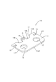
- FIG. 1 Perspective view of the electricity storage module of the embodiment Top view of the electricity storage module of the embodiment
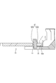
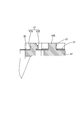
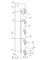
- the perspective view of the connection module of the embodiment Top view of the connection module of the embodiment A partially enlarged view of the frame R1 in FIG. Sectional view taken along the line AA of FIG. Sectional view taken along the line BB of FIG. Sectional view taken along the line CC of FIG.
- the perspective view of the bus bar of the embodiment Top view of the bus bar of the embodiment
- the top view of the flexible printed circuit board of embodiment The perspective view of the resin protector of the embodiment Top view of the resin protector of the embodiment Front view of the resin protector of the embodiment Rear view of the resin protector of the embodiment A partially enlarged view of the frame R2 in FIG.
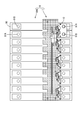
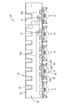
- connection module 1 of the present embodiment constitutes an electricity storage module M used as a drive source for vehicles such as electric vehicles and hybrid vehicles. As shown in FIG. 1, the connection module 1 is attached to a storage element group 90G in which a plurality of storage elements 90 are arranged in a line, and connects the plurality of storage elements 90 in series.
- the power storage element 90 is, for example, a secondary battery. As shown in FIG. 1, each power storage element 90 has a flat rectangular parallelepiped shape, and has an electrode placement surface 90F (upper surface in FIG. 1) perpendicular to a surface facing the adjacent power storage element 90. ing. Electrode terminals 91A and 91B are arranged on the electrode arrangement surface 90F. One of the electrode terminals 91A and 91B is the positive electrode terminal 91A, and the other is the negative electrode terminal 91B. Each of the electrode terminals 91A and 91B has a columnar shape, and although not shown in detail, the outer peripheral surface is threaded.
- a plurality of power storage elements 90 are arranged in a line to form a power storage element group 90G.
- the electrode terminals 91A and 91B of different polarities are adjacent to each other in the two power storage elements 90 adjacent to each other (that is, the positive electrode terminal 91A of one power storage element 90 and another adjacent to this).
- the negative electrode terminal 91B of the power storage element 90 is arranged adjacent to each other.
- the arrangement direction of the plurality of power storage elements 90 (lower left-upper right direction in FIG. 1) is the X-axis direction, and the direction along the surface of the power storage element 90 facing the adjacent power storage element 90 (in FIG. 1).
- the lower right-upper left direction will be described as the Y-axis direction, and the direction perpendicular to the electrode placement surface 90F (the vertical direction in FIG. 1) will be the Z-axis direction.
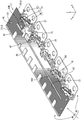
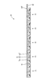
- connection module 1 is a member that is assembled to the surface (upper surface in FIG. 1) formed by the electrode placement surface 90F of each power storage element 90 in the power storage element group 90G. As shown in FIG. 3, the connection module 1 is connected to the flexible printed circuit board 20 (hereinafter referred to as “FPC 20”) and the FPC 20 to connect the positive electrode terminal 91 ⁇ / b> A and the negative electrode terminal 91 ⁇ / b> B of the adjacent power storage elements 90.
- FPC 20 flexible printed circuit board 20
- FIG. 1 A plurality of bus bars 10 (corresponding to a connecting member) and a resin protector 40 (corresponding to a holding member) that holds the bus bar 10 and the FPC 20 are provided.
- connection module 1 connected to one of the two columns of the electrode terminals 91A and 91B (lower right column) is illustrated, but the connection module 1 is similarly connected to the other column. 1 is connected.
- connection module 1 in the connection module 1, one bus bar 10 that connects the positive electrode terminal 91A at the right end and the negative electrode terminal 91B adjacent thereto is illustrated, and the other bus bars 10 are omitted. The same applies to FIG.
- Bus bar 10 Each of the plurality of bus bars 10 is made of metal, and as shown in FIGS. 9 and 10, an electrode connecting portion 11 that connects the positive electrode terminal 91A and the negative electrode terminal 91B of the adjacent power storage elements 90, and this electrode connection.
- An FPC connection piece 15 that is continuous from the portion 11 and is connected to the FPC 20 and a locking wall 16 that is continuous from the FPC connection piece 15 are provided.
- the electrode connection portion 11 is a rectangular plate-shaped portion as a whole, and has two electrode insertion holes 12 through which the electrode terminals 91A and 91B can be inserted, and two engagement recesses for engagement with the resin protector 40. 13 and 13.
- One electrode insertion hole 12 is arranged at a position close to one short side 11S of the electrode connecting portion 11, and one is arranged at a position close to the other short side 11S.
- One of the two engaging recesses 13 is a recess recessed from one short side 11S of the electrode connecting part 11, and the other is a recess recessed from the other short side 11S.
- the electrode connecting portion 11 has a connection recess 14 that is recessed from one long side 11LA of the pair of long sides 11LA and 11LB.
- the connection recess 14 is a recess defined by a first inner edge 14A parallel to the long side 11LA and a pair of first side edges 14B connecting both ends of the first inner edge 14A and the long side 11LA. ..
- the FPC connection piece 15 is a rectangular plate piece-shaped portion extending from the first inner edge 14A in the same plane as the electrode connection portion 11.
- the locking wall 16 is a short plate wall-shaped portion that extends vertically from the tip of the FPC connection piece 15.
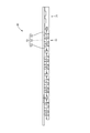
- the FPC 20 is a member for electrically connecting the plurality of bus bars 10 and the ECU (electronic control unit: not shown). Although not shown in detail, the FPC 20 has a plurality of conductive paths formed of copper foil. , And an insulating resin film that covers both surfaces of the conductive path. As shown in FIG. 11, the FPC 20 includes an FPC main body 21 (corresponding to a substrate main body) having a rectangular strip shape as a whole, a plurality of first movable portions 31 connected from the FPC main body 21, and a plurality of first movable portions 31. And a joining piece 35 joined to each of the plurality of bus bars 10.
- the FPC main body 21 has a first slit 22, a cutout portion 23, a plurality of positioning holes 24, and two engagement holes 25.
- the first slit 22 is provided at a substantially central position between the pair of long sides 21LA, 21LB of the FPC main body 21, parallel to the long sides 21LA, 21LB, and at both ends of the FPC main body 21 (a pair of short sides 21SA, 21SA). It is a slit that extends over almost the entire length except for a near portion.
- the notch 23 is a relatively wide gap that extends from the long side 21LA on one side (the lower side in FIG. 11) of the FPC main body 21 to the first slit 22, and is on one side of the FPC main body 21 (on the right side in FIG. 11). ) Is arranged near the short side 21SA.
- a part of the FPC body 21 sandwiched between the first slit 22 and the long side 21LA (a part below the first slit 22 in FIG. 11) is arranged on the short side 21SB side by the notch 23.
- the long first dividing portion 26 and the short second dividing portion 27 arranged on the short side 21SA side are divided.
- a plurality of positioning holes 24 are arranged at a position close to one short side 21SA, two at a position close to the other short side 21SB, and one at a substantially central position of the first dividing section 26.
- One of the two engaging holes 25 is arranged at a position close to the cutout portion 23 in the first dividing portion 26, and the other is arranged at a position close to the cutout portion 23 in the second dividing portion 27.
- the first movable portion 31 is composed of a linear spring-like portion (corresponding to a first spring portion) that is continuous from the FPC main body 21, extends from the long side 21LA of the FPC main body 21, and is curved in a U shape.
- the portion 32 (corresponding to the bending portion), the straight portion 33 continuous from the extending end of the first bending portion 32 and extending along the long side 21LA, and the straight portion 33 extending from the extending end of the straight portion 33 to the first bending portion 32.
- Has a second bending portion 34 (corresponding to a bending portion) that bends in a U shape in the opposite direction, and has a substantially S shape as a whole.
- the plurality of first movable portions 31 are arranged in a line along the long side 21LA, one of them is connected from the second dividing portion 27, and the rest are from the first dividing portion 26. It is in a row.
- the joining piece 35 is a rectangular plate piece-like portion that is continuous from the extended end of the second bending portion 34. A part of the conductive path is exposed as a bonding land (not shown) on one surface of the joining piece 35, and the FPC connecting piece 15 is connected thereto by soldering.
- the resin protector 40 is made of synthetic resin, and includes an FPC holding unit 41 (corresponding to a substrate holding unit) that holds the FPC main body 21, and a plurality of bus bar holding units 61 and 71 that hold the bus bar 10.
- the FPC holding portion 41 includes a holding plate portion 42 (corresponding to a holding body), side ribs 43 and center ribs 44A and 44B extending from the holding plate portion 42, a plurality of pressing pieces 45, and a plurality of holding pieces 45.
- the positioning protrusion 46 and the two FPC locking pieces 47 are provided.
- the holding plate portion 42 is in the form of a rectangular plate having substantially the same size as the FPC main body 21 as a whole.
- One surface (upper surface in FIG. 12) of the holding plate portion 42 is a mounting surface 42F on which the FPC main body 21 is mounted.
- the mounting surface 42F has side ribs 43, center ribs 44A and 44B, and pressing pieces. 45, a positioning protrusion 46, and an FPC locking piece 47 are arranged.
- the side rib 43 is a streak-like portion protruding from one long side 42LA (upper side in FIG. 12) of the pair of long sides 42LA, 42LB of the holding plate portion 42, and is arranged over substantially the entire length of the long side 42LA.
- the center ribs 44A and 44B are streak-shaped portions that extend parallel to the long sides 42LA and 42LB at a substantially central position between the pair of long sides 42LA and 42LB, and the pair of short sides 42SA and 42SB of the holding plate portion 42.
- One of the long sides is arranged near one of the short sides 42SA (on the left side of FIG. 12), and the other short side is arranged near the other short side 42SB.
- Each of the plurality of pressing pieces 45 is a plate piece-shaped portion extending from the side rib 43 in parallel with the holding plate portion 42, and the FPC main body 21 can be held between the holding plate portion 42 and the holding plate portion 42. ..
- Each of the plurality of positioning protrusions 46 is a circular protrusion extending from the holding plate portion 42, and is arranged at a position corresponding to each of the plurality of positioning holes 24 of the FPC main body 21.
- each of the two FPC locking pieces 47 includes a locking piece body 47A extending from the holding plate portion 42, and a locking protrusion 47B protruding from the tip of the locking piece body 47A.
- FPC main body 21 is arranged at a position corresponding to each of the two engagement holes 25.
- the holding plate portion 42 has a plurality of spring recesses 48 recessed inward from the other long side 42LB (corresponding to one edge). As shown in FIG. 16, the spring recess 48 includes a second inner edge 48A parallel to the long side 42LB and a pair of second side edges 48B connecting both ends of the second inner edge 48A and the long side 42LB. It is a defined recess.
- one that is closest to one short side 42SA of the holding plate portion 42 is the fixed bus bar holding portion 71, and the other is the second movable portion.
- a movable busbar holding portion 61 (corresponding to a connecting member holding portion) connected to the holding plate portion 42 via 51.
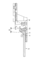
- the second movable portion 51 has a plate shape that is bent in a bellows shape as a whole, and is expandable / contractible in the direction along the long side 42LB of the holding plate portion 42. .. More specifically, the second movable portion 51 includes a plate-like spring connecting piece 52 (corresponding to a spring connecting portion) extending from the second inner edge 48A on the same plane as the holding plate portion 42, and the spring connecting portion. A pair of spring plate portions 53 (corresponding to a second spring portion) extending from the piece 52 along the second inner edge 48A while bending in opposite directions are provided.
- Each of the pair of spring plate portions 53 extends vertically from the extending end of the spring connecting piece 52 so as to be separated from the holding plate portion 42, is then folded back to extend toward the holding plate portion 42, and is further folded back. And has a S-shaped leaf spring shape extending away from the holding plate portion 42.
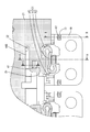
- the movable bus bar holding portion 61 includes a back plate portion 62 connected to the second movable portion 51, a bottom plate portion 63 (corresponding to a base portion) connected to the back plate portion 62, and an extension piece extending from the bottom plate portion 63. 65, a first bus bar locking piece 66 (corresponding to a locking portion), two second bus bar locking pieces 67 (corresponding to a locking portion), and a pair of abutting plates 68.
- the back plate portion 62 is a plate-shaped portion arranged in a posture perpendicular to the holding plate portion 42, and is connected to the respective tip portions of the pair of spring plate portions 53. There is.
- the bottom plate portion 63 is a plate-shaped portion that extends vertically from the back plate portion 62 in the direction opposite to the holding plate portion 42, and has two second slits 64. As shown in FIG. 13 and FIG. 16, each of the two second slits 64 extends from the extending end of the bottom plate portion 63 toward the back plate portion 62. 63 is divided into end plate portions 63A at both ends and a middle plate portion 63B at the center.
- the extension piece 65 is a plate piece-shaped portion that extends from the extension end of the bottom plate portion 63 on the same plane as the bottom plate portion 63.
- the first bus bar locking piece 66 extends from the middle plate portion 63B and is spaced from the back plate portion 62 by a first bending piece 66A (corresponding to a bending portion). ) And a first locking claw 66B (corresponding to a locking claw) projecting from the extension end of the first bending piece 66A in the direction opposite to the back plate portion 62.
- 66 A of 1st bending pieces incline slightly so that it separates from the back plate part 62, so that it separates from the intermediate plate part 63B.
- each of the two second bus bar locking pieces 67 includes a second bending piece 67A (corresponding to a bending portion) that extends vertically from the extending end of the two end plate portions 63A, and a second bending piece.
- a second locking claw 67B (corresponding to a locking claw) protruding from the tip of the piece 67A toward the back plate portion 62 is provided.
- each of the two abutting plates 68 is a plate-shaped portion that projects from the middle plate portion 63B along each slit edge of the two second slits 64, and is a back plate portion. It is arranged adjacent to 62.
- each movable busbar holding portion 61 with respect to the holding plate portion 42 is allowed to some extent by the second movable portion 51.
- the two spring plate portions 53 of the second movable portion 51 can be expanded and contracted to move in the direction along the long side 42LB of the holding plate portion 42 (X axis direction).
- the fixed bus bar holding portion 71 does not have the second movable portion 51, and the back bus portion 72 extends from the long side 42LB of the holding plate portion 42, except that the movable bus bar holding portion 71 extends. It has the same configuration as the holding portion 61.
- the same parts as those of the movable bus bar holding part 61 are designated by the same reference numerals, and the description thereof will be omitted.
- the fixed busbar holding portion 71, the movable busbar holding portion 61 adjacent to the fixed busbar holding portion 71, and the movable busbar holding portions 61 adjacent to each other are connected by a U-shaped leaf spring-like connecting portion 81 as shown in FIGS. 12 and 16. It is connected.
- the fixed busbar holding portion 71, the movable busbar holding portions 61 adjacent to the fixed busbar holding portion 71, and the movable busbar holding portions 61 adjacent to each other are arranged along the long side 42LB of the holding plate portion 42 (X-axis direction). It is possible to stably hold the plurality of busbars 10 that are assembled to the fixed busbar holding portion 71 and the movable busbar holding portion 61 by connecting without disturbing the displacement in the direction.
- connection module 1 An example of a procedure for assembling the connection module 1 having the above configuration will be described below.
- each bus bar 10 is in a state of being connected to the FPC body 21 via the first movable portion 31, and the first movable portion 31 is By being deformed, each bus bar 10 has a direction along the long side 21LA of the FPC main body 21 (X-axis direction), a direction approaching / separating from the FPC main body 21 (Y-axis direction), and a thickness of the FPC main body 21. It can be displaced to some extent in any direction (Z-axis direction).
- the joined body of the FPC 20 and the plurality of bus bars 10 is attached to the resin protector 40.
- the FPC main body 21 is attached to the FPC holding portion 41.
- the FPC main body 21 is placed on the holding plate portion 42 so as to be inserted into the gap between the holding plate portion 42 and the pressing piece 45, and the long side 21LB is set along the side rib 43.
- the FPC main body 21 is positioned on the holding plate portion 42 by inserting the positioning protrusions 46 into the positioning holes 24 and inserting the two center ribs 44A and 44B into the first slit 22. It Further, the FPC body 21 is pressed by the pressing piece 45 so as not to come off from the holding plate portion 42. As shown in FIG. 3 and FIG.
- each FPC engaging piece 47 is inserted into each engaging hole 25, and the engaging protrusion 47B engages with the FPC body 21, so that each dividing portion.
- the ends of 26 and 27 are pressed so that they do not turn up from the holding plate portion 42.
- each bus bar 10 is assembled to each bus bar holding portion 61, 71.
- Each of the second bus bar locking pieces 67 is inserted into each of the engaging recesses 13, the first bus bar locking piece 66 is bent by the locking wall 16, and the electrode connecting portion 11 is pushed toward the bottom plate portion 63.
- the first bus bar locking piece 66 elastically returns so that the locking wall 16 becomes the middle plate portion 63B and the first locking claw 66B. Sandwiched between.
- FIGS. 5 and 7 a portion of the electrode connecting portion 11 adjacent to the engaging recess 13 enters between the bottom plate portion 63 and the second locking claw 67B.
- each bus bar 10 is fixed to each bus bar holding portion 61, 71.
- the bus bar 10 can be easily assembled to the bus bar holding portions 61 and 71. It can be carried out. Further, since the busbar 10 can be easily assembled to the busbar holding portions 61 and 71 only by pushing the busbar 10 toward the bottom plate portion 63, the workability of assembling the connection module 1 is improved.
- the first bending portion 32 is arranged in the same plane as the FPC main body 21, and the linear portion 33 is the first portion, as shown in FIG. It is inclined so as to move away from the FPC main body 21 as it goes away from the bending portion 32.
- the second curved portion 34, the joint piece 35, and the bus bar 10 are arranged parallel to the FPC main body 21 and apart from the FPC main body 21.
- the linear portion 33 is passed through the gap between the first bus bar locking piece 66 and the back plate portion 62.
- the FPC main body 21 is held in a positioned state with respect to the FPC holding portion 41.
- each bus bar 10 is held in a positioned state by each movable bus bar holding portion 61.
- the bus bar 10 is displaceably connected to the FPC main body 21 by the first movable portion 31, and the movable bus bar holding portion 61 is displaceably connected to the FPC holding portion 41 by the second movable portion 51.
- the movable busbar holding portion 61 and the busbar 10 are assembled with each other, with respect to the FPC holding portion 41 and the FPC body 21, the long side 42LB of the holding plate portion 42 and the long side 21LA of the FPC body 21. Displacement in the direction along the axis (X-axis direction) is allowed.
- connection module 1 Assembly of Connection Module 1 to Storage Element Group 90G
- An example of a procedure for assembling the connection module 1 having the above configuration to the storage element group 90G will be described below.
- connection module 1 is arranged at a predetermined position on the storage element group 90G, and the electrode terminals 91A and 91B are inserted into the electrode insertion holes 12 of each bus bar 10. Then, the electrode terminals 91A and 91B are connected to the bus bar 10 by screwing nuts (not shown) to the electrode terminals 91A and 91B.
- the storage element group 90G configured by arranging a large number of storage elements 90 has a dimensional tolerance due to a dimensional error in manufacturing each storage element 90, an assembly error in a plurality of storage elements 90, and the like.
- the electrode terminals 91A and 91B may be displaced in a direction along the arrangement direction of the power storage elements 90 (X-axis direction).
- the electrodes caused by the dimensional tolerance of the storage element group 90G can be displaced according to the positional displacement of the terminals 91A and 91B and assembled to the electrode terminals 91A and 91B.
- each movable busbar holding portion 61 is referenced to the fixed busbar holding portion 71.
- it is displaced in the direction in which the fixed bus bar holding portion 71 is approached (the direction along the long side 42LB of the holding plate portion 42: the direction from the upper right to the lower left in FIG. 1).
- the fixed bus bar holding portion 71 located at one end of the resin protector 50 as a reference, the movable bus bar holding portion 61 located next to the fixed bus bar holding portion 71 and the interval between the adjacent movable bus bar holding portions 61 are narrow.
- the movable bus bar holding portion 61 is displaced so that Accordingly, with respect to one bus bar 10 held by the fixed bus bar holding portion 71, the other bus bar 10 is displaced so that the distance between the adjacent bus bars 10 becomes small, and the displacement of the electrode terminals 91A and 91B is dealt with. can do.
- each movable busbar holding portion 61 is referenced to the fixed busbar holding portion 71.
- it is displaced in the direction away from the fixed bus bar holding portion 71 (the direction along the long side 42LB of the holding plate portion 42: the direction from the lower left to the upper right in FIG. 1).
- the fixed busbar holding portion 71 located at one end of the resin protector 50 as a reference, the movable busbar holding portion 61 located next to the fixed busbar holding portion 71 and the interval between the adjacent movable busbar holding portions 61 are wide.
- the movable bus bar holding portion 61 is displaced so that As a result, one bus bar 10 held by the fixed bus bar holding portion 71 is used as a reference to displace another bus bar 10 so that the distance between the adjacent bus bars 10 becomes large, and the displacement of the electrode terminals 91A and 91B is dealt with. can do.
- connection module 1 it is possible to avoid difficulty in assembling the connection module 1 to the electricity storage element group 90G due to the dimensional tolerance of the electricity storage element group 90G, and improve the assembling workability.
- the shape of the flexible FPC 20 is kept constant, and the FPC 20 and the plurality of bus bars 10 are collectively placed at a predetermined position on the storage element group 90G. Since it can be set, assembly workability can be improved.
- the connection module 1 is a module that is attached to the storage element group 90G configured by the plurality of storage elements 90 including the electrode terminals 91A and 91B to connect the plurality of storage elements 90.
- the FPC 20 is provided with a plurality of bus bars 10 connected to the FPC 20 and connecting the electrode terminals 91A and 91B of the adjacent power storage elements 90 to each other, and the resin protector 40 holding the bus bar 10 and the FPC 20.
- the FPC 20 includes an FPC main body 21, and a first movable portion 31 that connects the FPC main body 21 and the bus bar 10, and the resin protector 40 includes an FPC holding portion 41 to which the FPC main body 21 is fixed and the bus bar 10.
- a movable busbar holding portion 61 that is fixed, and a plurality of second movable portions 51 that connect the FPC holding portion 41 and the movable busbar holding portion 61.
- the first movable portion 31 and the second movable portion 51 connect the busbar 10 and the movable busbar holding portion 61 to the FPC main body 21 and the FPC holding portion 41 while allowing displacement.
- the displacement of the bus bar 10 and the movable bus bar holding portion 61 relative to the FPC main body 21 and the FPC holding portion 41 is allowed in the assembled state. It is possible to avoid the difficulty of assembling the connection module 1 to the power storage element group 90G due to the positional displacement of the electrode terminals 91A and 91B caused by, and to improve the assembling workability. Further, by holding the FPC 20 and the plurality of bus bars 10 on the resin protector 40, the shape of the flexible FPC 20 is held constant, and the FPC 20 and the plurality of bus bars 10 are collectively placed at a predetermined position of the storage element group 90G. Since it can be set, assembly workability can be improved.
- the first movable portion 31 is constituted by a wire spring extending from the FPC main body 21 and having a first bending portion 32 and a second bending portion 34.
- the bus bar 10 can be connected to the FPC main body 21 while allowing the displacement with a simple configuration.
- the bus bar 10 can be arranged in any of a direction in which it approaches and separates from the FPC body 21, a thickness direction of the FPC body 21, and a direction along the FPC body 21.
- it can be freely displaced to some extent, it is possible to easily perform the assembling work when assembling the resin protector 40 after the bus bar 10 is connected to the FPC 20.
- the plurality of second movable portions 51 are arranged side by side along the long side 42LB of the FPC holding portion 41, and each of the plurality of second movable portions 51 is expandable / contractible in the direction along the long side 42LB.
- the spring plate portion 53 is provided.
- the second movable portion 51 allows the movable busbar holding portion 61 to be displaced in the direction along the long side 42LB of the FPC holding portion 41. Therefore, by attaching the connection module 1 to the storage element group 90G so that the long side 42LB of the FPC holding portion 41 extends along the arrangement direction of the plurality of storage elements 90, the movable busbar holding portion 61 and this movable busbar holding portion are held. Displacement of the bus bar 10 held by the portion 61 in the direction along the arrangement direction of the power storage element group 90G is allowed.
- connection module 1 it is possible to avoid the difficulty of assembling the connection module 1 to the power storage element group 90G due to the positional deviation of the electrode terminals 91A and 91B due to the dimensional tolerance of the power storage element group 90G, and to improve the workability of assembly. it can.
- the resin protector 50 may include a connecting portion 81 that connects the adjacent movable busbar holding portions 61 while allowing the displacement of the holding plate portion 42 of the FPC holding portion 41 in the direction along the long side 42LB. Absent.
- the movable busbar holding portions 61 are connected to each other without hindering the displacement of the movable busbar holding portions 61 in the direction along the arrangement direction of the storage element groups 90G, and the plurality of busbars 10 are stabilized. Can be held.
- the FPC holding portion 41 is arranged with a holding plate portion 42 arranged along the FPC main body 21 and a gap with respect to the holding plate portion 42, and holds the FPC main body 21 between the holding plate portion 42 and the holding plate portion 42.
- a pressing piece 45 for controlling.
- the FPC main body 21 has a positioning hole 24, and the FPC holding portion 41 is inserted through the holding plate portion 42 arranged along the FPC main body 21 and the holding plate portion 42 into the positioning hole 24.
- the positioning protrusion 46 is provided for positioning the FPC main body 21 with respect to the holding plate portion 42.
- the FPC main body 21 can be positioned in the FPC holding unit 41 with a simple configuration.
- the movable busbar holding portion 61 includes a bottom plate portion 63 arranged along the busbar 10, and a first busbar locking piece 66 and a second busbar locking piece 67 connected from the bottom plate portion 63.
- the first bus bar locking piece 66 is projectingly provided from the bottom plate portion 63, and holds the bus bar 10 by sandwiching the bus bar 10 between the bendable first bending piece 66A and the first bending piece 66A protruding from the bottom plate portion 63.
- the first locking claw 66B is provided.
- the second busbar locking piece 67 is provided so as to project from the bottom plate portion 63, and the busbar 10 is sandwiched between the second bending piece 67A that is bendable and the bottom plate portion 63 that projects from the second bending piece 67A. And a second locking claw 67B that holds the same.
- the busbar 10 can be easily assembled to the movable busbar holding portion 61 simply by pushing the busbar 10 toward the bottom plate portion 63, so that the workability of assembling the connection module 1 is improved.
- the first movable portion 31 includes the first bending portion 32 and the second bending portion 34, but the number of bending portions may be one or three or more.
- the second movable portion 51 includes the pair of spring plate portions 53 that are bent in a bellows shape.
- the shape of the second spring portion is not limited to that in the above-described embodiment, and one of the substrate holding portions is used. It suffices to have a spring shape that can expand and contract in the direction along the edge.
- the two spring plate portions 53 of the second movable portion 51 have a symmetrical shape with the spring connection piece 52 interposed therebetween, but the pair of second spring portions have an asymmetrical shape. May have.
- Connection module 10 ... Bus bar (connection member) 20 ... Flexible printed circuit board 21 ... FPC body (board body) 24 ... Positioning hole 31 ... 1st movable part (1st spring part) 32 ... 1st bending part (bending part) 34 ... 2nd bending part (bending part) 40 ... Resin protector (holding member) 41 ... FPC holding unit (board holding unit) 42 ... Holding plate part (holding body) 45 ... Pressing piece 46 ... Positioning projection 51 ... Second movable part 53 ... Spring plate part (second spring part) 61 ... Movable busbar holder (connecting member holder) 63 ... Bottom plate (base) 66 ... First bus bar locking piece (locking portion) 66A ...
Landscapes
- Chemical & Material Sciences (AREA)
- Chemical Kinetics & Catalysis (AREA)
- Electrochemistry (AREA)
- General Chemical & Material Sciences (AREA)
- Engineering & Computer Science (AREA)
- Aviation & Aerospace Engineering (AREA)
- Microelectronics & Electronic Packaging (AREA)
- Manufacturing & Machinery (AREA)
- Coupling Device And Connection With Printed Circuit (AREA)
- Connection Of Batteries Or Terminals (AREA)
Priority Applications (3)
| Application Number | Priority Date | Filing Date | Title |
|---|---|---|---|
| US17/296,089 US12418078B2 (en) | 2018-11-22 | 2019-11-01 | Connection module |
| CN202410187852.XA CN117996364A (zh) | 2018-11-22 | 2019-11-01 | 柔性印刷基板以及连接模块 |
| CN201980073359.2A CN112997354B (zh) | 2018-11-22 | 2019-11-01 | 连接模块 |
Applications Claiming Priority (2)
| Application Number | Priority Date | Filing Date | Title |
|---|---|---|---|
| JP2018-219298 | 2018-11-22 | ||
| JP2018219298A JP7212504B2 (ja) | 2018-11-22 | 2018-11-22 | 接続モジュール |
Publications (1)
| Publication Number | Publication Date |
|---|---|
| WO2020105400A1 true WO2020105400A1 (ja) | 2020-05-28 |
Family
ID=70773176
Family Applications (1)
| Application Number | Title | Priority Date | Filing Date |
|---|---|---|---|
| PCT/JP2019/043017 Ceased WO2020105400A1 (ja) | 2018-11-22 | 2019-11-01 | 接続モジュール |
Country Status (4)
| Country | Link |
|---|---|
| US (1) | US12418078B2 (enExample) |
| JP (1) | JP7212504B2 (enExample) |
| CN (2) | CN112997354B (enExample) |
| WO (1) | WO2020105400A1 (enExample) |
Cited By (6)
| Publication number | Priority date | Publication date | Assignee | Title |
|---|---|---|---|---|
| WO2022163420A1 (ja) * | 2021-02-01 | 2022-08-04 | 株式会社オートネットワーク技術研究所 | 配線モジュール |
| US20220304158A1 (en) * | 2021-03-18 | 2022-09-22 | Samsung Sdi Co., Ltd. | Hybrid circuit board and battery pack having same |
| CN115332732A (zh) * | 2021-05-10 | 2022-11-11 | 矢崎总业株式会社 | 汇流条模块 |
| CN115911762A (zh) * | 2021-08-06 | 2023-04-04 | 矢崎总业株式会社 | 汇流条 |
| US20230261333A1 (en) * | 2020-07-14 | 2023-08-17 | Autonetworks Technologies, Ltd. | Wiring module |
| US12506227B2 (en) * | 2020-07-14 | 2025-12-23 | Autonetworks Technologies, Ltd. | Wiring module |
Families Citing this family (18)
| Publication number | Priority date | Publication date | Assignee | Title |
|---|---|---|---|---|
| JP7403240B2 (ja) | 2019-06-07 | 2023-12-22 | 日本メクトロン株式会社 | 配線材及びバッテリモジュール |
| JP2020205176A (ja) * | 2019-06-17 | 2020-12-24 | 矢崎総業株式会社 | 回路体、基板と回路体との接続構造、及び、バスバモジュール |
| CN210467965U (zh) * | 2019-09-23 | 2020-05-05 | 宁德时代新能源科技股份有限公司 | 电池模组、电池包以及车辆 |
| JP6810946B1 (ja) | 2020-02-12 | 2021-01-13 | 国立研究開発法人農業・食品産業技術総合研究機構 | トバモウイルス抵抗性トマト植物、トバモウイルス抵抗性トマト植物の生産方法、トマト植物におけるトバモウイルス抵抗性の付与方法、トバモウイルス抵抗性トマト植物のスクリーニング方法およびトマト植物におけるトバモウイルス抵抗性の検出方法 |
| JP7567448B2 (ja) * | 2020-07-14 | 2024-10-16 | 株式会社オートネットワーク技術研究所 | 配線モジュール |
| JP7186760B2 (ja) * | 2020-12-21 | 2022-12-09 | プライムプラネットエナジー&ソリューションズ株式会社 | 蓄電モジュール |
| JP7253525B2 (ja) * | 2020-12-21 | 2023-04-06 | プライムプラネットエナジー&ソリューションズ株式会社 | 蓄電モジュール |
| CN113316314B (zh) * | 2021-07-28 | 2021-11-19 | 中航锂电科技有限公司 | 柔性电路器件及其制备方法、电池装置 |
| CN115708253B (zh) * | 2021-08-18 | 2025-11-18 | 莫列斯有限公司 | 电池连接模组 |
| CA3241983A1 (en) * | 2022-01-03 | 2023-07-06 | Jason D. Fuhr | Intelligent battery and assembly method |
| CN216872203U (zh) * | 2022-02-07 | 2022-07-01 | 宁德时代新能源科技股份有限公司 | 线路板采样结构、电池模组、电池包及用电设备 |
| JP7737612B2 (ja) * | 2022-03-16 | 2025-09-11 | 株式会社オートネットワーク技術研究所 | 配線モジュール |
| CN114725630A (zh) * | 2022-03-30 | 2022-07-08 | 中创新航科技股份有限公司 | 电池装置 |
| WO2023201083A2 (en) * | 2022-04-14 | 2023-10-19 | Cps Technology Holdings Llc | Intelligent battery systems, components for intelligent battery systems, methods of manufacturing and operating intelligent battery systems and components of the same |
| JP7617877B2 (ja) * | 2022-09-05 | 2025-01-20 | プライムプラネットエナジー&ソリューションズ株式会社 | 電池モジュール |
| WO2024145246A2 (en) * | 2022-12-28 | 2024-07-04 | Cps Technology Holdings Llc | Lead assembly for battery cell monitoring |
| US20240332758A1 (en) * | 2023-03-27 | 2024-10-03 | Samsung Sdi Co., Ltd. | Battery pack and method of manufacturing the battery pack |
| CN220604904U (zh) * | 2023-07-24 | 2024-03-15 | 惠州亿纬锂能股份有限公司 | 一种ccs连接片、ccs采集回路和电池包 |
Citations (4)
| Publication number | Priority date | Publication date | Assignee | Title |
|---|---|---|---|---|
| JP2013143281A (ja) * | 2012-01-11 | 2013-07-22 | Auto Network Gijutsu Kenkyusho:Kk | 電池用配線モジュール |
| JP2015022965A (ja) * | 2013-07-22 | 2015-02-02 | 株式会社デンソー | 組電池 |
| JP2015049931A (ja) * | 2013-08-29 | 2015-03-16 | 古河電気工業株式会社 | 電池パックの電池内配線モジュール |
| JP2015185226A (ja) * | 2014-03-20 | 2015-10-22 | 愛三工業株式会社 | バスバーモジュール |
Family Cites Families (11)
| Publication number | Priority date | Publication date | Assignee | Title |
|---|---|---|---|---|
| JP3625577B2 (ja) | 1996-06-20 | 2005-03-02 | 三洋電機株式会社 | プリント基板を内蔵するパック電池 |
| KR20120003432A (ko) * | 2009-03-31 | 2012-01-10 | 산요덴키가부시키가이샤 | 전지 모듈, 배터리 시스템 및 전동 차량 |
| JP2013080620A (ja) * | 2011-10-04 | 2013-05-02 | Auto Network Gijutsu Kenkyusho:Kk | 電池用配線モジュール |
| JP6257889B2 (ja) | 2012-10-23 | 2018-01-10 | 日本メクトロン株式会社 | バスバー付きフレキシブルプリント配線板およびその製造方法、並びにバッテリシステム |
| JP5949796B2 (ja) | 2014-01-22 | 2016-07-13 | トヨタ自動車株式会社 | 接続ユニット |
| EP3321994B1 (en) | 2015-07-09 | 2023-03-08 | Vehicle Energy Japan Inc. | Cell module |
| JP6533500B2 (ja) * | 2016-08-12 | 2019-06-19 | 矢崎総業株式会社 | バスバモジュール及び電池パック |
| KR102429345B1 (ko) * | 2016-12-23 | 2022-08-04 | 삼성전자주식회사 | 피씨엠 케이스 및 그것을 포함하는 전자 장치 |
| CN109301634B (zh) | 2017-07-24 | 2020-06-19 | 莫仕连接器(成都)有限公司 | 电池连接模块 |
| CN207779574U (zh) * | 2018-01-31 | 2018-08-28 | 长城汽车股份有限公司 | 用于电池的温感器安装组件及电池 |
| EP3595035A1 (en) * | 2018-07-10 | 2020-01-15 | Yazaki Corporation | Connector-equipped circuit body and bus bar module |
-
2018
- 2018-11-22 JP JP2018219298A patent/JP7212504B2/ja active Active
-
2019
- 2019-11-01 CN CN201980073359.2A patent/CN112997354B/zh active Active
- 2019-11-01 US US17/296,089 patent/US12418078B2/en active Active
- 2019-11-01 WO PCT/JP2019/043017 patent/WO2020105400A1/ja not_active Ceased
- 2019-11-01 CN CN202410187852.XA patent/CN117996364A/zh active Pending
Patent Citations (4)
| Publication number | Priority date | Publication date | Assignee | Title |
|---|---|---|---|---|
| JP2013143281A (ja) * | 2012-01-11 | 2013-07-22 | Auto Network Gijutsu Kenkyusho:Kk | 電池用配線モジュール |
| JP2015022965A (ja) * | 2013-07-22 | 2015-02-02 | 株式会社デンソー | 組電池 |
| JP2015049931A (ja) * | 2013-08-29 | 2015-03-16 | 古河電気工業株式会社 | 電池パックの電池内配線モジュール |
| JP2015185226A (ja) * | 2014-03-20 | 2015-10-22 | 愛三工業株式会社 | バスバーモジュール |
Cited By (11)
| Publication number | Priority date | Publication date | Assignee | Title |
|---|---|---|---|---|
| US20230261333A1 (en) * | 2020-07-14 | 2023-08-17 | Autonetworks Technologies, Ltd. | Wiring module |
| US12506227B2 (en) * | 2020-07-14 | 2025-12-23 | Autonetworks Technologies, Ltd. | Wiring module |
| WO2022163420A1 (ja) * | 2021-02-01 | 2022-08-04 | 株式会社オートネットワーク技術研究所 | 配線モジュール |
| US20220304158A1 (en) * | 2021-03-18 | 2022-09-22 | Samsung Sdi Co., Ltd. | Hybrid circuit board and battery pack having same |
| CN115119396A (zh) * | 2021-03-18 | 2022-09-27 | 三星Sdi株式会社 | 混合电路板和具有其的电池组 |
| EP4071904A1 (en) * | 2021-03-18 | 2022-10-12 | Samsung SDI Co., Ltd. | Hybrid circuit board and battery pack having same |
| CN115332732A (zh) * | 2021-05-10 | 2022-11-11 | 矢崎总业株式会社 | 汇流条模块 |
| EP4089787A1 (en) * | 2021-05-10 | 2022-11-16 | Yazaki Corporation | Busbar module |
| CN115332732B (zh) * | 2021-05-10 | 2024-05-24 | 矢崎总业株式会社 | 汇流条模块 |
| US12261401B2 (en) | 2021-05-10 | 2025-03-25 | Yazaki Corporation | Busbar module |
| CN115911762A (zh) * | 2021-08-06 | 2023-04-04 | 矢崎总业株式会社 | 汇流条 |
Also Published As
| Publication number | Publication date |
|---|---|
| US12418078B2 (en) | 2025-09-16 |
| CN112997354A (zh) | 2021-06-18 |
| CN117996364A (zh) | 2024-05-07 |
| CN112997354B (zh) | 2024-02-23 |
| JP7212504B2 (ja) | 2023-01-25 |
| JP2020087665A (ja) | 2020-06-04 |
| US20220013868A1 (en) | 2022-01-13 |
Similar Documents
| Publication | Publication Date | Title |
|---|---|---|
| CN112997354B (zh) | 连接模块 | |
| JP6986504B2 (ja) | 接続モジュール | |
| JP6691178B2 (ja) | プロテクタ、及び、バスバモジュール | |
| JP7041098B2 (ja) | バスバモジュール | |
| JP6533500B2 (ja) | バスバモジュール及び電池パック | |
| JP2010055885A (ja) | 電源装置 | |
| JP2013105571A (ja) | 電池配線モジュール | |
| JP6145314B2 (ja) | バスバモジュール及び電源装置 | |
| WO2020071069A1 (ja) | フレキシブルプリント基板、及び配線モジュール | |
| CN112997355B (zh) | 连接模块 | |
| CN112106221B (zh) | 连接模块及蓄电模块 | |
| JP7308328B2 (ja) | 接続モジュール | |
| JP6985240B2 (ja) | 接続モジュール | |
| JP2025077790A (ja) | 接続モジュールセット、電極接続部材セット、および電池パック | |
| CN116097381B (zh) | 车载用配线模块及柔性基板 | |
| US20250149760A1 (en) | Wiring module and battery pack | |
| US20250149723A1 (en) | Wiring module and battery pack | |
| WO2024122238A1 (ja) | 積層回路体、及び、バスバモジュール | |
| JP2025035338A (ja) | バスバー及び配線モジュール | |
| KR20220049625A (ko) | 용량 가변 적응형 배터리 모듈의 결합 구조 | |
| JP2011250613A (ja) | 回路構成体 |
Legal Events
| Date | Code | Title | Description |
|---|---|---|---|
| 121 | Ep: the epo has been informed by wipo that ep was designated in this application |
Ref document number: 19887153 Country of ref document: EP Kind code of ref document: A1 |
|
| NENP | Non-entry into the national phase |
Ref country code: DE |
|
| 122 | Ep: pct application non-entry in european phase |
Ref document number: 19887153 Country of ref document: EP Kind code of ref document: A1 |
|
| WWG | Wipo information: grant in national office |
Ref document number: 17296089 Country of ref document: US |