WO2020105213A1 - 走査型プローブ顕微鏡および走査型プローブ顕微鏡の光軸調整方法 - Google Patents
走査型プローブ顕微鏡および走査型プローブ顕微鏡の光軸調整方法Info
- Publication number
- WO2020105213A1 WO2020105213A1 PCT/JP2019/026489 JP2019026489W WO2020105213A1 WO 2020105213 A1 WO2020105213 A1 WO 2020105213A1 JP 2019026489 W JP2019026489 W JP 2019026489W WO 2020105213 A1 WO2020105213 A1 WO 2020105213A1
- Authority
- WO
- WIPO (PCT)
- Prior art keywords
- sample
- cantilever
- optical axis
- laser light
- mirror
- Prior art date
- Legal status (The legal status is an assumption and is not a legal conclusion. Google has not performed a legal analysis and makes no representation as to the accuracy of the status listed.)
- Ceased
Links
Images


Classifications
-
- G—PHYSICS
- G01—MEASURING; TESTING
- G01Q—SCANNING-PROBE TECHNIQUES OR APPARATUS; APPLICATIONS OF SCANNING-PROBE TECHNIQUES, e.g. SCANNING PROBE MICROSCOPY [SPM]
- G01Q20/00—Monitoring the movement or position of the probe
- G01Q20/02—Monitoring the movement or position of the probe by optical means
Definitions
- the present invention relates to a scanning probe microscope and an optical axis adjusting method for the scanning probe microscope.
- the scanning probe microscope uses a cantilever with a probe called a cantilever.
- a change in the warp or vibration of the cantilever is converted into a change in the reflected light of the laser applied to the back surface of the cantilever and detected by a photodetector.
- the photodetector detects changes in the position, intensity, phase, etc. of the reflected light and converts it into various physical information (for example, refer to Patent Document 1 (JP 2000-346782 A)).
- an object of the present invention is to provide a scanning probe microscope and an optical axis adjusting method for a scanning probe microscope that can easily adjust the optical axis.
- a scanning probe microscope is a cantilever having a probe at the tip, an optical system that irradiates the cantilever with laser light at the time of measurement, and detects the laser light reflected by the cantilever, and the laser light
- An optical axis adjustment unit that adjusts the optical axis of the laser beam based on the detected position, and a sample holding unit that holds the sample are provided.
- the sample holder includes a mirror.
- the sample holder includes a sample table mountable on the upper side of the mirror. This prevents the mirror from being damaged by placing the sample directly on the mirror.
- a gap is formed between the mirror and the sample table. This can further prevent the mirror from being damaged.
- the sample table is made of metal, and the sample holder further has a magnet arranged below the mirror.
- the scanning probe microscope comprises a scanner.
- the sample holder is composed of an attachment that can be attached to the scanner and a sample table.
- a mirror is formed on the top surface of the attachment.
- a magnet is embedded inside the attachment.
- the scanner is formed with a cylindrical fitting hole.
- the attachment has a disc-shaped upper surface and a cylindrical protrusion.
- the protrusion is configured to be insertable into the insertion hole.
- the scanning probe microscope is a cantilever having a probe at the tip, and at the time of measurement, the cantilever is irradiated with laser light and the laser light reflected by the cantilever is detected.
- an optical system a scanner for moving the sample, and a sample holder for holding the sample.
- the sample holder can be attached to the scanner, includes an attachment including a magnet formed on the upper surface and a magnet embedded therein, and a mountable sample holder that can be mounted on the mirror.
- the optical axis adjustment method includes the steps of setting the sample stand on the mirror, placing the laser beam on the optical system, photographing the range including the position of the tip of the cantilever, and photographing.
- the method includes the steps of detecting the position of the tip of the probe and the position of the spot of the laser light from the generated image, and adjusting the optical axis of the laser light based on the detected position.
- the optical axis can be adjusted without disposing a sample with a high reflectance different from the observation target.
- the optical axis can be easily adjusted.
- FIG. 3 is a diagram showing a probe 7, a cantilever 2 and a holder 15.
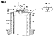
- FIG. 3 is a vertical cross-sectional view of an upper portion of a scanner 43 and a sample holder 44 when observing a sample in the scanning probe microscope 1.
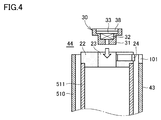
- FIG. 6 is a diagram illustrating a state before the stub type attachment 30 included in the sample holding unit 44 is attached to the scanner 43.
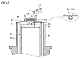
- FIG. 6 is a vertical cross-sectional view of the upper portion of the scanner 43 when the optical axis is adjusted in the scanning probe microscope 1.
- 3 is a diagram illustrating an example of a hardware configuration of an image processing unit 72 and an optical axis adjusting unit 73.
- the spot of the cantilever and the beam of the laser light is observed with an imaging unit such as an optical microscope or CCD (Charge Coupled Device), and the optical spot is irradiated onto the back surface of the cantilever. It is conceivable to automatically move the laser light source or the cantilever.
- an imaging unit such as an optical microscope or CCD (Charge Coupled Device)
- CCD Charge Coupled Device
- the inventor of the present application has studied a configuration and a method capable of automatically adjusting the optical axis without arranging a sample or a mirror having a high reflectance different from that of an observation target when adjusting the optical axis.
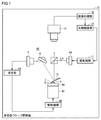
- FIG. 1 is a diagram showing a configuration of a scanning probe microscope 1 of the embodiment.
- the scanning probe microscope 1 according to the embodiment includes a photographing unit 10, an image processing unit 72, an optical axis adjusting unit 73, an optical system 80, a cantilever 2, a measuring unit 14, a drive mechanism 49, a scanner 43, and a scanning unit 43.
- the sample holding unit 44 and the drive mechanism 11 are provided.
- the cantilever 2 has a probe 7 at the free end of the surface.
- the sample S is arranged so as to face the probe 7.
- the cantilever 2 is displaced by the interatomic force (attractive force or repulsive force) between the probe 7 and the sample S.
- the sample S is placed on the sample holder 44.
- the optical system 80 irradiates the back surface of the cantilever 2 with laser light at the time of measurement, and detects the laser light reflected on the back surface of the cantilever 2.
- the optical system 80 can detect the deflection of the cantilever 2.
- the optical system 80 includes a laser light source 60, a beam splitter 3 that is a first mirror, a reflecting mirror 4 that is a second mirror, and a photodetector 5.
- the laser light source 60 is composed of a laser oscillator or the like that emits laser light.
- the photodetector 5 is composed of a photodiode or the like that detects incident laser light.
- the laser light emitted from the laser light source 60 is reflected by the beam splitter 3 and enters the cantilever 2.
- the laser light is reflected by the cantilever 2, is further reflected by the reflecting mirror 4, and is incident on the photodetector 5.
- the displacement of the cantilever 2 can be measured by the photodetector 5 detecting the
- the drive mechanism 11 adjusts the optical axis of the laser light by changing the position of the laser light source 60.
- the measuring unit 14 measures the characteristics of the sample S based on the displacement of the cantilever 2 obtained by the change in the position of the laser beam detected by the optical system 80. For example, the measuring unit 14 creates a force curve or the like that represents the time change of the acting force (force) from the time change of the displacement of the cantilever 2.
- the measurement unit 14 sends a control signal for driving the scanner 43 to the drive mechanism 49.
- the drive mechanism 49 drives the scanner 43 to change the relative positional relationship between the sample S mounted on the scanner 43 and the probe 7.
- the photographing unit 10 photographs a range including the position of the probe 7 when adjusting the optical axis of the laser light.
- the imaging unit 10 is composed of an optical microscope, a CCD camera, a CMOS (Complementary Metal Oxide Semiconductor) camera, and the like.
- the scanner 43 is driven in a three-dimensional direction by the drive mechanism 49.
- the scanner 43 is composed of a piezo element that is deformed by a voltage applied from the outside.
- the sample holder 44 mounts the sample S thereon.
- the sample holder 44 is configured to be attachable to the scanner 43.
- the image processing unit 72 identifies the position of the spot SP of the laser light and the position of the tip TP of the cantilever 2 based on the captured image output from the capturing unit 10.
- the optical axis adjusting unit 73 changes the position of the laser light source 60 by controlling the drive mechanism 11 based on the position of the spot SP of the laser light and the position of the tip of the cantilever identified by the image processing unit 72. To adjust the optical axis.
- FIG. 2 is a diagram showing the probe 7, the cantilever 2, and the holder 15. As shown in FIG. 2, the probe 7 is attached to the tip of the cantilever 2.
- the holder 15 is a member that supports the cantilever 2.
- FIG. 3 is a vertical cross-sectional view of the upper part of the scanner 43 and the sample holder 44 when observing the sample in the scanning probe microscope 1.
- FIG. 4 is a diagram showing a state before the stub type attachment 30 included in the sample holder 44 is attached to the scanner 43.
- FIG. 5 is a vertical cross-sectional view of the upper portion of the scanner 43 when the optical axis is adjusted in the scanning probe microscope 1.
- a substantially donut-shaped pedestal portion 22 having a cylindrical insertion hole 23 is fixed to the upper end surface of the piezo tube 511 of the scanner 43.
- a fixing screw 24 is screwed into the peripheral surface of the pedestal portion 22 in the horizontal direction, and a notch 101 is formed in the scanner housing 510 so that the fixing screw 24 can be turned from the lateral direction.
- the sample holder 44 includes the stub type attachment 30 and a sample table 52.
- the stub type attachment 30 has a convex portion 31 formed below and a disc-shaped mirror 33 formed on the upper surface.
- the stub type attachment 30 has a magnet 32 embedded therein.
- the stub type attachment 30 is made of aluminum.
- the convex portion 31 of the stub type attachment 30 is inserted into the insertion hole 23 of the pedestal portion 22.
- the stub type attachment 30 can be fixed to the pedestal 22 by tightening the fixing screw 24.
- the sample S can be placed on the sample table 52.
- the sample table 52 is made of metal and has a disk shape.
- the sample table 52 When observing the sample, the sample table 52 is placed above the mirror 33.
- the sample table 52 can be fixed by the attraction force of the magnet 32 in the stub type attachment 30.
- a gap 38 is formed between the mirror 33 and the sample table 52. This prevents the sample table 52 from damaging the mirror 33.
- the sample table 52 is not placed on the mirror 33 when adjusting the optical axis.
- the laser light is incident on the mirror 33 without being blocked by the sample table 52, and the reflected laser light is incident on the imaging unit 10 without being blocked by the sample table 52.
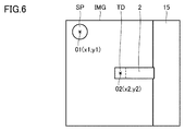
- FIG. 6 is a diagram illustrating an example of the captured image IMG.
- the captured image IMG includes the tip TP of the cantilever 2 and the spot SP of the beam of laser light. From the position (x1, y1) of the pixel at the center O1 of the spot SP of the laser beam and the position (x2, y2) of the pixel at the center O2 of the tip TP of the cantilever 2, the center O1 of the spot SP of the laser beam. However, since it coincides with the center O2 of the tip TP of the cantilever 2, the moving direction and the moving amount of the laser light source 60 can be specified.
- FIG. 7 is a flowchart showing a procedure for adjusting the optical axis of the laser light according to the embodiment. This optical axis adjustment is performed, for example, when the cantilever 2 is replaced and before the physical properties of the sample S are measured.
- step S101 the sample table 52 is not placed on the mirror 33 of the stub type attachment 30.
- step S102 the laser light source 60 emits laser light.
- step S103 the photographing unit 10 photographs the range included in the tip of the cantilever 2.
- step S104 the image processing unit 72 determines the position (x1, y1) of the pixel at the center O1 of the spot SP of the laser light in the captured image output from the imaging unit 10 and the pixel at the center O2 of the tip TP of the cantilever 2.
- the position (x2, y2) is specified.
- step S105 the optical axis adjusting unit 73 determines, based on (x1, y1) and (x2, y2), that the position of the center O1 of the spot SP of the laser light is the position of the cantilever 2 to which the probe 7 is attached.
- a control signal for controlling the drive mechanism 11 to move the laser light source 60 is output so as to match the position of the center O2 of the tip.
- the drive mechanism 11 adjusts the optical axis of the laser light by changing the position of the laser light source 60 according to the control signal.
- the sample stage 52 when the optical axis of the laser beam is adjusted, the sample stage 52 is removed so that the laser beam is incident on the mirror 33 and reflected. With this, the laser spot can be detected by the imaging unit, so that it is possible to save the trouble of disposing a sample or a mirror having a high reflectance different from that of the observation target when adjusting the optical axis of the laser light.
- the sample since the sample is not placed directly on the mirror, it is possible to prevent the mirror from being damaged. Since the gap is formed between the sample table and the mirror, it is possible to further prevent the mirror from being damaged.
- the sample holder includes the sample stand and the sample is placed on the sample stand, but the present invention is not limited to this.
- the sample may be placed directly on the mirror surface by coating the mirror surface so as not to scratch the mirror.
- the gap is formed between the mirror and the sample table, but the present invention is not limited to this.
- the sample stage may be placed directly on the mirror.
- the drive mechanism 11 changes the position of the laser light source 60 in order to adjust the optical axis of the laser light, but the present invention is not limited to this.
- Another drive mechanism may adjust the optical axis of the laser light by changing the position of the holder 15 that supports the cantilever 2.
- another drive mechanism may adjust the optical axis of the laser light by changing the position of the beam splitter 3.
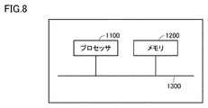
- FIG. 8 is a diagram showing an example of the hardware configuration of the image processing unit 72 and the optical axis adjustment unit 73.
- the hardware of the image processing unit 72 and the optical axis adjusting unit 73 includes a processor 1100 and a memory 1200 connected to the processor 1100 via a bus 1300.
- the image processing unit 72 and the optical axis adjusting unit 73 are realized by the processor 1100 such as a CPU (Central Processing Unit) executing a program stored in the memory 1200. Further, a plurality of processors and a plurality of memories may cooperate with each other to execute the functions of the above components.
- the processor 1100 such as a CPU (Central Processing Unit) executing a program stored in the memory 1200. Further, a plurality of processors and a plurality of memories may cooperate with each other to execute the functions of the above components.
Landscapes
- Physics & Mathematics (AREA)
- Health & Medical Sciences (AREA)
- General Health & Medical Sciences (AREA)
- General Physics & Mathematics (AREA)
- Nuclear Medicine, Radiotherapy & Molecular Imaging (AREA)
- Radiology & Medical Imaging (AREA)
- Length Measuring Devices By Optical Means (AREA)
- Length Measuring Devices With Unspecified Measuring Means (AREA)
Abstract
走査型プローブ顕微鏡は、先端部に探針(7)を有するカンチレバー(2)と、レーザ光をカンチレバーに照射し、カンチレバーで反射されたレーザ光を検出する光学系(80)と、レーザ光の光軸調整時にカンチレバー(2)の先端の位置を含む範囲を撮影するための撮影部(10)と、撮影部(10)で生成された画像から探針の先端の位置と、レーザ光のスポットの位置を検出する画像処理部(72)と、検出した位置に基づいて、レーザ光の光軸を調整する光軸調整部(73)と、試料を保持するための試料保持部(44)とを備える。試料保持部(44)は、ミラー(33)を含む。
Description
本発明は、走査型プローブ顕微鏡および走査型プローブ顕微鏡の光軸調整方法に関する。
走査型プローブ顕微鏡では、カンチレバーと呼ばれる探針が形成された片持ち梁を使用する。カンチレバーの反りまたは振動の変化を、カンチレバー背面に照射したレーザの反射光の変化に変換してフォトディテクタによって検出する。フォトディテクタでは、反射光の位置、強度、および位相等の変化を検出して、様々な物理情報に変換をする(たとえば、特許文献1(特開2000-346782号公報)を参照)。
走査型プローブ顕微鏡では、測定前には、カンチレバーの背面にレーザ光が正しく照射されるように、レーザ光の光軸調整が必要になる場合がある。その場合、カンチレバーは小さいため、調整のトレランスがミクロンオーダとなる。手動での光軸調整は難しく、煩雑な作業である。
それゆえに、本発明の目的は、光軸調整を容易に行うことができる走査型プローブ顕微鏡および走査型プローブ顕微鏡の光軸調整方法を提供することである。
本発明のある局面の走査型プローブ顕微鏡は、先端部に探針を有するカンチレバーと、測定時に、レーザ光をカンチレバーに照射し、カンチレバーで反射されたレーザ光を検出する光学系と、レーザ光の光軸調整時にカンチレバーの先端の位置を含む範囲を撮影するための撮影部と、撮影部で生成された画像から探針の先端の位置と、レーザ光のスポットの位置を検出する画像処理部と、検出した位置に基づいて、レーザ光の光軸を調整する光軸調整部と、試料を保持するための試料保持部とを備える。試料保持部は、ミラーを含む。
好ましくは、試料保持部は、ミラーの上側に載置可能な試料台を含む。
これによって、試料をミラーに直接載置することによって、ミラーが傷つくのを防止できる。
これによって、試料をミラーに直接載置することによって、ミラーが傷つくのを防止できる。
好ましくは、ミラーと前記試料台との間に間隙が形成されている。
これによって、ミラーが傷つくのをさらに防止できる。
これによって、ミラーが傷つくのをさらに防止できる。
これによって、光軸調整を容易に行うことができる。
好ましくは、試料台は、金属製であり、試料保持部は、さらに、ミラーの下に配置される磁石を有する。
好ましくは、試料台は、金属製であり、試料保持部は、さらに、ミラーの下に配置される磁石を有する。
これによって、試料台を磁石で固定することができる。
好ましくは、走査型プローブ顕微鏡は、スキャナを備える。試料保持部は、スキャナに取り付け可能なアタッチメントと、試料台によって構成される。アタッチメントの上面にミラーが形成される。アタッチメントの内部に磁石が埋設されている。
好ましくは、走査型プローブ顕微鏡は、スキャナを備える。試料保持部は、スキャナに取り付け可能なアタッチメントと、試料台によって構成される。アタッチメントの上面にミラーが形成される。アタッチメントの内部に磁石が埋設されている。
これによって、光軸調整時には、ミラーの上に試料台が置かれないようにすることができるので、ミラーによって、レーザ光を反射することができる。
好ましくは、スキャナには、円柱形状の嵌入穴が形成される。アタッチメントは、円板形状の上面と、円柱形状の突出部とを有する。突出部が、嵌入穴に嵌挿可能に構成される。
これによって、スキャナにアタッチメントを取り付けることができる。
本発明の走査型プローブ顕微鏡の光軸調整方法において、走査型プローブ顕微鏡は、先端部に探針を有するカンチレバーと、測定時に、レーザ光をカンチレバーに照射し、カンチレバーで反射されたレーザ光を検出する光学系と、試料を移動させるためのスキャナと、試料を保持するための試料保持部とを備える。試料保持部は、スキャナに取り付け可能であり、上面にミラーが形成され、内部に埋設された磁石とを含むアタッチメントと、ミラーの上に載置可能であり、金属製の試料台とを含む。光軸調整方法は、ミラーの上に試料台が載置されない状態にするステップと、光学系が、レーザ光を照射するステップと、カンチレバーの先端の位置を含む範囲を撮影するステップと、撮影によって生成された画像から探針の先端の位置と、レーザ光のスポットの位置を検出するステップと、検出した位置に基づいて、レーザ光の光軸を調整するステップとを含む。
本発明の走査型プローブ顕微鏡の光軸調整方法において、走査型プローブ顕微鏡は、先端部に探針を有するカンチレバーと、測定時に、レーザ光をカンチレバーに照射し、カンチレバーで反射されたレーザ光を検出する光学系と、試料を移動させるためのスキャナと、試料を保持するための試料保持部とを備える。試料保持部は、スキャナに取り付け可能であり、上面にミラーが形成され、内部に埋設された磁石とを含むアタッチメントと、ミラーの上に載置可能であり、金属製の試料台とを含む。光軸調整方法は、ミラーの上に試料台が載置されない状態にするステップと、光学系が、レーザ光を照射するステップと、カンチレバーの先端の位置を含む範囲を撮影するステップと、撮影によって生成された画像から探針の先端の位置と、レーザ光のスポットの位置を検出するステップと、検出した位置に基づいて、レーザ光の光軸を調整するステップとを含む。
これによって、観察対象とは異なる反射率の高い試料を配置することなく、光軸調整をすることができる。
本発明によれば、光軸調整を容易に行うことができる。
以下、実施の形態について、図面を参照して説明する。
本出願の発明は、以下を検討した。
本出願の発明は、以下を検討した。
手動での光軸調整は難しいため、光軸調整を容易にするには、光軸調整を自動化することが考えられる。
光軸自動調整では、例えば、カンチレバーとレーザ光のビームのスポットを光学顕微鏡またはCCD(Charge Coupled Device)などの撮影部で観察し、ビームのスポットがカンチレバーの背面に照射される様に、光学部品、レーザ光源、または、カンチレバーを自動で移動させることが考えられる。
しかしながら、光軸自動調整では、カンチレバーの下方に配置した試料の表面の反射率が低いと、撮影部に入射されるレーザの反射光量が少ないため、撮影部では、レーザスポットの位置を適切に検出することができない。そのため、光軸調整の際に、観察対象とは異なる反射率の高い試料またはミラーを配置する必要がある。光軸調整の際に、観察対象とは異なる反射率の高い試料またはミラーを配置する動作は手間がかかり、測定前の作業を煩雑にする。それゆえ、本出願の発明者は、光軸調整の際に、観察対象とは異なる反射率の高い試料またはミラーを配置することなく、光軸自動調整が可能な構成および方法について検討した。
図1は、実施形態の走査型プローブ顕微鏡1の構成を表わす図である。
実施形態の走査型プローブ顕微鏡1は、撮影部10と、画像処理部72と、光軸調整部73と、光学系80と、カンチレバー2と、測定部14と、駆動機構49と、スキャナ43と、試料保持部44と、駆動機構11とを備える。
実施形態の走査型プローブ顕微鏡1は、撮影部10と、画像処理部72と、光軸調整部73と、光学系80と、カンチレバー2と、測定部14と、駆動機構49と、スキャナ43と、試料保持部44と、駆動機構11とを備える。
カンチレバー2は、表面の自由端部である先端に探針7を有する。試料Sは、探針7に対向して配置されている。探針7と試料Sとの間の原子間力(引力または斥力)によって、カンチレバー2が変位する。試料Sは、試料保持部44上に載置される。
光学系80は、測定時に、レーザ光をカンチレバー2の裏面に照射し、カンチレバー2の裏面で反射されたレーザ光を検出する。光学系80は、カンチレバー2のたわみを検出することができる。光学系80は、レーザ光源60と、第1のミラーであるビームスプリッタ3と、第2のミラーである反射鏡4と、光検出器5とを備える。レーザ光源60は、レーザ光を発射するレーザ発振器などによって構成される。光検出器5は、入射されるレーザ光を検出するフォトダイオードなどによって構成される。レーザ光源60から発射されたレーザ光は、ビームスプリッタ3で反射されて、カンチレバー2に入射される。レーザ光は、カンチレバー2で反射され、さらに反射鏡4によって反射されて、光検出器5に入射される。光検出器5がレーザ光を検出することによって、カンチレバー2の変位を測定することができる。
駆動機構11は、レーザ光源60の位置を変化させることによって、レーザ光の光軸を調整する。
測定部14は、光学系80で検出されるレーザ光の位置の変化によって得られるカンチレバー2の変位に基づいて、試料Sの特性を測定する。たとえば、測定部14は、カンチレバー2の変位の時間変化から作用力(フォース)の時間変化を表わすフォースカーブなどを作成する。測定部14は、スキャナ43を駆動するための制御信号を駆動機構49へ送る。
駆動機構49は、スキャナ43を駆動することによって、スキャナ43に載置された試料Sと探針7との間の相対的な位置関係を変化させる。
撮影部10は、レーザ光の光軸調整時に探針7の位置を含む範囲を撮影する。撮影部10は、光学顕微鏡、CCDカメラ、CMOS(Complementary Metal Oxide Semiconductor)カメラなどによって構成される。
スキャナ43は、駆動機構49によって3次元方向に駆動される。スキャナ43は、外部から印加される電圧によって変形するピエゾ素子によって構成される。
試料保持部44は、試料Sを載置する。試料保持部44は、スキャナ43に取り付け可能に構成される。
画像処理部72は、撮影部10から出力される撮影画像に基づいて、レーザ光のスポットSPの位置およびカンチレバー2の先端TPの位置を特定する。
光軸調整部73は、画像処理部72によって特定されたレーザ光のスポットSPの位置とカンチレバーの先端の位置とに基づいて、駆動機構11を制御することによって、レーザ光源60の位置を変化させることによって、光軸を調整する。
図2は、探針7、カンチレバー2およびホルダ15を表わす図である。図2に示すように、探針7は、カンチレバー2の先端に取り付けられる。ホルダ15は、カンチレバー2を支持する部材である。
図3は、走査型プローブ顕微鏡1において試料観察を行う際のスキャナ43の上部および試料保持部44の縦断面図である。図4は、試料保持部44に含まれるスタブ型アタッチメント30をスキャナ43に装着する前の状態を表わす図である。図5は、走査型プローブ顕微鏡1において光軸調整を行う際のスキャナ43の上部の縦断面図である。
スキャナ43のピエゾチューブ511の上端面には、中央に円柱形状の嵌入穴23を有する略ドーナツ形状の台座部22が固着されている。台座部22の周面には水平方向に固定ネジ24が螺入されており、その固定ネジ24を横方向から回すことができるように、スキャナハウジング510には切欠き101が形成されている。
試料保持部44は、スタブ型アタッチメント30と、試料台52とを含む。
スタブ型アタッチメント30は下方に凸部31が形成されるとともに、上面には円盤状のミラー33が形成されている。スタブ型アタッチメント30は、内側には磁石32が埋設されている。スタブ型アタッチメント30は、アルミ製である。
スタブ型アタッチメント30は下方に凸部31が形成されるとともに、上面には円盤状のミラー33が形成されている。スタブ型アタッチメント30は、内側には磁石32が埋設されている。スタブ型アタッチメント30は、アルミ製である。
台座部22の嵌入穴23にスタブ型アタッチメント30の凸部31が嵌挿される。固定ネジ24を締め付けることによって、スタブ型アタッチメント30を台座部22に固定できる。
試料台52には、試料Sを載せることができる。試料台52は、金属製であり、円板状である。
試料の観察時には、ミラー33の上側に試料台52が載置される。スタブ型アタッチメント30内の磁石32の吸引力によって、試料台52を固定することができる。ミラー33と試料台52の間には、隙間38が形成されている。これによって、試料台52によってミラー33に傷がつくのを防止できる。
光軸調整時には、ミラー33の上に試料台52が載置されない。レーザ光が試料台52によって遮らずに、ミラー33に入射されて、反射されたレーザ光が試料台52によって遮らずに、撮影部10に入射される。
図6は、撮影画像IMGの例を表わす図である。
撮影画像IMGには、カンチレバー2の先端TPと、レーザ光のビームのスポットSPが含まれる。レーザ光のビームのスポットSPの中心O1の画素の位置(x1,y1)とカンチレバー2の先端TPの中心O2の画素の位置(x2,y2)とから、レーザ光のビームのスポットSPの中心O1が、カンチレバー2の先端TPの中心O2と一致するために、レーザ光源60の移動方向および移動量を特定することができる。
撮影画像IMGには、カンチレバー2の先端TPと、レーザ光のビームのスポットSPが含まれる。レーザ光のビームのスポットSPの中心O1の画素の位置(x1,y1)とカンチレバー2の先端TPの中心O2の画素の位置(x2,y2)とから、レーザ光のビームのスポットSPの中心O1が、カンチレバー2の先端TPの中心O2と一致するために、レーザ光源60の移動方向および移動量を特定することができる。
図7は、実施形態のレーザ光の光軸調整手順を表わすフローチャートである。この光軸調整は、たとえば、カンチレバー2の交換時、および試料Sの物性の測定前に実施される。
ステップS101において、スタブ型アタッチメント30のミラー33の上に試料台52が載置されていない状態にする。
ステップS102において、レーザ光源60は、レーザ光を放射する。
ステップS103において、撮影部10がカンチレバー2の先端の含む範囲を撮影する。
ステップS103において、撮影部10がカンチレバー2の先端の含む範囲を撮影する。
ステップS104において、画像処理部72は、撮影部10から出力される撮影画像におけるレーザ光のスポットSPの中心O1の画素の位置(x1,y1)と、カンチレバー2の先端TPの中心O2の画素の位置(x2,y2)とを特定する。
ステップS105において、光軸調整部73は、(x1,y1)と(x2,y2)とに基づいて、レーザ光のスポットSPの中心O1の位置が、探針7が取り付けられているカンチレバー2の先端の中心O2の位置と一致するように、レーザ光源60を移動させるために駆動機構11を制御する制御信号を出力する。駆動機構11は、制御信号に従って、レーザ光源60の位置を変化させることによって、レーザ光の光軸を調整する。
以上のように、本実施の形態によれば、レーザ光の光軸調整時に、試料台52が取り除かれることによって、レーザ光をミラー33に入射させて、反射させる。これによって、撮影部で、レーザスポットを検出することができるため、レーザ光の光軸調整時に、観察対象とは異なる反射率の高い試料またはミラーを配置する手間を省くことができる。本実施の形態では、試料は、直接ミラーの上に載置されないので、ミラーを傷つけることを防止できる。試料台とミラーの間に隙間が形成されているので、ミラーが傷つくのをさらに防止できる。
(変形例)
本発明は、上記の実施形態に限定されるものではなく、たとえば、以下のような変形例も含む。
本発明は、上記の実施形態に限定されるものではなく、たとえば、以下のような変形例も含む。
(1)試料台
上記の実施形態では、試料保持部が試料台を含み、試料台に試料を載置されるものとしたが、これに限定されるものではない。ミラーに傷がつかないように、ミラー面にコーティングを施すことによって、ミラー面に直接試料を載置するものとしてもよい。
上記の実施形態では、試料保持部が試料台を含み、試料台に試料を載置されるものとしたが、これに限定されるものではない。ミラーに傷がつかないように、ミラー面にコーティングを施すことによって、ミラー面に直接試料を載置するものとしてもよい。
(2)隙間
上記の実施形態では、ミラーと試料台の間に隙間が形成されるものとしたが、これに限定されるものではない。ミラーの上に直接試料台が載置されるものとしてもよい。
上記の実施形態では、ミラーと試料台の間に隙間が形成されるものとしたが、これに限定されるものではない。ミラーの上に直接試料台が載置されるものとしてもよい。
(3)光軸調整載置
レーザ光の光軸を調整するために、駆動機構11が、レーザ光源60の位置を変化させたが、これに限定されるものではない。別の駆動機構が、カンチレバー2を支持するホルダ15の位置を変化させることによって、レーザ光の光軸を調整することとしてもよい。あるいは、別の駆動機構が、ビームスプリッタ3の位置を変化させることによって、レーザ光の光軸を調整することとしてもよい。
レーザ光の光軸を調整するために、駆動機構11が、レーザ光源60の位置を変化させたが、これに限定されるものではない。別の駆動機構が、カンチレバー2を支持するホルダ15の位置を変化させることによって、レーザ光の光軸を調整することとしてもよい。あるいは、別の駆動機構が、ビームスプリッタ3の位置を変化させることによって、レーザ光の光軸を調整することとしてもよい。
(4) 画像処理部および光軸調整部
図8は、画像処理部72および光軸調整部73のハードウエア構成の例を表わす図である。画像処理部72および光軸調整部73のハードウエアは、プロセッサ1100と、プロセッサ1100とバス1300で接続されたメモリ1200とを備える。
図8は、画像処理部72および光軸調整部73のハードウエア構成の例を表わす図である。画像処理部72および光軸調整部73のハードウエアは、プロセッサ1100と、プロセッサ1100とバス1300で接続されたメモリ1200とを備える。
CPU(Central Processing Unit)などのプロセッサ1100がメモリ1200に記憶されたプログラムを実行することにより、画像処理部72および光軸調整部73が実現される。また、複数のプロセッサおよび複数のメモリが連携して上記構成要素の機能を実行するものとしてもよい。
今回開示された実施の形態はすべての点で例示であって制限的なものではないと考えられるべきである。本発明の範囲は上記した説明ではなくて請求の範囲によって示され、請求の範囲と均等の意味および範囲内でのすべての変更が含まれることが意図される。
1 走査型プローブ顕微鏡、2 カンチレバー、3 ビームスプリッタ、4 反射鏡、5 光検出器、7 探針、10 撮影部、11,49 駆動機構、14 測定部、15 ホルダ、 22 台座部、23 嵌入穴、24 固定ネジ、30 スタブ型アタッチメント、31 凸部、32 マグネット、33 ミラー、38 隙間、43 スキャナ、44 試料保持部、52 試料台、60 レーザ光源、72 画像処理部、73 光軸調整部、80 光学系、101 切欠き、510 スキャナハウジング、511 ピエゾチューブ、1100 プロセッサ、1200 メモリ、S 試料。
Claims (7)
- 先端部に探針を有するカンチレバーと、
測定時に、レーザ光を前記カンチレバーに照射し、前記カンチレバーで反射されたレーザ光を検出する光学系と、
前記レーザ光の光軸調整時に前記カンチレバーの先端の位置を含む範囲を撮影するための撮影部と、
前記撮影部で生成された画像から前記探針の先端の位置と、前記レーザ光のスポットの位置を検出する画像処理部と、
前記検出した位置に基づいて、前記レーザ光の光軸を調整する光軸調整部と、
試料を保持するための試料保持部とを備え、
前記試料保持部は、
ミラーを含む、走査型プローブ顕微鏡。 - 前記試料保持部は、前記ミラーの上側に載置可能な試料台を含む、請求項1記載の走査型プローブ顕微鏡。
- 前記ミラーと前記試料台との間に隙間が形成されている、請求項2記載の走査型プローブ顕微鏡。
- 前記試料台は、金属製であり、
前記試料保持部は、さらに、
前記ミラーの下に配置される磁石を有する、請求項2記載の走査型プローブ顕微鏡。 - スキャナを備え、
前記試料保持部は、前記スキャナに取り付け可能なアタッチメントと、前記試料台によって構成され、
前記アタッチメントの上面に前記ミラーが形成され、前記アタッチメントの内部に磁石が埋設されている、請求項2記載の走査型プローブ顕微鏡。 - 前記スキャナには、円柱形状の嵌入穴が形成され、
前記アタッチメントは、円板形状の上面と、円柱形状の突出部とを有し、
前記突出部が、前記嵌入穴に嵌挿可能に構成される、請求項5記載の走査型プローブ顕微鏡。 - 走査型プローブ顕微鏡の光軸調整方法であって、
前記走査型プローブ顕微鏡は、
先端部に探針を有するカンチレバーと、
測定時に、レーザ光を前記カンチレバーに照射し、前記カンチレバーで反射された前記レーザ光を検出する光学系と、
試料を移動させるためのスキャナと、
試料を保持するための試料保持部とを備え、
前記試料保持部は、
前記スキャナに取り付け可能であり、上面にミラーが形成され、内部に埋設された磁石とを含むアタッチメントと、
前記ミラーの上に載置可能であり、金属製の試料台とを含み、
前記ミラーの上に前記試料台が載置されない状態にするステップと、
前記光学系が、前記レーザ光を照射するステップと、
前記カンチレバーの先端の位置を含む範囲を撮影するステップと、
前記撮影によって生成された画像から前記探針の先端の位置と、前記レーザ光のスポットの位置を検出するステップと、
前記検出した位置に基づいて、前記レーザ光の光軸を調整するステップとを含む、走査型プローブ顕微鏡の光軸調整方法。
Priority Applications (2)
| Application Number | Priority Date | Filing Date | Title |
|---|---|---|---|
| US17/294,998 US11519936B2 (en) | 2018-11-20 | 2019-07-03 | Scanning probe microscope and scanning probe microscope optical axis adjustment method |
| CN201980070728.2A CN112955753B (zh) | 2018-11-20 | 2019-07-03 | 扫描型探针显微镜的光轴调整方法 |
Applications Claiming Priority (2)
| Application Number | Priority Date | Filing Date | Title |
|---|---|---|---|
| JP2018-217360 | 2018-11-20 | ||
| JP2018217360A JP6627953B1 (ja) | 2018-11-20 | 2018-11-20 | 走査型プローブ顕微鏡の光軸調整方法 |
Publications (1)
| Publication Number | Publication Date |
|---|---|
| WO2020105213A1 true WO2020105213A1 (ja) | 2020-05-28 |
Family
ID=69101107
Family Applications (1)
| Application Number | Title | Priority Date | Filing Date |
|---|---|---|---|
| PCT/JP2019/026489 Ceased WO2020105213A1 (ja) | 2018-11-20 | 2019-07-03 | 走査型プローブ顕微鏡および走査型プローブ顕微鏡の光軸調整方法 |
Country Status (4)
| Country | Link |
|---|---|
| US (1) | US11519936B2 (ja) |
| JP (1) | JP6627953B1 (ja) |
| CN (1) | CN112955753B (ja) |
| WO (1) | WO2020105213A1 (ja) |
Families Citing this family (3)
| Publication number | Priority date | Publication date | Assignee | Title |
|---|---|---|---|---|
| JP7665291B2 (ja) | 2020-03-30 | 2025-04-21 | 株式会社島津製作所 | 走査型プローブ顕微鏡および走査型プローブ顕微鏡における光軸調整方法 |
| JP7635630B2 (ja) * | 2021-05-07 | 2025-02-26 | 株式会社島津製作所 | 分析装置、表示制御方法、表示制御プログラム |
| US20230204624A1 (en) * | 2021-12-24 | 2023-06-29 | Park Systems Corp. | Apparatus and method for identifying target position in atomic force microscope |
Citations (5)
| Publication number | Priority date | Publication date | Assignee | Title |
|---|---|---|---|---|
| JPH08220109A (ja) * | 1995-02-16 | 1996-08-30 | Hitachi Constr Mach Co Ltd | プローブ顕微鏡の探針先端位置特定方法 |
| JP2007003246A (ja) * | 2005-06-22 | 2007-01-11 | Jeol Ltd | 走査形プローブ顕微鏡 |
| JP2011521202A (ja) * | 2008-06-27 | 2011-07-21 | 日本電信電話株式会社 | 走査型プローブ顕微鏡用ステージ及び試料観察方法 |
| JP2016183869A (ja) * | 2015-03-25 | 2016-10-20 | 株式会社日立ハイテクサイエンス | 走査プローブ顕微鏡 |
| JP2017049087A (ja) * | 2015-09-01 | 2017-03-09 | 株式会社日立ハイテクサイエンス | 走査プローブ顕微鏡および走査プローブ顕微鏡の光軸調整方法 |
Family Cites Families (7)
| Publication number | Priority date | Publication date | Assignee | Title |
|---|---|---|---|---|
| JP2852196B2 (ja) * | 1995-02-16 | 1999-01-27 | 防衛庁技術研究本部長 | 水中音響信号方位計算装置 |
| JP4489869B2 (ja) | 1999-06-04 | 2010-06-23 | 株式会社島津製作所 | 走査型プローブ顕微鏡 |
| JP5033609B2 (ja) * | 2007-03-12 | 2012-09-26 | 株式会社日立製作所 | 走査プローブ顕微鏡およびこれを用いた試料の観察方法 |
| US7962966B2 (en) * | 2009-05-26 | 2011-06-14 | Agilent Technologies, Inc. | Scanning probe microscope having improved optical access |
| JP5527274B2 (ja) * | 2011-04-19 | 2014-06-18 | 株式会社島津製作所 | 走査型プローブ顕微鏡 |
| JP2017101923A (ja) * | 2014-03-05 | 2017-06-08 | 株式会社日立製作所 | 走査プローブ顕微鏡及び、これを用いた試料測定方法 |
| CN104634997B (zh) * | 2015-02-27 | 2017-09-19 | 天津大学 | 一种适用于高速扫描的原子力显微镜系统 |
-
2018
- 2018-11-20 JP JP2018217360A patent/JP6627953B1/ja active Active
-
2019
- 2019-07-03 WO PCT/JP2019/026489 patent/WO2020105213A1/ja not_active Ceased
- 2019-07-03 CN CN201980070728.2A patent/CN112955753B/zh active Active
- 2019-07-03 US US17/294,998 patent/US11519936B2/en active Active
Patent Citations (5)
| Publication number | Priority date | Publication date | Assignee | Title |
|---|---|---|---|---|
| JPH08220109A (ja) * | 1995-02-16 | 1996-08-30 | Hitachi Constr Mach Co Ltd | プローブ顕微鏡の探針先端位置特定方法 |
| JP2007003246A (ja) * | 2005-06-22 | 2007-01-11 | Jeol Ltd | 走査形プローブ顕微鏡 |
| JP2011521202A (ja) * | 2008-06-27 | 2011-07-21 | 日本電信電話株式会社 | 走査型プローブ顕微鏡用ステージ及び試料観察方法 |
| JP2016183869A (ja) * | 2015-03-25 | 2016-10-20 | 株式会社日立ハイテクサイエンス | 走査プローブ顕微鏡 |
| JP2017049087A (ja) * | 2015-09-01 | 2017-03-09 | 株式会社日立ハイテクサイエンス | 走査プローブ顕微鏡および走査プローブ顕微鏡の光軸調整方法 |
Also Published As
| Publication number | Publication date |
|---|---|
| CN112955753B (zh) | 2024-06-14 |
| CN112955753A (zh) | 2021-06-11 |
| JP2020085562A (ja) | 2020-06-04 |
| JP6627953B1 (ja) | 2020-01-08 |
| US20220018873A1 (en) | 2022-01-20 |
| US11519936B2 (en) | 2022-12-06 |
Similar Documents
| Publication | Publication Date | Title |
|---|---|---|
| US10684456B2 (en) | Microscope | |
| JP5897563B2 (ja) | ライン走査式顕微鏡における同期用システム | |
| JP2017049087A5 (ja) | ||
| JP5189321B2 (ja) | 固浸レンズホルダ | |
| JP6588278B2 (ja) | 走査プローブ顕微鏡および走査プローブ顕微鏡の光軸調整方法 | |
| JP6627953B1 (ja) | 走査型プローブ顕微鏡の光軸調整方法 | |
| KR20210025130A (ko) | 다수의 파장을 사용하는 다수의 작업 거리 높이 센서 | |
| JP2018151187A (ja) | 走査型プローブ顕微鏡 | |
| JP6954474B2 (ja) | 走査型プローブ顕微鏡および走査型プローブ顕微鏡の制御装置 | |
| JP2012227701A (ja) | 画像評価用のチャート、カメラモジュールのピントずれ方向・量測定装置、カメラモジュールのレンズ位置調整装置、カメラモジュールのピント調整装置、カメラモジュール搭載用のパレット、カメラモジュール用接着剤塗付装置 | |
| JP4890039B2 (ja) | 共焦点型撮像装置 | |
| JP5226352B2 (ja) | 生体観察装置及び生体観察方法 | |
| JP3780028B2 (ja) | 走査型プローブ顕微鏡用の調整治具 | |
| US20120262807A1 (en) | Lens barrel and image capturing apparatus | |
| JP4567458B2 (ja) | 共焦点顕微鏡を用いてシリンダ内壁の表面を測定するための装置 | |
| JP4391806B2 (ja) | 光学顕微鏡 | |
| KR20190063027A (ko) | 라인 스캐닝 방식의 공초점 현미경에서의 자동초점조절 방법 및 장치 | |
| JP5019507B2 (ja) | レーザ加工装置および加工対象物の位置検出方法 | |
| JP2008134190A (ja) | カンチレバーホルダーおよびこれを備えた走査型プローブ顕微鏡 | |
| JP2001004329A (ja) | 測定器および共焦点顕微鏡 | |
| JP7742554B2 (ja) | 照明付撮像装置および位置調整装置 | |
| JP2007259166A (ja) | 撮像素子のアオリ調整方法及び該方法で調整された撮像素子を有するカメラ機器 | |
| JP4076374B2 (ja) | 走査型プローブ装置 | |
| JP2008122629A (ja) | 3次元顕微鏡システム | |
| JP2019035837A (ja) | 顕微鏡システム、顕微鏡システムの制御方法 |
Legal Events
| Date | Code | Title | Description |
|---|---|---|---|
| 121 | Ep: the epo has been informed by wipo that ep was designated in this application |
Ref document number: 19887141 Country of ref document: EP Kind code of ref document: A1 |
|
| NENP | Non-entry into the national phase |
Ref country code: DE |
|
| 122 | Ep: pct application non-entry in european phase |
Ref document number: 19887141 Country of ref document: EP Kind code of ref document: A1 |