WO2020101018A1 - ステアリングコラム装置 - Google Patents
ステアリングコラム装置 Download PDFInfo
- Publication number
- WO2020101018A1 WO2020101018A1 PCT/JP2019/044900 JP2019044900W WO2020101018A1 WO 2020101018 A1 WO2020101018 A1 WO 2020101018A1 JP 2019044900 W JP2019044900 W JP 2019044900W WO 2020101018 A1 WO2020101018 A1 WO 2020101018A1
- Authority
- WO
- WIPO (PCT)
- Prior art keywords
- hole
- column
- pair
- bracket
- portions
- Prior art date
- Legal status (The legal status is an assumption and is not a legal conclusion. Google has not performed a legal analysis and makes no representation as to the accuracy of the status listed.)
- Ceased
Links
Images







Classifications
-
- B—PERFORMING OPERATIONS; TRANSPORTING
- B62—LAND VEHICLES FOR TRAVELLING OTHERWISE THAN ON RAILS
- B62D—MOTOR VEHICLES; TRAILERS
- B62D1/00—Steering controls, i.e. means for initiating a change of direction of the vehicle
- B62D1/02—Steering controls, i.e. means for initiating a change of direction of the vehicle vehicle-mounted
- B62D1/16—Steering columns
- B62D1/18—Steering columns yieldable or adjustable, e.g. tiltable
- B62D1/19—Steering columns yieldable or adjustable, e.g. tiltable incorporating energy-absorbing arrangements, e.g. by being yieldable or collapsible
- B62D1/192—Yieldable or collapsible columns
-
- B—PERFORMING OPERATIONS; TRANSPORTING
- B62—LAND VEHICLES FOR TRAVELLING OTHERWISE THAN ON RAILS
- B62D—MOTOR VEHICLES; TRAILERS
- B62D1/00—Steering controls, i.e. means for initiating a change of direction of the vehicle
- B62D1/02—Steering controls, i.e. means for initiating a change of direction of the vehicle vehicle-mounted
- B62D1/16—Steering columns
- B62D1/18—Steering columns yieldable or adjustable, e.g. tiltable
- B62D1/184—Mechanisms for locking columns at selected positions
-
- B—PERFORMING OPERATIONS; TRANSPORTING
- B62—LAND VEHICLES FOR TRAVELLING OTHERWISE THAN ON RAILS
- B62D—MOTOR VEHICLES; TRAILERS
- B62D1/00—Steering controls, i.e. means for initiating a change of direction of the vehicle
- B62D1/02—Steering controls, i.e. means for initiating a change of direction of the vehicle vehicle-mounted
- B62D1/16—Steering columns
- B62D1/18—Steering columns yieldable or adjustable, e.g. tiltable
- B62D1/185—Steering columns yieldable or adjustable, e.g. tiltable adjustable by axial displacement, e.g. telescopically
Definitions
- the present invention relates to a steering column device for rotatably supporting a steering shaft that supports a steering wheel.
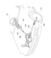
- FIG. 16 shows an example of a steering device for an automobile.
- the rotation of the steering wheel 101 is transmitted to the steering gear unit 105 via the steering shaft 102, the universal joint 103, the intermediate shaft 104, etc., and is converted into a linear motion by the steering gear unit 105.
- This linear movement pushes and pulls the left and right tie rods 106 to give a steered wheel 107 a steering angle.
- the steering shaft 102 is rotatably supported by the steering column device 108 with respect to the vehicle body.
- the steering column device 108a includes a tilt mechanism for adjusting the position of the steering wheel, a telescopic mechanism, and a shock absorbing mechanism for reducing a shock load applied to the driver's body in the event of a secondary collision. .. Among them, in order to configure the telescopic mechanism, the steering column 109 is fitted to the rear portion of the front outer column 110 and the front portion of the rear inner column 111 so as to allow relative displacement in the axial direction. Due to this, the entire length can be expanded and contracted.
- the outer column 110 has a slit 112 extending in the axial direction on the lower surface of the rear side portion, and a pair of sandwiched portions 113 at positions sandwiching the slit 112 from both sides in the width direction.
- the inner column 111 supports and fixes the engaged member 114 to a portion of the lower surface that is inside the slit 112.
- a cam member 116 is externally fitted and fixed to an axially intermediate portion of an adjusting rod 115 arranged so as to penetrate the pair of sandwiched portions 113 in the width direction.
- the adjustment lever 117 is swung to expand the axial dimension of the cam device 118, so that the pair of support plate portions 120 forming the vehicle body side bracket 119 can be used to The pair of sandwiched portions 113 are strongly suppressed from both sides in the width direction.
- the engagement member 121 is pivotally displaced about the support shaft 122 whose ends on both axial sides are supported by the pair of clamped portions 113, whereby the engagement member 121 is swung.
- the engaging protrusion 123 of 121 is engaged with the recess of the engaged member 114 supported and fixed to the inner column 111. This prevents axial displacement of the inner column 111 with respect to the outer column 110.
- the support shaft 122 has a planned rupture portion that ruptures based on the forward-directed impact load applied to the inner column 111 during a secondary collision. That is, at the time of the secondary collision, when the expected breakage portion breaks due to the forward impact load being applied to the inner column 111, the inner column 111 separates forward and the steering wheel 101 is displaced forward. Is acceptable.
- the steering column device 108a further includes a rotation stop mechanism for preventing relative rotation between the outer column 110 and the inner column 111.
- a rotation stop mechanism for preventing relative rotation between the outer column 110 and the inner column 111.
- a groove 124 that extends in the axial direction is formed in the upper end of the inner peripheral surface of the outer column 110, and the upper surface of the inner column 111 is formed in the groove 124.
- the detent member 125 which is supported and fixed to, is engaged.
- a slit 112 that extends in the axial direction is formed on the lower surface of the outer column 110, and an axial direction is formed at the upper end of the inner peripheral surface of the outer column 110.
- a recessed groove 124 that extends in the direction of is formed. Therefore, in order to secure the length of the concave groove 124, it is necessary to lengthen the slit 112 for processing, which is also disadvantageous in terms of securing the strength of the outer column 110.
- the present invention has an object to realize a structure of a steering column device that improves the workability of the outer column and easily secures the strength.
- the steering column device of the present invention includes an inner column, an outer column, a vehicle body side bracket, an adjusting rod, a pair of pressing portions, a scaling device, a telescopic friction plate, a release bracket, and a support bracket. ..
- the outer column includes a rear portion into which a front portion of the inner column is fitted, a slit extending in the axial direction, a pair of sandwiched portions arranged at positions sandwiching the slit from both sides in the width direction, There is a pair of column-side through holes that penetrate each of the pair of clamped portions in the width direction.
- the vehicle body side bracket includes a pair of support plate portions that sandwich the pair of sandwiched portions, and a pair of vehicle body side through holes formed in portions of the pair of support plate portions that are aligned with each other. ..
- the adjusting rod is inserted through the pair of column side through holes and the pair of vehicle body side through holes.
- the pair of pressing portions are arranged at portions of the adjusting rod that project from the outer surfaces of the pair of support plate portions.
- the expansion / contraction device expands / contracts a space between the pair of pressing portions.
- the telescopic friction plate has a portion between an inner surface of the pair of support plate portions and an outer surface of the pair of clamped portions, and an outer surface of the pair of support plate portions and the pair of pressing members.
- the detachment bracket is arranged inside the slit and is supported and fixed to the inner column.
- the support bracket includes a mounting portion that is separably coupled to the disengagement bracket based on an impact load applied to the inner column at the time of a secondary collision, and a support arm portion that supports the telescopic friction plate. ..
- a leaf spring portion that is elastically deformable in the width direction is sandwiched by at least one of the portions between the inner side surfaces of the slits in the width direction and the outer side surfaces of the detachable bracket in the width direction. It is preferable to provide.
- the leaf spring portion can be formed by a part of a current-carrying plate that electrically connects the inner column and the outer column.
- the height from the shaft is preferably about the same, and most preferably the same.
- the inner column includes an engagement hole and a mounting hole that is spaced apart from the engagement hole in the front-rear direction
- the detachment bracket includes a first fixed-side through hole and the first fixed-side through hole.
- a second fixed-side through hole that is spaced apart in the front-rear direction, and a third fixed-side through hole that is arranged on the opposite side of the first fixed-side through hole with the second fixed-side through hole interposed therebetween.
- a cylindrical engaging projection protruding inward in the radial direction of the inner column is provided so as to surround the second fixed-side through hole, and the mounting portion of the support bracket is the first disengagement portion.
- a side through hole and a second separate side through hole that is arranged to be separated from the first separate side through hole in the front-rear direction.
- a fixing member such as a screw or a bolt and a nut
- the support bracket By inserting (press-fitting) the coupling member over the inner side of the support bracket, the support bracket is inserted into the release bracket based on the impact load applied to the inner column at the time of a secondary collision.
- the coupling member is sheared so as to be separably coupled.
- the steering column device of the present invention improves the workability of the outer column and easily secures its strength as compared with the structure described in JP-A-2016-165935.
- FIG. 1 is a perspective view showing an example of a steering column device according to an embodiment of the present invention.
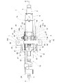
- FIG. 2 is a plan view showing a state in which the front and rear positions of the steering wheel are moved to an intermediate position within the adjustable range in the steering column device of FIG.
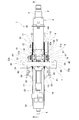
- FIG. 3 is a sectional view taken along the line AA of FIG.
- FIG. 4 is a plan view showing the steering column device of FIG. 1 in which the front-rear position of the steering wheel is moved to the rear end position of the adjustable range.
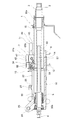
- FIG. 5 is a sectional view taken along line BB of FIG.
- FIG. 6 is a view similar to FIG. 3, showing a state in which the front-rear position of the steering wheel is moved to the front end position of the adjustable range in the steering column device of FIG. 1.
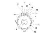
- FIG. 7 is an enlarged view of part C of FIG.
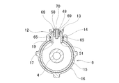
- FIG. 8 is a sectional view taken along line DD of FIG.
- FIG. 9 is a sectional view taken along line EE of FIG.
- FIG. 10 is a sectional view taken along line FF in FIG.
- FIG. 11 is a sectional view taken along line GG of FIG.
- FIG. 12 is a view similar to FIG. 3 showing a state after the secondary collision occurs in the steering column device of FIG. 1.
- FIG. 13 is an enlarged view of part H of FIG.
- FIG. 14 is an exploded perspective view showing the steering column device of FIG. 1.
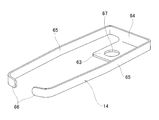
- FIG. 15 is a perspective view showing an energization plate taken out from the steering column device of FIG.
- FIG. 16 is a perspective view showing an example of a conventional structure of a steering device.
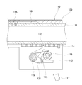
- FIG. 17 is a sectional view showing an example of a conventional structure of a steering column device.
- FIG. 18 is a view showing the II cross section of FIG. 17
- the steering column device 1 of this example is for supporting a steering shaft 2 having a steering wheel 101 (see FIG. 16) supported at a rear end thereof rotatably with respect to a vehicle body.
- the vertical direction, the front-rear direction, and the width direction are the vertical direction, the front-rear direction, and the width direction when the steering column device 1 is assembled to a vehicle, unless otherwise specified.
- the steering shaft 2 has a structure in which the upper shaft 3 and the lower shaft 4 are combined by spline engagement or the like so that torque can be transmitted and the entire length can be expanded and contracted.
- the steering wheel 101 is supported and fixed to the rear end of the upper shaft 3.
- the key lock collar 5 that constitutes the steering lock device is externally fitted and fixed to the axially intermediate portion of the upper shaft 3.
- the steering column device 1 includes a steering column 6, a vehicle body side bracket 7, an adjusting rod 8, an adjusting lever 9 and a cam device 10 which form an expansion / contraction device, a telescopic friction plate 11, a disengagement bracket 12, and a support bracket 13. And an energizing plate 14.
- the steering column 6 is configured so that its entire length can be expanded and contracted by fitting the front portion of the rear inner column 15 and the rear portion of the front outer column 16 so as to be capable of relative displacement in the axial direction.
- the inner column 15 is formed in a tubular shape, and as shown in FIG. 7, an engagement hole 17 having a substantially rectangular opening shape is provided on the upper surface of the front portion, and the inner column 15 has an engagement hole of the upper surface of the front portion.
- a mounting hole 18 having a female screw portion on the inner peripheral surface (which is a screw hole) is provided at a portion located on the rear side of the hole 17.
- the inner column 15 of this example has a coating layer made of synthetic resin on the outer peripheral surface. Such a coating layer has a function of suppressing sliding resistance to the outer column 16 to be low.
- the outer column 16 is formed in a tubular shape, and has a slit 19, a pair of clamped portions 20a and 20b, and a pair of column-side through holes (not shown).
- the slit 19 has a function of expanding and contracting the inner diameter of the rear portion of the outer column 16, and is formed on the upper surface from the middle portion to the rear portion of the outer column 16 so as to extend in the axial direction.
- the slit 19 of this example has a substantially T-shaped opening shape when viewed in the radial direction.
- the slit 19 of the present example has a main slit portion 22 formed so as to radially pass through and extend in the axial direction on the upper surface from the middle portion to the rear portion of the outer column 16 and the outer column 16.
- the sub-slit portion 23 is formed in the rear side portion so as to pass through in the radial direction and extend in the circumferential direction, and the rear side end portion of the main slit portion 22 is opened in the circumferential intermediate portion. ..
- the rear end portion of the slit 19 is not opened to the rear end surface of the outer column 16, but it may be opened.
- the pair of sandwiched portions 20a and 20b are arranged at positions sandwiching the rear portion of the slit 19 from both sides in the width direction.
- Each of the pair of column-side through holes is a mere circular hole, and is located at a portion of the pair of sandwiched portions 20a, 20b that are aligned with each other (that is, so as to be coaxial with the pair of sandwiched portions 20a, 20b). In addition, it is formed so as to penetrate each of the pair of sandwiched portions 20a and 20b in the width direction.
- the outer column 16 has a swing support bracket portion 24 that extends forward and upward at a portion existing on the front side of the slit 19 at the front end portion.
- the swing support bracket portion 24 has a swing support hole 25 penetrating in the width direction of the vehicle body and having a circular cross-sectional shape (a circular hole).
- the outer column 16 is supported by the vehicle body so as to be capable of swinging about the tilt axis by inserting a tilt shaft whose end portion is supported by the vehicle body into the swing support hole 25.
- the outer column 16 further has a pair of protrusions 26 protruding upward at positions sandwiching the front portion of the slit 19 from both sides in the width direction.
- the stopper member 27 is attached so as to span the pair of projecting piece portions 26.
- the stopper member 27 is made of a polymer material such as synthetic resin or rubber, and has recesses 28 recessed upward on the lower surfaces of the ends on both sides in the width direction.
- the outer column 16 further has a lock through hole 29 in the front portion, as shown in FIGS. 1 and 14.
- a lock unit (key lock cylinder) (not shown) is supported and fixed to a peripheral portion of the lock through hole 29 on the outer peripheral surface of the outer column 16.
- the lock pin of the lock unit is displaced inward in the radial direction of the steering column 6 through the lock through hole 29, and is formed on the outer peripheral surface of the key lock collar 5. By engaging with the engaging recess, the rotation of the steering shaft 2 is substantially prevented.
- the steering shaft 2 rotatably supports a rear side portion of the upper shaft 3 at a rear end portion of the inner column 15 via a rolling bearing 30a, and a front side portion of the lower shaft 4 at a front side of the outer column 16. It is rotatably supported at the end through another rolling bearing 30b. As a result, the steering shaft 2 is rotatably supported on the inner diameter side of the steering column 6.
- the vehicle body side bracket 7 switches the axial intermediate portion of the steering column 6 between an unclamped state in which the vertical position and the longitudinal position of the steering wheel 101 can be adjusted and a clamped state in which the steering wheel 101 is held at the adjusted position. It has the function of supporting as much as possible.
- the vehicle body side bracket 7 includes a pair of support plate portions 31a and 31b, a pair of front side plate portions 32a and 32b, a pair of upper plate portions 33a and 33b, a connecting plate portion 34, and a pair of vehicle body sides. And a through hole 35.
- the pair of support plate portions 31a and 31b are arranged so as to sandwich the pair of sandwiched portions 20a and 20b of the outer column 16 from both sides in the width direction.
- Each of the pair of front side plate portions 32a and 32b is bent at a right angle outward in the width direction from the front end portions of the support plate portions 31a and 31b.
- Each of the pair of upper plate portions 33a and 33b is bent rearward at a right angle from the upper end portion of the front side plate portions 32a and 32b, and has a bracket side mounting hole 36.
- the connecting plate portion 34 connects the widthwise inner ends of the upper plate portions 33a and 33b to each other.
- the vehicle body side bracket 7 is supported and fixed to the vehicle body by bolts inserted through the bracket side mounting holes 36 of the pair of upper plate portions 33a and 33b.
- the pair of vehicle body side through holes 35 are formed in portions of the pair of support plate portions 31a and 31b that are aligned with each other.
- each of the vehicle body side through holes 35 is formed by an elongated hole extending in the vertical direction. More specifically, each of the vehicle body side through holes 35 extends in an arc direction centered on the tilt axis.
- the adjusting rod 8 has a pair of column side through holes and a pair of vehicle body side through holes 35 inserted in the width direction.
- the adjusting rod 8 has a head portion 37 at one end (right side in FIGS. 2 and 4) in the axial direction of the adjusting rod 8.
- one of the pair of support plate portions 31a and 31b is surrounded by a portion protruding from the outer surface of the support plate portion 31a.
- the adjusting lever 9 and the cam device 10 are arranged in this order from the outer side in the width direction. In other words, the adjustment lever 9 and the cam device 10 are arranged between the head portion 37 and the outer side surface of the support plate portion 31a.
- the cam device 10 includes a driven side cam 38 arranged on the inner side in the width direction and a driving side cam 39 arranged on the outer side in the width direction.
- the driven cam 38 is made of sintered metal, has a driven cam surface that is an uneven surface in the circumferential direction on the outer surface in the width direction of the vehicle body, and projects inward in the width direction on the inner surface. It has a substantially rectangular engaging protrusion.
- the driven cam 38 is externally fitted to the adjusting rod 8 so as to be capable of relative rotation with respect to the adjusting rod 8 and relative displacement in the axial direction of the adjusting rod 8.
- the engagement convex portion of the driven side cam 38 engages with the vehicle body side through hole 35 formed in the one support plate portion 31a so that only the displacement along the vehicle body side through hole 35 is possible.
- the drive-side cam 39 is made of sintered metal and has a drive-side cam surface that is an uneven surface in the circumferential direction on the inner side surface in the width direction of the vehicle body.
- the drive-side cam 39 is fixed to the base of the adjusting lever 9 and reciprocally rotates as the adjusting lever 9 reciprocates.
- the base portion of the adjusting lever 9 and the driving side cam 39 can be externally fitted to the adjusting rod 8 so as to rotate integrally with the adjusting rod 8 or can be relatively rotatable with respect to the adjusting rod 8. It can also be fitted.
- the nut 40 and the thrust bearing 41 are arranged in this order from the outer side in the width direction.
- the nut 40 is screwed onto the end of the adjusting rod 8 on the other axial side.
- the adjustment lever 9 is swung to expand or contract the axial dimension of the cam device 10, that is, the dimension in the width direction of the vehicle body.
- the interval between the pair of support plate portions 31a and 31b can be expanded / contracted. That is, in this example, the driven cam 38 and the thrust bearing 41 of the cam device 10 are a pair of pressing portions, and the adjusting lever 9 and the cam device 10 constitute an expansion / contraction device.
- a sleeve 43 made of a polymer material such as synthetic resin or rubber is provided around the intermediate portion of the adjusting rod 8 between the inner surfaces of the pair of sandwiched portions 20a and 20b. It is fitted.
- the telescopic friction plate 11 has a function of increasing the holding force of the steering column 6 with respect to the vehicle body side bracket 7.
- a friction plate unit 44 formed by sandwiching one fixed-side friction plate 42 between a pair of telescopic friction plates 11 and a pair of sandwiched portions 20a and 20b on the outer side in the width direction is provided.
- the holding force of the steering column 6 is further increased by disposing the pair of support plate portions 31a and 31b on the respective portions between the width direction inner side surfaces.
- Each of the telescopic friction plates 11 is made of a metal plate such as a steel plate having a large friction coefficient with respect to the widthwise inner side surfaces of the support plate portions 31a and 31b and the widthwise outer side surfaces of the sandwiched portions 20a and 20b. It is a rectangle.
- Each of the telescopic friction plates 11 has a telescopic elongated hole 45 extending in the front-rear direction in the range from the intermediate portion to the rear side portion, and has a substantially rectangular support hole 46 in the front side portion.
- the adjusting rod 8 is inserted into the telescopic long hole 45 of each telescopic friction plate 11, and the front portion of each telescopic friction plate 11 is supported by the inner column 15 via the disengagement bracket 12 and the support bracket 13. ..
- Each of the fixed side friction plates 42 is made of a metal plate such as a steel plate having a large friction coefficient with respect to the side surface of the telescopic friction plate 11, and a side plate portion 76 sandwiched between the pair of telescopic friction plates 11 and the side plate portion.
- the mounting plate portion 47 is bent at a right angle inward in the width direction from the upper end portion of 76.
- Each of the side plate portions 76 has a circular hole through which the adjustment rod 8 is inserted.
- the mounting plate portion 47 is coupled and fixed to the sandwiched portions 20a and 20b of the outer column 16. Therefore, each of the fixed-side friction plates 42 is displaced in synchronization with the adjustment rod 8 when adjusting the vertical position or the front-back position of the steering wheel 101. That is, the fixed-side friction plate 42 is displaced in the vertical direction together with the adjustment rod 8 when adjusting the vertical position of the steering wheel 101, and remains at the same position when adjusting the front-back position of the steering wheel 101. ..
- the detachment bracket 12 is arranged inside the slit 19 of the outer column 16 and is supported and fixed to the upper surface of the inner column 15.
- the detachment bracket 12 is disposed on the first fixed side through hole 48, the second fixed side through hole 49 arranged on the front side of the first fixed side through hole 48, and on the front side of the second fixed side through hole 49.
- the third fixed-side through hole 50 and the rectangular cylindrical engaging convex portion 51 projecting downward are provided so as to surround the periphery of the second fixed-side through hole 49.
- the detachment bracket 12 of this example has a pair of side plate portions 52 arranged in parallel to each other in the width direction, and end plate portions that respectively connect the front and rear end portions of the pair of side plate portions 52. 53, and an upper plate portion 54 arranged so as to close the upper opening of the rectangular columnar space surrounded by the side plate portion 52 and the end plate portion 53.
- the upper plate portion 54 includes a recessed hole 55 that is recessed downward in a rear portion, and a bottom plate portion 56 that closes the bottom of the recessed hole 55.
- the bottom plate portion 56 has a first fixed-side through hole 48.
- the upper plate portion 54 has a second fixed side through hole 49 in the front-rear direction intermediate portion and a third fixed side through hole 50 in the front side portion.
- the formation position of the first fixed side through hole 48 is offset below the formation position of the second fixed side through hole 49 and the third fixed side through hole 50.
- the first fixed-side through hole 48, the second fixed-side through hole 49, and the third fixed-side through hole 50 are all circular holes.
- the lower end of the engaging projection 51 projects below the lower surface of the bottom plate 56.
- the support bracket 13 is separably coupled to the disengagement bracket 12 based on the impact load applied to the inner column at the time of a secondary collision, and supports the telescopic friction plate 11 so that it can be displaced in the width direction.
- the support bracket 13 of this example includes a mounting portion 60 having a first detaching-side through hole 58 and a second detaching-side through hole 59 arranged in front of the first detachable-side through hole 58, and the mounting portion.
- a pair of support arm portions 61 extending from the front side portion of 60 toward both sides in the width direction. That is, the support bracket 13 has a substantially T-shaped planar shape when viewed from above and below.
- the support bracket 13 of this example is manufactured by stamping a metal plate such as a steel plate having sufficient strength and rigidity with a press.
- the support bracket 13 includes a reinforcing rib portion that is bent upward from end portions on both sides in the width direction of the rear portion of the mounting portion 60 and end portions on the front side, and end portions on both front and rear sides of the support arm portion 61. 62.
- the reinforcing rib portion 62 improves the bending rigidity of the support bracket 13.
- the current-carrying plate 14 is made by subjecting a conductive metal plate to punching and bending with a press, and includes a substrate portion 63, a rear side plate portion 64, a pair of leaf spring portions 65, and 1 And a pair of bent portions 66.
- the substrate 63 has a rectangular plate shape and has a through hole 67.
- the rear side plate portion 64 is bent upward at a right angle from the rear end portion of the substrate portion 63.
- the pair of leaf spring portions 65 are bent forward at right angles from the end portions on both sides in the width direction of the rear side plate portion 64 and extend forward.
- Each of the pair of leaf spring portions 65 is bent in a substantially V shape (substantially V shape) so that the middle portion in the front-rear direction projects outward in the width direction.
- the pair of bent portions 66 are bent inward in the width direction from the front end portions of the pair of leaf spring portions 65.
- the current-carrying plate 14 sandwiches the base plate portion 63 between the upper surface of the inner column 15 and the lower surface of the detachable bracket 12, and the outer side surfaces of the pair of leaf spring portions 65 in the width direction of the slit 19 of the outer column 16. It is supported and fixed to the upper surface of the inner column 15 while being in contact with the inner side surface.
- the power distribution plate 14 electrically connects the inner column 15 and the outer column 16 to each other. That is, in the inner column 15, the inner peripheral surface of the mounting hole 18 is in electrical contact with the screw 57, and the screw 57 is in electrical contact with the energizing plate 14 via the detachment bracket 12.
- the pair of leaf spring portions 65 of the energizing plate 14 are in electrical contact with the inner surface of the slit 19 of the outer column 16, and the outer column 16 is grounded (grounded) via the vehicle body side bracket 7 or the like. There is.
- the release bracket 12 and the energization plate 14 are supported and fixed to a portion of the upper surface of the inner column 15 that is inside the slit 19 of the outer column 16, and the release bracket 12 and the support bracket 14 are also fixed. 13 and 13 are separably connected based on the impact load applied to the inner column 15 in the case of a secondary collision.
- the support bracket 13 is separably coupled to the upper surface of the detachable bracket 12 by the coupling member 68 based on the impact load applied to the inner column 15 in the case of a secondary collision.
- Each of the coupling members 68 includes an outer pin 69 and an inner pin 70, both of which are made of synthetic resin.
- the outer pin 69 is formed into a tubular shape as a whole, and is arranged radially outward from the cylindrical portion 71 and the outer peripheral surface of the base end portion (the upper end portion in FIG. 7) of the cylindrical portion 71.
- An outward flange portion 72 that projects toward the outside and a slot portion 73 that is disposed adjacent to the tip end side (lower side in FIG. 7) of the cylindrical portion 71 are provided.
- the slot portion 73 has slits that open at the end face on the tip side at two positions on the radially opposite side. Further, the slot portion 73 has a substantially triangular generatrix shape. That is, the outer diameter dimension of the slot portion 73 is larger than the outer diameter dimension of the cylindrical portion 71. On the other hand, the inner diameter dimension of the slot portion 73 is equal to the inner diameter dimension of the cylindrical portion 71.
- the inner pin 70 has a shaft portion 74 and a head portion 75 formed at the base end portion of the shaft portion 74.
- the first detachment side through hole 58 is aligned with the second fixed side through hole 49, and the second detachable side through hole 59 is formed on the third fixed side. Align with the through hole 50. That is, the disengagement bracket 12 is arranged such that the first disengagement side through hole 58 and the second fixed side through hole 49 are coaxial with each other, and the second disengagement side through hole 59 and the third fixed side through hole 50 are coaxial with each other. The position in the front-rear direction and the position in the width direction of the support bracket 13 with respect to are adjusted.
- the slotted portion 73 of the outer pin 69 is elastically attached to the first detachable side through hole 58 and the second fixed side through hole 49, and the second detachable side through hole 59 and the third fixed side through hole 50 from above. Press it in while shrinking it and then restore it.
- the cylindrical portion 71 of the outer pin 69 is placed inside the first detachable side through hole 58 and the second fixed side through hole 49, and inside the second detachable side through hole 59 and the third fixed side through hole 50, respectively.
- the upper plate portion 54 of the detachment bracket 12 and the attachment portion 60 of the support bracket 13 are sandwiched between the outward flange portion 72 and the slot portion 73.
- the shaft portion 74 of the inner pin 70 is press-fitted inside the outer pin 69 in the radial direction to prevent the slit portion 73 of the outer pin 69 from being reduced in diameter.
- the support bracket 13 is joined to the upper surface of the detachment bracket 12 by the joining member 68, thereby forming a subassembly (temporary assembly) of the detachment bracket 12 and the support bracket 13.
- the front portion of the inner column 15 and the rear portion of the outer column 16 can be relatively displaced.
- the engagement hole 17 and the mounting hole 18 of the inner column 15 with the slit 19 of the outer column 16 in the circumferential direction the engagement hole 17 and the mounting hole 18 are located inside the slit 19). Place).
- the detachment bracket 12 is elastically clamped from both sides in the width direction by the pair of leaf spring portions 65 of the energizing plate 14, and is elastically clamped from both sides in the front-rear direction by the rear side plate portion 64 and the pair of bent portions 66. .. That is, the detachable bracket 12 is held by the rear plate portion 64 of the energizing plate 14, the pair of leaf spring portions 65, and the pair of bent portions 66, and the energizing plate 14 is temporarily fixed to the detachable bracket 12. ..
- the engaging protrusion 51 of the disengagement bracket 12 is engaged with the engaging hole 17 of the inner column 15 without rattling.
- the screw 57 as a fixing member which is inserted through the first fixed side through hole 48 of the detachment bracket 12 and the through hole 67 of the energizing plate 14, is screwed into the mounting hole 18 of the inner column 15 and further tightened.
- the assembly including the detachable bracket 12 and the support bracket 13 and the current-carrying plate 14 are arranged inside the slit 19 of the outer column 16 and supported and fixed to the upper surface of the inner column 15.
- the bolts inserted through the first fixed-side through holes 48 of the detachable bracket 12, the through holes 67 of the current-carrying plate 14, and the mounting holes 18 of the inner column 15 are screwed into the nuts, whereby the detachable bracket 12 and the support bracket 13 are attached. It is also possible to support and fix the assembly composed of and the energization plate 14 to the upper surface of the inner column 15.
- the telescopic friction plate 11 is supported by the pair of support arm portions 61 of the support bracket 13. Specifically, the support arms 61 are not displaced in the front-rear direction and the width direction in the support holes 46 of the pair of telescopic friction plates 11 forming the friction plate units 44, respectively. It is inserted as much as possible.
- the drive side cam 39 is rotated in the unlocking direction by swinging the adjusting lever 9 in a predetermined direction (for example, downward). Accordingly, the convex portions of the driving-side cam surface and the convex portions of the driven-side cam surface are alternately arranged in the circumferential direction, so that the axial dimension of the cam device 10 is reduced and the driven-side cam 38 and the thrust bearing are reduced. Increase the distance from 41.
- the vertical position and front-back position of the steering wheel 101 are adjusted.
- the front end face of the support bracket 13 (the front side face of the reinforcing rib portion 62) is attached to the outer column 16. 27 is abutted on the rear side surface.
- the rear end surface of the detachment bracket 12 comes into contact with the sleeve 43 fitted on the adjustment rod 8.
- the stopper member 27 functions as a stopper defining the front end position of the adjustable range of the steering wheel 101 in the front-rear direction
- the sleeve 43 defines the rear end position of the adjustable range of the steering wheel 101 in the front-rear direction.
- the vertical position of the steering wheel 101 can be adjusted within a range in which the adjustment rod 8 can move inside the vehicle body side through hole 35 of the vehicle body side bracket 7.
- the drive side cam 39 is rotated in the locking direction by swinging the adjustment lever 9 in the direction opposite to the predetermined direction (for example, upward).
- the tip end surface of the convex portion of the driving side cam surface and the tip end surface of the convex portion of the driven side cam surface are brought into contact with each other, whereby the axial dimension of the cam device 10 is expanded, and the driven side cam 38 and the thrust side.
- the gap with the bearing 41 is shortened.
- the contact pressure between the inner side surfaces of the support plate portions 31a and 31b and the outer side surfaces of the sandwiched portions 20a and 20b increases, and at the same time, the inner diameter of the rear portion of the outer column 16 elastically contracts.
- the surface pressure of the contact portion between the inner peripheral surface of the rear portion of the outer column 16 and the outer peripheral surface of the front portion of the inner column 15 increases. As a result, the steering wheel 101 is held at the adjusted position.
- the outer peripheral surface of the inner column 15 is slid with respect to the inner peripheral surface of the outer column 16 to absorb a shock load directed forward. .. Therefore, by adjusting the sliding resistance between the inner peripheral surface of the inner column 15 and the outer peripheral surface of the outer column 16, the amount of impact load absorption can be adjusted.
- the detachable bracket 12 is displaced forward together with the inner column 15, the height dimension of the detachable bracket 12 and the attachment position of the stopper member 27 are set so that the detachable bracket 12 can pass below the stopper member 27 attached to the outer column 16. Regulated.
- the disengagement bracket 12 supported and fixed to the upper surface of the inner column 15 and the support bracket 13 are coupled by the coupling member 68, so that the driver's body is not damaged by the driver during a secondary collision. It constitutes a shock absorbing mechanism that alleviates the shock load applied. Further, in the steering column device 1, the disengagement bracket 12 supported and fixed to the upper surface of the inner column 15 is arranged inside the slit 19 of the outer column 16 to prevent relative rotation between the inner column 15 and the outer column 16. It constitutes a rotation stop mechanism. In short, in the steering column device 1 of the present example, both the shock absorbing mechanism and the detent mechanism are installed on the same side in the vertical direction of the steering column 6.
- the inner column surface of the outer column is provided with It is not necessary to form a groove for engaging the detent member supported and fixed to the column. Therefore, according to the steering column device 1 of the present example, the workability of the outer column 16 can be improved and the strength of the outer column 16 can be easily ensured, as compared with the structure described in JP-A-2016-165935. .
- the leaf spring portions 65 having elasticity in the width direction are arranged (sandwiched) between the width direction outer side surfaces of the detachment bracket 12 and the width direction inner side surfaces of the slits 19 of the outer column 16. There is. This prevents rattling in the width direction of the detachment bracket 12 inside the slit 19.
- the leaf springs 65 arranged between the widthwise outer side surfaces of the detachable bracket 12 and the widthwise inner side surfaces of the slits 19 of the outer column 16 are electrically connected to the inner column 15 and the outer column 16. It is configured by a part of the energizing plate 14 for electrical continuity. Since it is not necessary to provide a dedicated member only for preventing rattling in the width direction of the detachment bracket 12 inside the slit 19, the cost can be reduced accordingly.
- the central axis of the steering column 6 at the contact portion (the shearing position of the coupling member 68 in the radial direction of the steering column 6) between the upper surface of the detachment bracket 12 and the lower surface of the support bracket 13 in the radial direction of the steering column 6.
- a forward-directed impact load is applied to the inner column 15, and a forward-directed force is applied to the front portion of the telescopic friction plate 11 via the release bracket 12 and the support bracket 13. .. Therefore, when the difference between the radial height H 1 and the radial height H 2 is large, the central axis O 8 of the adjusting rod 8 is centered on the telescopic friction plate 11 based on the force applied to the telescopic friction plate 11. And a moment is generated. When such a moment is generated, the telescopic friction plate 11 may become slippery with respect to the outer side surfaces of the sandwiched portions 20a and 20b and the support plate portions 31a and 31b, and the inner collision may occur at the moment when the secondary collision occurs. It is not preferable in terms of effectively utilizing the impact load applied to the column 15 as a force for cutting the coupling member 68.
- the central axis O 8 of the adjusting rod 8 is attached to the telescopic friction plate 11 at the time of a secondary collision. It is possible to prevent the generation of a moment centered on. Therefore, it is possible to prevent the telescopic friction plate 11 from sliding with respect to the outer side surfaces of the sandwiched portions 20a and 20b and the support plate portions 31a and 31b, so that the impact load applied to the inner column 15 at the moment of the secondary collision occurs. , Can be effectively used as a force for cutting the coupling member 68. As a result, in the event of a secondary collision, the detachment bracket 12 and the inner column 15 can be detached to the front in a stable manner.
- the slit 19 is formed on the upper surface of the outer column 16, and the disengagement bracket 12 is supported and fixed to the upper surface of the inner column 15.
- the lower surface of the outer column is used. It is also possible to form a slit in the inner column and to support and fix the detachment bracket on the lower surface of the inner column.
- the steering device of the present invention can include an impact absorbing member that absorbs the impact load by plastically deforming the impact load at the time of a secondary collision.
- the impact absorbing member can be arranged so as to span the separation bracket or the inner column and the support bracket or the outer column.
- a wire rod made of metal such as mild steel or a member formed by bending a strip-shaped plate material can be used.
Landscapes
- Engineering & Computer Science (AREA)
- Chemical & Material Sciences (AREA)
- Combustion & Propulsion (AREA)
- Transportation (AREA)
- Mechanical Engineering (AREA)
- Steering Controls (AREA)
Abstract
【課題】アウタコラムの加工性を良好にするともに、その強度を確保しやすい構造を実現する。離脱ブラケット12は、アウタコラム16のスリット19の内側に配置され、かつ、インナコラム15に対して支持固定される。支持ブラケット13は、離脱ブラケット12に対し、二次衝突の際にインナコラム15に加わる衝撃荷重に基づいて分離可能に結合されており、かつ、テレスコ摩擦板11を、幅方向に関する変位を可能に支持する。
Description
本発明は、ステアリングホイールを支持したステアリングシャフトを回転自在に支持するためのステアリングコラム装置に関する。
図16は、自動車用のステアリング装置の1例を示している。ステアリングホイール101の回転は、ステアリングシャフト102や自在継手103、中間シャフト104などを介して、ステアリングギヤユニット105に伝達され、このステアリングギヤユニット105で直線運動に変換される。この直線運動により、左右のタイロッド106を押し引きすることで、操舵輪107に舵角が付与される。ステアリングシャフト102は、ステアリングコラム装置108により、車体に対し回転可能に支持される。
図17および図18は、特開2016-165935号公報に記載された、ステアリングコラム装置108aを示している。ステアリングコラム装置108aは、ステアリングホイールの位置を調節可能とするためのチルト機構、テレスコピック機構、および、二次衝突の際に、運転者の身体に加わる衝撃荷重を緩和するための衝撃吸収機構を備える。このうち、テレスコピック機構を構成するために、ステアリングコラム109を、前側のアウタコラム110の後側部分と、後側のインナコラム111の前側部分とを軸方向の相対変位を可能に嵌合させることにより、全長を伸縮可能に構成している。
アウタコラム110は、後側部分の下面に軸方向に伸長するスリット112を有するとともに、スリット112を幅方向両側から挟む位置に1対の被挟持部113を有する。インナコラム111は、下面のうち、スリット112の内側に存在する部分に被係合部材114を支持固定している。ステアリングコラム装置108aでは、1対の被挟持部113を幅方向に貫通するように配置された調節ロッド115の軸方向中間部に、カム部材116を外嵌固定している。
ステアリングホイールを調節後の位置に保持するには、調節レバー117を揺動させ、カム装置118の軸方向寸法を拡げることで、車体側ブラケット119を構成する1対の支持板部120により、1対の被挟持部113を幅方向両側から強く抑えつける。同時に、カム部材116を回動させることで、係合部材121を、軸方向両側の端部を1対の被挟持部113に支持された支持軸122を中心に揺動変位させ、係合部材121の係合凸部123を、インナコラム111に支持固定された被係合部材114の凹部に係合させる。これにより、アウタコラム110に対するインナコラム111の軸方向変位を阻止している。
支持軸122は、二次衝突の際に、インナコラム111に加わる前方に向いた衝撃荷重に基づいて破断する破断予定部を有する。すなわち、二次衝突の際に、インナコラム111に前方に向いた衝撃荷重が加わることに基づいて、破断予定部が破断すると、インナコラム111が前方に離脱し、ステアリングホイール101の前方への変位が許容される。
ステアリングコラム装置108aは、アウタコラム110とインナコラム111との相対回転を防止するための回り止め機構をさらに備える。このような回り止め機構を構成するために、アウタコラム110の内周面のうち、上側の端部に軸方向に伸長する凹溝124を形成し、該凹溝124に、インナコラム111の上面に支持固定した回り止め部材125を係合している。
特開2016-165935号公報に記載のステアリングコラム装置108aでは、アウタコラム110の下面に軸方向に伸長するスリット112を形成するとともに、アウタコラム110の内周面の上側の端部に、軸方向に伸長する凹溝124を形成している。このため、凹溝124の長さを確保するには、加工のためにスリット112も長くする必要があり、アウタコラム110の強度を確保する面からも不利になる。
本発明は、上述のような事情に鑑み、アウタコラムの加工性を良好にするとともに、強度を確保しやすい、ステアリングコラム装置の構造を実現することを目的としている。
本発明のステアリングコラム装置は、インナコラムと、アウタコラムと、車体側ブラケットと、調節ロッドと、1対の押圧部と、拡縮装置と、テレスコ摩擦板と、離脱ブラケットと、支持ブラケットとを備える。
前記アウタコラムは、前記インナコラムの前側部分を内嵌する後側部分と、軸方向に伸長するスリットと、該スリットを幅方向両側から挟む位置に配置された1対の被挟持部と、該1対の被挟持部のそれぞれを幅方向に貫通する1対のコラム側通孔とを有する。
前記車体側ブラケットは、前記1対の被挟持部を挟持する1対の支持板部と、該1対の支持板部の互いに整合する部分に形成された1対の車体側通孔とを有する。
前記調節ロッドは、前記1対のコラム側通孔と前記1対の車体側通孔とを挿通している。
前記1対の押圧部は、前記調節ロッドのうちで、前記1対の支持板部の外側面から突出する部分に配置されている。
前記拡縮装置は、前記1対の押圧部同士の間隔を拡縮する。
前記テレスコ摩擦板は、前記1対の支持板部の内側面と前記1対の被挟持部の外側面との間部分、および、前記1対の支持板部の外側面と前記1対の押圧部の内側面との間部分のうちの少なくとも1箇所の間部分に挟持され、前記調節ロッドが挿通されたテレスコ長孔を有する。
前記離脱ブラケットは、前記スリットの内側に配置され、かつ、前記インナコラムに対して支持固定されている。
前記支持ブラケットは、前記離脱ブラケットに対し、二次衝突の際に前記インナコラムに加わる衝撃荷重に基づいて分離可能に結合された取付部と、前記テレスコ摩擦板を支持する支持腕部とを有する。
前記アウタコラムは、前記インナコラムの前側部分を内嵌する後側部分と、軸方向に伸長するスリットと、該スリットを幅方向両側から挟む位置に配置された1対の被挟持部と、該1対の被挟持部のそれぞれを幅方向に貫通する1対のコラム側通孔とを有する。
前記車体側ブラケットは、前記1対の被挟持部を挟持する1対の支持板部と、該1対の支持板部の互いに整合する部分に形成された1対の車体側通孔とを有する。
前記調節ロッドは、前記1対のコラム側通孔と前記1対の車体側通孔とを挿通している。
前記1対の押圧部は、前記調節ロッドのうちで、前記1対の支持板部の外側面から突出する部分に配置されている。
前記拡縮装置は、前記1対の押圧部同士の間隔を拡縮する。
前記テレスコ摩擦板は、前記1対の支持板部の内側面と前記1対の被挟持部の外側面との間部分、および、前記1対の支持板部の外側面と前記1対の押圧部の内側面との間部分のうちの少なくとも1箇所の間部分に挟持され、前記調節ロッドが挿通されたテレスコ長孔を有する。
前記離脱ブラケットは、前記スリットの内側に配置され、かつ、前記インナコラムに対して支持固定されている。
前記支持ブラケットは、前記離脱ブラケットに対し、二次衝突の際に前記インナコラムに加わる衝撃荷重に基づいて分離可能に結合された取付部と、前記テレスコ摩擦板を支持する支持腕部とを有する。
前記スリットの幅方向両側の内側面と、前記離脱ブラケットの幅方向両側の外側面との間部分のうちの少なくとも一方の間部分に挟持されて、幅方向に弾性変形可能な板ばね部をさらに備えることが好ましい。この場合、前記板ばね部を、前記インナコラムと前記アウタコラムとを電気的に導通する通電プレートの一部により構成することができる。
前記インナコラムの径方向に関する前記離脱ブラケットと前記支持ブラケットとの当接部の前記インナコラムの中心軸からの高さと、前記インナコラムの径方向に関する前記調節ロッドの中心軸の前記インナコラムの中心軸からの高さとをほぼ同じとすることが好ましく、最も好ましくは同じにする。
前記インナコラムは、係合孔と、該係合孔と前後方向に離隔して配置された取付孔とを備え、前記離脱ブラケットは、第1固定側通孔と、該第1固定側通孔と前後方向に離隔して配置された第2固定側通孔と、該第2固定側通孔を挟んで前記第1固定側通孔と反対側に配置された第3固定側通孔と、前記第2固定側通孔の周囲を囲むように、前記インナコラムの径方向に関して内側に向けて突出した筒状の係合凸部とを備え、前記支持ブラケットの前記取付部は、第1離脱側通孔と、該第1離脱側通孔と前後方向に離隔して配置された第2離脱側通孔とを備えることができる。この場合、前記係合凸部を前記係合孔に係合させるとともに、前記第1固定側通孔と前記取付孔とに、ねじやボルトおよびナットなどの固定部材を挿通または螺合することにより、前記離脱ブラケットを前記インナコラムに対し支持固定し、かつ、前記第2固定側通孔および前記第1離脱側通孔の内側と、前記第3固定側通孔および前記第2離脱側通孔の内側とのそれぞれに、結合部材をかけ渡すように挿入(圧入)することにより、前記支持ブラケットを前記離脱ブラケットに対し、二次衝突の際に前記インナコラムに加わる衝撃荷重に基づいて、前記結合部材を剪断することにより分離可能に結合する。
本発明のステアリングコラム装置は、特開2016-165935号公報に記載の構造と比較して、アウタコラムの加工性を良好にするとともに、その強度を確保しやすい。
図1~図15は、本発明の実施の形態の1例を示している。本例のステアリングコラム装置1は、後側の端部にステアリングホイール101(図16参照)が支持されたステアリングシャフト2を、車体に対し回転可能に支持するためのものであって、ステアリングホイール101の上下位置を調節するためのチルト機構と、ステアリングホイール101の前後位置を調節するためのテレスコピック機構と、二次衝突の際に、運転者の身体に加わる衝撃荷重を緩和するための衝撃吸収機構とを備える。なお、上下方向、前後方向および幅方向とは、特に断らない限り、ステアリングコラム装置1を車両に組み付けた状態での上下方向、前後方向および幅方向をいう。
ステアリングシャフト2は、アッパシャフト3とロアシャフト4とをスプライン係合などにより、トルク伝達可能に、かつ、全長を伸縮可能に組み合わせた構造を有する。ステアリングホイール101は、アッパシャフト3の後側の端部に支持固定される。なお、本例では、ステアリングロック装置を構成するキーロックカラー5は、アッパシャフト3の軸方向中間部に外嵌固定されている。
ステアリングコラム装置1は、ステアリングコラム6と、車体側ブラケット7と、調節ロッド8と、拡縮装置を構成する調節レバー9およびカム装置10と、テレスコ摩擦板11と、離脱ブラケット12と、支持ブラケット13と、通電プレート14とを備える。
ステアリングコラム6は、後側のインナコラム15の前側部分と前側のアウタコラム16の後側部分とを軸方向の相対変位を可能に嵌合させることにより、全長を伸縮可能に構成されている。
インナコラム15は、筒状に構成されており、図7に示すように、前側部分の上面に、略矩形の開口形状を有する係合孔17を備えるとともに、前側部分の上面のうち、係合孔17よりも後側に位置する部分に、内周面に雌ねじ部を有する(ねじ孔である)取付孔18を備える。本例のインナコラム15は、外周面に、合成樹脂製のコーティング層を有する。このようなコーティング層は、アウタコラム16に対する摺動抵抗を低く抑える機能を有する。
アウタコラム16は、筒状に構成されており、スリット19と、1対の被挟持部20a、20bと、図示しない1対のコラム側通孔とを有する。
スリット19は、アウタコラム16の後側部分の内径を拡縮可能とする機能を有し、アウタコラム16の中間部から後側部分にかけての上面に、軸方向に伸長するように形成されている。本例のスリット19は、図2および図4を示すように、径方向から見て略T字形の開口形状を有する。本例のスリット19は、アウタコラム16の中間部から後側部分にかけての上面に、径方向に貫通し、かつ、軸方向に伸長するように形成された主スリット部22と、アウタコラム16の後側部分に、径方向に貫通し、かつ、周方向に伸長するように形成されるとともに、周方向中間部に主スリット部22の後側の端部が開口する副スリット部23とからなる。本例では、スリット19の後側の端部は、アウタコラム16の後側の端面に開口していないが、開口させることもできる。
1対の被挟持部20a、20bは、スリット19の後側部分を幅方向両側から挟む位置に配置されている。1対のコラム側通孔のそれぞれは、単なる円孔であり、1対の被挟持部20a、20bの互いに整合する部分に(すなわち、1対の被挟持部20a、20bに互いに同軸となるように)、かつ、1対の被挟持部20a、20bのそれぞれを幅方向に貫通するように形成されている。
アウタコラム16は、前側の端部でスリット19よりも前側に存在する部分に、前方かつ上方に延出する揺動支持ブラケット部24を有する。揺動支持ブラケット部24は、車体の幅方向に貫通し、かつ、円形の断面形状を有する(円孔である)揺動支持孔25を有する。アウタコラム16は、端部が車体に対し支持されたチルト軸を揺動支持孔25に挿通することにより、車体に対しチルト軸を中心とする揺動を可能に支持される。
アウタコラム16は、スリット19の前側部分を幅方向両側から挟む位置に、上側に向けて突出した1対の突片部26をさらに有する。本例では、ストッパ部材27を、1対の突片部26にかけ渡すようにして取り付けている。ストッパ部材27は、合成樹脂またはゴムなどの高分子材料製で、幅方向両側の端部の下面に、上方に凹んだ凹部28を有する。凹部28に突片部26を挿入する(換言すれば、凹部28を突片部26に被せる)ことにより、ストッパ部材27を、アウタコラム16のうち、スリット19の軸方向中間部の上方に支持している。
また、アウタコラム16は、図1および図14に示すように、前側部分にロック用透孔29をさらに有する。アウタコラム16の外周面のうち、ロック用透孔29の周辺部分に、図示しないロックユニット(キーロックシリンダ)が支持固定される。ステアリングロック装置の作動時(キーロック時)には、ロックユニットのロックピンを、ロック用透孔29を通じて、ステアリングコラム6の径方向に関して内側に変位させ、キーロックカラー5の外周面に形成された係合凹部に係合させることにより、ステアリングシャフト2の回転を実質的に阻止する。
ステアリングシャフト2は、アッパシャフト3の後側部分を、インナコラム15の後側の端部に転がり軸受30aを介して回転自在に支持し、ロアシャフト4の前側部分を、アウタコラム16の前側の端部に別の転がり軸受30bを介して回転自在に支持している。これにより、ステアリングシャフト2は、ステアリングコラム6の内径側に回転自在に支持されている。
車体側ブラケット7は、ステアリングコラム6の軸方向中間部を、ステアリングホイール101の上下位置および前後位置を調節可能なアンクランプ状態と、ステアリングホイール101を調節後の位置に保持するクランプ状態とを切り替え可能に支持する機能を有する。車体側ブラケット7は、1対の支持板部31a、31bと、1対の前側板部32a、32bと、1対の上板部33a、33bと、連結板部34と、1対の車体側通孔35とを有する。
1対の支持板部31a、31bは、アウタコラム16の1対の被挟持部20a、20bを幅方向両側から挟持するように配置されている。1対の前側板部32a、32bのそれぞれは、支持板部31a、31bの前側の端部から幅方向外方に直角に折れ曲がっている。1対の上板部33a、33bのそれぞれは、前側板部32a、32bの上側の端部から後方に直角に折れ曲がっており、ブラケット側取付孔36を有する。連結板部34は、上板部33a、33bの幅方向内側の端部同士を互いに連結している。車体側ブラケット7は、1対の上板部33a、33bのそれぞれのブラケット側取付孔36を挿通したボルトにより、車体に対して支持固定される。
1対の車体側通孔35は、1対の支持板部31a、31bの互いに整合する部分に形成されている。本例では、車体側通孔35のそれぞれは、上下方向に伸長した長孔により構成されている。より具体的には、車体側通孔35のそれぞれは、チルト軸を中心とする円弧方向に伸長している。
調節ロッド8は、1対のコラム側通孔と1対の車体側通孔35とを幅方向に挿通している。調節ロッド8は、該調節ロッド8の軸方向に関する片側(図2および図4の右側)の端部に頭部37を有する。調節ロッド8の軸方向片側部分のうちで、1対の支持板部31a、31bのうちの一方(図2および図4の右方)の支持板部31aの外側面から突出した部分の周囲には、幅方向外側から順に、調節レバー9とカム装置10とが配置されている。換言すれば、頭部37と支持板部31aの外側面との間に、調節レバー9とカム装置10とが配置されている。
カム装置10は、幅方向内側に配置された被駆動側カム38と、幅方向外側に配置された駆動側カム39とを備える。
被駆動側カム38は、焼結金属製で、車体の幅方向に関する外側面に円周方向に関する凹凸面である被駆動側カム面を有し、かつ、内側面に、幅方向内側に突出した略矩形状の係合凸部を有する。被駆動側カム38は、調節ロッド8に対する相対回転、および、調節ロッド8の軸方向に関する相対変位を可能に、調節ロッド8に外嵌されている。被駆動側カム38の係合凸部は、一方の支持板部31aに形成された車体側通孔35に対し、車体側通孔35に沿った変位のみを可能に係合している。
駆動側カム39は、焼結金属製で、車体の幅方向に関する内側面に、円周方向に関する凹凸面である駆動側カム面を有する。駆動側カム39は、調節レバー9の基部に固定されており、調節レバー9の往復揺動に伴って往復回転する。なお、調節レバー9の基部および駆動側カム39は、調節ロッド8と一体に回転するように、該調節ロッド8に対し外嵌することもできるし、調節ロッド8に対して相対回転可能に外嵌することもできる。
調節ロッド8の軸方向他側で、1対の支持板部31a、31bのうちの他方(図2および図4の左方)の支持板部31bの外側面から突出した部分の周囲には、幅方向外側から順に、ナット40とスラスト軸受41とが配置されている。ナット40は、調節ロッド8の軸方向他側の端部に螺合されている。
本例のステアリングコラム装置1では、調節レバー9を揺動させて、カム装置10の軸方向寸法、すなわち車体の幅方向に関する寸法を拡縮することで、カム装置10の被駆動側カム38とスラスト軸受41との間隔を拡縮させることにより、1対の支持板部31a、31b同士の間隔を拡縮可能としている。すなわち、本例では、カム装置10の被駆動側カム38およびスラスト軸受41が1対の押圧部であり、調節レバー9およびカム装置10により拡縮装置が構成される。
本例では、調節ロッド8の中間部で、1対の被挟持部20a、20bの内側面同士の間に存在する部分の周囲には、合成樹脂またはゴムなどの高分子材料製のスリーブ43が外嵌されている。
テレスコ摩擦板11は、車体側ブラケット7に対するステアリングコラム6の保持力を大きくする機能を有する。本例では、1対のテレスコ摩擦板11同士の間に1枚の固定側摩擦板42を挟持してなる摩擦板ユニット44を、1対の被挟持部20a、20bの幅方向外側面と1対の支持板部31a、31bの幅方向内側面との間部分のそれぞれに配置することにより、ステアリングコラム6の保持力をより大きくしている。
テレスコ摩擦板11のそれぞれは、鋼板など、支持板部31a、31bの幅方向内側面および被挟持部20a、20bの幅方向外側面に対する摩擦係数が大きな金属板製で、幅方向から見て略矩形である。テレスコ摩擦板11のそれぞれは、中間部分から後側部分にかけての範囲に、前後方向に伸長するテレスコ長孔45を有するとともに、前側部分に、略矩形の支持孔46を有する。それぞれのテレスコ摩擦板11のテレスコ長孔45には、調節ロッド8が挿通され、それぞれのテレスコ摩擦板11の前側部分は、離脱ブラケット12および支持ブラケット13を介してインナコラム15に支持されている。
固定側摩擦板42のそれぞれは、鋼板など、テレスコ摩擦板11の側面に対する摩擦係数が大きな金属板製で、1対のテレスコ摩擦板11同士の間に挟持された側板部76と、該側板部76の上側の端部から幅方向内方に直角に折れ曲がった取付板部47とを有する。側板部76のそれぞれは、調節ロッド8を挿通するための円孔を有する。取付板部47は、アウタコラム16の被挟持部20a、20bに対し結合固定されている。したがって、固定側摩擦板42のそれぞれは、ステアリングホイール101の上下位置や前後位置を調節する際には、調節ロッド8と同期して変位する。すなわち、固定側摩擦板42は、ステアリングホイール101の上下位置を調節する際には、調節ロッド8とともに上下方向に変位し、ステアリングホイール101の前後位置を調節する際には、そのままの位置に止まる。
離脱ブラケット12は、アウタコラム16のスリット19の内側に配置され、かつ、インナコラム15の上面に対し支持固定されている。離脱ブラケット12は、第1固定側通孔48と、第1固定側通孔48よりも前側に配置された第2固定側通孔49と、第2固定側通孔49よりも前側に配置された第3固定側通孔50と、第2固定側通孔49の周囲を囲むように、下方に突出した矩形筒状の係合凸部51とを有する。
具体的には、本例の離脱ブラケット12は、幅方向に互いに平行に配置された1対の側板部52と、1対の側板部52の前後両側の端部同士をそれぞれ接続する端板部53と、側板部52と端板部53とにより周囲を囲まれた矩形柱状の空間の上側の開口を塞ぐように配置された上板部54とを備える。
上板部54は、後側部分に下方に凹んだ凹孔55と、凹孔55の底部を塞ぐ底板部56とを備える。底板部56は第1固定側通孔48を有する。上板部54は、前後方向中間部に第2固定側通孔49を有し、および、前側部分に第3固定側通孔50を有する。本例では、第1固定側通孔48の形成位置が、第2固定側通孔49および第3固定側通孔50の形成位置よりも下側にオフセットしている。本例では、第1固定側通孔48、第2固定側通孔49、および第3固定側通孔50は、いずれも円孔により構成されている。係合凸部51の下側の端部は、底板部56の下面よりも下方に突出している。
支持ブラケット13は、離脱ブラケット12に対し、二次衝突の際にインナコラムに加わる衝撃荷重に基づいて分離可能に結合されるとともに、テレスコ摩擦板11を、幅方向に関する変位を可能に支持している。本例の支持ブラケット13は、第1離脱側通孔58、および、該第1離脱側通孔58よりも前側に配置された第2離脱側通孔59を有する取付部60と、該取付部60の前側部分から幅方向両側に向けて延出する1対の支持腕部61とを備える。すなわち、支持ブラケット13は、上下方向から見て略T字形の平面形状を有する。本例の支持ブラケット13は、鋼板などの十分な強度および剛性を有する金属板にプレスによる打ち抜き加工を施すことにより造られる。本例では、支持ブラケット13は、取付部60の後側部分の幅方向両側の端部および前側の端部、並びに、支持腕部61の前後両側の端部から上方に折り曲がった補強リブ部62を有する。補強リブ部62により、支持ブラケット13の曲げ剛性を向上させている。
通電プレート14は、導電性を有する金属板に、プレスによる打ち抜き加工および曲げ加工を施すことにより造られており、基板部63と、後側板部64と、1対の板ばね部65と、1対の折れ曲がり部66とを備える。
基板部63は、矩形板状で、通孔67を有する。後側板部64は、基板部63の後側の端部から上方に直角に折れ曲がっている。1対の板ばね部65は、後側板部64の幅方向両側の端部から前方に直角に折れ曲がり、前方に伸長している。1対の板ばね部65のそれぞれは、前後方向中間部が幅方向外方に突出するように、略V字形(略く字形)に折れ曲がっている。1対の折れ曲がり部66は、1対の板ばね部65の前側の端部から幅方向内方に折れ曲がっている。
通電プレート14は、基板部63を、インナコラム15の上面と離脱ブラケット12の下面との間に挟持するとともに、1対の板ばね部65の幅方向外側面を、アウタコラム16のスリット19の内側面に接触させた状態で、インナコラム15の上面に支持固定されている。通電プレート14により、インナコラム15とアウタコラム16とは、電気的に導通する。すなわち、インナコラム15は、取付孔18の内周面が、ねじ57と電気的に接触しており、ねじ57は、離脱ブラケット12を介して通電プレート14と電気的に接触している。通電プレート14の1対の板ばね部65が、アウタコラム16のスリット19の内側面と電気的に接触しており、アウタコラム16は、車体側ブラケット7などを介して接地(アース)している。
本例のステアリングコラム装置1では、離脱ブラケット12および通電プレート14を、インナコラム15の上面のうち、アウタコラム16のスリット19の内側に存在する部分に支持固定するとともに、離脱ブラケット12と支持ブラケット13とを、二次衝突の際に、インナコラム15に加わる衝撃荷重に基づいて分離可能に結合している。
具体的には、本例では、支持ブラケット13を離脱ブラケット12の上面に対し、結合部材68により、二次衝突の際に、インナコラム15に加わる衝撃荷重に基づいて分離可能に結合している。結合部材68のそれぞれは、いずれも合成樹脂製である、アウタピン69と、インナピン70とを備える。
図7に示すように、アウタピン69は、全体を筒状に構成されており、円筒部71と、該円筒部71の基端部(図7の上側の端部)外周面から径方向外側に向けて突出した外向フランジ部72と、該円筒部71の先端側(図7の下側)に隣接して配置されたすり割り部73とを備える。すり割り部73は、径方向反対側2箇所位置に、先端側の端面に開口するスリットを有する。また、すり割り部73は、略三角形の母線形状を有する。すなわち、すり割り部73の外径寸法は、円筒部71の外径寸法よりも大きい。一方、すり割り部73の内径寸法は、円筒部71の内径寸法と等しい。
インナピン70は、軸部74と、該軸部74の基端部に形成された頭部75とを有する。
支持ブラケット13を離脱ブラケット12の上面に対し支持するために、まず、第1離脱側通孔58を第2固定側通孔49に整合させるとともに、第2離脱側通孔59を第3固定側通孔50に整合させる。すなわち、第1離脱側通孔58と第2固定側通孔49とが同軸となり、かつ、第2離脱側通孔59と第3固定側通孔50とが同軸となるように、離脱ブラケット12に対する支持ブラケット13の前後方向位置および幅方向位置を調整する。次に、第1離脱側通孔58および第2固定側通孔49と、第2離脱側通孔59および第3固定側通孔50とに、アウタピン69のすり割り部73を上方から弾性的に縮経させつつ圧入し、その後、復元させる。これにより、アウタピン69の円筒部71を、第1離脱側通孔58および第2固定側通孔49の内側、並びに、第2離脱側通孔59および第3固定側通孔50の内側にそれぞれ配置し、離脱ブラケット12の上板部54と支持ブラケット13の取付部60とを、外向フランジ部72とすり割り部73との間で挟持する。
次いで、アウタピン69の径方向内側にインナピン70の軸部74を圧入することにより、アウタピン69のすり割り部73が縮径するのを防止する。このようにして、支持ブラケット13を離脱ブラケット12の上面に対し、結合部材68により結合することにより、離脱ブラケット12と支持ブラケット13とのサブアッセンブリ(仮組立)を形成する。
離脱ブラケット12と支持ブラケット13とからなる組立体および通電プレート14を、インナコラム15の上面に支持固定するために、まず、インナコラム15の前側部分とアウタコラム16の後側部分を相対変位可能に嵌合させ、インナコラム15の係合孔17および取付孔18と、アウタコラム16のスリット19との円周方向に関する位相を一致させる(スリット19の内側に、係合孔17および取付孔18を配置する)。
離脱ブラケット12を、通電プレート14の1対の板ばね部65により幅方向両側から弾性的に挟持するとともに、後側板部64と1対の折れ曲がり部66とにより前後方向両側から弾性的に挟持する。すなわち、通電プレート14の後側板部64、1対の板ばね部65および1対の折れ曲がり部66により、離脱ブラケット12を抱きかかえるようにして、通電プレート14を離脱ブラケット12に対して仮止めする。
次いで、離脱ブラケット12の係合凸部51を、インナコラム15の係合孔17にがたつきなく係合させる。そして、離脱ブラケット12の第1固定側通孔48および通電プレート14の通孔67を挿通した、固定部材であるねじ57を、インナコラム15の取付孔18に螺合し、さらに締め付ける。これにより、離脱ブラケット12と支持ブラケット13とからなる組立体および通電プレート14を、アウタコラム16のスリット19の内側に配置し、かつ、インナコラム15の上面に対し支持固定する。なお、離脱ブラケット12の第1固定側通孔48、通電プレート14の通孔67およびインナコラム15の取付孔18を挿通したボルトを、ナットに螺合することにより、離脱ブラケット12と支持ブラケット13とからなる組立体および通電プレート14を、インナコラム15の上面に対し支持固定することもできる。
本例のステアリングコラム装置1では、支持ブラケット13の1対の支持腕部61に、テレスコ摩擦板11を支持している。具体的には、支持腕部61のそれぞれを、摩擦板ユニット44のそれぞれを構成する1対のテレスコ摩擦板11の支持孔46に、前後方向に関するがたつきなく、かつ、幅方向に関する変位を可能に挿通している。
本例のステアリングコラム装置1を搭載した車両において、ステアリングホイール101の位置を調節し、その後、保持する方法について説明する。まず、ステアリングホイール101の位置調節を行う際には、調節レバー9を所定方向(例えば下方)に揺動させることで、駆動側カム39をロック解除方向に回転させる。これにより、駆動側カム面の凸部と被駆動側カム面の凸部とを円周方向に関して交互に配置することで、カム装置10の軸方向寸法を縮め、被駆動側カム38とスラスト軸受41との間隔を広げる。この結果、支持板部31a、31bの内側面と被挟持部20a、20bの外側面との当接圧が低下または喪失すると同時に、アウタコラム16の後側部分の内径寸法が弾性的に広がって、アウタコラム16の後側部分の内周面とインナコラム15の前側部分の外周面との当接圧が低下する。
このようなアンクランプ状態において、ステアリングホイール101の上下位置および前後位置を調整する。本例では、ステアリングホイール101を、前後方向に関して調節可能な範囲の前端位置まで移動させると、支持ブラケット13の前側の端面(補強リブ部62の前側面)がアウタコラム16に取り付けられたストッパ部材27の後側面に当接する。一方、ステアリングホイール101を、前後方向に関して調節可能な範囲の後端位置まで移動させると、離脱ブラケット12の後側の端面が調節ロッド8に外嵌されたスリーブ43に当接する。すなわち、ストッパ部材27が、ステアリングホイール101の前後方向に関する調節可能範囲の前端位置を規定するストッパとして機能し、スリーブ43が、ステアリングホイール101の前後方向に関する調節可能範囲の後端位置を規定するストッパとして機能する。一方、調節ロッド8が、車体側ブラケット7の車体側通孔35の内側で動ける範囲で、ステアリングホイール101の上下方向の位置調節を行うことができる。
ステアリングホイール101を所望位置に移動させた後は、調節レバー9を前記所定方向と逆方向(例えば上方)に揺動させることで、駆動側カム39をロック方向に回転させる。これにより、駆動側カム面の凸部の先端面と被駆動側カム面の凸部の先端面とを互いに突き当てることで、カム装置10の軸方向寸法を拡げ、被駆動側カム38とスラスト軸受41との間隔を縮める。この結果、支持板部31a、31bの内側面と被挟持部20a、20bの外側面との当接部の面圧が上昇すると同時に、アウタコラム16の後側部分の内径寸法が弾性的に縮まり、アウタコラム16の後側部分の内周面とインナコラム15の前側部分の外周面との当接部の面圧が上昇する。この結果、ステアリングホイール101が、調節後の位置に保持される。
本例のステアリングコラム装置1を搭載した車両が衝突事故を起こした場合の動きについて説明する。車両が衝突事故を起こすと、車体が他の物体に衝突する一次衝突に続いて、運転者の身体がステアリングホイール101に衝突する二次衝突が発生する。この二次衝突が発生すると、ステアリングホイール101から、アッパシャフト3を介してインナコラム15に前方に向いた衝撃荷重が加わる。インナコラム15に前方に向いた衝撃荷重が加わると、このインナコラム15とともに離脱ブラケット12が、車体に対し車体側ブラケット7およびテレスコ摩擦板11により支持された支持ブラケット13に対して前方に変位しようとする。この結果、離脱ブラケット12と支持ブラケット13との間に剪断力が生じ、この剪断力により結合部材68が剪断される。これにより、インナコラム15、並びに、このインナコラム15に支持されたアッパシャフト3およびステアリングホイール101の前方への変位が許容されて、運転者の身体に加わる衝撃荷重が緩和される。
本例では、インナコラム15が前方に変位する際に、インナコラム15の外周面をアウタコラム16の内周面に対し摺動させることにより、前方に向いた衝撃荷重を吸収するようにしている。したがって、インナコラム15の内周面とアウタコラム16の外周面との間の摺動抵抗を調整することにより、衝撃荷重の吸収量を調整することができる。離脱ブラケット12が、インナコラム15とともに前方へ変位する際に、アウタコラム16に取り付けられたストッパ部材27の下方を通過できるように、離脱ブラケット12の高さ寸法やストッパ部材27の取付位置などを規制している。
本例のステアリングコラム装置1では、インナコラム15の上面に支持固定した離脱ブラケット12と、支持ブラケット13とを、結合部材68により結合することで、二次衝突の際に、運転者の身体に加わる衝撃荷重を緩和する衝撃吸収機構を構成している。さらに、ステアリングコラム装置1では、インナコラム15の上面に支持固定した離脱ブラケット12を、アウタコラム16のスリット19の内側に配置することにより、インナコラム15とアウタコラム16との相対回転を防止する回り止め機構を構成している。要するに、本例のステアリングコラム装置1は、衝撃吸収機構と回り止め機構とをいずれも、ステアリングコラム6の上下方向に関して同じ側に設置している。このため、本例のステアリングコラム装置1では、特開2016-165935号公報のように、アウタコラムの後側部分の内径を拡縮するためのスリットとは別に、アウタコラムの内周面に、インナコラムに支持固定した回り止め部材を係合させるための凹溝を形成する必要がない。したがって、本例のステアリングコラム装置1によれば、特開2016-165935号公報に記載の構造と比較して、アウタコラム16の加工性を良好にできるとともに、アウタコラム16の強度を確保しやすい。
本例では、離脱ブラケット12の幅方向両外側面と、アウタコラム16のスリット19の幅方向両内側面との間に、幅方向の弾力を有する板ばね部65をそれぞれ配置(挟持)している。これにより、スリット19の内側での離脱ブラケット12の幅方向に関するがたつきを防止している。本例では、離脱ブラケット12の幅方向両外側面と、アウタコラム16のスリット19の幅方向両内側面との間に配置する板ばね65を、インナコラム15とアウタコラム16とを電気的に導通するための通電プレート14の一部により構成している。スリット19の内側での離脱ブラケット12の幅方向に関するがたつきを防止するためだけの専用の部材を設ける必要がないため、その分、コストを抑えることができる。
本例では、ステアリングコラム6の径方向に関する、離脱ブラケット12の上面と支持ブラケット13の下面との当接部(ステアリングコラム6の径方向に関する結合部材68の剪断位置)のステアリングコラム6の中心軸O6からの高さH1を、同じく調節ロッド8の中心軸O8のステアリングコラム6の中心軸O6からの高さH2とほぼ同じとし、最も好ましくは径方向高さH1を径方向高さH2と同じにする(H1=H2)。このため、二次衝突の際に、離脱ブラケット12およびインナコラム15の前方への離脱を安定して行うことができる。この理由について、次に説明する。
二次衝突の際には、インナコラム15に前方に向いた衝撃荷重が加わることに伴って、離脱ブラケット12および支持ブラケット13を介してテレスコ摩擦板11の前側部分に前方に向いた力が加わる。したがって、径方向高さH1と径方向高さH2との差が大きいと、テレスコ摩擦板11に加わる力に基づいて、該テレスコ摩擦板11に、調節ロッド8の中心軸O8を中心とするモーメントが生じる。このようなモーメントが生じると、テレスコ摩擦板11が、被挟持部20a、20bの外側面および支持板部31a、31bに対して滑りやすくなる可能性があり、二次衝突が発生した瞬間にインナコラム15に加わる衝撃荷重を、結合部材68を切断する力として有効に利用する面からは好ましくない。
これに対し、本例では、径方向高さH1と径方向高さH2とをほぼ同じとしているため、二次衝突の際に、テレスコ摩擦板11に、調節ロッド8の中心軸O8を中心とするモーメントが生じるのを防止することができる。したがって、テレスコ摩擦板11が、被挟持部20a、20bの外側面および支持板部31a、31bに対して滑るのを防止できて、二次衝突が発生した瞬間にインナコラム15に加わる衝撃荷重を、結合部材68を切断する力として有効に利用することができる。この結果、二次衝突の際に、離脱ブラケット12およびインナコラム15の前方への離脱を安定して行うことができる。
本例では、ステアリングホイール101を、前後方向に関して調節可能な範囲の後端位置まで移動させた場合に、インナコラム15に支持固定した離脱ブラケット12の後側の端面が調節ロッド8に外嵌されたスリーブ43に当接するようにしている。このため、ステアリングホイール101を後端位置まで勢いよく移動させた場合でも、離脱ブラケット12と支持ブラケット13との間に剪断力が生じないようにして、離脱ブラケット12と支持ブラケット13とを結合する結合部材68が剪断されるのを防止することができる。
本例では、アウタコラム16の上面にスリット19を形成するとともに、インナコラム15の上面に、離脱ブラケット12を支持固定しているが、本発明のステアリングコラム装置を実施する場合、アウタコラムの下面にスリットを形成するとともに、インナコラムの下面に、離脱ブラケットを支持固定するように構成することもできる。
本発明のステアリング装置は、二次衝突時の衝撃荷重に基づいて、塑性変形することにより、該衝撃荷重を吸収する衝撃吸収部材を備えることができる。具体的には、例えば、前記衝撃吸収部材を、離脱ブラケットまたはインナコラムと、支持ブラケットまたはアウタコラムとの間にかけ渡すように配置することができる。前記衝撃吸収部材として、例えば、軟鋼などの金属製の線材や帯状の板材を曲げ成形してなるものを使用することができる。
1 ステアリングコラム装置
2 ステアリングシャフト
3 アッパシャフト
4 ロアシャフト
5 キーロックカラー
6 ステアリングコラム
7 車体側ブラケット
8 調節ロッド
9 調節レバー
10 カム装置
11 テレスコ摩擦板
12 離脱ブラケット
13 支持ブラケット
14 通電プレート
15 インナコラム
16 アウタコラム
17 係合孔
18 取付孔
19 スリット
20a、20b 被挟持部
22 主スリット部
23 副スリット部
24 揺動支持ブラケット部
25 揺動支持孔
26 突片部
27 ストッパ部材
28 凹部
29 ロック用透孔
30a、30b 転がり軸受
31a、31b 支持板部
32a、32b 前側板部
33a、33b 上板部
34 連結板部
35 車体側通孔
36 ブラケット側取付孔
37 頭部
38 被駆動側カム
39 駆動側カム
40 ナット
41 スラスト軸受
42 固定側摩擦板
43 スリーブ
44 摩擦板ユニット
45 テレスコ長孔
46 支持孔
47 取付板部
48 第1固定側通孔
49 第2固定側通孔
50 第3固定側通孔
51 係合凸部
52 側板部
53 端板部
54 上板部
55 凹孔
56 底板部
57 ねじ
58 第1離脱側通孔
59 第2離脱側通孔
60 取付部
61 支持腕部
62 補強リブ部
63 基板部
64 後側板部
65 板ばね部
66 折れ曲がり部
67 通孔
68 結合部材
69 アウタピン
70 インナピン
71 円筒部
72 外向フランジ部
73 すり割り部
74 軸部
75 頭部
76 側板部
101 ステアリングホイール
102 ステアリングシャフト
103 自在継手
104 中間シャフト
105 ステアリングギヤユニット
106 タイロッド
107 操舵輪
108、108a ステアリングコラム装置
109 ステアリングコラム
110 アウタコラム
111 インナコラム
112 スリット
113 被挟持部
114 被係合部材
115 調節ロッド
116 カム部材
117 調節レバー
118 カム装置
119 車体側ブラケット
120 支持板部
121 係合部材
122 支持軸
123 係合凸部
124 凹溝
125 回り止め部材
2 ステアリングシャフト
3 アッパシャフト
4 ロアシャフト
5 キーロックカラー
6 ステアリングコラム
7 車体側ブラケット
8 調節ロッド
9 調節レバー
10 カム装置
11 テレスコ摩擦板
12 離脱ブラケット
13 支持ブラケット
14 通電プレート
15 インナコラム
16 アウタコラム
17 係合孔
18 取付孔
19 スリット
20a、20b 被挟持部
22 主スリット部
23 副スリット部
24 揺動支持ブラケット部
25 揺動支持孔
26 突片部
27 ストッパ部材
28 凹部
29 ロック用透孔
30a、30b 転がり軸受
31a、31b 支持板部
32a、32b 前側板部
33a、33b 上板部
34 連結板部
35 車体側通孔
36 ブラケット側取付孔
37 頭部
38 被駆動側カム
39 駆動側カム
40 ナット
41 スラスト軸受
42 固定側摩擦板
43 スリーブ
44 摩擦板ユニット
45 テレスコ長孔
46 支持孔
47 取付板部
48 第1固定側通孔
49 第2固定側通孔
50 第3固定側通孔
51 係合凸部
52 側板部
53 端板部
54 上板部
55 凹孔
56 底板部
57 ねじ
58 第1離脱側通孔
59 第2離脱側通孔
60 取付部
61 支持腕部
62 補強リブ部
63 基板部
64 後側板部
65 板ばね部
66 折れ曲がり部
67 通孔
68 結合部材
69 アウタピン
70 インナピン
71 円筒部
72 外向フランジ部
73 すり割り部
74 軸部
75 頭部
76 側板部
101 ステアリングホイール
102 ステアリングシャフト
103 自在継手
104 中間シャフト
105 ステアリングギヤユニット
106 タイロッド
107 操舵輪
108、108a ステアリングコラム装置
109 ステアリングコラム
110 アウタコラム
111 インナコラム
112 スリット
113 被挟持部
114 被係合部材
115 調節ロッド
116 カム部材
117 調節レバー
118 カム装置
119 車体側ブラケット
120 支持板部
121 係合部材
122 支持軸
123 係合凸部
124 凹溝
125 回り止め部材
Claims (5)
- インナコラムと、
前記インナコラムの前側部分を内嵌する後側部分と、軸方向に伸長するスリットと、該スリットを幅方向両側から挟む位置に配置された1対の被挟持部と、該1対の被挟持部のそれぞれを幅方向に貫通する1対のコラム側通孔とを有するアウタコラムと、
前記1対の被挟持部を挟持する1対の支持板部と、該1対の支持板部の互いに整合する部分に形成された1対の車体側通孔とを有する車体側ブラケットと、
前記1対のコラム側通孔と前記1対の車体側通孔とを挿通した調節ロッドと、
前記調節ロッドのうちで、前記1対の支持板部の外側面から突出する部分に配置された1対の押圧部と、
前記1対の押圧部同士の間隔を拡縮する拡縮装置と、
前記1対の支持板部の内側面と前記1対の被挟持部の外側面との間部分、および、前記1対の支持板部の外側面と前記1対の押圧部の内側面との間部分のうちの少なくとも1箇所の間部分に挟持され、前記調節ロッドが挿通されたテレスコ長孔を有するテレスコ摩擦板と、
前記スリットの内側に配置され、かつ、前記インナコラムに対して支持固定された離脱ブラケットと、
前記離脱ブラケットに対し、二次衝突の際に前記インナコラムに加わる衝撃荷重に基づいて分離可能に結合された取付部と、前記テレスコ摩擦板を支持する支持腕部とを有する支持ブラケットとを備える、
ステアリングコラム装置。 - 前記スリットの幅方向両側の内側面と、前記離脱ブラケットの幅方向両側の外側面との間部分のうちの少なくとも一方の間部分に挟持されて、幅方向に弾性変形可能な板ばね部を備える、請求項1に記載のステアリングコラム装置。
- 前記板ばね部が、前記インナコラムと前記アウタコラムとを電気的に導通する通電プレートの一部により構成されている、請求項2に記載のステアリングコラム装置。
- 前記インナコラムの径方向に関する前記離脱ブラケットと前記支持ブラケットとの当接部の前記インナコラムの中心軸からの高さが、前記インナコラムの径方向に関する前記調節ロッドの中心軸の前記インナコラムの中心軸からの高さとほぼ同じである、請求項1~3のうちの何れか1項に記載のステアリングコラム装置。
- 前記インナコラムが、係合孔と、該係合孔と前後方向に離隔して配置された取付孔とを有し、
前記離脱ブラケットが、第1固定側通孔と、第1固定側通孔と前後方向に離隔して配置された第2固定側通孔と、第2固定側通孔を挟んで第1固定側通孔と反対側に配置された第3固定側通孔と、第2固定側通孔の周囲を囲むように、前記インナコラムの径方向に関して内側に向けて突出した筒状の係合凸部とを有し、
前記支持ブラケットの前記取付部が、第1離脱側通孔と、第1離脱側通孔と前後方向に離隔して配置された第2離脱側通孔とを有しており、
前記係合凸部を前記係合孔に係合させるとともに、第1固定側通孔と前記取付孔とに固定部材を挿通または螺合することにより、前記離脱ブラケットを前記インナコラムに対し支持固定しており、
第2固定側通孔および第1離脱側通孔の内側と、第3固定側通孔および第2離脱側通孔の内側とのそれぞれに、結合部材をかけ渡すように挿入することにより、前記支持ブラケットを前記離脱ブラケットに対し、二次衝突の際に前記インナコラムに加わる衝撃荷重に基づいて、前記結合部材を剪断することにより分離可能に結合している、
請求項1~4のうちの何れか1項に記載のステアリングコラム装置。
Priority Applications (3)
| Application Number | Priority Date | Filing Date | Title |
|---|---|---|---|
| JP2020556192A JP7424306B2 (ja) | 2018-11-16 | 2019-11-15 | ステアリングコラム装置 |
| US17/294,267 US11440579B2 (en) | 2018-11-16 | 2019-11-15 | Steering column device |
| CN201980075553.4A CN113039114B (zh) | 2018-11-16 | 2019-11-15 | 转向柱装置 |
Applications Claiming Priority (2)
| Application Number | Priority Date | Filing Date | Title |
|---|---|---|---|
| JP2018-215628 | 2018-11-16 | ||
| JP2018215628 | 2018-11-16 |
Publications (1)
| Publication Number | Publication Date |
|---|---|
| WO2020101018A1 true WO2020101018A1 (ja) | 2020-05-22 |
Family
ID=70731917
Family Applications (1)
| Application Number | Title | Priority Date | Filing Date |
|---|---|---|---|
| PCT/JP2019/044900 Ceased WO2020101018A1 (ja) | 2018-11-16 | 2019-11-15 | ステアリングコラム装置 |
Country Status (4)
| Country | Link |
|---|---|
| US (1) | US11440579B2 (ja) |
| JP (1) | JP7424306B2 (ja) |
| CN (1) | CN113039114B (ja) |
| WO (1) | WO2020101018A1 (ja) |
Cited By (2)
| Publication number | Priority date | Publication date | Assignee | Title |
|---|---|---|---|---|
| JPWO2022138158A1 (ja) * | 2020-12-24 | 2022-06-30 | ||
| JP2022189726A (ja) * | 2021-06-10 | 2022-12-22 | 株式会社山田製作所 | ステアリング装置 |
Families Citing this family (5)
| Publication number | Priority date | Publication date | Assignee | Title |
|---|---|---|---|---|
| US11591003B2 (en) * | 2020-10-01 | 2023-02-28 | Thyssenkrupp Presta Ag | Stowable steering column |
| WO2022086857A1 (en) * | 2020-10-19 | 2022-04-28 | Tonal Systems, Inc. | Exercise machine with retractable arm |
| US12384444B2 (en) * | 2021-09-09 | 2025-08-12 | Nsk Steering & Control, Inc. | Steering column device |
| GB2612383B (en) * | 2021-10-27 | 2025-03-26 | Zf Steering Systems Poland Sp Z O O | Steering column assembly |
| KR20250150218A (ko) * | 2024-04-11 | 2025-10-20 | 에이치엘만도 주식회사 | 자동차의 조향컬럼 |
Citations (5)
| Publication number | Priority date | Publication date | Assignee | Title |
|---|---|---|---|---|
| WO2015064392A1 (ja) * | 2013-10-30 | 2015-05-07 | 日本精工株式会社 | ステアリング装置 |
| WO2017135384A1 (ja) * | 2016-02-04 | 2017-08-10 | 日本精工株式会社 | ステアリング装置 |
| JP2017154558A (ja) * | 2016-02-29 | 2017-09-07 | 日本精工株式会社 | ステアリング装置 |
| JP2018024400A (ja) * | 2016-08-12 | 2018-02-15 | 日本精工株式会社 | テレスコピックステアリングコラム及びステアリングホイールの位置調節装置 |
| JP2019182358A (ja) * | 2018-04-17 | 2019-10-24 | 日本精工株式会社 | ステアリングコラム装置 |
Family Cites Families (17)
| Publication number | Priority date | Publication date | Assignee | Title |
|---|---|---|---|---|
| JP4271176B2 (ja) * | 2005-09-15 | 2009-06-03 | 本田技研工業株式会社 | 車両用ステアリング装置 |
| JP5459272B2 (ja) * | 2010-07-06 | 2014-04-02 | 日本精工株式会社 | ステアリング装置 |
| WO2012046075A1 (en) * | 2010-10-08 | 2012-04-12 | Trw Steering Systems Poland Sp. Z.O.O | A steering column assembly |
| JP5327208B2 (ja) * | 2010-11-26 | 2013-10-30 | 日本精工株式会社 | ステアリングコラム用支持装置 |
| CN102712334B (zh) * | 2010-12-28 | 2014-10-01 | 日本精工株式会社 | 转向柱用支承装置及其组装方法 |
| JP5991516B2 (ja) * | 2012-06-12 | 2016-09-14 | 株式会社ジェイテクト | ステアリングコラム装置 |
| CN105473418B (zh) | 2013-10-30 | 2017-08-08 | 日本精工株式会社 | 转向装置 |
| WO2015064396A1 (ja) * | 2013-10-30 | 2015-05-07 | 日本精工株式会社 | ステアリング装置 |
| CN105492295B (zh) * | 2013-10-31 | 2017-08-04 | 日本精工株式会社 | 转向装置 |
| JP2015157502A (ja) * | 2014-02-21 | 2015-09-03 | 株式会社ジェイテクト | ステアリング装置 |
| JP6283241B2 (ja) * | 2014-03-24 | 2018-02-21 | 株式会社ジェイテクト | ステアリング装置 |
| EP3162656B1 (en) * | 2014-09-02 | 2019-06-19 | NSK Ltd. | Steering device |
| JP6403333B2 (ja) | 2015-03-09 | 2018-10-10 | 株式会社ジェイテクト | ステアリング装置 |
| CN107428360B (zh) * | 2016-03-15 | 2018-10-26 | 日本精工株式会社 | 转向装置 |
| US20200039565A1 (en) * | 2017-03-27 | 2020-02-06 | Nsk Ltd. | Steering device |
| JP6923390B2 (ja) * | 2017-08-09 | 2021-08-18 | 株式会社山田製作所 | ステアリング装置 |
| WO2020085411A1 (ja) * | 2018-10-24 | 2020-04-30 | 日本精工株式会社 | ステアリングコラム装置 |
-
2019
- 2019-11-15 CN CN201980075553.4A patent/CN113039114B/zh active Active
- 2019-11-15 US US17/294,267 patent/US11440579B2/en active Active
- 2019-11-15 JP JP2020556192A patent/JP7424306B2/ja active Active
- 2019-11-15 WO PCT/JP2019/044900 patent/WO2020101018A1/ja not_active Ceased
Patent Citations (5)
| Publication number | Priority date | Publication date | Assignee | Title |
|---|---|---|---|---|
| WO2015064392A1 (ja) * | 2013-10-30 | 2015-05-07 | 日本精工株式会社 | ステアリング装置 |
| WO2017135384A1 (ja) * | 2016-02-04 | 2017-08-10 | 日本精工株式会社 | ステアリング装置 |
| JP2017154558A (ja) * | 2016-02-29 | 2017-09-07 | 日本精工株式会社 | ステアリング装置 |
| JP2018024400A (ja) * | 2016-08-12 | 2018-02-15 | 日本精工株式会社 | テレスコピックステアリングコラム及びステアリングホイールの位置調節装置 |
| JP2019182358A (ja) * | 2018-04-17 | 2019-10-24 | 日本精工株式会社 | ステアリングコラム装置 |
Cited By (6)
| Publication number | Priority date | Publication date | Assignee | Title |
|---|---|---|---|---|
| JPWO2022138158A1 (ja) * | 2020-12-24 | 2022-06-30 | ||
| WO2022138158A1 (ja) * | 2020-12-24 | 2022-06-30 | 日本精工株式会社 | ステアリングコラム装置 |
| US11970205B2 (en) | 2020-12-24 | 2024-04-30 | Nsk Ltd. | Steering column device |
| JP7694586B2 (ja) | 2020-12-24 | 2025-06-18 | 日本精工株式会社 | ステアリングコラム装置 |
| JP2022189726A (ja) * | 2021-06-10 | 2022-12-22 | 株式会社山田製作所 | ステアリング装置 |
| JP7838205B2 (ja) | 2021-06-10 | 2026-04-01 | 株式会社山田製作所 | ステアリング装置 |
Also Published As
| Publication number | Publication date |
|---|---|
| JP7424306B2 (ja) | 2024-01-30 |
| US11440579B2 (en) | 2022-09-13 |
| US20220001914A1 (en) | 2022-01-06 |
| CN113039114B (zh) | 2023-02-28 |
| CN113039114A (zh) | 2021-06-25 |
| JPWO2020101018A1 (ja) | 2021-09-30 |
Similar Documents
| Publication | Publication Date | Title |
|---|---|---|
| JP7424306B2 (ja) | ステアリングコラム装置 | |
| EP2535239B1 (en) | Steering apparatus | |
| US11148703B2 (en) | Support bracket for steering apparatus and steering apparatus | |
| WO2013176192A1 (ja) | 電動ステアリングホイールの位置調節装置 | |
| WO2012165333A1 (ja) | ステアリング装置 | |
| WO2012053319A1 (ja) | ステアリングコラム用支持装置およびその組立方法 | |
| JP2008213521A (ja) | ステアリング装置 | |
| WO2020100931A1 (ja) | アウタコラムおよびステアリング装置 | |
| JP7310828B2 (ja) | ステアリングコラム装置 | |
| US12384444B2 (en) | Steering column device | |
| WO2020116350A1 (ja) | ステアリング装置 | |
| JP2019182358A (ja) | ステアリングコラム装置 | |
| KR20140135328A (ko) | 자동차 조향축의 잠금장치 | |
| JP2000053001A (ja) | チルト式ステアリングコラムのチルト固定装置 | |
| JP5327189B2 (ja) | ステアリングコラム用支持装置及びその組立方法 | |
| JP6668619B2 (ja) | テレスコピック式ステアリングコラム装置 | |
| US11511788B2 (en) | Steering column and steering device | |
| JP7681887B2 (ja) | ステアリングコラムおよびステアリング装置 | |
| US11447170B2 (en) | Steering column and steering device | |
| JP3582368B2 (ja) | ステアリング装置 | |
| WO2020075639A1 (ja) | ステアリングコラムおよびステアリング装置 | |
| JP4696517B2 (ja) | 伸縮構造及び車両用ステアリングコラム装置 | |
| JP2002264824A (ja) | 衝撃吸収式ステアリング装置 |
Legal Events
| Date | Code | Title | Description |
|---|---|---|---|
| 121 | Ep: the epo has been informed by wipo that ep was designated in this application |
Ref document number: 19883973 Country of ref document: EP Kind code of ref document: A1 |
|
| ENP | Entry into the national phase |
Ref document number: 2020556192 Country of ref document: JP Kind code of ref document: A |
|
| NENP | Non-entry into the national phase |
Ref country code: DE |
|
| 122 | Ep: pct application non-entry in european phase |
Ref document number: 19883973 Country of ref document: EP Kind code of ref document: A1 |