WO2020100674A1 - 表示装置 - Google Patents
表示装置 Download PDFInfo
- Publication number
- WO2020100674A1 WO2020100674A1 PCT/JP2019/043393 JP2019043393W WO2020100674A1 WO 2020100674 A1 WO2020100674 A1 WO 2020100674A1 JP 2019043393 W JP2019043393 W JP 2019043393W WO 2020100674 A1 WO2020100674 A1 WO 2020100674A1
- Authority
- WO
- WIPO (PCT)
- Prior art keywords
- display
- light
- image
- information
- display device
- Prior art date
- Legal status (The legal status is an assumption and is not a legal conclusion. Google has not performed a legal analysis and makes no representation as to the accuracy of the status listed.)
- Ceased
Links
Images

Classifications
-
- G—PHYSICS
- G09—EDUCATION; CRYPTOGRAPHY; DISPLAY; ADVERTISING; SEALS
- G09G—ARRANGEMENTS OR CIRCUITS FOR CONTROL OF INDICATING DEVICES USING STATIC MEANS TO PRESENT VARIABLE INFORMATION
- G09G3/00—Control arrangements or circuits, of interest only in connection with visual indicators other than cathode-ray tubes
- G09G3/20—Control arrangements or circuits, of interest only in connection with visual indicators other than cathode-ray tubes for presentation of an assembly of a number of characters, e.g. a page, by composing the assembly by combination of individual elements arranged in a matrix no fixed position being assigned to or needed to be assigned to the individual characters or partial characters
-
- B—PERFORMING OPERATIONS; TRANSPORTING
- B60—VEHICLES IN GENERAL
- B60K—ARRANGEMENT OR MOUNTING OF PROPULSION UNITS OR OF TRANSMISSIONS IN VEHICLES; ARRANGEMENT OR MOUNTING OF PLURAL DIVERSE PRIME-MOVERS IN VEHICLES; AUXILIARY DRIVES FOR VEHICLES; INSTRUMENTATION OR DASHBOARDS FOR VEHICLES; ARRANGEMENTS IN CONNECTION WITH COOLING, AIR INTAKE, GAS EXHAUST OR FUEL SUPPLY OF PROPULSION UNITS IN VEHICLES
- B60K35/00—Instruments specially adapted for vehicles; Arrangement of instruments in or on vehicles
- B60K35/10—Input arrangements, i.e. from user to vehicle, associated with vehicle functions or specially adapted therefor
-
- B—PERFORMING OPERATIONS; TRANSPORTING
- B60—VEHICLES IN GENERAL
- B60K—ARRANGEMENT OR MOUNTING OF PROPULSION UNITS OR OF TRANSMISSIONS IN VEHICLES; ARRANGEMENT OR MOUNTING OF PLURAL DIVERSE PRIME-MOVERS IN VEHICLES; AUXILIARY DRIVES FOR VEHICLES; INSTRUMENTATION OR DASHBOARDS FOR VEHICLES; ARRANGEMENTS IN CONNECTION WITH COOLING, AIR INTAKE, GAS EXHAUST OR FUEL SUPPLY OF PROPULSION UNITS IN VEHICLES
- B60K35/00—Instruments specially adapted for vehicles; Arrangement of instruments in or on vehicles
- B60K35/20—Output arrangements, i.e. from vehicle to user, associated with vehicle functions or specially adapted therefor
- B60K35/21—Output arrangements, i.e. from vehicle to user, associated with vehicle functions or specially adapted therefor using visual output, e.g. blinking lights or matrix displays
- B60K35/22—Display screens
-
- B—PERFORMING OPERATIONS; TRANSPORTING
- B60—VEHICLES IN GENERAL
- B60K—ARRANGEMENT OR MOUNTING OF PROPULSION UNITS OR OF TRANSMISSIONS IN VEHICLES; ARRANGEMENT OR MOUNTING OF PLURAL DIVERSE PRIME-MOVERS IN VEHICLES; AUXILIARY DRIVES FOR VEHICLES; INSTRUMENTATION OR DASHBOARDS FOR VEHICLES; ARRANGEMENTS IN CONNECTION WITH COOLING, AIR INTAKE, GAS EXHAUST OR FUEL SUPPLY OF PROPULSION UNITS IN VEHICLES
- B60K35/00—Instruments specially adapted for vehicles; Arrangement of instruments in or on vehicles
- B60K35/20—Output arrangements, i.e. from vehicle to user, associated with vehicle functions or specially adapted therefor
- B60K35/28—Output arrangements, i.e. from vehicle to user, associated with vehicle functions or specially adapted therefor characterised by the type of the output information, e.g. video entertainment or vehicle dynamics information; characterised by the purpose of the output information, e.g. for attracting the attention of the driver
-
- B—PERFORMING OPERATIONS; TRANSPORTING
- B60—VEHICLES IN GENERAL
- B60K—ARRANGEMENT OR MOUNTING OF PROPULSION UNITS OR OF TRANSMISSIONS IN VEHICLES; ARRANGEMENT OR MOUNTING OF PLURAL DIVERSE PRIME-MOVERS IN VEHICLES; AUXILIARY DRIVES FOR VEHICLES; INSTRUMENTATION OR DASHBOARDS FOR VEHICLES; ARRANGEMENTS IN CONNECTION WITH COOLING, AIR INTAKE, GAS EXHAUST OR FUEL SUPPLY OF PROPULSION UNITS IN VEHICLES
- B60K35/00—Instruments specially adapted for vehicles; Arrangement of instruments in or on vehicles
- B60K35/80—Arrangements for controlling instruments
- B60K35/81—Arrangements for controlling instruments for controlling displays
-
- G—PHYSICS
- G09—EDUCATION; CRYPTOGRAPHY; DISPLAY; ADVERTISING; SEALS
- G09F—DISPLAYING; ADVERTISING; SIGNS; LABELS OR NAME-PLATES; SEALS
- G09F9/00—Indicating arrangements for variable information in which the information is built-up on a support by selection or combination of individual elements
- G09F9/46—Indicating arrangements for variable information in which the information is built-up on a support by selection or combination of individual elements in which the desired character is selected from a number of characters arranged one behind the other
-
- G—PHYSICS
- G09—EDUCATION; CRYPTOGRAPHY; DISPLAY; ADVERTISING; SEALS
- G09G—ARRANGEMENTS OR CIRCUITS FOR CONTROL OF INDICATING DEVICES USING STATIC MEANS TO PRESENT VARIABLE INFORMATION
- G09G5/00—Control arrangements or circuits for visual indicators common to cathode-ray tube indicators and other visual indicators
- G09G5/10—Intensity circuits
-
- G—PHYSICS
- G09—EDUCATION; CRYPTOGRAPHY; DISPLAY; ADVERTISING; SEALS
- G09G—ARRANGEMENTS OR CIRCUITS FOR CONTROL OF INDICATING DEVICES USING STATIC MEANS TO PRESENT VARIABLE INFORMATION
- G09G5/00—Control arrangements or circuits for visual indicators common to cathode-ray tube indicators and other visual indicators
- G09G5/36—Control arrangements or circuits for visual indicators common to cathode-ray tube indicators and other visual indicators characterised by the display of a graphic pattern, e.g. using an all-points-addressable [APA] memory
- G09G5/38—Control arrangements or circuits for visual indicators common to cathode-ray tube indicators and other visual indicators characterised by the display of a graphic pattern, e.g. using an all-points-addressable [APA] memory with means for controlling the display position
-
- H—ELECTRICITY
- H10—SEMICONDUCTOR DEVICES; ELECTRIC SOLID-STATE DEVICES NOT OTHERWISE PROVIDED FOR
- H10K—ORGANIC ELECTRIC SOLID-STATE DEVICES
- H10K59/00—Integrated devices, or assemblies of multiple devices, comprising at least one organic light-emitting element covered by group H10K50/00
- H10K59/80—Constructional details
- H10K59/8791—Arrangements for improving contrast, e.g. preventing reflection of ambient light
- H10K59/8792—Arrangements for improving contrast, e.g. preventing reflection of ambient light comprising light absorbing layers, e.g. black layers
Definitions
- the present disclosure relates to a display device provided in a room of a moving body.
- Patent Document 1 proposes a display device including a first panel made of a self-luminous element made of a transparent material, and a second panel arranged on the back surface of the first panel and capable of blocking light from the back surface.
- a control unit that controls the two panels causes the first panel to display a video frame and switches the second panel to a transparent state or an opaque state for each of a plurality of regions.
- the display device of Patent Document 1 does not perform control according to the intensity of light coming from the outside. Therefore, when the display device of Patent Document 1 is used in a moving body that is easily affected by external light, it may be difficult to continue the easy-to-see display.
- An object of the present disclosure is to provide a display device capable of continuing easy-to-read information display regardless of the intensity of light directed to the transmissive display, even when the transmissive display such as the first panel is used.
- the display device is provided in the room of the moving body.
- the display device includes a transmissive display that displays an information image on a display surface that can transmit light, and a light-shielding device that is arranged so as to overlap the back surface of the transmissive display opposite to the display surface.
- a light-shielded display that displays an image, an information acquisition unit that acquires the intensity of light that goes to the transmissive display, and a display change of the light-shielded image that synchronizes with the display change of the information image.
- a display control unit that adjusts the transmittance of the light-shielded image to be low.
- the transmittance of the light-shielded image displayed by the light-shielded display is adjusted to be lower as the light toward the light-transmissive display becomes stronger. Therefore, when the light is weak, the transmittance of the light-shielded image is kept high, so even if the information image of a complicated shape is displayed on the transmissive display, due to the influence of the light-shielded image on the back side that is synchronously displayed. The situation where the information image becomes difficult to see can be avoided.
- the display device can continue to display easy-to-read information regardless of the intensity of light directed to the transmissive display.
- FIG. 1 is a diagram showing a layout around a driver's seat of a vehicle equipped with a display device according to an embodiment of the present disclosure.
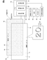
- FIG. 2 is a diagram showing a block diagram showing an electrical configuration of the display device together with an example in which a display image is enlarged.
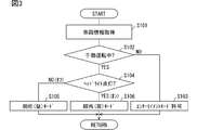
- FIG. 3 is a flowchart showing details of display mode switching control executed by the driver circuit.
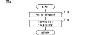
- FIG. 4 is a flowchart showing details of the position control of the light-shielded image performed by the driver circuit.
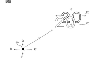
- FIG. 5 is a diagram for explaining the content of the position control of the light-shielded image.
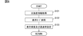
- FIG. 6 is a flowchart showing details of the state control performed by the driver circuit.
- FIG. 1 is a diagram showing a layout around a driver's seat of a vehicle equipped with a display device according to an embodiment of the present disclosure.
- FIG. 2 is a diagram showing a block diagram showing an electrical configuration of the display device together with an example in which a display image is enlarged.
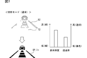
- FIG. 7 is a diagram showing an example of normal display brightness and transmittance setting in the bright place mode.
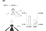
- FIG. 8 is a diagram showing an example of the setting of the display brightness and the transmittance when the direct light such as the sun is present in the bright place mode.
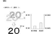
- FIG. 9 is a diagram showing an example of setting of normal display brightness and transmittance in the dark place mode.
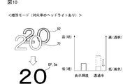
- FIG. 10 is a diagram showing an example of setting of display brightness and transmittance when direct light such as headlights is present in the dark place mode.
- the display device 100 is used in the vehicle A and presents various information related to the vehicle A to the occupant (driver) through the display on the display surface 71.
- the display device 100 includes a video generation device 20, a front camera 30, a driver status monitor (Driver Status Monitor, hereinafter referred to as “DSM”) 40, and a communication bus of an in-vehicle network 50, which are directly or indirectly electrically connected to the display device 100. It is connected.
- DSM Driver Status Monitor
- the video generation device 20 is a control device that integrally controls the display of a plurality of display devices mounted on the vehicle A.
- the video generation device 20 is mainly configured by a circuit that generates a video displayed on each display device.
- the video generation device 20 generates a video signal output to each display device based on the vehicle information acquired from the vehicle-mounted network 50 or the like.
- the video generation device 20 generates a video signal including a display image DP such as a digital speedometer Sm (see also FIGS. 9 and 10) and an ADAS indicator In (see FIGS. 7 and 8), and the display device 100 and the like. Output sequentially toward.
- the front camera 30 shown in FIGS. 1 and 2 has a configuration including an image sensor and a lens unit, and a control unit that controls the image sensor.
- the front camera 30 is fixed to the vehicle A in a posture in which the image capturing direction is directed to the traveling direction of the vehicle A.
- the front camera 30 photographs the foreground range visually recognized by the driver through the windshield WS and generates a front image of the foreground range.
- the front image is used by the automatic driving function (or ADAS function) mounted on the vehicle A.
- an AEB (Autonomous Energy Breaking) function, an ACC (Adaptive Cruise Control) function, an LTC (Lane Trace Control) function, and the like may be included in the automatic driving function.
- the front camera 30 can detect the intensity of light (hereinafter, “direct light”) incident from the outside of the vehicle A through the windshield WS into the vehicle interior from the information of the front image.
- the front camera 30 detects at least direct light that has a high intensity and enters the vehicle interior at an angle close to horizontal, such as the West and Asahi, and headlights and stop lamps of oncoming vehicles.
- the front camera 30 sequentially outputs light intensity information indicating the intensity of direct light to the display device 100.
- the DSM 40 has a near infrared light source, a near infrared camera, and a control unit that controls these.
- the DSM 40 is installed, for example, on the upper surface of the cover of the steering column, with the near-infrared camera facing rearward on the driver's side.
- the DSM 40 captures the vicinity of the driver's face, which is irradiated with near infrared light by the near infrared light source, through the opening 5b of the steering wheel 5 with a near infrared camera.
- the face image captured by the near infrared camera is analyzed by the control unit.
- the control unit estimates, for example, the driver's face orientation, the degree of eye opening, the viewpoint position EP (see FIG. 5), and the line-of-sight direction from the face image.
- the DSM 40 sequentially provides, to the display device 100, at least the information indicating the viewpoint position EP (hereinafter, “eye point information”) among the information estimated by the analysis.
- a large number of in-vehicle ECUs (Electronic Control Units), in-vehicle sensors, etc. are electrically connected directly or indirectly to the communication bus of the in-vehicle network 50 shown in FIG.
- the vehicle-mounted network 50 can provide various vehicle information output to the communication bus to the video generation device 20 and the display device 100.
- the vehicle-mounted network 50 sequentially provides the image generation device 20 with, for example, the traveling speed of the vehicle A as the vehicle information used for image generation.
- headlight lighting control information based on the detection result of the illuminance sensor is output to the vehicle-mounted network 50 by, for example, the body ECU.
- status information indicating the operating state of the automatic driving function is output to the vehicle-mounted network 50 by the automatic driving ECU or the like.
- the vehicle-mounted network 50 sequentially provides the display device 100 with lighting control information, status information of the automatic driving function, and the like.
- the light intensity information from the front camera 30 and the eye point information from the DSM 40 may be provided to the display device 100 via the in-vehicle network 50, like the vehicle information.
- the display device 100 shown in FIGS. 1 and 2 is provided in the vehicle interior of the vehicle A.
- the display device 100 is arranged in front of the driver's seat and functions as a display device that replaces a vehicle combination meter.
- the display device 100 is attached to the upper surface of the instrument panel 2 with the display surface 71 facing the driver's seat.
- the display surface 71 of the display device 100 is located in front of (inward of) the DSM 40 as viewed by the driver, and is visible above the rim portion 5a of the steering wheel 5 (outwheel side).
- the display device 100 is in the form of a colorless and transparent plate that can transmit light as a whole.
- the driver can visually recognize the foreground of the vehicle A without being obstructed by the display device 100.
- the driver visually recognizes the display in which the display image DP is superimposed on the foreground viewed through the display surface 71. That is, the display device 100 is used as a head-up display. Therefore, in the display device 100, the upper edge of the display surface 71 is below the lower limit of the A zone, in other words, the critical region A (see “Revision 3.0 version regarding handling of image display device”). It is arranged.
- the display device 100 includes a transparent display 70, a light-shielding display 80, a driver circuit 60, and the like.
- the transparent display 70 is a transmissive organic EL (Electro Luminescence) display.
- the transparent display 70 is formed in a horizontally long plate shape with a transparent substrate made of a transparent material such as glass, quartz and resin. Of the two surfaces of the transparent display 70, one facing the driver's seat side is the display surface 71, and the other facing the front of the vehicle A and located on the opposite side of the display surface 71 is the back surface 73. Light incident on the display surface 71 and the back surface 73 can pass through the transparent display 70.
- the transparent display 70 displays various information images 72 in full color by a large number of light emitting elements that are two-dimensionally arranged along the display surface 71 and the back surface 73.
- a transparent electrode layer on which a transparent electrode made of thin film ITO (Indium Tin Oxide) is formed, and a light emitting layer electrically connected to the transparent electrode are provided.
- ITO Indium Tin Oxide
- red, green and blue light emitters made of an organic EL material are regularly arranged so as to form individual light emitting pixels.
- the transparent display 70 displays an information image 72 on the display surface 71 by causing each light emitting pixel to emit light by applying a current to each light emitting body through the transparent electrode.
- the light of the information image 72 emitted by the light emitter is emitted from both the display surface 71 and the back surface 73.
- the light-shielding display 80 is a liquid crystal display whose light transmittance can be adjusted.
- the light-shielding display 80 is formed in a horizontally long plate shape by a transparent substrate, a pair of polarization filters and the like.
- the outer edge shape of the light-shielding display 80 is substantially the same as the outer edge shape of the transparent display 70.
- the light-shielding display 80 has a large number of light-shielding pixels whose light transmittance can be changed.
- the light-shielding display 80 displays the light-shielded image 82 (see FIG. 7 and the like) by controlling the transmittance of each light-shielding pixel to be low.
- the light-shielded image 82 is displayed on the rear surface side of the information image 72.
- the light-shielded image 82 blocks direct light traveling from the front of the vehicle through the windshield WS toward the transparent display 70, and improves the brightness contrast of the information image 72.
- a transparent electrode layer having a transparent electrode made of thin film ITO and a liquid crystal layer electrically connected to the transparent electrode are provided on the transparent substrate of the light-shielding display 80.
- Each section of the liquid crystal layer to which a voltage is individually applied through the transparent electrode constitutes one light-shielding pixel.
- the directions of liquid crystal molecules included in the liquid crystal layer are not aligned. Therefore, the polarization direction of light passing through the liquid crystal layer is twisted due to scattering by the liquid crystal molecules.
- the liquid crystal molecules are oriented in a specific direction.
- the light-shielding display 80 continuously changes the light transmittance of each light-shielding pixel from a substantially transparent state to a non-transmissive (black) state by adjusting the voltage applied to each light-shielding pixel.
- the resolution and pixel pitch of the light-shielding pixels in the light-shielding display 80 are substantially the same as the resolution and pixel pitch of the light-emitting pixels in the transparent display 70.
- the two surfaces of the transparent display 70 one facing the transparent display 70 side is the joining surface 81, and the other facing the front of the vehicle A is the back surface 83.
- the bonding surface 81 of the light-shielding display 80 is bonded to the back surface 73 of the transparent display 70 with, for example, a colorless and transparent epoxy resin adhesive.
- the light-shielding display 80 is superposed on the transparent display 70 so that the positions of the light-shielding pixels are aligned with the positions of the light-emitting pixels in the plate thickness direction.
- the light-shielding display 80 may be configured to be substantially transparent (normally white) when no voltage is applied to the light-shielding pixels, or is black when no voltage is applied to the light-shielding pixels.
- the configuration may be a light shielding state (normal leaf rack).
- the driver circuit 60 is an electric circuit that controls the operations of the transparent display 70 and the light-shielding display 80.
- the driver circuit 60 may be electrically connected to each of the displays 70 and 80 while being housed in the housing, or may be integrally provided with either of the displays 70 and 80.
- the driver circuit 60 includes at least one processor, a RAM coupled to the processor, a memory device including a storage medium, and a microcontroller having an input / output interface and the like.
- the memory device of the driver circuit 60 stores a display control program for controlling the operation of each of the displays 70 and 80 in accordance with the video signal acquired from the video generation device 20.
- the driver circuit 60 causes the processor to execute the display control program stored in the memory device, and constructs functional blocks such as the image acquisition unit 61, the information acquisition unit 62, and the display control unit 63.
- the video acquisition unit 61 acquires a video signal from the video generation device 20.
- the information acquisition unit 62 sequentially acquires light intensity information indicating the intensity of direct light traveling toward the transparent display 70 from the front camera 30 (see S121 in FIG. 6). Further, the information acquisition unit 62 sequentially acquires the driver's eye point information from the DSM 40 (see S111 in FIG. 4). The eyepoint information that is continuously acquired becomes tracking information that tracks the viewpoint position EP (see FIG. 5) of the driver who is the viewer of the display device 100. Further, the information acquisition unit 62 acquires lighting control information, status information of the automatic driving function, and the like from the vehicle-mounted network 50 (see S101 in FIG. 3). The lighting control information is used as day and night information indicating whether the vehicle A is in a bright outside light environment or a dark outside light environment.
- the display control unit 63 displays the information image 72 on the display surface 71 of the transparent display 70 based on the video signal acquired by the video acquisition unit 61.
- the display control unit 63 performs control for synchronizing the display change of the light shield image 82 with the display change of the information image 72.
- the display control unit 63 controls the light-shielding pixels that overlap the light-emitting pixels in the light-emitting state to be in the light-shielding state.
- the display control unit 63 causes the light-shielding display 80 to display the light-shielding image 82 having the substantially same shape as the information image 72.
- the display image DP is displayed by superimposing the information image 72 and the light-shielded image 82.
- the display control unit 63 controls display mode switching based on vehicle information (see FIG. 3) and position control of the light-shielding image 82 according to the driver's posture (see FIG. 4). And FIG. 5). Further, the display control unit 63 executes state control of each pixel according to the intensity of direct light (see FIGS. 6 to 9). The driver circuit 60 starts these controls based on the switching of the vehicle power supply to the ON state. Then, these controls are continuously executed until the vehicle power is switched to the off state.
- the display control unit 63 switches the display mode of the display device 100 among a plurality of display modes based on the vehicle information acquired by the information acquisition unit 62.
- the plurality of display modes include an entertainment mode and the like in addition to the bright place mode and the dark place mode.
- the display control unit 63 can set a bright place mode and a dark place mode respectively corresponding to day and night, and switches between the bright place mode and the dark place mode based on the lighting control information acquired by the information acquisition unit 62. Further, the display control unit 63 allows switching to the entertainment mode based on the status information of the automatic driving function.
- the light mode is a display mode assuming that the vehicle A is in a brighter environment than the dark mode.
- the display control unit 63 sets the display mode to the light mode based on the lighting control information indicating the off state of the headlight (see S104 [NO] and S105 in FIG. 3).
- the dark mode is a display mode assuming that the vehicle A is in a darker environment than the bright mode.
- the display control unit 63 sets the display mode to the dark place mode based on the lighting control information indicating the ON state of the headlight (see S104 [YES] and S106).
- the bright place mode in the state control of the light emitting pixel, the maximum luminance of the light emitting pixel allowed is set higher than that in the dark place mode (see FIG. 6). In other words, in the dark place mode, the display brightness of the light emitting pixels is suppressed so that the driver does not feel the display image DP dazzling (see FIG. 8).
- the entertainment mode is a display mode for displaying content such as a moving image on the display device 100 during a period in which the driver is released from the driving operation by the automatic driving function.
- the display control unit 63 permits the switching to the entertainment mode when the status information indicating the autonomous traveling state of the vehicle A is acquired (see S102 [NO] and S103). Under these conditions, the display control unit 63 switches the display mode to entertainment when the driver performs a moving image reproduction operation or a predetermined switch operation. In the entertainment mode, the light transmittance of the light-shielded pixel is controlled to the lowest state.
- the entire light-shielding display 80 is controlled to a uniform light-shielding state, and the display device 100 can be used as a normal non-transmissive display device. If the moving image or the like is not reproduced, the entire display device 100 may be in a transparent state even during autonomous traveling. Such settings can contribute to the driver's feeling of openness.
- the display control unit 63 adjusts the relative position of the light-shielded image 82 with respect to the information image 72 based on the eyepoint information acquired by the information acquisition unit 62, in accordance with the viewpoint position EP of the driver.
- a gap due to the plate thickness of the transparent substrate of each display 70, 80 is inevitably formed between the information image 72 and the light-shielded image 82. Therefore, when the viewpoint position EP of the driver deviates vertically and horizontally from the front of the display surface 71, the relative positional relationship between the information image 72 and the light-shielded image 82 and the eye point changes (see FIG. 5).
- the display control unit 63 sets the shift direction and the shift amount of the light-shielded image 82 based on the acquired eye point information, and the side opposite to the changing direction of the viewpoint position EP.
- the shaded image 82 is moved to (see S112 in FIG. 4).
- the display control unit 63 controls the brightness of the light emitting pixels and the transmittance of the light shielding pixels based on the light intensity information acquired by the information acquisition unit 62.
- the display control unit 63 refers to the current display mode in addition to the current light intensity information (see S122 in FIG. 6) and sets the display brightness and the transmittance corresponding to these (see S123).
- the display control unit 63 sets the display brightness of the information image 72 to be high (see FIGS. 7 and 8).
- the display control unit 63 sets the display brightness of the information image 72 to be low (see FIGS. 9 and 10).
- the display control unit 63 adjusts the transmittance of the light-shielded image 82 to be lower (see FIGS. 8 and 10).
- the light mode is set and the high-intensity information image 72 is displayed. Further, the transmittance of the light-shielded image 82 is adjusted to be low according to the intensity of the direct sunlight.
- the contrast of the display image DP with respect to the sun is secured even for the display image DP that is self-luminous displayed.
- a low-brightness information image 72 whose display brightness is suppressed is displayed by setting the dark place mode. Then, in the scene in which the headlight of the oncoming vehicle is inserted into the vehicle interior, as shown in FIG. 10, while the display brightness of the information image 72 is maintained, depending on the intensity of the light of the headlight that is the direct light, the light-shielded image The transmittance of 82 is adjusted to be low. As a result, the contrast of the display image DP with respect to the headlight is ensured without promoting the glare of the display image DP.
- the transmittance of the shaded image 82 displayed by the shaded display 80 is adjusted to be lower as the direct light toward the transparent display 70 becomes stronger. Therefore, when the direct light is weak, the transmittance of the shaded image 82 is also kept high. As a result, even if the transparent display 70 displays the information image 72 having a complicated shape (for example, the ADAS indicator In, etc.), the information image 72 becomes difficult to see due to the influence of the shaded image 82 on the back side which is synchronously displayed. Can be avoided.
- the display device 100 can continue to display the easy-to-see display image DP regardless of the intensity of the direct light traveling toward the transparent display 70.
- switching between the bright place mode and the dark place mode is performed, and the display brightness of the information image 72 in the dark place mode is suppressed to be lower than the display brightness in the bright place mode. Therefore, it is possible to avoid a situation where the driver feels the information image 72 dazzling at night or in a dark place such as a tunnel.
- the display luminance of the information image 72 is maintained and the transmittance of the light-shielded image 82 is adjusted to be low. According to such control, the display state of the information image 72 that is hard to feel dazzling can be maintained.
- the transmittance of the light-shielded image 82 is adjusted to be low, the display image DP can be displayed in a state where the contrast is secured. Therefore, the display device 100 can display the display image DP in an easy-to-see manner even in a scene where direct light is strongly emitted at night.
- the relative position of the light-shielded image 82 with respect to the information image 72 is adjusted according to the driver's viewpoint position EP. Therefore, even if the display image DP is visually recognized from different viewpoint positions EP due to a difference in the physique of the driver, a posture collapse, and the like, it is difficult for the driver to perceive the shift of the light-shielded image 82 with respect to the information image 72. Further, even when the driver shakes his / her head left or right, the shift between the information image 72 and the light-shielded image 82 is not visible. According to the above, the display discomfort caused by the light-shielded image 82 is reduced.
- the vehicle A when the vehicle A is in the autonomous traveling state, it is possible to set the entire light-shielding display 80 to a uniform light-shielding state by switching to the entertainment mode.
- the driver in the scene where the vehicle A travels autonomously, the driver is released from the task of driving. Therefore, there may be a need to enjoy videos and the like that are not related to driving.
- the use of the light-shielding display 80 in a state in which external light is substantially blocked makes it easier to secure the display quality of moving images. Therefore, the control for uniformly setting the light-shielding display 80 in the light-shielding state can contribute to the added value of the display device 100 in the vehicle A equipped with the automatic driving function.
- the light-shielded image 82 superimposed on the information image 72 has a function of shielding the light of the information image 72 emitted from the rear surface 73 of the transparent display 70. Therefore, the situation in which the driver's driving is hindered due to the occurrence of window reflection of the information image 72 due to the adoption of the transparent display 70 is unlikely to occur.
- the vehicle A corresponds to a “moving body”
- the transparent display 70 corresponds to a “transmissive display”
- the light-shielding display 80 corresponds to a “light-shielding display”.
- the information image and the light-shielded image having the same shape are displayed in a positional relationship that is slightly shifted along the display surface in an oblique direction.
- a part of the outline of the light-shielded image is located outside the outline of the information image so as to protrude from the information image.
- the light-shielded image looks like a shadow of the information image, so that the display image is given a stereoscopic effect.
- the light-shielded image has a slightly similar shape to the information image.
- all the contours of the light-shielded image are located outside the contours of the information image by about 1 to several pixels.
- the light-shielded image can reduce the arrival of the direct light with respect to the entire information image.
- the contrast of the entire display image can be more easily secured in many scenes in which the direct light enters the vehicle interior.
- the transmittance of the outer edge of the light-shielded image protruding from the information image when viewed from the front may be set higher than the transmittance of the intermediate portion hidden by the information image.
- the display device of Modification 3 acquires, for example, the detection result of the illuminance sensor, and controls both the display brightness of the information image and the transmittance of the light-shielded image based on the detection result.
- the same effect as that of the above-described embodiment is achieved, and even when direct light is incident on the light-shielding display on the back side, the luminance of the information image is lost by the ambient brightness, and the display image does not become difficult to see. .
- the configuration for acquiring the light intensity information and the day / night information may be changed appropriately.
- the light intensity and day / night may be estimated based on time information, map information, direction information, weather information, and the like.
- the display device is installed in a vehicle that does not have the automatic driving function.
- switching to the entertainment mode is permitted only when the ignition is in the off state and the vehicle cannot run.
- “whole” of the light-shielding display that is in a uniform light-shielding state indicates a display area used for displaying a moving image or the like. That is, the light-shielding pixels in the display area that are not used for displaying a moving image or the like may be kept transparent.
- the entertainment mode is not prepared as one of the display modes.
- the control for correcting the position of the light-shielded image according to the viewpoint position is not performed.
- the resolution of the transparent display is higher than the resolution of the light-shielding display.
- the resolution of the light-shielding display is higher than that of the transparent display.
- the display device is arranged not on the front of the driver's seat but on the central upper surface of the instrument panel, and functions as a display device that also serves as a center meter and a center display.
- the display device is arranged at the base of the left and right pillars as a display device forming an electronic mirror system. As described above, the installation position of the display device in the vehicle compartment, the number of installations, the size, the aspect ratio, and the like may be appropriately changed.
- non-transitional tangible storage mediums such as a flash memory and a hard disk
- the form of such a storage medium may be appropriately changed.
- the storage medium may be in the form of a memory card or the like, and may be configured to be inserted into a slot portion provided in a housing that stores the driver circuit and electrically connected to the driver circuit.
- the storage medium is not limited to the configuration incorporated in the driver circuit as described above, and may be an optical disk serving as a copy base of the program, a hard disk drive of a general-purpose computer, or the like.
- the driver circuit that executes the display control program may be integrated with another vehicle-mounted ECU such as a video generation device.
- each function provided by the driver circuit can be provided by software and hardware that executes the software, only software, only hardware, or a combination thereof.
- each function can also be provided by a digital circuit including a large number of logic circuits or an analog circuit.
- the moving body equipped with the display device may be a ship other than a vehicle, an aircraft, a transportation device, or the like.
- the occupant of the vehicle need not be the driver who steers the vehicle.
- the display control unit and the method thereof described in the present disclosure may be implemented by a dedicated computer that configures a processor programmed to execute one or more functions embodied by a computer program.
- the apparatus and method described in the present disclosure may be realized by a dedicated hardware logic circuit.
- the device and method described in the present disclosure may be implemented by one or more dedicated computers configured by a combination of a processor that executes a computer program and one or more hardware logic circuits.
- the computer program may be stored in a computer-readable non-transition tangible recording medium as an instruction executed by a computer.
- each step is expressed as, for example, S101. Further, each step can be divided into multiple sub-steps, while multiple steps can be combined into one step.
Landscapes
- Engineering & Computer Science (AREA)
- Combustion & Propulsion (AREA)
- Transportation (AREA)
- Mechanical Engineering (AREA)
- Chemical & Material Sciences (AREA)
- Theoretical Computer Science (AREA)
- Physics & Mathematics (AREA)
- General Physics & Mathematics (AREA)
- Computer Hardware Design (AREA)
- Controls And Circuits For Display Device (AREA)
- Instrument Panels (AREA)
- Devices For Indicating Variable Information By Combining Individual Elements (AREA)
- Control Of Indicators Other Than Cathode Ray Tubes (AREA)
- Electroluminescent Light Sources (AREA)
Applications Claiming Priority (2)
| Application Number | Priority Date | Filing Date | Title |
|---|---|---|---|
| JP2018-214066 | 2018-11-14 | ||
| JP2018214066A JP2020079917A (ja) | 2018-11-14 | 2018-11-14 | 表示装置 |
Publications (1)
| Publication Number | Publication Date |
|---|---|
| WO2020100674A1 true WO2020100674A1 (ja) | 2020-05-22 |
Family
ID=70730937
Family Applications (1)
| Application Number | Title | Priority Date | Filing Date |
|---|---|---|---|
| PCT/JP2019/043393 Ceased WO2020100674A1 (ja) | 2018-11-14 | 2019-11-06 | 表示装置 |
Country Status (2)
| Country | Link |
|---|---|
| JP (1) | JP2020079917A (enExample) |
| WO (1) | WO2020100674A1 (enExample) |
Families Citing this family (3)
| Publication number | Priority date | Publication date | Assignee | Title |
|---|---|---|---|---|
| JP7635007B2 (ja) * | 2021-01-29 | 2025-02-25 | ホーチキ株式会社 | 車載情報表示装置 |
| JP2022153738A (ja) * | 2021-03-30 | 2022-10-13 | テイ・エス テック株式会社 | 自動車 |
| JP7679739B2 (ja) * | 2021-09-10 | 2025-05-20 | コベルコ建機株式会社 | 遠隔操作支援装置、遠隔操作支援システムおよび遠隔操作支援方法 |
Citations (5)
| Publication number | Priority date | Publication date | Assignee | Title |
|---|---|---|---|---|
| WO2013128573A1 (ja) * | 2012-02-28 | 2013-09-06 | パイオニア株式会社 | 表示装置及び表示方法 |
| JP2015217798A (ja) * | 2014-05-16 | 2015-12-07 | 三菱電機株式会社 | 車載情報表示制御装置 |
| JP2016027366A (ja) * | 2014-07-08 | 2016-02-18 | 株式会社デンソー | 車載表示制御装置 |
| JP2016136255A (ja) * | 2015-01-23 | 2016-07-28 | ビステオン グローバル テクノロジーズ インコーポレイテッド | 電子ディスプレイアセンブリ |
| JP2018529113A (ja) * | 2015-06-22 | 2018-10-04 | コンチネンタル オートモーティヴ ゲゼルシャフト ミット ベシュレンクテル ハフツングContinental Automotive GmbH | 制御可能なマスキングディスプレイを有する透明なディスプレイ |
Family Cites Families (3)
| Publication number | Priority date | Publication date | Assignee | Title |
|---|---|---|---|---|
| JP2015141161A (ja) * | 2014-01-30 | 2015-08-03 | 富士通テン株式会社 | 車両用表示装置、及び、表示方法 |
| JP6123761B2 (ja) * | 2014-09-05 | 2017-05-10 | トヨタ自動車株式会社 | 車両用表示装置 |
| JP6354085B2 (ja) * | 2016-05-20 | 2018-07-11 | 本田技研工業株式会社 | 車両制御システム、車両制御方法、および車両制御プログラム |
-
2018
- 2018-11-14 JP JP2018214066A patent/JP2020079917A/ja active Pending
-
2019
- 2019-11-06 WO PCT/JP2019/043393 patent/WO2020100674A1/ja not_active Ceased
Patent Citations (5)
| Publication number | Priority date | Publication date | Assignee | Title |
|---|---|---|---|---|
| WO2013128573A1 (ja) * | 2012-02-28 | 2013-09-06 | パイオニア株式会社 | 表示装置及び表示方法 |
| JP2015217798A (ja) * | 2014-05-16 | 2015-12-07 | 三菱電機株式会社 | 車載情報表示制御装置 |
| JP2016027366A (ja) * | 2014-07-08 | 2016-02-18 | 株式会社デンソー | 車載表示制御装置 |
| JP2016136255A (ja) * | 2015-01-23 | 2016-07-28 | ビステオン グローバル テクノロジーズ インコーポレイテッド | 電子ディスプレイアセンブリ |
| JP2018529113A (ja) * | 2015-06-22 | 2018-10-04 | コンチネンタル オートモーティヴ ゲゼルシャフト ミット ベシュレンクテル ハフツングContinental Automotive GmbH | 制御可能なマスキングディスプレイを有する透明なディスプレイ |
Also Published As
| Publication number | Publication date |
|---|---|
| JP2020079917A (ja) | 2020-05-28 |
Similar Documents
| Publication | Publication Date | Title |
|---|---|---|
| US11964613B2 (en) | Interior trim part of motor vehicle with thin-film display device | |
| US11052732B2 (en) | Shading device for vehicle | |
| US10029621B2 (en) | Rear view camera system using rear view mirror location | |
| CN110967834B (zh) | 显示装置、显示控制方法及存储介质 | |
| US10445594B2 (en) | Onboard display system | |
| US8716644B2 (en) | Glare reduction apparatus | |
| US10583773B2 (en) | Vehicle-mounted system and vehicle | |
| US20220197582A1 (en) | Display device | |
| JP2018529113A (ja) | 制御可能なマスキングディスプレイを有する透明なディスプレイ | |
| JP2005184225A (ja) | 車両用表示装置 | |
| CN102241235A (zh) | 遮挡逆光装置 | |
| JP6302610B1 (ja) | 日除け装置 | |
| US20140267203A1 (en) | Glare reduction system | |
| JP2004271830A (ja) | ディスプレイ装置 | |
| WO2020100674A1 (ja) | 表示装置 | |
| JP6564898B2 (ja) | 車両の日除け装置 | |
| US20250053005A1 (en) | Head-up display apparatus | |
| WO2006027563A1 (en) | View enhancing system for a vehicle | |
| WO2016018320A1 (en) | System for projecting an image within a vehicle interior | |
| KR101520660B1 (ko) | 차량용 영상장치 | |
| GB2417847A (en) | Vehicle blind spot viewing system | |
| JP7099239B2 (ja) | 表示装置及び表示制御装置 | |
| JP2016030487A (ja) | 車両の防眩装置 | |
| JP2021109596A (ja) | 車載用表示装置 | |
| JP6249891B2 (ja) | 表示装置 |
Legal Events
| Date | Code | Title | Description |
|---|---|---|---|
| 121 | Ep: the epo has been informed by wipo that ep was designated in this application |
Ref document number: 19884256 Country of ref document: EP Kind code of ref document: A1 |
|
| NENP | Non-entry into the national phase |
Ref country code: DE |
|
| 122 | Ep: pct application non-entry in european phase |
Ref document number: 19884256 Country of ref document: EP Kind code of ref document: A1 |