WO2020100674A1 - Display device - Google Patents
Display device Download PDFInfo
- Publication number
- WO2020100674A1 WO2020100674A1 PCT/JP2019/043393 JP2019043393W WO2020100674A1 WO 2020100674 A1 WO2020100674 A1 WO 2020100674A1 JP 2019043393 W JP2019043393 W JP 2019043393W WO 2020100674 A1 WO2020100674 A1 WO 2020100674A1
- Authority
- WO
- WIPO (PCT)
- Prior art keywords
- display
- light
- image
- information
- display device
- Prior art date
Links
Images

Classifications
-
- G—PHYSICS
- G09—EDUCATION; CRYPTOGRAPHY; DISPLAY; ADVERTISING; SEALS
- G09G—ARRANGEMENTS OR CIRCUITS FOR CONTROL OF INDICATING DEVICES USING STATIC MEANS TO PRESENT VARIABLE INFORMATION
- G09G3/00—Control arrangements or circuits, of interest only in connection with visual indicators other than cathode-ray tubes
- G09G3/20—Control arrangements or circuits, of interest only in connection with visual indicators other than cathode-ray tubes for presentation of an assembly of a number of characters, e.g. a page, by composing the assembly by combination of individual elements arranged in a matrix no fixed position being assigned to or needed to be assigned to the individual characters or partial characters
-
- B—PERFORMING OPERATIONS; TRANSPORTING
- B60—VEHICLES IN GENERAL
- B60K—ARRANGEMENT OR MOUNTING OF PROPULSION UNITS OR OF TRANSMISSIONS IN VEHICLES; ARRANGEMENT OR MOUNTING OF PLURAL DIVERSE PRIME-MOVERS IN VEHICLES; AUXILIARY DRIVES FOR VEHICLES; INSTRUMENTATION OR DASHBOARDS FOR VEHICLES; ARRANGEMENTS IN CONNECTION WITH COOLING, AIR INTAKE, GAS EXHAUST OR FUEL SUPPLY OF PROPULSION UNITS IN VEHICLES
- B60K35/00—Arrangement of adaptations of instruments
-
- G—PHYSICS
- G09—EDUCATION; CRYPTOGRAPHY; DISPLAY; ADVERTISING; SEALS
- G09F—DISPLAYING; ADVERTISING; SIGNS; LABELS OR NAME-PLATES; SEALS
- G09F9/00—Indicating arrangements for variable information in which the information is built-up on a support by selection or combination of individual elements
- G09F9/46—Indicating arrangements for variable information in which the information is built-up on a support by selection or combination of individual elements in which the desired character is selected from a number of characters arranged one behind the other
-
- G—PHYSICS
- G09—EDUCATION; CRYPTOGRAPHY; DISPLAY; ADVERTISING; SEALS
- G09G—ARRANGEMENTS OR CIRCUITS FOR CONTROL OF INDICATING DEVICES USING STATIC MEANS TO PRESENT VARIABLE INFORMATION
- G09G5/00—Control arrangements or circuits for visual indicators common to cathode-ray tube indicators and other visual indicators
- G09G5/10—Intensity circuits
-
- G—PHYSICS
- G09—EDUCATION; CRYPTOGRAPHY; DISPLAY; ADVERTISING; SEALS
- G09G—ARRANGEMENTS OR CIRCUITS FOR CONTROL OF INDICATING DEVICES USING STATIC MEANS TO PRESENT VARIABLE INFORMATION
- G09G5/00—Control arrangements or circuits for visual indicators common to cathode-ray tube indicators and other visual indicators
- G09G5/36—Control arrangements or circuits for visual indicators common to cathode-ray tube indicators and other visual indicators characterised by the display of a graphic pattern, e.g. using an all-points-addressable [APA] memory
- G09G5/38—Control arrangements or circuits for visual indicators common to cathode-ray tube indicators and other visual indicators characterised by the display of a graphic pattern, e.g. using an all-points-addressable [APA] memory with means for controlling the display position
-
- H—ELECTRICITY
- H10—SEMICONDUCTOR DEVICES; ELECTRIC SOLID-STATE DEVICES NOT OTHERWISE PROVIDED FOR
- H10K—ORGANIC ELECTRIC SOLID-STATE DEVICES
- H10K50/00—Organic light-emitting devices
-
- H—ELECTRICITY
- H10—SEMICONDUCTOR DEVICES; ELECTRIC SOLID-STATE DEVICES NOT OTHERWISE PROVIDED FOR
- H10K—ORGANIC ELECTRIC SOLID-STATE DEVICES
- H10K59/00—Integrated devices, or assemblies of multiple devices, comprising at least one organic light-emitting element covered by group H10K50/00
Definitions
- the present disclosure relates to a display device provided in a room of a moving body.
- Patent Document 1 proposes a display device including a first panel made of a self-luminous element made of a transparent material, and a second panel arranged on the back surface of the first panel and capable of blocking light from the back surface.
- a control unit that controls the two panels causes the first panel to display a video frame and switches the second panel to a transparent state or an opaque state for each of a plurality of regions.
- the display device of Patent Document 1 does not perform control according to the intensity of light coming from the outside. Therefore, when the display device of Patent Document 1 is used in a moving body that is easily affected by external light, it may be difficult to continue the easy-to-see display.
- An object of the present disclosure is to provide a display device capable of continuing easy-to-read information display regardless of the intensity of light directed to the transmissive display, even when the transmissive display such as the first panel is used.
- the display device is provided in the room of the moving body.
- the display device includes a transmissive display that displays an information image on a display surface that can transmit light, and a light-shielding device that is arranged so as to overlap the back surface of the transmissive display opposite to the display surface.
- a light-shielded display that displays an image, an information acquisition unit that acquires the intensity of light that goes to the transmissive display, and a display change of the light-shielded image that synchronizes with the display change of the information image.
- a display control unit that adjusts the transmittance of the light-shielded image to be low.
- the transmittance of the light-shielded image displayed by the light-shielded display is adjusted to be lower as the light toward the light-transmissive display becomes stronger. Therefore, when the light is weak, the transmittance of the light-shielded image is kept high, so even if the information image of a complicated shape is displayed on the transmissive display, due to the influence of the light-shielded image on the back side that is synchronously displayed. The situation where the information image becomes difficult to see can be avoided.
- the display device can continue to display easy-to-read information regardless of the intensity of light directed to the transmissive display.
- FIG. 1 is a diagram showing a layout around a driver's seat of a vehicle equipped with a display device according to an embodiment of the present disclosure.
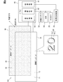
- FIG. 2 is a diagram showing a block diagram showing an electrical configuration of the display device together with an example in which a display image is enlarged.
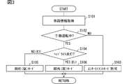
- FIG. 3 is a flowchart showing details of display mode switching control executed by the driver circuit.
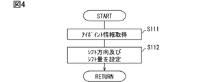
- FIG. 4 is a flowchart showing details of the position control of the light-shielded image performed by the driver circuit.
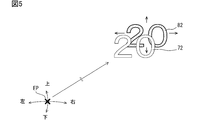
- FIG. 5 is a diagram for explaining the content of the position control of the light-shielded image.
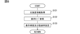
- FIG. 6 is a flowchart showing details of the state control performed by the driver circuit.
- FIG. 1 is a diagram showing a layout around a driver's seat of a vehicle equipped with a display device according to an embodiment of the present disclosure.
- FIG. 2 is a diagram showing a block diagram showing an electrical configuration of the display device together with an example in which a display image is enlarged.
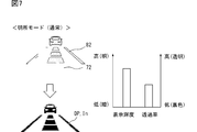
- FIG. 7 is a diagram showing an example of normal display brightness and transmittance setting in the bright place mode.
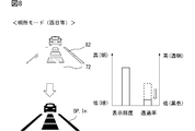
- FIG. 8 is a diagram showing an example of the setting of the display brightness and the transmittance when the direct light such as the sun is present in the bright place mode.
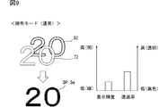
- FIG. 9 is a diagram showing an example of setting of normal display brightness and transmittance in the dark place mode.
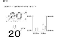
- FIG. 10 is a diagram showing an example of setting of display brightness and transmittance when direct light such as headlights is present in the dark place mode.
- the display device 100 is used in the vehicle A and presents various information related to the vehicle A to the occupant (driver) through the display on the display surface 71.
- the display device 100 includes a video generation device 20, a front camera 30, a driver status monitor (Driver Status Monitor, hereinafter referred to as “DSM”) 40, and a communication bus of an in-vehicle network 50, which are directly or indirectly electrically connected to the display device 100. It is connected.
- DSM Driver Status Monitor
- the video generation device 20 is a control device that integrally controls the display of a plurality of display devices mounted on the vehicle A.
- the video generation device 20 is mainly configured by a circuit that generates a video displayed on each display device.
- the video generation device 20 generates a video signal output to each display device based on the vehicle information acquired from the vehicle-mounted network 50 or the like.
- the video generation device 20 generates a video signal including a display image DP such as a digital speedometer Sm (see also FIGS. 9 and 10) and an ADAS indicator In (see FIGS. 7 and 8), and the display device 100 and the like. Output sequentially toward.
- the front camera 30 shown in FIGS. 1 and 2 has a configuration including an image sensor and a lens unit, and a control unit that controls the image sensor.
- the front camera 30 is fixed to the vehicle A in a posture in which the image capturing direction is directed to the traveling direction of the vehicle A.
- the front camera 30 photographs the foreground range visually recognized by the driver through the windshield WS and generates a front image of the foreground range.
- the front image is used by the automatic driving function (or ADAS function) mounted on the vehicle A.
- an AEB (Autonomous Energy Breaking) function, an ACC (Adaptive Cruise Control) function, an LTC (Lane Trace Control) function, and the like may be included in the automatic driving function.
- the front camera 30 can detect the intensity of light (hereinafter, “direct light”) incident from the outside of the vehicle A through the windshield WS into the vehicle interior from the information of the front image.
- the front camera 30 detects at least direct light that has a high intensity and enters the vehicle interior at an angle close to horizontal, such as the West and Asahi, and headlights and stop lamps of oncoming vehicles.
- the front camera 30 sequentially outputs light intensity information indicating the intensity of direct light to the display device 100.
- the DSM 40 has a near infrared light source, a near infrared camera, and a control unit that controls these.
- the DSM 40 is installed, for example, on the upper surface of the cover of the steering column, with the near-infrared camera facing rearward on the driver's side.
- the DSM 40 captures the vicinity of the driver's face, which is irradiated with near infrared light by the near infrared light source, through the opening 5b of the steering wheel 5 with a near infrared camera.
- the face image captured by the near infrared camera is analyzed by the control unit.
- the control unit estimates, for example, the driver's face orientation, the degree of eye opening, the viewpoint position EP (see FIG. 5), and the line-of-sight direction from the face image.
- the DSM 40 sequentially provides, to the display device 100, at least the information indicating the viewpoint position EP (hereinafter, “eye point information”) among the information estimated by the analysis.
- a large number of in-vehicle ECUs (Electronic Control Units), in-vehicle sensors, etc. are electrically connected directly or indirectly to the communication bus of the in-vehicle network 50 shown in FIG.
- the vehicle-mounted network 50 can provide various vehicle information output to the communication bus to the video generation device 20 and the display device 100.
- the vehicle-mounted network 50 sequentially provides the image generation device 20 with, for example, the traveling speed of the vehicle A as the vehicle information used for image generation.
- headlight lighting control information based on the detection result of the illuminance sensor is output to the vehicle-mounted network 50 by, for example, the body ECU.
- status information indicating the operating state of the automatic driving function is output to the vehicle-mounted network 50 by the automatic driving ECU or the like.
- the vehicle-mounted network 50 sequentially provides the display device 100 with lighting control information, status information of the automatic driving function, and the like.
- the light intensity information from the front camera 30 and the eye point information from the DSM 40 may be provided to the display device 100 via the in-vehicle network 50, like the vehicle information.
- the display device 100 shown in FIGS. 1 and 2 is provided in the vehicle interior of the vehicle A.
- the display device 100 is arranged in front of the driver's seat and functions as a display device that replaces a vehicle combination meter.
- the display device 100 is attached to the upper surface of the instrument panel 2 with the display surface 71 facing the driver's seat.
- the display surface 71 of the display device 100 is located in front of (inward of) the DSM 40 as viewed by the driver, and is visible above the rim portion 5a of the steering wheel 5 (outwheel side).
- the display device 100 is in the form of a colorless and transparent plate that can transmit light as a whole.
- the driver can visually recognize the foreground of the vehicle A without being obstructed by the display device 100.
- the driver visually recognizes the display in which the display image DP is superimposed on the foreground viewed through the display surface 71. That is, the display device 100 is used as a head-up display. Therefore, in the display device 100, the upper edge of the display surface 71 is below the lower limit of the A zone, in other words, the critical region A (see “Revision 3.0 version regarding handling of image display device”). It is arranged.
- the display device 100 includes a transparent display 70, a light-shielding display 80, a driver circuit 60, and the like.
- the transparent display 70 is a transmissive organic EL (Electro Luminescence) display.
- the transparent display 70 is formed in a horizontally long plate shape with a transparent substrate made of a transparent material such as glass, quartz and resin. Of the two surfaces of the transparent display 70, one facing the driver's seat side is the display surface 71, and the other facing the front of the vehicle A and located on the opposite side of the display surface 71 is the back surface 73. Light incident on the display surface 71 and the back surface 73 can pass through the transparent display 70.
- the transparent display 70 displays various information images 72 in full color by a large number of light emitting elements that are two-dimensionally arranged along the display surface 71 and the back surface 73.
- a transparent electrode layer on which a transparent electrode made of thin film ITO (Indium Tin Oxide) is formed, and a light emitting layer electrically connected to the transparent electrode are provided.
- ITO Indium Tin Oxide
- red, green and blue light emitters made of an organic EL material are regularly arranged so as to form individual light emitting pixels.
- the transparent display 70 displays an information image 72 on the display surface 71 by causing each light emitting pixel to emit light by applying a current to each light emitting body through the transparent electrode.
- the light of the information image 72 emitted by the light emitter is emitted from both the display surface 71 and the back surface 73.
- the light-shielding display 80 is a liquid crystal display whose light transmittance can be adjusted.
- the light-shielding display 80 is formed in a horizontally long plate shape by a transparent substrate, a pair of polarization filters and the like.
- the outer edge shape of the light-shielding display 80 is substantially the same as the outer edge shape of the transparent display 70.
- the light-shielding display 80 has a large number of light-shielding pixels whose light transmittance can be changed.
- the light-shielding display 80 displays the light-shielded image 82 (see FIG. 7 and the like) by controlling the transmittance of each light-shielding pixel to be low.
- the light-shielded image 82 is displayed on the rear surface side of the information image 72.
- the light-shielded image 82 blocks direct light traveling from the front of the vehicle through the windshield WS toward the transparent display 70, and improves the brightness contrast of the information image 72.
- a transparent electrode layer having a transparent electrode made of thin film ITO and a liquid crystal layer electrically connected to the transparent electrode are provided on the transparent substrate of the light-shielding display 80.
- Each section of the liquid crystal layer to which a voltage is individually applied through the transparent electrode constitutes one light-shielding pixel.
- the directions of liquid crystal molecules included in the liquid crystal layer are not aligned. Therefore, the polarization direction of light passing through the liquid crystal layer is twisted due to scattering by the liquid crystal molecules.
- the liquid crystal molecules are oriented in a specific direction.
- the light-shielding display 80 continuously changes the light transmittance of each light-shielding pixel from a substantially transparent state to a non-transmissive (black) state by adjusting the voltage applied to each light-shielding pixel.
- the resolution and pixel pitch of the light-shielding pixels in the light-shielding display 80 are substantially the same as the resolution and pixel pitch of the light-emitting pixels in the transparent display 70.
- the two surfaces of the transparent display 70 one facing the transparent display 70 side is the joining surface 81, and the other facing the front of the vehicle A is the back surface 83.
- the bonding surface 81 of the light-shielding display 80 is bonded to the back surface 73 of the transparent display 70 with, for example, a colorless and transparent epoxy resin adhesive.
- the light-shielding display 80 is superposed on the transparent display 70 so that the positions of the light-shielding pixels are aligned with the positions of the light-emitting pixels in the plate thickness direction.
- the light-shielding display 80 may be configured to be substantially transparent (normally white) when no voltage is applied to the light-shielding pixels, or is black when no voltage is applied to the light-shielding pixels.
- the configuration may be a light shielding state (normal leaf rack).
- the driver circuit 60 is an electric circuit that controls the operations of the transparent display 70 and the light-shielding display 80.
- the driver circuit 60 may be electrically connected to each of the displays 70 and 80 while being housed in the housing, or may be integrally provided with either of the displays 70 and 80.
- the driver circuit 60 includes at least one processor, a RAM coupled to the processor, a memory device including a storage medium, and a microcontroller having an input / output interface and the like.
- the memory device of the driver circuit 60 stores a display control program for controlling the operation of each of the displays 70 and 80 in accordance with the video signal acquired from the video generation device 20.
- the driver circuit 60 causes the processor to execute the display control program stored in the memory device, and constructs functional blocks such as the image acquisition unit 61, the information acquisition unit 62, and the display control unit 63.
- the video acquisition unit 61 acquires a video signal from the video generation device 20.
- the information acquisition unit 62 sequentially acquires light intensity information indicating the intensity of direct light traveling toward the transparent display 70 from the front camera 30 (see S121 in FIG. 6). Further, the information acquisition unit 62 sequentially acquires the driver's eye point information from the DSM 40 (see S111 in FIG. 4). The eyepoint information that is continuously acquired becomes tracking information that tracks the viewpoint position EP (see FIG. 5) of the driver who is the viewer of the display device 100. Further, the information acquisition unit 62 acquires lighting control information, status information of the automatic driving function, and the like from the vehicle-mounted network 50 (see S101 in FIG. 3). The lighting control information is used as day and night information indicating whether the vehicle A is in a bright outside light environment or a dark outside light environment.
- the display control unit 63 displays the information image 72 on the display surface 71 of the transparent display 70 based on the video signal acquired by the video acquisition unit 61.
- the display control unit 63 performs control for synchronizing the display change of the light shield image 82 with the display change of the information image 72.
- the display control unit 63 controls the light-shielding pixels that overlap the light-emitting pixels in the light-emitting state to be in the light-shielding state.
- the display control unit 63 causes the light-shielding display 80 to display the light-shielding image 82 having the substantially same shape as the information image 72.
- the display image DP is displayed by superimposing the information image 72 and the light-shielded image 82.
- the display control unit 63 controls display mode switching based on vehicle information (see FIG. 3) and position control of the light-shielding image 82 according to the driver's posture (see FIG. 4). And FIG. 5). Further, the display control unit 63 executes state control of each pixel according to the intensity of direct light (see FIGS. 6 to 9). The driver circuit 60 starts these controls based on the switching of the vehicle power supply to the ON state. Then, these controls are continuously executed until the vehicle power is switched to the off state.
- the display control unit 63 switches the display mode of the display device 100 among a plurality of display modes based on the vehicle information acquired by the information acquisition unit 62.
- the plurality of display modes include an entertainment mode and the like in addition to the bright place mode and the dark place mode.
- the display control unit 63 can set a bright place mode and a dark place mode respectively corresponding to day and night, and switches between the bright place mode and the dark place mode based on the lighting control information acquired by the information acquisition unit 62. Further, the display control unit 63 allows switching to the entertainment mode based on the status information of the automatic driving function.
- the light mode is a display mode assuming that the vehicle A is in a brighter environment than the dark mode.
- the display control unit 63 sets the display mode to the light mode based on the lighting control information indicating the off state of the headlight (see S104 [NO] and S105 in FIG. 3).
- the dark mode is a display mode assuming that the vehicle A is in a darker environment than the bright mode.
- the display control unit 63 sets the display mode to the dark place mode based on the lighting control information indicating the ON state of the headlight (see S104 [YES] and S106).
- the bright place mode in the state control of the light emitting pixel, the maximum luminance of the light emitting pixel allowed is set higher than that in the dark place mode (see FIG. 6). In other words, in the dark place mode, the display brightness of the light emitting pixels is suppressed so that the driver does not feel the display image DP dazzling (see FIG. 8).
- the entertainment mode is a display mode for displaying content such as a moving image on the display device 100 during a period in which the driver is released from the driving operation by the automatic driving function.
- the display control unit 63 permits the switching to the entertainment mode when the status information indicating the autonomous traveling state of the vehicle A is acquired (see S102 [NO] and S103). Under these conditions, the display control unit 63 switches the display mode to entertainment when the driver performs a moving image reproduction operation or a predetermined switch operation. In the entertainment mode, the light transmittance of the light-shielded pixel is controlled to the lowest state.
- the entire light-shielding display 80 is controlled to a uniform light-shielding state, and the display device 100 can be used as a normal non-transmissive display device. If the moving image or the like is not reproduced, the entire display device 100 may be in a transparent state even during autonomous traveling. Such settings can contribute to the driver's feeling of openness.
- the display control unit 63 adjusts the relative position of the light-shielded image 82 with respect to the information image 72 based on the eyepoint information acquired by the information acquisition unit 62, in accordance with the viewpoint position EP of the driver.
- a gap due to the plate thickness of the transparent substrate of each display 70, 80 is inevitably formed between the information image 72 and the light-shielded image 82. Therefore, when the viewpoint position EP of the driver deviates vertically and horizontally from the front of the display surface 71, the relative positional relationship between the information image 72 and the light-shielded image 82 and the eye point changes (see FIG. 5).
- the display control unit 63 sets the shift direction and the shift amount of the light-shielded image 82 based on the acquired eye point information, and the side opposite to the changing direction of the viewpoint position EP.
- the shaded image 82 is moved to (see S112 in FIG. 4).
- the display control unit 63 controls the brightness of the light emitting pixels and the transmittance of the light shielding pixels based on the light intensity information acquired by the information acquisition unit 62.
- the display control unit 63 refers to the current display mode in addition to the current light intensity information (see S122 in FIG. 6) and sets the display brightness and the transmittance corresponding to these (see S123).
- the display control unit 63 sets the display brightness of the information image 72 to be high (see FIGS. 7 and 8).
- the display control unit 63 sets the display brightness of the information image 72 to be low (see FIGS. 9 and 10).
- the display control unit 63 adjusts the transmittance of the light-shielded image 82 to be lower (see FIGS. 8 and 10).
- the light mode is set and the high-intensity information image 72 is displayed. Further, the transmittance of the light-shielded image 82 is adjusted to be low according to the intensity of the direct sunlight.
- the contrast of the display image DP with respect to the sun is secured even for the display image DP that is self-luminous displayed.
- a low-brightness information image 72 whose display brightness is suppressed is displayed by setting the dark place mode. Then, in the scene in which the headlight of the oncoming vehicle is inserted into the vehicle interior, as shown in FIG. 10, while the display brightness of the information image 72 is maintained, depending on the intensity of the light of the headlight that is the direct light, the light-shielded image The transmittance of 82 is adjusted to be low. As a result, the contrast of the display image DP with respect to the headlight is ensured without promoting the glare of the display image DP.
- the transmittance of the shaded image 82 displayed by the shaded display 80 is adjusted to be lower as the direct light toward the transparent display 70 becomes stronger. Therefore, when the direct light is weak, the transmittance of the shaded image 82 is also kept high. As a result, even if the transparent display 70 displays the information image 72 having a complicated shape (for example, the ADAS indicator In, etc.), the information image 72 becomes difficult to see due to the influence of the shaded image 82 on the back side which is synchronously displayed. Can be avoided.
- the display device 100 can continue to display the easy-to-see display image DP regardless of the intensity of the direct light traveling toward the transparent display 70.
- switching between the bright place mode and the dark place mode is performed, and the display brightness of the information image 72 in the dark place mode is suppressed to be lower than the display brightness in the bright place mode. Therefore, it is possible to avoid a situation where the driver feels the information image 72 dazzling at night or in a dark place such as a tunnel.
- the display luminance of the information image 72 is maintained and the transmittance of the light-shielded image 82 is adjusted to be low. According to such control, the display state of the information image 72 that is hard to feel dazzling can be maintained.
- the transmittance of the light-shielded image 82 is adjusted to be low, the display image DP can be displayed in a state where the contrast is secured. Therefore, the display device 100 can display the display image DP in an easy-to-see manner even in a scene where direct light is strongly emitted at night.
- the relative position of the light-shielded image 82 with respect to the information image 72 is adjusted according to the driver's viewpoint position EP. Therefore, even if the display image DP is visually recognized from different viewpoint positions EP due to a difference in the physique of the driver, a posture collapse, and the like, it is difficult for the driver to perceive the shift of the light-shielded image 82 with respect to the information image 72. Further, even when the driver shakes his / her head left or right, the shift between the information image 72 and the light-shielded image 82 is not visible. According to the above, the display discomfort caused by the light-shielded image 82 is reduced.
- the vehicle A when the vehicle A is in the autonomous traveling state, it is possible to set the entire light-shielding display 80 to a uniform light-shielding state by switching to the entertainment mode.
- the driver in the scene where the vehicle A travels autonomously, the driver is released from the task of driving. Therefore, there may be a need to enjoy videos and the like that are not related to driving.
- the use of the light-shielding display 80 in a state in which external light is substantially blocked makes it easier to secure the display quality of moving images. Therefore, the control for uniformly setting the light-shielding display 80 in the light-shielding state can contribute to the added value of the display device 100 in the vehicle A equipped with the automatic driving function.
- the light-shielded image 82 superimposed on the information image 72 has a function of shielding the light of the information image 72 emitted from the rear surface 73 of the transparent display 70. Therefore, the situation in which the driver's driving is hindered due to the occurrence of window reflection of the information image 72 due to the adoption of the transparent display 70 is unlikely to occur.
- the vehicle A corresponds to a “moving body”
- the transparent display 70 corresponds to a “transmissive display”
- the light-shielding display 80 corresponds to a “light-shielding display”.
- the information image and the light-shielded image having the same shape are displayed in a positional relationship that is slightly shifted along the display surface in an oblique direction.
- a part of the outline of the light-shielded image is located outside the outline of the information image so as to protrude from the information image.
- the light-shielded image looks like a shadow of the information image, so that the display image is given a stereoscopic effect.
- the light-shielded image has a slightly similar shape to the information image.
- all the contours of the light-shielded image are located outside the contours of the information image by about 1 to several pixels.
- the light-shielded image can reduce the arrival of the direct light with respect to the entire information image.
- the contrast of the entire display image can be more easily secured in many scenes in which the direct light enters the vehicle interior.
- the transmittance of the outer edge of the light-shielded image protruding from the information image when viewed from the front may be set higher than the transmittance of the intermediate portion hidden by the information image.
- the display device of Modification 3 acquires, for example, the detection result of the illuminance sensor, and controls both the display brightness of the information image and the transmittance of the light-shielded image based on the detection result.
- the same effect as that of the above-described embodiment is achieved, and even when direct light is incident on the light-shielding display on the back side, the luminance of the information image is lost by the ambient brightness, and the display image does not become difficult to see. .
- the configuration for acquiring the light intensity information and the day / night information may be changed appropriately.
- the light intensity and day / night may be estimated based on time information, map information, direction information, weather information, and the like.
- the display device is installed in a vehicle that does not have the automatic driving function.
- switching to the entertainment mode is permitted only when the ignition is in the off state and the vehicle cannot run.
- “whole” of the light-shielding display that is in a uniform light-shielding state indicates a display area used for displaying a moving image or the like. That is, the light-shielding pixels in the display area that are not used for displaying a moving image or the like may be kept transparent.
- the entertainment mode is not prepared as one of the display modes.
- the control for correcting the position of the light-shielded image according to the viewpoint position is not performed.
- the resolution of the transparent display is higher than the resolution of the light-shielding display.
- the resolution of the light-shielding display is higher than that of the transparent display.
- the display device is arranged not on the front of the driver's seat but on the central upper surface of the instrument panel, and functions as a display device that also serves as a center meter and a center display.
- the display device is arranged at the base of the left and right pillars as a display device forming an electronic mirror system. As described above, the installation position of the display device in the vehicle compartment, the number of installations, the size, the aspect ratio, and the like may be appropriately changed.
- non-transitional tangible storage mediums such as a flash memory and a hard disk
- the form of such a storage medium may be appropriately changed.
- the storage medium may be in the form of a memory card or the like, and may be configured to be inserted into a slot portion provided in a housing that stores the driver circuit and electrically connected to the driver circuit.
- the storage medium is not limited to the configuration incorporated in the driver circuit as described above, and may be an optical disk serving as a copy base of the program, a hard disk drive of a general-purpose computer, or the like.
- the driver circuit that executes the display control program may be integrated with another vehicle-mounted ECU such as a video generation device.
- each function provided by the driver circuit can be provided by software and hardware that executes the software, only software, only hardware, or a combination thereof.
- each function can also be provided by a digital circuit including a large number of logic circuits or an analog circuit.
- the moving body equipped with the display device may be a ship other than a vehicle, an aircraft, a transportation device, or the like.
- the occupant of the vehicle need not be the driver who steers the vehicle.
- the display control unit and the method thereof described in the present disclosure may be implemented by a dedicated computer that configures a processor programmed to execute one or more functions embodied by a computer program.
- the apparatus and method described in the present disclosure may be realized by a dedicated hardware logic circuit.
- the device and method described in the present disclosure may be implemented by one or more dedicated computers configured by a combination of a processor that executes a computer program and one or more hardware logic circuits.
- the computer program may be stored in a computer-readable non-transition tangible recording medium as an instruction executed by a computer.
- each step is expressed as, for example, S101. Further, each step can be divided into multiple sub-steps, while multiple steps can be combined into one step.
Abstract
This display device is provided inside a cabin of a moving body (A). The display device is provided with a transmissive display unit (70) that displays an informational image (72) on a display surface (71) capable of transmitting light, a light-blocking display unit (80) that overlaps a rear surface (73) of the transmissive display unit on the side opposite the display surface and that displays a light-blocking image (82) of which the light transmissivity can be adjusted, an information acquisition unit (62) that acquires the intensity of light directed toward the transmissive display unit, and a display control unit (63) that synchronizes a display change of the light-blocking image which a display change of the informational image adjusts the transmissivity of the light-blocking image to be decrease commensurately with respect to the increase in the intensity of the light directed toward the transmissive display unit.
Description
本出願は、2018年11月14日に出願された日本国特許出願2018-214066号に基づくものであり、ここにその記載内容を参照により援用する。
This application is based on Japanese Patent Application No. 2018-214066 filed on November 14, 2018, and the description content is incorporated herein by reference.
本開示は、移動体の室内に設けられる表示装置に関する。
The present disclosure relates to a display device provided in a room of a moving body.
例えば特許文献1には、透明な材質の自体発光素子からなる第1パネルと、第1パネルの背面に配置されて背面から光を遮断可能な第2パネルとを備えるディスプレイ装置が提案されている。特許文献1のディスプレイ装置において、二つのパネルを制御する制御部は、第1パネルに映像フレームを表示させると共に、第2パネルを複数の領域別に透明な状態または不透明な状態に切り替える。
For example, Patent Document 1 proposes a display device including a first panel made of a self-luminous element made of a transparent material, and a second panel arranged on the back surface of the first panel and capable of blocking light from the back surface. . In the display device of Patent Document 1, a control unit that controls the two panels causes the first panel to display a video frame and switches the second panel to a transparent state or an opaque state for each of a plurality of regions.
特許文献1のディスプレイ装置では、外部からくる光の強さに応じた制御が実施されない。そのため、特許文献1のディスプレイ装置を、外部光の影響を受け易い移動体にて用いる場合、見易い表示を継続させることが困難となるおそれがあった。
The display device of Patent Document 1 does not perform control according to the intensity of light coming from the outside. Therefore, when the display device of Patent Document 1 is used in a moving body that is easily affected by external light, it may be difficult to continue the easy-to-see display.
本開示の目的は、第1パネルのような透過表示器を用いていても、当該透過表示器へ向かう光の強さにかかわらず、見易い情報表示を継続可能な表示装置を提供することを目的とする。
An object of the present disclosure is to provide a display device capable of continuing easy-to-read information display regardless of the intensity of light directed to the transmissive display, even when the transmissive display such as the first panel is used. And
本開示の一態様によると、表示装置は、移動体の室内に設けられる。表示装置は、光を透過可能な表示面に、情報画像を表示する透過表示器と、透過表示器の表示面とは反対側の背面に重ねて配置され、光の透過率を調整可能な遮光画像を表示する遮光表示器と、透過表示器へ向かう光の強さを取得する情報取得部と、遮光画像の表示変化を情報画像の表示変化に同期させ、透過表示器へ向かう光が強くなるほど、遮光画像の透過率を低く調整する表示制御部と、を備え。
According to one aspect of the present disclosure, the display device is provided in the room of the moving body. The display device includes a transmissive display that displays an information image on a display surface that can transmit light, and a light-shielding device that is arranged so as to overlap the back surface of the transmissive display opposite to the display surface. A light-shielded display that displays an image, an information acquisition unit that acquires the intensity of light that goes to the transmissive display, and a display change of the light-shielded image that synchronizes with the display change of the information image. A display control unit that adjusts the transmittance of the light-shielded image to be low.
この態様では、遮光表示器によって表示される遮光画像の透過率は、透過表示器へ向かう光が強くなるほど、低く調整される。故に、光が弱い場合には、遮光画像の透過率が高く維持されるため、透過表示器に複雑な形状の情報画像が表示されていても、同期表示される背面側の遮光画像の影響により、情報画像が見難くなる事態は、回避され得る。
In this mode, the transmittance of the light-shielded image displayed by the light-shielded display is adjusted to be lower as the light toward the light-transmissive display becomes stronger. Therefore, when the light is weak, the transmittance of the light-shielded image is kept high, so even if the information image of a complicated shape is displayed on the transmissive display, due to the influence of the light-shielded image on the back side that is synchronously displayed. The situation where the information image becomes difficult to see can be avoided.
一方で、光が強い場合には、遮光画像の透過率が低く調整される。そのため、背面側からの光の大部分が遮光画像によって遮られるようになり、情報画像は、コントラストが確保された見易い表示状態となる。以上のことから、透過表示器へ向かう光の強さにかかわらず、表示装置は、見易い情報表示を継続可能となる。
On the other hand, when the light is strong, the transmittance of the shaded image is adjusted to a low value. Therefore, most of the light from the back side is blocked by the light-shielding image, and the information image is in a display state in which the contrast is secured and is easy to see. From the above, the display device can continue to display easy-to-read information regardless of the intensity of light directed to the transmissive display.
本開示についての上記および他の目的、特徴や利点は、添付図面を参照した下記詳細な説明から、より明確になる。添付図面において、
The above and other objects, features and advantages of the present disclosure will be more apparent from the following detailed description with reference to the accompanying drawings. In the attached drawings,
図1に示す本開示の一実施形態による表示装置100は、車両Aにおいて用いられ、車両Aに関連する種々の情報を、表示面71の表示を通じて乗員(運転者)に提示する。表示装置100には、図2に示す映像生成装置20、フロントカメラ30、ドライバステータスモニタ(Driver Status Monitor,以下「DSM」)40、及び車載ネットワーク50の通信バス等が直接的又は間接的に電気接続されている。
The display device 100 according to the embodiment of the present disclosure shown in FIG. 1 is used in the vehicle A and presents various information related to the vehicle A to the occupant (driver) through the display on the display surface 71. The display device 100 includes a video generation device 20, a front camera 30, a driver status monitor (Driver Status Monitor, hereinafter referred to as “DSM”) 40, and a communication bus of an in-vehicle network 50, which are directly or indirectly electrically connected to the display device 100. It is connected.
尚、以下の説明における前後、上下、左右等の方向に関する表現は、水平面に置かれた車両Aを基準として定義される。そして、右及び左については、運転席に着座した運転者を基準に定義される。
Note that the expressions regarding directions such as front, rear, top, bottom, left and right in the following description are defined with the vehicle A placed on a horizontal plane as a reference. The right and left are defined based on the driver sitting in the driver's seat.
映像生成装置20は、車両Aに搭載された複数の表示デバイスの表示を統合的に制御する制御装置である。映像生成装置20は、各表示デバイスに表示される映像を生成する回路を主体に構成されている。映像生成装置20は、車載ネットワーク50等から取得する車両情報に基づき、各表示デバイスへ向けて出力される映像信号を生成する。映像生成装置20は、例えばデジタルスピードメータSm(図9及び図10も参照)及びADASインジケータIn(図7及び図8参照)等の表示画像DPを含んだ映像信号を生成し、表示装置100等へ向けて逐次出力する。
The video generation device 20 is a control device that integrally controls the display of a plurality of display devices mounted on the vehicle A. The video generation device 20 is mainly configured by a circuit that generates a video displayed on each display device. The video generation device 20 generates a video signal output to each display device based on the vehicle information acquired from the vehicle-mounted network 50 or the like. The video generation device 20 generates a video signal including a display image DP such as a digital speedometer Sm (see also FIGS. 9 and 10) and an ADAS indicator In (see FIGS. 7 and 8), and the display device 100 and the like. Output sequentially toward.
図1及び図2に示すフロントカメラ30は、撮像素子及びレンズ部と、撮像素子を制御する制御ユニットとを有する構成である。フロントカメラ30は、車両Aの進行方向に撮像方向を向けた姿勢にて、車両Aに固定されている。フロントカメラ30は、ウィンドシールドWSを通して運転者に視認される前景範囲を撮影し、当該前景範囲を撮像した前方画像を生成する。前方画像は、車両Aに搭載された自動運転機能(又はADAS機能)にて用いられる。具体的には、AEB(Autonomous Emergency Braking)機能、ACC(Adaptive Cruise Control)機能、LTC(Lane Trace Control)機能等が、自動運転機能
に含まれ得る。 Thefront camera 30 shown in FIGS. 1 and 2 has a configuration including an image sensor and a lens unit, and a control unit that controls the image sensor. The front camera 30 is fixed to the vehicle A in a posture in which the image capturing direction is directed to the traveling direction of the vehicle A. The front camera 30 photographs the foreground range visually recognized by the driver through the windshield WS and generates a front image of the foreground range. The front image is used by the automatic driving function (or ADAS function) mounted on the vehicle A. Specifically, an AEB (Autonomous Energy Breaking) function, an ACC (Adaptive Cruise Control) function, an LTC (Lane Trace Control) function, and the like may be included in the automatic driving function.
に含まれ得る。 The
フロントカメラ30は、前方画像の情報から、車両Aの外部からウィンドシールドWSを通して車室内に入射する光(以下、「直射光」)の強さを検出可能である。フロントカメラ30は、例えば西日及び朝日、並びに対向車のヘッドライト及びストップランプ等、高強度であって、水平に近い角度で車室内に入射する直射光を、少なくとも検出する。フロントカメラ30は、直射光の強さを示した光強度情報を、表示装置100に逐次出力する。
The front camera 30 can detect the intensity of light (hereinafter, “direct light”) incident from the outside of the vehicle A through the windshield WS into the vehicle interior from the information of the front image. The front camera 30 detects at least direct light that has a high intensity and enters the vehicle interior at an angle close to horizontal, such as the West and Asahi, and headlights and stop lamps of oncoming vehicles. The front camera 30 sequentially outputs light intensity information indicating the intensity of direct light to the display device 100.
DSM40は、近赤外光源及び近赤外カメラと、これらを制御する制御ユニットとを有している。DSM40は、近赤外カメラを運転席側となる後方に向けた姿勢にて、例えばステアリングコラムのカバー上面等に設置されている。DSM40は、ステアリングホイール5の開口部5bを通して、近赤外光源によって近赤外光を照射された運転者の顔周辺を、近赤外カメラによって撮影する。近赤外カメラによって撮像された顔画像は、制御ユニットによって解析される。制御ユニットは、例えば運転者の顔向き、目の開き具合、視点位置EP(図5参照)及び視線方向等を、顔画像から推定する。DSM40は、解析によって推定されたこれらの情報のうちで、少なくとも視点位置EPを示す情報(以下、「アイポイント情報」)を、表示装置100に逐次提供する。
The DSM 40 has a near infrared light source, a near infrared camera, and a control unit that controls these. The DSM 40 is installed, for example, on the upper surface of the cover of the steering column, with the near-infrared camera facing rearward on the driver's side. The DSM 40 captures the vicinity of the driver's face, which is irradiated with near infrared light by the near infrared light source, through the opening 5b of the steering wheel 5 with a near infrared camera. The face image captured by the near infrared camera is analyzed by the control unit. The control unit estimates, for example, the driver's face orientation, the degree of eye opening, the viewpoint position EP (see FIG. 5), and the line-of-sight direction from the face image. The DSM 40 sequentially provides, to the display device 100, at least the information indicating the viewpoint position EP (hereinafter, “eye point information”) among the information estimated by the analysis.
図2に示す車載ネットワーク50の通信バスには、多数の車載ECU(Electronic Control Unit)及び車載センサ等が直接的又は間接的に電気接続されている。車載ネットワーク50は、通信バスに出力された種々の車両情報を、映像生成装置20及び表示装置100に提供可能である。車載ネットワーク50は、映像生成に用いられる車両情報として、例えば車両Aの走行速度等を映像生成装置20に逐次提供する。
A large number of in-vehicle ECUs (Electronic Control Units), in-vehicle sensors, etc. are electrically connected directly or indirectly to the communication bus of the in-vehicle network 50 shown in FIG. The vehicle-mounted network 50 can provide various vehicle information output to the communication bus to the video generation device 20 and the display device 100. The vehicle-mounted network 50 sequentially provides the image generation device 20 with, for example, the traveling speed of the vehicle A as the vehicle information used for image generation.
加えて車載ネットワーク50には、照度センサの検出結果に基づくヘッドライトの点灯制御情報が、例えばボディECU等によって出力されている。さらに車載ネットワーク50には、自動運転機能の作動状態を示すステータス情報が、自動運転ECU等によって出力されている。車載ネットワーク50は、点灯制御情報及び自動運転機能のステータス情報等を、表示装置100に逐次提供する。尚、フロントカメラ30による光強度情報及びDSM40によるアイポイント情報は、車両情報と同様に、車載ネットワーク50を経由して、表示装置100に提供されてもよい。
In addition, headlight lighting control information based on the detection result of the illuminance sensor is output to the vehicle-mounted network 50 by, for example, the body ECU. Furthermore, status information indicating the operating state of the automatic driving function is output to the vehicle-mounted network 50 by the automatic driving ECU or the like. The vehicle-mounted network 50 sequentially provides the display device 100 with lighting control information, status information of the automatic driving function, and the like. The light intensity information from the front camera 30 and the eye point information from the DSM 40 may be provided to the display device 100 via the in-vehicle network 50, like the vehicle information.
図1及び図2に示す表示装置100は、車両Aの車室内に設けられている。表示装置100は、運転席の前方に配置されており、車両用のコンビネーションメータを代替する表示デバイスとして機能する。表示装置100は、表示面71を運転席側へ向けた姿勢にて、インスツルメントパネル2の上面に取り付けられている。表示装置100の表示面71は、運転者から見てDSM40よりも前方(奥側)に位置しており、且つ、ステアリングホイール5のリム部5aの上方(アウトホイール側)に視認される。
The display device 100 shown in FIGS. 1 and 2 is provided in the vehicle interior of the vehicle A. The display device 100 is arranged in front of the driver's seat and functions as a display device that replaces a vehicle combination meter. The display device 100 is attached to the upper surface of the instrument panel 2 with the display surface 71 facing the driver's seat. The display surface 71 of the display device 100 is located in front of (inward of) the DSM 40 as viewed by the driver, and is visible above the rim portion 5a of the steering wheel 5 (outwheel side).
表示装置100は、全体として光を透過させることが可能な無色透明な板状を呈している。運転者は、表示装置100に遮られることなく、車両Aの前景を視認できる。運転者は、表示面71を通して見える前景に、表示画像DPが重畳された表示を視認する。即ち、表示装置100は、ヘッドアップディスプレイとして用いられる。そのため、表示装置100は、表示面71の上縁がAゾーン、換言すると、臨界領域A(「画像表示装置の取り扱いについて 改訂第3.0版」参照)の下限よりも下方となるように、配置されている。
The display device 100 is in the form of a colorless and transparent plate that can transmit light as a whole. The driver can visually recognize the foreground of the vehicle A without being obstructed by the display device 100. The driver visually recognizes the display in which the display image DP is superimposed on the foreground viewed through the display surface 71. That is, the display device 100 is used as a head-up display. Therefore, in the display device 100, the upper edge of the display surface 71 is below the lower limit of the A zone, in other words, the critical region A (see “Revision 3.0 version regarding handling of image display device”). It is arranged.
表示装置100は、透明ディスプレイ70、遮光ディスプレイ80及びドライバ回路60等によって構成されている。
The display device 100 includes a transparent display 70, a light-shielding display 80, a driver circuit 60, and the like.
透明ディスプレイ70は、透過型の有機EL(Electro Luminescence)ディスプレイである。透明ディスプレイ70は、ガラス、石英及び樹脂等の透明材料よりなる透明基板により、横長の板状に形成されている。透明ディスプレイ70の両面のうちで、運転席側に向けられる一方が表示面71となり、表示面71の反対側に位置して車両Aの前方を向く他方が背面73となる。表示面71及び背面73に入射した光は、透明ディスプレイ70を透過可能である。透明ディスプレイ70は、表示面71及び背面73に沿って2次元配列された多数の発光素子により、種々の情報画像72をフルカラー表示する。
The transparent display 70 is a transmissive organic EL (Electro Luminescence) display. The transparent display 70 is formed in a horizontally long plate shape with a transparent substrate made of a transparent material such as glass, quartz and resin. Of the two surfaces of the transparent display 70, one facing the driver's seat side is the display surface 71, and the other facing the front of the vehicle A and located on the opposite side of the display surface 71 is the back surface 73. Light incident on the display surface 71 and the back surface 73 can pass through the transparent display 70. The transparent display 70 displays various information images 72 in full color by a large number of light emitting elements that are two-dimensionally arranged along the display surface 71 and the back surface 73.
透明ディスプレイ70の透明基板上には、薄膜状のITO(Indium Tin Oxide)よりなる透明電極が形成された透明電極層と、透明電極に電気接続された発光層とが設けられている。発光層には、有機EL材料よりなる赤、緑及び青の各発光体が、個々の発光画素を形成するように規則的に配列されている。透明ディスプレイ70は、透明電極を通じた各発光体への電流の印加により、各発光画素を発光させることで、表示面71に情報画像72を発光表示する。尚、発光体よって放出される情報画像72の光は、表示面71及び背面73の両面から射出される。
On the transparent substrate of the transparent display 70, a transparent electrode layer on which a transparent electrode made of thin film ITO (Indium Tin Oxide) is formed, and a light emitting layer electrically connected to the transparent electrode are provided. In the light emitting layer, red, green and blue light emitters made of an organic EL material are regularly arranged so as to form individual light emitting pixels. The transparent display 70 displays an information image 72 on the display surface 71 by causing each light emitting pixel to emit light by applying a current to each light emitting body through the transparent electrode. The light of the information image 72 emitted by the light emitter is emitted from both the display surface 71 and the back surface 73.
遮光ディスプレイ80は、光の透過率を調整可能な液晶ディスプレイである。遮光ディスプレイ80は、透明基板及び一対の偏光フィルタ等により、横長の板状に形成されている。遮光ディスプレイ80の外縁形状は、透明ディスプレイ70の外縁形状と実質同一である。遮光ディスプレイ80には、光の透過率を変更可能な遮光画素が多数形成されている。遮光ディスプレイ80は、各遮光画素の透過率を低く調整する制御により、遮光画像82(図7等参照)を表示する。透明ディスプレイ70の背面73が向く側を背面側とすると、遮光画像82は、情報画像72の背面側に表示される。遮光画像82は、車両前方からウィンドシールドWSを通して透明ディスプレイ70へ向かう直射光を遮り、情報画像72の輝度コントラストを向上させる。
The light-shielding display 80 is a liquid crystal display whose light transmittance can be adjusted. The light-shielding display 80 is formed in a horizontally long plate shape by a transparent substrate, a pair of polarization filters and the like. The outer edge shape of the light-shielding display 80 is substantially the same as the outer edge shape of the transparent display 70. The light-shielding display 80 has a large number of light-shielding pixels whose light transmittance can be changed. The light-shielding display 80 displays the light-shielded image 82 (see FIG. 7 and the like) by controlling the transmittance of each light-shielding pixel to be low. If the side of the transparent display 70 facing the rear surface 73 is the rear surface side, the light-shielded image 82 is displayed on the rear surface side of the information image 72. The light-shielded image 82 blocks direct light traveling from the front of the vehicle through the windshield WS toward the transparent display 70, and improves the brightness contrast of the information image 72.
遮光ディスプレイ80の透明基板上には、薄膜状のITOよりなる透明電極が形成された透明電極層と、透明電極に電気接続された液晶層とが設けられている。透明電極を通じて個別に電圧を印加される液晶層の個々の区画が、一つの遮光画素となる。電圧を印加されない遮光画素では、液晶層に含まれる液晶分子の方向が不揃いな状態となる。そのため、液晶層を通過する光の偏光方向は、液晶分子による散乱によってねじ曲げられる。一方で、電圧を印加された遮光画素では、液晶分子が特定の方向を向くようになる。こうした液晶分子の配向により、液晶層を通過する光の偏光方向が一様になる。遮光ディスプレイ80は、各遮光画素に印加する電圧の調整により、各遮光画素の光の透過率を、実質的に透明な状態から不透過(黒色)の状態まで、連続的に変化させる。
On the transparent substrate of the light-shielding display 80, a transparent electrode layer having a transparent electrode made of thin film ITO and a liquid crystal layer electrically connected to the transparent electrode are provided. Each section of the liquid crystal layer to which a voltage is individually applied through the transparent electrode constitutes one light-shielding pixel. In a light-shielded pixel to which no voltage is applied, the directions of liquid crystal molecules included in the liquid crystal layer are not aligned. Therefore, the polarization direction of light passing through the liquid crystal layer is twisted due to scattering by the liquid crystal molecules. On the other hand, in the light-shielded pixel to which the voltage is applied, the liquid crystal molecules are oriented in a specific direction. Such alignment of the liquid crystal molecules makes the polarization direction of light passing through the liquid crystal layer uniform. The light-shielding display 80 continuously changes the light transmittance of each light-shielding pixel from a substantially transparent state to a non-transmissive (black) state by adjusting the voltage applied to each light-shielding pixel.
遮光ディスプレイ80における遮光画素の解像度及び画素ピッチは、透明ディスプレイ70における発光画素の解像度及び画素ピッチと実質同一とされている。透明ディスプレイ70の両面のうちで、透明ディスプレイ70側に向けられる一方が接合面81となり、車両Aの前方を向く他方が背面83となる。遮光ディスプレイ80の接合面81は、例えば無色透明のエポキシ樹脂系の接着材等により、透明ディスプレイ70の背面73に貼り合わされている。板厚方向にて各遮光画素の位置が各発光画素の位置に揃うように、遮光ディスプレイ80は、透明ディスプレイ70に重ね合わされている。
The resolution and pixel pitch of the light-shielding pixels in the light-shielding display 80 are substantially the same as the resolution and pixel pitch of the light-emitting pixels in the transparent display 70. Of the two surfaces of the transparent display 70, one facing the transparent display 70 side is the joining surface 81, and the other facing the front of the vehicle A is the back surface 83. The bonding surface 81 of the light-shielding display 80 is bonded to the back surface 73 of the transparent display 70 with, for example, a colorless and transparent epoxy resin adhesive. The light-shielding display 80 is superposed on the transparent display 70 so that the positions of the light-shielding pixels are aligned with the positions of the light-emitting pixels in the plate thickness direction.
尚、遮光ディスプレイ80は、遮光画素への電圧の印加が無い状態で実質透明な状態となる構成(ノーマリーホワイト)であってもよく、又は遮光画素への電圧の印加が無い状態で黒色の遮光状態となる構成(ノーマリーフラック)であってもよい。
The light-shielding display 80 may be configured to be substantially transparent (normally white) when no voltage is applied to the light-shielding pixels, or is black when no voltage is applied to the light-shielding pixels. The configuration may be a light shielding state (normal leaf rack).
ドライバ回路60は、透明ディスプレイ70及び遮光ディスプレイ80の作動を制御する電気回路である。ドライバ回路60は、筐体に収容された状態で、各ディスプレイ70,80と電気接続されていてもよく、又は各ディスプレイ70,80のいずれかと一体的に設けられていてもよい。ドライバ回路60は、少なくとも一つのプロセッサ、プロセッサに結合されたRAM、記憶媒体を含むメモリ装置、及び入出力インターフェース等を有するマイクロコントローラを備えている。ドライバ回路60のメモリ装置には、映像生成装置20から取得する映像信号に従い、各ディスプレイ70,80の作動を制御する表示制御プログラムが格納されている。ドライバ回路60は、メモリ装置に記憶された表示制御プログラムをプロセッサによって実行し、映像取得部61、情報取得部62、及び表示制御部63等の機能ブロックを構築する。
The driver circuit 60 is an electric circuit that controls the operations of the transparent display 70 and the light-shielding display 80. The driver circuit 60 may be electrically connected to each of the displays 70 and 80 while being housed in the housing, or may be integrally provided with either of the displays 70 and 80. The driver circuit 60 includes at least one processor, a RAM coupled to the processor, a memory device including a storage medium, and a microcontroller having an input / output interface and the like. The memory device of the driver circuit 60 stores a display control program for controlling the operation of each of the displays 70 and 80 in accordance with the video signal acquired from the video generation device 20. The driver circuit 60 causes the processor to execute the display control program stored in the memory device, and constructs functional blocks such as the image acquisition unit 61, the information acquisition unit 62, and the display control unit 63.
映像取得部61は、映像生成装置20から映像信号を取得する。情報取得部62は、透明ディスプレイ70へ向かう直射光の強さを示した光強度情報を、フロントカメラ30から逐次取得する(図6 S121参照)。また情報取得部62は、運転者のアイポイント情報を、DSM40から逐次取得する(図4 S111参照)。継続的に取得されるアイポイント情報は、表示装置100の視認者となる運転者の視点位置EP(図5参照)を追跡する追跡情報となる。さらに情報取得部62は、車載ネットワーク50から、点灯制御情報及び自動運転機能のステータス情報等を取得する(図3 S101参照)。点灯制御情報は、車両Aが明るい外光環境下にあるのか、又は暗い外光環境下にあるのかを示す昼夜情報として使用される。
The video acquisition unit 61 acquires a video signal from the video generation device 20. The information acquisition unit 62 sequentially acquires light intensity information indicating the intensity of direct light traveling toward the transparent display 70 from the front camera 30 (see S121 in FIG. 6). Further, the information acquisition unit 62 sequentially acquires the driver's eye point information from the DSM 40 (see S111 in FIG. 4). The eyepoint information that is continuously acquired becomes tracking information that tracks the viewpoint position EP (see FIG. 5) of the driver who is the viewer of the display device 100. Further, the information acquisition unit 62 acquires lighting control information, status information of the automatic driving function, and the like from the vehicle-mounted network 50 (see S101 in FIG. 3). The lighting control information is used as day and night information indicating whether the vehicle A is in a bright outside light environment or a dark outside light environment.
表示制御部63は、映像取得部61により取得された映像信号に基づき、透明ディスプレイ70の表示面71に情報画像72を表示させる。加えて表示制御部63は、情報画像72の表示変化に、遮光画像82の表示変化を同期させる制御を実施する。具体的に、表示制御部63は、発光状態にある発光画素と重なる遮光画素を遮光状態に制御する。こうした制御により、表示制御部63は、情報画像72と実質同一の形状とされた遮光画像82を、遮光ディスプレイ80に表示させる。こうした情報画像72及び遮光画像82の重ね合わせにより、表示画像DPが表示される。
The display control unit 63 displays the information image 72 on the display surface 71 of the transparent display 70 based on the video signal acquired by the video acquisition unit 61. In addition, the display control unit 63 performs control for synchronizing the display change of the light shield image 82 with the display change of the information image 72. Specifically, the display control unit 63 controls the light-shielding pixels that overlap the light-emitting pixels in the light-emitting state to be in the light-shielding state. By such control, the display control unit 63 causes the light-shielding display 80 to display the light-shielding image 82 having the substantially same shape as the information image 72. The display image DP is displayed by superimposing the information image 72 and the light-shielded image 82.
表示制御部63は、透明ディスプレイ70及び遮光ディスプレイ80の同期制御に加えて、車両情報に基づく表示モードの切り替え制御(図3参照)、運転者姿勢に応じた遮光画像82の位置制御(図4及び図5参照)を実施する。さらに表示制御部63は、直射光の強度に応じた各画素の状態制御(図6~図9参照)を実施する。尚、ドライバ回路60では、車両電源のオン状態への切り替えに基づき、これらの制御が開始される。そして、車両電源のオフ状態への切り替えまで、これらの制御は継続実施される。
In addition to the synchronous control of the transparent display 70 and the light-shielding display 80, the display control unit 63 controls display mode switching based on vehicle information (see FIG. 3) and position control of the light-shielding image 82 according to the driver's posture (see FIG. 4). And FIG. 5). Further, the display control unit 63 executes state control of each pixel according to the intensity of direct light (see FIGS. 6 to 9). The driver circuit 60 starts these controls based on the switching of the vehicle power supply to the ON state. Then, these controls are continuously executed until the vehicle power is switched to the off state.
表示制御部63は、情報取得部62にて取得される車両情報に基づき、表示装置100の表示モードを複数のうちで切り替える。複数の表示モードには、明所モード及び暗所モードに加えて、エンターテイメントモード等が含まれる。表示制御部63は、それぞれ昼夜に対応する明所モード及び暗所モードを設定可能であり、情報取得部62にて取得される点灯制御情報に基づき、明所モードと暗所モードとを切り替える。さらに表示制御部63は、自動運転機能のステータス情報に基づき、エンターテイメントモードへの切り替えを許容する。
The display control unit 63 switches the display mode of the display device 100 among a plurality of display modes based on the vehicle information acquired by the information acquisition unit 62. The plurality of display modes include an entertainment mode and the like in addition to the bright place mode and the dark place mode. The display control unit 63 can set a bright place mode and a dark place mode respectively corresponding to day and night, and switches between the bright place mode and the dark place mode based on the lighting control information acquired by the information acquisition unit 62. Further, the display control unit 63 allows switching to the entertainment mode based on the status information of the automatic driving function.
明所モードは、車両Aが暗所モードよりも明るい環境下にあることを想定した表示モードである。表示制御部63は、ヘッドライトのオフ状態を示す点灯制御情報に基づき、表示モードを明所モードに設定する(図3 S104[NO],S105参照)。一方、暗所モードは、車両Aが明所モードよりも暗い環境下にあることを想定した表示モードである。表示制御部63は、ヘッドライトのオン状態を示す点灯制御情報に基づき、表示モードを暗所モードに設定する(S104[YES],S106参照)。明所モードでは、発光画素の状態制御において、許容される発光画素の最大輝度が、暗所モードよりも高く設定される(図6参照)。換言すれば、暗所モードでは、運転者に表示画像DPが眩しく感じられ難いように、発光画素の表示輝度が抑制される(図8参照)。
The light mode is a display mode assuming that the vehicle A is in a brighter environment than the dark mode. The display control unit 63 sets the display mode to the light mode based on the lighting control information indicating the off state of the headlight (see S104 [NO] and S105 in FIG. 3). On the other hand, the dark mode is a display mode assuming that the vehicle A is in a darker environment than the bright mode. The display control unit 63 sets the display mode to the dark place mode based on the lighting control information indicating the ON state of the headlight (see S104 [YES] and S106). In the bright place mode, in the state control of the light emitting pixel, the maximum luminance of the light emitting pixel allowed is set higher than that in the dark place mode (see FIG. 6). In other words, in the dark place mode, the display brightness of the light emitting pixels is suppressed so that the driver does not feel the display image DP dazzling (see FIG. 8).
エンターテイメントモードは、自動運転機能によって運転者が運転操作から解放された期間において、表示装置100に動画等のコンテンツを表示させる表示モードである。表示制御部63は、車両Aの自律走行状態を示すステータス情報が取得されている場合に、エンターテイメントモードへの切り替えを許可する(S102[NO],S103参照)。こうした状態下、運転者が動画の再生操作又は所定のスイッチ操作等を行うことにより、表示制御部63は、表示モードをエンターテイメントに切り替える。エンターテイメントモードにおいて、遮光画素における光の透過率は、最も低い状態に制御される。その結果、遮光ディスプレイ80の全体が一様な遮光状態に制御され、表示装置100は、通常の不透過型の表示器として使用可能となる。尚、動画等の再生を行わない場合には、自律走行中であっても、表示装置100の全体が透明な状態とされてよい。こうした設定は、運転者の開放感に寄与し得る。
The entertainment mode is a display mode for displaying content such as a moving image on the display device 100 during a period in which the driver is released from the driving operation by the automatic driving function. The display control unit 63 permits the switching to the entertainment mode when the status information indicating the autonomous traveling state of the vehicle A is acquired (see S102 [NO] and S103). Under these conditions, the display control unit 63 switches the display mode to entertainment when the driver performs a moving image reproduction operation or a predetermined switch operation. In the entertainment mode, the light transmittance of the light-shielded pixel is controlled to the lowest state. As a result, the entire light-shielding display 80 is controlled to a uniform light-shielding state, and the display device 100 can be used as a normal non-transmissive display device. If the moving image or the like is not reproduced, the entire display device 100 may be in a transparent state even during autonomous traveling. Such settings can contribute to the driver's feeling of openness.
表示制御部63は、情報取得部62にて取得されるアイポイント情報に基づき、運転者の視点位置EPに合わせて、情報画像72に対する遮光画像82の相対位置を調整する。情報画像72及び遮光画像82の間には、各ディスプレイ70,80の透明基板の板厚に起因する間隙が、不可避的に生じる。そのため、運転者の視点位置EPが表示面71の真正面から上下左右にずれた場合、情報画像72及び遮光画像82と、アイポイントとの相対的な位置関係が変化する(図5参照)。こうした遮光画像82の位置ずれを補正するため、表示制御部63は、取得されたアイポイント情報に基づき、遮光画像82のシフト方向及びシフト量を設定し、視点位置EPの変化方向とは逆側に遮光画像82を移動させる(図4 S112参照)。こうした遮光画像82の位置制御により、視点位置EP、情報画像72及び遮光画像82について、実質一直線上に並ぶ状態が維持される。
The display control unit 63 adjusts the relative position of the light-shielded image 82 with respect to the information image 72 based on the eyepoint information acquired by the information acquisition unit 62, in accordance with the viewpoint position EP of the driver. A gap due to the plate thickness of the transparent substrate of each display 70, 80 is inevitably formed between the information image 72 and the light-shielded image 82. Therefore, when the viewpoint position EP of the driver deviates vertically and horizontally from the front of the display surface 71, the relative positional relationship between the information image 72 and the light-shielded image 82 and the eye point changes (see FIG. 5). In order to correct the positional deviation of the light-shielded image 82, the display control unit 63 sets the shift direction and the shift amount of the light-shielded image 82 based on the acquired eye point information, and the side opposite to the changing direction of the viewpoint position EP. The shaded image 82 is moved to (see S112 in FIG. 4). By such position control of the light-shielded image 82, the viewpoint position EP, the information image 72, and the light-shielded image 82 are maintained in a substantially aligned state.
表示制御部63は、情報取得部62にて取得される光強度情報に基づき、発光画素の輝度制御及び遮光画素の透過率制御を実施する。表示制御部63は、現在の光強度情報に加えて、現在の表示モードを参照し(図6 S122参照)、これらに対応する表示輝度及び透過率を設定する(S123参照)。外光量が多く、車両Aが明るい環境下にある場合、表示制御部63は、情報画像72の表示輝度を高く設定する(図7,図8参照)。対して、外光量が少なく、車両Aが暗い環境下にある場合、表示制御部63は、情報画像72の表示輝度を低く設定する(図9,図10参照)。さらに、車両前方から表示装置100へ向かう直射光が強くなるほど、表示制御部63は、遮光画像82の透過率を低く調整する(図8,図10参照)。
The display control unit 63 controls the brightness of the light emitting pixels and the transmittance of the light shielding pixels based on the light intensity information acquired by the information acquisition unit 62. The display control unit 63 refers to the current display mode in addition to the current light intensity information (see S122 in FIG. 6) and sets the display brightness and the transmittance corresponding to these (see S123). When the amount of outside light is large and the vehicle A is in a bright environment, the display control unit 63 sets the display brightness of the information image 72 to be high (see FIGS. 7 and 8). On the other hand, when the amount of outside light is small and the vehicle A is in a dark environment, the display control unit 63 sets the display brightness of the information image 72 to be low (see FIGS. 9 and 10). Furthermore, as the direct light from the front of the vehicle toward the display device 100 becomes stronger, the display control unit 63 adjusts the transmittance of the light-shielded image 82 to be lower (see FIGS. 8 and 10).
以上の制御によれば、例えば西日が室内に差し込むシーンでは、図8に示すように、明所モードに設定され、高輝度の情報画像72が表示される。さらに、直射光となる西日の強さに応じて、遮光画像82の透過率が低く調整される。こうした遮光画像82の同期制御により、自発光表示される表示画像DPであっても、西日に対する表示画像DPのコントラストが確保される。
According to the above control, for example, in a scene in which the Nishinichi is inserted into the room, as shown in FIG. 8, the light mode is set and the high-intensity information image 72 is displayed. Further, the transmittance of the light-shielded image 82 is adjusted to be low according to the intensity of the direct sunlight. By such synchronization control of the light-shielded image 82, the contrast of the display image DP with respect to the sun is secured even for the display image DP that is self-luminous displayed.
一方、夜間やトンネル内等においては、暗所モードの設定により、表示輝度を抑制された低輝度の情報画像72が表示される。そして、対向車のヘッドライトが車室内に差し込むシーンでは、図10に示すように、情報画像72の表示輝度が維持されつつ、直射光となるヘッドライトの光の強さに応じて、遮光画像82の透過率が低く調整される。その結果、表示画像DPの眩しさを助長させてしまうことなく、ヘッドライトに対する表示画像DPのコントラストが確保される。
On the other hand, at night or in a tunnel or the like, a low-brightness information image 72 whose display brightness is suppressed is displayed by setting the dark place mode. Then, in the scene in which the headlight of the oncoming vehicle is inserted into the vehicle interior, as shown in FIG. 10, while the display brightness of the information image 72 is maintained, depending on the intensity of the light of the headlight that is the direct light, the light-shielded image The transmittance of 82 is adjusted to be low. As a result, the contrast of the display image DP with respect to the headlight is ensured without promoting the glare of the display image DP.
ここまで説明したように、遮光ディスプレイ80によって表示される遮光画像82の透過率は、透明ディスプレイ70へ向かう直射光が強くなるほど、低く調整される。故に、直射光が弱い場合には、遮光画像82の透過率も高く維持される。その結果、透明ディスプレイ70に複雑な形状の情報画像72(例えばADASインジケータIn等)が表示されていても、同期表示される背面側の遮光画像82の影響により、情報画像72が見難くなる事態は、回避され得る。
As described above, the transmittance of the shaded image 82 displayed by the shaded display 80 is adjusted to be lower as the direct light toward the transparent display 70 becomes stronger. Therefore, when the direct light is weak, the transmittance of the shaded image 82 is also kept high. As a result, even if the transparent display 70 displays the information image 72 having a complicated shape (for example, the ADAS indicator In, etc.), the information image 72 becomes difficult to see due to the influence of the shaded image 82 on the back side which is synchronously displayed. Can be avoided.
一方で、直射光が強い場合には、遮光画像82の透過率は、低く調整される。そのため、背面側から入射する直射光の大部分が遮光画像82によって遮られるようになる。その結果、情報画像72は、コントラストが確保された見易い表示状態となる。以上によれば、表示装置100は、透明ディスプレイ70へ向かう直射光の強さにかかわらず、見易い表示画像DPの表示を継続できる。
On the other hand, when the direct light is strong, the transmittance of the shaded image 82 is adjusted to be low. Therefore, most of the direct light incident from the back side is blocked by the light blocking image 82. As a result, the information image 72 is in a display state in which the contrast is secured and is easy to see. According to the above, the display device 100 can continue to display the easy-to-see display image DP regardless of the intensity of the direct light traveling toward the transparent display 70.
加えて本実施形態では、明所モード及び暗所モードの切り替えが実施され、暗所モードにおける情報画像72の表示輝度は、明所モードにおける表示輝度よりも低く抑制される。故に、夜間やトンネル等の暗所においては、情報画像72を運転者が眩しく感じてしまう事態は、回避され得る。
In addition, in the present embodiment, switching between the bright place mode and the dark place mode is performed, and the display brightness of the information image 72 in the dark place mode is suppressed to be lower than the display brightness in the bright place mode. Therefore, it is possible to avoid a situation where the driver feels the information image 72 dazzling at night or in a dark place such as a tunnel.
また本実施形態の暗所モードでは、直射光が強くなると、情報画像72の表示輝度を維持しつつ、遮光画像82の透過率を低くする調整が実施される。こうした制御によれば、眩しく感じられ難い情報画像72の表示状態が維持され得る。加えて、遮光画像82の透過率を低くする調整によれば、表示画像DPは、コントラストを確保された状態で表示され得る。したがって、夜間に直射光が強く照射されるシーンにおいても、表示装置100は、表示画像DPを見易く表示できる。
Further, in the dark place mode of the present embodiment, when the direct light becomes strong, the display luminance of the information image 72 is maintained and the transmittance of the light-shielded image 82 is adjusted to be low. According to such control, the display state of the information image 72 that is hard to feel dazzling can be maintained. In addition, by adjusting the transmittance of the light-shielded image 82 to be low, the display image DP can be displayed in a state where the contrast is secured. Therefore, the display device 100 can display the display image DP in an easy-to-see manner even in a scene where direct light is strongly emitted at night.
さらに本実施形態では、情報画像72に対する遮光画像82の相対位置が、運転者の視点位置EPに合わせて調整される。故に、運転者の体格差や姿勢崩れ等に起因し、異なる視点位置EPから視認される表示画像DPであっても、情報画像72に対する遮光画像82のずれは、運転者に知覚され難い。さらに、運転者が頭を左右に振った場合等でも、情報画像72及び遮光画像82のずれが見えないようにされる。以上によれば、遮光画像82に起因する表示の違和感は、軽減される。
Further, in the present embodiment, the relative position of the light-shielded image 82 with respect to the information image 72 is adjusted according to the driver's viewpoint position EP. Therefore, even if the display image DP is visually recognized from different viewpoint positions EP due to a difference in the physique of the driver, a posture collapse, and the like, it is difficult for the driver to perceive the shift of the light-shielded image 82 with respect to the information image 72. Further, even when the driver shakes his / her head left or right, the shift between the information image 72 and the light-shielded image 82 is not visible. According to the above, the display discomfort caused by the light-shielded image 82 is reduced.
加えて本実施形態では、車両Aが自律走行状態にある場合に、エンターテイメントモードへの切り替えにより、遮光ディスプレイ80の全体を一様な遮光状態に設定することが可能になる。上述したように、車両Aが自律走行するシーンでは、運転者は、運転のタスクから解放される。故に、運転に関連しない動画等を楽しみたいというニーズが生じ得る。こうした用途においては、外光を実質遮断する状態で遮光ディスプレイ80を用いた方が、動画の表示品質は、確保され易くなる。したがって、遮光ディスプレイ80を一様に遮光状態にする制御は、自動運転機能を搭載した車両Aにおいて、表示装置100の付加価値向上に寄与できる。
In addition, in the present embodiment, when the vehicle A is in the autonomous traveling state, it is possible to set the entire light-shielding display 80 to a uniform light-shielding state by switching to the entertainment mode. As described above, in the scene where the vehicle A travels autonomously, the driver is released from the task of driving. Therefore, there may be a need to enjoy videos and the like that are not related to driving. In such an application, the use of the light-shielding display 80 in a state in which external light is substantially blocked makes it easier to secure the display quality of moving images. Therefore, the control for uniformly setting the light-shielding display 80 in the light-shielding state can contribute to the added value of the display device 100 in the vehicle A equipped with the automatic driving function.
また本実施形態では、情報画像72に重ねられた遮光画像82が、透明ディスプレイ70の背面73から射出される情報画像72の光を遮る機能を発揮する。故に、透明ディスプレイ70の採用に伴う情報画像72の窓映りの発生により、運転者の運転が妨げられるような事態は、生じ難くなる。
Further, in the present embodiment, the light-shielded image 82 superimposed on the information image 72 has a function of shielding the light of the information image 72 emitted from the rear surface 73 of the transparent display 70. Therefore, the situation in which the driver's driving is hindered due to the occurrence of window reflection of the information image 72 due to the adoption of the transparent display 70 is unlikely to occur.
尚、上記実施形態では、車両Aが「移動体」に相当し、透明ディスプレイ70が「透過表示器」に相当し、遮光ディスプレイ80が「遮光表示器」に相当する。
In the above embodiment, the vehicle A corresponds to a “moving body”, the transparent display 70 corresponds to a “transmissive display”, and the light-shielding display 80 corresponds to a “light-shielding display”.
(他の実施形態)
以上、本開示の一実施形態について説明したが、本開示は、上記実施形態に限定して解釈されるものではなく、本開示の要旨を逸脱しない範囲内において種々の実施形態及び組み合わせに適用することができる。 (Other embodiments)
Although one embodiment of the present disclosure has been described above, the present disclosure is not construed as being limited to the above embodiment, and is applied to various embodiments and combinations without departing from the gist of the present disclosure. be able to.
上記実施形態の変形例1では、互いに同一形状の情報画像及び遮光画像が、表示面に沿って僅かに斜め方向にずらされた位置関係で表示される。その結果、遮光画像の輪郭の一部は、情報画像からはみ出すようにして、情報画像の輪郭よりも外側に位置する。こうした表示では、遮光画像が情報画像の影のようになるため、表示画像に立体感が付与される。
In the first modification of the above-described embodiment, the information image and the light-shielded image having the same shape are displayed in a positional relationship that is slightly shifted along the display surface in an oblique direction. As a result, a part of the outline of the light-shielded image is located outside the outline of the information image so as to protrude from the information image. In such a display, the light-shielded image looks like a shadow of the information image, so that the display image is given a stereoscopic effect.
上記実施形態の変形例2では、遮光画像は、情報画像よりも僅かに大きな相似形状とされている。表示面を真正面から見たとき、遮光画像の全ての輪郭は、情報画像の輪郭よりも1~数画素程度、外側に位置している。このような変形例2では、遮光ディスプレイに直射光が斜め方向に入射しても、遮光画像は、情報画像全体について、直射光の到達を低減し得る。以上によれば、直射光が車室内に入射する多くのシーンにおいて、表示画像全体のコントラストがさらに確保され易くなる。尚、正面から見て情報画像からはみ出す遮光画像の外縁の透過率は、情報画像に隠れる中間部分の透過率よりも高く設定されてよい。
In the second modification of the above-described embodiment, the light-shielded image has a slightly similar shape to the information image. When the display surface is viewed from the front, all the contours of the light-shielded image are located outside the contours of the information image by about 1 to several pixels. In Modified Example 2 as described above, even if the direct light is obliquely incident on the light-shielding display, the light-shielded image can reduce the arrival of the direct light with respect to the entire information image. According to the above, the contrast of the entire display image can be more easily secured in many scenes in which the direct light enters the vehicle interior. Note that the transmittance of the outer edge of the light-shielded image protruding from the information image when viewed from the front may be set higher than the transmittance of the intermediate portion hidden by the information image.
上記実施形態の変形例3では、明所モード及び暗所モードの切り替えが実施されない。変形例3の表示装置は、例えば照度センサの検出結果を取得し、この検出結果に基づき、情報画像の表示輝度及び遮光画像の透過率の両方を制御する。その結果、上記実施形態と同様の効果を奏し、背面側の遮光ディスプレイに直射光が入射したとしても、情報画像の輝度が周囲の明るさに負けて、表示画像が見難くなる状態にはならない。
In the third modification of the above embodiment, switching between the bright place mode and the dark place mode is not performed. The display device of Modification 3 acquires, for example, the detection result of the illuminance sensor, and controls both the display brightness of the information image and the transmittance of the light-shielded image based on the detection result. As a result, the same effect as that of the above-described embodiment is achieved, and even when direct light is incident on the light-shielding display on the back side, the luminance of the information image is lost by the ambient brightness, and the display image does not become difficult to see. .
以上のように、光強度情報及び昼夜情報を取得する構成は、適宜変更されてよい。例えば、時間情報、地図情報、方位情報及び天気情報等により、光強度及び昼夜の推定が実施されてもよい。
As described above, the configuration for acquiring the light intensity information and the day / night information may be changed appropriately. For example, the light intensity and day / night may be estimated based on time information, map information, direction information, weather information, and the like.
上記実施形態の変形例4では、表示装置は、自動運転機能を非搭載の車両に設置されている。変形例4では、イグニッションがオフ状態とさ、車両が走行できない状態に限り、エンターテイメントモードへの切り替えが許可される。尚、エンターテイメントモードにおいて、一様な遮光状態とされる遮光ディスプレイの「全体」は、動画等の表示に使用される表示領域を示している。即ち、動画等の表示に用いられない表示領域の遮光画素は、透明なまま維持されてよい。
In the fourth modified example of the above embodiment, the display device is installed in a vehicle that does not have the automatic driving function. In the modified example 4, switching to the entertainment mode is permitted only when the ignition is in the off state and the vehicle cannot run. In the entertainment mode, “whole” of the light-shielding display that is in a uniform light-shielding state indicates a display area used for displaying a moving image or the like. That is, the light-shielding pixels in the display area that are not used for displaying a moving image or the like may be kept transparent.
上記実施形態の変形例5では、表示モードの一つとして、エンターテイメントモードが用意されていない。また変形例6では、視点位置に応じて遮光画像の位置を補正する制御は、実施されない。さらに、変形例7では、透明ディスプレイの解像度が、遮光ディスプレイの解像度よりも高い。一方、変形例8では、遮光ディスプレイの解像度が、透明ディスプレイの解像度よりも高い。以上の変形例7,8のように、二つのディスプレイの各画素は、大きさ及び位置を完全に一致させていなくてもよい。
In the fifth modification of the above embodiment, the entertainment mode is not prepared as one of the display modes. In Modification 6, the control for correcting the position of the light-shielded image according to the viewpoint position is not performed. Furthermore, in Modification 7, the resolution of the transparent display is higher than the resolution of the light-shielding display. On the other hand, in Modified Example 8, the resolution of the light-shielding display is higher than that of the transparent display. As in the modified examples 7 and 8 described above, the pixels and pixels of the two displays do not have to have the same size and position.
上記実施形態の変形例9では、表示装置は、運転席の前方ではなく、インスツルメントパネルの中央上面に配置され、センターメータ及びセンターディスプレイを兼ねた表示デバイスとして機能する。また変形例10では、表示装置は、電子ミラーシステムを構成する表示デイバスとして、左右のピラーの根本に配置される。以上のように、車室内における表示装置の設置位置、さらに設置数、サイズ、アスペクト比等は、適宜変更されてよい。
In the ninth modification of the above-described embodiment, the display device is arranged not on the front of the driver's seat but on the central upper surface of the instrument panel, and functions as a display device that also serves as a center meter and a center display. In the modification 10, the display device is arranged at the base of the left and right pillars as a display device forming an electronic mirror system. As described above, the installation position of the display device in the vehicle compartment, the number of installations, the size, the aspect ratio, and the like may be appropriately changed.
表示制御プログラム等を記憶するメモリ装置には、フラッシュメモリ及びハードディスク等の種々の非遷移的実体的記憶媒体(non-transitory tangible storage medium)が採用可能である。こうした記憶媒体の形態も、適宜変更されてよい。例えば記憶媒体は、メモリカード等の形態であり、ドライバ回路を格納する筐体に設けられたスロット部に挿入されて、ドライバ回路に電気接続される構成であってよい。さらに記憶媒体は、上述のようなドライバ回路に内蔵される構成に限定されず、プログラムのコピー基となる光学ディスク及び汎用コンピュータのハードディスクドライブ等であってもよい。
For the memory device that stores the display control program, various non-transitional tangible storage mediums such as a flash memory and a hard disk can be adopted. The form of such a storage medium may be appropriately changed. For example, the storage medium may be in the form of a memory card or the like, and may be configured to be inserted into a slot portion provided in a housing that stores the driver circuit and electrically connected to the driver circuit. Further, the storage medium is not limited to the configuration incorporated in the driver circuit as described above, and may be an optical disk serving as a copy base of the program, a hard disk drive of a general-purpose computer, or the like.
表示制御プログラムを実行するドライバ回路は、映像生成装置等の他の車載ECUと一体的な構成であってよい。また上記実施形態にて、ドライバ回路により提供された各機能は、ソフトウェア及びそれを実行するハードウェア、ソフトウェアのみ、ハードウェアのみ、あるいはそれらの複合的な組合せによっても提供可能である。こうした機能がハードウェアである電子回路によって提供される場合、各機能は、多数の論理回路を含むデジタル回路、又はアナログ回路によっても提供可能である。
The driver circuit that executes the display control program may be integrated with another vehicle-mounted ECU such as a video generation device. Further, in the above-described embodiment, each function provided by the driver circuit can be provided by software and hardware that executes the software, only software, only hardware, or a combination thereof. When such a function is provided by an electronic circuit that is hardware, each function can also be provided by a digital circuit including a large number of logic circuits or an analog circuit.
上記実施形態の透明ディスプレイ及び遮光ディスプレイに相当する具体的な各構成は、適宜変更されてよい。さらに、表示装置を搭載する移動体は、車両以外の船舶、航空機、及び輸送機器等であってもよい。加えて、移動体の乗員は、移動体を操縦する運転者でなくてもよい。
The specific configurations corresponding to the transparent display and the light-shielding display of the above embodiment may be appropriately changed. Further, the moving body equipped with the display device may be a ship other than a vehicle, an aircraft, a transportation device, or the like. In addition, the occupant of the vehicle need not be the driver who steers the vehicle.
以上、本開示の一態様に係る表示装置の実施形態、構成、態様を例示したが、本開示に係る実施形態、構成、態様は、上述した各実施形態、各構成、各態様に限定されるものではない。例えば、異なる実施形態、構成、態様にそれぞれ開示された技術的部を適宜組み合わせて得られる実施形態、構成、態様についても本開示に係る実施形態、構成、態様の範囲に含まれる。
Although the embodiments, configurations, and aspects of the display device according to one aspect of the present disclosure have been illustrated above, the embodiments, configurations, and aspects according to the present disclosure are limited to the above-described respective embodiments, configurations, and aspects. Not a thing. For example, embodiments, configurations, and aspects obtained by appropriately combining the technical portions disclosed in different embodiments, configurations, and aspects are also included in the scope of the embodiments, configurations, and aspects according to the present disclosure.
本開示に記載の表示制御部およびその手法は、コンピュータプログラムにより具体化された一つないしは複数の機能を実行するようにプログラムされたプロセッサを構成する専用コンピュータにより、実現されてもよい。あるいは、本開示に記載の装置およびその手法は、専用ハードウエア論理回路により、実現されてもよい。もしくは、本開示に記載の装置およびその手法は、コンピュータプログラムを実行するプロセッサと一つ以上のハードウエア論理回路との組み合わせにより構成された一つ以上の専用コンピュータにより、実現されてもよい。また、コンピュータプログラムは、コンピュータにより実行されるインストラクションとして、コンピュータ読み取り可能な非遷移有形記録媒体に記憶されていてもよい。
The display control unit and the method thereof described in the present disclosure may be implemented by a dedicated computer that configures a processor programmed to execute one or more functions embodied by a computer program. Alternatively, the apparatus and method described in the present disclosure may be realized by a dedicated hardware logic circuit. Alternatively, the device and method described in the present disclosure may be implemented by one or more dedicated computers configured by a combination of a processor that executes a computer program and one or more hardware logic circuits. Further, the computer program may be stored in a computer-readable non-transition tangible recording medium as an instruction executed by a computer.
ここで、本開示に記載されるフローチャート、あるいは、フローチャートの処理は、複数のステップ(あるいはセクションと言及される)から構成され、各ステップは、たとえば、S101と表現される。さらに、各ステップは、複数のサブステップに分割されることができる、一方、複数のステップが合わさって一つのステップにすることも可能である。
Here, the flowchart described in the present disclosure or the processing of the flowchart is composed of a plurality of steps (or referred to as sections), and each step is expressed as, for example, S101. Further, each step can be divided into multiple sub-steps, while multiple steps can be combined into one step.
Here, the flowchart described in the present disclosure or the processing of the flowchart is composed of a plurality of steps (or referred to as sections), and each step is expressed as, for example, S101. Further, each step can be divided into multiple sub-steps, while multiple steps can be combined into one step.
Claims (6)
- 移動体(A)の室内に設けられる表示装置であって、
光を透過可能な表示面(71)に、情報画像(72)を表示する透過表示器(70)と、
前記透過表示器の前記表示面とは反対側の背面(73)に重ねて配置され、光の透過率を調整可能な遮光画像(82)を表示する遮光表示器(80)と、
前記透過表示器へ向かう光の強さを取得する情報取得部(62)と、
前記遮光画像の表示変化を前記情報画像の表示変化に同期させ、前記透過表示器へ向かう光が強くなるほど、前記遮光画像の透過率を低く調整する表示制御部(63)と、
を備える表示装置。 A display device provided in a room of a moving body (A),
A transmissive display (70) for displaying an information image (72) on a display surface (71) capable of transmitting light;
A light-shielding indicator (80) which is arranged so as to overlap a back surface (73) of the transmissive display opposite to the display surface, and which displays a light-shielding image (82) with adjustable light transmittance;
An information acquisition unit (62) for acquiring the intensity of light directed to the transmissive display,
A display control unit (63) that synchronizes the display change of the light-shielded image with the display change of the information image, and adjusts the transmittance of the light-shielded image to be lower as the light toward the transmissive display becomes stronger;
A display device including. - 前記表示制御部は、
前記移動体が明るい環境下にあることを想定した明所モードと、前記移動体が前記明所モードよりも暗い環境下にあることを想定した暗所モードとを設定可能であり、
前記暗所モードにおける前記情報画像の表示輝度を、前記明所モードにおける表示輝度よりも低くする請求項1に記載の表示装置。 The display control unit,
It is possible to set a bright place mode assuming that the moving body is in a bright environment, and a dark place mode assuming that the moving body is in a darker environment than the bright place mode,
The display device according to claim 1, wherein the display brightness of the information image in the dark place mode is lower than the display brightness in the bright place mode. - 前記表示制御部は、前記暗所モードにて、前記透過表示器へ向かう光が強くなると、前記情報画像の表示輝度を維持しつつ、前記遮光画像の透過率を低く調整する請求項2に記載の表示装置。 The display control unit adjusts the transmittance of the light-shielded image to be low while maintaining the display brightness of the information image when the light toward the transmissive display becomes strong in the dark place mode. Display device.
- 前記情報取得部は、前記情報画像を視認する視認者の視点位置(EP)の情報をさらに取得し、
前記表示制御部は、前記視点位置に合わせて、前記情報画像に対する前記遮光画像の相対位置を調整する請求項1~3のいずれか一項に記載の表示装置。 The information acquisition unit further acquires information on a viewpoint position (EP) of a viewer who visually recognizes the information image,
4. The display device according to claim 1, wherein the display control unit adjusts a relative position of the light-shielded image with respect to the information image in accordance with the viewpoint position. - 前記遮光画像の輪郭は、前記情報画像の輪郭よりも外側に位置している請求項1~4のいずれか一項に記載の表示装置。 The display device according to any one of claims 1 to 4, wherein the outline of the light-shielded image is located outside the outline of the information image.
- 前記情報取得部は、前記移動体が自律走行状態にあることを示す情報をさらに取得し、
前記表示制御部は、前記移動体が自律走行状態にある場合、前記遮光表示器の全体を一様な遮光状態に制御する請求項1~5のいずれか一項に記載の表示装置。
The information acquisition unit further acquires information indicating that the mobile body is in an autonomous traveling state,
The display device according to any one of claims 1 to 5, wherein the display control unit controls the entire light-shielding indicator to a uniform light-shielding state when the moving body is in an autonomous traveling state.
Applications Claiming Priority (2)
| Application Number | Priority Date | Filing Date | Title |
|---|---|---|---|
| JP2018-214066 | 2018-11-14 | ||
| JP2018214066A JP2020079917A (en) | 2018-11-14 | 2018-11-14 | Display device |
Publications (1)
| Publication Number | Publication Date |
|---|---|
| WO2020100674A1 true WO2020100674A1 (en) | 2020-05-22 |
Family
ID=70730937
Family Applications (1)
| Application Number | Title | Priority Date | Filing Date |
|---|---|---|---|
| PCT/JP2019/043393 WO2020100674A1 (en) | 2018-11-14 | 2019-11-06 | Display device |
Country Status (2)
| Country | Link |
|---|---|
| JP (1) | JP2020079917A (en) |
| WO (1) | WO2020100674A1 (en) |
Citations (5)
| Publication number | Priority date | Publication date | Assignee | Title |
|---|---|---|---|---|
| WO2013128573A1 (en) * | 2012-02-28 | 2013-09-06 | パイオニア株式会社 | Display device and display method |
| JP2015217798A (en) * | 2014-05-16 | 2015-12-07 | 三菱電機株式会社 | On-vehicle information display control device |
| JP2016027366A (en) * | 2014-07-08 | 2016-02-18 | 株式会社デンソー | On-vehicle display control device |
| JP2016136255A (en) * | 2015-01-23 | 2016-07-28 | ビステオン グローバル テクノロジーズ インコーポレイテッド | Electronic display assembly |
| JP2018529113A (en) * | 2015-06-22 | 2018-10-04 | コンチネンタル オートモーティヴ ゲゼルシャフト ミット ベシュレンクテル ハフツングContinental Automotive GmbH | Transparent display with controllable masking display |
Family Cites Families (3)
| Publication number | Priority date | Publication date | Assignee | Title |
|---|---|---|---|---|
| JP2015141161A (en) * | 2014-01-30 | 2015-08-03 | 富士通テン株式会社 | Display device for vehicle, and display method |
| JP6123761B2 (en) * | 2014-09-05 | 2017-05-10 | トヨタ自動車株式会社 | Vehicle display device |
| JP6354085B2 (en) * | 2016-05-20 | 2018-07-11 | 本田技研工業株式会社 | Vehicle control system, vehicle control method, and vehicle control program |
-
2018
- 2018-11-14 JP JP2018214066A patent/JP2020079917A/en active Pending
-
2019
- 2019-11-06 WO PCT/JP2019/043393 patent/WO2020100674A1/en active Application Filing
Patent Citations (5)
| Publication number | Priority date | Publication date | Assignee | Title |
|---|---|---|---|---|
| WO2013128573A1 (en) * | 2012-02-28 | 2013-09-06 | パイオニア株式会社 | Display device and display method |
| JP2015217798A (en) * | 2014-05-16 | 2015-12-07 | 三菱電機株式会社 | On-vehicle information display control device |
| JP2016027366A (en) * | 2014-07-08 | 2016-02-18 | 株式会社デンソー | On-vehicle display control device |
| JP2016136255A (en) * | 2015-01-23 | 2016-07-28 | ビステオン グローバル テクノロジーズ インコーポレイテッド | Electronic display assembly |
| JP2018529113A (en) * | 2015-06-22 | 2018-10-04 | コンチネンタル オートモーティヴ ゲゼルシャフト ミット ベシュレンクテル ハフツングContinental Automotive GmbH | Transparent display with controllable masking display |
Also Published As
| Publication number | Publication date |
|---|---|
| JP2020079917A (en) | 2020-05-28 |
Similar Documents
| Publication | Publication Date | Title |
|---|---|---|
| US20220402431A1 (en) | Interior trim part of motor vehicle with thin-film display device | |
| US10976546B2 (en) | Head-up display apparatus having a functional film with a controllable transmittance | |
| JP6333488B1 (en) | Vehicle sunshade | |
| US8624977B2 (en) | Vehicle peripheral image displaying system | |
| US10583773B2 (en) | Vehicle-mounted system and vehicle | |
| JP2018529113A (en) | Transparent display with controllable masking display | |
| US10445594B2 (en) | Onboard display system | |
| WO2006027563A1 (en) | View enhancing system for a vehicle | |
| JP2005184225A (en) | Vehicular display | |
| US9256325B2 (en) | Curved display apparatus for vehicle | |
| US20140267203A1 (en) | Glare reduction system | |
| JP2020057915A (en) | Display apparatus, display control method, and program | |
| US7609227B2 (en) | Liquid crystal display apparatus | |
| US20220197582A1 (en) | Display device | |
| JP2004271830A (en) | Display apparatus | |
| JP6302610B1 (en) | Awning device | |
| KR101520660B1 (en) | display device for automobile | |
| JP2016030487A (en) | Anti-glare device of vehicle | |
| WO2016018320A1 (en) | System for projecting an image within a vehicle interior | |
| GB2417847A (en) | Vehicle blind spot viewing system | |
| JP6564898B2 (en) | Vehicle sunshade | |
| WO2020100674A1 (en) | Display device | |
| JP6726343B2 (en) | Vehicle awning device | |
| US20220091415A1 (en) | Head-up display apparatus | |
| CN113448115A (en) | Display device and control circuit |
Legal Events
| Date | Code | Title | Description |
|---|---|---|---|
| 121 | Ep: the epo has been informed by wipo that ep was designated in this application |
Ref document number: 19884256 Country of ref document: EP Kind code of ref document: A1 |
|
| NENP | Non-entry into the national phase |
Ref country code: DE |
|
| 122 | Ep: pct application non-entry in european phase |
Ref document number: 19884256 Country of ref document: EP Kind code of ref document: A1 |