WO2020095589A1 - 生体用電極、生体センサーおよび生体信号測定システム - Google Patents
生体用電極、生体センサーおよび生体信号測定システム Download PDFInfo
- Publication number
- WO2020095589A1 WO2020095589A1 PCT/JP2019/039176 JP2019039176W WO2020095589A1 WO 2020095589 A1 WO2020095589 A1 WO 2020095589A1 JP 2019039176 W JP2019039176 W JP 2019039176W WO 2020095589 A1 WO2020095589 A1 WO 2020095589A1
- Authority
- WO
- WIPO (PCT)
- Prior art keywords
- conductive
- biomedical electrode
- group
- resin layer
- fibers
- Prior art date
- Legal status (The legal status is an assumption and is not a legal conclusion. Google has not performed a legal analysis and makes no representation as to the accuracy of the status listed.)
- Ceased
Links
Images


Classifications
-
- A—HUMAN NECESSITIES
- A61—MEDICAL OR VETERINARY SCIENCE; HYGIENE
- A61B—DIAGNOSIS; SURGERY; IDENTIFICATION
- A61B5/00—Measuring for diagnostic purposes; Identification of persons
- A61B5/24—Detecting, measuring or recording bioelectric or biomagnetic signals of the body or parts thereof
- A61B5/25—Bioelectric electrodes therefor
- A61B5/251—Means for maintaining electrode contact with the body
-
- A—HUMAN NECESSITIES
- A61—MEDICAL OR VETERINARY SCIENCE; HYGIENE
- A61B—DIAGNOSIS; SURGERY; IDENTIFICATION
- A61B5/00—Measuring for diagnostic purposes; Identification of persons
- A61B5/24—Detecting, measuring or recording bioelectric or biomagnetic signals of the body or parts thereof
- A61B5/25—Bioelectric electrodes therefor
- A61B5/263—Bioelectric electrodes therefor characterised by the electrode materials
- A61B5/268—Bioelectric electrodes therefor characterised by the electrode materials containing conductive polymers, e.g. PEDOT:PSS polymers
-
- A—HUMAN NECESSITIES
- A61—MEDICAL OR VETERINARY SCIENCE; HYGIENE
- A61B—DIAGNOSIS; SURGERY; IDENTIFICATION
- A61B5/00—Measuring for diagnostic purposes; Identification of persons
- A61B5/16—Devices for psychotechnics; Testing reaction times ; Devices for evaluating the psychological state
- A61B5/168—Evaluating attention deficit, hyperactivity
-
- A—HUMAN NECESSITIES
- A61—MEDICAL OR VETERINARY SCIENCE; HYGIENE
- A61B—DIAGNOSIS; SURGERY; IDENTIFICATION
- A61B5/00—Measuring for diagnostic purposes; Identification of persons
- A61B5/24—Detecting, measuring or recording bioelectric or biomagnetic signals of the body or parts thereof
- A61B5/25—Bioelectric electrodes therefor
- A61B5/263—Bioelectric electrodes therefor characterised by the electrode materials
-
- A—HUMAN NECESSITIES
- A61—MEDICAL OR VETERINARY SCIENCE; HYGIENE
- A61B—DIAGNOSIS; SURGERY; IDENTIFICATION
- A61B5/00—Measuring for diagnostic purposes; Identification of persons
- A61B5/24—Detecting, measuring or recording bioelectric or biomagnetic signals of the body or parts thereof
- A61B5/25—Bioelectric electrodes therefor
- A61B5/263—Bioelectric electrodes therefor characterised by the electrode materials
- A61B5/265—Bioelectric electrodes therefor characterised by the electrode materials containing silver or silver chloride
-
- A—HUMAN NECESSITIES
- A61—MEDICAL OR VETERINARY SCIENCE; HYGIENE
- A61B—DIAGNOSIS; SURGERY; IDENTIFICATION
- A61B5/00—Measuring for diagnostic purposes; Identification of persons
- A61B5/24—Detecting, measuring or recording bioelectric or biomagnetic signals of the body or parts thereof
- A61B5/25—Bioelectric electrodes therefor
- A61B5/263—Bioelectric electrodes therefor characterised by the electrode materials
- A61B5/27—Conductive fabrics or textiles
-
- A—HUMAN NECESSITIES
- A61—MEDICAL OR VETERINARY SCIENCE; HYGIENE
- A61B—DIAGNOSIS; SURGERY; IDENTIFICATION
- A61B5/00—Measuring for diagnostic purposes; Identification of persons
- A61B5/24—Detecting, measuring or recording bioelectric or biomagnetic signals of the body or parts thereof
- A61B5/25—Bioelectric electrodes therefor
- A61B5/279—Bioelectric electrodes therefor specially adapted for particular uses
- A61B5/291—Bioelectric electrodes therefor specially adapted for particular uses for electroencephalography [EEG]
-
- A—HUMAN NECESSITIES
- A61—MEDICAL OR VETERINARY SCIENCE; HYGIENE
- A61B—DIAGNOSIS; SURGERY; IDENTIFICATION
- A61B2562/00—Details of sensors; Constructional details of sensor housings or probes; Accessories for sensors
- A61B2562/02—Details of sensors specially adapted for in-vivo measurements
-
- A—HUMAN NECESSITIES
- A61—MEDICAL OR VETERINARY SCIENCE; HYGIENE
- A61B—DIAGNOSIS; SURGERY; IDENTIFICATION
- A61B2562/00—Details of sensors; Constructional details of sensor housings or probes; Accessories for sensors
- A61B2562/02—Details of sensors specially adapted for in-vivo measurements
- A61B2562/0285—Nanoscale sensors
-
- A—HUMAN NECESSITIES
- A61—MEDICAL OR VETERINARY SCIENCE; HYGIENE
- A61B—DIAGNOSIS; SURGERY; IDENTIFICATION
- A61B2562/00—Details of sensors; Constructional details of sensor housings or probes; Accessories for sensors
- A61B2562/04—Arrangements of multiple sensors of the same type
-
- A—HUMAN NECESSITIES
- A61—MEDICAL OR VETERINARY SCIENCE; HYGIENE
- A61B—DIAGNOSIS; SURGERY; IDENTIFICATION
- A61B2562/00—Details of sensors; Constructional details of sensor housings or probes; Accessories for sensors
- A61B2562/14—Coupling media or elements to improve sensor contact with skin or tissue
-
- A—HUMAN NECESSITIES
- A61—MEDICAL OR VETERINARY SCIENCE; HYGIENE
- A61B—DIAGNOSIS; SURGERY; IDENTIFICATION
- A61B2562/00—Details of sensors; Constructional details of sensor housings or probes; Accessories for sensors
- A61B2562/16—Details of sensor housings or probes; Details of structural supports for sensors
-
- A—HUMAN NECESSITIES
- A61—MEDICAL OR VETERINARY SCIENCE; HYGIENE
- A61B—DIAGNOSIS; SURGERY; IDENTIFICATION
- A61B5/00—Measuring for diagnostic purposes; Identification of persons
- A61B5/0002—Remote monitoring of patients using telemetry, e.g. transmission of vital signals via a communication network
- A61B5/0004—Remote monitoring of patients using telemetry, e.g. transmission of vital signals via a communication network characterised by the type of physiological signal transmitted
- A61B5/0006—ECG or EEG signals
-
- A—HUMAN NECESSITIES
- A61—MEDICAL OR VETERINARY SCIENCE; HYGIENE
- A61B—DIAGNOSIS; SURGERY; IDENTIFICATION
- A61B5/00—Measuring for diagnostic purposes; Identification of persons
- A61B5/0048—Detecting, measuring or recording by applying mechanical forces or stimuli
-
- A—HUMAN NECESSITIES
- A61—MEDICAL OR VETERINARY SCIENCE; HYGIENE
- A61B—DIAGNOSIS; SURGERY; IDENTIFICATION
- A61B5/00—Measuring for diagnostic purposes; Identification of persons
- A61B5/02—Detecting, measuring or recording for evaluating the cardiovascular system, e.g. pulse, heart rate, blood pressure or blood flow
- A61B5/024—Measuring pulse rate or heart rate
- A61B5/02416—Measuring pulse rate or heart rate using photoplethysmograph signals, e.g. generated by infrared radiation
- A61B5/02427—Details of sensor
-
- A—HUMAN NECESSITIES
- A61—MEDICAL OR VETERINARY SCIENCE; HYGIENE
- A61B—DIAGNOSIS; SURGERY; IDENTIFICATION
- A61B5/00—Measuring for diagnostic purposes; Identification of persons
- A61B5/02—Detecting, measuring or recording for evaluating the cardiovascular system, e.g. pulse, heart rate, blood pressure or blood flow
- A61B5/024—Measuring pulse rate or heart rate
- A61B5/02438—Measuring pulse rate or heart rate with portable devices, e.g. worn by the patient
-
- A—HUMAN NECESSITIES
- A61—MEDICAL OR VETERINARY SCIENCE; HYGIENE
- A61B—DIAGNOSIS; SURGERY; IDENTIFICATION
- A61B5/00—Measuring for diagnostic purposes; Identification of persons
- A61B5/02—Detecting, measuring or recording for evaluating the cardiovascular system, e.g. pulse, heart rate, blood pressure or blood flow
- A61B5/024—Measuring pulse rate or heart rate
- A61B5/0245—Measuring pulse rate or heart rate by using sensing means generating electric signals, i.e. ECG signals
-
- A—HUMAN NECESSITIES
- A61—MEDICAL OR VETERINARY SCIENCE; HYGIENE
- A61B—DIAGNOSIS; SURGERY; IDENTIFICATION
- A61B5/00—Measuring for diagnostic purposes; Identification of persons
- A61B5/02—Detecting, measuring or recording for evaluating the cardiovascular system, e.g. pulse, heart rate, blood pressure or blood flow
- A61B5/024—Measuring pulse rate or heart rate
- A61B5/0255—Recording instruments specially adapted therefor
-
- A—HUMAN NECESSITIES
- A61—MEDICAL OR VETERINARY SCIENCE; HYGIENE
- A61B—DIAGNOSIS; SURGERY; IDENTIFICATION
- A61B5/00—Measuring for diagnostic purposes; Identification of persons
- A61B5/24—Detecting, measuring or recording bioelectric or biomagnetic signals of the body or parts thereof
-
- A—HUMAN NECESSITIES
- A61—MEDICAL OR VETERINARY SCIENCE; HYGIENE
- A61B—DIAGNOSIS; SURGERY; IDENTIFICATION
- A61B5/00—Measuring for diagnostic purposes; Identification of persons
- A61B5/24—Detecting, measuring or recording bioelectric or biomagnetic signals of the body or parts thereof
- A61B5/25—Bioelectric electrodes therefor
-
- A—HUMAN NECESSITIES
- A61—MEDICAL OR VETERINARY SCIENCE; HYGIENE
- A61B—DIAGNOSIS; SURGERY; IDENTIFICATION
- A61B5/00—Measuring for diagnostic purposes; Identification of persons
- A61B5/24—Detecting, measuring or recording bioelectric or biomagnetic signals of the body or parts thereof
- A61B5/25—Bioelectric electrodes therefor
- A61B5/279—Bioelectric electrodes therefor specially adapted for particular uses
- A61B5/28—Bioelectric electrodes therefor specially adapted for particular uses for electrocardiography [ECG]
-
- A—HUMAN NECESSITIES
- A61—MEDICAL OR VETERINARY SCIENCE; HYGIENE
- A61B—DIAGNOSIS; SURGERY; IDENTIFICATION
- A61B5/00—Measuring for diagnostic purposes; Identification of persons
- A61B5/24—Detecting, measuring or recording bioelectric or biomagnetic signals of the body or parts thereof
- A61B5/30—Input circuits therefor
- A61B5/307—Input circuits therefor specially adapted for particular uses
- A61B5/31—Input circuits therefor specially adapted for particular uses for electroencephalography [EEG]
-
- A—HUMAN NECESSITIES
- A61—MEDICAL OR VETERINARY SCIENCE; HYGIENE
- A61B—DIAGNOSIS; SURGERY; IDENTIFICATION
- A61B5/00—Measuring for diagnostic purposes; Identification of persons
- A61B5/24—Detecting, measuring or recording bioelectric or biomagnetic signals of the body or parts thereof
- A61B5/316—Modalities, i.e. specific diagnostic methods
- A61B5/318—Heart-related electrical modalities, e.g. electrocardiography [ECG]
- A61B5/333—Recording apparatus specially adapted therefor
-
- A—HUMAN NECESSITIES
- A61—MEDICAL OR VETERINARY SCIENCE; HYGIENE
- A61B—DIAGNOSIS; SURGERY; IDENTIFICATION
- A61B5/00—Measuring for diagnostic purposes; Identification of persons
- A61B5/68—Arrangements of detecting, measuring or recording means, e.g. sensors, in relation to patient
-
- A—HUMAN NECESSITIES
- A61—MEDICAL OR VETERINARY SCIENCE; HYGIENE
- A61B—DIAGNOSIS; SURGERY; IDENTIFICATION
- A61B5/00—Measuring for diagnostic purposes; Identification of persons
- A61B5/68—Arrangements of detecting, measuring or recording means, e.g. sensors, in relation to patient
- A61B5/6801—Arrangements of detecting, measuring or recording means, e.g. sensors, in relation to patient specially adapted to be attached to or worn on the body surface
- A61B5/6802—Sensor mounted on worn items
- A61B5/6803—Head-worn items, e.g. helmets, masks, headphones or goggles
-
- A—HUMAN NECESSITIES
- A61—MEDICAL OR VETERINARY SCIENCE; HYGIENE
- A61B—DIAGNOSIS; SURGERY; IDENTIFICATION
- A61B5/00—Measuring for diagnostic purposes; Identification of persons
- A61B5/68—Arrangements of detecting, measuring or recording means, e.g. sensors, in relation to patient
- A61B5/6801—Arrangements of detecting, measuring or recording means, e.g. sensors, in relation to patient specially adapted to be attached to or worn on the body surface
- A61B5/6813—Specially adapted to be attached to a specific body part
- A61B5/6814—Head
-
- A—HUMAN NECESSITIES
- A61—MEDICAL OR VETERINARY SCIENCE; HYGIENE
- A61B—DIAGNOSIS; SURGERY; IDENTIFICATION
- A61B5/00—Measuring for diagnostic purposes; Identification of persons
- A61B5/68—Arrangements of detecting, measuring or recording means, e.g. sensors, in relation to patient
- A61B5/6846—Arrangements of detecting, measuring or recording means, e.g. sensors, in relation to patient specially adapted to be brought in contact with an internal body part, i.e. invasive
- A61B5/6867—Arrangements of detecting, measuring or recording means, e.g. sensors, in relation to patient specially adapted to be brought in contact with an internal body part, i.e. invasive specially adapted to be attached or implanted in a specific body part
- A61B5/6868—Brain
Definitions
- the present invention relates to a biomedical electrode, a biosensor, and a biosignal measurement system.
- Patent Document 1 describes that, in an electroencephalogram measurement electrode, a contact part that is provided at the tip of a protruding part and that contacts the scalp at the time of measuring an electroencephalogram is made of metal (claim 1, FIG. 2 of Patent Document 1). ).
- the present inventor studied a biomedical electrode in which the tip of the protruding portion (columnar portion) is composed of a metal portion made of metal. As a result, when the tip comes into contact with the object to be measured, the subject may feel pain or discomfort, and since the metal part hardly deforms at the time of contact, the contact area of the tip does not increase and contact resistance is reduced. It has been found that there is a fear that it cannot be done.
- the tip of the columnar part was covered with a conductive resin layer that is more flexible than the metal part.
- the tip covered with the conductive resin layer can relieve the pain and discomfort to the subject, and because the followability to the measurement object is improved, the contact area of the tip is increased and the contact resistance is increased. It turned out that it can be reduced.
- a plate-shaped support portion An elastic columnar portion provided on one surface of the plate-shaped support portion, A conductive resin layer formed to cover the tip of the elastic columnar portion, While electrically connected to the conductive resin layer, a conductive wire disposed inside the elastic columnar portion from the distal end side toward the proximal end side, A biomedical electrode is provided.
- a biometric sensor including the biomedical electrode.
- a biological signal measurement system including the biological sensor.
- a biomedical electrode having excellent wearing stability and measurement stability, a biosensor using the same, and a biosignal measurement system are provided.
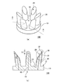
- FIG. 1 It is a schematic diagram which shows the outline of an example of the biomedical electrode of this embodiment.
- (A) is a perspective view
- (b) is a sectional view taken along the line AA of (a).
- (A) is a perspective view
- (b) is a sectional view taken along the line AA of (a).
- the front, rear, left, right, up, and down directions are defined and described. However, this is provided for convenience in order to briefly describe the relative relationship of the components. Therefore, it does not limit the direction in which the product embodying the present invention is manufactured or used.
- the same reference numerals are given to the same components, and the description thereof will be omitted as appropriate.
- the figure is a schematic view and does not match the actual dimensional ratio.
- the term “substantially” indicates that it includes a range in which manufacturing tolerances, variations, and the like are taken into consideration, unless otherwise specified. Unless otherwise specified, “to” includes the upper limit value and the lower limit value.
- the biological electrode of the present embodiment will be outlined.
- the biomedical electrode includes a plate-shaped support portion, an elastic columnar portion provided on one surface of the plate-shaped support portion, a conductive resin layer formed so as to cover the tip of the elastic columnar portion, a conductive resin layer, and an electrically conductive resin layer. Electrically connected to each other and arranged inside the elastic columnar portion from the distal end side toward the proximal end side.
- the present inventor has obtained the following findings.
- a configuration has been studied in which the conduction of the columnar portion of the biomedical electrode is realized only by the conductive resin layer.
- the conductive resin layer may be disconnected due to the deformation of the columnar portion, or the internal resistance of the conductive resin layer may be changed due to the expansion and contraction deformation of the columnar portion, It is estimated that noise may occur.
- the conductive wire is disposed inside the columnar portion from the tip end side toward the base end side and can be electrically connected to the conductive resin layer on the tip end side.
- the columnar portions of the biomedical electrode When the plurality of columnar portions of the biomedical electrode come into contact with the measurement target, the columnar portions elastically deform so as to spread outward. That is, the outside of the columnar portion is deformed in the shrinking direction, and the inside is deformed in the pulling direction. At this time, the internal deformation and deformation strain are relatively small as compared with the deformation on the surface of the columnar portion. Therefore, as a result of the study, the conductive wire arranged inside the columnar portion is less likely to be broken as compared with the conductive resin layer formed on the surface of the columnar portion, and the fluctuation of the internal resistance due to the deformation is also reduced. I found out.
- the biomedical electrode of the present embodiment that employs both the conductive resin layer and the conductive wire, compared to the configuration that employs the conductive resin layer alone, because it is possible to suppress the disconnection and noise generation due to the deformation of the columnar portion, It has been found that the measurement stability can be improved.
- the tip of the columnar portion of the biomedical electrode is configured to be hard, and therefore an iron ball is used as the tip. It is expected that the subject will feel pain and discomfort, as in the case of the provision.
- the conductive resin layer formed at the tip of the columnar portion of the biomedical electrode is superior in flexibility as compared with the metal portion made of metal, and is configured to be highly conformable to the measurement target. Therefore, the biomedical electrode of the present embodiment can realize a structure having excellent mounting stability and measurement stability.
- the biomedical electrode of the present embodiment can detect potential fluctuations from the living body such as brain waves, heartbeats, muscle activities, and nervous system activities.
- the biomedical electrode can further include a connector, an electronic component, and the like to form a biometric sensor that can be connected to an external device. This biometric sensor is wearable. By analyzing a bioelectric potential such as an electroencephalogram detected by a biosensor, a biosignal measurement system can be constructed for various purposes.
- FIG. 1A and 1B are schematic views showing an outline of the biomedical electrode 100 of the present embodiment, FIG. 1A is a perspective view, and FIG. 1B is a sectional view taken along the line AA of FIG.
- an example of the biomedical electrode 100 includes a plate-shaped support portion 10, a columnar portion 20 (elastic columnar portion), and a conductive resin layer 30.
- the plate-shaped support portion 10 is made of an insulating elastic member, and may have one or more columnar portions 20 on one surface 12 thereof.
- the columnar portion 20 is composed of an insulating elastic member.
- the conductive resin layer 30 is made of a conductive elastic member, and may be formed so as to cover at least the surface of the tip 22 (a part of the tip portion 26) of the columnar portion 20.
- the conductive wire 60 is arranged inside the columnar portion 20 so as to be electrically connected to the conductive resin layer 30.
- the bioelectric signal detected by the columnar portion 20 is passed through the conductive resin layer 30 and the conductive wire 60, and the connector provided on the plate-shaped support portion 10 is provided. (External connection 110). Then, the bioelectric signal detected by the biomedical electrode 100 is transmitted to the outside via the connector.
- a known wire can be used as the conductive wire 60, but the conductive wire 60 can be made of, for example, conductive fiber.
- the conductive fiber one or more selected from the group consisting of metal fiber, metal-coated fiber, carbon fiber, conductive polymer fiber, conductive polymer-coated fiber, and conductive paste-coated fiber can be used. These may be used alone or in combination of two or more.
- the metal material of the metal fiber, the metal coated fiber is not limited as long as it has conductivity, copper, silver, gold, nickel, tin, lead, zinc, bismuth, antimony, stainless steel, aluminum, and these Examples include alloys. These may be used alone or in combination of two or more. Among these, silver can be used from the viewpoint of conductivity. Moreover, it is preferable that the metal material does not include a metal such as chromium that exerts a load on the environment.
- the fiber material of the metal-coated fiber, the conductive polymer-coated fiber, and the conductive paste-coated fiber is not particularly limited, and may be synthetic fiber, semi-synthetic fiber, or natural fiber. Among these, polyester, nylon, polyurethane, silk, cotton and the like are preferably used. These may be used alone or in combination of two or more.
- Examples of the carbon fibers include PAN-based carbon fibers and pitch-based carbon fibers.
- the conductive polymer material of the conductive polymer fiber and the conductive polymer coated fiber for example, polythiophene, polypyrrole, polyaniline, polyacetylene, polyphenylene vinylene, polynaphthalene, and a mixture of a conductive polymer and a binder resin such as derivatives thereof, Alternatively, an aqueous solution of a conductive polymer such as PEDOT-PSS ((3,4-ethylenedioxythiophene) -poly (styrenesulfonic acid)) is used.
- PEDOT-PSS ((3,4-ethylenedioxythiophene) -poly (styrenesulfonic acid)
- the resin material contained in the conductive paste-coated fiber conductive paste is not particularly limited, but preferably has elasticity, for example, silicone rubber, urethane rubber, fluorine rubber, nitrile rubber, acrylic rubber, styrene rubber, chloroprene rubber, and ethylene. It may contain one or more selected from the group consisting of propylene rubber. These may be used alone or in combination of two or more.
- the conductive filler contained in the conductive paste of the conductive paste coated fiber is not particularly limited, may be used known conductive material, metal particles, metal fibers, metal coated fibers, carbon black, acetylene black, graphite, carbon It may include one or more selected from the group consisting of fibers, carbon nanotubes, conductive polymers, conductive polymer coated fibers and metal nanowires.
- the metal constituting the conductive filler is not particularly limited, but for example, at least one of copper, silver, gold, nickel, tin, lead, zinc, bismuth, antimony, or an alloy thereof, or these Two or more of these can be included.
- silver or copper is preferable because of its high conductivity and high availability.
- the conductive wire 60 may be composed of a twisted yarn in which a plurality of linear conductive fibers are twisted together. Thereby, the breakage of the conductive wire 60 at the time of deformation can be suppressed.
- the coating on the conductive fibers means not only covering the outer surface of the fiber material, but in the case of a twisted yarn in which single fibers are twisted together, a metal or conductive polymer is present in the fiber gap in the twisted yarn. Or a single fiber that is impregnated with a conductive paste and that constitutes a twisted yarn is covered by each.
- the tensile breaking elongation of the conductive wire 60 is, for example, 1% to 50%, preferably 1.5% to 45%. By setting it within such a numerical range, it is possible to suppress excessive deformation of the columnar portion 20 while suppressing breakage during deformation.
- the conductive wire 60 may adopt various arrangement structures as long as it is a mode in which the inside of the columnar portion 20 is electrically connected.
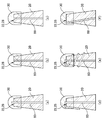
- An example of the arrangement structure of the conductive wire 60 is shown in FIGS.
- the tip of the conductive wire 60 protrudes with respect to the tip 22 of the columnar portion 20 or the inclined surface 28 (FIGS. 3A, 3D, and 3E), and the structure is substantially on the same plane (FIG. 3). Either (b)) or the buried structure (FIG. 3C) may be used. From the viewpoint of connection stability with the conductive resin layer 30, a protruding structure can be adopted.
- the protruding portion at the tip of the conductive wire 60 is partially or entirely covered with the conductive resin layer 30.
- the ejection structure at the tip of the conductive wire 60 is not folded (FIG. 3A), folded (FIG. 3D), or wound around the surface of the tip of the columnar portion 20 (FIG. 3E). You can Further, the conductive wire 60 may be inclined with respect to the central axis of the columnar portion 20 without passing through the central axis (FIG. 3 (f)).
- the other end of the conductive wire 60 on the side opposite to the tip may have any configuration as long as it can electrically conduct to a connector connected to the other surface 14 of the plate-shaped support portion 10.
- the other end of the conductive wire 60 may pass through the base end portion 24 of the columnar portion 20 and further extend to the one surface 12, the side surface, or the other surface 14 side of the plate-shaped support portion 10.
- the other end of the conductive wire 60 may be electrically connected to the connector via the conductive resin layer 30 provided on the other surface 14.
- the conductive resin layer 30 may be configured to cover at least the surface of the tip 22 of the columnar portion 20, and cover the tip 22 of the columnar portion 20 to the tip portion 26 and the tip 22 to the middle of the base portion 24. May be configured as. That is, it may be configured so as not to cover the entire surface of the columnar portion 20.
- the conductive resin layer 30 may be configured to cover the one surface 12 or the other surface 14 of the plate-shaped support portion 10 separately from the portion that covers the tip 22.
- the conductive resin layer 30 is, for example, 8/10 L or less, preferably 8/10 L or less, from the tip 22 of the column 20 when the entire length of the column 20 (distance from the tip 22 to the base 24) is L. It may be formed in a region of 7/10 L or less, more preferably 6/10 L or less. Thereby, the cost can be reduced.
- the conductive resin layer 30 is, for example, 1/10 L or more, preferably 2/10 L or more, and more preferably 3/10 L from the tip 22 of the columnar section 20 when the entire length of the columnar section 20 is L. It may be formed in the above region. Thereby, the connection stability with the conductive wire 60 can be improved. Further, the contact resistance can be reduced by forming the conductive resin layer 30 having a certain area at the tip of the columnar portion 20.
- the top view shape of the plate-shaped support portion 10 may be, for example, a substantially circular shape such as an ellipse or a perfect circle, or a substantially polygonal shape such as a square, a rectangle, a pentagon, or a hexagon. The corners of the polygon may be rounded.
- the top view means observing from the top surface direction when viewed from the tip 22 of the columnar portion 20 toward the plate-shaped support portion 10.
- the one surface 12 of the plate-shaped support portion 10 may be configured as a flat surface, but may have a curved surface partially or entirely.
- the one surface 12 may be a surface that passes at least three contact points where the side surface of the columnar portion 20 and the plate-shaped support portion 10 are in contact with each other. Further, there may be no interface between the plate-shaped support portion 10 and the columnar portion 20, and the interface may be seamless.
- the other surface 14 of the plate-shaped support portion 10 may have a structure connectable to a connector.
- an electrode that can be electrically connected to the connector may be embedded in the other surface 14 opposite to the one surface 12 in a partially exposed state.
- at least a part or the whole of the other surface 14 may be covered with the conductive elastic member.
- the side surface of the plate-shaped support portion 10 may not be covered with the conductive elastic member.
- the plate-shaped support portion 10 may be formed integrally with the columnar portion 20. That is, the plate-shaped support portion 10 may be integrally formed of the same resin material as the columnar portion 20. For example, by molding a curable elastomer composition such as a silicone rubber-based curable composition described below, a molded body in which the plate-shaped support portion 10 and the plurality of columnar portions 20 are seamlessly joined is obtained. This makes it possible to realize an elastic molded body having excellent flexibility and strength.
- a curable elastomer composition such as a silicone rubber-based curable composition described below
- Each of the plate-shaped support portion 10 and the columnar portion 20 may be made of an insulating silicone rubber (rubber molded body) containing a silicone rubber without containing a conductive filler as one of the insulating elastic members.
- One or more of the columnar portions 20 may be provided so as to project from the one surface 12 of the plate-shaped support portion 10.
- the top view shape of the columnar portion 20 may be a substantially circular shape such as an ellipse or a perfect circle, or a substantially polygonal shape such as a square, a rectangle, a pentagon, or a hexagon.
- the plurality of columnar portions 20 be arranged so as to surround the central portion 50 of the one surface 12 of the plate-shaped support portion 10.
- the plurality of columnar portions 20 are arranged along the outer peripheral edge of the plate-shaped support portion 10. This makes it possible to improve the ability of the columnar section 20 to follow the living body.
- the central portion 50 may be a region including the position of the center of gravity of the one surface 12 when viewed from the direction of the normal to the one surface 12. Further, when the minimum distance from the center of gravity of the one surface 12 to the peripheral edge of the one surface 12 is Dmin, the center portion 50 may be within a range of 2/10 Dmin or less, preferably 1/10 Dmin or less from the center of gravity position.
- the plurality of columnar portions 20 may be arranged on the one surface 12 so as to be substantially circular or elliptical. Such columnar portions 20 may be arranged around the central portion 50 so as to form one or more concentric circles. As a result, when contacting the measurement target, the tip end portion 26 of the columnar portion 20 spreads out substantially evenly in the radial direction, so that measurement stability can be improved.
- the central portion 50 of the plate-shaped support portion 10 may be a portion positioned approximately equidistant from the tips 22 of the plurality of columnar portions 20 existing on the same circumference.
- the columnar portion 20 may have a structure in which the center of the columnar portion 20 is eccentric with respect to the direction perpendicular to the one surface 12 of the plate-shaped support portion 10. From the viewpoint of manufacturing stability, it is preferable that the central axis of the columnar portion 20 having an eccentric structure be inclined outward from the central portion 50 of the plate-shaped support portion 10.
- the inclination of the central axis of the columnar section 20 means that the columnar section 20 has a cross-sectional view that passes through the central section 50 and the central section of the columnar section 20 from the inner side to the outer side of each columnar section 20 with the central section 50 as a reference.
- the outside angle (acute angle) formed by the central axis and the one surface 12 (surface) of the plate-shaped support portion 10 is meant.
- the inclination of the central axis of the columnar portion 20 is, for example, 45 to 90 degrees, preferably 50 to 88 degrees, and more preferably 60 to 85 degrees. By setting it within such a numerical range, the mold releasability from the mold can be enhanced.
- the tip portions 26 of the plurality of columnar portions 20 are in a direction passing from the inside to the outside of each columnar portion 20, for example, the columnar portions outside the inner side in a cross-sectional view in the radial direction. It is possible to have an inclined surface 28 configured such that the height of 20 is increased.
- the inclined surface 28 of each columnar portion 20 may be configured to face the central portion 50 of the plate-shaped support portion 10. Since the inclined surface 28 can follow the measurement surface of the measurement object when the columnar portion 20 contacts the measurement object, variation in the contact area can be suppressed.
- the columnar portion 20 having the tip portion 26 may be formed in a substantially truncated cone shape or a substantially truncated pyramid shape. Among them, the substantially truncated cone shape is preferable from the viewpoint of measurement stability.
- the frustum-shaped columnar portion 20 is configured to have a smaller diameter from the connecting portion (base end portion 24) side of the plate-shaped support portion 10 toward the distal end 22 side. Therefore, the manufacturing stability in the die molding can be improved. Further, when viewed in the pushing direction, the inner side surface of the columnar section 20 has a tapered shape that widens from the inner side to the outer side, so that the variation in deformation of the columnar section 20 can be further suppressed.
- the top view shape of the inclined surface 28 may be, for example, a substantially elliptical shape.
- This substantially elliptical shape has a major axis in the radial direction of the substantially circumference in which the columnar portion 20 is arranged. It is possible to improve the followability to the measurement surface.
- the inclination angle ⁇ of the inclined surface 28 means the angle formed by the outer side surface of the columnar portion 20 and the inclined surface 28 in a cross-sectional view passing from the inside to the outside of each columnar portion 20. To do.
- the inclination angle ⁇ of the inclined surface 28 is, for example, 10 to 89 degrees, preferably 15 degrees to 80 degrees, more preferably 20 degrees to 60 degrees, and further preferably 25 degrees to 50 degrees.
- the columnar portion 20 may not have the inclined surface 28.
- the columnar portion 20 that does not have the inclined surface 28 may be configured in a substantially columnar shape, a substantially prismatic shape, a substantially conical shape, a substantially pyramidal shape, a substantially truncated cone shape, or a substantially truncated pyramid shape.
- a structure having a tapered shape such as a cone shape or a truncated cone shape is preferable from the viewpoint of manufacturing stability, and a substantially truncated cone shape is preferable from the viewpoint of measurement stability.
- the frustum-shaped columnar portion 20 is configured to have a smaller diameter from the connection portion (base end portion 24) side of the plate-shaped support portion 10 toward the tip 22 side.
- the top view shape of the tip 22 may be, for example, a substantially circular shape or a substantially polygonal shape.
- the columnar portion length from the base end portion 24 to the tip 22 connected to the plate-shaped support portion 10 is larger than the columnar portion width at the base end portion 24.
- the conductive resin layer 30 is made of conductive silicone rubber containing a conductive filler and silicone rubber as one of the conductive elastic members.
- a conductive solution obtained by adding a conductive filler to an insulating silicone rubber-based curable composition containing no conductive filler described below is applied to the above-mentioned molded body.
- the conductive resin layer 30 can be formed.
- the adhesion of the conductive resin layer 30 can be improved.
- a known conductive material may be used, but metal particles, silver / silver chloride particles, metal fibers, metal coated fibers, carbon black, acetylene black, graphite, carbon fibers, carbon nanotubes, conductive polymers , One or more selected from the group consisting of conductive polymer-coated fibers and metal nanowires.
- the metal constituting the conductive filler is not particularly limited, but is, for example, at least one of copper, silver, gold, nickel, tin, lead, zinc, bismuth, antimony, silver / silver chloride, or an alloy thereof. Alternatively, two or more of these may be included. Among these, silver or copper is preferable because of its high conductivity and high availability.
- the lower limit of the content of the conductive filler is, for example, 30% by mass or more, preferably 35% by mass or more, and more preferably 40% by mass or more with respect to 100% by mass of the silicone rubber in the conductive resin layer 30. is there. Thereby, even in the case of a thin film, the transmissibility of bioelectric signals can be improved.
- the upper limit of the content of the conductive filler is, for example, 90 mass% or less, preferably 85 mass% or less, and more preferably 80 mass% with respect to 100 mass% of the silicone rubber in the conductive resin layer 30. It is below. Thereby, the durability of the conductive resin layer 30 against the deformation of the columnar portion 20 can be improved.
- the lower limit of the film thickness of the conductive resin layer 30 is, for example, 5 ⁇ m or more, preferably 8 ⁇ m or more, more preferably 10 ⁇ m or more. This makes it possible to improve durability during repeated use.
- the upper limit of the film thickness of the conductive resin layer 30 is, for example, 200 ⁇ m or less, preferably 150 ⁇ m or less, more preferably 100 ⁇ m or less, and further preferably 50 ⁇ m or less. This makes it possible to maintain the deformability of the columnar section 20. In the cross-sectional view of the columnar section 20, it is preferable that the film thickness of at least a part of the conductive resin layer 30 on the tip 22 or the side surface of the columnar section 20 is within the above numerical range.
- the film thickness D1 on the surface of the tip end 22 of the columnar part 20 may be configured to be thicker than the film thickness of the conductive resin layer 30 on the base end part 24 side.
- a part of the columnar portion 20 on the side of the tip 22 may be dipped (immersion applied) in a paste-like conductive solution. It is preferable that the thick film is provided on the entire tip end portion of the columnar portion 20 in the circumferential direction. As a result, peeling at the tip of the conductive resin layer 30 can be suppressed, and damage such as disconnection of the columnar part 20 can be suppressed. Therefore, the durability of the biomedical electrode 100 can be improved.
- the silicone rubber-based curable composition will be described.
- the silicone rubber can be composed of a cured product of a silicone rubber-based curable composition.
- the curing step of the silicone rubber-based curable resin composition for example, after heating at 100 ° C. to 250 ° C. for 1 minute to 30 minutes (primary curing), post-baking at 200 ° C. for 1 hour to 4 hours (secondary curing) Is done by doing.
- the silicone rubber-based curable composition according to this embodiment may include a vinyl group-containing organopolysiloxane (A).
- the vinyl group-containing organopolysiloxane (A) is a polymer that is the main component of the silicone rubber-based curable composition of this embodiment.
- the vinyl group-containing organopolysiloxane (A) may include a vinyl group-containing linear organopolysiloxane (A1) having a linear structure.
- the vinyl group-containing linear organopolysiloxane (A1) has a linear structure and contains a vinyl group, and the vinyl group serves as a crosslinking point during curing.
- the vinyl group content of the vinyl group-containing linear organopolysiloxane (A1) is not particularly limited, but for example, it is preferable that the vinyl group-containing linear organopolysiloxane (A1) has two or more vinyl groups in the molecule and is 15 mol% or less. More preferably 0.01 to 12 mol%. As a result, the amount of vinyl groups in the vinyl group-containing linear organopolysiloxane (A1) is optimized, and it is possible to reliably form a network with each component described below. In the present embodiment, “to” means to include numerical values at both ends thereof.
- the vinyl group content is the mol% of the vinyl group-containing siloxane unit when all the units constituting the vinyl group-containing linear organopolysiloxane (A1) are 100 mol%. .. However, it is considered that there is one vinyl group for one vinyl group-containing siloxane unit.
- the degree of polymerization of the vinyl group-containing linear organopolysiloxane (A1) is not particularly limited, but is, for example, preferably about 1000 to 10000, more preferably about 2000 to 5000.
- the degree of polymerization can be determined, for example, as a polystyrene-equivalent number average degree of polymerization (or number average molecular weight) in GPC (gel permeation chromatography) using chloroform as a developing solvent.
- the specific gravity of the vinyl group-containing linear organopolysiloxane (A1) is not particularly limited, but is preferably in the range of about 0.9 to 1.1.
- the resulting silicone rubber has heat resistance, flame retardancy, chemical stability, etc. Can be improved.
- the vinyl group-containing linear organopolysiloxane (A1) is particularly preferably one having a structure represented by the following formula (1).
- R 1 is a substituted or unsubstituted alkyl group having 1 to 10 carbon atoms, an alkenyl group, an aryl group, or a hydrocarbon group obtained by combining these.
- alkyl group having 1 to 10 carbon atoms include a methyl group, an ethyl group and a propyl group, and among them, a methyl group is preferable.
- alkenyl group having 1 to 10 carbon atoms include a vinyl group, an allyl group and a butenyl group, and among them, a vinyl group is preferable.
- the aryl group having 1 to 10 carbon atoms include phenyl group and the like.
- R 2 is a substituted or unsubstituted alkyl group having 1 to 10 carbon atoms, an alkenyl group, an aryl group, or a hydrocarbon group obtained by combining these.
- alkyl group having 1 to 10 carbon atoms include a methyl group, an ethyl group and a propyl group, and among them, a methyl group is preferable.
- alkenyl group having 1 to 10 carbon atoms include vinyl group, allyl group and butenyl group.
- the aryl group having 1 to 10 carbon atoms include phenyl group.
- R 3 is a substituted or unsubstituted alkyl group having 1 to 8 carbon atoms, an aryl group, or a hydrocarbon group obtained by combining these.
- alkyl group having 1 to 8 carbon atoms include a methyl group, an ethyl group and a propyl group, and among them, a methyl group is preferable.
- aryl group having 1 to 8 carbon atoms include phenyl group.
- examples of the substituent of R 1 and R 2 in the formula (1) include a methyl group and a vinyl group
- examples of the substituent of R 3 include a methyl group and the like.
- a plurality of R 1's are independent of each other and may be different from each other or the same. Further, the same applies to R 2 and R 3 .
- m and n are the numbers of repeating units constituting the vinyl group-containing linear organopolysiloxane (A1) represented by the formula (1), m is an integer of 0 to 2000, and n is 1000 to 10000. Is an integer. m is preferably 0 to 1000, and n is preferably 2000 to 5000.
- the specific structure of the vinyl group-containing linear organopolysiloxane (A1) represented by the formula (1) includes, for example, one represented by the following formula (1-1).
- R 1 and R 2 are each independently a methyl group or a vinyl group, and at least one is a vinyl group.
- the vinyl group-containing linear organopolysiloxane (A1) the first vinyl group-containing vinyl group containing two or more vinyl groups in the molecule and 0.4 mol% or less
- a straight-chain organopolysiloxane (A1-1) and a second vinyl-group-containing straight-chain organopolysiloxane (A1-2) having a vinyl group content of 0.5 to 15 mol%.
- a first vinyl group-containing linear organopolysiloxane (A1-1) having a general vinyl group content and a second vinyl group-containing straight chain having a high vinyl group content By combining with the chain organopolysiloxane (A1-2), the vinyl groups can be unevenly distributed, and the crosslink density of the silicone rubber can be more effectively formed. As a result, the tear strength of the silicone rubber can be increased more effectively.
- the vinyl group-containing linear organopolysiloxane (A1) for example, a unit in which R 1 is a vinyl group and / or a unit in which R 2 is a vinyl group in the above formula (1-1) is used.
- the first vinyl group-containing linear organopolysiloxane (A1-1) preferably has a vinyl group content of 0.01 to 0.2 mol%.
- the second vinyl group-containing linear organopolysiloxane (A1-2) preferably has a vinyl group content of 0.8 to 12 mol%.
- the ratio of (A1-2) to (A1-2) is not particularly limited, but for example, the weight ratio of (A1-1) :( A1-2) is preferably 50:50 to 95: 5, and 80:20 to 90 :. More preferably, it is 10.
- Each of the first and second vinyl group-containing linear organopolysiloxanes (A1-1) and (A1-2) may be used alone or in combination of two or more. Good.
- the vinyl group-containing organopolysiloxane (A) may include a vinyl group-containing branched organopolysiloxane (A2) having a branched structure.
- the silicone rubber-based curable composition of the present embodiment can include an organohydrogenpolysiloxane (B).
- the organohydrogenpolysiloxane (B) is classified into a linear organohydrogenpolysiloxane having a linear structure (B1) and a branched organohydrogenpolysiloxane having a branched structure (B2). Either or both may be included.
- the straight-chain organohydrogenpolysiloxane (B1) has a straight-chain structure and also has a structure in which hydrogen is directly bonded to Si ( ⁇ Si—H).
- it is a polymer that crosslinks these components by hydrosilylation reaction with vinyl groups contained in the components blended in the silicone rubber-based curable composition.
- the molecular weight of the linear organohydrogenpolysiloxane (B1) is not particularly limited, but for example, the weight average molecular weight is preferably 20000 or less, more preferably 1000 or more and 10000 or less.
- the weight average molecular weight of the linear organohydrogenpolysiloxane (B1) can be measured, for example, by polystyrene conversion in GPC (gel permeation chromatography) using chloroform as a developing solvent.
- the linear organohydrogenpolysiloxane (B1) usually preferably has no vinyl group. This makes it possible to properly prevent the crosslinking reaction from proceeding in the molecule of the linear organohydrogenpolysiloxane (B1).
- linear organohydrogenpolysiloxane (B1) as described above for example, one having a structure represented by the following formula (2) is preferably used.
- R 4 is a substituted or unsubstituted alkyl group having 1 to 10 carbon atoms, an alkenyl group, an aryl group, a hydrocarbon group in which these are combined, or a hydride group.
- alkyl group having 1 to 10 carbon atoms include a methyl group, an ethyl group and a propyl group, and among them, a methyl group is preferable.
- alkenyl group having 1 to 10 carbon atoms include vinyl group, allyl group, butenyl group and the like.
- the aryl group having 1 to 10 carbon atoms include phenyl group.
- R 5 is a substituted or unsubstituted alkyl group having 1 to 10 carbon atoms, an alkenyl group, an aryl group, a hydrocarbon group obtained by combining these, or a hydride group.
- alkyl group having 1 to 10 carbon atoms include a methyl group, an ethyl group and a propyl group, and among them, a methyl group is preferable.
- alkenyl group having 1 to 10 carbon atoms include vinyl group, allyl group, butenyl group and the like.
- the aryl group having 1 to 10 carbon atoms include phenyl group.
- the plurality of R 4's are independent of each other and may be different from each other or the same. The same applies to R 5 . However, at least two or more of the plurality of R 4 and R 5 are hydrido groups.
- R 6 is a substituted or unsubstituted alkyl group having 1 to 8 carbon atoms, an aryl group, or a hydrocarbon group obtained by combining these.
- alkyl group having 1 to 8 carbon atoms include a methyl group, an ethyl group and a propyl group, and among them, a methyl group is preferable.
- aryl group having 1 to 8 carbon atoms include phenyl group.
- a plurality of R 6's are independent of each other and may be different from each other or the same.
- R 4 , R 5 and R 6 in the formula (2) for example, a methyl group, a vinyl group and the like can be mentioned, and a methyl group is preferable from the viewpoint of preventing intramolecular crosslinking reaction.
- m and n are the numbers of repeating units constituting the linear organohydrogenpolysiloxane (B1) represented by the formula (2), m is an integer of 2 to 150, and n is an integer of 2 to 150. Is. Preferably, m is an integer of 2-100 and n is an integer of 2-100.
- the linear organohydrogenpolysiloxane (B1) may be used alone or in combination of two or more.
- the branched organohydrogenpolysiloxane (B2) is a component that has a branched structure and thus forms a region having a high crosslink density, which greatly contributes to the formation of a sparse and dense structure of the crosslink density in the silicone rubber system. Further, like the above-mentioned linear organohydrogenpolysiloxane (B1), it has a structure in which hydrogen is directly bonded to Si ( ⁇ Si—H), and in addition to the vinyl group of the vinyl group-containing organopolysiloxane (A), silicone It is a polymer that crosslinks these components by a hydrosilylation reaction with the vinyl groups of the components blended in the rubber-based curable composition.
- the specific gravity of the branched organohydrogenpolysiloxane (B2) is in the range of 0.9 to 0.95.
- the branched organohydrogenpolysiloxane (B2) usually does not have a vinyl group. This makes it possible to properly prevent the crosslinking reaction from proceeding in the molecule of the branched organohydrogenpolysiloxane (B2).
- branched organohydrogenpolysiloxane (B2) those represented by the following average composition formula (c) are preferable.
- R 7 is a monovalent organic group, a is an integer in the range of 1 to 3, m is the number of H a (R 7 ) 3-a SiO 1/2 units, and n is SiO 4 / It is a number of 2 units)
- R 7 is a monovalent organic group, preferably a substituted or unsubstituted alkyl group having 1 to 10 carbon atoms, an aryl group, or a hydrocarbon group in which these are combined.
- alkyl group having 1 to 10 carbon atoms include a methyl group, an ethyl group and a propyl group, and among them, a methyl group is preferable.
- aryl group having 1 to 10 carbon atoms include phenyl group.
- a is the number of hydride groups (hydrogen atoms directly bonded to Si), and is an integer in the range of 1 to 3, preferably 1.
- m is the number of H a (R 7 ) 3-a SiO 1/2 units
- n is the number of SiO 4/2 units.
- the branched organohydrogenpolysiloxane (B2) has a branched structure.
- the linear organohydrogenpolysiloxane (B1) and the branched organohydrogenpolysiloxane (B2) are different in that their structures are linear or branched, and when the number of Si is 1,
- the number of alkyl groups R (R / Si) to be bonded is 1.8 to 2.1 for the straight chain organohydrogenpolysiloxane (B1) and 0.8 to 1 for the branched organohydrogenpolysiloxane (B2). It will be in the range of 0.7.
- the branched organohydrogenpolysiloxane (B2) has a branched structure, for example, the residue amount when heated to 1000 ° C. at a heating rate of 10 ° C./min in a nitrogen atmosphere has a residue amount of 5% or more. Becomes On the other hand, since the linear organohydrogenpolysiloxane (B1) is linear, the amount of residue after heating under the above conditions becomes almost zero.
- branched organohydrogenpolysiloxane (B2) include those having a structure represented by the following formula (3).
- R 7 is a substituted or unsubstituted alkyl group having 1 to 8 carbon atoms, an aryl group, a hydrocarbon group in which these are combined, or a hydrogen atom.
- alkyl group having 1 to 8 carbon atoms include a methyl group, an ethyl group and a propyl group, and among them, a methyl group is preferable.
- aryl group having 1 to 8 carbon atoms include phenyl group.
- the substituent of R 7 include a methyl group and the like.
- a plurality of R 7's are independent of each other and may be different from each other or the same.
- —O—Si ⁇ represents that Si has a branched structure that spreads in three dimensions.
- the branched organohydrogenpolysiloxane (B2) may be used alone or in combination of two or more.
- the amount of hydrogen atoms (hydrido groups) directly bonded to Si is not particularly limited.
- the linear organohydrogenpolysiloxane (B1) and the branched organohydrogenpolysiloxane are added to 1 mol of vinyl groups in the vinyl group-containing linear organopolysiloxane (A1).
- the total amount of hydrido groups of the siloxane (B2) is preferably 0.5 to 5 mol, more preferably 1 to 3.5 mol.
- the silicone rubber-based curable composition according to the present embodiment may contain silica particles (C), if necessary. Thereby, the hardness and mechanical strength of the elastomer can be improved.
- the silica particles (C) are not particularly limited, but for example, fumed silica, calcined silica, precipitated silica and the like are used. These may be used alone or in combination of two or more.
- the silica particles (C) preferably have a specific surface area according to the BET method of, for example, 50 to 400 m 2 / g, and more preferably 100 to 400 m 2 / g.
- the average primary particle size of the silica particles (C) is preferably, for example, 1 to 100 nm, more preferably about 5 to 20 nm.
- silica particles (C) having such a specific surface area and an average particle diameter within the above ranges, it is possible to improve the hardness and mechanical strength of the silicone rubber to be formed, especially the tensile strength.
- the silicone rubber-based curable composition of this embodiment may include a silane coupling agent (D).
- the silane coupling agent (D) can have a hydrolyzable group.
- the hydrolyzable group is hydrolyzed by water to form a hydroxyl group, and this hydroxyl group undergoes a dehydration condensation reaction with the hydroxyl group on the surface of the silica particle (C), whereby the surface of the silica particle (C) can be modified.
- the silane coupling agent (D) may include a silane coupling agent having a hydrophobic group.
- this hydrophobic group is imparted to the surface of the silica particles (C), so that the cohesive force of the silica particles (C) decreases in the silicone rubber-based curable composition and further in the silicone rubber (hydrogen due to silanol groups). It is presumed that cohesion due to bonding is reduced), and as a result, the dispersibility of the silica particles (C) in the silicone rubber-based curable composition is improved. Thereby, the interface between the silica particles (C) and the rubber matrix increases, and the reinforcing effect of the silica particles (C) increases.
- the slipperiness of the silica particles (C) in the matrix is improved when the rubber is deformed into the matrix.
- the mechanical strength (for example, tensile strength and tear strength) of the silicone rubber by the silica particles (C) is improved by the improvement of the dispersibility and the slipperiness of the silica particles (C).
- the silane coupling agent (D) may include a silane coupling agent having a vinyl group.
- a vinyl group is introduced on the surface of the silica particles (C). Therefore, when the silicone rubber-based curable composition is cured, that is, the vinyl group contained in the vinyl group-containing organopolysiloxane (A) and the hydride group contained in the organohydrogenpolysiloxane (B) undergo a hydrosilylation reaction. In forming the network (crosslinked structure) by these, the vinyl group contained in the silica particles (C) also participates in the hydrosilylation reaction with the hydrido group contained in the organohydrogenpolysiloxane (B), and therefore, in the network. The silica particles (C) will also be taken into. As a result, it is possible to reduce the hardness and the modulus of the formed silicone rubber.
- silane coupling agent (D) a silane coupling agent having a hydrophobic group and a silane coupling agent having a vinyl group can be used in combination.
- silane coupling agent (D) examples include those represented by the following formula (4).
- n represents an integer of 1 to 3.
- Y represents a functional group selected from those having a hydrophobic group, a hydrophilic group or a vinyl group. When n is 1, it is a hydrophobic group, and when n is 2 or 3, at least one of them is It is a hydrophobic group.
- X represents a hydrolyzable group.
- the hydrophobic group is an alkyl group having 1 to 6 carbon atoms, an aryl group, or a hydrocarbon group in which these are combined, and examples thereof include a methyl group, an ethyl group, a propyl group, a phenyl group, and the like.
- a methyl group is preferred.
- hydrophilic group examples include a hydroxyl group, a sulfonic acid group, a carboxyl group, and a carbonyl group, and among them, a hydroxyl group is particularly preferable.
- the hydrophilic group may be contained as a functional group, but is preferably not contained from the viewpoint of imparting hydrophobicity to the silane coupling agent (D).
- examples of the hydrolyzable group include an alkoxy group such as a methoxy group and an ethoxy group, a chloro group, or a silazane group.
- the silazane group is preferable because it has high reactivity with the silica particles (C).
- those having a silazane group as a hydrolyzable group have two (Y n —Si—) structures in the above formula (4) due to their structural characteristics.
- silane coupling agent (D) represented by the above formula (4) are as follows.
- a silane coupling agent having a trimethylsilyl group containing at least one selected from the group consisting of hexamethyldisilazane, trimethylchlorosilane, trimethylmethoxysilane, and trimethylethoxysilane is preferable.
- vinyltriethoxysilane methacryloxypropyltriethoxysilane, methacryloxypropyltrimethoxysilane, methacryloxypropylmethyldiethoxysilane, methacryloxypropylmethyldimethoxysilane, vinyltriethoxysilane, vinyltrimethoxy
- Examples include silanes, alkoxysilanes such as vinylmethyldimethoxysilane; chlorosilanes such as vinyltrichlorosilane and vinylmethyldichlorosilane; and divinyltetramethyldisilazane.
- a silane coupling agent having a vinyl group-containing organosilyl group containing at least one selected from the group consisting of methyldimethoxysilane is preferable.
- silane coupling agent (D) contains two kinds of silane coupling agents having a trimethylsilyl group and silane coupling agents having a vinyl group-containing organosilyl group, hexamethyldisilazane as a hydrophobic group, As those having a vinyl group, it is preferable to include divinyltetramethyldisilazane.
- the ratio of (D1) and (D2) is not particularly limited, but, for example, The weight ratio of (D1) :( D2) is 1: 0.001 to 1: 0.35, preferably 1: 0.01 to 1: 0.20, and more preferably 1: 0.03 to 1: 0. .15.
- the weight ratio of (D1) :( D2) is 1: 0.001 to 1: 0.35, preferably 1: 0.01 to 1: 0.20, and more preferably 1: 0.03 to 1: 0. .15.
- the lower limit of the content of the silane coupling agent (D) is preferably 1% by mass or more based on 100 parts by weight of the total amount of the vinyl group-containing organopolysiloxane (A). It is more preferably at least mass% and even more preferably at least 5 mass%.
- the upper limit of the content of the silane coupling agent (D) is preferably 100% by mass or less, and 80% by mass or less, based on 100 parts by weight of the total amount of the vinyl group-containing organopolysiloxane (A). It is more preferable that the amount is 40% by mass or less.
- the content of the silane coupling agent (D) By setting the content of the silane coupling agent (D) to be the lower limit value or more, the adhesion between the columnar portion containing the elastomer and the conductive resin layer can be enhanced. Further, it can contribute to the improvement of the mechanical strength of the silicone rubber. Further, when the content of the silane coupling agent (D) is not more than the above upper limit value, the silicone rubber can have appropriate mechanical properties.
- the silicone rubber-based curable composition according to this embodiment may include platinum or a platinum compound (E). Platinum or a platinum compound (E) is a catalyst component that acts as a catalyst during curing. The amount of platinum or platinum compound (E) added is a catalytic amount.
- platinum or a platinum compound (E) known ones can be used, and examples thereof include platinum black, platinum supported on silica or carbon black, chloroplatinic acid or an alcohol solution of chloroplatinic acid, or chloroplatinic acid. Examples thereof include a complex salt of platinic acid and olefin, a complex salt of chloroplatinic acid and vinylsiloxane, and the like.
- the platinum or platinum compound (E) may be used alone or in combination of two or more.
- the content of platinum or the platinum compound (E) in the silicone rubber-based curable composition means a catalytic amount and can be set appropriately, but specifically, a vinyl group-containing organopolysiloxane.
- the amount of the platinum group metal is 0.01 to 1000 ppm in weight unit with respect to 100 parts by weight of the total amount of (A), silica particles (C), and silane coupling agent (D), and preferably 0.1.
- the amount is 1 to 500 ppm.
- the silicone rubber-based curable composition according to the present embodiment may contain water (F) in addition to the above components (A) to (E).
- Water (F) is a component that functions as a dispersion medium for dispersing each component contained in the silicone rubber-based curable composition and contributes to the reaction between the silica particles (C) and the silane coupling agent (D). . Therefore, the silica particles (C) and the silane coupling agent (D) can be more reliably connected to each other in the silicone rubber, and uniform properties can be exhibited as a whole.
- the silicone rubber-based curable composition of the present embodiment may further contain other components in addition to the components (A) to (F).
- other components for example, other than silica particles (C) such as diatomaceous earth, iron oxide, zinc oxide, titanium oxide, barium oxide, magnesium oxide, cerium oxide, calcium carbonate, magnesium carbonate, zinc carbonate, glass wool, mica, etc.
- additives include inorganic fillers, reaction inhibitors, dispersants, pigments, dyes, antistatic agents, antioxidants, flame retardants, and thermal conductivity improvers.
- the conductive solution according to the present embodiment contains the conductive filler and a solvent in addition to the silicone rubber-based curable composition containing no conductive filler.
- solvent various known solvents can be used, and for example, a high boiling point solvent can be included. These may be used alone or in combination of two or more.
- solvent examples include aliphatic hydrocarbons such as pentane, hexane, cyclohexane, heptane, methylcyclohexane, ethylcyclohexane, octane, decane, dodecane, tetradecane; benzene, toluene, ethylbenzene, xylene, trifluoromethylbenzene.
- aliphatic hydrocarbons such as pentane, hexane, cyclohexane, heptane, methylcyclohexane, ethylcyclohexane, octane, decane, dodecane, tetradecane
- benzene toluene
- ethylbenzene xylene
- trifluoromethylbenzene examples include aliphatic hydrocarbons such as pentane, hexane, cyclo
- Aromatic hydrocarbons such as benzotrifluoride; diethyl ether, diisopropyl ether, dibutyl ether, cyclopentyl methyl ether, cyclopentyl ethyl ether, ethylene glycol dimethyl ether, ethylene glycol diethyl ether, diethylene glycol dimethyl ether, 1,4-dioxane, 1,3 -Ethers such as dioxane and tetrahydrofuran; dichloromethane, chloroform, 1,1-dichloroethane, , 2-dichloroethane, 1,1,1-trichloroethane, 1,1,2-trichloroethane and other haloalkanes; N, N-dimethylformamide, N, N-dimethylacetamide and other carboxylic acid amides; dimethyl sulfoxide, diethyl sulfoxide Examples thereof include sulfoxides. These may be used alone or in combination of
- the conductive solution can have a viscosity suitable for various coating methods such as spray coating and dip coating.
- the lower limit of the content of the silica particles (C) contained in the conductive resin layer 30 is the silica particles (C) and the conductive particles.
- the total amount of the filler can be, for example, 1% by mass or more, preferably 3% by mass or more, and more preferably 5% by mass or more, with respect to 100% by mass. Thereby, the mechanical strength of the conductive resin layer 30 can be improved.
- the upper limit of the content of the silica particles (C) contained in the conductive resin layer 30 is, for example, 20% by mass or less based on 100% by mass of the total amount of the silica particles (C) and the conductive filler. %, Preferably 15% by mass or less, more preferably 10% by mass or less. This makes it possible to balance the conductivity of the conductive resin layer 30 with the mechanical strength and flexibility.
- An example of the method for manufacturing the biomedical electrode 100 according to the present embodiment may include the following steps. First, the silicone rubber-based curable composition is heat-pressed and molded using a mold to obtain a molded product having the plate-shaped support portion 10 and the columnar portion 20 (molding step).
- the conductive wire 60 is inserted into the columnar portion 20 (conductive wire insertion step).
- the conductive wire 60 can be passed through the inside of the columnar portion 20 using a needle. Mass production is possible by using a sewing machine.
- insert molding may be used in which, during the molding step, the silicone rubber-based curable composition is introduced into the molding space in which the conductive wire 60 is placed, and pressure molding is performed.
- the tip of the columnar part 20 of the obtained molded body is dip-coated with the above-mentioned conductive solution and dried by heating (tip covering step). Then, post cure (annealing step) is performed at a predetermined temperature and temperature condition.
- the biomedical electrode 100 can be manufactured.
- the inclined surface 28 may be formed by cutting the tip end portion 26 of the columnar portion 20 into a desired shape after the forming step and before the conductive wire inserting step. Alternatively, instead of cutting, the inclined surface 28 may be formed on the tip end portion 26 of the columnar portion 20 by die molding.
- the biomedical electrode 100 of the present embodiment can detect a bioelectric signal generated from a bioactivity of the brain, heart, muscles, nerves and the like. Since this biomedical electrode 100 has flexibility and is excellent in wearability on the scalp, it can be suitably used as an electrode for measuring brain waves.
- Electrodes for measuring brain waves using the biomedical electrode 100 are expected to be used for BMI (Brain Machine Interface).
- the biomedical electrode 100 can be used as a simple dry sensor that can be repeatedly used, rather than a wet sensor that requires the application of gel to the measurement portion.
- the biomedical electrode 100 can have flexibility that can reduce pain and discomfort of a subject (user) as compared with a metal pin type dry sensor with a spring.
- the biomedical electrode 100 can be mounted on a wearable device by miniaturization.
- FIG. 4 is a schematic diagram showing an outline of an example of the biosensor 200.
- the biometric sensor 200 of the present embodiment includes the biomedical electrode 100, and may further include an external connection unit 110 connected to the biomedical electrode 100.
- the external connection portion 110 may be detachably attached to the plate-shaped support portion 10 of the biomedical electrode 100, but may be fixed to the plate-shaped support portion 10.
- the external connection part 110 is stronger than silicone rubber from the viewpoint of durability and includes at least an external electrode part having conductivity.
- the external electrode portion is made of metal, for example.
- the external electrode unit can send the bioelectric signal detected by the biomedical electrode 100 to an external electronic component.
- the shape of the external electrode portion is not particularly limited, but a connector that can be connected to an electronic component or a wiring can be attached.
- the external connection unit 110 may be configured by a metal snap button, and may have a structure in which it is electrically connected to an external wiring or an electrode of the substrate by a contact pin.
- the biometric sensor 200 may further include an electronic component that can be electrically connected via the external connection unit 110.
- the electronic parts known parts can be used according to various uses, and examples thereof include an amplifier, an AD converter, an impedance, a CPU, a memory, a communication circuit, and a battery. One or more of these may be modularized on the circuit board. Thereby, the biometric sensor 200 can be utilized as a wearable device. Also, other sensors such as an acceleration sensor and a temperature sensor may be used together as the electronic component.
- the biosensor 200 includes one or more bioelectrodes 100.
- the biometric sensor 200 may be installed in a living body attachment jig such as a headgear or an arm band.
- the biological signal measuring system of this embodiment includes a biological sensor 200.
- the biological signal measuring system may be a system (measuring device) that displays, analyzes, or stores the data received from the biological sensor 200.
- An electrode for living body comprising: 2. 1. A biomedical electrode according to A biomedical electrode, wherein the conductive wire is composed of a conductive fiber. 3. 2. A biomedical electrode according to The biomedical electrode, wherein the conductive wire is composed of a twisted yarn in which a plurality of linear conductive fibers are twisted together. 4. 2. Or 3.
- 9. 8 A biomedical electrode according to The biomedical electrode, wherein the content of the conductive filler is 30% by mass or more and 90% by mass or less based on 100% by mass of the silicone rubber. 10. 8. Or 9.
- a biomedical electrode according to The conductive filler is selected from the group consisting of metal particles, metal fibers, metal coated fibers, carbon black, acetylene black, graphite, carbon fibers, carbon nanotubes, conductive polymers, conductive polymer coated fibers and metal nanowires.
- Silica particles (C) (C): Silica fine particles (particle size 7 nm, specific surface area 300 m 2 / g), "AEROSIL 300” manufactured by Nippon Aerosil Co., Ltd.
- D-1) Hexamethyldisilazane (HMDZ), manufactured by Gelest, "HEXAMETHYLDISILAZANE (SIH6110.1)”
- D-2) Divinyltetramethyldisilazane, manufactured by Gelest, "1,3-DIVINYLTETRAMETHYLDISILAZANE (SID4612.0)"
- a silicone rubber-based curable composition was prepared as follows. First, 90% of a mixture of vinyl group-containing organopolysiloxane (A), silane coupling agent (D) and water (F) was kneaded in advance at a ratio shown in Table 1 below, and then the silica particles ( C) was added and further kneaded to obtain a kneaded product (silicone rubber compound).
- the kneading after the addition of the silica particles (C) includes the first step of kneading for 1 hour under a nitrogen atmosphere at 60 to 90 ° C. for the coupling reaction and the removal of the by-product (ammonia).
- the second step of kneading for 2 hours at 160 to 180 ° C. under a reduced pressure atmosphere is carried out, followed by cooling, and the remaining 10% of vinyl group-containing organopolysiloxane (A) is added twice. Added separately and kneaded for 20 minutes. Then, organohydrogenpolysiloxane (B), platinum or platinum compound (E) was added to 100 parts by weight of the obtained kneaded material (silicone rubber compound) at a ratio shown in Table 1 below, and kneaded with a roll. Then, silicone rubber-based curable compositions A and B (elastomer composition) were obtained.
- ⁇ Preparation of conductive solution for spray coating> The obtained 13.7 parts by weight of the silicone rubber-based curable composition A was immersed in 31.8 parts by weight of decane (solvent), and subsequently stirred by a rotation / revolution mixer to obtain 54.5 parts by weight of metal.
- a resin varnish was obtained by adding the powder (G1) and then kneading with a three-roll mill. Thereafter, a resin varnish was added 2.5 times with decane, and the mixture was stirred and diluted with a rotation / revolution mixer to obtain a conductive solution for spray coating.
- Example 1 ⁇ Preparation of biomedical electrode> (Example 1)
- the silicone rubber-based curable composition A obtained above is heated and cured at 180 ° C. and 10 MPa for 10 minutes using a mold having a plate-shaped supporting portion and a molding space of six columnar portions, A molded body in which the plate-shaped support portion and the six columnar portions were integrated was obtained (molding step). Then, the tip portions of all the columnar portions were obliquely cut to form inclined surfaces on the tip portions (cutting step).
- a conductive wire A (manufactured by Mitsufuji Corporation, AGposs, thickness: 100d / 34f, tensile elongation at break: 29.3%) was passed through each columnar portion of the obtained molded body using a sewing needle ( Conductive wire insertion process). Subsequently, only the tip portion of the columnar portion (a region of about 1/2 L from the tip when the total length of the columnar portion is L) is dipped in the above ⁇ conductive solution for dip coating> at 120 ° C. and 30 ° C. It was dried by heating for 1 minute (tip coating step). Then, post-cure was performed at 140 ° C. for 2 hours (annealing step). As described above, the biomedical electrode A shown in FIG. 1 was obtained. In the tip structure of the biomedical electrode A, as shown in FIG. 3A, the tip of the conductive wire 60 is projected from the tip 22 of the columnar portion 20 and is covered with the conductive resin layer 30.
- Example 2 In place of the conductive wire A, a conductive wire B (manufactured by Mitsufuji Corporation, AGposs, thickness: 70d / 24f, tensile elongation at break: 27.9%) was used in the same manner as in Example 1 for a living body. Electrode B was obtained.
- Example 3 Conducted except that conductive wire C (manufactured by Nippon Seisen Co., Ltd., metal fiber stainless steel fiber NASRON, SUS304, thickness: 0.22 mm, tensile elongation at break: 1.6%) was used in place of conductive wire A.
- a biological electrode C was obtained in the same manner as in Example 1.
- an external connection part 110 (a metal snap having a structure in which an end of a cable can be attached) is attached. Button).
- Disposable electrode cord (Miyuki Giken Co., Ltd. product name: AP-C131-015)
- portable electroencephalograph (Miyuki Giken Co., Ltd. product name: Polymer Mini AP-108) are electrically connected in this order to the external connection section 110. Then, the electroencephalogram measurement system was produced.
- the portable electroencephalograph was connected to a notebook computer with Bluetooth (registered trademark), and the contact resistance with the head was acquired by a waveform display program (Miyuki Giken Co., Ltd. product name: Mobile Acquisition Monitor).
- the left earlobe was used as the ground and reference.
- a headgear for measuring an electroencephalogram (a headgear having a node arrangement based on the International 10/20 method formed by a 3D printer) was attached to the head of the subject. Then, the tips of the biomedical electrodes 100 are brought into contact with the back of the subject, and the tips 26 of the six pillars 20 of the obtained biomedical electrode 100 are pressed against the back of the subject (0z). Meanwhile, a probe of a push-pull gauge (manufactured by Nidec Shinpo Co., Ltd., product name: Digital Force Gauge FGJN-2) is first pressed against the external connection portion 110 of the biomedical electrode 100 with a load of 15 N, and gradually. After removing the force, the contact resistance (k ⁇ ) at 10 N, 5 N, and 3 N was continuously measured, and the change in the contact resistance with respect to the load was evaluated. The results are shown in Table 2.
- biomedical electrodes A to C of Examples 1 to 3 were superior in measurement stability to the biomedical electrode D of Comparative Example 1.
Landscapes
- Health & Medical Sciences (AREA)
- Life Sciences & Earth Sciences (AREA)
- Engineering & Computer Science (AREA)
- Animal Behavior & Ethology (AREA)
- Heart & Thoracic Surgery (AREA)
- Veterinary Medicine (AREA)
- Public Health (AREA)
- General Health & Medical Sciences (AREA)
- Surgery (AREA)
- Physics & Mathematics (AREA)
- Molecular Biology (AREA)
- Biophysics (AREA)
- Pathology (AREA)
- Biomedical Technology (AREA)
- Medical Informatics (AREA)
- Developmental Disabilities (AREA)
- Educational Technology (AREA)
- Child & Adolescent Psychology (AREA)
- Social Psychology (AREA)
- Psychology (AREA)
- Psychiatry (AREA)
- Hospice & Palliative Care (AREA)
- Measurement And Recording Of Electrical Phenomena And Electrical Characteristics Of The Living Body (AREA)
- Conductive Materials (AREA)
Priority Applications (3)
| Application Number | Priority Date | Filing Date | Title |
|---|---|---|---|
| EP19881385.9A EP3878359B1 (en) | 2018-11-09 | 2019-10-03 | Biological electrode, biological sensor, and biological signal measurement system |
| US17/289,275 US20210393185A1 (en) | 2018-11-09 | 2019-10-03 | Biomedical electrode, biomedical sensor, and biomedical signal measurement system |
| JP2020506363A JP6931738B2 (ja) | 2018-11-09 | 2019-10-03 | 生体用電極、生体センサーおよび生体信号測定システム |
Applications Claiming Priority (2)
| Application Number | Priority Date | Filing Date | Title |
|---|---|---|---|
| JP2018-211725 | 2018-11-09 | ||
| JP2018211725 | 2018-11-09 |
Publications (1)
| Publication Number | Publication Date |
|---|---|
| WO2020095589A1 true WO2020095589A1 (ja) | 2020-05-14 |
Family
ID=70611008
Family Applications (1)
| Application Number | Title | Priority Date | Filing Date |
|---|---|---|---|
| PCT/JP2019/039176 Ceased WO2020095589A1 (ja) | 2018-11-09 | 2019-10-03 | 生体用電極、生体センサーおよび生体信号測定システム |
Country Status (4)
| Country | Link |
|---|---|
| US (1) | US20210393185A1 (https=) |
| EP (1) | EP3878359B1 (https=) |
| JP (2) | JP6931738B2 (https=) |
| WO (1) | WO2020095589A1 (https=) |
Cited By (7)
| Publication number | Priority date | Publication date | Assignee | Title |
|---|---|---|---|---|
| JP2022023458A (ja) * | 2020-07-27 | 2022-02-08 | 住友ベークライト株式会社 | 脳波測定用電極および脳波測定装置 |
| WO2022163382A1 (ja) * | 2021-01-27 | 2022-08-04 | 住友ベークライト株式会社 | 脳波測定用電極、脳波測定装置および脳波測定方法 |
| WO2023157908A1 (ja) * | 2022-02-17 | 2023-08-24 | 住友ベークライト株式会社 | 生体信号測定用電極、生体信号測定装置及び生体信号測定方法 |
| JP2023540549A (ja) * | 2020-09-03 | 2023-09-25 | デトワイラー、シュバイツ、アーゲー | 軟質乾式の電極 |
| WO2024014154A1 (ja) * | 2022-07-12 | 2024-01-18 | 住友ベークライト株式会社 | 脳波測定用電極、脳波測定装置、脳波測定方法及び脳波測定用電極の製造方法 |
| WO2024029446A1 (ja) | 2022-08-04 | 2024-02-08 | Nok株式会社 | 生体用電極 |
| EP4285822A4 (en) * | 2021-03-02 | 2024-07-10 | Sony Group Corporation | Biopotential measurement electrode and biological information measurement device |
Families Citing this family (3)
| Publication number | Priority date | Publication date | Assignee | Title |
|---|---|---|---|---|
| JP6708322B1 (ja) * | 2018-10-26 | 2020-06-10 | 住友ベークライト株式会社 | 生体用電極、生体センサーおよび生体信号測定システム |
| JP7145324B2 (ja) * | 2019-06-25 | 2022-09-30 | 住友ベークライト株式会社 | 生体用電極、生体センサー、及び生体信号測定システム |
| WO2025127027A1 (ja) * | 2023-12-11 | 2025-06-19 | 株式会社村田製作所 | 電極 |
Citations (3)
| Publication number | Priority date | Publication date | Assignee | Title |
|---|---|---|---|---|
| US4967038A (en) * | 1986-12-16 | 1990-10-30 | Sam Techology Inc. | Dry electrode brain wave recording system |
| WO2013073673A1 (ja) * | 2011-11-17 | 2013-05-23 | 日本電信電話株式会社 | 導電性高分子繊維、導電性高分子繊維の製造方法及び製造装置、生体電極、生体信号測定装置、体内埋め込み型電極、および生体信号測定装置 |
| JP2016020463A (ja) * | 2014-07-16 | 2016-02-04 | 株式会社フジクラ | 導電性樹脂組成物及びシールドケーブル |
Family Cites Families (22)
| Publication number | Priority date | Publication date | Assignee | Title |
|---|---|---|---|---|
| JPH01139078A (ja) * | 1987-11-26 | 1989-05-31 | Teijin Ltd | 電気治療器 |
| JP3287788B2 (ja) * | 1996-10-07 | 2002-06-04 | 株式会社脳機能研究所 | 脳波測定用ヘッドギア |
| JP3908583B2 (ja) * | 2002-04-10 | 2007-04-25 | 独立行政法人科学技術振興機構 | 眠気度検出装置及びそれと連動した覚醒装置 |
| US7560821B2 (en) * | 2005-03-24 | 2009-07-14 | Sumitomo Bakelite Company, Ltd | Area mount type semiconductor device, and die bonding resin composition and encapsulating resin composition used for the same |
| CN102065751B (zh) * | 2008-05-01 | 2015-06-17 | 3M创新有限公司 | 生物医学传感器系统 |
| US9237864B2 (en) * | 2009-07-02 | 2016-01-19 | Dexcom, Inc. | Analyte sensors and methods of manufacturing same |
| JP5803186B2 (ja) * | 2011-03-23 | 2015-11-04 | ソニー株式会社 | 生体信号検出電極及び生体信号検出装置 |
| JP6077639B2 (ja) * | 2012-03-19 | 2017-02-08 | コグニオニクス インコーポレイテッドCognionics,Inc. | トランスデューサアセンブリ |
| US9060671B2 (en) * | 2012-08-17 | 2015-06-23 | The Nielsen Company (Us), Llc | Systems and methods to gather and analyze electroencephalographic data |
| US10820860B2 (en) * | 2013-03-14 | 2020-11-03 | One Drop Biosensor Technologies, Llc | On-body microsensor for biomonitoring |
| JP2015027440A (ja) * | 2013-06-28 | 2015-02-12 | 株式会社モリグチ | クラスタープローブ装置 |
| US9486618B2 (en) * | 2013-08-27 | 2016-11-08 | Halo Neuro, Inc. | Electrode system for electrical stimulation |
| WO2016080804A1 (en) * | 2014-11-20 | 2016-05-26 | Samsung Electronics Co., Ltd. | Apparatus for measuring bioelectrical signals |
| EP3033994B1 (en) * | 2014-12-17 | 2024-05-15 | Stichting IMEC Nederland | Electrode for biopotential sensing |
| JP6406359B2 (ja) * | 2015-01-14 | 2018-10-17 | 東洋紡株式会社 | 導電性布帛 |
| FR3039979B1 (fr) * | 2015-08-11 | 2017-09-01 | Bioserenity | Procede de mesure d'un parametre electrophysiologique au moyen d'un capteur electrode capacitive de capacite controlee |
| KR101757203B1 (ko) * | 2015-10-08 | 2017-07-12 | (주)와이브레인 | 생체 신호 감지용 건식 전극 및 이를 제조하는 방법 |
| JP2017074370A (ja) * | 2015-10-13 | 2017-04-20 | ニッタ株式会社 | 脳波測定用電極 |
| WO2017112367A1 (en) * | 2015-12-22 | 2017-06-29 | 3M Innovative Properties Company | Eyelet for biomedical electrode and process for production thereof |
| JP6652513B2 (ja) * | 2016-03-03 | 2020-02-26 | 信越化学工業株式会社 | 生体電極の製造方法 |
| WO2019065585A1 (ja) * | 2017-09-26 | 2019-04-04 | 東洋紡株式会社 | 生体情報提示システムおよび訓練方法 |
| JP6708322B1 (ja) * | 2018-10-26 | 2020-06-10 | 住友ベークライト株式会社 | 生体用電極、生体センサーおよび生体信号測定システム |
-
2019
- 2019-10-03 JP JP2020506363A patent/JP6931738B2/ja active Active
- 2019-10-03 WO PCT/JP2019/039176 patent/WO2020095589A1/ja not_active Ceased
- 2019-10-03 US US17/289,275 patent/US20210393185A1/en active Pending
- 2019-10-03 EP EP19881385.9A patent/EP3878359B1/en active Active
-
2021
- 2021-02-04 JP JP2021016395A patent/JP7420094B2/ja active Active
Patent Citations (3)
| Publication number | Priority date | Publication date | Assignee | Title |
|---|---|---|---|---|
| US4967038A (en) * | 1986-12-16 | 1990-10-30 | Sam Techology Inc. | Dry electrode brain wave recording system |
| WO2013073673A1 (ja) * | 2011-11-17 | 2013-05-23 | 日本電信電話株式会社 | 導電性高分子繊維、導電性高分子繊維の製造方法及び製造装置、生体電極、生体信号測定装置、体内埋め込み型電極、および生体信号測定装置 |
| JP2016020463A (ja) * | 2014-07-16 | 2016-02-04 | 株式会社フジクラ | 導電性樹脂組成物及びシールドケーブル |
Non-Patent Citations (1)
| Title |
|---|
| See also references of EP3878359A4 |
Cited By (11)
| Publication number | Priority date | Publication date | Assignee | Title |
|---|---|---|---|---|
| JP2022023458A (ja) * | 2020-07-27 | 2022-02-08 | 住友ベークライト株式会社 | 脳波測定用電極および脳波測定装置 |
| JP7487597B2 (ja) | 2020-07-27 | 2024-05-21 | 住友ベークライト株式会社 | 脳波測定用電極および脳波測定装置 |
| JP2023540549A (ja) * | 2020-09-03 | 2023-09-25 | デトワイラー、シュバイツ、アーゲー | 軟質乾式の電極 |
| WO2022163382A1 (ja) * | 2021-01-27 | 2022-08-04 | 住友ベークライト株式会社 | 脳波測定用電極、脳波測定装置および脳波測定方法 |
| JPWO2022163382A1 (https=) * | 2021-01-27 | 2022-08-04 | ||
| JP7294537B2 (ja) | 2021-01-27 | 2023-06-20 | 住友ベークライト株式会社 | 脳波測定用電極、脳波測定装置および脳波測定方法 |
| EP4285822A4 (en) * | 2021-03-02 | 2024-07-10 | Sony Group Corporation | Biopotential measurement electrode and biological information measurement device |
| WO2023157908A1 (ja) * | 2022-02-17 | 2023-08-24 | 住友ベークライト株式会社 | 生体信号測定用電極、生体信号測定装置及び生体信号測定方法 |
| WO2024014154A1 (ja) * | 2022-07-12 | 2024-01-18 | 住友ベークライト株式会社 | 脳波測定用電極、脳波測定装置、脳波測定方法及び脳波測定用電極の製造方法 |
| JP7480926B1 (ja) * | 2022-07-12 | 2024-05-10 | 住友ベークライト株式会社 | 脳波測定用電極、脳波測定装置、脳波測定方法及び脳波測定用電極の製造方法 |
| WO2024029446A1 (ja) | 2022-08-04 | 2024-02-08 | Nok株式会社 | 生体用電極 |
Also Published As
| Publication number | Publication date |
|---|---|
| JP6931738B2 (ja) | 2021-09-08 |
| JP7420094B2 (ja) | 2024-01-23 |
| EP3878359A1 (en) | 2021-09-15 |
| JPWO2020095589A1 (ja) | 2021-02-15 |
| EP3878359A4 (en) | 2022-08-03 |
| JP2021074591A (ja) | 2021-05-20 |
| EP3878359B1 (en) | 2024-09-11 |
| US20210393185A1 (en) | 2021-12-23 |
Similar Documents
| Publication | Publication Date | Title |
|---|---|---|
| JP7420094B2 (ja) | 生体用電極、生体センサーおよび生体信号測定システム | |
| JP6888747B1 (ja) | 生体用電極、生体センサー、及び生体信号測定システム | |
| JP6708322B1 (ja) | 生体用電極、生体センサーおよび生体信号測定システム | |
| JP6825744B2 (ja) | 生体用電極、生体センサーおよび生体信号測定システム | |
| WO2022186065A1 (ja) | 脳波検出用電極及び脳波測定装置 | |
| JP6923107B1 (ja) | 脳波検出用電極及び脳波検出システム | |
| JP7495056B2 (ja) | 脳波検出用電極及び脳波測定装置 | |
| JP7613107B2 (ja) | 脳波測定用電極および脳波測定装置 | |
| JP7145324B2 (ja) | 生体用電極、生体センサー、及び生体信号測定システム | |
| US20250082241A1 (en) | Flexible sheet electrode, wearable bioelectrode, and biosensor | |
| JP7706222B2 (ja) | 生体用電極、生体センサー、及び生体信号測定システム | |
| JP7211573B1 (ja) | 電極装置及び脳波測定装置 | |
| JP7420319B2 (ja) | 生体信号測定用電極、生体信号測定装置及び生体信号測定方法 | |
| JP7670243B2 (ja) | 脳波測定装置および脳波測定方法 | |
| WO2023013358A1 (ja) | 電極装置及び脳波測定装置 | |
| JP2024010553A (ja) | 生体信号測定用電極、生体信号測定装置および生体信号測定方法 | |
| WO2025084148A1 (ja) | 脳波測定装置および脳波測定方法 | |
| JP2023121999A (ja) | 首掛け型ウェアラブルデバイス | |
| WO2022064907A1 (ja) | 脳波検出用電極 |
Legal Events
| Date | Code | Title | Description |
|---|---|---|---|
| ENP | Entry into the national phase |
Ref document number: 2020506363 Country of ref document: JP Kind code of ref document: A |
|
| 121 | Ep: the epo has been informed by wipo that ep was designated in this application |
Ref document number: 19881385 Country of ref document: EP Kind code of ref document: A1 |
|
| NENP | Non-entry into the national phase |
Ref country code: DE |
|
| ENP | Entry into the national phase |
Ref document number: 2019881385 Country of ref document: EP Effective date: 20210609 |