WO2020090477A1 - Vr酔い低減システム、ヘッドマウントディスプレイ、vr酔い低減方法及びプログラム - Google Patents
Vr酔い低減システム、ヘッドマウントディスプレイ、vr酔い低減方法及びプログラム Download PDFInfo
- Publication number
- WO2020090477A1 WO2020090477A1 PCT/JP2019/040723 JP2019040723W WO2020090477A1 WO 2020090477 A1 WO2020090477 A1 WO 2020090477A1 JP 2019040723 W JP2019040723 W JP 2019040723W WO 2020090477 A1 WO2020090477 A1 WO 2020090477A1
- Authority
- WO
- WIPO (PCT)
- Prior art keywords
- swing
- unit
- moving image
- display
- control
- Prior art date
- Legal status (The legal status is an assumption and is not a legal conclusion. Google has not performed a legal analysis and makes no representation as to the accuracy of the status listed.)
- Ceased
Links
Images



Classifications
-
- G—PHYSICS
- G02—OPTICS
- G02B—OPTICAL ELEMENTS, SYSTEMS OR APPARATUS
- G02B27/00—Optical systems or apparatus not provided for by any of the groups G02B1/00 - G02B26/00, G02B30/00
- G02B27/01—Head-up displays
- G02B27/017—Head mounted
-
- G—PHYSICS
- G06—COMPUTING OR CALCULATING; COUNTING
- G06F—ELECTRIC DIGITAL DATA PROCESSING
- G06F3/00—Input arrangements for transferring data to be processed into a form capable of being handled by the computer; Output arrangements for transferring data from processing unit to output unit, e.g. interface arrangements
- G06F3/01—Input arrangements or combined input and output arrangements for interaction between user and computer
- G06F3/016—Input arrangements with force or tactile feedback as computer generated output to the user
-
- G—PHYSICS
- G06—COMPUTING OR CALCULATING; COUNTING
- G06F—ELECTRIC DIGITAL DATA PROCESSING
- G06F3/00—Input arrangements for transferring data to be processed into a form capable of being handled by the computer; Output arrangements for transferring data from processing unit to output unit, e.g. interface arrangements
- G06F3/14—Digital output to display device ; Cooperation and interconnection of the display device with other functional units
- G06F3/147—Digital output to display device ; Cooperation and interconnection of the display device with other functional units using display panels
-
- A—HUMAN NECESSITIES
- A63—SPORTS; GAMES; AMUSEMENTS
- A63F—CARD, BOARD, OR ROULETTE GAMES; INDOOR GAMES USING SMALL MOVING PLAYING BODIES; VIDEO GAMES; GAMES NOT OTHERWISE PROVIDED FOR
- A63F13/00—Video games, i.e. games using an electronically generated display having two or more dimensions
- A63F13/25—Output arrangements for video game devices
- A63F13/26—Output arrangements for video game devices having at least one additional display device, e.g. on the game controller or outside a game booth
-
- A—HUMAN NECESSITIES
- A63—SPORTS; GAMES; AMUSEMENTS
- A63F—CARD, BOARD, OR ROULETTE GAMES; INDOOR GAMES USING SMALL MOVING PLAYING BODIES; VIDEO GAMES; GAMES NOT OTHERWISE PROVIDED FOR
- A63F13/00—Video games, i.e. games using an electronically generated display having two or more dimensions
- A63F13/25—Output arrangements for video game devices
- A63F13/28—Output arrangements for video game devices responding to control signals received from the game device for affecting ambient conditions, e.g. for vibrating players' seats, activating scent dispensers or affecting temperature or light
- A63F13/285—Generating tactile feedback signals via the game input device, e.g. force feedback
-
- A—HUMAN NECESSITIES
- A63—SPORTS; GAMES; AMUSEMENTS
- A63F—CARD, BOARD, OR ROULETTE GAMES; INDOOR GAMES USING SMALL MOVING PLAYING BODIES; VIDEO GAMES; GAMES NOT OTHERWISE PROVIDED FOR
- A63F13/00—Video games, i.e. games using an electronically generated display having two or more dimensions
- A63F13/50—Controlling the output signals based on the game progress
-
- A—HUMAN NECESSITIES
- A63—SPORTS; GAMES; AMUSEMENTS
- A63F—CARD, BOARD, OR ROULETTE GAMES; INDOOR GAMES USING SMALL MOVING PLAYING BODIES; VIDEO GAMES; GAMES NOT OTHERWISE PROVIDED FOR
- A63F13/00—Video games, i.e. games using an electronically generated display having two or more dimensions
- A63F13/50—Controlling the output signals based on the game progress
- A63F13/52—Controlling the output signals based on the game progress involving aspects of the displayed game scene
- A63F13/525—Changing parameters of virtual cameras
-
- G—PHYSICS
- G02—OPTICS
- G02B—OPTICAL ELEMENTS, SYSTEMS OR APPARATUS
- G02B27/00—Optical systems or apparatus not provided for by any of the groups G02B1/00 - G02B26/00, G02B30/00
- G02B27/01—Head-up displays
- G02B27/017—Head mounted
- G02B27/0176—Head mounted characterised by mechanical features
-
- G—PHYSICS
- G06—COMPUTING OR CALCULATING; COUNTING
- G06F—ELECTRIC DIGITAL DATA PROCESSING
- G06F1/00—Details not covered by groups G06F3/00 - G06F13/00 and G06F21/00
- G06F1/16—Constructional details or arrangements
- G06F1/1613—Constructional details or arrangements for portable computers
- G06F1/163—Wearable computers, e.g. on a belt
-
- G—PHYSICS
- G06—COMPUTING OR CALCULATING; COUNTING
- G06F—ELECTRIC DIGITAL DATA PROCESSING
- G06F1/00—Details not covered by groups G06F3/00 - G06F13/00 and G06F21/00
- G06F1/16—Constructional details or arrangements
- G06F1/1613—Constructional details or arrangements for portable computers
- G06F1/1633—Constructional details or arrangements of portable computers not specific to the type of enclosures covered by groups G06F1/1615 - G06F1/1626
- G06F1/1684—Constructional details or arrangements related to integrated I/O peripherals not covered by groups G06F1/1635 - G06F1/1675
- G06F1/1686—Constructional details or arrangements related to integrated I/O peripherals not covered by groups G06F1/1635 - G06F1/1675 the I/O peripheral being an integrated camera
-
- G—PHYSICS
- G06—COMPUTING OR CALCULATING; COUNTING
- G06F—ELECTRIC DIGITAL DATA PROCESSING
- G06F3/00—Input arrangements for transferring data to be processed into a form capable of being handled by the computer; Output arrangements for transferring data from processing unit to output unit, e.g. interface arrangements
- G06F3/01—Input arrangements or combined input and output arrangements for interaction between user and computer
- G06F3/03—Arrangements for converting the position or the displacement of a member into a coded form
- G06F3/033—Pointing devices displaced or positioned by the user, e.g. mice, trackballs, pens or joysticks; Accessories therefor
- G06F3/0346—Pointing devices displaced or positioned by the user, e.g. mice, trackballs, pens or joysticks; Accessories therefor with detection of the device orientation or free movement in a three-dimensional [3D] space, e.g. 3D mice, 6-DOF [six degrees of freedom] pointers using gyroscopes, accelerometers or tilt-sensors
-
- G—PHYSICS
- G06—COMPUTING OR CALCULATING; COUNTING
- G06F—ELECTRIC DIGITAL DATA PROCESSING
- G06F3/00—Input arrangements for transferring data to be processed into a form capable of being handled by the computer; Output arrangements for transferring data from processing unit to output unit, e.g. interface arrangements
- G06F3/01—Input arrangements or combined input and output arrangements for interaction between user and computer
- G06F3/048—Interaction techniques based on graphical user interfaces [GUI]
- G06F3/0481—Interaction techniques based on graphical user interfaces [GUI] based on specific properties of the displayed interaction object or a metaphor-based environment, e.g. interaction with desktop elements like windows or icons, or assisted by a cursor's changing behaviour or appearance
- G06F3/04815—Interaction with a metaphor-based environment or interaction object displayed as three-dimensional [3D], e.g. changing the user viewpoint with respect to the environment or object
-
- G—PHYSICS
- G06—COMPUTING OR CALCULATING; COUNTING
- G06T—IMAGE DATA PROCESSING OR GENERATION, IN GENERAL
- G06T7/00—Image analysis
- G06T7/20—Analysis of motion
-
- G—PHYSICS
- G06—COMPUTING OR CALCULATING; COUNTING
- G06T—IMAGE DATA PROCESSING OR GENERATION, IN GENERAL
- G06T7/00—Image analysis
- G06T7/70—Determining position or orientation of objects or cameras
-
- G—PHYSICS
- G09—EDUCATION; CRYPTOGRAPHY; DISPLAY; ADVERTISING; SEALS
- G09G—ARRANGEMENTS OR CIRCUITS FOR CONTROL OF INDICATING DEVICES USING STATIC MEANS TO PRESENT VARIABLE INFORMATION
- G09G3/00—Control arrangements or circuits, of interest only in connection with visual indicators other than cathode-ray tubes
- G09G3/001—Control arrangements or circuits, of interest only in connection with visual indicators other than cathode-ray tubes using specific devices not provided for in groups G09G3/02 - G09G3/36, e.g. using an intermediate record carrier such as a film slide; Projection systems; Display of non-alphanumerical information, solely or in combination with alphanumerical information, e.g. digital display on projected diapositive as background
-
- H—ELECTRICITY
- H04—ELECTRIC COMMUNICATION TECHNIQUE
- H04N—PICTORIAL COMMUNICATION, e.g. TELEVISION
- H04N13/00—Stereoscopic video systems; Multi-view video systems; Details thereof
- H04N13/10—Processing, recording or transmission of stereoscopic or multi-view image signals
- H04N13/106—Processing image signals
- H04N13/111—Transformation of image signals corresponding to virtual viewpoints, e.g. spatial image interpolation
- H04N13/117—Transformation of image signals corresponding to virtual viewpoints, e.g. spatial image interpolation the virtual viewpoint locations being selected by the viewers or determined by viewer tracking
-
- H—ELECTRICITY
- H04—ELECTRIC COMMUNICATION TECHNIQUE
- H04N—PICTORIAL COMMUNICATION, e.g. TELEVISION
- H04N13/00—Stereoscopic video systems; Multi-view video systems; Details thereof
- H04N13/30—Image reproducers
- H04N13/332—Displays for viewing with the aid of special glasses or head-mounted displays [HMD]
- H04N13/344—Displays for viewing with the aid of special glasses or head-mounted displays [HMD] with head-mounted left-right displays
-
- H—ELECTRICITY
- H04—ELECTRIC COMMUNICATION TECHNIQUE
- H04N—PICTORIAL COMMUNICATION, e.g. TELEVISION
- H04N13/00—Stereoscopic video systems; Multi-view video systems; Details thereof
- H04N13/30—Image reproducers
- H04N13/366—Image reproducers using viewer tracking
-
- A—HUMAN NECESSITIES
- A63—SPORTS; GAMES; AMUSEMENTS
- A63F—CARD, BOARD, OR ROULETTE GAMES; INDOOR GAMES USING SMALL MOVING PLAYING BODIES; VIDEO GAMES; GAMES NOT OTHERWISE PROVIDED FOR
- A63F2300/00—Features of games using an electronically generated display having two or more dimensions, e.g. on a television screen, showing representations related to the game
- A63F2300/80—Features of games using an electronically generated display having two or more dimensions, e.g. on a television screen, showing representations related to the game specially adapted for executing a specific type of game
- A63F2300/8082—Virtual reality
-
- G—PHYSICS
- G02—OPTICS
- G02B—OPTICAL ELEMENTS, SYSTEMS OR APPARATUS
- G02B27/00—Optical systems or apparatus not provided for by any of the groups G02B1/00 - G02B26/00, G02B30/00
- G02B27/01—Head-up displays
- G02B27/0101—Head-up displays characterised by optical features
- G02B2027/0132—Head-up displays characterised by optical features comprising binocular systems
- G02B2027/0134—Head-up displays characterised by optical features comprising binocular systems of stereoscopic type
-
- G—PHYSICS
- G02—OPTICS
- G02B—OPTICAL ELEMENTS, SYSTEMS OR APPARATUS
- G02B27/00—Optical systems or apparatus not provided for by any of the groups G02B1/00 - G02B26/00, G02B30/00
- G02B27/01—Head-up displays
- G02B27/0101—Head-up displays characterised by optical features
- G02B2027/0138—Head-up displays characterised by optical features comprising image capture systems, e.g. camera
-
- G—PHYSICS
- G02—OPTICS
- G02B—OPTICAL ELEMENTS, SYSTEMS OR APPARATUS
- G02B27/00—Optical systems or apparatus not provided for by any of the groups G02B1/00 - G02B26/00, G02B30/00
- G02B27/01—Head-up displays
- G02B27/0101—Head-up displays characterised by optical features
- G02B2027/014—Head-up displays characterised by optical features comprising information/image processing systems
-
- G—PHYSICS
- G02—OPTICS
- G02B—OPTICAL ELEMENTS, SYSTEMS OR APPARATUS
- G02B27/00—Optical systems or apparatus not provided for by any of the groups G02B1/00 - G02B26/00, G02B30/00
- G02B27/01—Head-up displays
- G02B27/0149—Head-up displays characterised by mechanical features
- G02B2027/0154—Head-up displays characterised by mechanical features with movable elements
- G02B2027/0159—Head-up displays characterised by mechanical features with movable elements with mechanical means other than scaning means for positioning the whole image
-
- G—PHYSICS
- G02—OPTICS
- G02B—OPTICAL ELEMENTS, SYSTEMS OR APPARATUS
- G02B27/00—Optical systems or apparatus not provided for by any of the groups G02B1/00 - G02B26/00, G02B30/00
- G02B27/01—Head-up displays
- G02B27/0179—Display position adjusting means not related to the information to be displayed
- G02B2027/0187—Display position adjusting means not related to the information to be displayed slaved to motion of at least a part of the body of the user, e.g. head, eye
-
- G—PHYSICS
- G09—EDUCATION; CRYPTOGRAPHY; DISPLAY; ADVERTISING; SEALS
- G09G—ARRANGEMENTS OR CIRCUITS FOR CONTROL OF INDICATING DEVICES USING STATIC MEANS TO PRESENT VARIABLE INFORMATION
- G09G2340/00—Aspects of display data processing
- G09G2340/04—Changes in size, position or resolution of an image
-
- G—PHYSICS
- G09—EDUCATION; CRYPTOGRAPHY; DISPLAY; ADVERTISING; SEALS
- G09G—ARRANGEMENTS OR CIRCUITS FOR CONTROL OF INDICATING DEVICES USING STATIC MEANS TO PRESENT VARIABLE INFORMATION
- G09G2340/00—Aspects of display data processing
- G09G2340/04—Changes in size, position or resolution of an image
- G09G2340/0464—Positioning
-
- G—PHYSICS
- G09—EDUCATION; CRYPTOGRAPHY; DISPLAY; ADVERTISING; SEALS
- G09G—ARRANGEMENTS OR CIRCUITS FOR CONTROL OF INDICATING DEVICES USING STATIC MEANS TO PRESENT VARIABLE INFORMATION
- G09G5/00—Control arrangements or circuits for visual indicators common to cathode-ray tube indicators and other visual indicators
- G09G5/36—Control arrangements or circuits for visual indicators common to cathode-ray tube indicators and other visual indicators characterised by the display of a graphic pattern, e.g. using an all-points-addressable [APA] memory
- G09G5/38—Control arrangements or circuits for visual indicators common to cathode-ray tube indicators and other visual indicators characterised by the display of a graphic pattern, e.g. using an all-points-addressable [APA] memory with means for controlling the display position
Definitions
- the present invention relates to a VR motion sickness reduction system, a head mounted display, a VR motion sickness reduction method and a program.
- Patent Document 1 describes a technique for reducing sickness (so-called VR sickness) caused by virtual reality (VR) by using low-frequency vibrations unrelated to events in a virtual environment.
- the inventors have studied a technique for reducing VR sickness by swinging the head of a user wearing an HMD using a vibration motor or the like provided on the front surface of the housing of a head mounted display (HMD). ing. It is considered that VR motion sickness is caused by a difference between the movement of the viewpoint and the user's feeling when a moving image showing the appearance from the viewpoint is displayed on the display unit of the HMD arranged in front of the user. Has been. Therefore, it seems that VR motion sickness can be further reduced by linking the displayed moving image with the swing of the head.
- the VR sickness is reduced by using the low-frequency vibration unrelated to the event in the virtual environment as described above, and the display of the HMD for the purpose of reducing the VR sickness is displayed. There is no linkage between the and vibration.
- the present invention has been made in view of the above circumstances, and one of the objects thereof is to provide a VR motion sickness reduction system, a head mounted display, a VR motion sickness reduction method and a program that can further reduce VR motion sickness.
- a VR motion sickness reduction system includes a head mounted display including a display unit arranged in front of the user when the user wears the head mounted display, and the user wearing the head mounted display.
- An oscillating part capable of oscillating the head of the user
- a display control part that causes the display part to display a moving image showing a state viewed from a viewpoint, and acceleration of the viewpoint in the moving image displayed on the display part.
- a swing control section that controls swing of the swing section according to the situation.
- the swing control unit controls the swing according to whether the moving image displayed on the display unit represents a situation in which the viewpoint is accelerating. Controls whether or not the part is rocked.
- the display control unit causes the display unit to display the moving image representing a state in which the virtual space is viewed from a virtual camera arranged in the virtual space, and the virtual camera accelerates in the virtual space. Further, the swing control unit controls whether or not to swing the swing unit according to a result of the determination made by the determination unit. Good.
- the swing control moving image data including the moving image data indicating the moving image and the swing control data capable of specifying the frame image showing the situation where the viewpoint is accelerating in the moving image is acquired.
- the display control unit causes the display unit to display a moving image represented by the moving image data included in the swing control moving image data, and the display control unit includes the obtaining unit included in the swing control moving image data.
- the rocking control unit further includes a judging unit that judges whether or not a frame image showing a situation in which the viewpoint is accelerating is displayed on the display unit. Whether or not to swing the swinging unit may be controlled according to the result of the determination made by the determining unit.
- a swing control data generation unit that generates the swing control data based on the moving image data may be further included.
- the moving image data indicating a moving image showing a state of viewing the virtual space from a virtual camera arranged in the virtual space, and determination of whether the virtual camera is accelerating in the virtual space. It may further include a swing control moving image data generation unit that generates the swing control moving image data including the swing control data generated based on the result of (3).
- the display control unit causes the display unit to display the moving image showing a state of viewing the virtual space from a virtual camera arranged in the virtual space, and the virtual camera can display the moving image.
- a determination unit that determines whether or not an accelerating motion is being performed in the virtual space, and the swing control unit is a determination result by the determination unit, and a virtual object placed in the virtual space. The swing of the swing unit is controlled based on the distance from the virtual camera.
- the swing control unit controls the swing unit based on the determination result by the determination unit and the distance between the virtual object and the virtual camera within the angle of view of the virtual camera.
- the swing may be controlled.
- the swing control unit controls the swing of the swing unit based on a result of the determination by the determination unit and a distance between the virtual object closest to the virtual camera and the virtual camera. You may.
- the swing control unit swings the swing unit based on the result of the determination made by the determination unit and the distance between the virtual object arranged in the virtual space and the virtual camera. Whether or not it may be controlled.
- the swing control unit may control the swing amount of the swing unit based on the distance between the virtual object placed in the virtual space and the virtual camera.
- the swing control unit controls the swing of the swing unit based on a moving amount of an object shown in the moving image per unit time.
- the swing control unit may control whether to swing the swing unit based on the amount of movement of the object shown in the moving image per unit time.
- the swing control unit may control the swing amount of the swing unit based on the amount of movement of the object shown in the moving image per unit time.
- rocking control moving image data including moving image data indicating the moving image and rocking control data capable of specifying an acceleration situation of the viewpoint in the moving image.
- the display control unit causes the display unit to display a moving image indicated by the moving image data included in the swing control moving image data, and the display control unit may include the moving image included in the swing control moving image data.
- Based on motion control data further includes a determination unit that determines the acceleration state of the viewpoint in the moving image displayed on the display unit, the swing control unit, depending on the result of the determination by the determination unit. Controlling the swing of the swing unit.
- a swing control data generation unit that generates the swing control data based on the moving image data may be further included.
- the moving image data indicating a moving image showing a state of viewing the virtual space from a virtual camera arranged in the virtual space, and determination of whether the virtual camera is accelerating in the virtual space. It may further include a swing control moving image data generation unit that generates the swing control moving image data including the swing control data generated based on the result of (3).
- the swinging portion is provided on a front surface of a housing of the head mounted display.
- the head mounted display includes a display unit arranged in front of the user's eyes when worn, a swinging unit capable of swinging the user's head, and a moving image showing a state viewed from a viewpoint. And a swing control for controlling whether to swing the swing unit according to an acceleration situation of the viewpoint in the moving image displayed on the display unit. And a part.
- a VR motion sickness reduction method includes a step of displaying a moving image showing a state viewed from a viewpoint on a display section arranged in front of a user when a head mounted display is worn, and the display section. Controlling whether or not to swing a swinging unit capable of swinging the head of the user wearing the head mounted display according to the acceleration situation of the viewpoint in the displayed moving image. And, including.
- the program according to the present invention is displayed on the display unit, a procedure for displaying a moving image showing a state viewed from a viewpoint on a display unit arranged in front of the user when the head mounted display is attached.
- a procedure for controlling whether or not to swing a swinging unit capable of swinging the head of the user wearing the head mounted display according to the acceleration state of the viewpoint in the moving image is stored in a computer. Let it run.
- FIG. 1 is a diagram showing an example of the overall configuration of an entertainment system 10 according to an embodiment of the present invention.
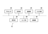
- FIG. 2A is a diagram showing an example of the configuration of the head mounted display (HMD) 12 according to the present embodiment.
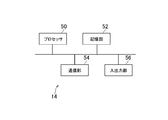
- FIG. 2B is a diagram showing an example of the configuration of the entertainment device 14 according to the present embodiment.
- HMD head mounted display
- an entertainment system 10 includes an HMD 12, an entertainment device 14, a relay device 16, a display 18, a camera microphone unit 20, and a controller 22.
- the HMD 12 includes, for example, as shown in FIG. 2A, a processor 30, a storage unit 32, a communication unit 34, an input / output unit 36, a display unit 38, a sensor unit 40, and a swing unit 42.
- the processor 30 is a program control device such as a microprocessor that operates according to a program installed in the HMD 12, for example.
- the storage unit 32 is, for example, a storage element such as a ROM or RAM.
- the storage unit 32 stores a program executed by the processor 30 and the like.
- the communication unit 34 is a communication interface such as a wireless LAN module.
- the input / output unit 36 is an input / output port such as an HDMI (registered trademark) (High-Definition Multimedia Interface) port or a USB port.
- HDMI registered trademark
- High-Definition Multimedia Interface High-Definition Multimedia Interface
- the display unit 38 is, for example, a display such as a liquid crystal display or an organic EL display, and displays an image generated by the entertainment device 14. As shown in FIG. 1, when the user wears the HMD 12, the display unit 38 is placed in front of the user's eyes.
- the display unit 38 may receive, for example, a video signal output by the entertainment apparatus 14 and relayed by the relay apparatus 16, and output the video represented by the video signal.
- the display unit 38 according to this embodiment can display a three-dimensional image by displaying an image for the left eye and an image for the right eye, for example.
- the display unit 38 may not be able to display a three-dimensional image but only a two-dimensional image.
- the sensor unit 40 is, for example, a sensor such as an acceleration sensor or a motion sensor.
- the sensor unit 40 may output measurement results such as the posture, rotation amount, and movement amount of the HMD 12 to the processor 30 at a predetermined sampling rate.
- the oscillating unit 42 is a device that oscillates according to an input signal, for example.
- the swinging part 42 is provided on the front surface of the housing 44 of the HMD 12.
- the swing unit 42 may be, for example, a vibrator such as a vibration motor.
- the oscillating portion 42 is an eccentric motor, the weight included in the oscillating portion 42 rotates as an axis substantially in the front-rear direction according to an input signal, so that the oscillating portion 42 vibrates. You can
- one swinging part 42 is provided in the center of the front surface of the housing 44 of the HMD 12.
- the swing unit 42 can swing the head of the user wearing the HMD 12.
- the HMD 12 may be provided with a plurality of swinging parts 42. Further, in this case, the plurality of swing portions 42 may be provided symmetrically.
- the entertainment device 14 is a computer such as a game console, a DVD player, a Blu-ray (registered trademark) player, or the like.
- the entertainment apparatus 14 according to the present embodiment generates video and audio, for example, by executing a game program stored in or recorded on an optical disk, reproduction of content, and the like. Then, the entertainment apparatus 14 according to the present embodiment outputs a video signal representing a generated video and an audio signal representing a generated sound to the display 18 via the relay device 16.
- the entertainment device 14 includes a processor 50, a storage unit 52, a communication unit 54, and an input / output unit 56, as shown in FIG. 2B, for example.
- the processor 50 is, for example, a program control device such as a CPU that operates according to a program installed in the entertainment apparatus 14.
- the processor 50 according to the present embodiment also includes a GPU (Graphics Processing Unit) that draws an image in the frame buffer based on graphics commands and data supplied from the CPU.
- GPU Graphics Processing Unit
- the storage unit 52 is, for example, a storage element such as a ROM or RAM or a hard disk drive.
- the storage unit 52 stores a program executed by the processor 50 and the like. Further, in the storage unit 52 according to the present embodiment, an area of the frame buffer in which an image is drawn by the GPU is secured.
- the communication unit 54 is, for example, a communication interface such as a wireless LAN module.
- the input / output unit 56 is an input / output port such as an HDMI (registered trademark) (High-Definition Multimedia Interface) port and a USB port.
- HDMI registered trademark
- USB Universal Serial Bus
- the relay device 16 is a computer including, for example, a control unit such as a control circuit, an image processing circuit, a voice processing circuit, a storage unit such as a memory, and the like.
- the relay device 16 relays the video signal and the audio signal output from the entertainment device 14 and outputs them to the HMD 12 and the display 18.
- the display 18 is, for example, a liquid crystal display or the like, and displays an image represented by a video signal output from the entertainment device 14.
- the camera microphone unit 20 includes, for example, a camera 20a that outputs a captured image of a subject to the entertainment device 14 and a microphone that acquires ambient audio, converts the audio into audio data, and outputs the audio data to the entertainment device 14. 20b is included.
- the camera 20a according to this embodiment is a stereo camera.
- the HMD 12 and the relay device 16 are capable of wirelessly transmitting and receiving data, for example.
- the HMD 12 and the relay device 16 may be connected via a cable such as an HDMI cable or a USB cable.
- the entertainment device 14 and the relay device 16 are connected via, for example, an HDMI cable or a USB cable.
- the relay device 16 and the display 18 are connected via, for example, an HDMI cable or the like.
- the entertainment device 14 and the camera microphone unit 20 are connected via, for example, an AUX cable.
- the controller 22 according to the present embodiment is an operation input device for performing an operation input to the entertainment device 14.
- the user can perform various operation inputs by using the controller 22 by pressing direction keys or buttons provided on the controller 22 or tilting the operation stick.
- the controller 22 outputs the input data associated with the operation input to the entertainment device 14.
- the controller 22 according to the present embodiment has a USB port.
- the controller 22 can output the input data to the entertainment device 14 in a wired manner by connecting to the entertainment device 14 with a USB cable.
- the controller 22 according to the present embodiment includes a wireless communication module and the like, and is also capable of wirelessly outputting input data to the entertainment device 14.
- the entertainment device 14 executes a first-person viewpoint game program. Then, for example, a moving image representing a state in which the shooting direction 64 is viewed from the virtual camera 62 arranged in the virtual space 60 shown in FIG. 3 is generated.
- a frame image representing a state in which the shooting direction 64 is viewed from the position of the virtual camera 62 in the frame is generated.
- the virtual space 60 shown in FIG. 3 is a virtual three-dimensional space. The position of the virtual camera 62 and the shooting direction 64 change according to the playing situation of the game such as an operation of the controller 22 by the player or an event occurring in the game.
- the content displayed on the display unit 38 of the HMD 12 changes according to the position of the virtual camera 62 and the change of the shooting direction 64.
- the processing according to the play status of the game including the update of the position of the virtual camera 62 and the shooting direction 64, the generation of the frame image, and the display of the frame image may be executed at the above-described predetermined frame rate.
- the acceleration motion refers to, for example, circular motion, uniform acceleration motion, variable acceleration motion, or the like.
- the motion indicated by the acceleration motion may or may not include angular acceleration motion such as equiangular acceleration motion and variable angular acceleration motion.
- angular acceleration motion such as equiangular acceleration motion and variable angular acceleration motion.
- a first-person viewpoint game when the first-person viewpoint character jumps or dashes, it is determined that the virtual camera 62 is accelerating.
- whether or not the virtual camera 62 is accelerating may be determined based on the position of the virtual camera 62 and the shooting direction 64 in the latest predetermined number of frames.
- the swing of the swing unit 42 (for example, whether to swing the swing unit 42) is controlled according to the result of the determination.
- the oscillating portion 42 is a vibration motor, even if the vibration motor is controlled to vibrate such that the frequency band is 10 to 20 Hertz and the acceleration value (G value) is 0.05 to 0.5 G. Good.
- the swing unit 42 is swung according to whether or not the moving image displayed on the display unit 38 represents the situation in which the virtual camera 62 is accelerating. Whether or not is controlled.
- the motion sickness of a user wearing the HMD 12 is the motion of the viewpoint in the situation where a moving image showing the appearance from the viewpoint is displayed on the display unit 38 arranged in front of the user. It is considered that the difference from the user's experience is caused.
- the position of the viewpoint corresponds to the position of the virtual camera 62.
- the direction of the viewpoint corresponds to the shooting direction 64. That is, it is considered that the VR sickness in the above example is caused by the difference between the movement of the virtual camera 62 and the user's sensation. In particular, the sensation of the head where sensory organs are concentrated seems to have a great influence on VR sickness.
- the swing of the swing unit 42 is controlled according to the viewpoint acceleration state in the moving image displayed on the display unit 38. For example, as described above, whether or not the rocking unit 42 is rocked depending on whether or not the moving image displayed on the display unit 38 represents a situation in which the viewpoint is accelerating. Is controlled. In this way, according to the present embodiment, VR motion sickness can be further reduced by linking the displayed moving image with the swing of the head.
- the present invention not only the scene in which the moving image of the virtual space 60 photographed by the virtual camera 62 is displayed on the display unit 38, but the moving image of the real space photographed by the real camera is displayed on the display unit 38.
- the same can be applied to the scene.
- whether or not the rocking portion 42 is rocked may be controlled depending on whether or not the actual camera represents a situation in which the camera is accelerating.
- the present invention can be similarly applied to a general moving image representing a state from a viewpoint, such as a moving image of movie content, which is not a moving image captured by the real camera or the virtual camera 62.
- the swinging part 42 according to the present embodiment is provided on the front surface of the housing 44 of the HMD 12. Therefore, the swinging part 42 can be easily attached to the HMD 12.
- the swinging part 42 need not be provided on the front surface of the housing 44 of the HMD 12 as long as the head of the user wearing the HMD 12 can be swung.
- the swing unit 42 may be provided on the inner surface of the housing 44. Further, the swinging part 42 does not need to be provided on the HMD 12.
- FIG. 4 is a diagram schematically showing an example of the data structure of the swing control moving image data 66 according to the present embodiment.
- the swing control moving image data 66 shown in FIG. 4 may be generated.
- the swing control moving image data 66 includes, for example, moving image data 68 and swing control data 70.
- the moving image data 68 is, for example, data indicating a moving image that is displayed on the display unit 38 by being reproduced and that represents the appearance from the viewpoint.
- the moving image data 68 indicating the moving image may be generated. Good.
- the swing control data 70 is, for example, data that can specify the acceleration state of the viewpoint in the moving image indicated by the moving image data 68.
- the rocking control data 70 may be, for example, data that can specify a frame image in which the viewpoint is accelerating in the moving image represented by the moving image data 68.
- the moving image data 68 includes a plurality of frame images generated at a predetermined frame rate.
- the rocking control data 70 includes a plurality of frame rocking control data associated with each frame image.
- the frame rocking control data is set to 1 if the associated frame image represents a situation in which the viewpoint is accelerating, and is set to 0 if it does not represent a situation in which the viewpoint is accelerating. It may be a flag.
- the frame rocking control data associated with the frame image showing the situation in which the viewpoint is accelerating, that is, the frame rocking control data having a value of 1 is schematically painted in black. Is expressed in.
- the data format of the rocking control data 70 is not limited to the above.
- the swing control data 70 may be data indicating a frame number of a frame image in which a situation in which the viewpoint is accelerating is displayed.
- the swing control data 70 may be set, for example, according to an operation performed by an operator while watching the moving image represented by the moving image data 68. For example, for a frame image that the operator has determined that the viewpoint is accelerating, the operator may perform an operation of setting 1 as the value of the frame rocking control data associated with the frame image. Then, 1 may be set as the value of the frame swing control data in accordance with the operation.
- each frame image is a frame image showing a situation in which the viewpoint is accelerating.
- Good For example, whether or not the frame image shows a situation in which the viewpoint is accelerating may be determined based on a predetermined number of continuous frame images up to the frame image. Then, the swing control data 70 may be generated based on the specific result.
- the swing control data 70 may be generated based on the result of the above-described determination of whether or not the virtual camera 62 is accelerating based on the movement of the virtual camera 62.
- 1 may be set as the value of the frame swing control data associated with the frame image displayed at the timing when the swing unit 42 is controlled to swing.
- the swing based on the swing control data 70 included in the swing control moving image data 66 Dynamic control may be performed. For example, based on the rocking control data 70, it may be determined whether or not the frame image showing the situation in which the viewpoint is accelerating is displayed on the display unit 38. Then, when it is determined that the frame image showing that the viewpoint is accelerating is displayed, the swing unit 42 may be controlled to swing. For example, when the value of the frame swing control data associated with the frame image displayed on the display unit 38 is 1, the swing unit 42 may swing.
- the acceleration value or the angular acceleration value of the viewpoint may be determined. Then, swing control may be performed according to the acceleration value or the angular acceleration value.
- the oscillating unit 42 may be controlled so that the oscillating unit 42 oscillates more as the acceleration value or the angular acceleration value increases.
- the oscillating unit 42 sets a predetermined value regardless of the acceleration value or the angular acceleration value of the viewpoint. It may be controlled to swing in magnitude.
- the swing control moving image data 66 is generated in real time during the game play, and the swing control moving image data 66 is transmitted to another entertainment system 10 connected via a network. The transmission may be performed. Then, in the entertainment system 10 that has received the swing control moving image data 66, the moving image represented by the moving image data 68 included in the swing control moving image data 66 may be displayed. Further, in the entertainment system 10 that has received the swing control moving image data 66, the swing that is linked to the displayed moving image based on the swing control data 70 included in the swing control moving image data 66 as described above. The swing control of the portion 42 may be performed.
- FIG. 5 is a functional block diagram showing an example of functions implemented in the entertainment apparatus 14 according to the present embodiment.
- the entertainment device 14 according to the present embodiment does not need to have all the functions shown in FIG. 5, and may have functions other than those shown in FIG.
- the entertainment apparatus 14 functionally has, for example, a program execution unit 80, a moving image data generation unit 82, a determination unit 84, a swing control data generation unit 86, a swing.
- a control moving image data generation unit 88, a swing control moving image data storage unit 90, a swing control moving image data acquisition unit 92, a display control unit 94, and a swing control unit 96 are included.
- the program execution unit 80, the moving image data generation unit 82, the determination unit 84, the swing control data generation unit 86, and the swing control moving image data generation unit 88 are implemented mainly by the processor 50.
- the swing control moving image data storage unit 90 is implemented mainly by the storage unit 52.
- the swing control moving image data acquisition unit 92 is implemented mainly by the processor 30 or the communication unit 54.
- the display control unit 94 and the swing control unit 96 are mainly mounted on the processor 50 and the input / output unit 56.
- the above functions are implemented by executing a program, which is installed in the entertainment device 14 which is a computer, including instructions corresponding to the above functions, in the processor 50.
- the program is supplied to the entertainment apparatus 14 via a computer-readable information storage medium such as an optical disc, a magnetic disc, a magnetic tape, a magneto-optical disc, a flash memory, or the like, or via the Internet or the like.
- the program execution unit 80 executes a program such as a game program, for example.
- the moving image data generation unit 82 generates moving image data 68 indicating a moving image according to the execution result of the program by the program execution unit 80, such as a moving image according to the playing status of the game.
- the moving image data generation unit 82 may generate a moving image showing how the virtual space 60 is viewed from the virtual camera 62 arranged in the virtual space 60.
- the determination unit 84 determines, for example, the acceleration state of the viewpoint in the frame image displayed on the display unit 38.
- the determination unit 84 may determine whether or not the frame image showing the situation in which the viewpoint is accelerating is displayed on the display unit 38.
- the determination unit 84 may determine whether or not the virtual camera 62 is accelerating in the virtual space 60, for example.
- the motion indicated by the acceleration motion may or may not include the angular acceleration motion.
- the swing control data generation unit 86 generates the swing control data 70 described above, for example.
- the swing control data generation unit 86 controls swing based on the result of the determination by the determination unit 84 whether the virtual camera 62 arranged in the virtual space 60 is accelerating in the virtual space 60.
- the data 70 may be generated.
- the rocking control data generation unit 86 may generate the rocking control data 70 based on the moving image data 68 showing the moving image showing the appearance from the viewpoint.
- the swing control data generation unit 86 may generate the swing control data 70 based on the moving image data 68 generated by the moving image data generation unit 82.
- the swing control moving image data generation unit 88 generates, for example, the swing control moving image data 66 described above.
- the swing control moving image data generation unit 88 includes, for example, the moving image data 68 generated by the moving image data generation unit 82 and the swing control data 70 generated by the swing control data generation unit 86.
- the motion control moving image data 66 may be generated.
- the moving image data 68 is data indicating a moving image showing a state where the virtual space 62 is viewed from the virtual camera 62
- the swing control data 70 is such that the virtual camera 62 performs an acceleration motion in the virtual space 60.
- the data may be data according to the result of the determination as to whether or not it is.
- the moving image data 68 included in the swing control moving image data 66 does not have to be the moving image data 68 indicating the moving image according to the execution result of the program by the program executing unit 80.
- the moving image data 68 included in the swing control moving image data 66 may be, for example, the moving image data 68 indicating a moving image in a real space captured by a real camera, as described above. Further, the moving image data 68 does not have to indicate a moving image according to the playing situation of the game, and may be a moving image of a content such as a movie, for example. Further, the moving image indicated by the moving image data 68 does not need to be a moving image captured by the real camera or the virtual camera 62.
- the swing control moving image data storage unit 90 stores, for example, the swing control moving image data 66 described above in the present embodiment.
- the swing control moving image data storage unit 90 may store the swing control moving image data 66 generated by the swing control moving image data generation unit 88.
- the swing control moving image data 66 may be purchaseable by the user. Then, the swing control moving image data 66 purchased by the user may be stored in the swing control moving image data storage unit 90.
- the rocking control moving image data acquisition unit 92 acquires the rocking control moving image data 66, for example.
- the swing control moving image data acquisition unit 92 may obtain the swing control moving image data 66 stored in the swing control moving image data storage unit 90. Further, the swing control moving image data acquisition unit 92 may receive the swing control moving image data 66 transmitted from another entertainment system 10.
- the display control unit 94 causes the display unit 38 to display, for example, a moving image representing a state viewed from the viewpoint.
- the display control unit 94 may transmit the moving image to the HMD 12 via the relay device 16. Then, the HMD 12 may display the received moving image on the display unit 38.
- the display control unit 94 may also cause the display unit 38 to display a moving image showing a state in which the virtual space 60 is viewed from the virtual camera 62 arranged in the virtual space 60. Further, the display control unit 94 may cause the display unit 38 to display a moving image showing a state of viewing the real space from a real camera arranged in the real space.
- the display control unit 94 may also cause the display unit 38 to display a moving image indicated by the moving image data 68 included in the swing control moving image data 66 acquired by the swing control moving image data acquisition unit 92.
- the swing control unit 96 controls the swing of the swing unit 42 according to, for example, the acceleration state of the viewpoint in the moving image displayed on the display unit 38.
- the swing control unit 96 determines whether the moving image displayed on the display unit 38 and representing the appearance from the viewpoint represents a situation in which the viewpoint is accelerating. You may control whether 42 is rocked.
- the swing control unit 96 may transmit a control signal for controlling the swing unit 42 to the HMD 12 via the relay device 16. Then, the HMD 12 may perform swing control of the swing unit 42 based on the received control signal.
- the swing control unit 96 may control whether to swing the swing unit 42 according to the result of the determination made by the determination unit 84.
- the determination unit 84 based on the rocking control data 70 included in the rocking control moving image data 66 acquired by the rocking control moving image data acquisition unit 92, a frame image showing a situation in which the viewpoint is accelerating. It may be determined whether or not is displayed on the display unit 38. For example, when the value of the frame rocking control data associated with the displayed frame image is 1, it is determined that the frame image showing the situation where the viewpoint is accelerating is displayed on the display unit 38. May be. Then, the swing control unit 96 may control whether to swing the swing unit 42 according to the result of the determination made by the determination unit 84.
- the processing example illustrated in FIG. 6 is an example of the flow of the swing control processing of the swing unit 42 based on the movement of the virtual camera 62.
- the empty rocking control moving image data storage unit 90 stores the empty rocking control moving image data 66 generated in advance by the rocking control moving image data generation unit 88.
- processing shown in S101 to S107 shown in FIG. 6 is repeatedly executed at a predetermined frame rate.
- the program execution unit 80 changes the position of the virtual camera 62 and the shooting direction 64 based on the game play status including an operation signal received from the controller 22 and an event that occurred in the game (S101).
- the moving image data generation unit 82 generates a frame image showing how the virtual camera 62 looks at the shooting direction 64 (S102).
- the determination unit 84 determines whether or not the virtual camera 62 is accelerating (S103).
- the display control unit 94 executes the display control for displaying the frame image generated in the process of S102 on the display unit 38 of the HMD 12, and the swing control unit 96 swings the swing unit 42.
- the rocking control is performed (S104). In this case, the swing part 42 swings.
- the display control unit 94 executes display control for displaying the frame image generated in the process of S102 on the display unit 38 of the HMD 12 (S105).
- the swing part 42 does not swing.
- the swing control section 96 may perform swing control that does not swing the swing section 42.
- the swing control data generation unit 86 When the processing shown in S104 or S105 ends, the swing control data generation unit 86 generates frame swing control data in this loop according to the determination result in the processing shown in S103 (S106).
- frame swing control data having a value of 1 is generated.
- frame swing control data having a value of 0 is generated.
- the swing control moving image data generation unit 88 updates the swing control moving image data 66 stored in the swing control moving image data storage unit 90 (S107).
- the frame image generated by the process shown in S102 is added to the moving image data 68 included in the swing control moving image data 66.
- the frame rocking control data in the present loop generated by the processing shown in S106 is added to the rocking control data 70 included in the rocking control moving image data 66 in a state associated with the frame image. It Then, the process returns to S101.
- FIG. 7 The processing example shown in FIG. 7 is performed by the swing unit when the moving image represented by the moving image data 68 included in the swing control moving image data 66 acquired by the swing control moving image data acquisition unit 92 is reproduced. It is an example of the flow of the swing control process of 42.
- the display control unit 94 identifies the frame image in this loop, which is shown in the moving image data 68 included in the swing control moving image data 66 (S201).
- the determination unit 84 represents the situation in which the frame image specified by the processing shown in S201 based on the swing control data 70 included in the swing control moving image data 66 is accelerating the viewpoint. It is determined whether or not (S202).
- S202 the frame image identified by the process of S201
- the frame image identified by the process of S201 has its viewpoint accelerated. It is determined that it represents the situation in which there is.
- the frame image identified by the process of S201 shows a situation in which the viewpoint is accelerating. It is determined that it does not represent.
- the frame image identified by the process shown in S201 is determined to represent a situation in which the viewpoint is accelerating (S202: Y).
- the display control unit 94 executes the display control for displaying the frame image specified in the process of S201 on the display unit 38 of the HMD 12, and the swing control unit 96 swings the swing unit 42.
- the rocking control is performed (S203). In this case, the swing part 42 swings.
- the display control unit 94 executes the display control for displaying the frame image generated in the process shown in S102 on the display unit 38 of the HMD 12 (S204).
- the swing part 42 does not swing.
- the swing control section 96 may perform swing control that does not swing the swing section 42.
- the swing control unit 96 determines the result of the determination by the determination unit 84 and the distance d between the virtual object 100 and the virtual camera 62 arranged in the virtual space 60 shown in FIG. Based on this, the swing of the swing unit 42 may be controlled. For example, the swing control unit 96 swings the swing unit 42 based on the result of the determination by the determination unit 84 and the distance d between the virtual object 100 arranged in the virtual space 60 and the virtual camera 62. You may control whether to move.
- the swing control unit 96 determines, based on the result of the determination made by the determination unit 84, and the distance d between the virtual object 100 and the virtual camera 62 arranged within the angle of view (shooting range) of the virtual camera 62.
- the swing of the swing unit 42 may be controlled.
- the swing control unit 96 may specify the distance d between the position P1 of the viewpoint of the virtual camera 62 and the position P2 of the point on the surface of the virtual object 100 that is closest to the position P1 of the viewpoint. ..
- the swing control unit 96 may also specify the distance d between the virtual camera 62 and the virtual object closest to the virtual camera 62 specified from the plurality of virtual objects.
- the swing control unit 96 may identify the virtual object closest to the virtual camera 62 from these virtual objects. Then, the swing control unit 96 may specify the distance d between the specified virtual object and the virtual camera 62.
- the swing control unit 96 causes the swing unit 96 to swing. Swing control for swinging 42 may be executed.
- the swing control unit 96 may control the swing amount of the swing unit 42 based on the distance d between the virtual object 100 arranged in the virtual space 60 and the virtual camera 62. For example, the swing control unit 96 may determine the swing amount of the swing unit 42 based on the distance d. Then, the swing control unit 96 may control the swing unit 42 to swing by the determined swing amount. Here, for example, a larger swing amount may be determined as the distance d is shorter. In this case, the swinging part 42 is controlled so that the swinging part 42 swings more as the distance d becomes shorter.
- the swing control unit 96 may specify an object shown in the moving image represented by the moving image data 68 by using an image analysis technique. Then, the swing control unit 96 may specify the amount of movement of the specified object within the frame image per unit time. In this case, even if the display unit 38 is capable of displaying a three-dimensional image, the swing control unit 96 may replace the three-dimensional image with the two-dimensional image and specify the amount of movement of the object. That is, when specifying the amount of movement of the object, the movement of the object in the depth direction need not be considered.
- the swing control unit 96 may control the swing of the swing unit 42 based on the specified movement amount.
- the swing control unit 96 may control whether to swing the swing unit 42 based on the specified amount of movement, for example.
- the rocking control unit 96 may perform rocking control for rocking the rocking unit 42, for example, when the specified movement amount is larger than a predetermined movement amount.
- the swing control unit 96 may control the swing amount of the swing unit 42 based on the specified movement amount. For example, the swinging unit 42 may be controlled so that the swinging unit 42 swings more as the specified movement amount increases.
- the distance between the position of the center of the object appearing in the frame image of a frame and the position of the center of the object appearing in the frame image of the frame immediately preceding the frame may be specified. Then, the swing of the swing unit 42 may be controlled based on the specified distance. For example, when the specified distance is larger than the predetermined distance, the rocking control unit 96 may execute rocking control for rocking the rocking unit 42. Further, the swinging unit 42 may be controlled so that the swinging unit 42 swings more as the specified distance increases.
- the object having the largest movement amount per unit time within the frame image may be specified. Then, the swing of the swing unit 42 may be controlled based on the amount of movement of the identified object per unit time.
- the swing control unit 96 may specify the difference between the pixel value of the pixel included in the frame image of the frame and the pixel value of the pixel corresponding to the pixel included in the frame image of the immediately previous frame. Good. Then, the swing controller 96 may control the swing of the swing unit 42 based on the sum of the pixel value differences specified for all the pixels. For example, when the specified total is larger than the predetermined value, the rocking control unit 96 may execute rocking control to rock the rocking unit 42. Further, the swinging unit 42 may be controlled such that the swinging unit 42 swings more as the specified total increases.
- FIG. 9 is another example of the swing control processing flow of the swing unit 42 based on the movement of the virtual camera 62 as shown in FIG.
- the empty rocking control moving image data storage unit 90 stores the empty rocking control moving image data 66 generated in advance by the rocking control moving image data generation unit 88.
- processing shown in S301 to S308 shown in FIG. 9 is repeatedly executed at a predetermined frame rate.
- the swing control unit 96 specifies the distance d between the virtual camera 62 and the virtual object 100 as described above, and determines whether or not the distance d is shorter than the predetermined distance d1. (S304).
- the display control unit 94 executes the display control for displaying the frame image generated by the process shown in S302 on the display unit 38 of the HMD 12, and the swing control unit 96. Performs rocking control for rocking the rocking portion 42 (S305). In this case, the swing part 42 swings.
- the display control unit 94 executes display control for displaying the frame image generated by the process shown in S302 on the display unit 38 of the HMD 12 (S306).
- the swing part 42 does not swing.
- the swing control section 96 may perform swing control that does not swing the swing section 42.
- the swing control data generation unit 86 When the process of S305 or S306 is completed, the swing control data generation unit 86 generates frame swing control data in this loop according to the determination result in the processes of S303 and S304 (S307).
- frame swing control data having a value of 1 is generated.
- frame swing control data having a value of 0 is generated.
- the swing control moving image data generation unit 88 updates the swing control moving image data 66 stored in the swing control moving image data storage unit 90 (S308).
- the frame image generated in the process of S302 is added to the moving image data 68 included in the swing control moving image data 66.
- the frame rocking control data in the present loop generated in the processing shown in S307 is added to the rocking control data 70 included in the rocking control moving image data 66 in a state of being associated with the frame image. It Then, the process returns to S301.
- FIG. 10 is performed when the moving image represented by the moving image data 68 included in the swing control moving image data 66 generated by the processing shown in S301 to S308 shown in FIG. 9 is reproduced.
- 7 is an example of the flow of swing control processing of the moving unit 42.
- processing shown in S401 to S404 shown in FIG. 10 is repeatedly executed at a predetermined frame rate.
- the display control unit 94 identifies the frame image in this loop, which is shown in the moving image data 68 included in the swing control moving image data 66 (S401).
- the determination unit 84 confirms whether or not the value of the frame rocking control data associated with the frame image identified by the process shown in S401 is 1 (S402).
- the display control unit 94 executes the display control to display the frame image specified in the process of S201 on the display unit 38 of the HMD 12, and the swing control unit 96 swings the swing unit 42.
- the rocking control is performed (S403). In this case, the swing part 42 swings.
- the display control unit 94 executes display control for displaying the frame image generated in the process of S102 on the display unit 38 of the HMD 12 (S404).
- the swing part 42 does not swing.
- the swing control section 96 may perform swing control that does not swing the swing section 42.
- the frame rocking control data described above may be data indicating a rocking amount.
- the swing control data generation unit 86 may generate frame swing control data indicating the swing amount.
- the swing control data generation unit 86 may generate frame swing control data having a value of 0.
- the swing control unit 96 may perform swing control in which the swing unit 42 is swung so as to swing by the swing amount indicated by the frame swing control data.
- the present invention is not limited to the above embodiment.
- the division of roles of the HMD 12, the entertainment device 14, and the relay device 16 is not limited to the above.
- some or all of the functions shown in FIG. 5 may be implemented by the HMD 12.
- the rocking control unit 96 may switch the rocking control of the rocking unit 42 between on and off by a user's operation or the like.
Landscapes
- Engineering & Computer Science (AREA)
- Theoretical Computer Science (AREA)
- Multimedia (AREA)
- Physics & Mathematics (AREA)
- General Engineering & Computer Science (AREA)
- General Physics & Mathematics (AREA)
- Human Computer Interaction (AREA)
- Computer Hardware Design (AREA)
- Signal Processing (AREA)
- Computer Vision & Pattern Recognition (AREA)
- Optics & Photonics (AREA)
- Processing Or Creating Images (AREA)
- User Interface Of Digital Computer (AREA)
Priority Applications (6)
| Application Number | Priority Date | Filing Date | Title |
|---|---|---|---|
| CN201980069436.7A CN112913225B (zh) | 2018-11-01 | 2019-10-16 | Vr晕动病减轻系统,头戴式显示器,vr晕动病减轻方法 |
| CN202411528993.XA CN119544947A (zh) | 2018-11-01 | 2019-10-16 | Vr晕动病减轻系统、头戴式显示器、vr晕动病减轻方法 |
| US17/287,004 US11687159B2 (en) | 2018-11-01 | 2019-10-16 | VR sickness reduction system, head-mounted display, VR sickness reduction method, and program |
| EP19879075.0A EP3876524A4 (en) | 2018-11-01 | 2019-10-16 | VR TRAVEL SICKNESS REDUCTION SYSTEM, HEADSET, VR TRAVEL SICKNESS REDUCTION METHOD, AND PROGRAM |
| JP2020553765A JP7382954B2 (ja) | 2018-11-01 | 2019-10-16 | Vr酔い低減システム、ヘッドマウントディスプレイ、vr酔い低減方法及びプログラム |
| US18/316,709 US20230280834A1 (en) | 2018-11-01 | 2023-05-12 | Vr sickness reduction system, head-mounted display, vr sickness reduction method, and program |
Applications Claiming Priority (2)
| Application Number | Priority Date | Filing Date | Title |
|---|---|---|---|
| JP2018-206572 | 2018-11-01 | ||
| JP2018206572 | 2018-11-01 |
Related Child Applications (2)
| Application Number | Title | Priority Date | Filing Date |
|---|---|---|---|
| US17/287,004 A-371-Of-International US11687159B2 (en) | 2018-11-01 | 2019-10-16 | VR sickness reduction system, head-mounted display, VR sickness reduction method, and program |
| US18/316,709 Continuation US20230280834A1 (en) | 2018-11-01 | 2023-05-12 | Vr sickness reduction system, head-mounted display, vr sickness reduction method, and program |
Publications (1)
| Publication Number | Publication Date |
|---|---|
| WO2020090477A1 true WO2020090477A1 (ja) | 2020-05-07 |
Family
ID=70464060
Family Applications (1)
| Application Number | Title | Priority Date | Filing Date |
|---|---|---|---|
| PCT/JP2019/040723 Ceased WO2020090477A1 (ja) | 2018-11-01 | 2019-10-16 | Vr酔い低減システム、ヘッドマウントディスプレイ、vr酔い低減方法及びプログラム |
Country Status (5)
| Country | Link |
|---|---|
| US (2) | US11687159B2 (https=) |
| EP (1) | EP3876524A4 (https=) |
| JP (1) | JP7382954B2 (https=) |
| CN (2) | CN112913225B (https=) |
| WO (1) | WO2020090477A1 (https=) |
Cited By (5)
| Publication number | Priority date | Publication date | Assignee | Title |
|---|---|---|---|---|
| US11284205B2 (en) | 2016-11-14 | 2022-03-22 | Otolith Sound Inc. | Systems, devices, and methods for treating vestibular conditions |
| WO2023079748A1 (ja) | 2021-11-08 | 2023-05-11 | 株式会社ソニー・インタラクティブエンタテインメント | ヘッドマウントディスプレイ |
| WO2023171422A1 (ja) * | 2022-03-10 | 2023-09-14 | 株式会社ソニー・インタラクティブエンタテインメント | 表示制御システム、表示制御方法、プログラム |
| US12053426B2 (en) | 2014-09-29 | 2024-08-06 | Otolith Sound Inc. | Device for mitigating motion sickness and other responses to inconsistent sensory information |
| US12422928B2 (en) | 2021-07-12 | 2025-09-23 | Sony Group Corporation | Information processing apparatus, information processing method, and program |
Families Citing this family (2)
| Publication number | Priority date | Publication date | Assignee | Title |
|---|---|---|---|---|
| JP2021124529A (ja) * | 2020-01-31 | 2021-08-30 | キヤノン株式会社 | 画像処理装置、画像処理システム、画像処理方法、及びプログラム |
| TWI815353B (zh) * | 2022-03-16 | 2023-09-11 | 國立清華大學 | 用於減緩動暈症的頭戴式裝置 |
Citations (2)
| Publication number | Priority date | Publication date | Assignee | Title |
|---|---|---|---|---|
| US20150325027A1 (en) | 2014-05-09 | 2015-11-12 | Dreamworks Animation Llc | Method and system for reducing motion sickness in virtual reality ride systems |
| JP2017182130A (ja) * | 2016-03-28 | 2017-10-05 | ソニー株式会社 | 情報処理装置、情報処理方法、及びプログラム |
Family Cites Families (18)
| Publication number | Priority date | Publication date | Assignee | Title |
|---|---|---|---|---|
| JP2000339490A (ja) * | 1999-05-28 | 2000-12-08 | Mitsubishi Electric Corp | Vr酔い低減方法 |
| US8619080B2 (en) * | 2008-09-08 | 2013-12-31 | Disney Enterprises, Inc. | Physically present game camera |
| AU2009291915B2 (en) * | 2008-09-09 | 2015-03-12 | New York University | Method and devices to increase craniofacial bone density |
| US8553783B2 (en) * | 2008-12-29 | 2013-10-08 | Stmicroelectronics Asia Pacific Pte Ltd. | Apparatus and method of motion detection for temporal mosquito noise reduction in video sequences |
| US9094749B2 (en) * | 2012-07-25 | 2015-07-28 | Nokia Technologies Oy | Head-mounted sound capture device |
| WO2014100484A1 (en) * | 2012-12-19 | 2014-06-26 | HeadsUp Technologies, Inc. | Methods and systems for managing motion sickness |
| US9549870B2 (en) * | 2013-05-27 | 2017-01-24 | Iman Shafieloo | Smart joint care |
| KR101507242B1 (ko) * | 2013-10-21 | 2015-03-31 | 포항공과대학교 산학협력단 | 영상 분석을 통하여 모션 햅틱 효과를 제공하는 장치 및 방법 |
| US9999835B2 (en) | 2015-02-05 | 2018-06-19 | Sony Interactive Entertainment Inc. | Motion sickness monitoring and application of supplemental sound to counteract sickness |
| US10162412B2 (en) * | 2015-03-27 | 2018-12-25 | Seiko Epson Corporation | Display, control method of display, and program |
| JP6707823B2 (ja) | 2015-09-03 | 2020-06-10 | セイコーエプソン株式会社 | 表示装置、表示装置の制御方法、及び、プログラム |
| US10594936B2 (en) * | 2015-09-25 | 2020-03-17 | Sony Interactive Entertainment Inc. | Head mounted display having a plurality of display modes |
| JP6448527B2 (ja) * | 2015-12-10 | 2019-01-09 | キヤノン株式会社 | 周波数制御装置、モータ駆動装置および光学機器 |
| JP6689694B2 (ja) * | 2016-07-13 | 2020-04-28 | 株式会社バンダイナムコエンターテインメント | シミュレーションシステム及びプログラム |
| KR20180042971A (ko) * | 2016-10-19 | 2018-04-27 | 현대자동차주식회사 | 차량 및 차량의 제어방법 |
| JP2018082363A (ja) * | 2016-11-18 | 2018-05-24 | セイコーエプソン株式会社 | 頭部装着型表示装置およびその制御方法、並びにコンピュータープログラム |
| JP6246310B1 (ja) * | 2016-12-22 | 2017-12-13 | 株式会社コロプラ | 仮想空間を提供するための方法、プログラム、および、装置 |
| CN107621883B (zh) * | 2017-10-18 | 2020-05-08 | 炫彩互动网络科技有限公司 | 一种基于手机终端的虚拟现实系统及人机交互方法 |
-
2019
- 2019-10-16 WO PCT/JP2019/040723 patent/WO2020090477A1/ja not_active Ceased
- 2019-10-16 EP EP19879075.0A patent/EP3876524A4/en active Pending
- 2019-10-16 US US17/287,004 patent/US11687159B2/en active Active
- 2019-10-16 CN CN201980069436.7A patent/CN112913225B/zh active Active
- 2019-10-16 JP JP2020553765A patent/JP7382954B2/ja active Active
- 2019-10-16 CN CN202411528993.XA patent/CN119544947A/zh active Pending
-
2023
- 2023-05-12 US US18/316,709 patent/US20230280834A1/en active Pending
Patent Citations (2)
| Publication number | Priority date | Publication date | Assignee | Title |
|---|---|---|---|---|
| US20150325027A1 (en) | 2014-05-09 | 2015-11-12 | Dreamworks Animation Llc | Method and system for reducing motion sickness in virtual reality ride systems |
| JP2017182130A (ja) * | 2016-03-28 | 2017-10-05 | ソニー株式会社 | 情報処理装置、情報処理方法、及びプログラム |
Cited By (10)
| Publication number | Priority date | Publication date | Assignee | Title |
|---|---|---|---|---|
| US12053426B2 (en) | 2014-09-29 | 2024-08-06 | Otolith Sound Inc. | Device for mitigating motion sickness and other responses to inconsistent sensory information |
| US11284205B2 (en) | 2016-11-14 | 2022-03-22 | Otolith Sound Inc. | Systems, devices, and methods for treating vestibular conditions |
| US12382232B2 (en) | 2016-11-14 | 2025-08-05 | Otolith Sound Inc. | Systems, devices, and methods for treating vestibular conditions |
| US12422928B2 (en) | 2021-07-12 | 2025-09-23 | Sony Group Corporation | Information processing apparatus, information processing method, and program |
| WO2023079748A1 (ja) | 2021-11-08 | 2023-05-11 | 株式会社ソニー・インタラクティブエンタテインメント | ヘッドマウントディスプレイ |
| JPWO2023079748A1 (https=) * | 2021-11-08 | 2023-05-11 | ||
| US20250244590A1 (en) * | 2021-11-08 | 2025-07-31 | Sony Interactive Entertainment Inc. | Head-mounted display |
| JP7717829B2 (ja) | 2021-11-08 | 2025-08-04 | 株式会社ソニー・インタラクティブエンタテインメント | ヘッドマウントディスプレイ |
| WO2023171422A1 (ja) * | 2022-03-10 | 2023-09-14 | 株式会社ソニー・インタラクティブエンタテインメント | 表示制御システム、表示制御方法、プログラム |
| US12613581B2 (en) | 2022-03-10 | 2026-04-28 | Sony Interactive Entertainment Inc. | Display control system, display control method, and program |
Also Published As
| Publication number | Publication date |
|---|---|
| CN119544947A (zh) | 2025-02-28 |
| US11687159B2 (en) | 2023-06-27 |
| EP3876524A4 (en) | 2022-12-28 |
| EP3876524A1 (en) | 2021-09-08 |
| US20210389822A1 (en) | 2021-12-16 |
| JPWO2020090477A1 (ja) | 2021-09-24 |
| JP7382954B2 (ja) | 2023-11-17 |
| CN112913225B (zh) | 2024-10-29 |
| US20230280834A1 (en) | 2023-09-07 |
| CN112913225A (zh) | 2021-06-04 |
Similar Documents
| Publication | Publication Date | Title |
|---|---|---|
| JP7382954B2 (ja) | Vr酔い低減システム、ヘッドマウントディスプレイ、vr酔い低減方法及びプログラム | |
| US11806615B2 (en) | Asynchronous virtual reality interactions | |
| US9219961B2 (en) | Information processing system, computer-readable non-transitory storage medium having stored therein information processing program, information processing control method, and information processing apparatus | |
| US11086587B2 (en) | Sound outputting apparatus and method for head-mounted display to enhance realistic feeling of augmented or mixed reality space | |
| JP2014183379A (ja) | 情報処理装置、動画データのデータ構造、情報処理システム、動画再生プログラム、および、動画の再生方法。 | |
| WO2017213131A1 (ja) | ゲーム装置、ゲーム装置の制御方法及びコンピュータが読み取り可能な記録媒体 | |
| JP2009061161A (ja) | プログラム、情報記憶媒体、及び、ゲームシステム | |
| US10758821B2 (en) | Operation input system, operation input device, and game system for adjusting force feedback control | |
| JP6757420B2 (ja) | 音声制御装置、音声制御方法及びプログラム | |
| JP7011721B2 (ja) | 画像生成装置、画像生成方法及びプログラム | |
| JP2020174329A (ja) | 情報処理装置、表示方法およびコンピュータプログラム | |
| JP2019017755A (ja) | ゲームプログラム及びゲームシステム | |
| JP6442619B2 (ja) | 情報処理装置 | |
| JP7835989B2 (ja) | プログラム、音響制御装置、システム | |
| US20250303290A1 (en) | Information processing apparatus and image generation method | |
| WO2023171421A1 (ja) | 通知制御システム、通知制御方法、プログラム | |
| WO2024166207A1 (ja) | 振動制御装置、vr装置、振動制御方法及びコンピュータプログラム | |
| US10965884B2 (en) | Head-mounted display, display controlling apparatus, display controlling method, and program | |
| JP2004113320A (ja) | フライトシミュレーションゲーム機における機体挙動表現方法 |
Legal Events
| Date | Code | Title | Description |
|---|---|---|---|
| 121 | Ep: the epo has been informed by wipo that ep was designated in this application |
Ref document number: 19879075 Country of ref document: EP Kind code of ref document: A1 |
|
| ENP | Entry into the national phase |
Ref document number: 2020553765 Country of ref document: JP Kind code of ref document: A |
|
| NENP | Non-entry into the national phase |
Ref country code: DE |
|
| ENP | Entry into the national phase |
Ref document number: 2019879075 Country of ref document: EP Effective date: 20210601 |