WO2020085253A1 - 無線通信システム、無線通信方法、送信局装置および受信局装置 - Google Patents
無線通信システム、無線通信方法、送信局装置および受信局装置 Download PDFInfo
- Publication number
- WO2020085253A1 WO2020085253A1 PCT/JP2019/041193 JP2019041193W WO2020085253A1 WO 2020085253 A1 WO2020085253 A1 WO 2020085253A1 JP 2019041193 W JP2019041193 W JP 2019041193W WO 2020085253 A1 WO2020085253 A1 WO 2020085253A1
- Authority
- WO
- WIPO (PCT)
- Prior art keywords
- station device
- training signal
- receiving station
- transmitting station
- transmission
- Prior art date
- Legal status (The legal status is an assumption and is not a legal conclusion. Google has not performed a legal analysis and makes no representation as to the accuracy of the status listed.)
- Ceased
Links
Images





Classifications
-
- H—ELECTRICITY
- H04—ELECTRIC COMMUNICATION TECHNIQUE
- H04L—TRANSMISSION OF DIGITAL INFORMATION, e.g. TELEGRAPHIC COMMUNICATION
- H04L25/00—Baseband systems
- H04L25/02—Details ; arrangements for supplying electrical power along data transmission lines
- H04L25/03—Shaping networks in transmitter or receiver, e.g. adaptive shaping networks
- H04L25/03006—Arrangements for removing intersymbol interference
- H04L25/03343—Arrangements at the transmitter end
-
- H—ELECTRICITY
- H04—ELECTRIC COMMUNICATION TECHNIQUE
- H04B—TRANSMISSION
- H04B7/00—Radio transmission systems, i.e. using radiation field
- H04B7/02—Diversity systems; Multi-antenna system, i.e. transmission or reception using multiple antennas
- H04B7/04—Diversity systems; Multi-antenna system, i.e. transmission or reception using multiple antennas using two or more spaced independent antennas
- H04B7/0413—MIMO systems
- H04B7/0417—Feedback systems
-
- H—ELECTRICITY
- H04—ELECTRIC COMMUNICATION TECHNIQUE
- H04B—TRANSMISSION
- H04B7/00—Radio transmission systems, i.e. using radiation field
- H04B7/02—Diversity systems; Multi-antenna system, i.e. transmission or reception using multiple antennas
- H04B7/04—Diversity systems; Multi-antenna system, i.e. transmission or reception using multiple antennas using two or more spaced independent antennas
- H04B7/06—Diversity systems; Multi-antenna system, i.e. transmission or reception using multiple antennas using two or more spaced independent antennas at the transmitting station
- H04B7/0613—Diversity systems; Multi-antenna system, i.e. transmission or reception using multiple antennas using two or more spaced independent antennas at the transmitting station using simultaneous transmission
- H04B7/0615—Diversity systems; Multi-antenna system, i.e. transmission or reception using multiple antennas using two or more spaced independent antennas at the transmitting station using simultaneous transmission of weighted versions of same signal
- H04B7/0617—Diversity systems; Multi-antenna system, i.e. transmission or reception using multiple antennas using two or more spaced independent antennas at the transmitting station using simultaneous transmission of weighted versions of same signal for beam forming
-
- H—ELECTRICITY
- H04—ELECTRIC COMMUNICATION TECHNIQUE
- H04L—TRANSMISSION OF DIGITAL INFORMATION, e.g. TELEGRAPHIC COMMUNICATION
- H04L25/00—Baseband systems
- H04L25/02—Details ; arrangements for supplying electrical power along data transmission lines
- H04L25/0202—Channel estimation
- H04L25/0204—Channel estimation of multiple channels
-
- H—ELECTRICITY
- H04—ELECTRIC COMMUNICATION TECHNIQUE
- H04L—TRANSMISSION OF DIGITAL INFORMATION, e.g. TELEGRAPHIC COMMUNICATION
- H04L25/00—Baseband systems
- H04L25/02—Details ; arrangements for supplying electrical power along data transmission lines
- H04L25/0202—Channel estimation
- H04L25/0212—Channel estimation of impulse response
-
- H—ELECTRICITY
- H04—ELECTRIC COMMUNICATION TECHNIQUE
- H04L—TRANSMISSION OF DIGITAL INFORMATION, e.g. TELEGRAPHIC COMMUNICATION
- H04L25/00—Baseband systems
- H04L25/02—Details ; arrangements for supplying electrical power along data transmission lines
- H04L25/0202—Channel estimation
- H04L25/0224—Channel estimation using sounding signals
-
- H—ELECTRICITY
- H04—ELECTRIC COMMUNICATION TECHNIQUE
- H04L—TRANSMISSION OF DIGITAL INFORMATION, e.g. TELEGRAPHIC COMMUNICATION
- H04L27/00—Modulated-carrier systems
- H04L27/01—Equalisers
-
- H—ELECTRICITY
- H04—ELECTRIC COMMUNICATION TECHNIQUE
- H04L—TRANSMISSION OF DIGITAL INFORMATION, e.g. TELEGRAPHIC COMMUNICATION
- H04L25/00—Baseband systems
- H04L25/02—Details ; arrangements for supplying electrical power along data transmission lines
- H04L25/03—Shaping networks in transmitter or receiver, e.g. adaptive shaping networks
- H04L25/03006—Arrangements for removing intersymbol interference
- H04L2025/0335—Arrangements for removing intersymbol interference characterised by the type of transmission
- H04L2025/03426—Arrangements for removing intersymbol interference characterised by the type of transmission transmission using multiple-input and multiple-output channels
-
- H—ELECTRICITY
- H04—ELECTRIC COMMUNICATION TECHNIQUE
- H04L—TRANSMISSION OF DIGITAL INFORMATION, e.g. TELEGRAPHIC COMMUNICATION
- H04L25/00—Baseband systems
- H04L25/02—Details ; arrangements for supplying electrical power along data transmission lines
- H04L25/03—Shaping networks in transmitter or receiver, e.g. adaptive shaping networks
- H04L25/03006—Arrangements for removing intersymbol interference
- H04L2025/03777—Arrangements for removing intersymbol interference characterised by the signalling
- H04L2025/03802—Signalling on the reverse channel
- H04L2025/03808—Transmission of equaliser coefficients
Definitions
- the present invention relates to a technique for suppressing inter-antenna interference and inter-symbol interference in a wireless communication system that performs single-carrier MIMO (Multiple-Input Multiple-Output) transmission.
- MIMO Multiple-Input Multiple-Output
- IAI Inter-Antenna Interference
- ISI Inter-Symbol Interference: Intersymbol Interference
- CIR Channel Impulse Response
- the present invention relates to a wireless communication system, a wireless communication method, a transmitting station apparatus, and a receiving station apparatus, which can simultaneously suppress transmission delays in single-carrier MIMO transmission and simultaneously eliminate transmission beamforming and equalization processing to remove IAI and ISI.
- the purpose is to provide.
- a first aspect of the present invention is a wireless communication system for performing single carrier MIMO transmission between a transmitting station device and a single or a plurality of receiving station devices, wherein the transmitting station device divides transmission data into a plurality of streams.
- a plurality of modulators for modulating a plurality of first data signals
- a training signal generator for generating a known training signal
- a plurality of tap coefficients for removing inter-antenna interference and inter-symbol interference.
- a linear equalization unit that performs linear equalization of the first data signal and outputs a plurality of second data signals that have been simultaneously subjected to transmission beam forming and equalization processing; and the training signal or the plurality of second data signals.
- a plurality of transmitting station communication units that transmit to the receiving station apparatus and receive the tap coefficient from the receiving station apparatus, wherein the receiving station apparatus is A channel impulse response is estimated from the training signal transmitted by the station device, and based on the channel impulse response, a coefficient estimation unit that calculates the tap coefficient used in the linear equalization unit of the transmission station device, and The receiving station communication unit receives the second data signal or the training signal transmitted by the transmitting station device and transmits the tap coefficient calculated by the coefficient estimating unit to the transmitting station device.
- a second aspect of the present invention is a wireless communication system that performs single-carrier MIMO transmission between a transmitting station device and one or a plurality of receiving station devices, wherein the transmitting station device divides transmission data into a plurality of streams.
- a plurality of modulators for modulating a plurality of first data signals
- a training signal generator for generating a known training signal
- a plurality of tap coefficients for removing inter-antenna interference and inter-symbol interference.
- a linear equalization unit that performs linear equalization of the first data signal and outputs a plurality of second data signals that have been simultaneously subjected to transmission beam forming and equalization processing, and a channel impulse response received from the receiving station device.
- a coefficient calculation unit that calculates the tap coefficient, and transmits the training signal or the plurality of second data signals to the receiving station device.
- a plurality of transmitting station communication units that receive the communication channel impulse response from the receiving station device, and the receiving station device estimates the communication channel impulse response from the training signal transmitted by the transmitting station device.
- a receiving station communication unit that receives the second data signal or the training signal transmitted by the transmitting station device and transmits the communication path impulse response estimated by the estimating unit to the transmitting station device. Characterize.
- a third invention is a wireless communication method in a wireless communication system for performing single carrier MIMO transmission between a transmitting station device and one or more receiving station devices, wherein the transmitting station device transmits transmission data into a plurality of streams.
- a modulation process for modulating each stream divided into two to generate a plurality of first data signals, a training signal generation process for generating a known training signal, and a tap coefficient for removing inter-antenna interference and inter-symbol interference are used.
- Linear equalization processing for linearly equalizing the plurality of first data signals and outputting a plurality of second data signals that have been simultaneously subjected to transmission beam forming and equalization processing; and the training signal or the plurality of the first data signals.
- the station device estimates a communication channel impulse response from the training signal transmitted by the transmission station device, and based on the communication channel impulse response, calculates the tap coefficient used in the linear equalization processing of the transmission station device.
- a coefficient estimation process and a reception station communication process of receiving the second data signal or the training signal transmitted by the transmission station device and transmitting the tap coefficient calculated by the coefficient estimation process to the transmission station device are executed. It is characterized by doing.
- a fourth invention is a wireless communication method in a wireless communication system for performing single-carrier MIMO transmission between a transmitting station device and a single or a plurality of receiving station devices, wherein the transmitting station device transmits transmission data into a plurality of streams.
- a modulation process for modulating each stream divided into two to generate a plurality of first data signals, a training signal generation process for generating a known training signal, and a tap coefficient for removing inter-antenna interference and inter-symbol interference are used.
- Linear equalization processing for linearly equalizing the plurality of first data signals to output a plurality of second data signals simultaneously subjected to transmission beam forming and equalization processing, and communication received from the receiving station device.
- Coefficient calculation processing for calculating the tap coefficient based on the road impulse response, and the training signal or a plurality of the second data signals.
- the transmitting station communication processing for transmitting to the receiving station device and receiving the communication channel impulse response from the receiving station device is performed, and the receiving station device is configured to execute the communication channel from the training signal transmitted by the transmitting station device.
- a fifth aspect of the present invention is, in a transmitting station apparatus that performs single-carrier MIMO transmission with a single or a plurality of receiving station apparatuses, modulates each stream obtained by dividing transmission data into a plurality of streams, and a plurality of first data signals.
- a training signal generation unit that generates a known training signal, and linear equalization of the plurality of first data signals using tap coefficients that remove inter-antenna interference and inter-symbol interference.
- a linear equalization unit that outputs a plurality of second data signals that have undergone transmission beam forming and equalization processing at the same time; and the training signal or a plurality of the second data signals that are transmitted to the receiving station device and the tap A plurality of transmitting station communication units that receive coefficients from the receiving station apparatus.
- a sixth aspect of the present invention is, in a transmitting station apparatus that performs single-carrier MIMO transmission with a single or a plurality of receiving station apparatuses, modulates each stream obtained by dividing transmission data into a plurality of streams, and a plurality of first data signals.
- a training signal generation unit that generates a known training signal, and linear equalization of the plurality of first data signals using tap coefficients that remove inter-antenna interference and inter-symbol interference.
- a linear equalizer that outputs a plurality of second data signals that have been simultaneously subjected to transmission beam forming and equalization processing, and a coefficient that calculates the tap coefficient based on a channel impulse response received from the receiving station device.
- a calculator, and the training signal or a plurality of the second data signals are transmitted to the receiving station device, and the communication path impulse response is received by the receiving station device. Characterized in that it comprises a plurality of transmitting station communication unit that receives from the device.
- a seventh invention is, in a receiving station device that performs single-carrier MIMO transmission with a transmitting station device, estimates a communication channel impulse response from a training signal transmitted by the transmitting station device, and based on the communication channel impulse response.
- a receiving station communication unit for transmitting to the transmitting station device.
- An eighth invention is, in a receiving station device that performs single-carrier MIMO transmission with a transmitting station device, an estimating unit that estimates the communication path impulse response from a training signal transmitted by the transmitting station device, and the transmitting station device. Is received, and the training signal is received, and the receiving station communication unit that transmits the communication path impulse response estimated by the estimating unit to the transmitting station apparatus is provided.
- a wireless communication system, a wireless communication method, a transmitting station device, and a receiving station device suppress transmission delay in single-carrier MIMO transmission and simultaneously perform transmission beamforming and equalization processing to simultaneously perform IAI and ISI. Can be removed.
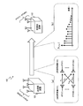
- FIG. 1 shows an example of a wireless communication system 100 according to this embodiment.
- the wireless communication system 100 includes a transmitting station apparatus 101 having a plurality of (Nt: an integer of Nt ⁇ 2) antennas ATt (1) to an antenna ATt (Nt) and a plurality of (Nr: an integer of Nr ⁇ 2) antennas. From ATr (1) to receiving station apparatus 102 having antenna ATr (Nr).
- Nt an integer of Nt ⁇ 2
- Nr an integer of Nr ⁇ 2
- a case will be described in which the single receiving station apparatus 102 includes a plurality of antennas ATr in the single-user MIMO wireless communication system 100.
- a plurality of receiving stations are provided in a multi-user MIMO wireless communication system. The same applies to the case where the device is equipped with one or more antennas.
- the wireless communication system 100 performs wireless communication between a transmitting station device 101 and a receiving station device 102 by a wideband single carrier MIMO method using a plurality of antennas.
- a plurality of delayed waves with different delay times such as multipaths exist, and frequency selective fading occurs. Therefore, it is necessary to suppress inter-antenna interference (IAI) and inter-symbol interference (ISI) due to channel characteristics.
- IAI inter-antenna interference
- ISI inter-symbol interference
- h 11 is provided between the antenna ATt (1) and the antenna ATr (1)
- h Nr1 is provided between the antenna ATt (1) and the antenna ATr (Nr)
- the antenna ATt ( h 1NT between Nt) and an antenna ATr (1) is IAI whose elements h NrNt occurs between the antenna ATt and (Nt) and antenna ATr (Nr).
- ISI inter-symbol interference
- the wireless communication system 100 performs processing for equalizing inter-antenna interference (IAI) and processing for equalizing inter-symbol interference (ISI) due to channel characteristics while suppressing processing delay. It has a function to perform at the same time.
- IAI inter-antenna interference
- ISI inter-symbol interference
- FIG. 2 shows an example of the transmitting station apparatus 101 and the receiving station apparatus 102 according to this embodiment.
- transmitting station apparatus 101 includes information bit generating section 201, data signal modulating section 202, training signal generating section 203, linear equalizing section 204, transmitting signal converting section 205, receiving signal converting section 206 and antenna ATt (1 ) To antenna ATt (Nt).
- receiving station apparatus 102 has Nr antennas from antenna ATr (1) to antenna ATr (Nr), received signal conversion section 301, coefficient estimation section 302, data signal demodulation section 303, information bit detection section. It has 304 and a transmission signal converter 305.
- the information bit generation unit 201 generates data information bits to be transmitted to the receiving station device 102.
- the data information bit is a bit string corresponding to, for example, a data signal input from the outside (not shown), a data signal generated internally, or the like.
- the information bit generation unit 201 may have an error correction coding function for generating an error correction code at a predetermined coding rate, an interleave function, or the like.
- the data signal modulator 202 outputs a data signal S (n) obtained by modulating the bit string output by the information bit generator 201 by a predetermined modulation method (for example, quadrature amplitude modulation (QAM: Quadrature Amplitude Modulation)).
- a predetermined modulation method for example, quadrature amplitude modulation (QAM: Quadrature Amplitude Modulation)
- the bit string output by the information bit generation unit 201 is divided into a plurality of streams according to the number of antennas ATt, and the modulated data signal S (n) is output for each stream.
- the data signal modulator 202 is provided for each stream.
- the training signal generation unit 203 generates a training signal for estimating a channel impulse response (CIR).
- the training signal is a predetermined signal in which predetermined information such as a preamble for signal detection (eg, a specific pattern such as an alternating pattern of “01”) is modulated by a modulation method such as PSK (Phase Shift Keying) that is less susceptible to interference. Yes, and is used by the receiving station apparatus 102 to estimate the CIR.
- PSK Phase Shift Keying
- the linear equalization unit 204 holds the data signal output from the data signal modulation unit 202, has a delay tap that shifts at regular time intervals, and calculates the sum of the signals obtained by multiplying the signals of the respective delay taps by a predetermined tap coefficient.
- This is a transversal type filter for output.
- the tap coefficient is a coefficient for removing the IAI and ISI calculated based on the CIR estimated by the receiving station apparatus 102.
- the linear equalization unit 204 performs linear equalization processing for removing IAI and ISI, and simultaneously performs transmission beam forming and equalization processing.
- the linear equalization unit 204 outputs the training signal output from the training signal generation unit 203 as it is without performing linear equalization processing.
- the transmission signal conversion unit 205 frequency-converts the data signal or training signal output by the linear equalization unit 204 into a high-frequency transmission signal for transmission from the antenna ATt. For example, the transmission signal conversion unit 205 up-converts the data signal or training signal in the 20 MHz band into a high frequency signal in the 5 GHz band, and sends it out from the antenna ATt.
- each of the streams divided into a plurality of streams is converted into a high frequency signal and sent from each of the antennas ATt (1) to ATt (Nt).
- the reception signal conversion unit 206 frequency-converts a high-frequency reception signal received by each of the antennas ATt (1) to ATt (Nt) into a low-frequency baseband signal. For example, the reception signal converter 206 down-converts a high frequency signal in the 5 GHz band and outputs a base band signal in the 20 MHz band.
- the reception signal conversion unit 206 receives a reception signal including information such as tap coefficients and CIR from the reception station device 102, converts the reception signal into a baseband signal, and outputs the baseband signal to the linear equalization unit 204.
- the function of the demodulation unit that demodulates information such as tap coefficients from the baseband signal may be included in the reception signal conversion unit 206 or the linear equalization unit 204.
- the transmitting station device 101 can transmit to the receiving station device 102 a transmission signal from which IAI and ISI have been removed at the same time.
- the antenna ATr has Nr transmitting / receiving antennas from the antenna ATr (1) to the antenna ATr (N r ) and transmits a high frequency signal output from a transmission signal conversion unit 305 described later as an electromagnetic wave. Radiates into space as. Alternatively, the antenna ATr converts an electromagnetic wave in space transmitted from the transmitting station device 101 into a high frequency signal.
- the reception signal conversion unit 301 like the reception signal conversion unit 206 of the transmission station device 101, frequency-converts the high frequency signal received by the antenna ATr into a baseband signal.
- the reception signal conversion unit 301 outputs the training signal received from the transmission station device 101 to the coefficient estimation unit 302, and outputs the data signal S ⁇ (n) received from the transmission station device 101 to the data signal demodulation unit 303.
- the reception signal conversion unit 301 frequency-converts a high frequency signal received from each of the antennas ATr (1) to ATr (Nr) into a baseband signal.
- the coefficient estimating unit 302 estimates the CIR from the training signal transmitted from the transmitting station apparatus 101, and the linear equalizing section 204 of the transmitting station apparatus 101 performs transmission beamforming and equalization processing for simultaneously removing IAI and ISI. Calculate the tap coefficient of.
- the coefficient estimator 302 may include a mechanism for adaptively controlling the error signal by calculating the error signal from the data signal instead of the training signal.
- the coefficient estimation unit 302 may be provided on the transmitting station device 101 side. In this case, the coefficient estimation unit 302 performs the process of estimating the CIR, transmits the estimated CIR information to the transmitting station device 101 side, and the transmitting station device 101 side determines the tap coefficient.
- the data signal demodulation unit 303 demodulates the data signal S ⁇ (n) output by the reception signal conversion unit 301 into information bits and outputs a bit string.
- the reception signal converter 301 outputs the data signals S ⁇ (n) of a plurality of streams according to the number of antennas ATr, and the data signal demodulator 303 demodulates the data signals S ⁇ (n) of each stream. To do.
- the data signal demodulation unit 303 outputs to the information bit detection unit 304 a bit string obtained by combining the bit strings divided into a plurality of streams on the transmitting station apparatus 101 side.
- the data signal demodulation unit 306 may include an error correction decoding function and a deinterleave function according to the function of the transmitting station device 101 side.
- the information bit detection unit 304 outputs received data obtained by converting the bit string output by the data signal demodulation unit 303 into digital data.
- the error correction decoding function and the deinterleave function may be performed on the information bit detection unit 304 side.
- the transmission signal conversion unit 305 converts the information output by the coefficient estimation unit 302 into a high frequency signal and sends it out from the antenna ATt.
- the CIR information and the tap coefficient information estimated by the coefficient estimation unit 302 are transmitted from the antenna ATt to the transmitting station device 101 side.
- the transmission signal conversion unit 305 or the coefficient estimation unit 302 may have the function of the modulation unit that modulates tap coefficient information into a baseband signal.
- the receiving station device 102 estimates the CIR from the training signal transmitted by the transmitting station device 101, calculates the tap coefficient for simultaneously removing IAI and ISI from the estimated CIR, and calculates the tap coefficient. 101 can be notified.
- the wireless communication system 100 can suppress the processing delay in single-carrier MIMO transmission, and simultaneously perform transmission beamforming and equalization processing to simultaneously remove IAI and ISI.
- FIG. 3 shows a signal flow in the case of 2 ⁇ 2 MIMO.
- the transmission signal S 1 (n) and the transmission signal S 2 (n) of two streams are transmitted with the transmission signal output from the data signal modulation unit 202 as S (n). It
- the linear equalization unit 204 multiplies the transmission signal S (n) by a tap coefficient W (z) for simultaneously removing IAI and ISI.
- the linear equalizer 204 has four linear equalizers 250-11, a linear equalizer 250-12, a linear equalizer 250-21, and a linear equalizer 250-22.
- the transmission signal S 1 (n) has tap coefficients W 11, n (z)
- the transmission signal S 2 (n) has tap coefficients W 12, n. (z)
- the transmission signal S 1 (n) has tap coefficients W 21, n (z)
- the transmission signal S 2 (n) has tap coefficients.
- the tap coefficient W 11, n (z), the tap coefficient W 12, n (z), the tap coefficient W 21, n (z) and the tap coefficient W 22, n (z) are delays provided in the time axis direction. It has a number of taps plus one coefficient. Then, a signal obtained by adding the signal multiplied by the tap coefficient W 11, n (z) and the signal multiplied by the tap coefficient W 12, n (z) is transmitted from the antenna ATt (1). Similarly, a signal obtained by adding the signal multiplied by the tap coefficient W 21, n (z) and the signal multiplied by the tap coefficient W 22, n (z) is transmitted from the antenna ATt (2).
- the radio signal transmitted from the antenna ATt (1) and the antenna ATt (2) is received by the antenna ATr (1) and the antenna ATr (2) of the receiving station device 102.
- the radio signal is affected by frequency selective fading in a communication path between the antennas ATt (1) and ATt (2) and the antennas ATr (1) and ATr (2).
- a reception signal S ⁇ (n) is obtained in which the additional noise N (n) due to the receiving circuit or the like is added to the signals received by the antenna ATr (1) and the antenna ATr (2).
- the additional noise n 1 (n) is added to the signal received by the antenna ATr (1) and the additional noise n 2 (n) is added to the signal received by the antenna ATr (2).
- the signal S 1 ⁇ (n) and the received signal S 2 ⁇ (n) are respectively obtained.
- the channel impulse response (CIR) is H (z)
- the tap coefficient is W (z)
- the additive noise is N (n)
- the relation between the transmission signal S (n) and the reception signal S ⁇ (n) is , Can be expressed by the following formula.
- Equation (1) the channel impulse response H (z) is expressed by the following equation.
- the tap coefficient W (z) is expressed by the following equation.
- the channel impulse response H (z) can be expressed by the following equation.
- the channel impulse response H (z) can be expressed by the following equation.
- H 1 is represented by the following equation according to the number of delayed waves.
- the tap coefficient W can be expressed by the following equation.
- W norm obtained by normalizing the tap coefficient W in order to keep the transmission power constant can be expressed by the following equation.
- the wireless communication system 100 can calculate the tap coefficient W (z) to be set in the linear equalization unit 204 in order to simultaneously remove the inter-antenna interference and the inter-symbol interference. .
- FIG. 4 shows an example of the linear equalization unit 204 according to this embodiment.
- the linear equalization unit 204 shown in FIG. 4 corresponds to the 2 ⁇ 2 MIMO explained in FIG.
- the linear equalizer 250-11 has N (N is a positive integer) delay taps Z ⁇ 1 , and each time the delay taps Z ⁇ 1 are passed, a predetermined time Td ( Delay (for example, symbol interval). Then, the input transmission signal S 1 (n) and the output signal of each delay tap Z ⁇ 1 are multiplied by the tap coefficient w 11,0 (z) to the tap coefficient w 11, N (z), respectively. The sum of the respective values of is output from the linear equalizer 250-11.
- N is a positive integer
- Td Delay
- the linear equalizer 250-12 inputs the transmission coefficient S 2 (n) and the output signal of each delay tap Z ⁇ 1 from the tap coefficient w 12,0 (z) to the tap coefficient w 12, N (z) is multiplied and the sum of the multiplied values is output from the linear equalizer 250-12. Then, the output signal of linear equalizer 250-11 and the output signal of linear equalizer 250-12 are added and transmitted from antenna ATt (1). Note that in FIG. 4, the block of the transmission signal conversion unit 205 between the linear equalization unit 204 and the antenna ATt (1) described in FIG. 1 is omitted.
- the linear equalizer 250-21 has N delay taps Z ⁇ 1 and delays each time passing through the delay tap Z ⁇ 1 by a predetermined time Td. Then, the input transmission signal S 1 (n) and the output signal of each delay tap Z ⁇ 1 are multiplied by the tap coefficient w 21,0 (z) to the tap coefficient w 21, N (z), respectively. The sum of the respective values of is output from the linear equalizer 250-21. Similarly, the linear equalizer 250-22 receives the input transmission signal S 2 (n) and the output signal of each delay tap Z ⁇ 1 from the tap coefficient w 22,0 (z) to the tap coefficient w 22 ,, respectively .
- N (z) is multiplied, and the sum of the multiplied values is output from the linear equalizer 250-22. Then, the output signal of linear equalizer 250-21 and the output signal of linear equalizer 250-22 are added and transmitted from antenna ATt (2). Note that, in FIG. 4, the block of the transmission signal conversion unit 205 described in FIG. 1 is omitted.
- the linear equalization unit 204 performs linear equalization processing using the tap coefficient W (z) on the transmission signal S 1 (n) and the transmission signal S 2 (n), ISI can be removed at the same time.
- the delay time involved in the processing is (delay tap interval) ⁇ (number of delay taps).
- the number N of delay taps is set so that the delay time (N ⁇ Td) due to the N delay taps and the maximum delay time Tdmax in the communication path satisfy the expression of Tdmax ⁇ (N ⁇ Td). Is desirable.
- the maximum delay time Tdmax in the communication path corresponds to, for example, the time length of the CP added to each block in the conventional technique of processing in block units. That is, in the wireless communication system 100 according to the present embodiment, the inter-antenna interference and the inter-symbol interference can be removed with only the processing delay of the conventional CP time length.
- FIG. 5 shows an example of the delay time of the wireless communication system 100 according to this embodiment.
- the linear equalization unit 204 corresponds to any of the four linear equalizers of the linear equalizer 250-11 to the linear equalizer 250-22 described in FIG. S 1 (n) and the output signal of each delay tap Z ⁇ 1 are multiplied by N tap coefficients (w 0 (z) to w N (z)), respectively, and the sum of each value after multiplication is obtained. It is output from the linear equalization unit 204.
- the delay time of one tap is Td and the number of taps is N
- the transmission signal S 1 (n) input to the linear equalization unit 204 is held in the delay tap Z ⁇ 1 for each tap and the time is kept.
- the data is transferred in the axial direction by the bucket relay method every Td time.
- the signal one tap before the transmission signal S 1 (n) is S 1 (n ⁇ 1)
- the signal N taps before is S 1 (n ⁇ N). Therefore, the delay time until the transmission signal S 1 (n) input to the linear equalization unit 204 passes through the N delay taps Z ⁇ 1 and is output from the linear equalization unit 204 is (Td ⁇ N). Become.
- FIG. 6 shows a wireless communication system 900 of a comparative example.
- the wireless communication system 900 includes a transmitting station device 901 and a receiving station device 902.
- the wireless communication system 900 shown in FIG. 6 shows an example of 2 ⁇ 2 MIMO and transmits two streams of a transmission signal S 1 (n) and a transmission signal S 2 (n).
- the transmitting station apparatus 901 includes a transmission beam forming unit 911 that forms a transmission beam to remove IAI and ISI from the transmission signal S 1 (n) and the transmission signal S 2 (n), and a transmission beam forming unit 911. It has a CP adding section 912 (1) and a CP adding section 912 (2) for adding a CP to block the signal output from the forming section 911. Then, the transmission signal with the CP added by the CP addition unit 912 (1) is transmitted from the antenna ATt (1), and the transmission signal with the CP added by the CP addition unit 912 (2) is transmitted from the antenna ATt (2). To be done.
- the receiving station device 902 receives the radio signal transmitted from the transmitting station device 901 at the antenna ATr (1) and the antenna ATr (2). Then, the CP of the signal received by the antenna ATr (1) is removed by the CP removing unit 921 (1), and the received signal S ⁇ 1 (n) is output. Similarly, the CP of the signal received by the antenna ATr (2) is removed by the CP removing unit 921 (2), and the received signal S ⁇ 2 (n) is output.
- blocks such as a modulation unit, a demodulation unit, a transmission signal conversion unit, and a reception signal conversion unit are omitted.
- FIG. 7 shows an example of the delay time of the wireless communication system 900 of the comparative example.
- the transmission signal S (n) transmission signal S 1 (n) or transmission signal S 2 (n) described in FIG. 6, the output signal of the transmission beam forming unit 911, and the CP addition unit 912 (CP
- the output signal of the addition unit 912 (1) or the CP addition unit 912 (2) is shown with the horizontal axis as time.
- the transmission signal S (n) of the transmission beam forming unit 911 is such that a plurality of symbol data is transmitted in block units like data block 1 and data block 2. Then, the transmission beam forming unit 911 performs the processing of removing the IAI and ISI and forming the transmission beam in units of data blocks. Therefore, the output signal of the transmission beam forming unit 911 is one block larger than the transmission signal S (n). Delay by minutes. Further, the CP adding unit 912 performs a process of copying a part of the end of the data block to the beginning and adding it. As a result, the output signal of CP adding section 912 is delayed from the output signal of transmission beam forming section 911 by the time of one block. In the example of FIG. 7, the data block 1 and the data block 2 of the transmission signal S (n) are delayed by one block in the transmission beam forming section 911 and output, and further delayed by one block in the CP adding section 912. It is being output.
- a processing delay of at least two blocks occurs in order to remove IAI and ISI in block units.
- FIG. 8 shows a processing example of the wireless communication system 100 according to the present embodiment. The process shown in FIG. 8 is executed by each unit of the transmitting station device 101 and the receiving station device 102 shown in FIG.
- Step S101 In the transmission station device 101, the training signal generation unit 203 generates a training signal for estimating the CIR, and the transmission signal conversion unit 205 transmits the training signal from the antenna ATt.
- Step S102 In the receiving station device 102, the coefficient estimating unit 302 receives the training signal transmitted in step S101 and estimates the CIR.
- Step S103 In the receiving station device 102, the coefficient estimating unit 302 calculates the tap coefficient based on the CIR estimated in step S102.
- Step S104 The receiving station device 102 transmits the tap coefficient calculated in step S103 to the transmitting station device 101.
- Step S105 The transmitting station device 101 receives the tap coefficient transmitted from the receiving station device 102 in step S104.
- Step S106 In the transmission station device 101, the linear equalization unit 204 sets the tap coefficient received in Step S105 in the linear equalization unit 204.
- Step S107 In the transmission station device 101, the linear equalization unit 204 starts transmitting a data signal from which IAI and ISI have been removed using the tap coefficient set in step S106.
- Step S108 The receiving station device 102 starts receiving the data signal from which IAI and ISI have been removed.
- FIG. 9 shows an example of a transmitting station apparatus and a receiving station apparatus according to another embodiment.
- a wireless communication system 100a according to this embodiment includes a transmitting station device 101a and a receiving station device 102a.
- the difference between the wireless communication system 100 described in FIG. 2 and the wireless communication system 100a illustrated in FIG. 9 is that the process of estimating the tap coefficient is performed on the transmitting station device 101a side instead of the receiving station device 102a side. is there.
- the transmitting station device 101 a includes a coefficient calculation unit 401 between the received signal conversion unit 206 and the linear equalization unit 204. Further, the receiving station device 102a has a CIR estimating unit 501 instead of the coefficient estimating unit 302 of the receiving station device 102 of FIG.
- the CIR estimation unit 501 of the reception station device 102a receives the training signal transmitted from the transmission station device 101a, estimates the CIR, and transmits the CIR information from the transmission signal conversion unit 305 and the antenna ATr. .
- the coefficient calculation unit 401 of the transmission station device 101a receives the CIR information transmitted from the reception station device 102a, calculates the tap coefficient used in the linear equalization unit 204, and sets it in the linear equalization unit 204. .
- the wireless communication system 100a estimates the CIR from the training signal transmitted by the transmission station device 101, and the estimated CIR is the same as the wireless communication system 100 according to the previous embodiment.
- a tap coefficient for removing IAI and ISI at the same time can be determined.
- the wireless communication system 100a can suppress the processing delay in the single-carrier MIMO transmission and simultaneously remove the IAI and ISI by making the transmission beamforming and the equalization processing compatible.
- FIG. 10 shows a processing example of the wireless communication system 100a according to another embodiment. The processing illustrated in FIG. 10 is executed by each unit of the transmission station device 101 and the reception station device 102 illustrated in FIG. Note that, in FIG. 10, steps having the same reference numerals as those in FIG. 8 described in the above embodiment perform the same processing as in FIG. 8.
- Steps S101 and S102 perform the same processing as that of FIG. 8, and the receiving station device 102a receives the training signal transmitted from the transmitting station device 101a and estimates the CIR.
- Step S201 The receiving station device 102a transmits the CIR estimated at step S101 to the transmitting station device 101a.
- Step S202 The transmitting station device 101a receives the CIR transmitted from the receiving station device 102a in step S201.
- Step S203 In the transmission station device 101a, the coefficient calculation unit 401 calculates the tap coefficient based on the CIR received in step S202.
- step S106 to step S108 the same processing as the processing in FIG. 8 is performed, and the transmitting station device 101a sets the tap coefficient calculated in step S203 in the linear equalization unit 204. Then, the transmitting station device 101a starts transmitting the data signal from which the IAI and ISI have been removed, and the receiving station device 102a starts receiving the data signal.
- the receiving station device 102a estimates the CIR from the training signal transmitted by the transmitting station device 101a, and the transmitting station device 101a determines the tap coefficient for simultaneously removing IAI and ISI from the estimated CIR. Then, communication can be performed.
- the wireless communication system, the wireless communication method, the transmitting station apparatus, and the receiving station apparatus according to the present invention suppress transmission delay in single carrier MIMO transmission and perform transmission beamforming and equalization. It is possible to remove IAI and ISI at the same time by being compatible with the treatment.
Landscapes
- Engineering & Computer Science (AREA)
- Computer Networks & Wireless Communication (AREA)
- Signal Processing (AREA)
- Power Engineering (AREA)
- Radio Transmission System (AREA)
- Cable Transmission Systems, Equalization Of Radio And Reduction Of Echo (AREA)
Abstract
本発明では、送信局装置は、送信データを分割した各々のストリームを変調して複数の第1データ信号を生成する複数の変調部と、トレーニング信号生成部と、アンテナ間干渉およびシンボル間干渉を除去するタップ係数を用いて第1データ信号の線形等化を行い、送信ビーム形成と等化処理とを同時に行った第2データ信号を出力する線形等化部と、トレーニング信号または第2データ信号を受信局装置に送信し、タップ係数を受信局装置から受信する複数の送信局通信部とを備え、受信局装置は、トレーニング信号から通信路インパルス応答を推定し、通信路インパルス応答に基づいて、タップ係数を算出する係数推定部と、第2データ信号またはトレーニング信号を受信し、係数推定部が算出したタップ係数を送信局装置に送信する受信局通信部とを備える。
Description
本発明は、シングルキャリアMIMO(Multiple-Input Multiple-Output)伝送を行う無線通信システムにおいて、アンテナ間干渉とシンボル間干渉とを抑制する技術に関する。
周波数選択性のフェージングがある通信環境下で広帯域のシングルキャリアMIMO伝送を行う際には、複数のアンテナの空間的な広がりにより生じるIAI(Inter-Antenna Interference:アンテナ間干渉)と、通信路特性の時間的な広がりにより生じるISI(Inter-Symbol Interference:シンボル間干渉)を抑制するための処理が必要となる。ここで、MIMO伝送される各信号ストリームを時間方向でブロック化することにより、通信路特性を示すCIR(Channel Impulse Response:通信路インパルス応答)行列に時間および空間情報を含めることができる。そこで、従来技術では、CP(Cyclic Prefix:巡回プレフィックス)を付加してMIMO伝送される信号をブロック化し、ブロック単位で送信ビーム形成を行うことにより、IAIおよびISIを除去している(例えば、非特許文献1参照)。
S.Yoshioka,S.Kumagai,and F.Adachi,"Single-carrier multi-user MIMO downlink with time-domain Tomlinson-harashima precoding,"IEICE Trans.Commun.,vol.E99-B,Feb.2016.
ところが、従来技術では、送信ビーム形成のためにブロック単位で行列演算を行い、各ブロックの後尾の一部のデータをコピーして各ブロックの先頭にCPとして付加する処理を行うので、ブロック単位での行列乗算時やCPの付加時に、それぞれ1ブロック長分の処理遅延が発生するという問題がある。
本発明は、シングルキャリアMIMO伝送における処理遅延を抑制しつつ、送信ビーム形成と等化処理とを両立してIAIおよびISIを同時に除去できる無線通信システム、無線通信方法、送信局装置および受信局装置を提供することを目的とする。
第1の発明は、送信局装置と単数または複数の受信局装置との間でシングルキャリアMIMO伝送を行う無線通信システムにおいて、前記送信局装置は、送信データを複数のストリームに分割した各々のストリームを変調して複数の第1データ信号を生成する複数の変調部と、既知のトレーニング信号を生成するトレーニング信号生成部と、アンテナ間干渉およびシンボル間干渉を除去するタップ係数を用いて複数の前記第1データ信号の線形等化を行い、送信ビーム形成と等化処理とを同時に行った複数の第2データ信号を出力する線形等化部と、前記トレーニング信号または複数の前記第2データ信号を前記受信局装置に送信し、前記タップ係数を前記受信局装置から受信する複数の送信局通信部とを備え、前記受信局装置は、前記送信局装置が送信した前記トレーニング信号から通信路インパルス応答を推定し、前記通信路インパルス応答に基づいて、前記送信局装置の前記線形等化部で用いる前記タップ係数を算出する係数推定部と、前記送信局装置が送信する前記第2データ信号または前記トレーニング信号を受信し、前記係数推定部が算出した前記タップ係数を前記送信局装置に送信する受信局通信部とを備えることを特徴とする。
第2の発明は、送信局装置と単数または複数の受信局装置との間でシングルキャリアMIMO伝送を行う無線通信システムにおいて、前記送信局装置は、送信データを複数のストリームに分割した各々のストリームを変調して複数の第1データ信号を生成する複数の変調部と、既知のトレーニング信号を生成するトレーニング信号生成部と、アンテナ間干渉およびシンボル間干渉を除去するタップ係数を用いて複数の前記第1データ信号の線形等化を行い、送信ビーム形成と等化処理とを同時に行った複数の第2データ信号を出力する線形等化部と、前記受信局装置から受信する通信路インパルス応答に基づいて、前記タップ係数を算出する係数算出部と、前記トレーニング信号または複数の前記第2データ信号を前記受信局装置に送信し、前記通信路インパルス応答を前記受信局装置から受信する複数の送信局通信部とを備え、前記受信局装置は、前記送信局装置が送信した前記トレーニング信号から前記通信路インパルス応答を推定する推定部と、前記送信局装置が送信する前記第2データ信号または前記トレーニング信号を受信し、前記推定部が推定した前記通信路インパルス応答を前記送信局装置に送信する受信局通信部とを備えることを特徴とする。
第3の発明は、送信局装置と単数または複数の受信局装置との間でシングルキャリアMIMO伝送を行う無線通信システムにおける無線通信方法であって、前記送信局装置は、送信データを複数のストリームに分割した各々のストリームを変調して複数の第1データ信号を生成する変調処理と、既知のトレーニング信号を生成するトレーニング信号生成処理と、アンテナ間干渉およびシンボル間干渉を除去するタップ係数を用いて複数の前記第1データ信号の線形等化を行い、送信ビーム形成と等化処理とを同時に行った複数の第2データ信号を出力する線形等化処理と、前記トレーニング信号または複数の前記第2データ信号を前記受信局装置に送信し、前記タップ係数を前記受信局装置から受信する送信局通信処理とを実行し、前記受信局装置は、前記送信局装置が送信した前記トレーニング信号から通信路インパルス応答を推定し、前記通信路インパルス応答に基づいて、前記送信局装置の前記線形等化処理で用いる前記タップ係数を算出する係数推定処理と、前記送信局装置が送信する前記第2データ信号または前記トレーニング信号を受信し、前記係数推定処理により算出した前記タップ係数を前記送信局装置に送信する受信局通信処理とを実行することを特徴とする。
第4の発明は、送信局装置と単数または複数の受信局装置との間でシングルキャリアMIMO伝送を行う無線通信システムにおける無線通信方法であって、前記送信局装置は、送信データを複数のストリームに分割した各々のストリームを変調して複数の第1データ信号を生成する変調処理と、既知のトレーニング信号を生成するトレーニング信号生成処理と、アンテナ間干渉およびシンボル間干渉を除去するタップ係数を用いて複数の前記第1データ信号の線形等化を行い、送信ビーム形成と等化処理とを同時に行った複数の第2データ信号を出力する線形等化処理と、前記受信局装置から受信する通信路インパルス応答に基づいて、前記タップ係数を算出する係数算出処理と、前記トレーニング信号または複数の前記第2データ信号を前記受信局装置に送信し、前記通信路インパルス応答を前記受信局装置から受信する送信局通信処理とを実行し、前記受信局装置は、前記送信局装置が送信した前記トレーニング信号から前記通信路インパルス応答を推定する推定処理と、前記送信局装置が送信する前記第2データ信号または前記トレーニング信号を受信し、前記推定処理により推定した前記通信路インパルス応答を前記送信局装置に送信する受信局通信処理とを実行することを特徴とする。
第5の発明は、単数または複数の受信局装置との間でシングルキャリアMIMO伝送を行う送信局装置において、送信データを複数のストリームに分割した各々のストリームを変調して複数の第1データ信号を生成する複数の変調部と、既知のトレーニング信号を生成するトレーニング信号生成部と、アンテナ間干渉およびシンボル間干渉を除去するタップ係数を用いて複数の前記第1データ信号の線形等化を行い、送信ビーム形成と等化処理とを同時に行った複数の第2データ信号を出力する線形等化部と、前記トレーニング信号または複数の前記第2データ信号を前記受信局装置に送信し、前記タップ係数を前記受信局装置から受信する複数の送信局通信部とを備えることを特徴とする。
第6の発明は、単数または複数の受信局装置との間でシングルキャリアMIMO伝送を行う送信局装置において、送信データを複数のストリームに分割した各々のストリームを変調して複数の第1データ信号を生成する複数の変調部と、既知のトレーニング信号を生成するトレーニング信号生成部と、アンテナ間干渉およびシンボル間干渉を除去するタップ係数を用いて複数の前記第1データ信号の線形等化を行い、送信ビーム形成と等化処理とを同時に行った複数の第2データ信号を出力する線形等化部と、前記受信局装置から受信する通信路インパルス応答に基づいて、前記タップ係数を算出する係数算出部と、前記トレーニング信号または複数の前記第2データ信号を前記受信局装置に送信し、前記通信路インパルス応答を前記受信局装置から受信する複数の送信局通信部とを備えることを特徴とする。
第7の発明は、送信局装置との間でシングルキャリアMIMO伝送を行う受信局装置において、前記送信局装置が送信したトレーニング信号から通信路インパルス応答を推定し、前記通信路インパルス応答に基づいて、前記送信局装置の線形等化部で用いるタップ係数を算出する係数推定部と、前記送信局装置が送信するデータ信号または前記トレーニング信号を受信し、前記係数推定部が算出した前記タップ係数を前記送信局装置に送信する受信局通信部とを備えることを特徴とする。
第8の発明は、送信局装置との間でシングルキャリアMIMO伝送を行う受信局装置において、前記送信局装置が送信したトレーニング信号から前記通信路インパルス応答を推定する推定部と、前記送信局装置が送信するデータ信号または前記トレーニング信号を受信し、前記推定部が推定した前記通信路インパルス応答を前記送信局装置に送信する受信局通信部とを備えることを特徴とする。
本発明に係る無線通信システム、無線通信方法、送信局装置および受信局装置は、シングルキャリアMIMO伝送における処理遅延を抑制しつつ、送信ビーム形成と等化処理とを両立してIAIおよびISIを同時に除去することができる。
以下、図面を参照して本発明に係る無線通信システム、無線通信方法、送信局装置および受信局装置の実施形態について説明する。
図1は、本実施形態に係る無線通信システム100の一例を示す。無線通信システム100は、複数(Nt個:Nt≧2の整数)のアンテナATt(1)からアンテナATt(Nt)を有する送信局装置101と、複数(Nr個:Nr≧2の整数)のアンテナATr(1)からアンテナATr(Nr)を有する受信局装置102とを備える。ここで、本実施形態では、シングルユーザMIMOの無線通信システム100において、単数の受信局装置102が複数のアンテナATrを備える場合について説明するが、マルチユーザMIMOの無線通信システムにおいて、複数の受信局装置が単数または複数のアンテナを備える場合についても同様に適用可能である。なお、以降の説明において、送信局装置101のアンテナATt(1)からアンテナATt(Nt)に共通の説明を行う場合は符号末尾の(番号)を省略してアンテナATtと表記し、特定のアンテナを指す場合は符号末尾に(番号)を付加して例えばアンテナATt(1)のように表記する。受信局装置102のアンテナATr(1)からアンテナATr(Nr)についても同様に表記する。
本実施形態に係る無線通信システム100は、送信局装置101と受信局装置102の間で複数のアンテナを用いた広帯域のシングルキャリアMIMO方式による無線通信を行う。ここで、送信局装置101と受信局装置102の間では、マルチパスなど遅延時間が異なる複数の遅延波が存在し、周波数選択性のフェージングが生じる。このため、アンテナ間干渉(IAI)と通信路特性によるシンボル間干渉(ISI)とを抑制する必要がある。例えば、図1(a)に示すように、送信局装置101のNt個のアンテナと、受信局装置102のNr個のアンテナとの間で空間的な広がりによるアンテナ間干渉(IAI)が生じる。図1(a)の例では、アンテナATt(1)とアンテナATr(1)との間にはh11、アンテナATt(1)とアンテナATr(Nr)との間にはhNr1、アンテナATt(Nt)とアンテナATr(1)との間にはh1Nt、アンテナATt(Nt)とアンテナATr(Nr)との間にはhNrNtを要素とするIAIが生じる。また、図1(b)に示すように、送信局装置101と受信局装置102のそれぞれのアンテナ間で送受信される信号には、時間的な広がりによるシンボル間干渉(ISI)が生じる。図1(b)の例では、アンテナATt(nt)とアンテナATr(nr)との間で送受信される信号にはhnrnt,lを要素とする時間l方向にISIが生じる。そこで、本実施形態に係る無線通信システム100は、処理遅延を抑制しつつ、アンテナ間干渉(IAI)を等化する処理と、通信路特性によるシンボル間干渉(ISI)を等化する処理とを同時に行う機能を備えている。
図2は、本実施形態に係る送信局装置101および受信局装置102の一例を示す。図2において、送信局装置101は、情報ビット生成部201、データ信号変調部202、トレーニング信号生成部203、線形等化部204、送信信号変換部205、受信信号変換部206およびアンテナATt(1)からアンテナATt(Nt)のNt個のアンテナを有する。また、図2において、受信局装置102は、アンテナATr(1)からアンテナATr(Nr)のNr個のアンテナ、受信信号変換部301、係数推定部302、データ信号復調部303、情報ビット検出部304および送信信号変換部305を有する。
先ず、送信局装置101の構成について説明する。
情報ビット生成部201は、受信局装置102へ送信するデータ情報ビットを生成する。データ情報ビットは、例えば外部(不図示)から入力するデータ信号、内部で生成するデータ信号などに対応するビット列である。なお、情報ビット生成部201は、所定の符号化率で誤り訂正符号を生成する誤り訂正符号化機能やインターリーブ機能などを有してもよい。
データ信号変調部202は、情報ビット生成部201が出力するビット列を所定の変調方式(例えば直交振幅変調(QAM:Quadrature Amplitude Modulation)など)で変調したデータ信号S(n)を出力する。なお、本実施形態では、情報ビット生成部201が出力するビット列をアンテナATtの数に応じて複数のストリームに分割し、各々のストリーム毎に変調したデータ信号S(n)を出力するので、各ストリーム毎にデータ信号変調部202を有する。
トレーニング信号生成部203は、通信路インパルス応答(CIR)を推定するためのトレーニング信号を生成する。トレーニング信号は、信号検出用のプリアンブルなどの予め決められた情報(例えば”01”の交互パターン等の特定パターン)をPSK(Phase Shift Keying)など干渉を受けにくい変調方式で変調した所定の信号であり、受信局装置102でCIRを推定するために用いられる。なお、送信局装置101が送信するトレーニング信号の情報は、予め受信局装置102との間で既知である。
線形等化部204は、データ信号変調部202が出力するデータ信号を保持し、一定時間毎にシフトする遅延タップを有し、各遅延タップの信号に所定のタップ係数を乗算した信号の和を出力するトランスバーサル型のフィルタである。ここで、タップ係数は、受信局装置102が推定したCIRに基づいて算出したIAIおよびISIを除去するための係数である。線形等化部204は、IAIおよびISIを除去するための線形等化処理を行い、送信ビーム形成と等化処理とを同時に行う。なお、線形等化部204は、トレーニング信号生成部203が出力するトレーニング信号については、線形等化処理を行わずにそのまま出力する。
送信信号変換部205は、線形等化部204が出力するデータ信号またはトレーニング信号をアンテナATtから送出するための高周波の送信信号に周波数変換する。例えば、送信信号変換部205は、20MHz帯域のデータ信号またはトレーニング信号を5GHz帯の高周波信号にアップコンバートして、アンテナATtから送出する。ここで、複数のストリームに分割された各々のストリームは、それぞれ高周波信号に変換され、アンテナATt(1)からアンテナATt(Nt)のそれぞれから送出される。
受信信号変換部206は、アンテナATt(1)からアンテナATt(Nt)のそれぞれのアンテナにより受信された高周波の受信信号を低周波のベースバンド信号に周波数変換する。例えば、受信信号変換部206は、5GHz帯の高周波信号をダウンコンバートして20MHz帯域のベースバンド信号を出力する。ここで、本実施形態では、受信信号変換部206は、受信局装置102からタップ係数やCIRなどの情報を含む受信信号を受け取り、ベースバンド信号に変換して線形等化部204に出力する。なお、ベースバンド信号からタップ係数などの情報を復調する復調部の機能は、受信信号変換部206が有してもよいし、線形等化部204が有してもよい。
このようにして、送信局装置101は、IAIおよびISIを同時に除去した送信信号を受信局装置102へ送信することができる。
次に、図2に示す受信局装置102の構成について説明する。
アンテナATrは、図1で説明したように、アンテナATr(1)からアンテナATr(Nr)のNr個の送受信用のアンテナを有し、後述する送信信号変換部305が出力する高周波信号を電磁波として空間に放射する。或いは、アンテナATrは、送信局装置101から送信された空間上の電磁波を高周波信号に変換する。
受信信号変換部301は、送信局装置101の受信信号変換部206と同様に、アンテナATrが受信する高周波信号をベースバンド信号に周波数変換する。ここで、受信信号変換部301は、送信局装置101から受信するトレーニング信号を係数推定部302へ出力し、送信局装置101から受信するデータ信号S^(n)をデータ信号復調部303へ出力する。ここで、受信信号変換部301は、アンテナATr(1)からアンテナATr(Nr)のそれぞれから受信される高周波信号をベースバンド信号に周波数変換する。
係数推定部302は、送信局装置101から送信されるトレーニング信号からCIRを推定し、送信局装置101の線形等化部204でIAIおよびISIを同時に除去する送信ビーム形成と等化処理を行うためのタップ係数を算出する。なお、係数推定部302は、トレーニング信号ではなく、データ信号から誤差信号を算出して適応制御する機構を備えてもよい。また、係数推定部302は、送信局装置101側に備えてもよい。この場合、係数推定部302は、CIRを推定する処理を行い、推定したCIRの情報を送信局装置101側に送信し、送信局装置101側でタップ係数を決定する。
データ信号復調部303は、受信信号変換部301が出力するデータ信号S^(n)を情報ビットに復調し、ビット列を出力する。なお、受信信号変換部301は、アンテナATrの数に応じて複数のストリームのデータ信号S^(n)を出力し、データ信号復調部303は、ストリーム毎のデータ信号S^(n)を復調する。そして、データ信号復調部303は、送信局装置101側で複数のストリームに分割されたビット列を結合したビット列を情報ビット検出部304に出力する。なお、データ信号復調部306は、送信局装置101側の機能に応じて、誤り訂正復号機能やデインターリーブ機能を備えてもよい。
情報ビット検出部304は、データ信号復調部303が出力するビット列をデジタルデータに変換した受信データを出力する。なお、誤り訂正復号機能やデインターリーブ機能を情報ビット検出部304側で行ってもよい。
送信信号変換部305は、送信局装置101の送信信号変換部205と同様に、係数推定部302が出力する情報を高周波信号に変換してアンテナATtから送出する。例えば、本実施形態では、係数推定部302が推定したCIRの情報やタップ係数の情報などをアンテナATtから送信局装置101側に送信する。なお、タップ係数の情報をベースバンド信号に変調する変調部の機能は、送信信号変換部305が有してもよいし、係数推定部302が有してもよい。
このようにして、受信局装置102は、送信局装置101が送信するトレーニング信号からCIRを推定し、推定されたCIRからIAIおよびISIを同時に除去するためのタップ係数を算出して、送信局装置101に通知することができる。これにより、無線通信システム100は、シングルキャリアMIMO伝送における処理遅延を抑制しつつ、送信ビーム形成と等化処理とを両立してIAIおよびISIを同時に除去することができる。
図3は、2×2のMIMOの場合の信号の流れを示す。図3において、送信局装置101側では、データ信号変調部202が出力する送信信号をS(n)として、2つのストリームの送信信号S1(n)および送信信号S2(n)が送信される。
線形等化部204は、IAIおよびISIを同時に除去するためのタップ係数W(z)を送信信号S(n)に乗算する。ここで、線形等化部204は、4つの線形等化器250-11、線形等化器250-12、線形等化器250-21および線形等化器250-22を有する。線形等化器250-11では、送信信号S1(n)にタップ係数W11,n(z)、線形等化器250-12では、送信信号S2(n)にタップ係数W12,n(z)、線形等化器250-21では、送信信号S1(n)にタップ係数W21,n(z)、線形等化器250-22では、送信信号S2(n)にタップ係数W22,n(z)、をそれぞれ乗算する。ここで、タップ係数W11,n(z)、タップ係数W12,n(z)、タップ係数W21,n(z)およびタップ係数W22,n(z)は、時間軸方向に設ける遅延タップの数+1個の係数を有する。そして、タップ係数W11,n(z)が乗算された信号と、タップ係数W12,n(z)が乗算された信号とが加算された信号がアンテナATt(1)から送出される。同様に、タップ係数W21,n(z)が乗算された信号と、タップ係数W22,n(z)が乗算された信号とが加算された信号がアンテナATt(2)から送出される。
アンテナATt(1)およびアンテナATt(2)から送出された無線信号は、受信局装置102のアンテナATr(1)およびアンテナATr(2)で受信される。ここで、無線信号は、アンテナATt(1)およびアンテナATt(2)とアンテナATr(1)およびアンテナATr(2)との間の通信路において、周波数選択性のフェージングなどの影響を受ける。
受信局装置102側では、アンテナATr(1)およびアンテナATr(2)で受信された信号に受信回路などによる付加雑音N(n)が付加された受信信号S^(n)が得られる。図3の例では、アンテナATr(1)で受信された信号に付加雑音n1(n)、アンテナATr(2)で受信された信号に付加雑音n2(n)、がそれぞれ付加され、受信信号S1^(n)および受信信号S2^(n)がそれぞれ得られる。
ここで、通信路インパルス応答(CIR)をH(z)、タップ係数をW(z)、付加雑音をN(n)として、送信信号S(n)と受信信号S^(n)の関係は、下式で表すことができる。

式(1)において、通信路インパルス応答H(z)は、下式で表される。


また、式(1)において、タップ係数W(z)は、下式で表される。


次に、ZF(Zero Forcing)規範の場合の線形等化部204におけるタップ係数W(z)の一例について説明する。なお、下式の導出方法については後述する。

図3で説明した2×2のMIMOの場合、通信路インパルス応答H(z)は、次式で表すことができる。

また、通信路インパルス応答H(z)の逆行列は、次式で表すことができる。

同様に、Nr×NtのMIMOの場合(Nr≦Nt)、通信路インパルス応答H(z)は、次式で表すことができる。

ここで、Hlは、遅延波の数に応じて次式で表される。

また、通信路インパルス応答H(z)の逆行列は、次式で表すことができる。

次に、線形等化部204におけるタップ係数Wの導出方法について説明する。
先に説明した図3において、ZF規範のウェイト演算を行うと、付加雑音N(n)を無視するため、受信信号S^は、次式のようになる。

ここで、タップ係数Wは、次式で表すことができる。

(H+は疑似逆行列、HHはエルミート転置行列)
このとき、送信局装置101から送信される無線信号SRFは、次式のようになる。
このとき、送信局装置101から送信される無線信号SRFは、次式のようになる。

ここで、送信電力を一定にするために、タップ係数Wを正規化したWnormは、次式で表すことができる。

このようにして、本実施形態に係る無線通信システム100は、アンテナ間干渉およびシンボル間干渉を同時に除去するために線形等化部204に設定すべきタップ係数W(z)を算出することができる。
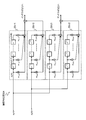
図4は、本実施形態に係る線形等化部204の一例を示す。なお、図4に示す線形等化部204は、図3で説明した2×2のMIMOに対応する。図4において、線形等化器250-11は、N個(Nは正の整数)の遅延タップZ-1を有し、遅延タップZ-1を通る度に予め決められた所定の時間Td(例えばシンボル間隔)だけ遅延する。そして、入力される送信信号S1(n)と各遅延タップZ-1の出力信号とにそれぞれタップ係数w11,0(z)からタップ係数w11,N(z)が乗算され、乗算後の各値の和が線形等化器250-11から出力される。同様に、線形等化器250-12は、入力される送信信号S2(n)と各遅延タップZ-1の出力信号とにそれぞれタップ係数w12,0(z)からタップ係数w12,N(z)が乗算され、乗算後の各値の和が線形等化器250-12から出力される。そして、線形等化器250-11の出力信号と線形等化器250-12の出力信号とが加算されてアンテナATt(1)から送信される。なお、図4では、図1で説明した線形等化部204とアンテナATt(1)との間の送信信号変換部205のブロックは省略されている。
同様に、図4において、線形等化器250-21は、N個の遅延タップZ-1を有し、遅延タップZ-1を通る度に予め決められた所定の時間Tdだけ遅延する。そして、入力される送信信号S1(n)と各遅延タップZ-1の出力信号とにそれぞれタップ係数w21,0(z)からタップ係数w21,N(z)が乗算され、乗算後の各値の和が線形等化器250-21から出力される。同様に、線形等化器250-22は、入力される送信信号S2(n)と各遅延タップZ-1の出力信号とにそれぞれタップ係数w22,0(z)からタップ係数w22,N(z)が乗算され、乗算後の各値の和が線形等化器250-22から出力される。そして、線形等化器250-21の出力信号と線形等化器250-22の出力信号とが加算されてアンテナATt(2)から送信される。なお、図4では、図1で説明した送信信号変換部205のブロックは省略されている。
このようにして、線形等化部204は、送信信号S1(n)および送信信号S2(n)に対して、タップ係数W(z)を用いた線形等化処理を行うので、IAIとISIとを同時に除去することができる。ここで、処理に伴う遅延時間は、(遅延タップの間隔)×(遅延タップの数)となる。なお、遅延タップの数Nは、N個の遅延タップによる遅延時間(N×Td)と通信路における最大の遅延時間Tdmaxとが、Tdmax≦(N×Td)の式を満たすように設定するのが望ましい。ここで、通信路における最大の遅延時間Tdmaxは、例えばブロック単位で処理する従来技術で各ブロックに付加するCPの時間長に相当する。つまり、本実施形態に係る無線通信システム100では、従来のCPの時間長程度の処理遅延だけで、アンテナ間干渉とシンボル間干渉とを除去することができる。
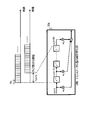
図5は、本実施形態に係る無線通信システム100の遅延時間の一例を示す。図5において、線形等化部204は、図4で説明した線形等化器250-11から線形等化器250-22の4つの線形等化器のいずれかに対応し、入力される送信信号S1(n)と各遅延タップZ-1の出力信号とに対してN個のタップ係数(w0(z)からwN(z))がそれぞれ乗算され、乗算後の各値の和が線形等化部204から出力される。ここで、1タップの遅延時間をTd、タップ数をNとすると、線形等化部204に入力される送信信号S1(n)は、1タップ毎に遅延タップZ-1に保持されながら時間軸方向にバケツリレー方式でTd時間毎に転送される。例えば送信信号S1(n)の1タップ前の信号はS1(n-1)、Nタップ前の信号はS1(n-N)となる。従って、線形等化部204に入力される送信信号S1(n)がN個の遅延タップZ-1を通り抜けて線形等化部204から出力されるまでの遅延時間は(Td×N)となる。
図6は、比較例の無線通信システム900を示す。無線通信システム900は、送信局装置901および受信局装置902を有する。ここで、図6に示した無線通信システム900は、2×2のMIMOの例を示し、送信信号S1(n)および送信信号S2(n)の2つのストリームを送信する。
図6において、送信局装置901は、送信信号S1(n)および送信信号S2(n)に対してIAIおよびISIを除去するための送信ビーム形成を行う送信ビーム形成部911と、送信ビーム形成部911が出力する信号をブロック化するためにCPを付加するCP付加部912(1)およびCP付加部912(2)を有する。そして、CP付加部912(1)でCPが付加された送信信号はアンテナATt(1)から送信され、CP付加部912(2)でCPが付加された送信信号はアンテナATt(2)から送信される。受信局装置902は、送信局装置901から送信される無線信号をアンテナATr(1)およびアンテナATr(2)で受信する。そして、アンテナATr(1)で受信された信号はCP除去部921(1)でCPが除去され、受信信号S^1(n)が出力される。同様に、アンテナATr(2)で受信された信号はCP除去部921(2)でCPが除去され、受信信号S^2(n)が出力される。ここで、図6において、変調部、復調部、送信信号変換部および受信信号変換部などの各ブロックは省略されている。
図7は、比較例の無線通信システム900の遅延時間の一例を示す。図7において、図6で説明した送信信号S(n)(送信信号S1(n)または送信信号S2(n))と、送信ビーム形成部911の出力信号と、CP付加部912(CP付加部912(1)またはCP付加部912(2))の出力信号とが横軸を時間としてそれぞれ示されている。
図7において、送信ビーム形成部911の送信信号S(n)は、データブロック1、データブロック2のように、複数のシンボルデータがブロック単位で送信される。そして、送信ビーム形成部911は、IAIおよびISIを除去して送信ビーム形成を行う処理をデータブロック単位で行うので、送信ビーム形成部911の出力信号は、送信信号S(n)よりも1ブロック分の時間だけ遅延する。さらに、CP付加部912は、データブロックの末尾の一部を先頭にコピーして付加する処理を行う。これにより、CP付加部912の出力信号は、送信ビーム形成部911の出力信号よりも1ブロック分の時間だけ遅延する。図7の例では、送信信号S(n)のデータブロック1およびデータブロック2は、送信ビーム形成部911で1ブロック分遅延して出力され、さらに、CP付加部912で1ブロック分遅延して出力されている。
このように、比較例の無線通信システム900では、ブロック単位でIAIおよびISIを除去するために少なくとも2ブロック分の処理遅延が生じる。
これに対して、図5で説明した本実施形態に係る無線通信システム100では、遅延タップ数分の遅延だけであり、例えば図7のCPの時間(CP1またはCP2の時間)程度の処理遅延でIAIおよびISIを除去することができる。
[無線通信システム100の処理方法]
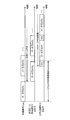
図8は、本実施形態に係る無線通信システム100の処理例を示す。なお、図8に示した処理は、図2に示した送信局装置101および受信局装置102の各部により実行される。
[無線通信システム100の処理方法]
図8は、本実施形態に係る無線通信システム100の処理例を示す。なお、図8に示した処理は、図2に示した送信局装置101および受信局装置102の各部により実行される。
ステップS101:送信局装置101において、トレーニング信号生成部203は、CIRを推定するためのトレーニング信号を生成し、送信信号変換部205によりアンテナATtから送信される。
ステップS102:受信局装置102において、係数推定部302は、ステップS101で送信されたトレーニング信号を受信してCIRを推定する。
ステップS103:受信局装置102において、係数推定部302は、ステップS102で推定されたCIRに基づいてタップ係数を算出する。
ステップS104:受信局装置102は、ステップS103で算出されたタップ係数を送信局装置101へ送信する。
ステップS105:送信局装置101は、ステップS104で受信局装置102から送信されたタップ係数を受信する。
ステップS106:送信局装置101において、線形等化部204は、ステップS105で受信したタップ係数を線形等化部204に設定する。
ステップS107:送信局装置101において、線形等化部204は、ステップS106で設定したタップ係数を用いてIAIおよびISIを除去したデータ信号の送信を開始する。
ステップS108:受信局装置102は、IAIおよびISIを除去したデータ信号の受信を開始する。
このようにして、受信局装置102は、送信局装置101が送信するトレーニング信号からCIRを推定し、推定されたCIRからIAIおよびISIを同時に除去するためのタップ係数を決定して、送信局装置101に通知することができる。
[他の実施形態]
図9は、他の実施形態に係る送信局装置および受信局装置の一例を示す。図9において、本実施形態に係る無線通信システム100aは、送信局装置101aと、受信局装置102aとを備える。ここで、図2で説明した無線通信システム100と、図9に示す無線通信システム100aとの違いは、タップ係数を推定する処理を受信局装置102a側ではなく送信局装置101a側で行うことである。なお、図9において、図2と同符号にブロックは、図2と同様の処理を行う。図9において、送信局装置101aは、受信信号変換部206と線形等化部204との間に係数算出部401を有する。また、受信局装置102aは、図2の受信局装置102の係数推定部302の代わりにCIR推定部501を有する。
[他の実施形態]
図9は、他の実施形態に係る送信局装置および受信局装置の一例を示す。図9において、本実施形態に係る無線通信システム100aは、送信局装置101aと、受信局装置102aとを備える。ここで、図2で説明した無線通信システム100と、図9に示す無線通信システム100aとの違いは、タップ係数を推定する処理を受信局装置102a側ではなく送信局装置101a側で行うことである。なお、図9において、図2と同符号にブロックは、図2と同様の処理を行う。図9において、送信局装置101aは、受信信号変換部206と線形等化部204との間に係数算出部401を有する。また、受信局装置102aは、図2の受信局装置102の係数推定部302の代わりにCIR推定部501を有する。
図9において、受信局装置102aのCIR推定部501は、送信局装置101aから送信されるトレーニング信号を受信して、CIRを推定し、送信信号変換部305およびアンテナATrからCIRの情報を送信する。
一方、送信局装置101aの係数算出部401は、受信局装置102aから送信されたCIRの情報を受信して、線形等化部204で用いるタップ係数を算出し、線形等化部204に設定する。
このようにして、本実施形態に係る無線通信システム100aは、先の実施形態に係る無線通信システム100と同様に、送信局装置101が送信するトレーニング信号からCIRを推定し、推定されたCIRからIAIおよびISIを同時に除去するためのタップ係数を決定することができる。これにより、無線通信システム100aは、シングルキャリアMIMO伝送における処理遅延を抑制しつつ、送信ビーム形成と等化処理とを両立してIAIおよびISIを同時に除去することができる。
[無線通信システム100aの処理方法]
図10は、他の実施形態に係る無線通信システム100aの処理例を示す。なお、図10に示した処理は、図9に示した送信局装置101および受信局装置102の各部により実行される。なお、図10において、先の実施形態で説明した図8と同符号のステップは、図8と同様の処理を行う。
[無線通信システム100aの処理方法]
図10は、他の実施形態に係る無線通信システム100aの処理例を示す。なお、図10に示した処理は、図9に示した送信局装置101および受信局装置102の各部により実行される。なお、図10において、先の実施形態で説明した図8と同符号のステップは、図8と同様の処理を行う。
ステップS101およびステップS102は、図8の処理と同じ処理を行い、受信局装置102aは、送信局装置101aから送信されるトレーニング信号を受信してCIRを推定する。
ステップS201:受信局装置102aは、ステップS101で推定されたCIRを送信局装置101aへ送信する。
ステップS202:送信局装置101aは、ステップS201で受信局装置102aから送信されたCIRを受信する。
ステップS203:送信局装置101aにおいて、係数算出部401は、ステップS202で受信したCIRに基づいてタップ係数を算出する。
ステップS106からステップS108までは、図8の処理と同じ処理を行い、送信局装置101aは、ステップS203で算出したタップ係数を線形等化部204に設定する。そして、送信局装置101aは、IAIおよびISIを除去したデータ信号の送信を開始し、受信局装置102aは、データ信号の受信を開始する。
このようにして、受信局装置102aは、送信局装置101aが送信するトレーニング信号からCIRを推定し、送信局装置101aは、推定されたCIRからIAIおよびISIを同時に除去するためのタップ係数を決定して、通信を行うことができる。
以上、各実施形態で説明したように、本発明に係る無線通信システム、無線通信方法、送信局装置および受信局装置は、シングルキャリアMIMO伝送における処理遅延を抑制しつつ、送信ビーム形成と等化処理とを両立してIAIおよびISIを同時に除去することができる。
100,100a・・・無線通信システム;101,101a・・・送信局装置;102,102a・・・受信局装置;201・・・情報ビット生成部;202・・・データ信号変調部;203・・・トレーニング信号生成部;204・・・線形等化部;205・・・送信信号変換部;206・・・受信信号変換部;ATt,ATr・・・アンテナ;301・・・受信信号変換部;302・・・係数推定部;303・・・データ信号復調部;304・・・情報ビット検出部;305・・・送信信号変換部;401・・・係数算出部;501・・・CIR推定部
Claims (8)
- 送信局装置と単数または複数の受信局装置との間でシングルキャリアMIMO伝送を行う無線通信システムにおいて、
前記送信局装置は、
送信データを複数のストリームに分割した各々のストリームを変調して複数の第1データ信号を生成する複数の変調部と、
既知のトレーニング信号を生成するトレーニング信号生成部と、
アンテナ間干渉およびシンボル間干渉を除去するタップ係数を用いて複数の前記第1データ信号の線形等化を行い、送信ビーム形成と等化処理とを同時に行った複数の第2データ信号を出力する線形等化部と、
前記トレーニング信号または複数の前記第2データ信号を前記受信局装置に送信し、前記タップ係数を前記受信局装置から受信する複数の送信局通信部とを備え、
前記受信局装置は、
前記送信局装置が送信した前記トレーニング信号から通信路インパルス応答を推定し、前記通信路インパルス応答に基づいて、前記送信局装置の前記線形等化部で用いる前記タップ係数を算出する係数推定部と、
前記送信局装置が送信する前記第2データ信号または前記トレーニング信号を受信し、前記係数推定部が算出した前記タップ係数を前記送信局装置に送信する受信局通信部と
を備えることを特徴とする無線通信システム。 - 送信局装置と単数または複数の受信局装置との間でシングルキャリアMIMO伝送を行う無線通信システムにおいて、
前記送信局装置は、
送信データを複数のストリームに分割した各々のストリームを変調して複数の第1データ信号を生成する複数の変調部と、
既知のトレーニング信号を生成するトレーニング信号生成部と、
アンテナ間干渉およびシンボル間干渉を除去するタップ係数を用いて複数の前記第1データ信号の線形等化を行い、送信ビーム形成と等化処理とを同時に行った複数の第2データ信号を出力する線形等化部と、
前記受信局装置から受信する通信路インパルス応答に基づいて、前記タップ係数を算出する係数算出部と、
前記トレーニング信号または複数の前記第2データ信号を前記受信局装置に送信し、前記通信路インパルス応答を前記受信局装置から受信する複数の送信局通信部と
を備え、
前記受信局装置は、
前記送信局装置が送信した前記トレーニング信号から前記通信路インパルス応答を推定する推定部と、
前記送信局装置が送信する前記第2データ信号または前記トレーニング信号を受信し、前記推定部が推定した前記通信路インパルス応答を前記送信局装置に送信する受信局通信部と
を備えることを特徴とする無線通信システム。 - 送信局装置と単数または複数の受信局装置との間でシングルキャリアMIMO伝送を行う無線通信システムにおける無線通信方法であって、
前記送信局装置は、
送信データを複数のストリームに分割した各々のストリームを変調して複数の第1データ信号を生成する変調処理と、
既知のトレーニング信号を生成するトレーニング信号生成処理と、
アンテナ間干渉およびシンボル間干渉を除去するタップ係数を用いて複数の前記第1データ信号の線形等化を行い、送信ビーム形成と等化処理とを同時に行った複数の第2データ信号を出力する線形等化処理と、
前記トレーニング信号または複数の前記第2データ信号を前記受信局装置に送信し、前記タップ係数を前記受信局装置から受信する送信局通信処理と
を実行し、
前記受信局装置は、
前記送信局装置が送信した前記トレーニング信号から通信路インパルス応答を推定し、前記通信路インパルス応答に基づいて、前記送信局装置の前記線形等化処理で用いる前記タップ係数を算出する係数推定処理と、
前記送信局装置が送信する前記第2データ信号または前記トレーニング信号を受信し、前記係数推定処理により算出した前記タップ係数を前記送信局装置に送信する受信局通信処理と
を実行することを特徴とする無線通信方法。 - 送信局装置と単数または複数の受信局装置との間でシングルキャリアMIMO伝送を行う無線通信システムにおける無線通信方法であって、
前記送信局装置は、
送信データを複数のストリームに分割した各々のストリームを変調して複数の第1データ信号を生成する変調処理と、
既知のトレーニング信号を生成するトレーニング信号生成処理と、
アンテナ間干渉およびシンボル間干渉を除去するタップ係数を用いて複数の前記第1データ信号の線形等化を行い、送信ビーム形成と等化処理とを同時に行った複数の第2データ信号を出力する線形等化処理と、
前記受信局装置から受信する通信路インパルス応答に基づいて、前記タップ係数を算出する係数算出処理と、
前記トレーニング信号または複数の前記第2データ信号を前記受信局装置に送信し、前記通信路インパルス応答を前記受信局装置から受信する送信局通信処理と
を実行し、
前記受信局装置は、
前記送信局装置が送信した前記トレーニング信号から前記通信路インパルス応答を推定する推定処理と、
前記送信局装置が送信する前記第2データ信号または前記トレーニング信号を受信し、前記推定処理により推定した前記通信路インパルス応答を前記送信局装置に送信する受信局通信処理と
を実行することを特徴とする無線通信方法。 - 単数または複数の受信局装置との間でシングルキャリアMIMO伝送を行う送信局装置において、
送信データを複数のストリームに分割した各々のストリームを変調して複数の第1データ信号を生成する複数の変調部と、
既知のトレーニング信号を生成するトレーニング信号生成部と、
アンテナ間干渉およびシンボル間干渉を除去するタップ係数を用いて複数の前記第1データ信号の線形等化を行い、送信ビーム形成と等化処理とを同時に行った複数の第2データ信号を出力する線形等化部と、
前記トレーニング信号または複数の前記第2データ信号を前記受信局装置に送信し、前記タップ係数を前記受信局装置から受信する複数の送信局通信部と
を備えることを特徴とする送信局装置。 - 単数または複数の受信局装置との間でシングルキャリアMIMO伝送を行う送信局装置において、
送信データを複数のストリームに分割した各々のストリームを変調して複数の第1データ信号を生成する複数の変調部と、
既知のトレーニング信号を生成するトレーニング信号生成部と、
アンテナ間干渉およびシンボル間干渉を除去するタップ係数を用いて複数の前記第1データ信号の線形等化を行い、送信ビーム形成と等化処理とを同時に行った複数の第2データ信号を出力する線形等化部と、
前記受信局装置から受信する通信路インパルス応答に基づいて、前記タップ係数を算出する係数算出部と、
前記トレーニング信号または複数の前記第2データ信号を前記受信局装置に送信し、前記通信路インパルス応答を前記受信局装置から受信する複数の送信局通信部と
を備えることを特徴とする送信局装置。 - 送信局装置との間でシングルキャリアMIMO伝送を行う受信局装置において、
前記送信局装置が送信したトレーニング信号から通信路インパルス応答を推定し、前記通信路インパルス応答に基づいて、前記送信局装置の線形等化部で用いるタップ係数を算出する係数推定部と、
前記送信局装置が送信するデータ信号または前記トレーニング信号を受信し、前記係数推定部が算出した前記タップ係数を前記送信局装置に送信する受信局通信部と
を備えることを特徴とする受信局装置。 - 送信局装置との間でシングルキャリアMIMO伝送を行う受信局装置において、
前記送信局装置が送信したトレーニング信号から通信路インパルス応答を推定する推定部と、
前記送信局装置が送信するデータ信号または前記トレーニング信号を受信し、前記推定部が推定した前記通信路インパルス応答を前記送信局装置に送信する受信局通信部と
を備えることを特徴とする受信局装置。
Priority Applications (1)
| Application Number | Priority Date | Filing Date | Title |
|---|---|---|---|
| US17/287,066 US11283492B2 (en) | 2018-10-24 | 2019-10-18 | Wireless communication system, wireless communication method, transmitting station device and receiving station device |
Applications Claiming Priority (2)
| Application Number | Priority Date | Filing Date | Title |
|---|---|---|---|
| JP2018200344A JP7143721B2 (ja) | 2018-10-24 | 2018-10-24 | 無線通信システム、無線通信方法、送信局装置および受信局装置 |
| JP2018-200344 | 2018-10-24 |
Publications (1)
| Publication Number | Publication Date |
|---|---|
| WO2020085253A1 true WO2020085253A1 (ja) | 2020-04-30 |
Family
ID=70331407
Family Applications (1)
| Application Number | Title | Priority Date | Filing Date |
|---|---|---|---|
| PCT/JP2019/041193 Ceased WO2020085253A1 (ja) | 2018-10-24 | 2019-10-18 | 無線通信システム、無線通信方法、送信局装置および受信局装置 |
Country Status (3)
| Country | Link |
|---|---|
| US (1) | US11283492B2 (ja) |
| JP (1) | JP7143721B2 (ja) |
| WO (1) | WO2020085253A1 (ja) |
Families Citing this family (2)
| Publication number | Priority date | Publication date | Assignee | Title |
|---|---|---|---|---|
| CN115552490A (zh) * | 2020-04-10 | 2022-12-30 | 亚萨合莱有限公司 | 访问控制系统中的用于尾随检测的超宽带雷达 |
| US11792047B2 (en) * | 2021-06-04 | 2023-10-17 | Qualcomm Incorporated | Channel condition signaling |
Citations (1)
| Publication number | Priority date | Publication date | Assignee | Title |
|---|---|---|---|---|
| JP2003152607A (ja) * | 2001-11-08 | 2003-05-23 | Ntt Docomo Inc | 通信方法、通信システム、送信機及び受信機 |
Family Cites Families (5)
| Publication number | Priority date | Publication date | Assignee | Title |
|---|---|---|---|---|
| EP1722500A1 (en) * | 2005-05-13 | 2006-11-15 | Interuniversitair Microelektronica Centrum ( Imec) | Method for wireless communication |
| US8761834B2 (en) * | 2008-12-31 | 2014-06-24 | Motorola Mobility Llc | Method and apparatus for antenna selection and power control in a multiple input multiple output wireless communication system |
| JP2012010205A (ja) * | 2010-06-25 | 2012-01-12 | Sharp Corp | 通信システム、通信装置および通信方法 |
| JP5803429B2 (ja) * | 2011-08-25 | 2015-11-04 | 富士通株式会社 | 受信装置 |
| EP3048766B1 (en) * | 2015-01-22 | 2019-07-24 | Vodafone GmbH | Double iterative MIMO receiver |
-
2018
- 2018-10-24 JP JP2018200344A patent/JP7143721B2/ja active Active
-
2019
- 2019-10-18 US US17/287,066 patent/US11283492B2/en active Active
- 2019-10-18 WO PCT/JP2019/041193 patent/WO2020085253A1/ja not_active Ceased
Patent Citations (1)
| Publication number | Priority date | Publication date | Assignee | Title |
|---|---|---|---|---|
| JP2003152607A (ja) * | 2001-11-08 | 2003-05-23 | Ntt Docomo Inc | 通信方法、通信システム、送信機及び受信機 |
Non-Patent Citations (3)
| Title |
|---|
| FUKUZONO, HAYATO ET AL.: "Known Signal Component Subtraction Methods in Single-Carrier Block Multi-User MIMO Systems", PROCEEDINGS OF THE 2018 IEICE SOCIETY CONFERENCE 1, 28 August 2018 (2018-08-28), pages 387 * |
| KUMAGAI, SHINYA ET AL.: "Joint Tx/Rx MMSE Filtering for Downlink Single-Carrier MU- MIMO", IEICE TECHNICAL REPORT, vol. 115, no. 233, 24 September 2015 (2015-09-24), pages 101 - 106 * |
| KUMAGAI, SHINYA ET AL.: "Joint Tx/Rx MMSE Filtering for Uplink Single-Carrier MU-MIMO", IEICE TECHNICAL REPORT, vol. 114, no. 395, 15 January 2015 (2015-01-15), pages 181 - 186 * |
Also Published As
| Publication number | Publication date |
|---|---|
| JP7143721B2 (ja) | 2022-09-29 |
| US11283492B2 (en) | 2022-03-22 |
| JP2020068467A (ja) | 2020-04-30 |
| US20210359727A1 (en) | 2021-11-18 |
Similar Documents
| Publication | Publication Date | Title |
|---|---|---|
| JP7180514B2 (ja) | 無線通信システム、無線通信方法、送信局装置および受信局装置 | |
| WO2017183631A1 (ja) | Los-mimo復調装置、通信装置、los-mimo伝送システム、los-mimo復調方法及びプログラム | |
| US11489557B2 (en) | Wireless communication system, wireless communication method, transmitting station device and receiving station device | |
| US11646772B2 (en) | Wireless communication system, wireless communication method, transmitting station device and receiving station device | |
| US11283492B2 (en) | Wireless communication system, wireless communication method, transmitting station device and receiving station device | |
| JP7264260B2 (ja) | 無線通信システム、無線通信方法、送信局装置および受信局装置 | |
| JP7298695B2 (ja) | 無線通信システム、無線通信方法、送信局装置および受信局装置 | |
| JP7302734B2 (ja) | 無線通信システム、無線通信方法及び送信装置 | |
| JP7264251B2 (ja) | 無線通信システム、無線通信方法および受信局装置 | |
| JP6223374B2 (ja) | 受信装置 | |
| JP7302735B2 (ja) | 無線通信システム、無線通信方法及び送信装置 | |
| JP7509230B2 (ja) | 無線通信システム、無線通信方法、および受信装置 | |
| JP7107271B2 (ja) | 無線通信システム、無線通信方法、送信局装置および受信局装置 | |
| KR101070240B1 (ko) | 다중 사용자 mimo 시스템에서 벡터 섭동 기반의 송신 다이버시티를 이용하는 장치 및 방법 |
Legal Events
| Date | Code | Title | Description |
|---|---|---|---|
| 121 | Ep: the epo has been informed by wipo that ep was designated in this application |
Ref document number: 19874892 Country of ref document: EP Kind code of ref document: A1 |
|
| NENP | Non-entry into the national phase |
Ref country code: DE |
|
| 122 | Ep: pct application non-entry in european phase |
Ref document number: 19874892 Country of ref document: EP Kind code of ref document: A1 |