WO2020084915A1 - 車両の制動方法 - Google Patents
車両の制動方法 Download PDFInfo
- Publication number
- WO2020084915A1 WO2020084915A1 PCT/JP2019/034732 JP2019034732W WO2020084915A1 WO 2020084915 A1 WO2020084915 A1 WO 2020084915A1 JP 2019034732 W JP2019034732 W JP 2019034732W WO 2020084915 A1 WO2020084915 A1 WO 2020084915A1
- Authority
- WO
- WIPO (PCT)
- Prior art keywords
- vehicle
- braking
- inter
- brake
- deceleration
- Prior art date
- Legal status (The legal status is an assumption and is not a legal conclusion. Google has not performed a legal analysis and makes no representation as to the accuracy of the status listed.)
- Ceased
Links
Images



Classifications
-
- B—PERFORMING OPERATIONS; TRANSPORTING
- B60—VEHICLES IN GENERAL
- B60T—VEHICLE BRAKE CONTROL SYSTEMS OR PARTS THEREOF; BRAKE CONTROL SYSTEMS OR PARTS THEREOF, IN GENERAL; ARRANGEMENT OF BRAKING ELEMENTS ON VEHICLES IN GENERAL; PORTABLE DEVICES FOR PREVENTING UNWANTED MOVEMENT OF VEHICLES; VEHICLE MODIFICATIONS TO FACILITATE COOLING OF BRAKES
- B60T13/00—Transmitting braking action from initiating means to ultimate brake actuator with power assistance or drive; Brake systems incorporating such transmitting means, e.g. air-pressure brake systems
- B60T13/74—Transmitting braking action from initiating means to ultimate brake actuator with power assistance or drive; Brake systems incorporating such transmitting means, e.g. air-pressure brake systems with electrical assistance or drive
-
- B—PERFORMING OPERATIONS; TRANSPORTING
- B60—VEHICLES IN GENERAL
- B60T—VEHICLE BRAKE CONTROL SYSTEMS OR PARTS THEREOF; BRAKE CONTROL SYSTEMS OR PARTS THEREOF, IN GENERAL; ARRANGEMENT OF BRAKING ELEMENTS ON VEHICLES IN GENERAL; PORTABLE DEVICES FOR PREVENTING UNWANTED MOVEMENT OF VEHICLES; VEHICLE MODIFICATIONS TO FACILITATE COOLING OF BRAKES
- B60T7/00—Brake-action initiating means
- B60T7/12—Brake-action initiating means for automatic initiation; for initiation not subject to will of driver or passenger
-
- B—PERFORMING OPERATIONS; TRANSPORTING
- B60—VEHICLES IN GENERAL
- B60T—VEHICLE BRAKE CONTROL SYSTEMS OR PARTS THEREOF; BRAKE CONTROL SYSTEMS OR PARTS THEREOF, IN GENERAL; ARRANGEMENT OF BRAKING ELEMENTS ON VEHICLES IN GENERAL; PORTABLE DEVICES FOR PREVENTING UNWANTED MOVEMENT OF VEHICLES; VEHICLE MODIFICATIONS TO FACILITATE COOLING OF BRAKES
- B60T8/00—Arrangements for adjusting wheel-braking force to meet varying vehicular or ground-surface conditions, e.g. limiting or varying distribution of braking force
- B60T8/17—Using electrical or electronic regulation means to control braking
-
- B—PERFORMING OPERATIONS; TRANSPORTING
- B60—VEHICLES IN GENERAL
- B60T—VEHICLE BRAKE CONTROL SYSTEMS OR PARTS THEREOF; BRAKE CONTROL SYSTEMS OR PARTS THEREOF, IN GENERAL; ARRANGEMENT OF BRAKING ELEMENTS ON VEHICLES IN GENERAL; PORTABLE DEVICES FOR PREVENTING UNWANTED MOVEMENT OF VEHICLES; VEHICLE MODIFICATIONS TO FACILITATE COOLING OF BRAKES
- B60T8/00—Arrangements for adjusting wheel-braking force to meet varying vehicular or ground-surface conditions, e.g. limiting or varying distribution of braking force
- B60T8/26—Arrangements for adjusting wheel-braking force to meet varying vehicular or ground-surface conditions, e.g. limiting or varying distribution of braking force characterised by producing differential braking between front and rear wheels
- B60T8/28—Arrangements for adjusting wheel-braking force to meet varying vehicular or ground-surface conditions, e.g. limiting or varying distribution of braking force characterised by producing differential braking between front and rear wheels responsive to deceleration
Definitions
- the present invention relates to a braking method for a vehicle during platooning.
- a braking method for maintaining a platoon state is disclosed in a transportation vehicle that runs in a platoon. Specifically, it is provided with a forward object detection means configured to be capable of simultaneously detecting a plurality of objects moving on the predicted route of the vehicle and the adjacent route, and continuously monitoring the speed and distance of each of the objects. , Reduce the adverse effect of the behavior of the preceding vehicle.
- the present invention is intended to provide a vehicle braking method capable of suppressing deceleration during platooning.
- a braking system capable of independently controlling a braking force of a front wheel brake having an electric motor and a braking force of a rear wheel brake having an electric motor is provided.
- the deceleration information and the inter-vehicle distance information of a plurality of vehicles traveling on the vehicle are received, and the deceleration of the own vehicle is less than the predetermined value, braking is performed using the rear wheel brakes, and the deceleration of the own vehicle is set If the value is equal to or more than the value, the braking force required for the own vehicle is calculated according to the allowable braking distance of the own vehicle calculated from the deceleration information and the inter-vehicle distance information, and braking is performed using both the front wheel brake and the rear wheel brake. It was decided to.
- the vehicle braking method of one embodiment of the present invention since the braking force according to the allowable braking distance is generated, the deceleration of the vehicle can be suppressed, and the load collapsed on the vehicle. And, it is possible to suppress the damage to the luggage.
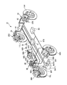
- FIG. 1 is a diagram showing an overall configuration of a brake system in a first embodiment.
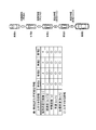
- FIG. 3 is a schematic diagram showing a premise configuration of platooning control of the first embodiment.
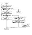
- 3 is a flowchart showing brake control in platooning according to the first embodiment.
- 3 is a flowchart showing brake control in platooning according to the first embodiment.
- FIG. 3 is a schematic diagram showing an inter-vehicle distance of each vehicle when the leading vehicle A generates a maximum deceleration, brakes, and stops during platooning control of the first embodiment.
- FIG. 3 is a schematic diagram showing an inter-vehicle distance of each vehicle when the leading vehicle A generates a maximum deceleration, brakes, and stops during platooning control of the first embodiment.
- FIG. 3 is a schematic diagram showing an inter-vehicle distance of each vehicle when a vehicle B traveling secondly generated a maximum deceleration, braked, and stopped during platooning control of the first embodiment.
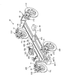
- FIG. 7 is a diagram showing an overall configuration of a brake system in a second embodiment. 8 is a flowchart showing brake control in platooning according to the second embodiment. 8 is a flowchart showing brake control in platooning according to the second embodiment.
- the brake system 1 can be applied to vehicles such as engine vehicles, hybrid vehicles, and electric vehicles.
- the vehicle has multiple (4) wheels.
- the front wheel 10 has a left front wheel 10L and a right front wheel 10R.
- the rear wheel 11 has a left rear wheel 11L and a right rear wheel 11R.
- the brake system 1 includes a brake device 20 (front wheel brake device) on the front wheel 10 side and a brake device 21 (rear wheel brake device) on the rear wheel 11 side.
- the vehicle has a main battery BAT1 and a sub battery BAT2.
- Electric power is supplied to the front wheel braking device 20 from the main battery BAT1 and forms a redundant system with the manual braking by the driver. Electric power is supplied to the rear wheel braking device 21 from both the main battery BAT1 and the sub-battery BAT2 to form a redundant system for supplying electric power.
- the front wheel braking device 20 of the first embodiment is an oil piezoelectric brake that drives a pump with a motor 302 to generate hydraulic pressure for braking.
- the front wheel braking device 20 has a brake pedal 201, an input rod 202, a reservoir tank 203, a master cylinder 204, a hydraulic brake mechanism 30, a stroke simulator 205, a front ECU 40, and a stroke sensor 500.
- the brake pedal 201 is a brake operation member to which a brake operation of a vehicle driver is input.
- the brake pedal 201 is connected to the master cylinder 204 via the input rod 202.
- the stroke sensor 500 detects the rotation angle of the brake pedal 201.
- This rotation angle corresponds to the stroke of the brake pedal 201 (pedal stroke).
- the detected pedal stroke may be the stroke of the input rod 202 connected to the master cylinder 204.
- the reservoir tank 203 stores the brake fluid (working fluid).
- the reservoir tank 203 is installed in the master cylinder 204 and can supply the master cylinder 204 with brake fluid.
- the master cylinder 204 internally generates brake fluid pressure (master cylinder pressure) in response to a brake operation.
- the master cylinder 204 is connected to a wheel cylinder (brake cylinder) 206 of the front wheel 10 via a brake pipe 207.
- the brake pipe 207 is provided for each system (left front wheel 10L and right front wheel 10R).
- the wheel cylinder 206 is a hydraulic caliper and propels the piston by the hydraulic pressure supplied through the brake pipe 207.
- the wheel cylinder 206 presses a brake pad as a braking member against the brake rotor by propelling the piston, and applies a friction braking force to the front wheels 10.
- the hydraulic brake mechanism 30 is a hydraulic control unit that can apply braking force to the front wheels 10 using hydraulic pressure.
- the hydraulic brake mechanism 30 is located in the middle of the brake pipe 207.
- the hydraulic brake mechanism 30 is connected to the reservoir tank 203 via the brake pipe 208.
- the housing of the hydraulic brake mechanism 30 has a plurality of liquid passages inside and houses a plurality of valves, a pump, and a plurality of hydraulic pressure sensors 50. Each valve can control opening and closing of the liquid passage.
- the pump is, for example, a plunger pump, and can supply the hydraulic pressure by discharging the brake fluid to the fluid passage.
- the pump is driven by the motor 302.
- the motor 302 is, for example, a brushed DC motor.
- the plurality of liquid passages form a hydraulic circuit.
- the hydraulic brake mechanism 30 can supply an arbitrary hydraulic pressure to the wheel cylinders 206 of the front wheels 10L, 10R by operating the pump and the valve, and can control the hydraulic pressures of the front wheels 10L, 10R independently of each other. .
- the motor 302 may be a three-phase DC brushless motor.
- the front ECU 40 is a first control device installed in the housing of the hydraulic brake mechanism 30 and capable of controlling the hydraulic brake mechanism 30.
- the front ECU 40 has a CPU, a drive circuit, and an interface circuit.
- the drive circuit has a solenoid drive circuit and a motor drive circuit.
- the interface circuit receives inputs of signals from the stroke sensor 500, the hydraulic pressure sensor, other sensors, and signals from other ECUs.
- These CPU, drive circuit, interface circuit, etc. function as a first control circuit capable of controlling the hydraulic brake mechanism 30, and by controlling the motor 302 and solenoid based on the input signal, the front wheels 10L, 10R Each hydraulic pressure supplied to the wheel cylinder 206 can be controlled.
- the stroke simulator 205 is installed in the housing of the hydraulic brake mechanism 30 and can communicate with the pressure chamber of the master cylinder 204.
- the stroke simulator 205 operates by accommodating the brake fluid flowing out from the pressure chamber of the master cylinder 204, and can generate a reaction force of the brake operation.
- the front ECU 40 causes the stroke simulator 205 to communicate with the pressure chamber of the master cylinder 204 in a state where the communication between the master cylinder 204 and the wheel cylinder 206 is cut off, thereby generating a reaction force according to a brake operation.
- the hydraulic brake mechanism 30 shuts off the communication between the master cylinder 204 and the stroke simulator 205 in the hydraulic circuit when hydraulic control cannot be executed, such as when the front ECU 40 fails or when the actuator (motor 302 or the like) fails, and the master brake The cylinder 204 side and the wheel cylinder 206 side are communicated. As a result, the master cylinder pressure can be supplied to each wheel cylinder 206, so that it is possible to apply a braking force to the front wheels 10 by a brake operation.
- the rear wheel braking device 21 has an electric braking device 210 and a rear ECU 41.
- the electric brake devices 210 are arranged on the left and right rear wheels 11L and 11R, respectively.
- the electric brake device 210 has an electric brake mechanism 31 and a sub ECU 42.
- the electric brake mechanism 31 is an electric caliper, and the electric motor drives the braking member. That is, the electric brake mechanism 31 can press the brake pad as the braking member against the brake rotor to apply the friction braking force to the rear wheel 11.
- the motor of the electric brake mechanism 31 is, for example, a three-phase DC brushless motor, and includes a resolver capable of detecting the rotation angle of the rotor of the motor. More specifically, as the electric brake mechanism 31, for example, those disclosed in JP-A-2006-105170 and JP-A-2006-183809 may be adopted.
- the electric brake mechanisms 31 of the rear wheels 11L and 11R can generate piston thrust by operating the motor independently of each other, and can hold the piston thrust by operating the latch mechanism.
- the case (housing) of the rear ECU 41 may be separate from the case of the front ECU 40, or may be common.
- the board of the rear ECU 41 may be separate from the board of the front ECU 40, or may be common.
- the sub ECU 42 is installed in the housing of each electric brake mechanism 31.
- the rear ECU 41 and the sub ECU 42 are communicably connected to each other via a dedicated communication line (signal line) 612.
- the rear ECU 41 and the sub ECU 42 are second control devices capable of controlling the electric brake mechanism 31.
- the rear ECU 41 has an upper CPU and an interface circuit.
- the interface circuit receives a signal from a parking brake switch or other sensor or a signal from another ECU.
- the sub ECU 42 has a lower CPU, a drive circuit, and an interface circuit.
- the interface circuit has an interface circuit to which the signal line of the sensor is connected, and receives an input of a signal from the CPU of the rear ECU 41.
- the sub-ECU 42 controls the motor and solenoid of the electric brake mechanism 31 based on signals from the rear ECU 41, sensors, etc. input via the interface circuit. Thereby, the piston thrust of the electric brake mechanism 31 and the operation of the latch mechanism can be controlled.
- the plurality of sensors include a wheel speed sensor, an acceleration sensor, a yaw rate sensor, and a steering angle sensor.
- the wheel speed sensor is arranged on each wheel 10L, 10R, 11L, 11R and detects the rotational angular speed (wheel speed) of each wheel 10L, 10R, 11L, 11R.
- the acceleration sensor detects vertical (front-rear) acceleration (front-rear G) and lateral (left-right) acceleration (lateral G) of the vehicle.
- the acceleration includes deceleration.
- the yaw rate sensor detects the yaw rate of the vehicle.
- the acceleration sensor and the yaw rate sensor are integrated as a composite sensor 55.
- the steering angle sensor detects the steering angle of the driver.
- the front ECU 40 and the rear ECU 41 are communicably connected to each other via a dedicated communication line (signal line) 611.
- the front ECU 40 can transmit the sensor signal acquired or received (hereinafter simply referred to as “acquired”) and the calculated command signal to the rear ECU 41 by communication.
- the rear ECU 41 can transmit the acquired sensor signal and the calculated command signal to the front ECU 40 by communication.
- the front ECU 40 and the rear ECU 41 transmit a signal regarding a traveling state to another ECU 43 (for example, an advanced driving support system ADAS that controls automatic brake control or the like) or another vehicle via an in-vehicle communication network (CAN) 610. It is connected so that it can communicate with the ECU of the platooning system that transmits and receives.
- the ECUs 40 and 41 can acquire a signal from the steering angle sensor (steering angle information) and an automatic brake command from the ECU 43.
- the front ECU 40 and the rear ECU 41 can control the hydraulic brake mechanism 30 and the electric brake mechanism 31, respectively, based on the acquired signals.
- the ECUs 40 and 41 can function as a vehicle control device by executing braking force control of the front wheels 10 and the rear wheels 11, respectively. That is, the front ECU 40 functions as an oil piezoelectric brake for controlling the braking force of the front wheels 10.
- the rear ECU 41 and the sub ECU 42 function as an electric brake for controlling the braking force of the rear wheels 11.
- the ECUs 40 to 42 can execute various brake controls.
- Brake control includes normal brake control, anti-lock brake control (ABS), traction control, brake control for vehicle motion control, regenerative cooperative brake control, automatic brake control, parking brake control, hill start assist control, platooning control. Including etc.
- Normal braking control generates a braking force that achieves a desired characteristic between the amount of brake operation and the vehicle deceleration required by the driver.
- ABS is a brake control for suppressing wheel lock due to braking.
- the traction control is brake control for suppressing drive slip of the wheels.
- Vehicle motion control includes vehicle behavior stabilization control such as skid prevention control (ESC).
- ESC skid prevention control
- the regenerative coordinated brake control generates a braking force whose sum with the regenerative braking force satisfies the vehicle deceleration required by the driver.
- the automatic brake control is a brake control necessary for realizing functions such as following the preceding vehicle (maintaining the following vehicle) and preventing collision.
- the hill start assist control is a brake control for keeping the vehicle stopped at the time of hill start and suppressing the vehicle from sliding down.
- FIG. 2 is a schematic diagram showing a premise configuration of platooning control of the first embodiment.
- the platooning is a control in which a plurality of vehicles such as vehicle A to vehicle E in FIG. 2 travel in a platoon while maintaining a predetermined inter-vehicle distance. For example, it is used when a shipping company or the like carries a large amount of parcels.
- Each vehicle is configured such that the traveling order, deceleration, inter-vehicle distance, vehicle speed, and target vehicle speed can be obtained as braking information of the vehicle ahead by vehicle-to-vehicle communication or the like.
- FIG. 3 and FIG. 4 are flowcharts showing the brake control in the row running of the first embodiment.
- step S1 the above-mentioned braking information of the preceding vehicle is obtained.
- step S2 it is determined based on the following conditional expression 1 whether or not the own vehicle and all the vehicles traveling in front need to be stopped or decelerated, and if the conditions are satisfied, the process proceeds to step S3, otherwise Proceed to Flow A (see FIG. 4). (Condition 1) Deceleration of a vehicle ahead ⁇ predetermined value and deceleration of own vehicle ⁇ predetermined value
- step S3 since the deceleration is equal to or lower than the predetermined deceleration, the inter-vehicle distance to the vehicle traveling in front of the host vehicle is set to the preset first inter-vehicle distance X1.
- step S4 it is determined whether the inter-vehicle distance between the host vehicle and the preceding vehicle is within a predetermined range with respect to the first inter-vehicle distance X1, and if it is within the predetermined range, the process proceeds to step S5, and if it is out of the predetermined range, step S6. Proceed to.
- step S5 it is determined that the vehicle is traveling in a row without requiring a brake operation, and the energization of the motor 302 of the front wheel braking device 20 which is an oil piezoelectric braking is stopped. Thereby, the current consumption is reduced.
- step S6 it is determined whether or not the inter-vehicle distance between the host vehicle and the preceding vehicle traveling immediately ahead is shorter than the first inter-vehicle distance X1, and if short, the process proceeds to step S7, and if long, the process proceeds to step S8.
- step S7 since the inter-vehicle distance is short, the braking force is limited to the braking force at which the deceleration is equal to or less than the predetermined value, and the braking is performed only by the electric braking device 210. In other words, the braking is performed only by the rear wheel braking device 21, and the inter-vehicle distance is controlled to be within the predetermined range with respect to the first inter-vehicle distance X1.
- step S8 the electric braking device 210 can control the braking force more finely and with better response than the hydraulic braking mechanism 30 of the front wheel braking device 20.
- step S8 there is no need to brake because the inter-vehicle distance is long. Therefore, the electric brake device 210 performs control to widen the clearance between the brake rotor and the brake pad to reduce friction.
- step S9 energization of the motor 302 of the front wheel braking device 20 is started. This is because it is necessary to operate the front wheel braking device 20 to stop / decelerate.
- the target inter-vehicle distance is set to the second inter-vehicle distance X2.
- the second inter-vehicle distance X2 is a distance that is set shorter than the first inter-vehicle distance X1 during platooning.
- the reason why the second inter-vehicle distance X2 is set to be shorter than the first inter-vehicle distance X1 is that a large inter-vehicle distance is not required when the vehicle is stopped and a margin allowance described later can be obtained.
- step S12 the allowance allowance X3 generated by shortening the inter-vehicle distance by setting the second inter-vehicle distance X2 is calculated by the following formula.
- X3 (number of vehicles from own vehicle to vehicle with maximum deceleration) ⁇ (X1-X2) Then, allowance allowance X3 is added to braking distance X ⁇ to calculate allowable braking distance Xcap.
- Xcap X ⁇ + X3
- step S13 the target braking force that can be stopped at the allowable braking distance Xcap is calculated by the following formula.
- the target vehicle speed of the host vehicle is VSP *
- the target deceleration is G *
- the vehicle speed at the start of deceleration is VSP_s
- the target braking force is F *
- the vehicle weight W1
- G * (VSP * 2- VSP_s2) / (2 ⁇ Xcap)
- F * W1 ⁇ G *
- the allowable braking distance Xcap is a value larger than the braking distance X ⁇ . In other words, the deceleration can be suppressed by increasing the braking distance.
- step S14 the braking force distribution of the front and rear wheels is calculated from the target braking force F *.
- the braking force distribution of the front and rear wheels may be set based on the well-known ideal braking force distribution characteristic and is not particularly limited.
- step S15 it is determined from the following equation whether the target braking force F * can be braked only by the rear wheel braking device 21 which is an electric brake.
- the maximum braking force of the electric brake mechanism 31 is defined as Frmax
- F * ⁇ Frmax it is determined that braking is possible only by the electric brake mechanism 31, and the process proceeds to step S16. Otherwise, the process proceeds to step S17. .
- step S16 braking is performed only by the rear wheel braking device 21 so as to achieve the target braking force F *, regardless of the braking force distribution of the front and rear wheels. As a result, it is not necessary to drive the motor 302 of the front wheel braking device 20, and the pump operating noise is suppressed to improve drivability.
- step S17 both the electric braking mechanism 31 of the rear wheel braking device 21 and the hydraulic braking mechanism 30 of the front wheel braking device 20 are used to perform braking based on the braking force distribution of the front and rear wheels calculated in step S14.
- FIG. 5 is a schematic diagram showing the inter-vehicle distance of each vehicle when the leading vehicle A generates the maximum deceleration, brakes, and stops during the platooning control of the first embodiment.
- FIG. 6 is a schematic diagram showing an inter-vehicle distance of each vehicle when the second vehicle B traveling during the platooning control of the first embodiment generates maximum deceleration, brakes, and then stops.
- the allowance X3 is calculated based on the vehicle that generates the maximum deceleration, and the allowable braking distance Xcap is calculated, so it is longer than when stopped at the first inter-vehicle distance X1.
- a braking distance can be secured. Therefore, the vehicle can be braked at a deceleration smaller than the deceleration of the vehicle that has generated the maximum deceleration, and the collapse of the load loaded on the vehicle and the accompanying damage to the load can be suppressed.
- the rear ECU 41 and the front ECU 40 are provided separately, but in the second embodiment, the rear ECU 410 has the electric brake mechanism 31 of the front wheel brake device 20 and the electric brake of the rear wheel brake device 21. The difference is that both of the mechanisms 31 are configured to be controllable.
- An ECU for controlling the front wheel braking device 20 may be separately provided and is not particularly limited.
- FIG. 8 and FIG. 9 are flowcharts showing brake control in platooning according to the second embodiment. Since the basic control flow is the same as that of the first embodiment, only different steps will be described. Step S5 of the first embodiment corresponds to step S50 of the second embodiment, step S7 of the first embodiment corresponds to step S70 of the second embodiment, step S8 of the first embodiment, Corresponding to step S80 of the second embodiment, step S15 of the first embodiment corresponds to step S150 of the second embodiment, step S16 of the first embodiment corresponds to step S160 of the second embodiment, The embodiment S17 corresponds to step S170 of the second embodiment. Note that step S9 in the first embodiment is omitted because it is a step for hydraulic piezoelectric braking.
- step S50 the inter-vehicle distance is within the predetermined range of the first inter-vehicle distance X1, so the electric brake device 210 of the front wheel braking device 20 controls the expansion of the clearance between the brake rotor and the brake pad to reduce friction. Since the electric brake device 210 of the rear wheel brake device 21 is used for controlling the inter-vehicle distance, no problem occurs in responsiveness.
- step S70 because the inter-vehicle distance is short, the deceleration is limited to a braking force that is less than or equal to a predetermined value, and braking is performed only by the electric braking device 210 of the rear wheel braking device 21. In other words, the braking is performed only by the rear wheel braking device 21, and the inter-vehicle distance is controlled to be within the predetermined range with respect to the first inter-vehicle distance X1.
- step S80 there is no need to brake because the distance between vehicles is long. Therefore, the electric brake device 210 of the rear wheel brake device 21 controls to widen the clearance between the brake rotor and the brake pad to reduce the friction.
- step S150 it is determined whether or not the target braking force F * can be braked only by the rear wheel braking device 21 that is an electric brake, and if it is determined that the rear wheel braking device 21 alone can brake, the process proceeds to step S160. Otherwise, to step S170.
- step S160 braking is performed only by the rear wheel braking device 21, regardless of the braking force distribution of the front and rear wheels.
- step S170 both the electric braking mechanism 31 of the rear wheel braking device 21 and the electric braking mechanism 31 of the front wheel braking device 20 are used to perform braking based on the braking force distribution of the front and rear wheels calculated in step S14.
- the front wheel braking device as an electric brake, the pad clearance of the front wheels can be expanded during platooning, and friction can be further reduced. Moreover, unlike the first embodiment, it is not necessary to control the energization state of the pump for activating the oil-piezoelectric brake, and power consumption can be reduced.
- a braking method for a vehicle having a braking system capable of independently controlling a braking force of a front wheel brake having an electric motor and a braking force of a rear wheel brake having an electric motor Receives deceleration information of a plurality of vehicles traveling in front of the own vehicle, and inter-vehicle distance information between the own vehicle and the plurality of vehicles, When the deceleration of the vehicle is less than a predetermined value, braking is performed using the rear wheel brake, When the deceleration of the vehicle is equal to or more than the predetermined value, the braking force required for the vehicle is calculated according to the allowable braking distance of the vehicle calculated from the deceleration information and the inter-vehicle distance information, The calculated braking force is supplied by using both the front wheel brake and the rear
- the vehicle braking method is, in one aspect thereof, A braking method for a vehicle by a braking system including an oil-piezoelectric brake and an electric brake, Braking to adjust the inter-vehicle distance using the electric brake, Stop braking is performed using both the oil-piezoelectric brake and the electric brake.
- a vehicle braking method of the present technical idea is, in one aspect thereof, A method of braking a vehicle by a brake system including an oil-piezoelectric brake and an electric brake, Receives deceleration information of a plurality of vehicles traveling in front of the own vehicle, and inter-vehicle distance information between the own vehicle and the plurality of vehicles, When the deceleration of the vehicle is less than a predetermined value, braking is performed using the electric brake, When the deceleration of the own vehicle is equal to or more than the predetermined value, it is necessary for the own vehicle according to the allowable braking distance of the own vehicle calculated from the deceleration information of the vehicle traveling in front of the own vehicle and the inter-vehicle distance information.
- the calculated braking force is supplied using both the oil-piezoelectric brake and the electric brake.
- braking is performed so that the inter-vehicle distance with the vehicle traveling in front of the own vehicle becomes the first inter-vehicle distance
- the second inter-vehicle distance smaller than the first inter-vehicle distance is set as an allowable minimum inter-vehicle distance
- the vehicle braking method is, in one aspect thereof, A braking method for a vehicle that travels while receiving deceleration information of a plurality of vehicles traveling in front of the vehicle, and inter-vehicle distance information between the vehicle and the plurality of vehicles, When the deceleration of the own vehicle is less than the predetermined value, braking is performed so that the inter-vehicle distance with the vehicle traveling in front of the own vehicle becomes the first inter-vehicle distance, When the deceleration of the host vehicle is equal to or more than the predetermined value, the second inter-vehicle distance smaller than the first inter-vehicle distance is set as an allowable minimum inter-vehicle distance, Among the plurality of vehicles traveling in front of the host vehicle, the number of vehicles between the host vehicle and the vehicle that needs
- the present invention is not limited to the above-described embodiment, and various modifications are included.
- the above-described embodiments have been described in detail in order to explain the present invention in an easy-to-understand manner, and are not necessarily limited to those including all the configurations described.
- a part of the configuration of one embodiment can be replaced with the configuration of another embodiment, and the configuration of one embodiment can be added to the configuration of another embodiment.
- brake device 10 front wheel 11 rear wheel 201 brake pedal 206 wheel cylinder 20 front wheel brake device 21 rear wheel brake device 30 hydraulic brake mechanism (oil piezoelectric brake) 31 electric brake mechanism (electric brake) 302 motor 40 front ECU 41 rear ECU 500 stroke sensor
Landscapes
- Engineering & Computer Science (AREA)
- Transportation (AREA)
- Mechanical Engineering (AREA)
- Regulating Braking Force (AREA)
Abstract
電動機を有する前輪ブレーキの制動力と、電動機を有する後輪ブレーキの制動力とを独立して制御できるブレーキシステムを備え、自車の前方を走行する複数の車両の減速度情報と車間距離情報とを受信し、自車の減速度が所定値未満の場合には、後輪ブレーキを用いて制動を行い、自車の減速度が所定値以上の場合には、減速度情報と車間距離情報から算出した自車の許容制動距離に応じて自車に必要な制動力を算出し、前輪ブレーキと後輪ブレーキとの両方を用いて制動することとした。
Description
本発明は、隊列走行時における車両の制動方法に関する。
特許文献1に開示されるように、隊列走行をする輸送車両において、隊列状態の保持を行う制動方法が開示されている。具体的には、車両の予測経路と隣接経路で移動する複数の対象物を同時に検知可能に構成された前方物体検知手段を備え、対象物の各々の速度及び距離を継続的に監視することで、先行車の挙動の悪影響を軽減している。
しかしながら、上記隊列走行時における制動方法では、対象物各々の速度と距離をパラメータとしており、減速度については考慮していなかった。言い換えると、減速度よりも対象物各々の速度や距離が優先されるため、制動時に減速度が大きくなる場合があり、車両に積載された荷物が動いてしまうことで、荷崩れや、それに伴い荷物へのダメージに繋がるおそれがあった。
本発明は、隊列走行時に減速度を抑制可能な車両の制動方法を提供することを目的とする。
本発明の1つの実施形態に係る車両の制動方法では、電動機を有する前輪ブレーキの制動力と、電動機を有する後輪ブレーキの制動力とを独立して制御できるブレーキシステムを備え、自車の前方を走行する複数の車両の減速度情報と車間距離情報とを受信し、自車の減速度が所定値未満の場合には、後輪ブレーキを用いて制動を行い、自車の減速度が所定値以上の場合には、減速度情報と車間距離情報から算出した自車の許容制動距離に応じて自車に必要な制動力を算出し、前輪ブレーキと後輪ブレーキとの両方を用いて制動することとした。
本発明の1つの実施形態に係る車両の制動方法によれば、許容制動距離に応じた制動力を発生させるため、車両の減速度を抑制することができ、車両に積載された荷物の荷崩れや、それに伴う荷物へのダメージを抑制できる。
以下、本発明を実施するための形態を、図面に基づき説明する。
[第1実施形態]
まず、本実施形態における車両のブレーキシステム1の全体の構成について、図1を用いて説明する。ブレーキシステム1は、エンジン自動車、ハイブリッド自動車や電気自動車等の車両に適用可能である。車両は複数(4つ)の車輪を備える。前輪10は、左前輪10Lおよび右前輪10Rを有する。後輪11は、左後輪11Lおよび右後輪11Rを有する。ブレーキシステム1は、前輪10の側のブレーキ装置20(前輪ブレーキ装置)および後輪11の側のブレーキ装置21(後輪ブレーキ装置)を有する。車両は、メインバッテリBAT1と、サブバッテリBAT2とを有する。前輪ブレーキ装置20には、メインバッテリBAT1から電力が供給され、運転者によるマニュアルブレーキとの間で冗長系を構成する。後輪ブレーキ装置21には、メインバッテリBAT1及びサブバッテリBAT2の両方から電力が供給され、電力供給の冗長系を構成する。
まず、本実施形態における車両のブレーキシステム1の全体の構成について、図1を用いて説明する。ブレーキシステム1は、エンジン自動車、ハイブリッド自動車や電気自動車等の車両に適用可能である。車両は複数(4つ)の車輪を備える。前輪10は、左前輪10Lおよび右前輪10Rを有する。後輪11は、左後輪11Lおよび右後輪11Rを有する。ブレーキシステム1は、前輪10の側のブレーキ装置20(前輪ブレーキ装置)および後輪11の側のブレーキ装置21(後輪ブレーキ装置)を有する。車両は、メインバッテリBAT1と、サブバッテリBAT2とを有する。前輪ブレーキ装置20には、メインバッテリBAT1から電力が供給され、運転者によるマニュアルブレーキとの間で冗長系を構成する。後輪ブレーキ装置21には、メインバッテリBAT1及びサブバッテリBAT2の両方から電力が供給され、電力供給の冗長系を構成する。
まず、前輪ブレーキ装置20について説明する。第1実施形態の前輪ブレーキ装置20は、モータ302でポンプを駆動し、油圧を発生させて制動する油圧電制ブレーキである。前輪ブレーキ装置20は、ブレーキペダル201、入力ロッド202、リザーバタンク203、マスタシリンダ204、油圧ブレーキ機構30、ストロークシミュレータ205、フロントECU40、およびストロークセンサ500を有する。ブレーキペダル201は、車両の運転者のブレーキ操作が入力されるブレーキ操作部材である。ブレーキペダル201は、入力ロッド202を介してマスタシリンダ204に接続される。ストロークセンサ500は、ブレーキペダル201の回転角度を検出する。この回転角度は、ブレーキペダル201のストローク(ペダルストローク)に相当する。なお、検出されるペダルストロークは、マスタシリンダ204に接続する入力ロッド202のストロークであってもよい。リザーバタンク203は、ブレーキ液(作動液)を貯留する。リザーバタンク203は、マスタシリンダ204に設置されており、マスタシリンダ204にブレーキ液を補給可能である。マスタシリンダ204は、ブレーキ操作に応じてブレーキ液の圧力(マスタシリンダ圧)を内部に発生する。マスタシリンダ204は、ブレーキ配管207を介して前輪10のホイルシリンダ(ブレーキシリンダ)206に接続される。ブレーキ配管207は系統(左前輪10Lおよび右前輪10R)毎にある。ホイルシリンダ206は、油圧式キャリパであり、ブレーキ配管207を介して供給される油圧により、ピストンを推進する。ホイルシリンダ206は、ピストンの推進により制動部材としてのブレーキパッドをブレーキロータに押し付け、前輪10に摩擦制動力を付与する。
油圧ブレーキ機構30は、油圧を用いて前輪10に対し制動力を付与可能な油圧制御ユニットである。油圧ブレーキ機構30は、ブレーキ配管207の途中にある。油圧ブレーキ機構30は、ブレーキ配管208を介してリザーバタンク203に接続される。油圧ブレーキ機構30のハウジングは、その内部に複数の液路を有し、複数の弁、ポンプ、および複数の油圧センサ50を収容する。各弁は、液路の開閉を制御可能である。ポンプは、例えばプランジャポンプであり、液路にブレーキ液を吐出して油圧を供給可能である。ポンプは、モータ302により駆動される。モータ302は、例えばブラシ付きDCモータである。複数の液路は油圧回路を形成する。油圧ブレーキ機構30は、ポンプおよび弁を作動させることで、前輪10L,10Rのホイルシリンダ206に任意の油圧を供給可能であると共に、前輪10L,10Rの上記油圧を互いに独立して制御可能である。例えば、ポンプと調整弁を作動させて元圧を発生させ、この状態で各ホイルシリンダ206に対応する増圧弁と減圧弁の開閉を制御することで、互いに異なる油圧を各ホイルシリンダ206に供給可能である。なお、モータ302は3相DCブラシレスモータとしてもよい。
フロントECU40は、油圧ブレーキ機構30のハウジングに設置され、油圧ブレーキ機構30を制御可能な第1の制御装置である。フロントECU40は、CPU、駆動回路、およびインターフェース回路を有する。駆動回路は、ソレノイド駆動回路とモータ駆動回路を有する。インターフェース回路は、ストロークセンサ500や油圧センサ、その他のセンサからの信号や、他のECUからの信号の入力を受ける。これらCPU、駆動回路、インターフェース回路等は、油圧ブレーキ機構30を制御可能な第1の制御回路として機能し、入力される信号に基づき、モータ302およびソレノイドを制御することで、前輪10L,10Rのホイルシリンダ206に供給する各油圧を制御可能である。
ストロークシミュレータ205は、油圧ブレーキ機構30のハウジングに設置され、マスタシリンダ204の圧力室に連通可能である。ストロークシミュレータ205は、マスタシリンダ204の圧力室から流出するブレーキ液を収容することで作動し、ブレーキ操作の反力を発生可能である。フロントECU40は、例えば、マスタシリンダ204とホイルシリンダ206との連通を遮断した状態で、ストロークシミュレータ205をマスタシリンダ204の圧力室に連通させることにより、ブレーキ操作に応じた反力を発生させる。
油圧ブレーキ機構30は、フロントECU40の故障時やアクチュエータ(モータ302等)の故障時など、油圧制御を実行できないとき、油圧回路におけるマスタシリンダ204とストロークシュミレータ205との連通を遮断し、かつ、マスタシリンダ204の側とホイルシリンダ206の側とを連通させる。これにより、マスタシリンダ圧が各ホイルシリンダ206に供給されうるため、ブレーキ操作により前輪10に制動力を付与することが可能である。
次に、後輪ブレーキ装置21について説明する。後輪ブレーキ装置21は、電動ブレーキ装置210、リヤECU41を有する。電動ブレーキ装置210は、左右後輪11L,11Rにそれぞれ配置される。電動ブレーキ装置210は、電動ブレーキ機構31およびサブECU42を有する。
電動ブレーキ機構31は、電動キャリパであり、電動機により制動部材を推進する。すなわち、電動ブレーキ機構31は、制動部材としてのブレーキパッドをブレーキロータに押し付け、後輪11に摩擦制動力を付与可能である。電動ブレーキ機構31のモータは、例えばとして3相DCブラシレスモータであり、モータのロータの回転角を検出可能なレゾルバを含む。より具体的には、電動ブレーキ機構31として、例えば特開2006-105170号公報や特開2006-183809号公報に開示されたものを採用してもよい。後輪11L,11Rの電動ブレーキ機構31は、互いに独立して、モータを作動させることでピストン推力を発生可能であると共に、ラッチ機構を作動させることでピストン推力を保持可能である。
リヤECU41のケース(ハウジング)は、フロントECU40のケースと別体であってもよいし、共通であってもよい。ケースが共通である場合、リヤECU41の基板は、フロントECU40の基板と別体であってもよいし、共通であってもよい。サブECU42は、各電動ブレーキ機構31のハウジングに設置される。リヤECU41とサブECU42は、専用の通信線(信号線)612を介して、互いに通信可能に接続される。リヤECU41およびサブECU42は、電動ブレーキ機構31を制御可能な第2の制御装置である。リヤECU41は、上位のCPUおよびインターフェース回路を有する。インターフェース回路は、パーキングブレーキスイッチその他のセンサからの信号や、他のECUからの信号の入力を受ける。サブECU42は、下位のCPU、駆動回路、およびインターフェース回路を有する。インターフェース回路は、センサの信号線が接続されるインターフェース回路を有するほか、リヤECU41のCPUからの信号の入力を受ける。サブECU42は、インターフェース回路を介して入力されるリヤECU41やセンサ等からの信号に基づき、電動ブレーキ機構31のモータおよびソレノイドを制御する。これにより、当該電動ブレーキ機構31のピストン推力およびラッチ機構の作動を制御可能である。
フロントECU40およびリヤECU41には、車両における複数のセンサが接続されている。これら複数のセンサは、車輪速センサ、加速度センサ、ヨーレートセンサ、および舵角センサを有する。車輪速センサは、各車輪10L,10R,11L,11Rに配置され、各車輪10L,10R,11L,11Rの回転角速度(車輪速)を検出する。加速度センサは、車両の縦(前後)方向の加速度(前後G)および横(左右)方向の加速度(横G)を検出する。ここで加速度は減速度も含む。ヨーレートセンサは、車両のヨーレートを検出する。加速度センサ及びヨーレートセンサは、複合センサ55として一体化されている。舵角センサは、運転者の操舵角を検出する。
フロントECU40とリヤECU41は、専用の通信線(信号線)611を介して、互いに通信可能に接続される。フロントECU40は、取得または受信(以下、単に取得という。)したセンサ信号や算出した指令信号を、通信によって、リヤECU41に伝達することが可能である。また、リヤECU41は、取得したセンサ信号や算出した指令信号を、通信によって、フロントECU40に伝達することが可能である。また、フロントECU40およびリヤECU41は、車載の通信網(CAN)610を介して、別のECU43(例えば自動ブレーキ制御等を司る先進運転支援システムADASや、他車両との間で走行状態に関する信号を送受信する隊列走行システムのECU)と通信可能に接続される。ECU40,41は、ECU43から、舵角センサの信号(操舵角情報)や自動ブレーキ指令を取得可能である。
フロントECU40およびリヤECU41は、上記取得した信号に基づき、それぞれ油圧ブレーキ機構30および電動ブレーキ機構31を制御可能である。ECU40,41は、それぞれ前輪10と後輪11の制動力制御を実行することで、車両の制御装置として機能しうる。すなわち、フロントECU40は、前輪10の制動力を制御するための油圧電制ブレーキとして機能する。リヤECU41およびサブECU42は、後輪11の制動力を制御するための電動ブレーキとして機能する。これにより、ECU40~42は、各種のブレーキ制御を実行可能である。ブレーキ制御は、通常ブレーキ制御、アンチロックブレーキ制御(ABS)、トラクション制御、車両の運動制御のためのブレーキ制御、回生協調ブレーキ制御、自動ブレーキ制御、パーキングブレーキ制御、坂道発進補助制御、隊列走行制御等を含む。
通常ブレーキ制御は、ブレーキ操作量と運転者の要求する車両減速度との間の所望の特性を実現するような制動力を発生させる。ABSは、制動による車輪のロックを抑制するためのブレーキ制御である。トラクション制御は、車輪の駆動スリップを抑制するためのブレーキ制御である。車両の運動制御は、横滑り防止制御(ESC)等の車両挙動安定化制御を含む。回生協調ブレーキ制御は、回生制動力との和が、運転者の要求する車両減速度を充足するような制動力を発生させる。自動ブレーキ制御は、先行車追従(車間維持)や衝突防止等の機能実現に必要なブレーキ制御である。坂道発進補助制御は、坂道発進時等で停車を維持して車両のずり下がりを抑制するためのブレーキ制御である。
(隊列走行制御について)
図2は、第1実施形態の隊列走行制御の前提構成を表す概略図である。隊列走行とは、例えば、図2の車両Aから車両Eといった複数の車両が、所定の車間距離を保ちながら隊列を組んで走行する制御である。例えば、運送会社等が荷物を大量に搬送する際に採用される。各車両は、車車間通信等により前方の車両の制動情報として、走行順番、減速度、車間距離、車速、目標車速を入手可能に構成されている。車両Eの場合、前方に位置する各車両A,B,C,Dにおける隊列の走行順番、減速度、車間距離、車速、目標車速を入手可能である。そして、隊列の車両のいずれかが制動すると、各車両の車間距離や減速度に応じて制動制御を実施する。
図2は、第1実施形態の隊列走行制御の前提構成を表す概略図である。隊列走行とは、例えば、図2の車両Aから車両Eといった複数の車両が、所定の車間距離を保ちながら隊列を組んで走行する制御である。例えば、運送会社等が荷物を大量に搬送する際に採用される。各車両は、車車間通信等により前方の車両の制動情報として、走行順番、減速度、車間距離、車速、目標車速を入手可能に構成されている。車両Eの場合、前方に位置する各車両A,B,C,Dにおける隊列の走行順番、減速度、車間距離、車速、目標車速を入手可能である。そして、隊列の車両のいずれかが制動すると、各車両の車間距離や減速度に応じて制動制御を実施する。
図3及び図4は、第1実施形態の隊列走行におけるブレーキ制御を表すフローチャートである。
ステップS1では、上述した前方車両の制動情報を入手する。
ステップS2では、自車及び前方を走行している全ての車両が停止または減速が必要か否かを下記条件式1に基づいて判断し、条件を満たした場合はステップS3に進み、それ以外はフローA(図4参照)に進む。(条件式1)前方車両の減速度≦所定値、かつ、自車の減速度≦所定値
ステップS1では、上述した前方車両の制動情報を入手する。
ステップS2では、自車及び前方を走行している全ての車両が停止または減速が必要か否かを下記条件式1に基づいて判断し、条件を満たした場合はステップS3に進み、それ以外はフローA(図4参照)に進む。(条件式1)前方車両の減速度≦所定値、かつ、自車の減速度≦所定値
ステップS3では、減速度が所定減速度以下であるため、自車の前方を走行する車両との車間距離を予め設定された第1車間距離X1に設定する。
ステップS4では、自車と前方車両の車間距離が第1車間距離X1に対して所定範囲内か否かを判断し、所定範囲内の場合はステップS5に進み、所定範囲外の場合はステップS6に進む。
ステップS5では、ブレーキ操作を必要とせず隊列走行していると判断し、油圧電制ブレーキである前輪ブレーキ装置20のモータ302への通電を停止する。これにより、消費電流の低減を図る。
ステップS4では、自車と前方車両の車間距離が第1車間距離X1に対して所定範囲内か否かを判断し、所定範囲内の場合はステップS5に進み、所定範囲外の場合はステップS6に進む。
ステップS5では、ブレーキ操作を必要とせず隊列走行していると判断し、油圧電制ブレーキである前輪ブレーキ装置20のモータ302への通電を停止する。これにより、消費電流の低減を図る。
ステップS6では、自車とすぐ前方を走行する前方車両との車間距離が第1車間距離X1より短いか否かを判断し、短い場合はステップS7に進み、長い場合はステップS8に進む。
ステップS7では、車間距離が短いため、減速度が所定値以下となる制動力に制限して電動ブレーキ装置210のみによる制動を行う。言い換えると、後輪ブレーキ装置21のみで制動し、車間距離が第1車間距離X1に対して所定範囲内となるように制御する。電動ブレーキ装置210は、前輪ブレーキ装置20の油圧ブレーキ機構30に比べて、きめ細やかに、かつ、応答性良く制動力を制御できるからである。
ステップS8では、車間距離が長いため、制動する必要が無い。よって、電動ブレーキ装置210によってブレーキロータとブレーキパッドとのクリアランスを広げる制御を行い、フリクションを低減する。
ステップS7では、車間距離が短いため、減速度が所定値以下となる制動力に制限して電動ブレーキ装置210のみによる制動を行う。言い換えると、後輪ブレーキ装置21のみで制動し、車間距離が第1車間距離X1に対して所定範囲内となるように制御する。電動ブレーキ装置210は、前輪ブレーキ装置20の油圧ブレーキ機構30に比べて、きめ細やかに、かつ、応答性良く制動力を制御できるからである。
ステップS8では、車間距離が長いため、制動する必要が無い。よって、電動ブレーキ装置210によってブレーキロータとブレーキパッドとのクリアランスを広げる制御を行い、フリクションを低減する。
ステップS9では、前輪ブレーキ装置20のモータ302への通電を開始する。停止・減速するために前輪ブレーキ装置20の作動が必要だからである。
ステップS10では、前方車両のうち、最大の減速度で制動を行う車両(以下、最大減速車両と記載する。)の停止時における制動距離Xα(α=A,B,C,D)を下記式に基づいて推定する。ここで、最大減速車両の目標車速をVSPmax*、減速度をGmax、減速開始時の車速をVSPmax_sと定義すると、Xα=(VSPmax*2-VSPmax_s2)/(2×Gmax)
ステップS11では、目標車間距離を第2車間距離X2に設定する。第2車間距離X2とは、隊列走行中の第1車間距離X1に比べて短く設定された距離である。第2車間距離X2を第1車間距離X1よりも短く設定したのは、車両停車時に大きな車間距離は不要であること、また、後述する余裕代を得られることによる。
ステップS12では、車間距離を第2車間距離X2とすることで短くなることによって生じる余裕代X3を下記式により算出する。X3=(自車から最大の減速度の車両までの台数)×(X1-X2)次に、制動距離Xαに余裕代X3を加算し、許容制動距離Xcapを算出する。Xcap=Xα+X3
ステップS13では、許容制動距離Xcapで停止可能な目標制動力を下記式により算出する。ここで、自車の目標車速をVSP*、目標減速度をG*、減速開始時の車速をVSP_s、目標制動力をF*、車両重量をW1と定義すると、G*=(VSP*2-VSP_s2)/(2×Xcap)F*=W1×G*尚、許容制動距離Xcapは、制動距離Xαよりも大きな値である。言い換えると、制動距離を長くすることで減速度を抑制できる。
ステップS14では、目標制動力F*から前後輪の制動力配分を算出する。尚、前後輪の制動力配分については、周知の理想制動力配分特性に基づいて設定すればよく、特に限定しない。
ステップS15では、目標制動力F*が電動ブレーキである後輪ブレーキ装置21のみで制動できるか否かを下記式より判断する。ここで、電動ブレーキ機構31の最大制動力をFrmaxと定義すると、F*≦Frmaxの場合、電動ブレーキ機構31のみで制動可能と判断してステップS16に進み、それ以外の場合はステップS17に進む。
ステップS15では、目標制動力F*が電動ブレーキである後輪ブレーキ装置21のみで制動できるか否かを下記式より判断する。ここで、電動ブレーキ機構31の最大制動力をFrmaxと定義すると、F*≦Frmaxの場合、電動ブレーキ機構31のみで制動可能と判断してステップS16に進み、それ以外の場合はステップS17に進む。
ステップS16では、前後輪の制動力配分に関わらず、目標制動力F*を達成するように後輪ブレーキ装置21のみで制動を行う。これにより、前輪ブレーキ装置20のモータ302を駆動する必要が無く、ポンプ作動音を抑制することで、運転性を向上する。
ステップS17では、後輪ブレーキ装置21の電動ブレーキ機構31と前輪ブレーキ装置20の油圧ブレーキ機構30の両方を用い、ステップS14で算出された前後輪の制動力配分に基づいて制動する。
ステップS17では、後輪ブレーキ装置21の電動ブレーキ機構31と前輪ブレーキ装置20の油圧ブレーキ機構30の両方を用い、ステップS14で算出された前後輪の制動力配分に基づいて制動する。
図5は、第1実施形態の隊列走行制御中に先頭車両Aが最大減速度を発生して制動し、停止した場合の各車両の車間距離を表す概略図である。自車は車両Dである。α=Aであるため、最大減速車両の制動距離XAを算出する。次に、自車Dから最大の減速度の車両Aまでの台数は車両Aを含めて3台である。よって、車両停止時に必要な第2車間距離X2と第1車間距離X1との差に、3を掛けて余裕代X3を算出し、許容制動距離Xcap(=XA+X3)を算出する。
図6は、第1実施形態の隊列走行制御中に二番目を走行している車両Bが最大減速度を発生して制動し、停止した場合の各車両の車間距離を表す概略図である。自車は車両Dである。α=Bであるため、最大減速車両の制動距離XBを算出する。次に、自車Dから最大の減速度の車両Bまでの台数は車両Bを含めて2台である。よって、車両停止時に必要な第2車間距離と第1車間距離X1との差に、2を掛けて余裕代X3を算出し、許容制動距離Xcap(=XB+X3)を算出する。
このように、隊列走行制御中に、最大減速度を発生する車両を基準として余裕代X3を算出し、許容制動距離Xcapを算出するため、第1車間距離X1で停止した場合に比べて、長い制動距離を確保することができる。よって、最大減速度を発生した車両の減速度よりも小さな減速度で車両を制動することができ、車両に積載された荷物の荷崩れや、それに伴う荷物へのダメージを抑制できる。
[第2実施形態]
本実施形態における車両のブレーキシステム1の全体の構成について、図7を用いて説明する。第1実施形態では、前輪ブレーキ装置20として、油圧電制ブレーキを採用したが、第2実施形態では、前輪ブレーキ装置20として後輪ブレーキ装置21と同様、電動ブレーキ機構31を採用した点が異なる。尚、マスタシリンダ204とストロークシミュレータ205とを組み合わせて、マスタシリンダ204の圧力室から流出するブレーキ液を収容することで作動し、ブレーキ操作の反力を発生可能な点は同じである。また、第1実施形態では、リヤECU41とフロントECU40とを個別に設けたが、第2実施形態では、リヤECU410が、前輪ブレーキ装置20の電動ブレーキ機構31と、後輪ブレーキ装置21の電動ブレーキ機構31の両方を制御可能に構成されている点で異なる。尚、前輪ブレーキ装置20を制御するECUを別途設けてもよく、特に限定しない。
本実施形態における車両のブレーキシステム1の全体の構成について、図7を用いて説明する。第1実施形態では、前輪ブレーキ装置20として、油圧電制ブレーキを採用したが、第2実施形態では、前輪ブレーキ装置20として後輪ブレーキ装置21と同様、電動ブレーキ機構31を採用した点が異なる。尚、マスタシリンダ204とストロークシミュレータ205とを組み合わせて、マスタシリンダ204の圧力室から流出するブレーキ液を収容することで作動し、ブレーキ操作の反力を発生可能な点は同じである。また、第1実施形態では、リヤECU41とフロントECU40とを個別に設けたが、第2実施形態では、リヤECU410が、前輪ブレーキ装置20の電動ブレーキ機構31と、後輪ブレーキ装置21の電動ブレーキ機構31の両方を制御可能に構成されている点で異なる。尚、前輪ブレーキ装置20を制御するECUを別途設けてもよく、特に限定しない。
(隊列走行制御について)
図8及び図9は、第2実施形態の隊列走行におけるブレーキ制御を表すフローチャートである。基本的な制御フローは、第1実施形態と同じであるため、異なるステップについてのみ説明する。第1実施形態のステップS5は、第2実施形態のステップS50と対応し、第1実施形態のステップS7は、第2実施形態のステップS70と対応し、第1実施形態のステップS8は、第2実施形態のステップS80と対応し、第1実施形態のステップS15は、第2実施形態のステップS150に対応し、第1実施形態のステップS16は、第2実施形態のステップS160に対応し、実施形態S17は、第2実施形態のステップS170に対応する。尚、第1実施形態のステップS9は、油圧電制ブレーキ用のステップであるため、削除されている。
図8及び図9は、第2実施形態の隊列走行におけるブレーキ制御を表すフローチャートである。基本的な制御フローは、第1実施形態と同じであるため、異なるステップについてのみ説明する。第1実施形態のステップS5は、第2実施形態のステップS50と対応し、第1実施形態のステップS7は、第2実施形態のステップS70と対応し、第1実施形態のステップS8は、第2実施形態のステップS80と対応し、第1実施形態のステップS15は、第2実施形態のステップS150に対応し、第1実施形態のステップS16は、第2実施形態のステップS160に対応し、実施形態S17は、第2実施形態のステップS170に対応する。尚、第1実施形態のステップS9は、油圧電制ブレーキ用のステップであるため、削除されている。
ステップS50では、車間距離が第1車間距離X1の所定範囲内であるため、前輪ブレーキ装置20の電動ブレーキ装置210によってブレーキロータとブレーキパッドとのクリアランスを広げる制御を行い、フリクションを低減する。尚、車間距離制御用には、後輪ブレーキ装置21の電動ブレーキ装置210を使用するため、応答性に問題は生じない。
ステップS70では、車間距離が短いため、減速度が所定値以下となる制動力に制限して後輪ブレーキ装置21の電動ブレーキ装置210のみによる制動を行う。言い換えると、後輪ブレーキ装置21のみで制動し、車間距離が第1車間距離X1に対して所定範囲内となるように制御する。
ステップS80では、車間距離が長いため、制動する必要が無い。よって、後輪ブレーキ装置21の電動ブレーキ装置210によってブレーキロータとブレーキパッドとのクリアランスを広げる制御を行い、フリクションを低減する。
ステップS150では、目標制動力F*が電動ブレーキである後輪ブレーキ装置21のみで制動できるか否かを下記式より判断し、後輪ブレーキ装置21のみで制動可能と判断した場合はステップS160に進み、それ以外の場合はステップS170に進む。
ステップS160では、前後輪の制動力配分に関わらず、後輪ブレーキ装置21のみで制動を行う。
ステップS170では、後輪ブレーキ装置21の電動ブレーキ機構31と前輪ブレーキ装置20の電動ブレーキ機構31の両方を用い、ステップS14で算出された前後輪の制動力配分に基づいて制動する。
ステップS170では、後輪ブレーキ装置21の電動ブレーキ機構31と前輪ブレーキ装置20の電動ブレーキ機構31の両方を用い、ステップS14で算出された前後輪の制動力配分に基づいて制動する。
このように、前輪のブレーキ装置を電動ブレーキとすることで、隊列走行中における前輪のパッドクリアランスを広げることができ、よりフリクションを低減できる。また、第1実施形態のように、油圧電制ブレーキのポンプ作動用モータに対する通電状態を制御する必要が無く、消費電力を低減できる。
[実施形態から把握しうる技術的思想]
以上説明した実施形態から把握しうる技術的思想(又は技術的解決策。以下同じ。)について、以下に記載する。
(1) 本技術的思想の車両の制動方法は、その1つの態様において、
電動機を有する前輪ブレーキの制動力と、電動機を有する後輪ブレーキの制動力とを独立して制御できるブレーキシステムを備えた車両の制動方法であって、
自車の前方を走行する複数の車両の減速度情報と、前記自車と前記複数の車両との間の車間距離情報とを受信し、
自車の減速度が所定値未満の場合には、前記後輪ブレーキを用いて制動を行い、
自車の減速度が前記所定値以上の場合には、前記減速度情報と前記車間距離情報から算出した自車の許容制動距離に応じて自車に必要な制動力を算出し、
前記前輪ブレーキと前記後輪ブレーキとの両方を用いて、前記算出された制動力を供給する。
(2) また、他の観点から、本技術的思想の車両の制動方法は、その1つの態様において、
油圧電制ブレーキと電動ブレーキとを備えたブレーキシステムにより車両の制動方法であって、
前記電動ブレーキを用いて車間距離を調整する制動を行い、
前記油圧電制ブレーキと前記電動ブレーキとの両方を用いて停車制動を行う。
(3) また、他の観点から、本技術的思想の車両の制動方法は、その1つの態様において、
油圧電制ブレーキと電動ブレーキとを備えたブレーキシステムによる車両の制動方法であって、
自車の前方を走行する複数の車両の減速度情報と、前記自車と前記複数の車両との間の車間距離情報とを受信し、
自車の減速度が所定値未満の場合には、前記電動ブレーキを用いて制動を行い、
自車の減速度が前記所定値以上の場合には、自車の前方を走行する車両の前記減速度情報と前記車間距離情報から算出した自車の許容制動距離に応じて自車に必要な制動力を算出し、
前記油圧電制ブレーキと前記電動ブレーキとの両方を用いて、前記算出された制動力を供給する。
(4) より好ましい態様では、前記態様において、
自車の減速度が前記所定値未満の場合には、自車の前方を走行する車両との車間距離が第1の車間距離となるように制動し、
自車の減速度が前記所定値以上の場合には、前記第1の車間距離よりも小さい第2の車間距離を許容最小車間距離とし、
自車の前方を走行する複数車両のうち最大の減速度で制動する必要のある車両と自車との間の車両の車両数と、前記第1の車間距離と、前記許容最小車間距離とから、自車に必要な制動距離を算出する。
(5) 別の好ましい態様では、前記態様のいずれかにおいて、
前記油圧電制ブレーキを駆動するモータは、減速度が前記所定値未満の場合に停止する。
(6) また、他の観点から、本技術的思想の車両の制動方法は、その1つの態様において、
自車の前方を走行する複数の車両の減速度情報と、前記自車と前記複数の車両との間の車間距離情報とを受信しながら走行する車両の制動方法であって、
自車の減速度が所定値未満の場合には、自車の前方を走行する車両との車間距離が第1の車間距離となるように制動し、
自車の減速度が前記所定値以上の場合には、前記第1の車間距離よりも小さい第2の車間距離を許容最小車間距離とし、
自車の前方を走行する複数車両のうち最大の減速度で制動する必要のある車両と自車との間の車両数と、前記第1の車間距離と、前記許容最小車間距離と、から自車に必要な制動距離を算出する。
尚、本発明は上記した実施形態に限定されるものではなく、様々な変形例が含まれる。例えば、上記した実施形態は本発明を分かりやすく説明するために詳細に説明したものであり、必ずしも説明した全ての構成を備えるものに限定されるものではない。また、ある実施形態の構成の一部を他の実施形態の構成に置き換えることが可能であり、また、ある実施形態の構成に他の実施形態の構成を加えることも可能である。また、各実施形態の構成の一部について、他の構成の追加・削除・置換をすることが可能である。
本願は、2018年10月24日付出願の日本国特許出願第2018-200255号に基づく優先権を主張する。2018年10月24日付出願の日本国特許出願第2018-200255号の明細書、特許請求の範囲、図面、及び要約書を含む全開示内容は、参照により本願に全体として組み込まれる。
1 ブレーキ装置10 前輪11 後輪201 ブレーキペダル206 ホイルシリンダ20 前輪ブレーキ装置21 後輪ブレーキ装置30 油圧ブレーキ機構(油圧電制ブレーキ)31 電動ブレーキ機構(電動ブレーキ)302 モータ40 フロントECU41 リヤECU500 ストロークセンサ
Claims (6)
- 車両の制動方法であって、
前記車両は、電動機を有する前輪ブレーキの制動力と、電動機を有する後輪ブレーキの制動力とを独立して制御できるブレーキシステムを備えており、
前記車両の制動方法は、
自車の前方を走行する複数の車両の減速度情報と、前記自車と前記複数の車両との間の車間距離情報とを受信し、
自車の減速度が所定値未満の場合には、前記後輪ブレーキを用いて制動を行い、
自車の減速度が前記所定値以上の場合には、前記減速度情報と前記車間距離情報から算出した自車の許容制動距離に応じて自車に必要な制動力を算出し、
前記前輪ブレーキと前記後輪ブレーキとの両方を用いて、前記算出された制動力を供給することを特徴とする車両の制動方法。 - 油圧電制ブレーキと電動ブレーキとを備えたブレーキシステムにより車両の制動方法であって、
前記電動ブレーキを用いて車間距離を調整する制動を行い、
前記油圧電制ブレーキと前記電動ブレーキとの両方を用いて停車制動を行うことを特徴とする車両の制動方法。 - 油圧電制ブレーキと電動ブレーキとを備えたブレーキシステムによる車両の制動方法であって、
自車の前方を走行する複数の車両の減速度情報と、前記自車と前記複数の車両との間の車間距離情報とを受信し、
自車の減速度が所定値未満の場合には、前記電動ブレーキを用いて制動を行い、
自車の減速度が前記所定値以上の場合には、自車の前方を走行する車両の前記減速度情報と前記車間距離情報から算出した自車の許容制動距離とに応じて自車に必要な制動力を算出し、
前記油圧電制ブレーキと前記電動ブレーキとの両方を用いて、前記算出された制動力を供給することを特徴とする車両の制動方法。 - 請求項3に記載の車両の制動方法において、
自車の減速度が前記所定値未満の場合には、自車の前方を走行する車両との車間距離が第1の車間距離となるように制動し、
自車の減速度が前記所定値以上の場合には、前記第1の車間距離よりも小さい第2の車間距離を許容最小車間距離とし、
自車の前方を走行する複数車両のうち最大の減速度で制動する必要のある車両と自車との間の車両の車両数と、前記第1の車間距離と、前記許容最小車間距離とから、自車に必要な制動距離を算出することを特徴とする車両の制動方法。 - 請求項1ないし4いずれか一項に記載の車両の制動方法において、
前記油圧電制ブレーキを駆動するモータは、減速度が前記所定値未満の場合に停止することを特徴とする車両の制動方法。 - 自車の前方を走行する複数の車両の減速度情報と、前記自車と前記複数の車両との間の車間距離情報とを受信しながら走行する車両の制動方法であって、
自車の減速度が所定値未満の場合には、自車の前方を走行する車両との車間距離が第1の車間距離となるように制動し、
自車の減速度が前記所定値以上の場合には、前記第1の車間距離よりも小さい第2の車間距離を許容最小車間距離とし、
自車の前方を走行する複数車両のうち最大の減速度で制動する必要のある車両と自車との間の車両数と、前記第1の車間距離と、前記許容最小車間距離とから自車に必要な制動距離を算出することを特徴とする車両の制動方法。
Priority Applications (1)
| Application Number | Priority Date | Filing Date | Title |
|---|---|---|---|
| JP2020552936A JPWO2020084915A1 (ja) | 2018-10-24 | 2019-09-04 | 車両の制動方法 |
Applications Claiming Priority (2)
| Application Number | Priority Date | Filing Date | Title |
|---|---|---|---|
| JP2018200255 | 2018-10-24 | ||
| JP2018-200255 | 2018-10-24 |
Publications (1)
| Publication Number | Publication Date |
|---|---|
| WO2020084915A1 true WO2020084915A1 (ja) | 2020-04-30 |
Family
ID=70332200
Family Applications (1)
| Application Number | Title | Priority Date | Filing Date |
|---|---|---|---|
| PCT/JP2019/034732 Ceased WO2020084915A1 (ja) | 2018-10-24 | 2019-09-04 | 車両の制動方法 |
Country Status (2)
| Country | Link |
|---|---|
| JP (1) | JPWO2020084915A1 (ja) |
| WO (1) | WO2020084915A1 (ja) |
Cited By (1)
| Publication number | Priority date | Publication date | Assignee | Title |
|---|---|---|---|---|
| US20250206307A1 (en) * | 2022-03-31 | 2025-06-26 | Robert Bosch Gmbh | Controller and control method for behavior of straddle-type vehicle |
Citations (3)
| Publication number | Priority date | Publication date | Assignee | Title |
|---|---|---|---|---|
| JP2015022422A (ja) * | 2013-07-17 | 2015-02-02 | 日産自動車株式会社 | 隊列走行制御装置、隊列走行制御方法 |
| WO2018043520A1 (ja) * | 2016-08-30 | 2018-03-08 | ナブテスコオートモーティブ株式会社 | 車両および隊列走行車両群 |
| JP2018122741A (ja) * | 2017-02-01 | 2018-08-09 | トヨタ自動車株式会社 | 車両用ブレーキシステム |
-
2019
- 2019-09-04 WO PCT/JP2019/034732 patent/WO2020084915A1/ja not_active Ceased
- 2019-09-04 JP JP2020552936A patent/JPWO2020084915A1/ja active Pending
Patent Citations (3)
| Publication number | Priority date | Publication date | Assignee | Title |
|---|---|---|---|---|
| JP2015022422A (ja) * | 2013-07-17 | 2015-02-02 | 日産自動車株式会社 | 隊列走行制御装置、隊列走行制御方法 |
| WO2018043520A1 (ja) * | 2016-08-30 | 2018-03-08 | ナブテスコオートモーティブ株式会社 | 車両および隊列走行車両群 |
| JP2018122741A (ja) * | 2017-02-01 | 2018-08-09 | トヨタ自動車株式会社 | 車両用ブレーキシステム |
Cited By (1)
| Publication number | Priority date | Publication date | Assignee | Title |
|---|---|---|---|---|
| US20250206307A1 (en) * | 2022-03-31 | 2025-06-26 | Robert Bosch Gmbh | Controller and control method for behavior of straddle-type vehicle |
Also Published As
| Publication number | Publication date |
|---|---|
| JPWO2020084915A1 (ja) | 2021-09-02 |
Similar Documents
| Publication | Publication Date | Title |
|---|---|---|
| JP7145269B2 (ja) | ブレーキ装置、車両の制御装置及び電動ブレーキ制御装置 | |
| JP6588981B2 (ja) | 加減速制御装置 | |
| JP6219186B2 (ja) | ブレーキ制御装置 | |
| CN111094087B (zh) | 制动装置、车辆控制装置 | |
| CN111278692B (zh) | 车辆的制动控制装置 | |
| CN111683845B (zh) | 车辆的制动控制装置 | |
| US8439149B2 (en) | Brake equipment of vehicle with driver seat whose direction is changeable | |
| CN115427270A (zh) | 行驶动力系统和中央控制电动汽车 | |
| CN111683843B (zh) | 车辆的制动控制装置 | |
| US11597367B2 (en) | Hydraulic brake system | |
| US20170297547A1 (en) | Brake control device | |
| JPWO2020241637A1 (ja) | ブレーキシステム、制動力配分装置および電動ブレーキ装置 | |
| JP5988560B2 (ja) | 車体挙動安定化装置 | |
| JP6935712B2 (ja) | 車両の制動制御装置 | |
| CN103129538A (zh) | 制动控制装置 | |
| KR20130035204A (ko) | 브레이크 제어 장치 | |
| JP2600876B2 (ja) | 車両の旋回制御装置 | |
| JP5856133B2 (ja) | 車両用制動システム | |
| JP5566873B2 (ja) | 車両用ブレーキ装置 | |
| JPWO2020084915A1 (ja) | 車両の制動方法 | |
| JP2018088735A (ja) | ブレーキ制御装置 | |
| JP2022118893A (ja) | 車両の制動制御装置 | |
| JP2007038884A (ja) | 車両の制動制御装置 |
Legal Events
| Date | Code | Title | Description |
|---|---|---|---|
| 121 | Ep: the epo has been informed by wipo that ep was designated in this application |
Ref document number: 19874804 Country of ref document: EP Kind code of ref document: A1 |
|
| ENP | Entry into the national phase |
Ref document number: 2020552936 Country of ref document: JP Kind code of ref document: A |
|
| NENP | Non-entry into the national phase |
Ref country code: DE |
|
| 122 | Ep: pct application non-entry in european phase |
Ref document number: 19874804 Country of ref document: EP Kind code of ref document: A1 |