WO2020084892A1 - 画像形成装置 - Google Patents
画像形成装置 Download PDFInfo
- Publication number
- WO2020084892A1 WO2020084892A1 PCT/JP2019/033497 JP2019033497W WO2020084892A1 WO 2020084892 A1 WO2020084892 A1 WO 2020084892A1 JP 2019033497 W JP2019033497 W JP 2019033497W WO 2020084892 A1 WO2020084892 A1 WO 2020084892A1
- Authority
- WO
- WIPO (PCT)
- Prior art keywords
- image
- test
- image quality
- code
- Prior art date
- Legal status (The legal status is an assumption and is not a legal conclusion. Google has not performed a legal analysis and makes no representation as to the accuracy of the status listed.)
- Ceased
Links
Images


Classifications
-
- G—PHYSICS
- G06—COMPUTING OR CALCULATING; COUNTING
- G06T—IMAGE DATA PROCESSING OR GENERATION, IN GENERAL
- G06T7/00—Image analysis
- G06T7/0002—Inspection of images, e.g. flaw detection
- G06T7/0004—Industrial image inspection
-
- B—PERFORMING OPERATIONS; TRANSPORTING
- B41—PRINTING; LINING MACHINES; TYPEWRITERS; STAMPS
- B41J—TYPEWRITERS; SELECTIVE PRINTING MECHANISMS, i.e. MECHANISMS PRINTING OTHERWISE THAN FROM A FORME; CORRECTION OF TYPOGRAPHICAL ERRORS
- B41J29/00—Details of, or accessories for, typewriters or selective printing mechanisms not otherwise provided for
- B41J29/38—Drives, motors, controls or automatic cut-off devices for the entire printing mechanism
- B41J29/393—Devices for controlling or analysing the entire machine ; Controlling or analysing mechanical parameters involving printing of test patterns
-
- G—PHYSICS
- G03—PHOTOGRAPHY; CINEMATOGRAPHY; ANALOGOUS TECHNIQUES USING WAVES OTHER THAN OPTICAL WAVES; ELECTROGRAPHY; HOLOGRAPHY
- G03G—ELECTROGRAPHY; ELECTROPHOTOGRAPHY; MAGNETOGRAPHY
- G03G15/00—Apparatus for electrographic processes using a charge pattern
- G03G15/50—Machine control of apparatus for electrographic processes using a charge pattern, e.g. regulating differents parts of the machine, multimode copiers, microprocessor control
- G03G15/5062—Machine control of apparatus for electrographic processes using a charge pattern, e.g. regulating differents parts of the machine, multimode copiers, microprocessor control by measuring the characteristics of an image on the copy material
-
- G—PHYSICS
- G03—PHOTOGRAPHY; CINEMATOGRAPHY; ANALOGOUS TECHNIQUES USING WAVES OTHER THAN OPTICAL WAVES; ELECTROGRAPHY; HOLOGRAPHY
- G03G—ELECTROGRAPHY; ELECTROPHOTOGRAPHY; MAGNETOGRAPHY
- G03G15/00—Apparatus for electrographic processes using a charge pattern
- G03G15/55—Self-diagnostics; Malfunction or lifetime display
-
- H—ELECTRICITY
- H04—ELECTRIC COMMUNICATION TECHNIQUE
- H04N—PICTORIAL COMMUNICATION, e.g. TELEVISION
- H04N1/00—Scanning, transmission or reproduction of documents or the like, e.g. facsimile transmission; Details thereof
-
- H—ELECTRICITY
- H04—ELECTRIC COMMUNICATION TECHNIQUE
- H04N—PICTORIAL COMMUNICATION, e.g. TELEVISION
- H04N1/00—Scanning, transmission or reproduction of documents or the like, e.g. facsimile transmission; Details thereof
- H04N1/32—Circuits or arrangements for control or supervision between transmitter and receiver or between image input and image output device, e.g. between a still-image camera and its memory or between a still-image camera and a printer device
-
- G—PHYSICS
- G03—PHOTOGRAPHY; CINEMATOGRAPHY; ANALOGOUS TECHNIQUES USING WAVES OTHER THAN OPTICAL WAVES; ELECTROGRAPHY; HOLOGRAPHY
- G03G—ELECTROGRAPHY; ELECTROPHOTOGRAPHY; MAGNETOGRAPHY
- G03G15/00—Apparatus for electrographic processes using a charge pattern
- G03G15/50—Machine control of apparatus for electrographic processes using a charge pattern, e.g. regulating differents parts of the machine, multimode copiers, microprocessor control
- G03G15/5016—User-machine interface; Display panels; Control console
-
- G—PHYSICS
- G03—PHOTOGRAPHY; CINEMATOGRAPHY; ANALOGOUS TECHNIQUES USING WAVES OTHER THAN OPTICAL WAVES; ELECTROGRAPHY; HOLOGRAPHY
- G03G—ELECTROGRAPHY; ELECTROPHOTOGRAPHY; MAGNETOGRAPHY
- G03G2215/00—Apparatus for electrophotographic processes
- G03G2215/00025—Machine control, e.g. regulating different parts of the machine
- G03G2215/00029—Image density detection
- G03G2215/00033—Image density detection on recording member
- G03G2215/00037—Toner image detection
- G03G2215/00042—Optical detection
-
- G—PHYSICS
- G03—PHOTOGRAPHY; CINEMATOGRAPHY; ANALOGOUS TECHNIQUES USING WAVES OTHER THAN OPTICAL WAVES; ELECTROGRAPHY; HOLOGRAPHY
- G03G—ELECTROGRAPHY; ELECTROPHOTOGRAPHY; MAGNETOGRAPHY
- G03G2215/00—Apparatus for electrophotographic processes
- G03G2215/00362—Apparatus for electrophotographic processes relating to the copy medium handling
- G03G2215/00535—Stable handling of copy medium
- G03G2215/00556—Control of copy medium feeding
- G03G2215/00569—Calibration, test runs, test prints
-
- G—PHYSICS
- G06—COMPUTING OR CALCULATING; COUNTING
- G06T—IMAGE DATA PROCESSING OR GENERATION, IN GENERAL
- G06T2207/00—Indexing scheme for image analysis or image enhancement
- G06T2207/10—Image acquisition modality
- G06T2207/10004—Still image; Photographic image
- G06T2207/10008—Still image; Photographic image from scanner, fax or copier
-
- G—PHYSICS
- G06—COMPUTING OR CALCULATING; COUNTING
- G06T—IMAGE DATA PROCESSING OR GENERATION, IN GENERAL
- G06T2207/00—Indexing scheme for image analysis or image enhancement
- G06T2207/10—Image acquisition modality
- G06T2207/10024—Color image
-
- G—PHYSICS
- G06—COMPUTING OR CALCULATING; COUNTING
- G06T—IMAGE DATA PROCESSING OR GENERATION, IN GENERAL
- G06T2207/00—Indexing scheme for image analysis or image enhancement
- G06T2207/30—Subject of image; Context of image processing
- G06T2207/30108—Industrial image inspection
- G06T2207/30144—Printing quality
Definitions
- the present invention relates to an image forming apparatus having a function of diagnosing print image quality.
- An image forming apparatus such as a copying machine, a facsimile machine, or a multi-function machine includes a printing device that forms an image on a sheet and an image reading device that reads an image from a document.
- the copying machine diagnoses a failure of its own device and sends data representing the diagnosis result to the host computer as an electronic mail (for example, refer to Patent Document 1).
- the image forming apparatus may be provided with an image quality diagnosis function of diagnosing the image quality of a print image and outputting information of the diagnosis result.
- the image quality diagnosis function contributes to properly correcting print parameters, and thus contributes to maintaining print quality appropriately.
- an operator such as a repairman of the image forming apparatus can quickly and appropriately adjust the print parameters by checking the print image and the print parameter information when the diagnosis result of the image quality defect is obtained. In many cases.
- the image forming apparatus has a function of transmitting the diagnosis result of the image quality and the information of the print image and the print parameter when the diagnosis result is obtained to the management device or the like accessible to the worker. If so, the workability of the worker is improved.
- the image forming apparatus may not be connected to an open communication network such as the Internet or a public line. In this case, the image forming apparatus cannot transmit the print parameter information and the like to the management apparatus and the like.
- the information of the print parameter such as the developing bias or the transfer bias is confidential information for the manufacturer of the image forming apparatus. It is desirable that such confidential information is not easily known outside.
- An object of the present invention is to diagnose the image quality of a print image without using an open communication network, and to output the print image, the image quality diagnosis result, and print parameter information while avoiding disclosure of confidential information to the user.
- An object of the present invention is to provide an image forming apparatus capable of performing the above.
- An image forming apparatus includes a printing device, an image reading device, a test print control unit, an image quality diagnosis unit, a code image generation unit, and an output control unit.
- the printing device forms an image on a sheet.
- the image reading device reads an image from a document.
- the test print control unit causes the printing apparatus to execute a test print process of forming a predetermined test image on the sheet.
- the image quality diagnosis unit diagnoses the image quality of the test image included in the read image obtained by the image reading device.
- the code image generating unit generates a code image representing information on print parameters adopted in the test print processing.
- the output control unit causes an output device to output a diagnostic image including an image representing a diagnostic result of the image quality of the test image and the code image.
- the image quality of a print image is diagnosed without using an open communication network, and the print image, the image quality diagnosis result, and print parameter information are output while avoiding disclosure of confidential information to the user. It is possible to provide an image forming apparatus capable of performing the above.
- FIG. 1 is a block diagram showing the configuration of the image forming apparatus according to the embodiment.
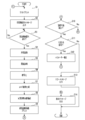
- FIG. 2 is a flowchart illustrating an example of the procedure of image quality management processing in the image forming apparatus according to the embodiment.
- FIG. 3 is a diagram showing an example of a test image output by the image forming apparatus according to the embodiment.
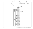
- FIG. 4 is a diagram showing an example of a diagnostic image output by the image forming apparatus according to the embodiment.
- the image forming apparatus 10 includes a printing device 1 and an image reading device 2.
- the image forming apparatus 10 is a copying machine or a multifunction machine.
- the printing apparatus 1 executes print processing for forming an image on the sheet 91.
- the image reading device 2 executes an image reading process of reading an image from the original 92.
- an image formed on the sheet 91 by the printing process of the printing apparatus 1 is called a print image.
- An image read from the original 92 by the image reading process of the image reading device 2 is referred to as a read image.
- the image forming apparatus 10 can communicate with a host device (not shown) via a network such as a LAN (Local Area Network).
- the host device is a computer that can communicate with the image forming apparatus 10.
- the image forming apparatus 10 includes a user interface device 3, a communication device 4 and a control device 5 in addition to the printing device 1 and the image reading device 2.
- the control device 5 also includes a print engine 50, a CPU 51, a RAM (Random Access Memory) 52, a secondary storage device 53, and the like.
- the user interface device 3 includes an operation device 3a and a display device 3b.
- the operation device 3a is a device that receives a user operation, and includes, for example, operation buttons and a touch panel.
- the display device 3b includes a display panel such as a liquid crystal panel that can display images and other information.
- the communication device 4 is a communication interface device that communicates with the host device through the network.
- the control device 5 performs all transmission and reception of data with the host device through the communication device 4.
- the printing apparatus 1 executes the print job by a predetermined method such as an electrophotographic method or an inkjet method.
- the printing apparatus 1 can execute the printing process based on the read image data or a print request received from the host apparatus through the communication apparatus 4.
- the printing apparatus 1 executes the print processing by the electrophotographic method.
- the printing apparatus 1 includes a sheet conveying mechanism 1a, a photoconductor 1b, a charging device 1c, a laser scanning unit 1d, a developing device 1e, a transfer device 1f, a fixing device 1g, and the like.
- the sheet conveying mechanism 1a conveys the sheet 91 along a predetermined route.
- the charging device 1c charges the surface of the photoconductor 1b.
- the laser scanning unit 1d writes an electrostatic latent image on the surface of the charged photoreceptor 1b.
- the developing device 1e develops the electrostatic latent image on the photoconductor 1b into a toner image.
- the transfer device 1f transfers the toner image on the photoconductor 1b onto the sheet 91.
- Toner is an example of a developer.
- the printing device 1 When the printing device 1 is a device capable of forming a color image on the sheet 91, the printing device 1 includes a plurality of image forming devices (not shown) that generate toner images of different colors. Each of the image forming devices includes a photoconductor 1b, a charging device 1c, and a developing device 1e.
- the transfer device 1f includes an endless intermediate transfer belt, a plurality of primary transfer devices corresponding to the plurality of photoconductors 1b, and a secondary transfer device.
- the plurality of primary transfer devices form a color toner image on the intermediate transfer belt by transferring the toner images on the plurality of photoconductors 1b onto the surface of the intermediate transfer belt.
- the plurality of primary transfer devices may transfer the monochromatic toner image from the photoconductor 1b onto the intermediate transfer belt.
- the secondary transfer device transfers the monochromatic toner image or the color toner image on the intermediate transfer belt onto the sheet 91.
- the fixing device 1g heats the monochromatic toner image or the color toner image on the sheet 91 to fix the toner image on the sheet 91.
- the image reading device 2 includes a light source 2a, a scanning mechanism 2b, an image sensor 2c, an AFE (Analog Front End) 2d, and the like.
- the control device 5 executes various calculations, data processing, and control of various electric devices included in the image forming apparatus 10.
- the control device 5 can exchange data and control signals with the printing device 1, the image reading device 2, the user interface device 3, and the communication device 4.
- the print engine 50 controls the printing device 1 in accordance with a command from the CPU 51 to cause the printing device 1 to execute the printing process.
- the print engine 50 is an example of a print controller.
- the print engine 50 is realized by a processor such as an MPU (Micro Processing Unit) or DSP (Digital Signal Processor) (not shown), or a circuit such as an ASIC (Application Specific Integrated Circuit).
- a processor such as an MPU (Micro Processing Unit) or DSP (Digital Signal Processor) (not shown), or a circuit such as an ASIC (Application Specific Integrated Circuit).
- the secondary storage device 53 is a computer-readable non-volatile storage device.
- the secondary storage device 53 can store a computer program and various data.
- a hard disk drive and an SSD (Solid State Drive) is adopted as the secondary storage device 53.
- RAM 52 is a computer-readable volatile storage device.
- the RAM 52 temporarily stores the computer program executed by the CPU 51 and the data output and referenced in the process of executing the computer program by the CPU 51.
- the CPU 51 is a processor that executes various types of data processing and control by executing the computer program stored in the secondary storage device 53. It is also conceivable that another processor such as a DSP executes the data processing and control instead of the CPU 51.
- the CPU 51 operates as the main control unit 5a, the print control unit 5b, the reading control unit 5c, and the like by executing the computer program.
- main control unit 5a controls the display device 3b to display various notification screens or operation screens on the display device 3b.
- the print control unit 5b supplies the print processing target data designated in the print request or the read image data to the print engine 50, and causes the printing apparatus 1 to execute the print processing through the print engine 50.
- the reading control unit 5c controls the image reading device 2 to cause the image reading device 2 to execute the image reading process.
- the image forming apparatus 10 has an image quality diagnosis function of diagnosing the image quality of the print image and outputting information of the diagnosis result, as described later.
- the image quality diagnosis function contributes to appropriately correcting the print parameters used in the print processing, and thus contributes to maintaining the print quality appropriately.
- an operator such as a repairman of the image forming apparatus 10 can quickly and appropriately adjust the print parameters by checking the print image and the print parameter information when the diagnosis result of the image quality defect is obtained. In many cases.
- the image forming apparatus 10 has a function of transmitting the diagnostic result of the image quality and the information of the print image and the print parameter when the diagnostic result is obtained to the management device or the like accessible by the worker. If so, the workability of the worker is improved.
- the image forming apparatus 10 may not be connected to the Internet or an open communication network such as a public line. In this case, the image forming apparatus 10 cannot send the print parameter information and the like to the management apparatus and the like.
- the print parameter information such as the developing bias or the transfer bias is confidential information for the maker of the image forming apparatus 10. It is desirable that such confidential information is not easily known to the user.
- the image forming apparatus 10 executes an image quality management process described later. As a result, the image forming apparatus 10 diagnoses the image quality of the print image without using an open communication network and avoids disclosure of confidential information to the user, while avoiding disclosure of confidential information to the user. It is possible to output parameter information.
- the CPU 51 By executing the computer program, the CPU 51 also operates as an image quality diagnosis unit 5d, an encryption unit 5e, a code image generation unit 5f, and a parameter correction unit 5g.
- the main control unit 5a starts the image quality management process when it detects that a predetermined image quality management start operation has been performed on the operation device 3a.
- Step S1> In the image quality management process, first, the print control unit 5b executes the process of step S1 and shifts the process to step S2.
- step S1 the print control unit 5b causes the printing apparatus 1 to execute a test print process of forming a predetermined test image G1 on the sheet 91 through the print engine 50 (see FIG. 3).
- the test image G1 is an image used for diagnosis of the image quality of the print image.
- the test image G1 includes a plurality of single color test images G11 for diagnosing the image quality relating to the development fog and the image density for each toner color.
- Each of the monochromatic test images G11 is an image of toner of one color.
- test image G1 shown in FIG. 3 further includes one or more composite color test images G12 for diagnosing a color misregistration situation of a color image in which toner images of a plurality of colors are composited.
- a plurality of single color test images G11 of the same color and a plurality of composite color test images G12 are arranged in different areas in the output image.
- step S1 the print control unit 5b causes the printing apparatus 1 to execute the process of forming the sheet 91 of the first date / time image G2 and the first identification image G3 together with the test image G1 in the test print process.
- the first date and time image G2 represents information on the date and time when the test print process is executed.
- the first identification image G3 represents identification information of the test print process.
- the print control unit 5b that executes the process of step S1 is an example of a test print control unit that causes the printing apparatus 1 to execute the test print process of forming a predetermined test image G1 on the sheet 91.
- step S2 the main controller 5a causes the display device 3b to output a predetermined printed matter reading message, and shifts the processing to step S3.
- the printed matter reading message is a message urging that the printed matter obtained by the test print processing is set in the image reading device 2 and a predetermined reading start operation is performed on the operating device 3a.
- the reading start operation is an operation for causing the image reading device 2 to start the image reading process.
- the printed matter obtained by the test print processing is the sheet 91 on which the test image G1 is formed. Further, the printed matter set by the user on the image reading device 2 in accordance with the process of step S2 is the original 92 on which the test image G1 is formed by the test print process.
- step S3 the main control unit 5a waits until it detects that the reading start operation is performed on the operating device 3a, and when the reading start operation is detected, shifts the processing to step S4.
- step S4 the reading control unit 5c causes the image reading device 2 to execute the image reading process, and shifts the process to step S5. As a result, the image reading device 2 reads the test image G1 from the original 92.
- step S5 the image quality diagnostic unit 5d executes an image quality diagnostic process for diagnosing the image quality of the test image G1 included in the read image obtained by the image reading device 2 in step S4, and shifts the process to step S6.
- the image quality diagnostic unit 5d compares the average density of a plurality of pixels in each of the single color test images G11 with a predetermined target density range, and thereby the image density defect or insufficient image quality defect for each toner color is obtained. It is determined whether or not has occurred.
- the image quality diagnosis unit 5d determines whether or not there is a color misregistration image quality defect by comparing the pixel position for each toner color in the composite color test image G12 with a predetermined target position range. .
- the image quality diagnosis unit 5d determines which of the plurality of single color test images G11 for each color of toner and the plurality of combined color test images G12 has the image quality defect, thereby causing the image quality defect. Identify the location.
- step S6 the encryption unit 5e encrypts the information of the one or more print parameters used in the test print processing by a predetermined method, and shifts the processing to step S7.
- the print parameters include the charging voltage supplied to the charging device 1c, the output timing of laser light in the laser scanning unit 1d, the developing bias voltage supplied to the developing device 1e or the transfer bias voltage supplied to the transfer device 1f. Control parameters that control the
- step S7 the code image generation unit 5f generates one or more code images G41 representing information on the one or more print parameters used in the test print processing (see FIG. 4). After that, the code image generation unit 5f shifts the processing to step S8.
- the code image G41 shown in FIG. 4 is an image of a two-dimensional code such as a QR code (registered trademark).
- the code image G41 may be a one-dimensional code image such as a barcode.
- step S8 the print control unit 5b executes the process of organizing the diagnostic image G4 as shown in FIG. 4, for example, and then shifts the process to step S9.
- the diagnostic image G4 includes a diagnostic result image G42 representing the diagnostic result of the image quality of the test image G1 obtained in step S5, and a code image G41 generated in step S7.
- the diagnosis result image G42 may be a character string image representing the diagnosis result of the image quality of the test image.
- step S8 the print control unit 5b organizes a diagnostic image G4 including a second date / time image G5 and a second identification image G6 in addition to the code image G41 and the diagnostic result image G42.
- the second date and time image G5 represents information on the date and time when the diagnostic image G4 is output in the next step S9.
- the second identification image G6 represents identification information of the test print process in which the print parameter represented by the code image G41 is adopted. That is, the second identification image G6 represents the same information as the first identification image G3 formed on the sheet 91 in step S1.
- the test image G1 formed on the sheet 91 in the test printing process and the second identification image G6 formed on the sheet 91 in the next step S9 the test image G1, the code image G41, and the diagnostic image are obtained. The correspondence with the result image G42 can be confirmed.
- step S9 the print control unit 5b causes the printing apparatus 1 to execute the process of forming the diagnostic image G4 on the sheet 91 through the print engine 50 (see FIG. 4). After that, the print control unit 5b shifts the processing to step S10.
- the image quality diagnostic unit 5d may detect an image quality defect in the single color test image G11 or the composite color test image G12 in a specific region of the test image G1, and may not detect the image quality defect in other regions.
- the print control unit 5b causes the printing apparatus 1 to execute the process of forming the diagnostic image G4 in a region different from the region where the image quality defect is detected in the print region of the sheet 91. This prevents the diagnostic image G4 from being output in the poor image quality state.
- the print control unit 5b causes the printing apparatus 1 to perform a process of forming the diagnostic image G4 in a predetermined area of the sheet 91.
- the image quality diagnosis unit 5d may detect the image quality defect in a specific color of the plurality of development colors in the test image G1.
- the development color is the color of toner.
- the print control unit 5b causes the printing apparatus 1 to perform a process of forming the diagnostic image G4 with a color different from the color in which the image quality defect is detected, of the plurality of development colors. This prevents the diagnostic image G4 from being output in the poor image quality state.
- the image quality diagnosis unit 5d may detect the image quality defect due to the development fog in the test image G1.
- the development fog is a phenomenon in which pixels that should not be originally developed are developed.
- the print control unit 5b causes the printing apparatus 1 to execute a process of forming a large diagnostic image G4 with a lower resolution than when the defective image quality due to the development fog is not detected.
- the code image G41 is formed on the sheet 91 in a large size with a low resolution, the reading error is less likely to occur.
- the diagnostic image G4 may not fit on one sheet 91, and the diagnostic image G4 may need to be formed separately on a plurality of sheets 91.
- the print controller 5b performs the process of forming the diagnostic image G4 on the sheet 91 in different output modes according to the content of the image quality defect detected in the image quality diagnosis of the test image G1. To run.
- the printing apparatus 1 that forms the diagnostic image G4 on the sheet 91 in step S9 is an example of an output device that outputs the diagnostic image G4.
- the print control unit 5b that executes the process of step S9 is an example of an output control unit that causes the printing apparatus 1 to output the diagnostic image G4.
- step S10 the image quality diagnosis unit 5d selects the next process according to the result of the image quality diagnosis process of step S5. That is, the image quality diagnostic unit 5d shifts the process to step S11 when the image quality defect is detected in the image quality diagnostic process, and shifts the process to step S14 when the image quality defect is not detected.
- step S11 the image quality diagnosis unit 5d determines whether the latest diagnosis result of the image quality defect is the result of the first image quality diagnosis process in the image quality management process this time.
- the image quality diagnostic unit 5d shifts the process to step S12 when determining that the latest diagnostic result of the image quality defect is the result of the first image quality diagnostic process, and otherwise, the process proceeds to step S13. Shift to.
- step S12 the parameter correction unit 5g automatically executes a parameter correction process for correcting the print parameter according to the diagnosis result of the image quality of the test image G1 and shifts the process to step S1.
- the process of step S12 is executed when the image quality of the test image G1 is diagnosed and an image quality defect is detected.
- the parameter correction unit 5g sets the parameter for controlling the amplitude or frequency of the AC component in the charging voltage supplied to the charging device 1c to the amplitude or the frequency. Is corrected so that
- the parameter correction unit 5g corrects the parameter that controls the output timing of the laser light in the laser scanning unit 1d.
- the parameter correction unit 5g corrects the print parameter for each toner color for the image quality defect detected for each toner color.
- step S12 When the process of step S12 is executed, the test print process in which the corrected print parameters are adopted is executed in step S1, and the processes of steps S2 to S10 corresponding to the test print process are executed again.
- the code image generation unit 5f executes the process of step S7 twice.
- the code image generation unit 5f generates a code image G41 for each of the print parameter information before correction and the print parameter information after correction corresponding to the diagnosis result of the image quality of the test image G1.
- step S13 the main controller 5a executes a process of outputting a predetermined error message to the display device 3b, and ends the image quality management process.
- the error message is a message urging that the printed matter of the test image G1 obtained in the process of step S1 and the printed matter of the diagnostic image G4 obtained in the process of step S9 are stored and contacted to a predetermined service center. is there.
- step S14 the main control unit 5a executes a process of outputting a predetermined good message to the display device 3b, and ends the image quality management process.
- the good message is a message telling that the result of the image quality diagnosis process is good.
- the image forming apparatus 10 diagnoses the image quality of the test image G1 which is an example of the print image, and the code image representing the print result information together with the diagnosis result used for printing the test image G1.
- G41 is output by the printing apparatus 1.
- test image G1 and the print parameter information corresponding to the test image G1 are output in a manner that can be transmitted to a specific worker such as the repairman. To be done.
- the print parameter information is output as the code image G41, disclosure of confidential information to the user is avoided.
- the code image G41 is a general-purpose code such as a QR code (registered trademark)
- the code image G41 representing the encrypted print parameter information is generated, so that confidential information for the user can be protected. Disclosure is avoided.
- a worker such as the repairman can confirm the print parameter information using a terminal device that converts the code image G41 into character string information.
- the terminal device includes a camera that captures the code image G41 and an image processing device that processes the code image G41 captured by the camera.
- the image processing apparatus includes a code restoration unit that restores the code image G41 into character string information, and a decryption unit that decrypts the character string information into information before encryption.
- step S6 of encrypting the print parameter information is omitted. Even in this case, the user cannot recognize the print parameter information only by looking at the diagnostic image G4.
- step S9 in FIG. 2 is a process in which the main control unit 5a outputs the diagnostic image G4 to the display device 3b.
- the display device 3b is an example of an output device that outputs an image.
- the main controller 5a is an example of an output controller that causes the output device to output the diagnostic image G4.
- the image forming apparatus 10 does not include the parameter correction unit 5g. That is, in the image quality management process shown in FIG. 2, the processes of steps S11 and S12 are omitted.
- step S10 when the image quality defect is detected, the process proceeds from step S10 to step S13.
- the image forming apparatus 10 does not automatically execute the parameter correction process, and a specific operator such as the repairman adjusts the print parameter while referring to the test image G1 and the diagnostic image G4.
- the diagnosis result image G42 was a character string image representing the diagnosis result of the image quality of the test image G1 (see FIG. 4).
- step S7 of FIG. 2 the code image generation unit 5f in this application example generates a code image G41 that represents the character string information that represents the diagnostic result of the image quality of the test image G1 and the encrypted print parameter information. .
- the print control unit 5b causes the printing apparatus 1 to output an image representing the diagnosis result of the image quality of the test image G1 as the code image G41 in step S9 of FIG. This prevents the user from easily recognizing the information about the diagnostic result of the image quality of the test image G1. Moreover, more information can be efficiently recorded in the limited print area of the sheet 91.
- the code image generation unit 5f in this application example determines the image quality defect detected by the diagnosis of the image quality of the test image G1 among the plurality of print parameter information adopted in the test print processing.
- the code image G41 is generated only for the corresponding partial information.
- the correspondence between the print parameter information and the poor image quality is predetermined.
- the number of generated code images G41 can be reduced.
Landscapes
- Engineering & Computer Science (AREA)
- Physics & Mathematics (AREA)
- General Physics & Mathematics (AREA)
- Microelectronics & Electronic Packaging (AREA)
- Quality & Reliability (AREA)
- Computer Vision & Pattern Recognition (AREA)
- Theoretical Computer Science (AREA)
- Multimedia (AREA)
- Signal Processing (AREA)
- Control Or Security For Electrophotography (AREA)
- Facsimiles In General (AREA)
- Accessory Devices And Overall Control Thereof (AREA)
Abstract
本発明の目的は、オープンな通信網を用いずに、プリント画像の画質を診断し、ユーザーへの機密情報の開示を回避し、プリント画像、画質の診断結果およびプリントパラメーターの情報を出力することにある。テストプリント制御部(S1,5b)は、テスト画像をシートに形成するテストプリント処理をプリント装置(2)に実行させる。画質診断部(5d)は、画像読取装置により得られる読取画像に含まれる前記テスト画像の画質を診断する。コード画像生成部(5f)は、前記テストプリント処理で採用されたプリントパラメーターの情報を表すコード画像を生成する。出力制御部(S9,5b)は、前記テスト画像の画質の診断結果を表す画像と前記コード画像とを含む診断画像を出力装置に出力させる。
Description
本発明は、プリント画質を診断する機能を備える画像形成装置に関する。
複写機、ファクシミリ装置または複合機などの画像形成装置は、シートに画像を形成するプリント装置と、原稿から画像を読み取る画像読取装置と、を備える。
また、前記複写機が、自装置の故障を診断し、診断結果を表すデータをホストコンピューターへ電子メールとして送信することが知られている(例えば、特許文献1参照)。
ところで、前記画像形成装置が、プリント画像の画質を診断し、診断結果の情報を出力する画質診断機能を備える場合がある。前記画質診断機能は、プリントパラメーターを適切に補正することに寄与し、ひいてはプリント品質を適切に維持することに寄与する。
例えば、前記画像形成装置の修理員などの作業者は、画質不良の診断結果が得られるときの前記プリント画像および前記プリントパラメーターの情報を確認することにより、前記プリントパラメーターを速やかに適切に調整できる場合が多い。
従って、前記画像形成装置が、画質の診断結果と、その診断結果が得られるときの前記プリント画像および前記プリントパラメーターの情報とを、前記作業者がアクセス可能な管理装置等へ送信する機能を備えていれば、前記作業者の作業性が向上する。
しかしながら、前記画像形成装置がインターネットまたは公衆回線などオープンな通信網に接続されていない場合がある。この場合、前記画像形成装置は、前記プリントパラメーターの情報などを前記管理装置等へ送信できない。
一方、現像バイアスまたは転写バイアスなどの前記プリントパラメーターの情報は、前記画像形成装置のメーカーにとって機密情報である。そのような機密情報は、外部に容易に知られないことが望ましい。
本発明の目的は、オープンな通信網を用いずに、プリント画像の画質を診断し、ユーザーへの機密情報の開示を回避しつつ、プリント画像、画質の診断結果およびプリントパラメーターの情報を出力することが可能な画像形成装置を提供することにある。
本発明の一の局面に係る画像形成装置は、プリント装置と、画像読取装置と、テストプリント制御部と、画質診断部と、コード画像生成部と、出力制御部と、を備える。前記プリント装置は、シートに画像を形成する。前記画像読取装置は、原稿から画像を読み取る。前記テストプリント制御部は、予め定められたテスト画像を前記シートに形成するテストプリント処理を前記プリント装置に実行させる。前記画質診断部は、前記画像読取装置により得られる読取画像に含まれる前記テスト画像の画質を診断する。前記コード画像生成部は、前記テストプリント処理で採用されたプリントパラメーターの情報を表すコード画像を生成する。前記出力制御部は、前記テスト画像の画質の診断結果を表す画像と前記コード画像とを含む診断画像を出力装置に出力させる。
本発明によれば、オープンな通信網を用いずに、プリント画像の画質を診断し、ユーザーへの機密情報の開示を回避しつつ、プリント画像、画質の診断結果およびプリントパラメーターの情報を出力することが可能な画像形成装置を提供することが可能になる。
以下、図面を参照しながら、本発明の実施形態について説明する。なお、以下の実施形態は、本発明を具体化した一例であって、本発明の技術的範囲を限定するものではない。
[画像形成装置10の構成]
本発明の実施形態に係る画像形成装置10は、プリント装置1および画像読取装置2を備える。例えば、画像形成装置10は、複写機または複合機などである。
本発明の実施形態に係る画像形成装置10は、プリント装置1および画像読取装置2を備える。例えば、画像形成装置10は、複写機または複合機などである。
プリント装置1は、シート91に画像を形成するプリント処理を実行する。画像読取装置2は、原稿92から画像を読み取る画像読取処理を実行する。
以下の説明において、プリント装置1の前記プリント処理によってシート91に形成される画像のことをプリント画像と称する。また、画像読取装置2の前記画像読取処理によって原稿92から読み取られた画像のことを読取画像と称する。
画像形成装置10は、LAN(Local Area Network)などのネットワークを通じて、不図示のホスト装置と通信可能である。前記ホスト装置は、画像形成装置10と通信可能なコンピューターである。
図1に示されるように、画像形成装置10は、プリント装置1および画像読取装置2に加え、ユーザーインターフェイス装置3、通信装置4および制御装置5などを備える。
また、制御装置5は、プリントエンジン50、CPU51、RAM(Random Access Memory)52および二次記憶装置53などを含む。
ユーザーインターフェイス装置3は、操作装置3aおよび表示装置3bなどを含む。操作装置3aは、ユーザーの操作を受け付ける装置であり、例えば操作ボタンおよびタッチパネルなどを含む。表示装置3bは、画像およびその他の情報を表示可能な液晶パネルなどの表示パネルを含む。
通信装置4は、前記ネットワークを通じて前記ホスト装置との間で通信を行う通信インターフェイスデバイスである。制御装置5は、前記ホスト装置との間のデータの送信および受信の全てを、通信装置4を通じて行う。
プリント装置1は、電子写真方式またはインクジェット方式などの予め定められた方式で前記プリントジョブを実行する。本実施形態において、プリント装置1は、前記読取画像のデータまたは通信装置4を通じて前記ホスト装置から受信されるプリント要求に基づいて前記プリント処理を実行可能である。
本実施形態において、プリント装置1は、電子写真方式で前記プリント処理を実行する。この場合、プリント装置1は、シート搬送機構1a、感光体1b、帯電装置1c、レーザースキャニングユニット1d、現像装置1e、転写装置1fおよび定着装置1gなどを備える。
シート搬送機構1aは、予め定められた経路に沿ってシート91を搬送する。帯電装置1cは、感光体1bの表面を帯電させる。レーザースキャニングユニット1dは、帯電した感光体1bの表面に静電潜像を書き込む。
現像装置1eは、感光体1b上の前記静電潜像をトナー像へ現像する。転写装置1fは、感光体1b上の前記トナー像をシート91に転写する。トナーは、現像剤の一例である。
プリント装置1が、シート91にカラー画像を形成可能な装置である場合、プリント装置1は、それぞれ異なる色のトナー像を生成する不図示の複数の作像装置を備える。前記作像装置各々は、感光体1b、帯電装置1cおよび現像装置1eを含む。
さらに、転写装置1fは、無端の中間転写ベルトと、複数の感光体1bに対応する複数の一次転写装置と、二次転写装置とを備える。前記複数の一次転写装置は、複数の感光体1b上の前記トナー像を前記中間転写ベルトの表面へ転写することにより、前記中間転写ベルト上にカラートナー画像を形成する。なお、前記複数の一次転写装置は、単色の前記トナー像を感光体1bから前記中間転写ベルト上へ転写する場合もある。
前記二次転写装置は、前記中間転写ベルト上の単色の前記トナー像または前記カラートナー像をシート91へ転写する。定着装置1gは、シート91上の単色の前記トナー像または前記カラートナー像を加熱し、シート91に定着させる。
画像読取装置2は、光源2a、走査機構2b、イメージセンサー2cおよびAFE(Analog Front End)2dなどを備える。
光源2aは、原稿92に対して光を出射する。走査機構2bは、光源2aの光を原稿92に対して走査させる。イメージセンサー2cは、原稿92からの反射光を受光し、受光量の検出信号を画像信号として出力する。AFE(2d)は、アナログの前記画像信号をデジタルの画像データへ変換する。
制御装置5は、各種の演算、データ処理および画像形成装置10が備える各種の電気機器の制御を実行する。制御装置5は、プリント装置1、画像読取装置2、ユーザーインターフェイス装置3および通信装置4との間でデータおよび制御信号の受け渡しが可能である。
プリントエンジン50は、CPU51からの指令に従ってプリント装置1を制御することにより、プリント装置1に前記プリント処理を実行させる。なお、プリントエンジン50は、プリント制御部の一例である。
プリントエンジン50は、不図示のMPU(Micro Processing Unit)もしくはDSP(Digital Signal Processor)などのプロセッサー、またはASIC(Application Specific Integrated Circuit)などの回路によって実現される。
二次記憶装置53は、コンピューター読み取り可能な不揮発性の記憶装置である。二次記憶装置53は、コンピュータープログラムおよび各種のデータを記憶可能である。例えば、ハードディスクドライブおよびSSD(Solid State Drive)の一方または両方の組
合せが、二次記憶装置53として採用される。
合せが、二次記憶装置53として採用される。
RAM52は、コンピューター読み取り可能な揮発性の記憶装置である。RAM52は、CPU51が実行する前記コンピュータープログラムおよびCPU51が前記コンピュータープログラムを実行する過程で出力および参照するデータを一次記憶する。
CPU51は、二次記憶装置53に記憶された前記コンピュータープログラムを実行することにより、各種のデータ処理および制御を実行するプロセッサーである。なお、DSPなどの他のプロセッサーが、CPU51の代わりに前記データ処理および制御を実行することも考えられる。
CPU51は、前記コンピュータープログラムを実行することにより、主制御部5a、プリント制御部5bおよび読取制御部5cなどとして動作する。
主制御部5aは、主として操作装置3aに対する操作および通信装置4によるデータ受信を監視し、操作またはデータ受信を検出したときに、検出内容に応じた処理の開始を制御する。
さらに、主制御部5aは、表示装置3bを制御し、表示装置3bに各種の通知画面または操作画面を表示させる。
プリント制御部5bは、前記プリント要求において指定される前記プリント処理の対象データ、または、前記読取画像のデータをプリントエンジン50に供給し、プリントエンジン50を通じてプリント装置1に前記プリント処理を実行させる。
読取制御部5cは、画像読取装置2を制御することにより、画像読取装置2に前記画像読取処理を実行させる。
ところで、画像形成装置10は、後述するように、前記プリント画像の画質を診断し、診断結果の情報を出力する画質診断機能を備える。前記画質診断機能は、前記プリント処理において採用されるプリントパラメーターを適切に補正することに寄与し、ひいてはプリント品質を適切に維持することに寄与する。
例えば、画像形成装置10の修理員などの作業者は、画質不良の診断結果が得られるときの前記プリント画像および前記プリントパラメーターの情報を確認することにより、前記プリントパラメーターを速やかに適切に調整できる場合が多い。
従って、画像形成装置10が、画質の診断結果と、その診断結果が得られるときの前記プリント画像および前記プリントパラメーターの情報とを、前記作業者がアクセス可能な管理装置等へ送信する機能を備えていれば、前記作業者の作業性が向上する。
しかしながら、画像形成装置10がインターネットまたは公衆回線などオープンな通信網に接続されていない場合がある。この場合、画像形成装置10は、前記プリントパラメーターの情報などを前記管理装置等へ送信できない。
一方、現像バイアスまたは転写バイアスなどの前記プリントパラメーターの情報は、画像形成装置10のメーカーにとって機密情報である。そのような機密情報は、ユーザーに容易に知られないことが望ましい。
本実施形態において、画像形成装置10は、後述する画質管理処理を実行する。これにより、画像形成装置10は、オープンな通信網を用いずに、前記プリント画像の画質を診断し、ユーザーへの機密情報の開示を回避しつつ、前記プリント画像、画質の診断結果および前記プリントパラメーターの情報を出力することが可能である。
CPU51は、前記コンピュータープログラムを実行することにより、さらに画質診断部5d、暗号化部5e、コード画像生成部5fおよびパラメーター補正部5gとしても動作する。
主制御部5aは、操作装置3aに対して予め定められた画質管理開始操作が行われたことを検出したときに、前記画質管理処理を開始する。
[画質管理処理]
以下、図2に示されるフローチャートを参照しつつ、前記画質管理処理の手順の一例について説明する。以下の説明において、S1,S2,…は、前記画質管理処理における複数の工程の識別符号を表す。
以下、図2に示されるフローチャートを参照しつつ、前記画質管理処理の手順の一例について説明する。以下の説明において、S1,S2,…は、前記画質管理処理における複数の工程の識別符号を表す。
<工程S1>
前記画質管理処理において、まず、プリント制御部5bが、工程S1の処理を実行し、処理を工程S2へ移行させる。
前記画質管理処理において、まず、プリント制御部5bが、工程S1の処理を実行し、処理を工程S2へ移行させる。
工程S1において、プリント制御部5bは、プリントエンジン50を通じて、予め定められたテスト画像G1をシート91に形成するテストプリント処理をプリント装置1に実行させる(図3参照)。
図3に示される例において、テスト画像G1は、前記プリント画像の画質の診断に用いられる画像である。図3に示される例において、テスト画像G1は、トナーの色ごとに現像かぶりおよび画像の濃度に関する画質を診断するための複数の単色テスト画像G11を含む。単色テスト画像G11各々は、一色のトナーの画像である。
さらに、図3に示されるテスト画像G1は、複数の色のトナー像が合成されたカラー画像の色ズレの状況を診断するための1つ以上の合成色テスト画像G12をさらに含む。
また、図3に示されるテスト画像G1は、同じ色の複数の単色テスト画像G11と、複数の合成色テスト画像G12とが、出力画像における異なる領域に配置されている。
さらに、工程S1において、プリント制御部5bは、前記テストプリント処理において、テスト画像G1とともに、第1日時画像G2および第1識別画像G3をシート91形成する処理をプリント装置1に実行させる。第1日時画像G2は、前記テストプリント処理が実行される日時の情報を表す。第1識別画像G3は、当該テストプリント処理の識別情報を表す。
なお、工程S1の処理を実行するプリント制御部5bは、予め定められたテスト画像G1をシート91に形成する前記テストプリント処理をプリント装置1に実行させるテストプリント制御部の一例である。
<工程S2>
工程S2において、主制御部5aが、予め定められた印刷物読取メッセージを表示装置3bに出力させ、処理を工程S3へ移行させる。
工程S2において、主制御部5aが、予め定められた印刷物読取メッセージを表示装置3bに出力させ、処理を工程S3へ移行させる。
前記印刷物読取メッセージは、前記テストプリント処理により得られる印刷物を画像読取装置2にセットし、予め定められた読取開始操作を操作装置3aに対して行うことを促すメッセージである。前記読取開始操作は、画像読取装置2に前記画像読取処理を開始させるための操作である。
前記テストプリント処理により得られる印刷物は、テスト画像G1が形成されたシート91である。また、工程S2の処理に応じてユーザーが画像読取装置2にセットする前記印刷物は、前記テストプリント処理によりテスト画像G1が形成された原稿92である。
<工程S3>
工程S3において、主制御部5aは、操作装置3aに対して前記読取開始操作が行われることを検出するまで待機し、前記読取開始操作を検出したときに、処理を工程S4へ移行させる。
工程S3において、主制御部5aは、操作装置3aに対して前記読取開始操作が行われることを検出するまで待機し、前記読取開始操作を検出したときに、処理を工程S4へ移行させる。
<工程S4>
工程S4において、読取制御部5cが、画像読取装置2に前記画像読取処理を実行させ、処理を工程S5へ移行させる。これにより、画像読取装置2が、原稿92からテスト画像G1を読み取る。
工程S4において、読取制御部5cが、画像読取装置2に前記画像読取処理を実行させ、処理を工程S5へ移行させる。これにより、画像読取装置2が、原稿92からテスト画像G1を読み取る。
<工程S5>
工程S5において、画質診断部5dが、工程S4において画像読取装置2により得られる前記読取画像に含まれるテスト画像G1の画質を診断する画質診断処理を実行し、処理を工程S6へ移行させる。
工程S5において、画質診断部5dが、工程S4において画像読取装置2により得られる前記読取画像に含まれるテスト画像G1の画質を診断する画質診断処理を実行し、処理を工程S6へ移行させる。
例えば、画質診断部5dは、単色テスト画像G11各々における複数の画素の平均濃度と予め定められた目標濃度範囲とを比較することにより、トナーの色ごとに前記濃度不足または前記濃度過剰の画質不良が生じているか否かを判定する。
さらに、画質診断部5dは、単色テスト画像G11各々における複数の画素の濃度のばらつき度合いと予め定めら得た許容ばらつき範囲とを比較することにより、トナーの色ごとに濃度ムラの画質不良が生じているか否かを判定する。
さらに、画質診断部5dは、合成色テスト画像G12におけるトナー色ごとの画素位置と予め定められた目標位置の範囲とを比較することにより、色ズレの画質不良が生じているか否かを判定する。
さらに、画質診断部5dは、トナーの色ごとの複数の単色テスト画像G11、および、複数の合成色テスト画像G12のいずれにおいて前記画質不良が生じているかを判定することにより、前記画質不良が生じている位置を特定する。
<工程S6>
工程S6において、暗号化部5eが、前記テストプリント処理で採用された1つ以上の前記プリントパラメーターの情報を予め定められた方式で暗号化し、処理を工程S7へ移行させる。
工程S6において、暗号化部5eが、前記テストプリント処理で採用された1つ以上の前記プリントパラメーターの情報を予め定められた方式で暗号化し、処理を工程S7へ移行させる。
例えば、前記プリントパラメーターは、帯電装置1cに供給される帯電電圧、レーザースキャニングユニット1dにおけるレーザー光の出力タイミング、現像装置1eに供給される現像バイアス電圧または転写装置1fに供給される転写バイアス電圧などを制御する制御パラメーターを含む。
<工程S7>
工程S7において、コード画像生成部5fが、前記テストプリント処理で採用された1つ以上の前記プリントパラメーターの情報を表す1つ以上のコード画像G41を生成する(図4参照)。その後、コード画像生成部5fは、処理を工程S8へ移行させる。
工程S7において、コード画像生成部5fが、前記テストプリント処理で採用された1つ以上の前記プリントパラメーターの情報を表す1つ以上のコード画像G41を生成する(図4参照)。その後、コード画像生成部5fは、処理を工程S8へ移行させる。
本実施形態において、コード画像生成部5fは、工程S6で暗号化された前記プリントパラメーターの情報を表すコード画像G41を生成する。
図4に示されるコード画像G41は、QRコード(登録商標)などの二次元コードの画像である。なお、コード画像G41が、バーコードなどの一次元コードの画像であることも考えられる。
<工程S8>
工程S8において、プリント制御部5bが、例えば図4に示されるような診断画像G4を編成する処理を実行した後、処理を工程S9へ移行させる。
工程S8において、プリント制御部5bが、例えば図4に示されるような診断画像G4を編成する処理を実行した後、処理を工程S9へ移行させる。
診断画像G4は、工程S5で得られるテスト画像G1の画質の診断結果を表す診断結果画像G42と、工程S7で生成されるコード画像G41とを含む。
例えば、図4に示されるように、診断結果画像G42が、前記テスト画像の画質の診断結果を表す文字列画像であることが考えられる。
さらに、工程S8において、プリント制御部5bは、コード画像G41および診断結果画像G42に加え、第2日時画像G5および第2識別画像G6を含む診断画像G4を編成する。第2日時画像G5は、次の工程S9で診断画像G4が出力される日時の情報を表す。
第2識別画像G6は、コード画像G41が表す前記プリントパラメーターが採用された前記テストプリント処理の識別情報を表す。即ち、第2識別画像G6は、工程S1においてシート91に形成される第1識別画像G3と同じ情報を表す。
前記テストプリント処理においてシート91に形成される第1識別画像G3と、次の工程S9においてシート91に形成される第2識別画像G6とを参照することにより、テスト画像G1とコード画像G41および診断結果画像G42との対応関係を確認することができる。
<工程S9>
工程S9において、プリント制御部5bが、プリントエンジン50を通じて、診断画像G4をシート91に形成する処理をプリント装置1に実行させる(図4参照)。その後、プリント制御部5bは、処理を工程S10へ移行させる。
工程S9において、プリント制御部5bが、プリントエンジン50を通じて、診断画像G4をシート91に形成する処理をプリント装置1に実行させる(図4参照)。その後、プリント制御部5bは、処理を工程S10へ移行させる。
前述の工程S5において、画質診断部5dが、テスト画像G1における特定の領域の単色テスト画像G11または合成色テスト画像G12について画質不良を検出し、その他の領域において画質不良が検出しない場合がある。
上記の場合、プリント制御部5bは、シート91のプリント領域における前記画質不良が検出された領域とは異なる領域に診断画像G4を形成する処理をプリント装置1に実行させる。これにより、診断画像G4が、前記画質不良の状態で出力されることが回避される。
なお、前記画質不良が特定の領域においてのみ検出されている状況ではない場合には、プリント制御部5bは、シート91における予め定められた領域に診断画像G4を形成する処理をプリント装置1に実行させる。
また、前述の工程S5において、画質診断部5dが、テスト画像G1において複数の現像色のうち特定の色について前記画質不良を検出する場合がある。本実施形態において、前記現像色はトナーの色である。
上記の場合、プリント制御部5bは、前記複数の現像色のうち前記画質不良が検出された色とは異なる色で診断画像G4を形成する処理をプリント装置1に実行させる。これにより、診断画像G4が、前記画質不良の状態で出力されることが回避される。
また、前述の工程S5において、画質診断部5dが、テスト画像G1において前記現像かぶりの画質不良を検出する場合がある。前記現像かぶりは、本来は現像されるべきでない画素が現像される現象である。
上記の場合、プリント制御部5bは、前記現像かぶりの画質不良が検出されない場合よりも低い解像度で大きく診断画像G4を形成する処理をプリント装置1に実行させる。
前記現像かぶりが生じている場合、コード画像G41が高解像度で小さくシート91に形成されると、コード画像G41がカメラなどを通じて読み取られる際に、読取エラーが生じやすい。
コード画像G41が低い解像度で大きくシート91に形成されることにより、前記読取エラーが生じにくくなる。但しこの場合、診断画像G4が1枚のシート91に収まらず、診断画像G4を複数のシート91に分けて形成する必要が生じる可能性がある。
以上に示されるように、プリント制御部5bは、テスト画像G1の画質の診断において検出される前記画質不良の内容に応じて異なる出力態様で診断画像G4をシート91に形成する処理をプリント装置1に実行させる。
工程S9において診断画像G4をシート91に形成するプリント装置1は、診断画像G4を出力する出力装置の一例である。また、工程S9の処理を実行するプリント制御部5bは、診断画像G4をプリント装置1に出力させる出力制御部の一例である。
<工程S10>
工程S10において、画質診断部5dが、工程S5の前記画質診断処理の結果に応じて次の処理を選択する。即ち、画質診断部5dは、前記画質診断処理において画質不良が検出された場合に処理を工程S11へ移行させ、前記画質不良が検出されない場合に処理を工程S14へ移行させる。
工程S10において、画質診断部5dが、工程S5の前記画質診断処理の結果に応じて次の処理を選択する。即ち、画質診断部5dは、前記画質診断処理において画質不良が検出された場合に処理を工程S11へ移行させ、前記画質不良が検出されない場合に処理を工程S14へ移行させる。
<工程S11>
工程S11において、画質診断部5dは、最新の前記画質不良の診断結果が今回の前記画質管理処理における1回目の前記画質診断処理の結果であるか否かを判定する。
工程S11において、画質診断部5dは、最新の前記画質不良の診断結果が今回の前記画質管理処理における1回目の前記画質診断処理の結果であるか否かを判定する。
そして、画質診断部5dは、最新の前記画質不良の診断結果が1回目の前記画質診断処理の結果であると判定する場合に、処理を工程S12へ移行させ、そうでない場合に処理を工程S13へ移行させる。
<工程S12>
工程S12において、パラメーター補正部5gが、テスト画像G1の画質の診断結果に応じて前記プリントパラメーターを補正するパラメーター補正処理を自動的に実行し、処理を工程S1へ移行させる。工程S12の処理は、テスト画像G1の画質の診断により画質不良が検出される場合に実行される。
工程S12において、パラメーター補正部5gが、テスト画像G1の画質の診断結果に応じて前記プリントパラメーターを補正するパラメーター補正処理を自動的に実行し、処理を工程S1へ移行させる。工程S12の処理は、テスト画像G1の画質の診断により画質不良が検出される場合に実行される。
例えば、前記濃度ムラの画質不良が検出されている場合に、パラメーター補正部5gは、帯電装置1cに供給される前記帯電電圧における交流成分の振幅または周波数を制御するパラメーターを、前記振幅または前記周波数が増大するように補正する。
また、前記色ズレの画質不良が検出されている場合に、パラメーター補正部5gは、レーザースキャニングユニット1dにおける前記レーザー光の前記出力タイミングを制御するパラメーターを補正する。
なお、パラメーター補正部5gは、トナーの色ごとに検出される画質不良については、トナーの色ごとに前記プリントパラメーターを補正する。
工程S12の処理が実行された場合、補正後の前記プリントパラメーターが採用される前記テストプリント処理が工程S1において実行され、そのテストプリント処理に対応する工程S2~S10の処理が再び実行される。
従って、工程S12の処理が実行される場合、コード画像生成部5fは、工程S7の処理を2回実行する。これにより、コード画像生成部5fは、テスト画像G1の画質の診断結果に対応する補正前の前記プリントパラメーターの情報および補正後の前記プリントパラメーターの情報のそれぞれについてコード画像G41を生成する。
<工程S13>
工程S13において、主制御部5aが、予め定められたエラーメッセージを表示装置3bに出力する処理を実行し、前記画質管理処理を終了させる。
工程S13において、主制御部5aが、予め定められたエラーメッセージを表示装置3bに出力する処理を実行し、前記画質管理処理を終了させる。
例えば、前記エラーメッセージは、工程S1の処理で得られるテスト画像G1の印刷物および工程S9の処理で得られる診断画像G4の印刷物を保管し、予め定められたサービスセンターへ連絡することを促すメッセージである。
<工程S14>
工程S14において、主制御部5aが、予め定められた良好メッセージを表示装置3bに出力する処理を実行し、前記画質管理処理を終了させる。
工程S14において、主制御部5aが、予め定められた良好メッセージを表示装置3bに出力する処理を実行し、前記画質管理処理を終了させる。
例えば、前記良好メッセージは、前記画質診断処理の結果が良好であった旨を伝えるメッセージである。
以上に示されるように、画像形成装置10は、前記プリント画像の一例であるテスト画像G1の画質を診断し、診断結果とともにテスト画像G1のプリントに採用された前記プリントパラメーターの情報を表すコード画像G41をプリント装置1によって出力する。
従って、画像形成装置10がオープンな通信網に接続されない場合でも、テスト画像G1およびテスト画像G1に対応する前記プリントパラメーターの情報が、前記修理員などの特定の作業者へ伝達可能な態様で出力される。
また、前記プリントパラメーターの情報がコード画像G41として出力されるため、ユーザーへの機密情報の開示が回避される。
また、コード画像G41が、QRコード(登録商標)のような汎用コードである場合でも、暗号化された前記プリントパラメーターの情報を表すコード画像G41が生成されることにより、ユーザーへの機密情報の開示が回避される。
一方、前記修理員などの作業者は、コード画像G41を文字列情報へ変換する端末装置を用いて前記プリントパラメーターの情報を確認することができる。
例えば、前記端末装置は、コード画像G41を撮影するカメラと、前記カメラにより撮影されたコード画像G41を処理する画像処理装置とを含む。前記画像処理装置は、コード画像G41を文字列情報へ復元するコード復元部と、前記文字列情報を暗号化前の情報へ復号する復号部とを含む。
なお、前記プリントパラメーターの情報を暗号化する工程S6の処理が省略されることも考えられる。この場合でも、ユーザーは、診断画像G4を見ただけでは前記プリントパラメーターの情報を認識することができない。
[第1応用例]
以下、画像形成装置10の第1応用例について説明する。
以下、画像形成装置10の第1応用例について説明する。
本応用例において、図2の工程S9の処理は、主制御部5aが診断画像G4を表示装置3bへ出力する処理である。この場合、表示装置3bが、画像を出力する出力装置の一例である。さらに、主制御部5aが、その出力装置に診断画像G4を出力させる出力制御部の一例である。
[第2応用例]
以下、画像形成装置10の第2応用例について説明する。
以下、画像形成装置10の第2応用例について説明する。
本応用例において、画像形成装置10は、パラメーター補正部5gを備えていない。即ち、図2に示される前記画質管理処理において、工程S11,S12の処理が省略される。
本応用例において、前記画質不良が検出された場合に、処理が工程S10から工程S13へ移行される。この場合、画像形成装置10は、前記パラメーター補正処理を自動的に実行せず、前記修理員などの特定の作業者が、テスト画像G1および診断画像G4を参照しつつ前記プリントパラメーターを調整する。
[第3応用例]
以下、画像形成装置10の第3応用例について説明する。
以下、画像形成装置10の第3応用例について説明する。
前述の実施形態では、診断結果画像G42は、テスト画像G1の画質の診断結果を表す文字列画像であった(図4参照)。
本応用例におけるコード画像生成部5fは、図2の工程S7において、テスト画像G1の画質の診断結果を表す文字列情報と暗号化された前記プリントパラメーターの情報とを表すコード画像G41を生成する。
また、プリント制御部5bは、図2の工程S9において、テスト画像G1の画質の診断結果を表す画像を、コード画像G41としてプリント装置1に出力させる。これにより、テスト画像G1の画質の診断結果の情報についても、ユーザーに容易に認識されることが回避される。また、より多くの情報を、限られたシート91のプリント領域内に効率的に記録することができる。
[第4応用例]
以下、画像形成装置10の第4応用例について説明する。
以下、画像形成装置10の第4応用例について説明する。
本応用例におけるコード画像生成部5fは、図2の工程S7において、前記テストプリント処理で採用された複数の前記プリントパラメーターの情報のうち、テスト画像G1の画質の診断により検出される画質不良に対応する一部の情報についてのみコード画像G41を生成する。前記プリントパラメーターの情報と画質不良との対応関係は予め定められている。
本応用例によれば、前記プリントパラメーターの情報量が、複数のコード画像G41を必要とするほど多い場合に、生成されるコード画像G41の数を減らすことができる。
Claims (10)
- シートに画像を形成するプリント装置と、
原稿から画像を読み取る画像読取装置と、
予め定められたテスト画像を前記シートに形成するテストプリント処理を前記プリント装置に実行させるテストプリント制御部と、
前記画像読取装置により得られる読取画像に含まれる前記テスト画像の画質を診断する画質診断部と、
前記テストプリント処理で採用されたプリントパラメーターの情報を表すコード画像を生成するコード画像生成部と、
前記テスト画像の画質の診断結果を表す画像と前記コード画像とを含む診断画像を出力装置に出力させる出力制御部と、を備える画像形成装置。 - 前記出力装置が前記プリント装置であり、
前記出力制御部は、前記テスト画像の画質の診断において検出される画質不良の内容に応じて異なる出力態様で前記診断画像を前記シートに形成する処理を前記プリント装置に実行させる、請求項1に記載の画像形成装置。 - 前記画質診断部が、前記テスト画像における特定の領域の画像について前記画質不良を検出した場合に、前記出力制御部は、前記シートのプリント領域における前記画質不良が検出された領域とは異なる領域に前記診断画像を形成する処理を前記プリント装置に実行させる、請求項2に記載の画像形成装置。
- 前記画質診断部が、前記テスト画像において複数の現像色のうち特定の色について前記画質不良を検出した場合に、前記出力制御部は、前記複数の現像色のうち前記画質不良が検出された色とは異なる色で前記診断画像を形成する処理を前記プリント装置に実行させる、請求項2に記載の画像形成装置。
- 前記画質診断部が、前記テスト画像において現像かぶりの前記画質不良を検出した場合に、前記出力制御部は、前記現像かぶりの前記画質不良が検出されない場合よりも低い解像度で大きく前記診断画像を形成する処理を前記プリント装置に実行させる、請求項2に記載の画像形成装置。
- 前記テスト画像の画質の診断により画質不良が検出される場合に、前記画質不良に対応する前記プリントパラメーターを補正するパラメーター補正部をさらに備え、
前記コード画像生成部は、前記テスト画像の画質の診断結果に対応する補正前の前記プリントパラメーターの情報および補正後の前記プリントパラメーターの情報のそれぞれについて前記コード画像を生成する、請求項1に記載の画像形成装置。 - 前記テストプリント処理で採用された前記プリントパラメーターの情報を暗号化する暗号化部をさらに備え、
前記コード画像生成部は、暗号化された前記プリントパラメーターの情報を表す前記コード画像を生成する、請求項1に記載の画像形成装置。 - 前記コード画像生成部は、前記テスト画像の画質の診断結果を表す文字列情報と暗号化された前記プリントパラメーターの情報とを表す前記コード画像を生成し、
前記出力制御部は、前記テスト画像の画質の診断結果を表す画像を、前記コード画像として前記出力装置に出力させる、請求項7に記載の画像形成装置。 - 前記出力制御部は、前記テスト画像の画質の診断結果を表す文字列画像と前記コード画像とを含む前記診断画像を前記出力装置に出力させる、請求項1に記載の画像形成装置。
- 前記コード画像生成部は、前記テストプリント処理で採用された前記プリントパラメーターの情報のうち、前記テスト画像の画質の診断により検出される画質不良に対応する一部の情報についてのみ前記コード画像を生成する、請求項1に記載の画像形成装置。
Priority Applications (2)
| Application Number | Priority Date | Filing Date | Title |
|---|---|---|---|
| JP2020519820A JP6908189B2 (ja) | 2018-10-24 | 2019-08-27 | 画像形成装置 |
| US16/759,530 US11126125B1 (en) | 2018-10-24 | 2019-08-27 | Image forming apparatus |
Applications Claiming Priority (2)
| Application Number | Priority Date | Filing Date | Title |
|---|---|---|---|
| JP2018-199794 | 2018-10-24 | ||
| JP2018199794 | 2018-10-24 |
Publications (1)
| Publication Number | Publication Date |
|---|---|
| WO2020084892A1 true WO2020084892A1 (ja) | 2020-04-30 |
Family
ID=70331305
Family Applications (1)
| Application Number | Title | Priority Date | Filing Date |
|---|---|---|---|
| PCT/JP2019/033497 Ceased WO2020084892A1 (ja) | 2018-10-24 | 2019-08-27 | 画像形成装置 |
Country Status (3)
| Country | Link |
|---|---|
| US (1) | US11126125B1 (ja) |
| JP (1) | JP6908189B2 (ja) |
| WO (1) | WO2020084892A1 (ja) |
Families Citing this family (4)
| Publication number | Priority date | Publication date | Assignee | Title |
|---|---|---|---|---|
| CN113950662A (zh) * | 2019-06-13 | 2022-01-18 | 惠普发展公司, 有限责任合伙企业 | 打印管理 |
| JP7541840B2 (ja) * | 2020-03-17 | 2024-08-29 | キヤノン株式会社 | 画像処理装置、画像処理方法及びプログラム |
| JP2024121457A (ja) * | 2023-02-27 | 2024-09-06 | 富士フイルムビジネスイノベーション株式会社 | 情報処理システムおよびプログラム |
| US12293242B2 (en) | 2023-09-28 | 2025-05-06 | Ricoh Company, Ltd. | Printer calibration mechanism |
Citations (6)
| Publication number | Priority date | Publication date | Assignee | Title |
|---|---|---|---|---|
| JP2007059975A (ja) * | 2005-08-22 | 2007-03-08 | Fuji Xerox Co Ltd | 画像処理システム、画像処理方法及びプログラム |
| US20080050133A1 (en) * | 2006-08-22 | 2008-02-28 | Xerox Corporation | System for initiating image-quality tests in a digital printer |
| JP2008152395A (ja) * | 2006-12-14 | 2008-07-03 | Canon Inc | 情報処理装置、情報処理装置の制御方法、画像形成装置及びコンピュータプログラム |
| JP2010004311A (ja) * | 2008-06-20 | 2010-01-07 | Konica Minolta Business Technologies Inc | 画像形成装置、管理システム及び管理方法 |
| JP2018132682A (ja) * | 2017-02-16 | 2018-08-23 | キヤノン株式会社 | 画像形成装置 |
| JP2018141898A (ja) * | 2017-02-28 | 2018-09-13 | 京セラドキュメントソリューションズ株式会社 | 画像形成装置 |
Family Cites Families (8)
| Publication number | Priority date | Publication date | Assignee | Title |
|---|---|---|---|---|
| JP2744708B2 (ja) * | 1991-03-11 | 1998-04-28 | シャープ株式会社 | 画像形成装置 |
| US5729350A (en) * | 1994-12-20 | 1998-03-17 | Canon Kabushiki Kaisha | Using information on an input sheet to change apparatus settings |
| US6031621A (en) * | 1996-11-05 | 2000-02-29 | Hewlett-Packard Company | Information collection system |
| JP2003067166A (ja) | 2001-08-27 | 2003-03-07 | Kyocera Mita Corp | 画像形成装置の管理システム、画像形成装置、ホストコンピュータ、プログラム及びコンピュータ読み取り可能な記録媒体 |
| US6985682B2 (en) * | 2001-10-17 | 2006-01-10 | Hewlett-Packard Development Company, Lp. | Media identification sheet |
| US8418913B2 (en) * | 2009-10-26 | 2013-04-16 | Xerox Corporation | Method and apparatus for generating and using an options enablement sheet to activate options on an image production device |
| JP2018132719A (ja) * | 2017-02-17 | 2018-08-23 | キヤノン株式会社 | 画像形成装置、画像形成装置の制御方法 |
| US10942687B2 (en) * | 2019-06-28 | 2021-03-09 | Ncr Corporation | Print quality monitoring and correction |
-
2019
- 2019-08-27 JP JP2020519820A patent/JP6908189B2/ja not_active Expired - Fee Related
- 2019-08-27 US US16/759,530 patent/US11126125B1/en not_active Expired - Fee Related
- 2019-08-27 WO PCT/JP2019/033497 patent/WO2020084892A1/ja not_active Ceased
Patent Citations (6)
| Publication number | Priority date | Publication date | Assignee | Title |
|---|---|---|---|---|
| JP2007059975A (ja) * | 2005-08-22 | 2007-03-08 | Fuji Xerox Co Ltd | 画像処理システム、画像処理方法及びプログラム |
| US20080050133A1 (en) * | 2006-08-22 | 2008-02-28 | Xerox Corporation | System for initiating image-quality tests in a digital printer |
| JP2008152395A (ja) * | 2006-12-14 | 2008-07-03 | Canon Inc | 情報処理装置、情報処理装置の制御方法、画像形成装置及びコンピュータプログラム |
| JP2010004311A (ja) * | 2008-06-20 | 2010-01-07 | Konica Minolta Business Technologies Inc | 画像形成装置、管理システム及び管理方法 |
| JP2018132682A (ja) * | 2017-02-16 | 2018-08-23 | キヤノン株式会社 | 画像形成装置 |
| JP2018141898A (ja) * | 2017-02-28 | 2018-09-13 | 京セラドキュメントソリューションズ株式会社 | 画像形成装置 |
Also Published As
| Publication number | Publication date |
|---|---|
| JPWO2020084892A1 (ja) | 2021-02-15 |
| US20210318650A1 (en) | 2021-10-14 |
| JP6908189B2 (ja) | 2021-07-21 |
| US11126125B1 (en) | 2021-09-21 |
Similar Documents
| Publication | Publication Date | Title |
|---|---|---|
| JP6908189B2 (ja) | 画像形成装置 | |
| US10686945B2 (en) | Diagnosis system, diagnosis method and storage medium | |
| US8508789B2 (en) | Determining a degree of fit between an image data input device and an image data output device | |
| JP6690232B2 (ja) | 画像処理装置、画像形成装置、画像処理方法及びプログラム | |
| JP5790285B2 (ja) | 画像形成装置 | |
| US8570545B2 (en) | Image forming apparatus having a plurality of image forming units, initial adjustment method for the image forming apparatus, and computer readable medium recording program for causing the image forming apparatus to perform initial adjustment | |
| US10798255B2 (en) | Image data generation apparatus, information processing system, image data generation method, and recording medium | |
| JP5565217B2 (ja) | 光書き込み装置、画像形成装置、および光書き込み制御方法 | |
| JP6558295B2 (ja) | 画像形成装置 | |
| JP7263844B2 (ja) | 画像形成装置、異常特定方法、異常特定プログラム及び異常特定システム | |
| JP2008145589A (ja) | 画像形成装置及び画像処理装置 | |
| JP2009230144A (ja) | 画像形成装置および画像形成方法 | |
| JP2008227559A (ja) | 画像形成装置及び画像形成方法 | |
| JP2012227621A (ja) | 画像形成装置、制御方法及び制御プログラム | |
| JP5932730B2 (ja) | 画像形成装置 | |
| JP2012034077A (ja) | 通信装置及びこれを備えた画像形成装置 | |
| JP2009265167A (ja) | カラー画像形成装置 | |
| JP7100486B2 (ja) | 画像形成装置 | |
| JP2006088521A (ja) | 画像出力装置、出力管理装置、出力管理方法及びそのプログラム | |
| JP4261556B2 (ja) | 印刷システム、及び情報処理装置 | |
| JP2007036330A (ja) | 画像処理システム、画像処理方法及びプログラム | |
| JP2011099907A (ja) | カラー画像形成システム | |
| JP2010050767A (ja) | 画像読取装置 | |
| JP4083750B2 (ja) | 画像形成装置および複合機 | |
| JP2007059972A (ja) | 画像処理装置、画像処理方法及びプログラム |
Legal Events
| Date | Code | Title | Description |
|---|---|---|---|
| ENP | Entry into the national phase |
Ref document number: 2020519820 Country of ref document: JP Kind code of ref document: A |
|
| 121 | Ep: the epo has been informed by wipo that ep was designated in this application |
Ref document number: 19877282 Country of ref document: EP Kind code of ref document: A1 |
|
| NENP | Non-entry into the national phase |
Ref country code: DE |
|
| 122 | Ep: pct application non-entry in european phase |
Ref document number: 19877282 Country of ref document: EP Kind code of ref document: A1 |