WO2020084655A1 - 内視鏡クリップ - Google Patents
内視鏡クリップ Download PDFInfo
- Publication number
- WO2020084655A1 WO2020084655A1 PCT/JP2018/039152 JP2018039152W WO2020084655A1 WO 2020084655 A1 WO2020084655 A1 WO 2020084655A1 JP 2018039152 W JP2018039152 W JP 2018039152W WO 2020084655 A1 WO2020084655 A1 WO 2020084655A1
- Authority
- WO
- WIPO (PCT)
- Prior art keywords
- arm
- arm member
- clip
- endoscope clip
- slider
- Prior art date
- Legal status (The legal status is an assumption and is not a legal conclusion. Google has not performed a legal analysis and makes no representation as to the accuracy of the status listed.)
- Ceased
Links
Images









Classifications
-
- A—HUMAN NECESSITIES
- A61—MEDICAL OR VETERINARY SCIENCE; HYGIENE
- A61B—DIAGNOSIS; SURGERY; IDENTIFICATION
- A61B17/00—Surgical instruments, devices or methods
- A61B17/12—Surgical instruments, devices or methods for ligaturing or otherwise compressing tubular parts of the body, e.g. blood vessels or umbilical cord
- A61B17/122—Clamps or clips, e.g. for the umbilical cord
- A61B17/1227—Spring clips
-
- A—HUMAN NECESSITIES
- A61—MEDICAL OR VETERINARY SCIENCE; HYGIENE
- A61B—DIAGNOSIS; SURGERY; IDENTIFICATION
- A61B17/00—Surgical instruments, devices or methods
- A61B17/12—Surgical instruments, devices or methods for ligaturing or otherwise compressing tubular parts of the body, e.g. blood vessels or umbilical cord
- A61B17/128—Surgical instruments, devices or methods for ligaturing or otherwise compressing tubular parts of the body, e.g. blood vessels or umbilical cord for applying or removing clamps or clips
- A61B17/1285—Surgical instruments, devices or methods for ligaturing or otherwise compressing tubular parts of the body, e.g. blood vessels or umbilical cord for applying or removing clamps or clips for minimally invasive surgery
-
- A—HUMAN NECESSITIES
- A61—MEDICAL OR VETERINARY SCIENCE; HYGIENE
- A61B—DIAGNOSIS; SURGERY; IDENTIFICATION
- A61B17/00—Surgical instruments, devices or methods
- A61B2017/00367—Details of actuation of instruments, e.g. relations between pushing buttons, or the like, and activation of the tool, working tip, or the like
- A61B2017/00407—Ratchet means
Definitions
- the present invention relates to an endoscopic clip used for ligating tissue.
- the endoscope treatment tool described in Patent Document 1 includes a clip unit and a treatment tool body.
- the clip unit has a clip body, a pressing tube, and a spiral spring.
- the clip body has a first arm and a second arm. The first arm and the second arm are separated from each other with a space between the tip of the first arm and the tip of the second arm when no external force is applied.
- the treatment instrument body has an outer tube, an insertion portion, and an operation member. The insertion portion is inserted into the outer tube so as to be able to move forward and backward, and has a sheath, an operation wire, and a connecting member.
- the operation wire is inserted into the sheath, the distal end thereof is connected to the connecting member, and the proximal end thereof is connected to the slider described later.
- the connecting member is provided to connect the clip body and the operation wire.
- the operating member is attached to the base end side of the insertion portion, and has an operating portion main body, a slider, and a breaking mechanism.
- the slider can be moved forward and backward with respect to the operation portion main body by engaging with the slit of the operation portion main body.
- the breaking mechanism is built in the operation unit. When the tension acting on the breaking mechanism reaches or exceeds a predetermined tensile strength, the breaking mechanism breaks.
- the endoscopic treatment tool described in Patent Document 1 is used as follows. The operator inserts the endoscope having the channel into the patient's body. Next, the operator inserts the outer tube from the proximal end portion of the channel of the endoscope and projects the outer tube from the distal end portion of the channel of the endoscope. Then, the operator pulls the outer tube back to the insertion portion of the treatment instrument body to cause the clip body to project from the distal end side of the outer tube. As a result, the first arm and the second arm of the clip body are in an open form with a gap therebetween.
- the target tissue is located between the first arm and the second arm.
- the first arm and the second arm are brought into a closed form in which they are in contact with each other, and the target tissue can be grasped.
- the target tissue moves toward the proximal side while being held by the clip body.
- the first arm and the second arm of the clip body are opened, so that the target tissue is grasped by the clip body. It can be fixed.
- the endoscope treatment tool described in Patent Document 1 when the clip unit is inserted into the endoscope and introduced into the body, or when treatment is performed in a narrow lumen in the body, the inner wall or the lumen of the endoscope is In order to prevent unintentional contact with the inner wall, it is preferable that the first arm and the second arm of the clip body are in a closed configuration in which they are closed.
- the tip of the first arm and the second arm when the external force does not act, that is, when the operator does not operate the slider, the tip of the first arm and the second arm It is spaced apart from the tip.
- the present invention has been made in view of such a problem, and an object thereof is to provide an endoscope clip capable of suitably maintaining the closed state of the arm member of the clip unit.
- An endoscope clip is composed of a pair of arms, an arm member having a closed form in which the pair of arms are closed, and an open form in which the pair of arms are separated from each other, A distal end is detachably coupled to the arm member, and an operation wire that transitions the arm member from the closed configuration to the open configuration by moving to the distal end side is coupled to the arm member and elastically deformed.
- An endoscope clip according to a second aspect of the present invention is the endoscope clip according to the first aspect, wherein when the arm member is in the closed configuration, the external force greater than the elastic force is By acting on the operation wire, the restriction of the movement of the operation wire toward the distal end side by the restriction portion may be released, and the arm member may be able to transition from the closed configuration to the open configuration. .
- the restriction portion is connected to the operation wire, and the engagement portion moves together with the operation wire;
- An engaged portion that restricts movement of the operation wire by engaging a joint portion, and when the external force larger than the elastic force acts on the operation wire, the engaging portion and the engaged portion The engagement with the part may be released.
- the endoscope clip has a longitudinal axis and further comprises a sheath formed in a tubular shape
- the engaged portion is provided on the inner peripheral surface of the sheath and has an inner cavity having a width smaller than the outer diameter of the engaging portion, and the engaging portion and the engaged portion engage with each other.
- the engaged portion is elastically deformed by expanding the inner cavity in the radial direction with respect to the longitudinal axis, and the engaging portion can pass through the inner cavity of the engaged portion elastically deformed. Good.
- the engaging portion moves together with the operation wire and is pushed into the inner cavity of the engaged portion.
- the engaged portion may be elastically deformed.
- the engaged portion is located at a position within about 1 cm on the base end side with respect to the distal end side opening of the sheath. May be provided.
- the endoscope clip has an inner diameter into which the arm member can be inserted, and has a tubular outer shape.
- the arm member further includes a sheath, and the arm member is in the closed state when inserted into the outer sheath, and the arm member protrudes from the outer sheath, and the restriction by the restriction portion is released. Therefore, the closed configuration may be changed to the open configuration.
- the endoscope clip is formed in a tubular shape, and the arm member is inserted so that the pair of the pair of
- the elastic member may further include a pressing tube in which the arms transit to the closed configuration, and the elastic member may be formed of a spring that is provided in the pressing tube and urges the pair of arms in a direction to project from the pressing tube.
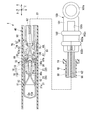
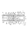
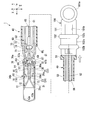
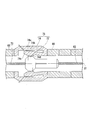
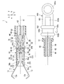
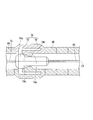
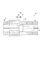
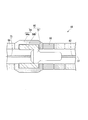
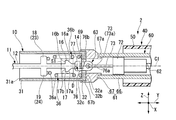
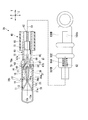
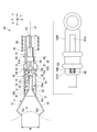
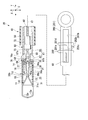
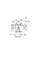
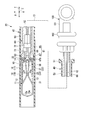
- FIG. 1B is a partial cross-sectional plan view schematically showing the distal end side of the endoscope clip in FIG. 1A. It is an expanded sectional view showing composition of a control part of an endoscope clip concerning this embodiment. It is a fragmentary sectional view showing the initial state of the endoscope clip concerning this embodiment typically. It is a fragmentary sectional view showing operation which opens an arm member of an endoscope clip concerning this embodiment. It is an expanded sectional view which shows the state of the control part of the endoscope clip in FIG.
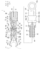
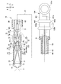
- FIG. 1 It is a fragmentary sectional view showing the state where regulation by a regulation part of an endoscope clip concerning this embodiment was canceled. It is an expanded sectional view which shows the state of the control part of the endoscope clip in FIG. It is a fragmentary sectional view showing the state where the control part of the endoscope clip concerning this embodiment was moved to the tip. It is an expanded sectional view which shows the state of the control part of the endoscope clip in FIG. It is a fragmentary sectional view showing the state where the endoscope clip concerning this embodiment grasps a target tissue. It is a side view partial sectional view showing the state where the arm member of the endoscope clip concerning this embodiment was locked. FIG.
- FIG. 11B is a partial cross-sectional plan view schematically showing the distal end side of the endoscope clip in FIG. 11A.
- FIG. 6 is a partial cross-sectional view showing an operation of placing the clip unit of the endoscope clip according to the present embodiment inside the body. It is an expanded sectional view showing composition of a control part concerning one modification of this embodiment.
- FIG. 14 is an enlarged cross-sectional view showing an operation of releasing the restriction by the restriction portion of the endoscope clip according to the present modification. It is a perspective view showing composition of an engaged member of a control part concerning this modification. It is a side view partial sectional view showing typically composition of an endoscope clip concerning a 2nd embodiment of the present invention.
- FIG. 6 is a partial cross-sectional view showing an operation of placing the clip unit of the endoscope clip according to the present embodiment inside the body. It is an expanded sectional view showing composition of a control part concerning one modification of this embodiment.
- FIG. 14 is an enlarged cross-sectional view showing
- FIG. 16B is a partial cross-sectional plan view schematically showing the distal end side of the endoscope clip in FIG. 16A.
- FIG. 16B is a cross-sectional view in the radial direction of the operation portion of the endoscope clip in FIG. 16A. It is a fragmentary sectional view showing the state where regulation by a regulation part of an endoscope clip concerning this embodiment was canceled.
- FIG. 17B is a partial cross-sectional plan view schematically showing the distal end side of the endoscope clip in FIG. 17A. It is a side view partial sectional view showing typically composition of an endoscope clip concerning the 1st modification of this embodiment.
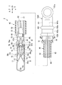
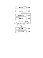
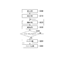
- FIG. 19B is a cross-sectional plan view of the restriction portion in the operation portion of the endoscope clip in FIG. 19A. It is a side view partial sectional view showing the state where regulation by the regulation part of the endoscope clip concerning this modification opened. It is a flow chart which shows a technique by an endoscope clip concerning this embodiment. It is a partial cross section figure which shows the structure of the endoscope treatment tool of a prior art. It is a flowchart which shows the operation
- the endoscope clip 1 according to the present embodiment is used by being inserted into a patient's body through a channel formed in an endoscope (not shown).
- the side on which the endoscope operation section for the operator to operate the endoscope is located is defined as the proximal side
- the side on which the tip section of the endoscope inserted into the body is located is the tip. Define as side.
- the endoscope clip 1 includes a clip unit (hereinafter, abbreviated as “clip”) 10 and a treatment tool body (applicator) 40. .
- the clip 10 is detachably connected to the distal end portion of the treatment instrument body 40.
- FIG. 1A is a side view partial cross-sectional view of the clip 10 along a plane passing through an axis C1 of a pressing tube 31 described later.
- the axis C1 is regarded as the axis of the clip 10 and the insertion portion 60 described later.
- FIG. 1A is a side view partial cross-sectional view of the clip 10 along a plane passing through an axis C1 of a pressing tube 31 described later.
- the axis C1 is regarded as the axis of the clip 10 and the insertion portion 60 described later.
- FIG. 1A is a side view partial cross-sectional view of the clip 10 along a plane passing through an axis C1 of a pressing tube 31 described later.
- An orthogonal direction Z that is orthogonal to each of the direction X and the axial direction Y is defined.
- the clip 10 is configured to include an arm member 11, a pressing tube 31, and an elastic member (a spiral spring) 36.
- the presser pipe 31 is formed in a cylindrical shape and has an inner diameter into which the base end portion of the arm member 11 can enter. That is, the pressing tube 31 is formed with a lumen into which the arm member 11 having the first arm 12 and the second arm 13 described later can enter.
- the elastic member 36 is arranged in the lumen of the pressing tube 31.
- the arm member 11 has a first arm 12, a second arm 13, and a central portion 14.
- the first arm 12 and the second arm 13 extend from the base end side toward the tip end side and are arranged to face each other.
- the central portion 14 is located between the base end portion of the first arm 12 and the base end portion of the second arm 13.
- the first arm 12 and the second arm 13 may be formed at positions symmetrical with respect to the axis C1.
- the “natural state” means a state in which an external force does not act on the arm member 11.
- the state in which the force by the inner wall of the pressing tube 31 does not act on the first arm 12 and the second arm 13 of the arm member 11 is a natural state.
- a claw 12a extending toward the second arm 13 side is formed at the tip of the first arm 12.
- a claw 13a extending toward the first arm 12 side is formed at the tip of the second arm 13.
- the first arm 12 and the second arm 13 are formed to have a rounded shape in a cross-sectional shape orthogonal to the longitudinal direction on the tip side, which is an arc shape. More specifically, the central portions of the outer surfaces of the first arm 12 and the second arm 13 in the orthogonal direction Z, which will be described later, are formed into a curved surface that is convex toward the outside. With such a configuration, the first arm 12 and the second arm 13 have improved strength against bending, reduce frictional resistance to the outer sheath 50 described later, and can move back and forth smoothly.
- first locked portions 16 and 17 are provided at the base end portion of the first arm 12.
- the first locked portions 16 and 17 are provided on the reference plane S1 parallel to the axis line (central axis line) C1 of the pressing tube 31 so as to project from the side surface of the first arm 12 in the orthogonal direction Z.
- the first locked portions 16 and 17 may project in directions opposite to each other and may be formed at positions symmetrical with respect to the axis C1.
- FIG. 1B is a plan view partial cross-sectional view of the clip 10 seen in a direction orthogonal to the reference plane S1.
- the base end surface 16a of the first locked portion 16 is inclined away from the first arm 12 (center axis C1) toward the distal end side.
- the tip end surface 16b of the first locked portion 16 is orthogonal to the axial direction Y.
- the base end surface 17a of the first locked portion 17 and the base end surface 16a of the first locked portion 16 are line-symmetric with respect to the axis C1.
- the tip surface 17b of the first locked portion 17 and the tip surface 16b of the first locked portion 16 may be line-symmetric with respect to the axis C1.
- two protrusions 18 and 19 are provided on the front end side of the first engaged portions 16 and 17 of the first arm 12.
- the protrusions 18 and 19 protrude from the side surface of the first arm 12 in the orthogonal direction Z.
- the protrusion 18 and the protrusion 19 may be line-symmetric with respect to the axis C1 in a plan view.
- the length of the protrusions 18 and 19 protruding from the first arm 12 may be longer than the length of the first locked portions 16 and 17 protruding from the first arm 12 in the orthogonal direction Z.
- the second arm 13 has second locked portions 21, 22 formed in the same manner as the first locked portions 16, 17 and the protrusions 18, 19 of the first arm 12.
- Protrusions 23 and 24 are provided (the second locked portion 22 and the second protrusion 24 are not shown). That is, the second locked portions 21 and 22 of the second arm 13 project from the side surface of the second arm 13 in the orthogonal direction Z which is a direction in which the second arm 13 is separated from the first arm 12.
- the projections 23 and 24 of the second arm 13 project in the orthogonal direction Z from the side surface of the second arm 13 to the tip side of the second locked portions 21 and 22 of the second arm 13.
- the second locked portions 21 and 22, the projections 23 and 24, and the first locked portions 16 and 17 and the projections 18 and 19 are arranged side by side in the facing direction X, respectively.
- the second locked portions 21 and 22 overlap the first locked portions 16 and 17, respectively, and the protrusions 23 and 24 overlap the protrusions 18 and 19, respectively.
- the arm member 11 is made of a material such as a cobalt chrome alloy, titanium, or stainless steel.
- the clip 10 is also configured so that it can be observed under MRI (Nuclear Magnetic Resonance Imaging) fluoroscopy.
- the arm member 11 is made of, for example, a plate material formed of a cobalt chrome alloy, a first arm 12, a second arm 13, a central portion 14, first engaged portions 16, 17, a second engaged portion 21, 22 and the protrusions 18, 19, 23, and 24 are punched into a flat shape.
- the arm member 11 is bent at the connecting portion between the first arm 12 and the central portion 14 and the connecting portion between the second arm 13 and the central portion 14 to form a C-shape in a side view, It is integrally formed.
- the first arm 12 and the second arm 13 of the arm member 11 have an elastic restoring force that moves in a direction in which their respective tips are separated from each other, that is, a direction in which the arm member 11 opens.
- a locking portion 32 is formed on the inner wall of the base end portion of the pressing tube 31 so as to project over the entire circumference.
- the edge portion 32a of the locking portion 32 on the axis C1 side is formed in a circular shape coaxial with the pressing tube 31.
- the base end surface 32b (base end side end surface) and the tip end surface 32c (tip end side end surface) of the locking portion 32 are orthogonal to the axial direction Y.
- a portion of the first arm 12 closer to the base end than the protrusions 18 and 19, a portion of the second arm 13 closer to the base end than the protrusions 23 and 24, and the central portion 14 are inserted into the locking portion 32. It is possible. As will be described later, when the operator pulls back the slider 102 to the base end side, the first arm 12 and the second arm 13 move to the base end side together with the operation wire 62, and the first arm 12 and the second arm 13 move. The proximal portion passes through the locking portion 32 and is locked at a position closer to the proximal end than the locking portion 32.
- a tapered surface 31a is formed on the inner wall of the tip portion of the pressing tube 31 over the entire circumference.
- the tapered surface 31a has a diameter that increases toward the tip side.
- the pressing tube 31 and the locking portion 32 may be integrally formed of a material such as 64 titanium alloy (Ti-6AL-4V) or cobalt chrome alloy.
- an end turn portion 36b is provided at the tip of the elastic member 36.
- the end turn portion 36b is formed to have an inner diameter smaller than that of the other portion of the elastic member 36.
- the elastic member 36 is accommodated in the presser pipe 31 and has a distal end locked to the projections 18, 19, 23, 24 and a proximal end locked to the locking part 32.
- the base end portion of the elastic member 36 and the locking portion 32 may be fixed by welding or the like.
- the elastic member 36 a portion of the first arm 12 closer to the base end than the protrusions 18 and 19, a portion of the second arm 13 closer to the base end than the protrusions 23 and 24, and the central portion 14 can be inserted. Is.
- the protrusions 18, 19, 23, 24 move to the base end side
- the protrusions 18, 19, 23, 24 are locked by the end turn portion 36b of the elastic member 36.
- the elastic member 36 is compressed by the protrusions 18, 19, 23, 24 in the axial direction Y.
- the elastic member 36 is compressed, an elastic force that pushes the arm member 11 out of the holding tube 31 in the axial direction Y is generated. Even when the elastic member 36 does not include the end turn portion 36b, the same effect can be obtained by attaching another member such as a washer to the tip of the elastic member 36.
- the treatment instrument body 40 includes an outer sheath 50, an insertion portion 60, and an operation portion 100.
- the outer sheath 50 can be formed of, for example, a fluororesin such as PTFE (polytetrafluoroethylene) or a resin material such as HDPE (high density polyethylene).
- An outer sheath operating section 51 for operating the outer sheath 50 is provided on the proximal end side of the outer sheath 50.
- the outer sheath 50 can be pulled back to the insertion portion 60 of the treatment instrument body 40.
- the insertion portion 60 can move back and forth within the outer sheath 50.
- the operation unit 100 is attached to the base end of the insertion unit 60.
- the insertion portion 60 of the treatment instrument body 40 includes a sheath portion 61, an operation wire (wire) 62, a connecting member 63, and a loop portion 73.
- the operation wire 62 is inserted into the sheath portion 61 so as to be able to move forward and backward.
- the operation wire 62 is provided for transmitting to the clip 10 the amount of force with which the operator operates the operation section 100 on the proximal end side (for example, the operation of pushing in the slider 102 and the operation of pulling back the slider 102).
- the connecting member 63 is connected to the distal end portion of the operation wire 62.
- the connecting member 63 is provided rotatably around an axis parallel to the facing direction X with respect to the operation wire 62.
- the sheath portion 61 includes a coil sheath 66, a tip member (stopper engaging portion) 67 fixed to the tip portion of the coil sheath 66, and a fixing member (engaged portion) 74 provided on the inner peripheral surface of the coil sheath 66.
- the coil sheath 66 may be formed of stainless steel such as SUS301 having high compressive strength.
- As the coil sheath 66 it is possible to use a coil formed by closely winding an unillustrated wire in the axial direction Y.
- the coil sheath 66 has flexibility and is strong against a compressive force in the axial direction Y.
- the inner diameter of the coil sheath 66 may be substantially equal to the inner diameter of the elastic member 36.
- the tip member 67 may be formed in a cylindrical shape from, for example, stainless steel.
- the inner diameter of the tip member 67 is smaller than the inner diameter of the coil sheath 66.
- the outer diameter of the tip member 67 is larger than the outer diameters of the coil sheath 66 and the pressing tube 31.
- a concave portion 67a is formed on the outer peripheral surface of the base end portion of the tip member 67 by reducing the outer diameter.
- the inner diameter of the distal end member 67 on the distal end side of the coil sheath 66 with respect to the coil sheath 66 is reduced, so that the connecting portion between the coil sheath 66 and the distal end member 67 is stepped.
- the portion 68 is formed.
- the inner diameter of the tip member 67 allows the tip member 67 to engage with the first locked portions 16 and 17 and the second locked portions 21 and 22 when the clip 10 described later is locked to the locking portion 32. It may be as large as there is not.
- a step is formed on the inner peripheral surface of the tip portion of the tip member 67 over the entire circumference.
- the front facing surface is the front end supporting surface (front end surface) 67b.
- a support portion 69 is formed on the tip side of the tip support surface 67b.
- the support portion 69 is formed in a cylindrical shape.
- the inner diameter of the support portion 69 is slightly larger than the outer diameter of the pressing tube 31, and can receive the base end of the pressing tube 31.
- the tip support surface 67b can contact the base end surface of the pressing tube 31.
- the clip 10 is arranged on the distal end side of the sheath portion 61.
- the support portion 69 can support the outer peripheral surface of the pressing tube 31 that is in contact with the tip support surface 67b.
- the wobbling of the clip 10 with respect to the support portion 69 can be suppressed as small as possible, and a certain degree of inclination of the clip 10 with respect to the support portion 69 can be allowed. Therefore, the endoscope clip 1 can be smoothly inserted even in a bent shape such as a channel of the endoscope.
- the fixing member (engaged portion of the restriction portion) 74 is provided on the inner peripheral surface of the distal end side of the sheath portion 61 so as to project toward the axis C1.
- the fixing member 74 may be fixed by welding the tip end and the base end along the axial direction Y to the wire forming the coil sheath 66. That is, the fixing member 74 may be formed integrally with the coil sheath 66.
- the fixing member 74 is not limited to this configuration.
- the fixing member 74 may be fixed to the inner peripheral surface on the distal end side of the coil sheath 66 formed by tightly winding the wire in the axial direction Y by welding or bonding.
- the fixing member 74 is not limited to the example in which the fixing member 74 is sandwiched between the wires forming the coil sheath 66, as shown in FIG. 2.
- the fixing member 74 is arranged on the tip side of the coil-sheath 66, and the base end of the fixing member 74 along the axial direction Y is fixed to the wire forming the coil sheath 66 by a method such as welding or adhesion. Good.
- the material forming the fixing member 74 is not particularly limited.
- the fixing member 74 may be formed of the same metal material as the pressing tube 31 and the locking portion 32.
- the fixing member 74 As shown in FIG. 2, which is a cross-sectional view of the fixing member 74, the fixing member 74 according to the present embodiment is configured to have a supporting portion 74a and a deforming portion 74b.
- the support portion 74a is formed radially outward of the deformable portion 74b with respect to the axis C1.
- a wire forming the coil sheath 66 is fixed to the distal end and the proximal end of the support portion 74a.
- the deformable portion 74b has a base end portion connected to the base end portion of the support portion 74a, and a portion located closer to the tip end side than the base end portion is formed with a certain distance from the support portion 74a.
- the deformable portion 74b forms a gap with the support portion 74a at a certain distance on the outer side in the radial direction with respect to the axis C1.
- the outer diameter of the fixing member 74 is defined by the maximum width of the support portion 74a in the radial direction orthogonal to the central axis C1.
- the outer diameter of the fixing member 74 may be slightly larger than the outer diameter of the coil sheath 66, for example.
- the deformable portion 74b of the fixing member 74 is formed so that at least a part thereof projects toward the axis C1.
- at least a part of the deformable portion 74b of the fixed member 74 is formed so as to project inward in the radial direction around the axis C1.
- the deforming portion 74b is composed of a pair of claws that are arranged at positions facing each other with the axis C1 interposed therebetween. The distance between the pair of claws (that is, the width of the space between the pair of claws) is smaller than the inner diameter of the coil sheath 66 and the outer diameter of the stopper portion 72 described later.
- the fixing member 74 has an inner diameter smaller than the inner diameter of the coil sheath 66 and the outer diameter of the stopper portion 72 described later.
- the deforming portion 74b may be configured by a single tab.
- the width of the lumen of the fixing member 74 (the lumen having a width smaller than the inner diameter of the coil sheath 66 and the outer diameter of the stopper portion 72 described later) is defined by a single tab.
- the tip end 74c and the base end 74d are formed in an inclined surface in order to engage with a stopper portion 72 described later.
- the deformable portion 74b of the fixing member 74 has a deformable portion 74b when the operator pushes the slider 102 of the operating portion 100 while the fixing member 74 and a stopper portion 72 described later are in contact (engagement). By being pushed into the stopper portion 72, it can be elastically deformed by rotating radially outward with the connecting portion between the supporting portion 74a and the deforming portion 74b as a fulcrum.
- the operation wire 62 is formed of, for example, a metal single wire or a twisted wire.
- the distal end of the operation wire 62 is connected to the proximal end of the stopper portion 72. That is, in the present embodiment, both the operation wire 62 and the stopper portion 72 can move.
- the loop portion 73 is connected to the tip portion of the stopper portion 72.
- the stopper portion (engagement portion) 72 is formed of, for example, metal in a cylindrical shape.
- the outer diameter of the stopper portion 72 is smaller than the inner diameter of the coil sheath 66 and larger than the inner diameter of the tip member 67. Further, as described above, the outer diameter of the stopper portion 72 is larger than the width of the inner cavity formed inside the fixing member 74.
- the stopper portion 72 has a tapered distal end surface and a proximal end surface at the distal end and the proximal end along the axial direction Y.
- the tip end is generated by the elastic force of the elastic member 36 provided in the pressing tube 31 in a state where the amount of operation force by the operator does not act. It can be biased to the side and engage the fixing member 74. Further, when the operator pushes the slider 102 of the operation section 100, the stopper section 72 moves to the tip side and can get over the fixing member 74. Further, when the operator pushes the slider 102 of the operation section 100, the stopper section 72 comes into contact with the step section 68 of the tip member 67, so that the arm member 11 of the clip 10 is moved to the first arm 12 and the second arm 13. And can be transitioned to an open configuration in which they are spaced apart from each other.
- the loop portion 73 is formed by folding back one wire 73a.
- the wire 73a has a folded-back portion located on the tip end side, and both ends on the base end side are fixed to the stopper portion 72 by brazing, resistance welding, or the like.
- the connecting member 63 has a hook portion 77 at the tip of the connecting portion main body 76 and a through hole 76 a formed at the base end of the connecting portion main body 76.
- An inclined surface 76b is formed on a surface of the connecting portion main body 76 facing the hook portion 77.
- the connecting member 63 is rotatable about an axis parallel to the facing direction X with respect to the loop portion 73 by inserting the folded portion of the wire 73a of the loop portion 73 into the through hole 76a (direction of arrow D in FIG. 1B). Is rotatable).
- the width of the connecting member 63 is the outer diameter in the direction orthogonal to the central axis C1 of the connecting portion main body 76 when the hook portion 77 is arranged on the tip side.
- the width of the connecting member 63 is slightly smaller than the inner diameter of the elastic member 36, the inner diameter of the coil sheath 66, and the inner diameter of the tip member 67. That is, the connecting member 63 cannot rotate with respect to the loop portion 73 in the pressing tube 31 and the sheath portion 61 from the state where the hook portion 77 is on the distal end side. In other words, the pressing tube 31 and the sheath 61 restrict the relative movement of the arm member 11 and the hook 77 in the radial direction.
- the connecting member 63 cannot rotate with respect to the loop portion 73 means that the connecting member 63 rotates with respect to the loop portion 73 until the engagement between the hook portion 77 and the central portion 14 is released. Means you can't. Therefore, "the connecting member 63 cannot rotate with respect to the loop portion 73" does not mean that the connecting member 63 cannot literally rotate with respect to the loop portion 73.
- the hook portion 77 By disposing the central portion 14 between the hook portion 77 of the connecting member 63 and the inclined surface 76b, the hook portion 77 can be engaged with the central portion 14.
- the hook portion 77 rotates in the direction D with respect to the loop portion 73, the engagement between the hook portion 77 and the central portion 14 is released (see FIG. 10). That is, the connecting member 63 is detachably connected to the arm member 11.
- the connecting member 63 is located inside the presser pipe 31.
- the configuration including both the stopper portion 72 and the fixing member 74 is defined as the regulation portion 75 of the endoscope clip 1
- the stopper portion 72 is defined as the engagement portion of the regulation portion 75
- the fixing member 74 is defined as the engaged portion of the restriction portion 75.
- the elastic member 36 provided in the pressing tube 31 is in a state in which the stopper portion 72 is located closer to the base end side than the fixing member 74 and the operator does not hold the slider 102.
- the elastic force causes the stopper portion 72 to move toward the distal end side along the axial direction Y and abut (engage) with the fixing member 74.
- the stopper portion 72 and the fixing member 74 are engaged with each other, so that both the elastic force of the elastic member 36 acting on the stopper portion 72 and the fixing force of the fixing member 74 are balanced.
- the fixing force by the fixing member 74 means the amount of force that prevents the stopper member 72 and the fixing member 74 from engaging with each other and pushing them against each other to prevent (restrict) the movement of the stopper member 72 toward the distal end side by the fixing member 74. is doing.
- the stopper portion 72 when the elastic force of the elastic member 36 acts on the stopper portion 72, the stopper portion 72 is urged toward the tip side, and when the stopper portion 72 abuts on the fixing member 74, a force amount that pushes the fixing member 74 toward the tip side is generated. To do.
- the fixing member 74 receives this force, the deforming portion 74b elastically deforms outward in the radial direction with respect to the axis C1, the inner diameter of the lumen increases, and a repulsive force (fixing force) that opposes the elastic force of the elastic member 36 (fixing). Force) is generated.
- the fixing force generated when the inner diameter of the fixing member 74 becomes equal to the outer diameter of the stopper portion 72 is set to be equal to or larger than the elastic force of the elastic member 36. Therefore, in a state where the operator does not operate the slider 102, that is, a state where an external force does not act on the operation wire 62, the stopper portion 72 does not move over the fixing member 74 along the axial direction Y and move to the tip side. . In other words, the engagement between the stopper portion 72 and the fixing member 74 is maintained and the movement of the operation wire 62 toward the distal end side is restricted in a state where the amount of operation force by the operator does not act on the slider 102.
- the restriction portion 75 is provided to restrict the movement of the operation wire 62 of the endoscope clip 1 toward the distal end side in a natural state in which no external force acts. Further, as will be described later, the restricting portion 75 is provided for restricting the transition of the arm member 11 of the clip 10 from the closed form to the open form in a natural state where no external force acts.
- the closed form of the arm member 11 may be set such that the first arm 12 and the second arm 13 are in contact with each other or the distance between the tip of the first arm 12 and the tip of the second arm 13 is It is defined as a state that is almost zero.
- the claw 12a of the first arm 12 and the claw 13a of the second arm 13 are not directed forward. This means that the first arm 12 and the second arm 13 are separated from each other to some extent.
- the restriction by the restriction portion 75 is released, The operation wire 62 can move to the tip side.
- the fixing member 74 of the restricting portion 75 is arranged closer to the base end side than the elastic member 36 provided inside the pressing tube 31. More preferably, the fixing member 74 of the restricting portion 75 is arranged at a position closer to the proximal end side than the distal end opening of the sheath portion 61.
- the fixing member 74 of the restricting portion 75 may be arranged at a position within about 1 cm from the distal end opening of the sheath portion 61 toward the proximal end side.
- the stopper portion 72 of the restriction portion 75 can move to the tip end side until it comes into contact with the step portion 68 formed on the base end side of the tip end member 67.
- the distance between the position where the stopper portion 72 engages with the fixing member 74 and the position of the arm member 11 becomes small.
- the stopper portion 72 and the arm member 11 are formed. It is possible to suppress a change in the path length between and. As a result, the arm member 11 can be more reliably maintained in the closed configuration by the engagement of the fixing member 74 and the stopper portion 72.
- the operation unit 100 has an operation unit body (handle) 101 and a slider 102.
- the operation section body 101 is attached to the proximal end of the coil sheath 66.
- the operation portion main body 101 is formed in a rod shape extending in the axial direction Y, and has a finger hook portion 101a at the base end portion.
- the operation unit main body 101 is provided with a slit 101b extending in the axial direction Y.
- the slider 102 is provided so as to be inserted into the operation unit body 101.
- the slider 102 is slidable (moves forward and backward) in the axial direction Y with respect to the operation unit main body 101.
- the proximal end of the operation wire 62 is connected to the slider 102.
- the operation wire 62 is moved forward or backward by moving the slider 102 forward or backward in the axial direction Y.
- the diameter expansion member 72, the loop portion 73, and the arm member 11 of the clip 10 provided on the distal end side of the operation wire 62 can be moved forward or backward.
- the pair of first arm 12 and second arm 13 of the arm member 11 can be opened or closed.
- the slider 102 is formed in a cylindrical shape. On the outer peripheral surface of the slider 102, a recess 102a is formed over the entire circumference. On the slider 102, a flange portion 102b, a recess 102a, and a flange portion 102c are formed in this order from the front end side to the base end side in the axial direction Y.
- the pair of collars 102b and 102c have an elliptical shape when viewed in the axial direction Y. As a result, the slider 102 can be easily gripped, and space can be saved when the operation unit 100 of the endoscope clip 1 is packed.
- the slider 102 engages with the slit 101b of the operation portion main body 101 to limit the movement range of the slider 102 with respect to the operation portion main body 101 in the axial direction Y.
- the elastic member 36 of the clip 10 in the initial state, has a structure in which the strands 36a adjacent to each other in the axial direction Y are separated from each other and is in a natural state (a state in which no external force acts). Is also slightly compressed in the axial direction Y. Therefore, due to the elastic force of the elastic member 36, the pressing tube 31 is held by the distal end member 67 in a state where the proximal end surface is in contact with the distal end supporting surface 67b of the distal end member 67.
- the elastic force of the elastic member 36 loads the arm member 11 of the clip 10, so that the elastic force of the elastic member 36 has a function of pushing the arm member 11 out of the holding pipe 31. is there. That is, when the elastic force of the elastic member 36 is applied to the arm member 11, the stopper portion 72 is moved to the tip side. As a result, the stopper portion 72 and the fixing member 74 come into contact with each other and press each other.
- the stopper portion 72 is located closer to the proximal end side than the fixing member 74 in the sheath portion 61. Therefore, the elastic force of the elastic member 36 urges the stopper portion 72 toward the distal end side along the axial direction Y and moves to the distal end side until it comes into contact with the fixing member 74.
- the stopper portion 72 abuts (engages) with the fixing member 74, the elastic force of the elastic member 36 and the fixing force generated by the elastic deformation of the fixing member 74 oppose and balance each other, so that the stopper portion 72 is fixed. The state in which the member 74 and the member 74 are engaged with each other is maintained.
- the deforming portion 74b of the fixing member 74 is pressed by the stopper portion 72. In this state, the slider 102 of the operation portion 100 on the base end side is separated from the tip end surface and the base end surface of the slit 101b of the operation portion main body 101 with a certain distance.
- the base end portion of the first arm 12, the base end portion of the second arm 13, and the central portion 14 are located on the tip side of the locking portion 32 in the holding tube 31. Good.
- the stopper portion 72 abuts the fixing member 74, the first locked portions 16 and 17 and the second locked portions 21 and 22 of the arm member 11 are located on the tip side of the locking portion 32.
- the first locked portions 16 and 17 and the second locked portions 21 and 22 are not in contact with the locking portion 32 of the pressing tube 31.
- the first arm 12 and the second arm 13 of the arm member 11 are in contact with a tapered surface 31a formed in a part between the tip and the base end thereof over the entire circumference of the inner wall of the tip portion of the pressing tube 31.
- the first arm 12 and the second arm 13 of the arm member 11 are spaced apart from the inner wall of the outer sheath 50 with a space therebetween.
- the tip of the first arm 12 and the tip of the second arm 13 are in contact with each other, or the distance between the tip of the first arm 12 and the tip of the second arm 13 is substantially zero. become.
- this state is the closed form of the clip 10.
- the operator can adjust the orientation of the clip 10 by rotating the operation wire 62 with respect to the sheath portion 61 and rotating the arm member 11 around the axis C1 with respect to the pressing tube 31. .
- the edge portion 32a of the locking portion 32 is formed in a circular shape coaxial with the pressing tube 31, even when the arm member 11 is rotated around the axis C1, the locking portion 32 and the first portion 32a. The locking by the first locked portions 16 and 17 and the second locked portions 21 and 22 is kept good.
- the operator When using the endoscope clip 1, the operator inserts an endoscope (not shown) into the patient's body. Then, the operator inserts the endoscope clip 1 from the proximal end portion of the channel of the endoscope, and projects the outer sheath 50 of the endoscope clip 1 from the distal end portion of the channel of the endoscope.
- the fixing force generated when the width of the inner cavity of the fixing member 74 becomes equal to the outer diameter of the stopper portion 72 is equal to or larger than the elastic force of the elastic member 36. It is set. Therefore, even when the first arm 12 and the second arm 13 of the arm member 11 are projected from the distal end portion of the channel of the endoscope, the state where the stopper portion 72 and the fixing member 74 are engaged is maintained. Has been done. That is, the fixing member 74 of the restriction portion 75 and the stopper portion 72 are engaged with each other, and the movement of the operation wire 62 toward the distal end side is restricted.
- the sum of the amount of operation force of the operator and the elastic force of the elastic member 36 can be provided by the maximum value of the fixing force of the fixing member 74 of the restriction portion 75, that is, the engagement of the stopper portion 72 and the fixing member 74. It becomes more than the maximum value of the regulation power.
- the stopper portion 72 is pushed into the inner cavity of the fixing member 74 by the pushing of the slider 102 by the operator while contacting the deformed portion 74b of the elastically deformed fixing member 74.
- the operator pushes the slider 102 to move the operation wire 62 and the stopper portion 72 to the fixing member 74. Can be moved to the tip side.
- the connecting portion 63 and the arm member 11 connected to the distal end side of the operation wire 62 are moved to the distal end side together with the operation wire 62.
- the first arm 12 and the second arm 13 of the arm member 11 are in contact with the tapered surface 31a formed at the tip of the pressing tube 31 while their tips are separated from each other.
- the first arm 12 and the second arm 13 of the arm member 11 are separated from each other so that the distance between their tips becomes large. That is, the operator can transition the arm member 11 from the closed configuration to the open configuration by pushing in the slider 102.
- the distance between the first arm 12 and the second arm 13 of the arm member 11 is smaller than the maximum opening width possible.
- the elastic force of the elastic member 36 and the regulating force of the regulating portion 75 are in balance, the sum of the amount of operating force by which the operator pushes the slider 102 and the elastic force of the elastic member 36 is equal to that of the regulating portion 75.
- the regulation by the regulation unit 75 can be released. That is, in the present embodiment, the amount of operation force by the operator does not need to exceed the elastic force of the elastic member 36, and the amount of operation force can be easily controlled.
- the operator pushes the slider 102 in the process in which the stopper portion 72 contacts the fixing member 74 and moves toward the tip side with respect to the fixing member 74 when the slider 102 is pushed by the operator. It is also possible to pull it once to the base end side. Accordingly, the stopper portion 72 can move to the base end side with respect to the fixing member 74 while contacting the fixing member 74. That is, the first arm 12 and the second arm 13 of the arm member 11 can be transitioned from the open configuration to the closed configuration by retracting the slider 102 by the operator.
- the opening width of the arm member 11 when the opening width of the arm member 11 is adjusted according to the target tissue T to be treated, even if the arm member 11 is opened too much, the opening width of the arm member 11 can be readjusted again. it can.
- the arm member 11 is moved in the body in order to place the clip 10 at a different position to be treated, the body walls of the open first arm 12 and the second arm 13 in the arm member 11 are removed. It is easy to handle the treatment tool while preventing unintended contact with the.
- the operation wire 62, the connecting portion 63, and the arm member 11 are moved to the distal end side, and the first arm 12 and the arm member 11 of the arm member 11 are moved.
- the opening width of the second arm 13 increases.
- the stopper portion 72 rides over the deformed portion 74b of the fixed member 74 and is positioned on the tip side of the deformed portion 74b of the fixed member 74. At this time, the engagement between the stopper portion 72 and the fixed member 74 is released, and the deformed portion 74b of the fixed member 74 is restored to the initial shape.
- the stopper portion 72 of the restricting portion 75 and the fixing member 74 are engaged with each other, and a force larger than the fixing force generated by elastically deforming the fixing member 74 is applied to the operation wire 62, whereby the operation wire 62 is loaded.
- the restriction on the movement of 62 toward the tip side is released.
- the first locked portions 16 and 17 and the second locked portions 21 and 22 of the arm member 11 are located in the holding pipe 31 on the tip side of the locking portion 32. .
- the operation wire 62 can be advanced until the stopper portion 72 contacts the step portion 68 of the tip member 67.
- the arm member 11 advances together with the operation wire 62. Therefore, the first arm 12 and the second arm 13 of the arm member 11 can further increase the opening width between the first arm 12 and the second arm 13 while contacting the tapered surface 31a of the tip portion of the pressing tube 31.
- the opening width of the arm member 11 continues to increase as the operation wire 62 advances in the present embodiment will be described.
- the opening width of the arm member 11 becomes the maximum value W1.
- the stopper 72 abuts the step 68 of the tip member 67 and cannot move further toward the tip side, so that the opening width of the arm member 11 is maximum.
- the state where the value is W1 can be maintained.
- the present invention is not limited to this.
- the opening width of the arm member 11 reaches the maximum value W1 before the stopper portion 72 abuts on the step portion 68 in the process in which the arm member 11 advances together with the operation wire 62. It can be reached.
- the first arm 12 and the second arm 13 of the arm member 11 can be preferably opened.
- the operator can operate the endoscope (not shown) to adjust the orientation and posture of the arm member 11 of the clip 10 and press the arm member 11 toward the target tissue T.
- the operator pulls the slider 102 back toward the proximal end side, so that the stopper portion 72 comes into contact with the fixing member 74 again. It is possible to move. At this time, the movement of the operation wire 62 toward the distal end side is regulated by the regulation portion 75, and the arm member 11 is changed from the open configuration to the closed configuration.
- the operator can position the target tissue T between the first arm 12 and the second arm 13 of the open-state arm member 11 having the maximum width W1.
- the operator confirms that the target tissue T is located between the first arm 12 and the second arm 13, the operator operates the endoscope to push the arm member 11 toward the target tissue T, thereby T can be held.
- the operator grips the operation section main body 101 and pulls back the slider 102.
- the first arm 12 and the second arm 13 are moved to the base end side together with the operation wire 62.
- the first arm 12 and the second arm 13 come into contact with the tapered surface 31a (inner peripheral surface) of the tip portion of the pressing tube 31, and the first arm 12 elastically deforms toward the second arm 13 side.
- the second arm 13 elastically deforms toward the first arm 12 side.
- the tip end of the first arm 12 and the tip end of the second arm 13 approach each other, and the opening width of the arm member 11 decreases.
- the arm member 11 transitions from the open form to the closed form.
- the target tissue T is held by the first arm 12 and the second arm 13.
- the arm member 11 is closed. It is also included in the form. At this time, the elastic member 36 is compressed in the axial direction Y.
- the stopper portion 72 can again contact (engage) with the fixing member 74.
- the stopper portion 72 since the stopper portion 72 has the tapered base end surface, it can easily get over the fixing member 74 while moving to the base end side.
- the stopper portion 72 gets over the fixing member 74 and is positioned closer to the base end side than the fixing member 74.
- the stopper portion 72 and the fixing member 74 are in a state of abutting (engaging) each other. That is, in a natural state in which no external force acts, the regulation portion 75 can regulate the movement of the operation wire 62 toward the distal end side by the engagement of the stopper portion 72 and the fixing member 74.
- the root of the target tissue T is tightly bound by the first arm 12 and the second arm 13 of the arm member 11 in the closed state.
- the engagement of the stopper portion 72 and the fixing member 74 restricts the transition of the arm member 11 from the closed state to the open state. Therefore, even if the operator does not hold the slider 102, the target tissue T is maintained in a state of being grasped by the arm member 11 in the closed state.
- both the front end surface 16b of the first locked portion 16 and the front end surface 17b of the first locked portion 17 contact the base end surface 32b of the locking portion 32. In contact with each other, the first locked portion 16 and the first locked portion 17 are locked to the locking portion 32.
- both the front end surface (not shown) of the second locked portion 21 and the front end surface (not shown) of the second locked portion 22 contact the base end surface 32b of the locking portion 32, The locked portion 21 and the second locked portion 22 are locked to the locking portion 32.
- an example of a process in which the first locked portion 16 and the first locked portion 17 are locked by the locking portion 32 will be described.
- the locking portion 32 of the pressing tube 31 is attached to the base end surface 16a of the first locked portion 16 of the arm member 11 and the first engaged member.
- the base end surface 17a of the stopper portion 17, the base end surface (not shown) of the second locked portion 21, and the base end surface (not shown) of the second locked portion 22 are in contact with each other.
- the elastic member 36 is compressed in the axial direction Y by the protrusion 18 and the protrusion 19.
- the connecting member 63 of the treatment instrument main body 40 is arranged in the pressing tube 31 or the sheath portion 61, the connecting member 63 cannot rotate with respect to the loop portion 73, and the hook portion 77 and the central portion 14 are not connected to each other.
- the engagement is retained.
- both the operation wire 62 and the stopper portion 72 are moved to the base end side.
- the engagement state between the stopper portion 72 and the fixing member 74 is released, and the stopper portion 72 is moved to a position separated from the fixing member 74 on the base end side of the fixing member 74.
- the compressed elastic member 36 expands.
- the arm member 11 can move toward the distal end side with respect to the pressing tube 31 in a state where the pressing tube 31 is in contact with the distal end supporting surface 67b of the distal end member 67. That is, in the process in which the slider 102 is pulled back, the operator operates the endoscope so that the clip 10 can be opposed to the target tissue T again. After that, the target tissue T can be grasped by the clip 10 again by the procedure described above.
- the first arm 12 and the second arm 13 of the arm member 11 are moved to the proximal end side together with the operation wire 62. At that time, the first arm 12 and the second arm 13 elastically deform in a direction in which they approach each other and pass through the inside of the locking portion 32.
- the operator moves the slider 102 more than in the process from the initial state to the contact state.
- the rate of increase in the required amount of force per unit amount of movement for pulling back is increased. That is, the operator feels heavy operation of pulling back the slider 102 from the contact state to the overcoming state. This allows the operator to recognize the state where the slider 102 is currently pulled back.
- the connecting member 63 is arranged inside the sheath portion 61, so that the hook portion 77 and the central portion 14 are connected to each other. Engagement is retained.
- the amount of force required for the arm member 11 to change from the contact state to the overcoming state is, for example, about 20 to 50 N (Newton).
- the first locked portions 16, 17 and the second locked portions 21, 22 move to the base end side beyond the locking portion 32, the first locked portions 16, 17, the second locked portion
- the stoppers 21 and 22 may overcome the locking portion 32 by scraping the locking portion 32 or deforming the locking portion 32.
- chamfering processing is performed on the portions of the first locked portions 16 and 17 and the second locked portions 21 and 22 that come into contact with the locking portions 32. It is preferable to apply such as.
- the first locked portions 16 and 17 and the second locked portions 21 and 22 go beyond the locking portion 32 and further toward the base end side.
- Both the configuration of the first arm 12 on the tip side of the first engaged portions 16 and 17 and the configuration of the second arm 13 on the tip side of the second engaged portions 21 and 22 sequentially include the engaging portion 32. Pass through. In this process, the positions of the first arm 12 and the second arm 13 in the facing direction X and the orthogonal direction Z with respect to the pressing tube 31 are maintained. At this time, the first arm 12, the second arm 13, and the central portion 14 are not biased by the locking portion 32.
- the elastic force of the central portion 14 causes the base end side of the first arm 12 and the base end side of the second arm 13 to move in the facing direction X away from each other.
- the tip end surfaces 16b and 17b of the first locked portions 16 and 17 are moved relative to the base end surface 32b of the locking portion 32. To be in contact with each other to be locked.
- the clip 10 is maintained in the closed state in the process of the operator pulling back the slider 102 and moving from the overriding state to the locked state. Since the connecting member 63 is arranged inside the sheath portion 61, the engagement between the hook portion 77 and the central portion 14 is maintained.
- the strand 36a of the elastic member 36 that is compressed in the axial direction Y has a close contact with the strands 36a adjacent to each other in the axial direction Y. It will be rolled.
- the tip end surfaces 16b and 17b of the first locked portions 16 and 17 are locked to the base end surface 32b of the locking portion 32, so that the tip end side of the arm member 11 with respect to the pressing tube 31 is moved. Movement is restricted. That is, the clip 10 maintains the state in which the target tissue T is ligated.
- the stopper portion 72 is located at a position apart from the fixing member 74 on the base end side of the fixing member 74.
- the operation wire 62, the connecting member 63, and the clip 10 can all be moved to the distal end side.
- the operator separates the clip 10 ligating the target tissue T from the treatment instrument body 40. Specifically, when the operator pushes in the slider 102, the operation wire 62, the connecting member 63, and the clip 10 move toward the distal end side with respect to the coil sheath 66. As shown in FIG. 12, when the connecting member 63 projects further toward the tip side than the tip member 67, the arm member 11 and the pressing tube 31 move integrally to the tip side. When the connecting member 63 is located outside the pressing tube 31 by the operator pushing the slider 102, the connecting member 63 can rotate with respect to the loop portion 73.
- the inclined surface 76b of the connecting member 63 comes into contact with the proximal end surface of the central portion 14 of the clip 10 that ligates the target tissue T.
- the hook portion 77 rotates in the direction D together with the connecting portion main body 76 by being guided by the inclined surface 76b, and the engagement between the hook portion 77 and the central portion 14 is released.
- the clip 10 maintains the closed form. As a result, the clip 10 ligating the target tissue T is left in the body.
- the operator pulls back the slider 102 to house the connecting member 63 in the sheath portion 61. After that, the operator pulls out and takes out the endoscope clip 1 from the channel of the endoscope. Finally, the operator takes necessary measures and ends the series of procedures.
- the arm member 11 of the clip 10 according to the present embodiment has a first arm 12 and a second arm 13.
- the arm member 11 has a closed form in which the first arm 12 and the second arm 13 are closed, and an open form in which the first arm 12 and the second arm 13 are spaced apart from each other.
- the stopper portion 72 that moves together with the operation wire 62, and the fixing member 74 in which an inner cavity having a width smaller than the outer diameter of the stopper portion 72 is formed.
- a regulation unit 75 including The restricting portion 75 can restrict the movement of the operating wire 62 toward the distal end side by the stopper portion 72 and the fixing member 74 engaging with each other. Therefore, when the target tissue T in the body is treated, when the stopper 72 is located closer to the base end side than the fixing member 74, the operator does not have to operate the slider 102 of the operation unit 100 on the base end side. The movement of the wire 62 toward the tip side is restricted. Therefore, the transition of the arm member 11 from the closed form to the open form can be restricted.
- the endoscope clip 1 when the target tissue T in the body is treated, the closed form of the arm member 11 is easily maintained, and the inner wall of the channel of the endoscope or the inside of the body. The unintentional contact of the arm member 11 with the tissue can be prevented. Further, since the operator can shorten the operation of adjusting the endoscope clip 1, it is possible to facilitate the handling, save the operation time, and improve the efficiency.
- the endoscope clip 1 when the stopper portion 72 of the regulating portion 75 and the fixing member 74 are engaged with each other, the regulating force of the regulating portion 75 and the elasticity of the holding pipe 31 are provided.
- the elastic force of the member 36 is balanced. Therefore, it is not necessary for the operator to apply an operation force amount equal to or greater than the elastic force of the elastic member 36 in order to release the regulation of the movement of the operation wire 62 toward the distal end side by the regulation unit 75, and the regulation unit 75 can be operated with a slight force amount.
- the regulation by can be lifted.
- the restricting portion 75 is provided in the sheath portion 61 in a region near the distal end side.
- the stopper portion 72 and the arm member 11 are It is possible to suppress the change in the path length between the two. As a result, the arm member 11 can be more reliably maintained in the closed configuration by the engagement of the fixing member 74 and the stopper portion 72.
- the restriction portion 75 has a simple configuration including the stopper portion 72 and the fixing member 74, and the manufacturing thereof is facilitated. Therefore, the endoscope clip 1 can be manufactured at low cost. 1 can be configured.
- the fixing member 74 having the supporting portion 74a and the deforming portion 74b has been described with respect to the structure of the restricting portion 75 of the endoscope clip 1, but the structure of the restricting portion 75 is not limited to this.
- the restricting unit may restrict the movement of the operation wire 62 toward the tip side even when the operator does not hold the slider 102, and the specific configuration is not limited.
- FIG. 13 is an enlarged cross-sectional view showing a part of the configuration of the endoscope clip 1 according to this modification.
- FIG. 14 is an enlarged cross-sectional view showing a state in which the restriction by the restriction portion 85 of the endoscope clip 1 according to this modification is released.
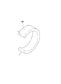
- FIG. 15 is a perspective view showing the structure of the engaged member 84b of the restriction portion 85 according to this modification.
- the endoscope clip 1 according to the present modification is configured to include a regulation portion 85 instead of the regulation portion 75 included in the endoscope clip 1 according to the above-described embodiment.
- the restriction portion 85 of the endoscope clip 1 according to the present modified example is configured to include an engaged portion 84 and a stopper portion (engaging portion) 72.
- the engaged portion 84 of the endoscope clip 1 includes a support member 84a and a C-shaped ring member (deformation portion) 84b.
- the support member 84a is connected to the wire forming the coil sheath 66 at its distal end and proximal end, and is configured integrally with the coil sheath 66.
- the support member 84a may be integrally formed with the coil sheath 66 by a method such as welding.
- the support member 84a is not limited to the example in which the support member 84a is sandwiched between the wires forming the coil sheath 66, as shown in FIG.
- the support member 84a is arranged on the distal side of the coil-sheath 66, and the base end of the support member 84a along the axial direction Y is fixed to the wire forming the coil sheath 66 by a method such as welding or adhesion. Good.
- the support member 84a of the engaged portion 84 may have an outer diameter in the radial direction with respect to the axis C1 that is slightly larger than the outer diameter of the coil sheath 66.
- the support member 84a is formed in a pipe shape, and has an inner cavity such that the ring member 84b can be housed therein.
- the ring member 84b is formed in a C shape, but is not limited to this configuration.
- the ring member 84b may be formed by cutting out a part of a tubular member, for example.
- the ring member 84b has an outer diameter that is the maximum width in the radial direction with respect to the axis C1 that is greater than or equal to the inner diameters of the support member 84a at the distal end portion and the base end portion, and that of the support member 84a. It is less than or equal to the inner diameter of the lumen. That is, in this modified example, the engaged portions 84 are configured in combination with each other so that the ring member 84b is rotatable in the inner cavity of the support member 84a and does not fall out of the inner cavity.
- the material of which the engaged portion 84 of the endoscope clip 1 according to this modification is made is not particularly limited.
- the engaged portion 84 may be formed of the same metal material as the pressing tube 31 and the locking portion 32.
- Other configurations of the endoscope clip 1 according to the present modification may be the same as those of the endoscope clip 1 according to the above embodiment.
- the endoscope clip 1 has the above-described configuration, so that when the stopper portion 72 is located closer to the base end side than the engaged portion 84, as shown in FIG.
- the elastic force of the elastic member 36 provided on the urging portion urges it toward the tip end side and abuts (engages) with the ring member 84b of the engaged portion 84.
- the elastic force of the elastic member 36 and the elastic force of the elastic portion 36 are opposed to each other, and the restriction force generated by the contact between the stopper portion 72 and the ring member 84b is balanced. Therefore, the movement of the stopper portion 72 and the operation wire 62 connected to the stopper portion 72 toward the distal end side is restricted.
- the stopper 72 and the ring member 84b are engaged with each other in a natural state where no external force is applied, so that the arm member 11 transitions from the closed state to the open state. Can be regulated.
- the stopper portion 72 of the restriction portion 85 and the engaged portion 84 causes the stopper portion 72 of the restriction portion 85 and the engaged portion 84 to engage with each other.
- the ring member 84b elastically deforms and the space formed in the ring member 84b is expanded when the regulation force generated by the ring member 84b exceeds the maximum value. Therefore, the stopper portion 72 can pass through the space formed in the ring member 84b. In this state, when the operator pushes the slider 102, the stopper portion 72 moves toward the distal end side with respect to the ring member 84b while contacting the inner peripheral surface of the ring member 84b.
- the stopper portion 72 moves toward the tip end side with respect to the ring member 84b, and when the stopper portion 72 gets over the ring member 84, the regulation of the movement of the operation wire 62 toward the tip end side by the regulation portion 85 is released. It That is, the regulation of the transition of the arm member 11 from the closed configuration to the open configuration by the regulation portion 85 is also released. After that, the operator can operate the slider 102 to treat the target tissue T as in the endoscope clip 1 according to the above-described embodiment.
- the closed form of the arm member 11 can be easily maintained and contact with the inner wall of the channel of the endoscope or the tissue in the body, as in the above embodiment. Can be prevented. Further, since the operator can shorten the operation of adjusting the endoscope clip 1, it is possible to facilitate the handling, save the operation time, and improve the efficiency.
- the endoscope clip of is not limited to such a configuration.
- the endoscope clip of the present invention may have a configuration in which the restriction portion is provided on the operation portion on the proximal end side of the endoscope clip. That is, the endoscope clip of the present invention may have a configuration in which the movement of the operation wire toward the tip side is regulated by regulating the movement of the slider of the operation portion toward the tip side.
- the configuration in which the restriction portion is provided on the operation portion on the proximal end side will be described.
- FIG. 16A is a side view partial cross-sectional view showing a state in which movement of the operation wire 62 toward the distal end side is restricted by the fixing member in the endoscope clip 2 according to the present embodiment.
- 16B is a partial cross-sectional plan view schematically showing the distal end side of the endoscope clip in FIG. 16A.
- FIG. 16C is a radial cross-sectional view of the operation portion of the endoscope clip in FIG. 16A.
- FIG. 17A is a side view partial cross-sectional view showing a state in which the restriction by the restriction unit of the endoscope clip 2 according to the present embodiment is released.
- 17B is a partial cross-sectional plan view schematically showing the distal end side of the endoscope clip in FIG. 17A.
- the endoscope clip 2 according to the present embodiment is different from the endoscope clip 1 according to the first embodiment described above in that the fixing member provided in the sheath portion 61 of the treatment instrument body 40. Instead of 74, a fixing member 64 provided on the operation portion 100A on the base end side is provided.
- the operation portion 100A of the endoscope clip 2 has an operation portion main body 101, a slider 102, and a fixing member 64.
- the fixing member 64 is a hollow tube-shaped member formed to extend along the axial direction Y of the slider 102. As shown in FIG. 16C, the fixing member 64 is formed with an inner cavity 641 into which the operation wire 62 can be inserted.
- the fixing member 64 can be formed of, for example, a resin material.
- the fixing member 64 has such a rigidity that it is not compressed even if it acts on a constant pressure in the longitudinal axis direction of itself. More specifically, the fixing member 64 has a rigidity such that it is not crushed by the elastic force of the elastic member 36 provided in the pressing tube 31.
- the dimension of the fixing member 64 in the longitudinal axis direction is not particularly limited.
- the dimension of the fixing member 64 in the longitudinal axis direction may be equal to or smaller than the value obtained by subtracting the dimension of the longitudinal axis of the slider 102 from the dimension of the slit 101b of the operation portion main body 101 in the longitudinal axis direction.
- the dimension of the fixing member 64 in the longitudinal axis direction and the opening width of the arm member 11 have a correlation
- the dimension of the fixing member 64 in the longitudinal axis direction is determined in consideration of the desired opening width of the arm member 11. Preferably.
- the dimension of the fixing member 64 in the longitudinal axis direction is arranged in the slit 101b of the operation portion main body 101, and when the slider 102 moves forward and contacts the fixing member 64, the arm member 11 is formed.
- the size may be such that the is closed.
- the fixing member 64 has a substantially C-shaped cross section. Further, the fixing member 64 is formed with a slit portion 642 that connects the inner cavity 641 and the outside.
- the slit portion 642 is an elongated notch formed so as to extend along the axial direction C1.
- the slit portion 641 is formed such that its opening width is slightly smaller than the diameter of the operation wire 62. As will be described later, when the operator removes the fixing member 64, the slit portion 641 can be deformed until a gap having a size through which the operation wire 62 can pass is formed.
- the endoscope clip 2 according to the present embodiment is similar to the first embodiment in the configuration of the clip 10 and the connection structure between the clip 10 and the operation wire 62.
- the insertion portion 60 includes the sheath portion 61, the operation wire 62, the connecting member 63, and the loop portion 73.
- the endoscope clip 2 according to the present embodiment does not include the fixing member 64 in the sheath portion 61.
- the fixing member 64 is arranged in the slit 101b of the operation portion main body 101 while covering the operation wire 62, and the tip of the slit 101b. It is in contact with the surface.
- the fixing member 64 is arranged in the slit 101b closer to the tip side than the slider 102. That is, the tip end surface of the slider 102 is in contact with the fixing member 64 in the slit 101b of the operation portion main body 101.
- the movable range of the slider 102 is a range in which the dimension of the fixing member 64 in the longitudinal axis direction is subtracted from the entire length of the slit 101b from the base end of the slit 101b of the operation portion main body 101 toward the distal end side.
- the fixing member 64 according to the present embodiment is a member that limits the pushing amount (moving amount to the distal end side) of the operation wire 62.
- the elastic force of the elastic member 36 provided in the pressing tube 31 is operated in a natural state in which the operator does not grip the slider 102 of the operation unit 100A, that is, the external force does not act.
- the wire 62 is loaded, and the operation wire 62 is moved to the distal end side. In this state, the slider 102 contacts and presses the fixing member 64 toward the tip side along the direction of the axis C1.
- the fixing member 64 of the endoscope clip 2 has such rigidity that it cannot be crushed by the amount of elastic force of the elastic member 36. More specifically, the fixing member 64 is not elastically deformed or plastically deformed when the slider 102 is pressed against the fixing member 64 by the action of the elastic force of the elastic member 36 loaded on the operation wire 62. It has the rigidity that only elastic deformation occurs.
- the endoscope clip 2 according to the present embodiment can restrict the movement of the operation wire 62 toward the distal end side by the slider 102 contacting the fixing member 64. It can be said that the fixing member 64 of the endoscope clip 2 according to the present embodiment regulates the movement of the operation wire 62 toward the distal end side.
- the arm member 11 when the slider 102 contacts the fixing member 64, the arm member 11 is in the closed form. That is, the arm member 11 is in a state where the first arm 12 and the second arm 13 are in contact with each other, or in a state where the distance between the tip of the first arm 12 and the tip of the second arm 13 is substantially zero. . Further, the first arm 12 and the second arm 13 of the arm member 11 are in contact with the tapered surface 31 a formed on the inner peripheral surface of the tip end portion of the pressing tube 31 at a part from the tip end to the base end thereof. ing.
- the operation wire 62 connected to the slider 102 and the arm member 11 connected to the operation wire 62 are also in a state in which they cannot be advanced with respect to the operation unit main body 101.
- the transition of the arm member 11 from the closed form to the open form is restricted, and the closed form of the arm member 11 is maintained. Therefore, the fixing member 64 of the endoscope clip 2 according to the present embodiment can restrict the transition of the arm member 11 from the closed form to the open form.
- the movable range of the slider 102 is within the entire length of the slit 101b of the operation section body 101 in the longitudinal axis direction. That is, as shown in FIGS. 17A and 17B, when the operator removes the fixing member 64, the stopper 72 of the operation wire 62 contacts the step 68 of the tip member 67 when the operator pushes the slider 102. It is possible to move to the tip side.
- the operation wire 62 moves toward the distal end side, and in the arm member 11 of the clip 10, the first arm 12 and the second arm 13 are partially distal ends of the pressing tube 31. While abutting on the tapered surface 31a, the respective tips are separated from each other. As the operator pushes in the slider 102, the first arm 12 and the second arm 13 of the arm member 11 are separated from each other so that the distance between their tips becomes large. That is, the operator can transition the arm member 11 from the closed configuration to the open configuration by pushing in the slider 102 with the fixing member 64 removed.
- the stopper 72 comes into contact with the step 68 of the tip member 67, the distance between the first arm 12 and the second arm 13 of the arm member 11 becomes substantially maximum.
- the operator can perform the ligation procedure on the target tissue T using the endoscope clip 2 according to the present embodiment.
- the fixing member 64 can regulate the relative movement range of the slider 102 with respect to the operating portion main body 101 within the slit 101b of the operating portion main body 101. Thereby, in the endoscope clip 2 according to the present embodiment, the fixing member 64 can restrict the transition of the arm member 11 from the closed form to the open form. As a result, similar to the first embodiment, according to the endoscope clip 2 of the present embodiment, when the target tissue T in the body is treated, the closed form of the arm member 11 can be easily maintained, and the endoscope can be used. It prevents unintentional contact with the inner walls of the channels or tissues in the body.
- the operation for the operator to adjust the endoscope clip 2 can be shortened, the maneuverability, the operation time, and the efficiency can be improved. Further, since the fixing member 64 has a simple configuration and is easy to manufacture, the endoscope clip 2 can be configured at low cost.
- FIG. 18A is a side view partial cross-sectional view schematically showing the configuration of the endoscope clip 2A according to the present modification. More specifically, FIG. 18A is a side view partial cross-sectional view showing a state in which movement of the operation wire 62 toward the distal end side is restricted by the fixing member in the endoscope clip 2A according to the present modification.
- FIG. 18B is a diagram showing an operation of the endoscope clip 2A according to the present modification.
- the endoscope clip 2A according to the present modification is different from the endoscope clip 2 according to the above-described second embodiment in the configuration of the operation unit 100B.
- the fixing member 64 of the second embodiment is replaced and a fixing member 64A is provided.
- the operation portion 100B of the endoscope clip 2A includes a fixing member (elastic member, which connects the tip surface of the slit 101b of the operation portion main body 101B and the tip surface of the slider 102).
- a spring 64A is provided.
- the method of connecting the fixing member 64A to the tip surface of the slit 101b of the operation section body 101B and the tip surface of the slider 102 is not particularly limited, and various known methods can be used.
- the fixing member 64A of the endoscope clip 2A according to the present modification may have a free length similar to the length of the fixing member 64 according to the second embodiment, for example, in a natural state where no external force acts.
- the slider 102 when the operator does not operate the slider 102, the slider 102 is at the same position as the position where the slider 102 contacts the fixing member 64 in the second embodiment.
- the fixing member 64A of the endoscope clip 2A has a free length equivalent to the length of the fixing member 64 according to the second embodiment in a natural state where no external force acts.
- the elastic force of the elastic member 36 provided in the pressing tube 31 loads the arm member 11 and urges the stopper portion 72 toward the tip side, so that the fixing member 64A is compressed along the direction of the axis C1.
- the fixing member 64A is configured to have an elastic force larger than the elastic force of the elastic member 36. That is, in a natural state in which no external force acts, the amount of compression of the fixing member 64A by only the elastic force of the elastic member 36 is almost zero. Therefore, in this state, the fixing member 64A is considered to have a free length equivalent to the length of the fixing member 64 of the endoscope clip 2 according to the second embodiment.
- an endoscope clip 2A according to this modification is similar to the first embodiment in the configuration of the clip 10 and the connection structure between the clip 10 and the operation wire 62.
- the insertion portion 60 includes a sheath portion 61, an operation wire 62, a connecting member 63, and a loop portion 73.
- the endoscope clip 2A according to the present embodiment does not include the fixing member 64 in the sheath portion 61.
- the endoscope clip 2A according to the present modification having the above-described configuration, has a force amount F1 that is generated by the elastic force of the elastic member 36 and moves the slider 102 to the distal end side in a natural state where no external force acts, and Generated by the elastic force of the fixing member 64A, Both the force F2 that pushes back the slider 102 to the base end side acts on the slider 102.
- the distance between the distal end surface of the slider 102 and the distal end surface of the slit 101b of the operation portion main body 101B is substantially equal to the free length of the fixing member 64A.
- the fixing member 64A can be said to be a restricting portion that restricts the movement of the operation wire 62 toward the distal end side.
- the operation wire 62 connected to the slider 102 and the arm member 11 connected to the operation wire 62 cannot move forward with respect to the operation portion main body 101B.
- the fixing member 64A of the endoscope clip 2A according to the present modification can regulate the transition of the arm member 11 from the closed form to the open form.
- the operation wire 62 connected to the slider 102 and the arm member 11 connected to the operation wire 62 can move forward with respect to the operation portion main body 101B.
- the operation wire 62 can be moved to the distal end side until the stopper portion 72 comes into contact with the stepped portion 68 of the distal end member 67.
- the operation wire 62 moves toward the distal end side, and the arm member 11 of the clip 10 has the first arm 12 and the second arm 13 partially in the distal end portion of the pressing tube 31. While abutting on the tapered surface 31a, the respective tips are separated from each other. As the operator pushes in the slider 102, the first arm 12 and the second arm 13 of the arm member 11 are separated from each other so that the distance between their tips becomes large. That is, the operator can transition the arm member 11 from the closed configuration to the open configuration by pushing the slider 102 while the fixing member 64A is compressed along the direction of the axis C1.
- the operator can perform the ligation procedure on the target tissue T by using the endoscope clip 2A according to the present modification.
- FIG. 19A is a side view partial cross-sectional view schematically showing the configuration of an endoscope clip 2B according to the present modification. More specifically, FIG. 19A is a side view partial cross-sectional view showing a state where the movement of the operation wire 62 toward the distal end side is restricted by the fixing member in the endoscope clip 2B according to the present modification.
- FIG. 19B is a diagram showing the configuration of part of the operation unit of the endoscope clip 2B according to the present modification.
- FIG. 19C is a diagram showing an operation of the endoscope clip 2B according to the present modification.
- the endoscope clip 2B according to the present modification is different from the endoscope clip 2 according to the second embodiment in the configuration of the operation unit 100B. More specifically, the endoscope clip 2 according to the second embodiment described above has a configuration in which the slider 102 and the fixing member 64 contact each other to restrict the forward movement of the slider 102 and the operation wire 62. . On the other hand, the endoscope clip 2B according to the present modification has a configuration in which the ratchet mechanism is used to restrict the forward movement of the operation wire 62 with respect to the operation portion main body 201 of the slider.
- a protrusion (first protrusion) 201c is provided on the inner wall of the slit 201b of the operation portion main body 201, and A ratchet mechanism 202a is provided in the slider 202.
- the ratchet mechanism 202a of the slider 202 has a button 202b, a spring 202c, and a protrusion (second protrusion) 202d.
- the first protrusion 201c has a right triangle shape in cross section by a plane passing through the central axis of the slit 201b.
- the first protrusion 201c has a wall portion 201d formed perpendicularly to the inner wall of the slit 201b and an inclined portion 201e formed in a slope shape.
- the inclined portion 201e is sequentially separated from the inner wall of the slit 201b toward the base end of the operation portion main body 201.
- the connecting portion between the wall portion 201d and the inclined portion 201e is located at the largest distance from the inner peripheral surface of the slit 201b in the first protrusion 201c.
- the distance from the inner peripheral surface of the slit 201b at the connecting portion between the wall portion 201d and the inclined portion 201e is defined as the height of the first protrusion 201c.
- the distance between the wall portion 201d and the tip surface of the slit 201b is equal to the length in the longitudinal axis direction of the fixing member 64 of the endoscope clip 2 according to the second embodiment of the present invention.
- the second protrusion 202d of the ratchet mechanism 202a has a wall portion 202e formed in parallel with the wall portion 201d of the first protrusion 201c and an inclined portion 202f formed in a slope shape.
- the elastic force of the elastic member 36 provided in the pressing tube 31 biases the ratchet mechanism 202a provided on the slider 202 toward the distal end side in a natural state where no external force acts.
- the spring 202c of the ratchet mechanism 202a biases the second protrusion 202d in the radial direction, the wall portion 201d provided in the slit 201b and the wall portion 202e provided in the ratchet mechanism 202a abut.
- the engagement force with which the wall portion 201d provided in the slit 201b and the wall portion 202e provided in the ratchet mechanism 202a contact and engage with each other is set to be larger than the elastic force of the elastic member 36. . That is, in the present modification, the elastic force of the elastic member 36 alone does not cancel the engagement between the wall portion 201d and the wall portion 202e. Further, in the present modification, the engagement between the wall portion 201d and the wall portion 202e is not released only by the operation of the operator pushing the slider 202 toward the tip side along the direction of the axis C1.
- the slider 202 cannot move forward due to the abutting engagement between the wall portion 201d and the wall portion 202e. That is, the wall portion 201d and the wall portion 202e contact each other, and the first protrusion 201c and the second protrusion 202d engage with each other, whereby the forward movement of the slider 202 along the central axis of the operation portion main body 201 is restricted, The forward movement of the operation wire 62 connected to the slider 202 is restricted.
- the wall portion 201d provided in the slit 201b is, for example, between the tip surface of the slider 202 and the tip surface of the slit 201b when the first protrusion 201c and the second protrusion 202d are engaged with each other. May be arranged at a position satisfying that the distance is equal to the length of the fixing member 64 according to the second embodiment in the longitudinal axis direction.
- the endoscope clip 2B according to the present modification has the above-described configuration, so that when the first protrusion 201c of the slit 201b and the second protrusion 202d of the slider 202 are engaged with each other, as shown in FIG.
- the combination of the ratchet mechanism 202a according to the present modification and the first protrusion 202c provided on the inner wall of the slit 201b of the operation section main body 201 is a restriction section that restricts the movement of the operation wire 62 toward the distal end side.
- the arm member 11 when the first protrusion 201c of the slit 201b and the second protrusion 202d of the slider 202 are engaged with each other, the arm member 11 is in the closed configuration. That is, the arm member 11 is in a state where the first arm 12 and the second arm 13 are in contact with each other, or in a state where the distance between the tip of the first arm 12 and the tip of the second arm 13 is substantially zero. . Further, the first arm 12 and the second arm 13 of the arm member 11 are in contact with the tapered surface 31 a formed on the inner peripheral surface of the tip end portion of the pressing tube 31 at a part from the tip end to the base end thereof. ing.
- the operation wire 62 connected to the slider 102 and the arm member 11 connected to the operation wire 62 are also in a state in which they cannot be advanced with respect to the operation portion main body 201.
- the transition of the arm member 11 from the closed form to the open form is restricted, and the closed form of the arm member 11 is maintained. Therefore, the first projection 202c provided on the inner wall of the ratchet mechanism 202a and the slit 201b of the endoscope clip 2B according to the present modification can regulate the transition of the arm member 11 from the closed form to the open form. .
- the second protrusion 202d of the ratchet mechanism 202a causes the operation portion main body to move. It is moved in the radial direction of 201 (the direction intersecting the longitudinal axis direction of the operating portion). As a result, the second protrusion 202d of the slider 202 rides over the first protrusion 201c of the slit 201b, and the engagement between the first protrusion 201c and the second protrusion 202d is released.
- the restriction on the movement of the slider 202 to the tip side by the ratchet mechanism 202a is released.
- the slider 202 and the operation wire 62 connected to the slider 202 can be moved to the tip side.
- the arm member 11 connected to the operation wire 62 can move forward.
- the operation wire 62 can move to the distal end side until the stopper portion 72 abuts on the stepped portion 68 of the distal end member 67.
- the operation wire 62 moves to the distal end side, and the arm member 11 of the clip 10 has the first arm 12 and the second arm 13 partially in the distal end portion of the pressing tube 31. While abutting on the tapered surface 31a, the respective tips are separated from each other. As the operator pushes in the slider 102, the first arm 12 and the second arm 13 of the arm member 11 are separated from each other so that the distance between their tips becomes large. That is, the operator can transition the arm member 11 from the closed configuration to the open configuration by pushing the slider 202 in a state in which the regulation of the movement of the operation wire 62 toward the distal end side by the ratchet mechanism 202a is released. .
- the operator can perform the ligation process on the target tissue T by using the endoscope clip 2B according to the present modification.
- the operator pulls the slider 202 toward the base end side in a state where the slider 202 has passed over the first protrusion 201c of the slit 201b, so that the inclined portion 202f of the second protrusion 202d causes the inclination of the first protrusion 201c. It is possible to move to the base end side while contacting the surface. As a result, the operator pulls back the slider 202 to the proximal end side, whereby the arm member 11 can be transited from the open configuration to the closed configuration.
- the configuration of the endoscope clip 2B is , but is not limited to this.
- the endoscope clip 2B according to this modification may have a configuration in which the slider 202 cannot relatively advance with respect to the operation section body 201 due to the engagement between the operation section body 201 and the slider 202.
- the specific form of engagement between the operation portion main body 201 and the slider 202 is not particularly limited.
- the endoscope clip 2A according to the first modified example of the present embodiment and the endoscope clip 2B according to the second modified example are the same in the other configurations as the endoscope clip 2 according to the present embodiment. Is configured. Therefore, the clip can be placed in the target tissue T by operating the same procedure as that described in the present embodiment. According to the endoscope clip 2 according to the second embodiment of the present invention, the endoscope clip 2A according to the first modification, and the endoscope clip 2B according to the second modification, The same effect as the endoscope clip 1 according to the first embodiment is obtained.
- FIG. 20 is a flowchart showing the procedure of the procedure using the endoscope clip 1 according to the first embodiment of the present invention.
- FIG. 21 is a figure which shows an example of a structure of the treatment tool for endoscopes of a prior art.
- FIG. 22 is a flow chart showing the procedure of the procedure using the conventional endoscopic treatment tool shown in FIG.
- the procedure for ligating the target tissue T in the body using the endoscope clip 1 according to the first embodiment of the present invention includes an insertion step (step S100) and a protruding step (step S110).
- Step S100 In the insertion step, as shown in FIG. 1A and FIG. 1B, the operator inserts the insertion portion 60 of the endoscope clip 1 into a channel of an endoscope (not shown), and inserts it from the distal end opening of the channel.
- the insertion portion 60 of the endoscope clip 1 is projected.
- the stopper portion 72 of the regulating portion 75 is located closer to the base end side than the fixing member 74 and is engaged with each other.
- the movement of the operation wire 62 toward the distal end side is restricted by the stopper portion 72 engaging with the fixing member 74.
- the arm member 11 in the closed state is located inside the outer sheath 50. Then, it progresses to a protrusion process (step S110).
- Step S110 In the projecting step, as shown in FIG. 3, the operator pulls the outer sheath operating portion 51 back to the proximal end side, whereby the arm member 11 in the closed state is projected from the distal end opening of the outer sheath 50. . At this time, the engagement state between the stopper portion 72 of the regulation portion 75 and the fixing member 74 is maintained. Although the arm member 11 is projected from the tip opening of the outer sheath 50, the closed state in which the first arm 12 and the second arm 13 are closed is maintained. Then, it progresses to a regulation release process (step S120).
- Step S120 In the regulation releasing step, as shown in FIG. 4, the deforming portion 74b of the fixing member 74 is elastically deformed by the operator pushing the slider 102. At this time, the stopper portion 72 is moved toward the distal end side with respect to the fixing member 74 and tries to get over the fixing member 74 while the engagement state between the stopper portion 72 of the restriction portion 75 and the fixing member 74 is maintained. . Therefore, the restriction on the movement of the operation wire 62 toward the distal end side by the restriction portion 75 is released. As a result, the arm member 11 can be transitioned from the closed state to the open state. That is, the first arm 12 and the second arm 13 of the arm member 11 are spaced apart from each other. As shown in FIG.
- step S130 when the stopper portion 72 rides over the fixing member 74 and is located on the tip side of the fixing member, the first arm 12 and the second arm 13 of the arm member 11 are spaced apart from each other. is doing. Further, when the operator pushes the slider 102, the arm member 11 is moved to the distal end side together with the operation wire 62. As shown in FIGS. 8 and 9, when the stopper portion 72 moves forward until it comes into contact with the step portion 68 of the tip member 67, the arm member 11 has a maximum distance between the first arm 12 and the second arm 13. The open state with the value W1 is established. After that, the operator can grasp the target tissue T by using the arm member 11 in the open state. Then, it progresses to a regulation process (step S130).
- Step S130 In the regulation step, the operator holds the target tissue T by using the arm member 11 of the clip 10 in the open state. Thereafter, the operator pulls the slider 102 back toward the base end side to again cause the arm member 11 to transit from the open state to the closed state, and the stopper portion 72 is set to be closer to the base member than the fixing member 74, as shown in FIG. It can be located on the edge side. At this time, while the state in which the target tissue T is grasped by the arm member 11 is maintained, the restricting portion 75 can restrict the movement of the operation wire 62 toward the distal end side again. Then, the operator determines whether or not the clip 10 in which the target tissue T is grasped by the arm member 11 is placed in the body (step S140).
- the arm member 11 in order to grasp the target tissue T in step S130, the arm member 11 is again changed from the open state to the closed state. However, in order to easily move the arm member 11, the arm member 11 is moved from the open state. You may make it transit to a closed state. In this case, the arm member 11 does not grip the target tissue T.
- Step S140 The operator confirms the state in which the target tissue T is grasped by the arm member 11 using an endoscope (not shown), and determines whether or not the clip 10 is to be placed in the body.
- the operator determines that the target tissue T is grasped by the arm member 11 in a desired state
- the operator proceeds to the lock step (step 150).
- the operator determines that the target tissue T is grasped in an undesired state by the arm member 11 or that a different target tissue T is mistakenly grasped
- the operator returns to the regulation releasing step (step S120). , The target tissue T is grasped again by the above procedure.
- Step S150 When the operator determines that the target tissue T is grasped by the arm member 11 in a desired state, the operator proceeds to the lock step. In the locking process, the operator further pulls the slider 102 back to the base end side. At this time, the operation wire 62, the connecting member 63, and the arm member 11 are moved to the proximal end side while the target tissue T is grasped by the arm member 11. When the operator pulls the slider 102 back toward the base end side, the first locked portions 16 and 17 and the second locked portions 21 and 22 of the arm member 11 are locked to the locking portion 32 of the pressing tube 31. It In this state, as shown in FIGS.
- the stopper portion 72 is located closer to the base end side than the fixing member 74 and is separated from the fixing member 74, and the arm member 11 is in the closed state.
- the positional relationship between the arm member 11 and the pressing tube 31 in the clip 10 is fixed (locked), and even if the operator pushes the slider 102, the arm member 11 cannot be transitioned from the closed state to the open state. Then, the release process (step S160) is performed.
- Step S160 In the release step, the operator pushes the slider 120 to move the operation wire 62, the connecting member 63, and the clip 10 together to the distal end side. As shown in FIG. 12, when the connecting member 63 is moved to the distal side of the distal end member 67 of the sheath portion 61, the operator can release the clip 10 from the connecting member 63 and leave the clip 10 in the body. After that, the operator takes necessary measures and ends the series of procedures.
- the operator is not allowed to perform the projecting step (step S110), the regulation releasing step (S120), and the regulating step (S130). It is not necessary to operate (hold) the slider 102, and the engagement of the stopper portion 72 and the fixing member 74 restricts the movement of the operation wire 62 toward the distal end side. Therefore, according to the procedure using the endoscope clip 1 according to the first embodiment of the present invention, the operator's operation for adjusting the endoscope clip 1 can be shortened, which facilitates handling and the procedure. You can save time and improve efficiency.
- the operator reattaches the fixing member 64 to the operation unit 100A, or the operator continues to hold the slider 102 with the fixing member 64 removed from the operation unit 100A, whereby the arm member 11 is released. It is possible to regulate the transition of the closed form from the closed form.
- the restriction is again performed after the step of determining whether to release the clip 10 (step S140). It is possible to omit the operation of removing the fixing member 64 from the operation unit 100A when performing the releasing step (step S120).
- step S120 when the procedure of the restriction releasing step (step S120), the restricting step (step S130), and the step of determining whether to release the clip 10 (step S140) is repeated (when the arm member 11 is repeatedly opened and closed). ), The operation can be performed smoothly.
- FIG. 21 shows a configuration of a conventional endoscopic treatment tool 20.
- the conventional endoscopic treatment tool 20 does not include the restriction portion 75 of the endoscope clip 1 according to the present invention.
- FIG. 22 shows a procedure of a procedure using the endoscopic treatment tool 20 of the related art.
- the procedure using the endoscopic treatment tool 20 of the prior art includes an inserting step (step S200), a projecting step (step S210), an opening step (step S220), and a holding step. It includes (step S230), a step of determining whether or not to release the clip 10 (step S240), a locking step (step S250), and a releasing step (step S260).
- Step S200 In the insertion step, the operator inserts the insertion portion 60 of the endoscopic treatment tool 20 into a channel of an endoscope (not shown), and causes the insertion portion 60 to protrude from the distal end opening of the channel. At this time, the arm member 11 in the closed state is located inside the outer sheath 50. Then, it progresses to a protrusion process (step S210).
- Step S210 In the projecting step, the operator pulls the outer sheath operating portion 51 back toward the proximal end side, whereby the arm member 11 in the closed state is projected from the distal end opening of the outer sheath 50.
- the slider 102 is provided by the elastic force of the elastic member 36 provided in the pressing tube 31. And the operation wire 62 is biased toward the distal end side. As a result, the arm member 11 may automatically transit from the closed state to the open state.
- the operator continues to maintain the state in which the slider 102 is pulled toward the base end side, and pulls the outer sheath operating portion 51 back toward the base end side. As a result, the arm member is projected from the outer sheath 50 while maintaining the closed state. After that, the process proceeds to the leg opening process (step S220).
- Step S220 In the leg opening process, when the operator releases the slider 102, the arm member 11 moves toward the tip side while the first arm 12 and the second arm 13 are spaced apart from each other. .
- the operator operates the endoscope to position the target tissue T between the first arm 12 and the second arm 13 of the arm member 11 in the open configuration.
- the arm member 11 is pushed toward the target tissue T to grasp the target tissue T. Then, it progresses to a holding process (step S230).
- Step S230 In the holding step, the operator moves the arm member 11 holding the target tissue T to the base end side by pulling back the slider 102 to the base end side. At this time, the first arm 12 and the second arm 13 of the arm member 11 are closed while contacting the tapered surface 31a on the tip end side of the pressing tube 31. That is, the target tissue T is clamped by the arm member 11 that transitions from the open configuration to the closed configuration.
- the operator needs to continue pulling the slider 102 in order to prevent the arm member 11 from transitioning to the open state again due to the elastic restoring force of the first arm 12 and the second arm 13 described above. .
- the operator needs to keep the slider 102 pulled until the lock step (step S250) described later is completed.
- the operator determines whether or not the clip 10 in which the target tissue T is grasped by the arm member 11 is placed in the body (step S240).
- Step S240 The operator confirms the state in which the target tissue T is grasped by the arm member 11 using an endoscope (not shown), and determines whether or not the clip 10 is to be left in the body.
- the operator determines that the target tissue T is grasped by the arm member 11 in a desired state
- the operator proceeds to the lock step (step 250).
- the operator returns to the leg opening step (step S220).
- the target tissue T is grasped again by the above procedure. As described above, in this step, the operator needs to keep the slider 102 pulled.
- Step S250 When the operator determines that the target tissue T is grasped by the arm member 11 in a desired state, the operator proceeds to the lock step. In the locking process, the operator further pulls the slider 102 back to the base end side. At this time, the operation wire 62, the connecting member 63, and the arm member 11 are moved to the proximal end side while the target tissue T is grasped by the arm member 11. When the operator pulls the slider 102 back toward the base end side, the first locked portions 16 and 17 and the second locked portions 21 and 22 of the arm member 11 are locked to the locking portion 32 of the pressing tube 31. It In this state, the arm member 11 is in the closed state.
- step S260 the positional relationship between the arm member 11 and the pressing tube 31 in the clip 10 is fixed (locked), and even if the operator releases his / her hand from the slider 102, the arm member 11 does not transition from the closed state to the open state. Absent. Then, it progresses to a release process (step S260).
- Step S260 In the release step, the operator pushes the slider 120 to move the operation wire 62, the connecting member 63, and the clip 10 together to the distal end side.
- the connecting member 63 When the connecting member 63 is moved to the tip side of the distal end member 67 of the sheath portion 61, the operator can release the clip 10 from the connecting member 63 and leave the clip 10 in the body. After that, the operator takes necessary measures and ends the series of procedures.
- the endoscope treatment tool 20 of the related art does not have a configuration for restricting the movement of the operation wire 62 toward the distal end side, the projecting step (step S210) to the locking step (step S250) are completed. Until that time, it is necessary to keep the slider 102 pulled. As a result, the operation of the operator to adjust the endoscopic treatment tool 20 becomes complicated, and the handling becomes difficult.
- an endoscope clip that preferably maintains the closed state of the arm member of the clip unit.
Landscapes
- Health & Medical Sciences (AREA)
- Surgery (AREA)
- Life Sciences & Earth Sciences (AREA)
- Heart & Thoracic Surgery (AREA)
- Molecular Biology (AREA)
- Vascular Medicine (AREA)
- Engineering & Computer Science (AREA)
- Biomedical Technology (AREA)
- Reproductive Health (AREA)
- Medical Informatics (AREA)
- Nuclear Medicine, Radiotherapy & Molecular Imaging (AREA)
- Animal Behavior & Ethology (AREA)
- General Health & Medical Sciences (AREA)
- Public Health (AREA)
- Veterinary Medicine (AREA)
- Surgical Instruments (AREA)
- Endoscopes (AREA)
Abstract
本発明は、クリップユニットのアーム部材の閉状態を好適に維持することができる内視鏡クリップを提供することを目的とする。本発明の内視鏡クリップ(1)は、一対のアーム(12,13)が閉じた閉形態と、一対のアーム(12,13)が互いに離間した開形態とを有するアーム部材(11)と、先端側へ移動することにより、アーム部材(11)を閉形態から開形態へ遷移させる操作ワイヤ(62)と、アーム部材(11)に連結される弾性部材(36)と、弾性部材(36)よりも基端側に設けられる規制部(75)と、を備え、アーム部材(11)が閉形態にあるとき、弾性部材(36)で生じた弾性力により操作ワイヤ(62)が先端側へ付勢される一方、規制部(75)は当該弾性力に対向する力を操作ワイヤ(62)に負荷して操作ワイヤ(62)の先端側への移動を規制することにより、アーム部材(11)が閉形態から開形態へ遷移することを規制する。
Description
本発明は、組織を結紮するために用いられる内視鏡クリップに関する。
従来、組織に形成された開口や血管などを結紮するために、内視鏡のチャンネルを経由して患者体内に導入される内視鏡クリップが用いられている。このような内視鏡クリップとしては、特許文献1に記載された内視鏡処置具が知られている。
特許文献1に記載の内視鏡処置具は、クリップユニットと、処置具本体とを有している。
クリップユニットは、クリップ本体と、押さえ管と、つる巻きバネとを有している。クリップ本体は、第一アームおよび第二アームを有している。第一アームおよび第二アームは、外力が作用しない状態において、第一アームの先端と第二アームの先端との間に間隔を空けて離間している。
処置具本体は、外套管と、挿入部と、操作部材とを有している。挿入部は、外套管内に進退可能に挿通され、シースと、操作ワイヤと、連結部材とを有している。操作ワイヤは、シース内に挿通され、先端が連結部材に連結し、基端が後述するスライダに連結する。連結部材は、クリップ本体と操作ワイヤとを連結するために設けられている。操作部材は、挿入部の基端側に取付けられており、操作部本体と、スライダと、破断機構とを有している。スライダは、操作部本体のスリットに係合することで、操作部本体に対して、前進および後退することができる。破断機構は、操作部に内蔵されている。破断機構に作用する張力が所定の引張強度以上に達すると、破断機構が破断する。
クリップユニットは、クリップ本体と、押さえ管と、つる巻きバネとを有している。クリップ本体は、第一アームおよび第二アームを有している。第一アームおよび第二アームは、外力が作用しない状態において、第一アームの先端と第二アームの先端との間に間隔を空けて離間している。
処置具本体は、外套管と、挿入部と、操作部材とを有している。挿入部は、外套管内に進退可能に挿通され、シースと、操作ワイヤと、連結部材とを有している。操作ワイヤは、シース内に挿通され、先端が連結部材に連結し、基端が後述するスライダに連結する。連結部材は、クリップ本体と操作ワイヤとを連結するために設けられている。操作部材は、挿入部の基端側に取付けられており、操作部本体と、スライダと、破断機構とを有している。スライダは、操作部本体のスリットに係合することで、操作部本体に対して、前進および後退することができる。破断機構は、操作部に内蔵されている。破断機構に作用する張力が所定の引張強度以上に達すると、破断機構が破断する。
特許文献1に記載の内視鏡処置具は、以下のように使用される。
操作者は、チャンネルを有する内視鏡を患者の体内に挿入しておく。次に、操作者は、内視鏡のチャンネルの基端部から外套管を挿入し、内視鏡のチャンネルの先端部から外套管を突出させる。そして、操作者は、処置具本体の挿入部に対して外套管を引戻すことで、外套管の先端側からクリップ本体を突出させる。その結果、クリップ本体の第一アームと第二アームとが間に隙間を有する開形態になる。
操作者は、チャンネルを有する内視鏡を患者の体内に挿入しておく。次に、操作者は、内視鏡のチャンネルの基端部から外套管を挿入し、内視鏡のチャンネルの先端部から外套管を突出させる。そして、操作者は、処置具本体の挿入部に対して外套管を引戻すことで、外套管の先端側からクリップ本体を突出させる。その結果、クリップ本体の第一アームと第二アームとが間に隙間を有する開形態になる。
操作者が内視鏡を用いて患者の体内を観察しながら、クリップユニットを体内の標的組織に対向させると、標的組織が第一アームと第二アームとの間に位置する。この状態において、操作者が操作ワイヤを基端側へ牽引すると、第一アームと第二アームとが互いに接触する閉形態になり、標的組織を掴むことができる。操作者が操作ワイヤをさらに基端側へ牽引すると、標的組織がクリップ本体に掴まれた状態で基端側へ移動する。標的組織がクリップ本体に掴まれた状態においても、操作者が操作ワイヤを先端側へ押し込むと、クリップ本体の第一アームと第二アームとが開形態になるため、標的組織をクリップ本体で掴み直すことができる。
特許文献1に記載された内視鏡処置具では、クリップユニットを内視鏡に挿通し体内に導入するとき、あるいは体内の狭い管腔内で処置するとき、内視鏡の内壁あるいは管腔の内壁に意図せず接触することを防ぐために、クリップ本体の第一アームと第二アームとが閉じる閉形態になることが好ましい。
しかしながら、前述したように、特許文献1に記載された内視鏡処置具では、外力が作用しない状態において、つまり、操作者がスライダを操作しない状態において、第一アームの先端と第二アームの先端との間に間隔を空けて離間している。このため、クリップ本体の第一アームと第二アームとを閉形態に保持するために、操作者は、スライダを基端側へ引いた状態を保持し続ける必要があり、操作が煩雑になる。
さらに、特許文献1に記載された内視鏡処置具では、操作者がスライダを基端側へ引いた状態において、誤って強い力量でスライダを操作すると、意図しないタイミング(例えば、所望の組織を把持できていない状態)でクリップユニットをロックする可能性もある。
しかしながら、前述したように、特許文献1に記載された内視鏡処置具では、外力が作用しない状態において、つまり、操作者がスライダを操作しない状態において、第一アームの先端と第二アームの先端との間に間隔を空けて離間している。このため、クリップ本体の第一アームと第二アームとを閉形態に保持するために、操作者は、スライダを基端側へ引いた状態を保持し続ける必要があり、操作が煩雑になる。
さらに、特許文献1に記載された内視鏡処置具では、操作者がスライダを基端側へ引いた状態において、誤って強い力量でスライダを操作すると、意図しないタイミング(例えば、所望の組織を把持できていない状態)でクリップユニットをロックする可能性もある。
本発明は、このような課題に鑑みてなされたものであって、クリップユニットのアーム部材の閉状態を好適に維持することができる内視鏡クリップを提供することを目的とする。
本発明の第一の態様に係る内視鏡クリップは、一対のアームから構成され、前記一対のアームが閉じた閉形態と、前記一対のアームが互いに離間した開形態とを有するアーム部材と、先端が着脱可能に前記アーム部材に連結され、先端側へ移動することにより、前記アーム部材を前記閉形態から前記開形態へ遷移させる操作ワイヤと、前記アーム部材に連結され、弾性変形することができる弾性部材と、前記弾性部材よりも基端側に設けられる規制部と、を備え、前記アーム部材が前記閉形態にあるとき、前記弾性部材が弾性変形して生じた弾性力により、前記操作ワイヤは、前記先端側へ付勢され、前記アーム部材が前記閉形態にあるとき、前記規制部は、前記弾性部材が弾性変形して生じた弾性力に対向する力を前記操作ワイヤに負荷して前記操作ワイヤの前記先端側への移動を規制することにより、前記アーム部材が前記閉形態から前記開形態へ遷移することを規制する。
本発明の第二の態様に係る内視鏡クリップは、上記の第一の態様に係る内視鏡クリップにおいて、前記アーム部材が前記閉形態にあるとき、前記弾性力よりも大きい前記外力が前記操作ワイヤに作用することにより、前記規制部による前記操作ワイヤの前記先端側への移動に対する規制が解除され、前記アーム部材が前記閉形態から前記開形態へ遷移することが可能であってもよい。
本発明の第二の態様に係る内視鏡クリップは、上記の第一の態様に係る内視鏡クリップにおいて、前記アーム部材が前記閉形態にあるとき、前記弾性力よりも大きい前記外力が前記操作ワイヤに作用することにより、前記規制部による前記操作ワイヤの前記先端側への移動に対する規制が解除され、前記アーム部材が前記閉形態から前記開形態へ遷移することが可能であってもよい。
本発明の第三の態様によれば、上記の第二の態様に係る内視鏡クリップにおいて、前記規制部は、前記操作ワイヤに連結され、前記操作ワイヤとともに移動する係合部と、前記係合部に係合することにより前記操作ワイヤの移動を規制する被係合部と、を備え、前記弾性力よりも大きい前記外力が前記操作ワイヤに作用すると、前記係合部と前記被係合部との係合が解除されてもよい。
本発明の第四の態様によれば、上記の第三の態様に係る内視鏡クリップにおいて、前記内視鏡クリップは、長手軸を有し、筒状に形成されたシースをさらに備え、前記被係合部は、前記シースの内周面に設けられ、かつ、前記係合部の外径よりも小さい幅の内腔を有し、前記係合部と前記被係合部とが係合することにより、前記被係合部は、前記内腔が前記長手軸に対する径方向に拡張されて弾性変形し、前記係合部が弾性変形した前記被係合部の前記内腔を通過できてもよい。
本発明の第五の態様によれば、上記の第四の態様に係る内視鏡クリップにおいて、前記係合部が前記操作ワイヤとともに移動し、前記被係合部の前記内腔内に押し込まれることにより、前記被係合部が弾性変形してもよい。
本発明の第六の態様によれば、上記の第四の態様に係る内視鏡クリップにおいて、前記被係合部は、前記シースの先端側の開口よりも基端側における約1cm以内の位置に設けられていてもよい。
本発明の第七の態様によれば、上記の第二の態様に係る内視鏡クリップにおいて、前記内視鏡クリップは、前記アーム部材を挿入できる内径を有し、筒状に形成されたアウターシースをさらに備え、前記アーム部材は、前記アウターシース内に挿入された状態で、前記閉形態にあり、前記アーム部材は、前記アウターシースから突出した状態で、前記規制部による規制が解除されることで前記閉形態から前記開形態に遷移してもよい。
本発明の第八の態様によれば、上記の第二の態様に係る内視鏡クリップにおいて、前記内視鏡クリップは、筒状に形成され、前記アーム部材が挿入されることで前記一対のアームが前記閉形態に遷移する押さえ管と、さらに備え、前記弾性部材は、前記押さえ管内に設けられ、前記一対のアームを前記押さえ管から突出させる方向に付勢するバネから構成されてもよい。
内視鏡クリップの上記各態様によれば、クリップユニットのアーム部材の閉状態を好適に維持することができる。
(第1の実施形態)
以下、本発明の第1の実施形態に係る内視鏡クリップの構成を、図1Aから図12を参照して説明する。
本実施形態に係る内視鏡クリップ1は、図示しない内視鏡に形成されたチャンネルを通して患者の体内に挿入されて使用される。本明細書において、操作者が内視鏡を操作するための内視鏡操作部が位置する側を基端側と定義し、体内に挿入された内視鏡の先端部が位置する側を先端側と定義する。
以下、本発明の第1の実施形態に係る内視鏡クリップの構成を、図1Aから図12を参照して説明する。
本実施形態に係る内視鏡クリップ1は、図示しない内視鏡に形成されたチャンネルを通して患者の体内に挿入されて使用される。本明細書において、操作者が内視鏡を操作するための内視鏡操作部が位置する側を基端側と定義し、体内に挿入された内視鏡の先端部が位置する側を先端側と定義する。
図1Aに示すように、本実施形態に係る内視鏡クリップ1は、クリップユニット(以下、「クリップ」と略称する)10と、処置具本体(アプリケータ)40とを備えて構成されている。クリップ10は、処置具本体40の先端部に取り外し可能に連結されている。図1Aは、後述する押さえ管31の軸線C1を通る平面によるクリップ10の側面視部分断面図である。なお、本明細書において、説明上の便宜のため、軸線C1は、クリップ10および後述する挿入部60の軸線であると見なす。
本明細書において、図1Aに示すように、クリップ10のアーム部材11の第一アーム12および第二アーム13が対向する対向方向X、押さえ管31の軸線C1に平行な軸線方向Y、そして対向方向Xおよび軸線方向Yのそれぞれに直交する直交方向Zを定義する。
本明細書において、図1Aに示すように、クリップ10のアーム部材11の第一アーム12および第二アーム13が対向する対向方向X、押さえ管31の軸線C1に平行な軸線方向Y、そして対向方向Xおよび軸線方向Yのそれぞれに直交する直交方向Zを定義する。
(クリップ10の構成)
クリップ10は、図1Aに示すように、アーム部材11と、押さえ管31と、弾性部材(つる巻きバネ)36とを備えて構成されている。
押さえ管31は、円筒状に形成され、アーム部材11の基端部が進入できる内径を有する。すなわち、押さえ管31には、後述する第一アーム12および第二アーム13を有するアーム部材11が進入可能なルーメンが形成されている。弾性部材36は、押さえ管31のルーメン内に配置されている。
クリップ10は、図1Aに示すように、アーム部材11と、押さえ管31と、弾性部材(つる巻きバネ)36とを備えて構成されている。
押さえ管31は、円筒状に形成され、アーム部材11の基端部が進入できる内径を有する。すなわち、押さえ管31には、後述する第一アーム12および第二アーム13を有するアーム部材11が進入可能なルーメンが形成されている。弾性部材36は、押さえ管31のルーメン内に配置されている。
アーム部材11は、第一アーム12と、第二アーム13と、中央部14とを有している。第一アーム12及び第二アーム13は、基端側から先端側に向けて延びるとともに互いに対向して配置されている。中央部14は、第一アーム12の基端部と第二アーム13の基端部との間に位置する。本実施形態において、図1Aに示すように、第一アーム12と第二アーム13とは、軸線C1に対して線対称の位置に形成されていてもよい。
本実施形態において、第一アーム12および第二アーム13は、自然状態において、互いに離間し、かつ、基端側から先端側に向かう方向に沿って、互いの間の距離が大きくなる。本明細書において、「自然状態」とは、アーム部材11に外力が作用しない状態を意味する。例えば、アーム部材11の第一アーム12および第二アーム13に押さえ管31の内壁による力が作用しない状態は、自然状態である。第一アーム12の先端部には、第二アーム13側に向かって延びる爪12aが形成されている。第二アーム13の先端部には、第一アーム12側に向かって延びる爪13aが形成されている。
第一アーム12および第二アーム13は、先端側における長手方向に直交する断面形状が、円弧状となり、丸みをもった形状に形成されている。より詳しくは、第一アーム12および第二アーム13の外面における後述する直交方向Zの中央部が、外側に向かって凸部となる曲面状に形成されている。第一アーム12および第二アーム13は、このように構成されることで、曲げに対する強度が向上するとともに、後述するアウターシース50に対する摩擦抵抗を減少し、スムーズに進退することができる。
図1Bに示す平面視において、第一アーム12の基端部には、二つの第一被係止部16、17が設けられている。第一被係止部16、17は、押さえ管31の軸線(中心軸線)C1に平行な基準面S1上を、第一アーム12の側面から直交方向Zに突出して設けられている。本実施形態において、第一被係止部16、17は、互いに逆となる向きに突出し、軸線C1に対して線対称の位置に形成されていてもよい。
図1Bは、基準面S1に直交する方向に見たクリップ10の平面視部分断面図である。図1Bに示すように、第一被係止部16の基端面16aは、先端側に向かうにしたがって第一アーム12(中心軸線C1)から離間し、傾斜している。第一被係止部16の先端面16bは、軸線方向Yに直交している。第一被係止部17の基端面17aと第一被係止部16の基端面16aとは、軸線C1に対して線対称である。第一被係止部17の先端面17bと第一被係止部16の先端面16bとは、軸線C1に対して線対称であってもよい。
図1Aおよび図1Bに示すように、第一アーム12における第一被係止部16、17よりも先端側には、二つの突部18、19が設けられている。図1Bに示すように、突部18、19は、第一アーム12の側面から直交方向Zに突出している。本実施形態において、突部18と突部19とは、平面視において軸線C1に対して線対称であってもよい。また、突部18、19が第一アーム12から突出する長さは、第一被係止部16、17が第一アーム12から直交方向Zに突出する長さよりも長くてもよい。
図1Aに示すように、第二アーム13には、第一アーム12の第一被係止部16、17、突部18、19と同様に形成された第二被係止部21、22、突部23、24が設けられている(第二被係止部22および第二突部24は非図示。)。すなわち、第二アーム13の第二被係止部21、22は、第二アーム13の側面から第一アーム12に対して離間する方向である直交方向Zに突出している。第二アーム13の突部23、24は、第二アーム13における第二被係止部21、22よりも先端側に、第二アーム13の側面から直交方向Zに突出する。第二被係止部21、22、並びに突部23、24と、第一被係止部16、17並びに突部18、19とは、対向方向Xにそれぞれ並べて配置されている。図1Bに示す平面視においては、第二被係止部21、22がそれぞれ第一被係止部16、17に重なり、突部23、24がそれぞれ突部18、19に重なる。
アーム部材11を含め、クリップ10を構成するこれらの部材は、例えばコバルトクロム合金やチタン、ステンレス鋼などの材料から形成されている。クリップ10は、MRI(核磁気共鳴画像法)透視下での観察も可能に構成されている。
アーム部材11は、例えば、コバルトクロム合金などで形成された板材を、第一アーム12および第二アーム13、中央部14、第一被係止部16、17、第二被係止部21、22、突部18、19、23、24を平面状に展開した形状に打抜くことで形成される。アーム部材11は、この打抜いた部材を、第一アーム12と中央部14との接続部、および第二アーム13と中央部14との接続部で折り曲げて、側面視でC字状となり、一体に形成される。
アーム部材11の第一アーム12と第二アーム13とは、それぞれの先端が互いに離間する方向、すなわち、アーム部材11が開く方向へ移動する弾性復元力を有する。
アーム部材11は、例えば、コバルトクロム合金などで形成された板材を、第一アーム12および第二アーム13、中央部14、第一被係止部16、17、第二被係止部21、22、突部18、19、23、24を平面状に展開した形状に打抜くことで形成される。アーム部材11は、この打抜いた部材を、第一アーム12と中央部14との接続部、および第二アーム13と中央部14との接続部で折り曲げて、側面視でC字状となり、一体に形成される。
アーム部材11の第一アーム12と第二アーム13とは、それぞれの先端が互いに離間する方向、すなわち、アーム部材11が開く方向へ移動する弾性復元力を有する。
図1Aおよび図1Bに示すように、押さえ管31の基端部の内壁には、全周にわたり係止部32が突出して形成されている。図に示されていないが、係止部32における軸線C1側の縁部32aは、押さえ管31と同軸の円形形状に形成されている。図1Bに示すように、係止部32の基端面32b(基端側端面)および先端面32c(先端側端面)は、軸線方向Yに直交している。
係止部32内には、第一アーム12における突部18、19よりも基端側の部分、第二アーム13における突部23、24よりも基端側の部分、および中央部14が挿通可能である。後述するように、操作者がスライダ102を基端側へ引き戻すことにより、第一アーム12および第二アーム13は操作ワイヤ62とともに基端側へ移動し、第一アーム12および第二アーム13の基端側の部分が係止部32内を通過し係止部32よりも基端側の位置に係止される。
図1Bに示すように、押さえ管31の先端部の内壁には、テーパー面31aが全周にわたり形成されている。テーパー面31aは、先端側に向かうにしたがって拡径している。本実施形態において、押さえ管31および係止部32は、例えば64チタン合金(Ti-6AL-4V)、コバルトクロム合金などの材料で一体に形成されていてもよい。
図1Aおよび図1Bに示すように、弾性部材36の先端部には、座巻き部36bが設けられている。座巻き部36bは、弾性部材36の他の部分よりも内径が小さく形成されている。
弾性部材36は、押さえ管31内に収容された状態で、先端部が突部18、19、23、24に係止されるとともに基端部が係止部32に係止されている。弾性部材36の基端部と係止部32とは、溶着などにより固定してもよい。
弾性部材36は、押さえ管31内に収容された状態で、先端部が突部18、19、23、24に係止されるとともに基端部が係止部32に係止されている。弾性部材36の基端部と係止部32とは、溶着などにより固定してもよい。
弾性部材36内には、第一アーム12における突部18、19よりも基端側の部分、第二アーム13における突部23、24よりも基端側の部分、および中央部14が挿通可能である。突部18、19、23、24が基端側に移動したときに、突部18、19、23、24は、弾性部材36の座巻き部36bに係止される。一方、突部18、19、23、24が基端側に移動したときに、弾性部材36は、軸線方向Yにおいて、突部18、19、23、24によって圧縮される。弾性部材36が圧縮されると、軸線方向Yにおいて、アーム部材11を押さえ管31内から押し出す弾性力が発生する。弾性部材36が座巻き部36bを備えない場合でも、弾性部材36の先端にワッシャなどの別部材を取付けることで同様の効果が得られる。
(処置具本体40の構成)
続いて、本実施形態に係る処置具本体40の構成を説明する。
図1Aおよび図1Bに示すように、処置具本体40は、アウターシース50と、挿入部60と、操作部100とを有している。アウターシース50は、例えばPTFE(ポリテトラフルオロエチレン)といったフッ素樹脂や、HDPE(高密度ポリエチレン)等の樹脂材料で形成することができる。アウターシース50の基端側に、アウターシース50を操作するためのアウターシース操作部51が設けられている。本実施形態において、例えば、アウターシース操作部51を操作することで、処置具本体40の挿入部60に対してアウターシース50を引き戻すことができる。
挿入部60は、アウターシース50内に進退可能である。操作部100は、挿入部60の基端部に取付けられている。
続いて、本実施形態に係る処置具本体40の構成を説明する。
図1Aおよび図1Bに示すように、処置具本体40は、アウターシース50と、挿入部60と、操作部100とを有している。アウターシース50は、例えばPTFE(ポリテトラフルオロエチレン)といったフッ素樹脂や、HDPE(高密度ポリエチレン)等の樹脂材料で形成することができる。アウターシース50の基端側に、アウターシース50を操作するためのアウターシース操作部51が設けられている。本実施形態において、例えば、アウターシース操作部51を操作することで、処置具本体40の挿入部60に対してアウターシース50を引き戻すことができる。
挿入部60は、アウターシース50内に進退可能である。操作部100は、挿入部60の基端部に取付けられている。
(挿入部60の構成)
処置具本体40の挿入部60は、シース部61と、操作ワイヤ(ワイヤ)62と、連結部材63と、ループ部73とを備えている。操作ワイヤ62は、シース部61内に進退可能に挿通されている。操作ワイヤ62は、操作者が基端側の操作部100を操作する(例えば、スライダ102を押し込む操作およびスライダ102を引き戻す操作)力量をクリップ10に伝達するために設けられている。連結部材63は、操作ワイヤ62の先端部に接続されている。連結部材63は、操作ワイヤ62に対して対向方向Xに平行な軸を中心として回動可能に設けられている。
処置具本体40の挿入部60は、シース部61と、操作ワイヤ(ワイヤ)62と、連結部材63と、ループ部73とを備えている。操作ワイヤ62は、シース部61内に進退可能に挿通されている。操作ワイヤ62は、操作者が基端側の操作部100を操作する(例えば、スライダ102を押し込む操作およびスライダ102を引き戻す操作)力量をクリップ10に伝達するために設けられている。連結部材63は、操作ワイヤ62の先端部に接続されている。連結部材63は、操作ワイヤ62に対して対向方向Xに平行な軸を中心として回動可能に設けられている。
シース部61は、コイルシース66と、コイルシース66の先端部に固定された先端部材(ストッパ係合部)67と、コイルシース66の内周面に設けられた固定部材(被係合部)74とを有している。
コイルシース66は、例えば耐圧縮強度の高いSUS301などのステンレス鋼から形成されていてもよい。コイルシース66は、不図示の素線を軸線方向Yに密巻きに巻回して形成したコイルを用いることができる。コイルシース66は、可撓性を有するとともに、軸線方向Yの圧縮力に強い。コイルシース66の内径は、弾性部材36の内径にほぼ等しくてもよい。
コイルシース66は、例えば耐圧縮強度の高いSUS301などのステンレス鋼から形成されていてもよい。コイルシース66は、不図示の素線を軸線方向Yに密巻きに巻回して形成したコイルを用いることができる。コイルシース66は、可撓性を有するとともに、軸線方向Yの圧縮力に強い。コイルシース66の内径は、弾性部材36の内径にほぼ等しくてもよい。
本実施形態において、先端部材67は、例えばステンレス鋼などで円筒状に形成されてもよい。先端部材67の内径は、コイルシース66の内径よりも小さい。先端部材67の外径は、コイルシース66や押さえ管31の外径よりも大きい。先端部材67の基端部の外周面には、外径が縮径されることで凹部67aが形成されている。この凹部67aにコイルシース66の先端を係合させた状態で、先端部材67とコイルシース66とがレーザー溶接などにより固定されている。
シース部61の先端部の内周面には、コイルシース66に対してコイルシース66よりも先端側の先端部材67の内径が縮径されることで、コイルシース66と先端部材67との接続部分に段部68が形成されている。先端部材67の内径は、後述するクリップ10が係止部32に係止されたとき、先端部材67が第一被係止部16、17、第二被係止部21、22とかみ合うことが無い程度に大きくてもよい。
先端部材67の先端部の内周面には、全周にわたり段差が形成される。この段差においては、前方を向く面が先端支持面(先端面)67bである。また、先端支持面67bよりも先端側には、支持部69が形成されている。本実施形態では、支持部69は円筒状に形成されている。支持部69の内径は、押さえ管31の外径よりもわずかに大きく、押さえ管31の基端を受容可能である。先端支持面67bは、押さえ管31の基端面に当接可能である。シース部61の先端側にクリップ10が配置される。支持部69は、先端支持面67bに当接した押さえ管31の外周面を支持することができる。
これらの構成により、支持部69に対するクリップ10のぐらつきを極力小さく抑えることができ、支持部69に対するクリップ10のある程度の傾きも許容できる。このため、内視鏡のチャンネルなどの屈曲形状に対してもスムーズに内視鏡クリップ1を挿入することができる。
図2に示すように、本実施形態において、固定部材(規制部の被係合部)74は、シース部61の先端側の内周面において、軸線C1に向かって突出して設けられている。例えば、固定部材74は、軸線方向Yに沿った先端および基端がコイルシース66を形成する素線に溶接して固定されてもよい。すなわち、固定部材74は、コイルシース66と一体に形成されてもよい。
本実施形態において、固定部材74とコイルシース66とを一体化して構成する例を説明するが、固定部材74は、この構成に限定されない。例えば、素線を軸線方向Yに密巻きに巻回して形成されたコイルシース66の先端側の内周面に、固定部材74を溶接や接着などの方法によって固定してもよい。
また、本実施形態において、固定部材74は、図2に示すように、コイルシース66を形成する素線に挟まれて構成される例に限らない。例えば、固定部材74をコイル―シース66よりも先端側に配置され、溶接や接着などの方法によって、軸線方向Yに沿った固定部材74の基端をコイルシース66を形成する素線に固定してもよい。なお、本実施形態において、固定部材74を形成する材料は、特に限定されない。例えば、耐久性を確保するために、固定部材74は、押さえ管31および係止部32と同様な金属材料で形成されてもよい。
また、本実施形態において、固定部材74は、図2に示すように、コイルシース66を形成する素線に挟まれて構成される例に限らない。例えば、固定部材74をコイル―シース66よりも先端側に配置され、溶接や接着などの方法によって、軸線方向Yに沿った固定部材74の基端をコイルシース66を形成する素線に固定してもよい。なお、本実施形態において、固定部材74を形成する材料は、特に限定されない。例えば、耐久性を確保するために、固定部材74は、押さえ管31および係止部32と同様な金属材料で形成されてもよい。
固定部材74の断面図である図2に示すように、本実施形態に係る固定部材74は、支持部74aと変形部74bとを有して構成されている。支持部74aは、軸線C1に対して変形部74bよりも径方向外側に形成されている。支持部74aは、先端及び基端にコイルシース66を形成する素線が固定されている。
変形部74bは、基端部が支持部74aの基端部に連結され、基端部よりも先端側に位置する部分が支持部74aから一定の間隔をあけて離間して形成されている。すなわち、変形部74bは、軸線C1に対して径方向外側において、支持部74aと一定の間隔をあけて隙間を形成している。
固定部材74の外径は、中心軸線C1に直交する径方向において、支持部74aの最大幅によって定義される。本実施形態において、固定部材74の外径は、例えば、コイルシース66の外径よりもわずかに大きくてもよい。
変形部74bは、基端部が支持部74aの基端部に連結され、基端部よりも先端側に位置する部分が支持部74aから一定の間隔をあけて離間して形成されている。すなわち、変形部74bは、軸線C1に対して径方向外側において、支持部74aと一定の間隔をあけて隙間を形成している。
固定部材74の外径は、中心軸線C1に直交する径方向において、支持部74aの最大幅によって定義される。本実施形態において、固定部材74の外径は、例えば、コイルシース66の外径よりもわずかに大きくてもよい。
また、図2に示すように、固定部材74の変形部74bは、少なくとも一部が軸線C1に向かって突出して形成されている。言い換えると、固定部材74の変形部74bは、少なくとも一部が軸線C1周りの径方向内側に向かって突出して形成されている。変形部74bは、軸線C1を挟んで対向する位置に配置された一対のツメによって構成される。一対のツメの間の距離(すなわち、一対のツメの間の空間の幅)は、コイルシース66の内径および後述するストッパ部72の外径よりも小さい。言い換えると、固定部材74は、コイルシース66の内径および後述するストッパ部72の外径よりも小さい幅の内腔を有する。
なお、本実施形態において、変形部74bが一対のツメにより構成された例を説明したが、これに限らない。例えば、変形部74bは、単一のツメにより構成されてもよい。この場合、固定部材74の内腔の幅(コイルシース66の内径および後述するストッパ部72の外径よりも小さい幅の内腔)は、単一のツメによって定義される。また、図2に示すように、固定部材74の変形部74bは、後述するストッパ部72に係合するために、先端74cおよび基端74dが斜面に形成されている。
なお、本実施形態において、変形部74bが一対のツメにより構成された例を説明したが、これに限らない。例えば、変形部74bは、単一のツメにより構成されてもよい。この場合、固定部材74の内腔の幅(コイルシース66の内径および後述するストッパ部72の外径よりも小さい幅の内腔)は、単一のツメによって定義される。また、図2に示すように、固定部材74の変形部74bは、後述するストッパ部72に係合するために、先端74cおよび基端74dが斜面に形成されている。
本実施形態に係る固定部材74の変形部74bは、固定部材74と後述するストッパ部72とが接触(係合)した状態で、操作者の操作部100のスライダ102の押し込みによって変形部74bがストッパ部72に押し込まれることで、支持部74aと変形部74bとの連結部を支点として径方向外側へ回転して弾性変形することができる。
操作ワイヤ62は、例えば金属製の単線や撚線で形成されている。操作ワイヤ62は、先端がストッパ部72の基端部に接続されている。すなわち、本実施形態において、操作ワイヤ62と、ストッパ部72とはともに移動することができる。ストッパ部72の先端部は、ループ部73が接続されている。
ストッパ部(係合部)72は、例えば金属などで円筒状に形成されている。ストッパ部72の外径は、コイルシース66の内径よりも小さく、先端部材67の内径よりも大きい。また、前述したように、ストッパ部72の外径は、固定部材74の内部に形成された内腔の幅よりも大きい。
ストッパ部72は、軸線方向Yに沿った先端および基端において、テーパー形状を有する先端面および基端面が形成されている。
ストッパ部72は、軸線方向Yに沿った先端および基端において、テーパー形状を有する先端面および基端面が形成されている。
本実施形態において、ストッパ部72が上述の構成を有することにより、後述するように、操作者による操作力量が作用しない状態において、押さえ管31内に設けられた弾性部材36の弾性力により、先端側へ付勢され、固定部材74に係合することができる。また、操作者が操作部100のスライダ102を押し込むことにより、ストッパ部72が先端側へ移動し固定部材74を乗り越えることができる。さらに、操作者が操作部100のスライダ102を押し込むことにより、ストッパ部72が先端部材67の段部68に当接することにより、クリップ10のアーム部材11を、第一アーム12と第二アーム13とが互いに離間した開形態に遷移させることができる。
ループ部73は、一本のワイヤ73aを折り返すことにより形成されている。ワイヤ73aは、折り返し部が先端側に位置し、基端側の両端部がストッパ部72にロウ付けや抵抗溶接などにより固定されている。
図1Bに示すように、連結部材63は、連結部本体76の先端部にフック部77を有するとともに、連結部本体76の基端部に貫通孔76aが形成されて構成されている。連結部本体76におけるフック部77に対向する面には、傾斜面76bが形成されている。
連結部材63は、貫通孔76aにループ部73のワイヤ73aの折り返し部を挿通させることで、ループ部73に対して対向方向Xに平行な軸を中心に回動可能(図1Bの矢印D方向に回動可能)に接続されている。
連結部材63は、貫通孔76aにループ部73のワイヤ73aの折り返し部を挿通させることで、ループ部73に対して対向方向Xに平行な軸を中心に回動可能(図1Bの矢印D方向に回動可能)に接続されている。
連結部材63の幅は、フック部77が先端側に配置されたときの連結部本体76の中心軸線C1に直交する方向の外径である。連結部材63の幅は、弾性部材36の内径、コイルシース66の内径、および先端部材67の内径よりもわずかに小さい。すなわち、連結部材63は、押さえ管31内およびシース部61内では、フック部77が先端側になる状態からループ部73に対して回動できない。言い換えれば、押さえ管31やシース部61により、アーム部材11とフック部77との径方向の相対移動が制限される。
上述の「ループ部73に対して連結部材63が回動できない」とは、フック部77と中央部14との係合が解除されるまでループ部73に対して連結部材63が回動することができないことを意味する。したがって、「ループ部73に対して連結部材63が回動できない」とは、文字通りにループ部73に対して連結部材63が全く回動できないことを意味しない。
連結部材63のフック部77と傾斜面76bとの間に中央部14を配置することで、フック部77は中央部14に係合することができる。ループ部73に対してフック部77が方向Dに回動したときに、フック部77と中央部14との係合が解除される(図10参照)。すなわち、連結部材63はアーム部材11に対し取り外し可能に連結される。連結部材63は、押さえ管31内に位置している。
(規制部75の構成)
本実施形態において、ストッパ部72と固定部材74との両方を含む構成を、内視鏡クリップ1の規制部75と定義し、ストッパ部72を規制部75の係合部と定義し、固定部材74を規制部75の被係合部と定義する。
図1Aおよび図1Bに示すように、ストッパ部72が固定部材74よりも基端側に位置し、かつ、操作者がスライダ102を保持しない状態において、押さえ管31内に設けられた弾性部材36の弾性力により、ストッパ部72が軸線方向Yに沿って先端側へ移動し、固定部材74に当接(係合)する。
本実施形態において、ストッパ部72と固定部材74との両方を含む構成を、内視鏡クリップ1の規制部75と定義し、ストッパ部72を規制部75の係合部と定義し、固定部材74を規制部75の被係合部と定義する。
図1Aおよび図1Bに示すように、ストッパ部72が固定部材74よりも基端側に位置し、かつ、操作者がスライダ102を保持しない状態において、押さえ管31内に設けられた弾性部材36の弾性力により、ストッパ部72が軸線方向Yに沿って先端側へ移動し、固定部材74に当接(係合)する。
本実施形態において、ストッパ部72と固定部材74とが互いに係合することにより、ストッパ部72に作用する弾性部材36による弾性力と固定部材74による固定力との両方が釣り合う状態になる。固定部材74による固定力とは、ストッパ部72と固定部材74とが係合し、互いに押し合うことにより、固定部材74によるストッパ部72の先端側への移動を阻止(規制)する力量を意味している。
より具体的に、弾性部材36の弾性力がストッパ部72に作用するとき、ストッパ部72が先端側へ付勢され、固定部材74に当接すると、固定部材74を先端側へ押し付ける力量が発生する。固定部材74において、この力量を受けると、変形部74bが軸線C1に対して径方向外側へ弾性変形し、内腔の内径が増大するとともに、弾性部材36の弾性力に対向する反発力(固定力)が生じる。本実施形態において、固定部材74の内径がストッパ部72の外径同等になるときに発生する固定力は、弾性部材36の弾性力以上に設定されている。このため、操作者がスライダ102を操作しない状態、すなわち、操作ワイヤ62に外力が作用しない状態において、ストッパ部72が軸線方向Yに沿って固定部材74を乗り越えて先端側へ移動することはない。
言い換えれば、操作者による操作力量がスライダ102に作用しない状態において、ストッパ部72と固定部材74との係合が維持され、操作ワイヤ62の先端側への移動が規制される。
言い換えれば、操作者による操作力量がスライダ102に作用しない状態において、ストッパ部72と固定部材74との係合が維持され、操作ワイヤ62の先端側への移動が規制される。
本実施形態において、規制部75は、外力が作用しない自然状態において、内視鏡クリップ1の操作ワイヤ62の先端側への移動を規制するために設けられている。さらに、後述するように、規制部75は、外力が作用しない自然状態において、クリップ10のアーム部材11の閉形態から開形態へ遷移することを規制するために設けられている。なお、本発明において、アーム部材11の閉形態を、第一アーム12と第二アーム13とが互いに接触する状態、若しくは第一アーム12の先端と第二アーム13の先端との間の距離が略ゼロである状態として定義する。ここで、第一アーム12の先端と第二アーム13の先端との間の距離が略ゼロである状態は、第一アーム12の爪12aおよび第二アーム13の爪13aが前方に向けられない程度に第一アーム12と第二アーム13とが離間している状態を意味する。
詳細は後述するが、操作者がスライダ102を操作(例えば、押し込む)することによって、弾性部材36の弾性力よりも大きい力量が操作ワイヤ62に作用するとき、規制部75による規制が解除され、操作ワイヤ62が先端側へ移動することが可能である。
詳細は後述するが、操作者がスライダ102を操作(例えば、押し込む)することによって、弾性部材36の弾性力よりも大きい力量が操作ワイヤ62に作用するとき、規制部75による規制が解除され、操作ワイヤ62が先端側へ移動することが可能である。
本実施形態において、規制部75の固定部材74は、押さえ管31内に設けられた弾性部材36よりも基端側に配置されることが好ましい。より好ましいのは、規制部75の固定部材74は、シース部61の先端開口より基端側の近い位置に配置される。例えば、本実施形態において、規制部75の固定部材74は、シース部61の先端開口から基端側に向かって、1cm程度以内の位置に配置されてもよい。一方、規制部75のストッパ部72は、前述したように、先端部材67の基端側に形成された段部68に当接するまでに先端側へ移動することができる。
規制部75の固定部材74がこのように配置されることにより、ストッパ部72が固定部材74に係合する位置とアーム部材11の位置との距離が小さくなる。本実施形態に係る内視鏡クリップ1のこの構造により、複雑形状を有する管腔内に内視鏡クリップ1を挿入し、コイルシース66が蛇行した状態になっても、ストッパ部72とアーム部材11との間における経路長の変化を抑えることができる。その結果、固定部材74とストッパ部72との係合によりアーム部材11をより確実に閉形態に維持することができる。
(操作部100の構成)
操作部100は、図1Aに示すように、操作部本体(ハンドル)101と、スライダ102とを有している。
操作部本体101は、コイルシース66の基端部に取付けられている。操作部本体101は、軸線方向Yに延びる棒状に形成され、基端部に指掛け部101aが設けられている。操作部本体101には、軸線方向Yに延びるスリット101bが形成されている。
操作部100は、図1Aに示すように、操作部本体(ハンドル)101と、スライダ102とを有している。
操作部本体101は、コイルシース66の基端部に取付けられている。操作部本体101は、軸線方向Yに延びる棒状に形成され、基端部に指掛け部101aが設けられている。操作部本体101には、軸線方向Yに延びるスリット101bが形成されている。
スライダ102は、操作部本体101に挿通されて設けられている。スライダ102は、操作部本体101に対して軸線方向Yにスライド(前進および後退移動)可能である。スライダ102には、操作ワイヤ62の基端が接続されている。本実施形態に係るクリップ10において、スライダ102が軸線方向Yにおいて、前進あるいは後退操作されることにより、操作ワイヤ62が前進あるいは後退される。操作ワイヤ62の先端側に設けられている拡径部材72、ループ部73、およびクリップ10のアーム部材11を、前進あるいは後退されることが可能である。その結果、アーム部材11の一対の第一アーム12および第二アーム13を開くあるいは閉じることが可能である。
スライダ102は、円筒状に形成されている。スライダ102の外周面には、全周にわたり凹部102aが形成されている。スライダ102には、軸線方向Yにおける先端側から基端側への順で、鍔部102b、凹部102a、および鍔部102cがこの順で形成されている。一対の鍔部102b、102cは、軸線方向Yに見たときに楕円形状となっている。これにより、スライダ102が握りやすくなり、内視鏡クリップ1の操作部100を梱包するときに省スペース化が図れる。
スライダ102は、操作部本体101のスリット101bに係合することで、操作部本体101に対するスライダ102の軸線方向Yの移動範囲が制限されている。
スライダ102は、操作部本体101のスリット101bに係合することで、操作部本体101に対するスライダ102の軸線方向Yの移動範囲が制限されている。
(内視鏡クリップ1の初期状態)
次に、以上の構成を有する内視鏡クリップ1を用いて、標的組織Tを結紮する手技について説明する。
手技が開始される前の初期状態において、操作者に内視鏡クリップ1が提供されるときには、図1Aに示すように、クリップ10が処置具本体40に取り付けられた状態でアウターシース50に覆われている。
次に、以上の構成を有する内視鏡クリップ1を用いて、標的組織Tを結紮する手技について説明する。
手技が開始される前の初期状態において、操作者に内視鏡クリップ1が提供されるときには、図1Aに示すように、クリップ10が処置具本体40に取り付けられた状態でアウターシース50に覆われている。
図1Aおよび図1Bに示すように、初期状態において、クリップ10の弾性部材36は、軸線方向Yに隣り合う素線36aが互いに離間していて、かつ、自然状態(外力が作用しない状態)よりもわずかに軸線方向Yに圧縮されている。このため、弾性部材36の弾性力によって、押さえ管31は、基端面が先端部材67の先端支持面67bに当接した状態で、先端部材67によって保持されている。また、前述した通り、この自然状態において、弾性部材36の弾性力がクリップ10のアーム部材11に負荷するため、弾性部材36の弾性力には、アーム部材11を押さえ管31内から押し出す作用がある。すなわち、弾性部材36の弾性力がアーム部材11に負荷することにより、ストッパ部72を先端側へ移動させる。その結果、ストッパ部72と固定部材74とが当接し、互いに押し合う状態になる。
より具体的に、初期状態の内視鏡クリップ1において、シース部61内には、ストッパ部72が固定部材74よりも基端側に位置している。このため、弾性部材36の弾性力によって、ストッパ部72が軸線方向Yに沿って先端側へ付勢され、固定部材74に当接するまで先端側へ移動する。ストッパ部72が固定部材74に当接(係合)するとき、弾性部材36の弾性力と、固定部材74が弾性変形することにより発生する固定力とが対向し釣り合うため、ストッパ部72と固定部材74とが互いに係合する状態が維持されている。固定部材74の変形部74bは、ストッパ部72によって押し付けられている。なお、この状態において、基端側の操作部100のスライダ102は、先端面と操作部本体101のスリット101bの基端面との間に一定の間隔をあけて離間している。
図1Aに示すように、第一アーム12の基端部、第二アーム13の基端部、および中央部14は、押さえ管31内における係止部32よりも先端側に位置していてもよい。ストッパ部72が固定部材74に当接するとき、アーム部材11の第一被係止部16,17および第二被係止部21,22は、係止部32よりも先端側に位置する。このとき、押さえ管31の係止部32に第一被係止部16、17、第二被係止部21、22は接触していない。アーム部材11の第一アーム12および第二アーム13は、それぞれの先端から基端までの間の一部が押さえ管31の先端部の内壁の全周に亘って形成されたテーパー面31aに当接している。なお、アーム部材11の第一アーム12および第二アーム13は、アウターシース50の内壁との間にスペースを開けて離間している。アーム部材11は、第一アーム12の先端と第二アーム13の先端とが互いに接触する状態、若しくは第一アーム12の先端と第二アーム13の先端との間の距離が略ゼロである状態になる。上述のように、本実施形態において、この状態は、クリップ10の閉形態である。
この際、操作者は、操作ワイヤ62をシース部61に対して回転させ、押さえ管31に対してアーム部材11を軸線C1周りに回動させることにより、クリップ10の向きを調節することができる。本実施形態において、係止部32の縁部32aは押さえ管31と同軸の円形状に形成されているため、アーム部材11を軸線C1周りに回動させた場合においても係止部32と第一被係止部16、17、第二被係止部21、22とによる係止が良好に保たれる。
内視鏡クリップ1の使用時において、操作者は、患者の体内に、不図示の内視鏡を挿入しておく。そして、操作者は、内視鏡のチャンネルの基端部から内視鏡クリップ1を挿入し、内視鏡のチャンネルの先端部から内視鏡クリップ1のアウターシース50を突出させる。
(内視鏡クリップ1の規制状態)
次に、図3に示すように、操作者が操作部本体101のアウターシース操作部51を操作し、処置具本体40の挿入部60に対してアウターシース50を引き戻すことで、アーム部材11の第一アーム12および第二アーム13を内視鏡のチャンネルの先端部から突出させる。
次に、図3に示すように、操作者が操作部本体101のアウターシース操作部51を操作し、処置具本体40の挿入部60に対してアウターシース50を引き戻すことで、アーム部材11の第一アーム12および第二アーム13を内視鏡のチャンネルの先端部から突出させる。
前述した通り、本実施形態に係る内視鏡クリップ1において、固定部材74の内腔の幅がストッパ部72の外径同等になるときに発生する固定力は、弾性部材36の弾性力以上に設定されている。このため、アーム部材11の第一アーム12および第二アーム13を内視鏡のチャンネルの先端部から突出させた状態においても、ストッパ部72と固定部材74とが係合している状態が維持されている。すなわち、規制部75の固定部材74とストッパ部72とが係合し、操作ワイヤ62の先端側への移動が規制されている。
その結果、アーム部材11の先端側への移動が規制され、かつ、アーム部材11の閉形態が維持されている。また、この状態において、アーム部材11の第一被係止部16,17および第二被係止部21,22は、押さえ管31内において、係止部32よりも先端側に位置している。
(内視鏡クリップ1の規制解除状態)
その後、操作者は、非図示の内視鏡を用いて標的組織Tを確認しながら、内視鏡クリップ1の規制部75による操作ワイヤ62の先端側への移動に対する規制を解除する。
具体的に、操作者がスライダ102を先端側へ押し込むことにより、操作ワイヤ62を経由して、操作者の操作力量がストッパ部72に作用すると、固定部材74の変形部74bが軸線C1に対して径方向外側へ回転し、さらに弾性変形する。この状態において、操作者の操作力量と弾性部材36の弾性力との和が、規制部75の固定部材74の固定力の最大値、すなわち、ストッパ部72および固定部材74の係合によって提供できる規制力の最大値以上になる。図4および図5に示すように、ストッパ部72は、弾性変形した固定部材74の変形部74bに接触しながら、操作者のスライダ102の押し込みによって固定部材74の内腔内に押し込まれる。
その後、操作者は、非図示の内視鏡を用いて標的組織Tを確認しながら、内視鏡クリップ1の規制部75による操作ワイヤ62の先端側への移動に対する規制を解除する。
具体的に、操作者がスライダ102を先端側へ押し込むことにより、操作ワイヤ62を経由して、操作者の操作力量がストッパ部72に作用すると、固定部材74の変形部74bが軸線C1に対して径方向外側へ回転し、さらに弾性変形する。この状態において、操作者の操作力量と弾性部材36の弾性力との和が、規制部75の固定部材74の固定力の最大値、すなわち、ストッパ部72および固定部材74の係合によって提供できる規制力の最大値以上になる。図4および図5に示すように、ストッパ部72は、弾性変形した固定部材74の変形部74bに接触しながら、操作者のスライダ102の押し込みによって固定部材74の内腔内に押し込まれる。
図4および図5に示すように、規制部75のストッパ部72と固定部材74とが係合しながら、操作者のスライダ102の押し込みによって、操作ワイヤ62およびストッパ部72を固定部材74に対して先端側へ移動させることができる。この際、操作ワイヤ62の先端側に連結された連結部63およびアーム部材11は、操作ワイヤ62とともに先端側へ移動させる。アーム部材11の第一アーム12と第二アーム13とは、押さえ管31の先端部に形成されたテーパー面31aに当接しながら、互いの先端が離間した状態になる。操作者がスライダ102を押し込むことにしたがって、アーム部材11の第一アーム12と第二アーム13とは、互いの先端の間の距離が大きくなるように離間する。すなわち、操作者は、スライダ102を押し込むことによって、アーム部材11を閉形態から開形態へ遷移させることができる。
ただし、図4および図5には、アーム部材11の第一アーム12および第二アーム13の間の距離が可能な最大開き幅よりも小さい。
ただし、図4および図5には、アーム部材11の第一アーム12および第二アーム13の間の距離が可能な最大開き幅よりも小さい。
本実施形態において、弾性部材36の弾性力と規制部75の規制力とが釣り合う状態にあるため、操作者がスライダ102を押し込む操作力量と弾性部材36の弾性力との和が規制部75の規制力をわずかに超えることで、規制部75による規制を解除することができる。すなわち、本実施形態において、操作者による操作力量が弾性部材36の弾性力を超える必要がなく、操作力量の制御が容易である。
図4および図5に示すように、操作者のスライダ102の押し込みにより、ストッパ部72が固定部材74に接触しながら固定部材74に対して先端側へ移動する過程において、操作者がスライダ102を基端側へ一旦引き込むことも可能である。これにより、ストッパ部72は、固定部材74に接触しながら、固定部材74対して基端側へ移動することができる。すなわち、アーム部材11の第一アーム12と第二アーム13とを、操作者のスライダ102の引き込みにより、開形態から閉形態へ遷移させることができる。その結果、例えば、処置対象となる標的組織Tに合わせてアーム部材11の開き幅を調整する際、アーム部材11を開きすぎた場合においても、再度アーム部材11の開き幅を調整し直すことができる。また、例えば、処置対象となる異なる箇所にクリップ10を留置するために、アーム部材11を体内で移動される場合においても、アーム部材11における開いた第一アーム12および第二アーム13の体壁に対する意図しない接触を防ぎつつ、処置具の取り回しがしやすくなる。
図4および図5に示すように、操作者が継続してスライダ102を押し込むと、操作ワイヤ62、連結部63、およびアーム部材11が先端側へ移動し、アーム部材11の第一アーム12および第二アーム13の開き幅が増大する。その結果、図6に示すように、ストッパ部72が固定部材74の変形部74bを乗り越えて固定部材74の変形部74bよりも先端側に位置する。このとき、ストッパ部72と固定部材74との係合状態が解除され、固定部材74の変形部74bが初期形状に復元する。言い換えると、規制部75のストッパ部72と固定部材74とが互いに係合し、固定部材74が弾性変形することによって生じた固定力よりも大きい力が操作ワイヤ62に負荷することにより、操作ワイヤ62の先端側への移動に対する規制が解除される。
また、この状態において、アーム部材11の第一被係止部16,17および第二被係止部21,22は、押さえ管31内において、係止部32よりも先端側に位置している。
また、この状態において、アーム部材11の第一被係止部16,17および第二被係止部21,22は、押さえ管31内において、係止部32よりも先端側に位置している。
操作者のスライダ102の押し込みにより、図8および図9に示すように、ストッパ部72が先端部材67の段部68に当接するまで、操作ワイヤ62が前進することが可能である。操作ワイヤ62が前進すると、アーム部材11は、操作ワイヤ62とともに前進する。このため、アーム部材11の第一アーム12および第二アーム13は、押さえ管31の先端部のテーパー面31aに当接しながら、その間の開き幅がさらに増大することができる。説明上の便宜を図るために、本実施形態において、操作ワイヤ62の前進とともに、アーム部材11の開き幅が増大し続ける場合を説明する。言い換えれば、操作ワイヤ62の前進によってストッパ部72が先端部材67の段部68に当接するとき、アーム部材11の開き幅が最大値W1になる。なお、この状態において、操作者がスライダ102を保持しなくても、ストッパ部72が先端部材67の段部68に当接し、これ以上先端側へ移動できないため、アーム部材11の開き幅が最大値W1になる状態を維持できる。
ただし、本発明は、これに限定されることはない。例えば、蛇行状態にあるシースの湾曲形状によっては、アーム部材11が操作ワイヤ62とともに前進する過程において、ストッパ部72が段部68に当接する前に、アーム部材11の開き幅が最大値W1に達することもあり得る。この場合においても、アーム部材11の第一アーム12および第二アーム13を好適に開くことができる。
その後、操作者が非図示の内視鏡を操作し、クリップ10のアーム部材11の向きおよび姿勢を調整し、標的組織Tに向かってアーム部材11を押し付けることができる。
その後、操作者が非図示の内視鏡を操作し、クリップ10のアーム部材11の向きおよび姿勢を調整し、標的組織Tに向かってアーム部材11を押し付けることができる。
本実施形態において、内視鏡クリップ1の規制部75による規制を解除する操作過程において、操作者がスライダ102を基端側へ引き戻すことにより、ストッパ部72が再び固定部材74に接触する位置に移動することが可能である。この際、操作ワイヤ62の先端側への移動が規制部75により規制され、アーム部材11が開形態から閉形態に遷移される。
(内視鏡クリップ1の規制状態)
図8に示すように、操作者は、開き幅が最大値W1である開形態のアーム部材11の第一アーム12および第二アーム13の間に、標的組織Tを位置させることができる。操作者は、第一アーム12および第二アーム13の間に標的組織Tが位置することを確認すると、内視鏡を操作してアーム部材11を標的組織Tに向かって押し込むことによって、標的組織Tを保持することができる。
図8に示すように、操作者は、開き幅が最大値W1である開形態のアーム部材11の第一アーム12および第二アーム13の間に、標的組織Tを位置させることができる。操作者は、第一アーム12および第二アーム13の間に標的組織Tが位置することを確認すると、内視鏡を操作してアーム部材11を標的組織Tに向かって押し込むことによって、標的組織Tを保持することができる。
操作者は、第一アーム12および第二アーム13の間に、標的組織Tが位置することを確認できると、操作部本体101を把持してスライダ102を引戻す。このとき、第一アーム12及び第二アーム13とは、操作ワイヤ62とともに基端側へ移動される。このような状態で、第一アーム12及び第二アーム13は、押さえ管31の先端部のテーパー面31a(内周面)に接触し、第一アーム12が第二アーム13側に弾性変形し、第二アーム13が第一アーム12側に弾性変形する。その結果、第一アーム12の先端部と第二アーム13の先端部とが接近し、アーム部材11の開き幅が縮小する。つまり、標的組織Tが第一アーム12および第二アーム13の間に位置した状態で、アーム部材11は、開形態から閉形態へ遷移する。この結果、標的組織Tが第一アーム12および第二アーム13によって保持される。本実施形態において、標的組織Tの根元が第一アーム12および第二アーム13によって緊縛され、第一アーム12および第二アーム13の間の距離が略セロである状態は、アーム部材11の閉形態にも含まれる。このとき、弾性部材36は、軸線方向Yに圧縮されていく。
操作者は、スライダ102を基端側へ引き戻すことにより、操作ワイヤ62およびストッパ部72がともに基端側へ移動する。ストッパ部72は、再度固定部材74に当接(係合)することができる。前述した通り、ストッパ部72は、テーパー形状を有する基端面が形成されているため、基端側へ移動しながら、容易に固定部材74を乗り越えることができる。
図10に示すように、操作者がスライダ102を基端側へ引き戻すと、ストッパ部72が固定部材74を乗り越えて固定部材74よりも基端側に位置する状態になる。この状態において、ストッパ部72と固定部材74とは、互いに当接(係合)された状態になる。すなわち、外力が作用しない自然状態において、規制部75は、ストッパ部72と固定部材74とが係合することにより、操作ワイヤ62の先端側への移動を規制することができる。
この状態において、標的組織Tは、閉状態にあるアーム部材11の第一アーム12および第二アーム13によって根元が緊縛されている。前述した通り、本実施形態において、ストッパ部72と固定部材74とが係合することにより、アーム部材11が閉状態から開状態へ遷移することが規制される。このため、操作者がスライダ102を保持しなくても、標的組織Tは、閉状態にあるアーム部材11によって把持された状態が維持される。
(内視鏡クリップ1の係止状態)
標的組織Tが閉状態にあるアーム部材11によって把持された状態において、操作者は、内視鏡を用いて標的組織Tを確認することができる。クリップ10のアーム部材11によって標的組織Tが所望の状態で把持されたことが確認できれば、操作者は、内視鏡クリップ1のクリップ10の把持状態をロックする操作に進む。具体的に、アーム部材11の第一被係止部16、17および第二被係止部21、22が押さえ管31の係止部32を乗り越えて係止部32よりも基端側の位置まで移動させる。その結果、図11Aおよび図11Bに示すように、第一被係止部16の先端面16bおよび第一被係止部17の先端面17bの両方ともが係止部32の基端面32bに当接し、第一被係止部16および第一被係止部17が係止部32に係止される。同様に、第二被係止部21の先端面(非図示)および第二被係止部22の先端面(非図示)の両方ともが係止部32の基端面32bに当接し、第二被係止部21および第二被係止部22が係止部32に係止される。
以下、第一被係止部16および第一被係止部17が係止部32に係止される過程の例を説明する。
標的組織Tが閉状態にあるアーム部材11によって把持された状態において、操作者は、内視鏡を用いて標的組織Tを確認することができる。クリップ10のアーム部材11によって標的組織Tが所望の状態で把持されたことが確認できれば、操作者は、内視鏡クリップ1のクリップ10の把持状態をロックする操作に進む。具体的に、アーム部材11の第一被係止部16、17および第二被係止部21、22が押さえ管31の係止部32を乗り越えて係止部32よりも基端側の位置まで移動させる。その結果、図11Aおよび図11Bに示すように、第一被係止部16の先端面16bおよび第一被係止部17の先端面17bの両方ともが係止部32の基端面32bに当接し、第一被係止部16および第一被係止部17が係止部32に係止される。同様に、第二被係止部21の先端面(非図示)および第二被係止部22の先端面(非図示)の両方ともが係止部32の基端面32bに当接し、第二被係止部21および第二被係止部22が係止部32に係止される。
以下、第一被係止部16および第一被係止部17が係止部32に係止される過程の例を説明する。
まず、操作者は、操作部本体101を把持してスライダ102を引き戻すと、押さえ管31の係止部32に、アーム部材11の第一被係止部16の基端面16a、第一被係止部17の基端面17a、第二被係止部21の基端面(非図示)、および第二被係止部22の基端面(非図示)が接触した接触状態になる。
スライダ102が引き戻される過程において、弾性部材36は、突部18および突部19により軸線方向Yに圧縮される。この過程において、スライダ102が基端側へ引き戻される距離が増大すると、弾性部材36の圧縮具合も増大するので、操作者がスライダ102を引き戻すための必要な力量が次第に増加する。同時に、アーム部材11の突部18,19,23,24は、基端側へ移動される。
スライダ102が引き戻される過程において、弾性部材36は、突部18および突部19により軸線方向Yに圧縮される。この過程において、スライダ102が基端側へ引き戻される距離が増大すると、弾性部材36の圧縮具合も増大するので、操作者がスライダ102を引き戻すための必要な力量が次第に増加する。同時に、アーム部材11の突部18,19,23,24は、基端側へ移動される。
処置具本体40の連結部材63は、押さえ管31内またはシース部61内に配置されているため、ループ部73に対して連結部材63が回動できず、フック部77と中央部14との係合は保持される。図11Aおよび図11Bに示すように、この状態において、操作ワイヤ62およびストッパ部72がともに基端側へ移動される。その結果、ストッパ部72と固定部材74との係合状態が解除され、ストッパ部72は、固定部材74よりも基端側において、固定部材74から離間した位置に移動される。
上述の接触状態までスライダ102が引き戻される過程において、操作者がスライダ102を先端側へ押し込むと、圧縮された弾性部材36が伸びる。先端部材67の先端支持面67bに押さえ管31が当接した状態で、アーム部材11が押さえ管31に対して先端側に移動することができる。すなわち、上述のスライダ102が引き戻される過程において、操作者が内視鏡を操作することにより、改めて標的組織Tにクリップ10を対向させることができる。これ以降は前述の手順で、標的組織Tをクリップ10で掴み直すことができる。
上述の接触状態から、操作者がさらにスライダ102を引き戻すと、アーム部材11の第一アーム12および第二アーム13が操作ワイヤ62とともに、さらに基端側へ移動される。その際、第一アーム12および第二アーム13は、互いに接近する方向に弾性変形し、係止部32内を通過する。
操作者がスライダ102を基端側へ引き戻し、アーム部材11の第一被係止部16,17および第二被係止部21,22係止部32を乗越える状態に到達するまでの過程において、前述と同様に、操作者がスライダ102を先端側へ押し込むと、アーム部材11を先端側に移動させることができる。このため、アーム部材11を再度閉形態から開形態へ変化させることができる。すなわち、アーム部材11が乗越え状態に到達するまでに、標的組織Tを掴み直すことができる。
操作者がスライダ102を基端側へ引き戻し、第一被係止部16、17が係止部32を乗り越える過程において、前述の初期状態から接触状態までの過程に比べて、操作者がスライダ102を引き戻す単位移動量当たりの必要力量の増大率が大きくなる。すなわち、接触状態から乗越え状態までの間、操作者は、スライダ102を引き戻す操作が重く感じられる。これにより、操作者は現在スライダ102を引戻している状態を認識できる。
操作者がスライダ102を基端側へ引き戻し、アーム部材11が接触状態から乗越え状態まで変化させる過程において、連結部材63はシース部61内に配置されているため、フック部77と中央部14との係合は保持される。アーム部材11が接触状態から乗越え状態まで変化させる必要な力量は、例えば、20~50N(ニュートン)程度である。
第一被係止部16、17、第二被係止部21、22が係止部32を超えて基端側に移動する際に、第一被係止部16、17、第二被係止部21、22が係止部32を削る、もしくは係止部32を変形させることで係止部32を乗り越えてもよい。このような場合には、係止部32の過剰な破壊を防ぐために、第一被係止部16、17、第二被係止部21、22の係止部32と当接する部分に面取り加工などを施しておくのが好ましい。
上述の乗越え状態から、操作者がスライダ102をさらに引戻すと、第一被係止部16、17、および第二被係止部21、22が係止部32を超えてさらに基端側に移動する。第一アーム12における第一被係止部16、17より先端側の構成と、第二アーム13における第二被係止部21、22より先端側の構成との両方は、順次係止部32内を通過する。この過程において、押さえ管31に対する第一アーム12および第二アーム13の対向方向Xおよび直交方向Zの位置が維持される。このとき、第一アーム12、第二アーム13、および中央部14は係止部32からの付勢を受けない。このため、中央部14の弾性力により、第一アーム12の基端側および第二アーム13の基端側が互いに離間する対向方向Xに移動する。
アーム部材11を押さえ管31の基端側に移動させようとする操作力量を解除すると、第一被係止部16、17の先端面16b、17bが、係止部32の基端面32bに対して当接する係止状態になる。
アーム部材11を押さえ管31の基端側に移動させようとする操作力量を解除すると、第一被係止部16、17の先端面16b、17bが、係止部32の基端面32bに対して当接する係止状態になる。
操作者がスライダ102を引き戻し、上述の乗越え状態から係止状態までの過程において、第一アーム12、第二アーム13、および中央部14が係止部32に係止されなくなり、これらの構成の弾性変形が一部解除される。このため、乗越え状態から係止状態までの過程において、操作者がスライダ102を引き戻すための必要な力量が次第に減少する。
操作者がスライダ102を引き戻し、上述の乗越え状態から係止状態までの過程において、クリップ10は閉形態が保たれる。連結部材63はシース部61内に配置されているため、フック部77と中央部14との係合は保持される。
操作者がスライダ102を引き戻し、上述の乗越え状態から係止状態までの過程において、クリップ10は閉形態が保たれる。連結部材63はシース部61内に配置されているため、フック部77と中央部14との係合は保持される。
クリップ10が係止状態になると、図11Aおよび図11Bに示すように、軸線方向Yに圧縮された弾性部材36の素線36aは、軸線方向Yに隣り合う素線36a同士がほぼ密着した密巻き状態になる。クリップ10が係止状態になると、第一被係止部16、17の先端面16b、17bが係止部32の基端面32bに係止するため、押さえ管31に対するアーム部材11の先端側への移動が制限される。すなわち、クリップ10は標的組織Tを結紮した状態が維持される。
この状態において、ストッパ部72は、固定部材74よりも基端側において、固定部材74から離間した位置にある。なお、この状態において、クリップ10において、第一被係止部16、17が係止部32の基端面32bに係止されることにより発生した係止力と、弾性部材36の弾性力とが釣り合う状態になる。このため、先端部材67の先端側に形成された支持部69は、先端支持面67bに当接した押さえ管31の外周面を支持しなくなる。
その結果、操作者がスライダ102を押し込むことにより、操作ワイヤ62、連結部材63、およびクリップ10がともに先端側へ移動することができる。
その結果、操作者がスライダ102を押し込むことにより、操作ワイヤ62、連結部材63、およびクリップ10がともに先端側へ移動することができる。
(内視鏡クリップ1のリリース状態)
この後、操作者は、標的組織Tを結紮しているクリップ10を処置具本体40から分離する。具体的に、操作者は、スライダ102を押込むと、操作ワイヤ62、連結部材63、およびクリップ10がコイルシース66に対して先端側に移動する。
図12に示すように、連結部材63が先端部材67よりも先端側に突出すると、アーム部材11と押さえ管31は一体的に先端側に移動する。操作者のスライダ102の押し込みにより、連結部材63が押さえ管31外に位置すると、ループ部73に対して連結部材63が回動できる。操作者は、スライダ102を押込み、操作ワイヤ62を先端側に移動させると、標的組織Tを結紮しているクリップ10の中央部14の基端面に連結部材63の傾斜面76bが接触する。図12に示すように、傾斜面76bに案内されて連結部本体76とともにフック部77が方向Dに回動し、フック部77と中央部14との係合が解除される。このとき、クリップ10は閉形態を維持している。
これにより、標的組織Tを結紮したクリップ10が体内に留置される。
この後、操作者は、標的組織Tを結紮しているクリップ10を処置具本体40から分離する。具体的に、操作者は、スライダ102を押込むと、操作ワイヤ62、連結部材63、およびクリップ10がコイルシース66に対して先端側に移動する。
図12に示すように、連結部材63が先端部材67よりも先端側に突出すると、アーム部材11と押さえ管31は一体的に先端側に移動する。操作者のスライダ102の押し込みにより、連結部材63が押さえ管31外に位置すると、ループ部73に対して連結部材63が回動できる。操作者は、スライダ102を押込み、操作ワイヤ62を先端側に移動させると、標的組織Tを結紮しているクリップ10の中央部14の基端面に連結部材63の傾斜面76bが接触する。図12に示すように、傾斜面76bに案内されて連結部本体76とともにフック部77が方向Dに回動し、フック部77と中央部14との係合が解除される。このとき、クリップ10は閉形態を維持している。
これにより、標的組織Tを結紮したクリップ10が体内に留置される。
標的組織Tを結紮したクリップ10が体内に留置された後、操作者は、スライダ102を引戻してシース部61内に連結部材63を収容する。その後、操作者は、内視鏡のチャンネルから内視鏡クリップ1を引抜いて取出す。最後に、操作者は、必要な処置を行い、一連の手技を終了する。
(内視鏡クリップ1の作用)
以下、本実施形態に係る内視鏡クリップ1の作用を説明する。
本実施形態に係るクリップ10のアーム部材11は、第一アーム12および第二アーム13を有している。アーム部材11は、第一アーム12と第二アーム13とが閉じる閉形態と、第一アーム12と第二アーム13とが間隔をあけて離間する開形態とを有する。また、本実施形態に係る内視鏡クリップ1のシース部61内において、操作ワイヤ62とともに移動するストッパ部72と、ストッパ部72の外径よりも小さい幅の内腔が形成される固定部材74とを備える規制部75が設けられている。規制部75は、ストッパ部72と固定部材74とが互いに係合することにより、操作ワイヤ62の先端側への移動を規制することができる。このため、体内の標的組織Tを処置する際、ストッパ72が固定部材74よりも基端側に位置するとき、操作者が基端側の操作部100のスライダ102を操作しなくても、操作ワイヤ62が先端側へ移動することは規制される。このため、アーム部材11の閉形態から開形態への遷移を規制することができる。
その結果、本実施形態に係る内視鏡クリップ1によれば、体内の標的組織Tを処置する際、アーム部材11の閉形態を容易に維持し、内視鏡のチャンネルの内壁、あるいは体内の組織へのアーム部材11の意図しない接触を防げる。さらに、操作者が内視鏡クリップ1を調整する操作が短縮できるため、取り回しのしやすさ、手技時間の節約、そして効率の向上を図ることができる。
以下、本実施形態に係る内視鏡クリップ1の作用を説明する。
本実施形態に係るクリップ10のアーム部材11は、第一アーム12および第二アーム13を有している。アーム部材11は、第一アーム12と第二アーム13とが閉じる閉形態と、第一アーム12と第二アーム13とが間隔をあけて離間する開形態とを有する。また、本実施形態に係る内視鏡クリップ1のシース部61内において、操作ワイヤ62とともに移動するストッパ部72と、ストッパ部72の外径よりも小さい幅の内腔が形成される固定部材74とを備える規制部75が設けられている。規制部75は、ストッパ部72と固定部材74とが互いに係合することにより、操作ワイヤ62の先端側への移動を規制することができる。このため、体内の標的組織Tを処置する際、ストッパ72が固定部材74よりも基端側に位置するとき、操作者が基端側の操作部100のスライダ102を操作しなくても、操作ワイヤ62が先端側へ移動することは規制される。このため、アーム部材11の閉形態から開形態への遷移を規制することができる。
その結果、本実施形態に係る内視鏡クリップ1によれば、体内の標的組織Tを処置する際、アーム部材11の閉形態を容易に維持し、内視鏡のチャンネルの内壁、あるいは体内の組織へのアーム部材11の意図しない接触を防げる。さらに、操作者が内視鏡クリップ1を調整する操作が短縮できるため、取り回しのしやすさ、手技時間の節約、そして効率の向上を図ることができる。
本実施形態に係る内視鏡クリップ1によれば、規制部75のストッパ部72と固定部材74とが係合する状態において、規制部75による規制力と、押さえ管31内に設けられた弾性部材36の弾性力とが釣り合う状態になる。このため、規制部75による操作ワイヤ62の先端側への移動に対する規制を解除するために、操作者が弾性部材36の弾性力以上の操作力量を加わる必要がなく、わずかな力量で規制部75による規制を解除できる。また、本実施形態に係る内視鏡クリップ1によれば、規制部75は、シース部61内において先端側に近い領域に設けられている。
本実施形態に係る内視鏡クリップ1の構成により、複雑形状を有する管腔内に内視鏡クリップ1を挿入し、コイルシース66が蛇行した状態になっても、ストッパ部72とアーム部材11との間における経路長の変化を抑えることができる。その結果、固定部材74とストッパ部72との係合によりアーム部材11をより確実に閉形態に維持することができる。
本実施形態に係る内視鏡クリップ1の構成により、複雑形状を有する管腔内に内視鏡クリップ1を挿入し、コイルシース66が蛇行した状態になっても、ストッパ部72とアーム部材11との間における経路長の変化を抑えることができる。その結果、固定部材74とストッパ部72との係合によりアーム部材11をより確実に閉形態に維持することができる。
本実施形態に係る内視鏡クリップ1によれば、規制部75は、ストッパ部72と固定部材74とを備える簡単な構成で構成され、製造も容易になるため、低コストで内視鏡クリップ1を構成できる。
本実施形態において、内視鏡クリップ1の規制部75の構成について、固定部材74が支持部74aおよび変形部74bを有する例を説明したが、規制部75の構成は、これに限定されない。本実施形態において、規制部は、操作者がスライダ102を保持しない状態においても、操作ワイヤ62が先端側への移動を規制できればよく、具体的な構成は、限定されない。
(変形例)
以下、図13から図15を参照し、本実施形態の一変形例に係る内視鏡クリップの構成を説明する。以下、上記の実施形態に係る内視鏡クリップ1と同じ構成の説明を省略し、上記の実施形態と異なる点を中心に説明する。
図13は、本変形例に係る内視鏡クリップ1の一部の構成を示す拡大断面図である。図14は、本変形例に係る内視鏡クリップ1の規制部85による規制を解除する状態を示す拡大断面図である。図15は、本変形例に係る規制部85の被係合部材84bの構成を示す斜視図である。
以下、図13から図15を参照し、本実施形態の一変形例に係る内視鏡クリップの構成を説明する。以下、上記の実施形態に係る内視鏡クリップ1と同じ構成の説明を省略し、上記の実施形態と異なる点を中心に説明する。
図13は、本変形例に係る内視鏡クリップ1の一部の構成を示す拡大断面図である。図14は、本変形例に係る内視鏡クリップ1の規制部85による規制を解除する状態を示す拡大断面図である。図15は、本変形例に係る規制部85の被係合部材84bの構成を示す斜視図である。
本変形例に係る内視鏡クリップ1は、上記の実施形態に係る内視鏡クリップ1が備える規制部75の代わりに、規制部85を備えて構成されている。図13に示すように、本変形例に係る内視鏡クリップ1の規制部85は、被係合部84と、ストッパ部(係合部)72とを備えて構成されている。
図13に示すように、本変形例係る内視鏡クリップ1の被係合部84は、支持部材84aと、C字状に形成されたリング部材(変形部)84bとを備えて構成されている。支持部材84aは、先端および基端がコイルシース66を形成する素線に連結され、コイルシース66と一体に構成されている。本変形例において、支持部材84aは、例えば、溶接などの方法によって、コイルシース66に一体に構成されてもよい。
また、本変形例において、支持部材84aは、図13に示すように、コイルシース66を形成する素線に挟まれて構成される例に限らない。例えば、支持部材84aをコイル―シース66よりも先端側に配置され、溶接や接着などの方法によって、軸線方向Yに沿った支持部材84aの基端をコイルシース66を形成する素線に固定してもよい。
また、本変形例において、支持部材84aは、図13に示すように、コイルシース66を形成する素線に挟まれて構成される例に限らない。例えば、支持部材84aをコイル―シース66よりも先端側に配置され、溶接や接着などの方法によって、軸線方向Yに沿った支持部材84aの基端をコイルシース66を形成する素線に固定してもよい。
図13に示すように、被係合部84の支持部材84aは、例えば、軸線C1に対する径方向における外径は、コイルシース66の外径よりもわずかに大きくてもよい。支持部材84aは、パイプ形状に形成され、内部にリング部材84bを収容できる程度の内腔を有している。
図15に示すように、リング部材84bは、C字形状に形成されているが、この構成に限定されない。本変形例において、リング部材84bは、例えば、筒状に形成された部材の一部を切り取って形成されてもよい。
図13に示すように、外力が作用しない自然状態において、リング部材84bの内部には、ストッパ部72の外径よりも小さい幅を有する空間が形成されている。さらに、図15に示すように、リング部材84bは、外力を加わるとき、矢印で示す方向へ拡張し弾性変形することができる。
また、図13に示すように、リング部材84bは、軸線C1に対して径方向における最大幅である外径が、支持部材84aの先端部および基端部における内径以上、かつ、支持部材84aの内腔における内径以下である。すなわち、本変形例において、被係合部84は、リング部材84bが支持部材84a内の内腔において回転可能、かつ、内腔から脱落しないよう、互いに組み合わせて構成されている。
また、図13に示すように、リング部材84bは、軸線C1に対して径方向における最大幅である外径が、支持部材84aの先端部および基端部における内径以上、かつ、支持部材84aの内腔における内径以下である。すなわち、本変形例において、被係合部84は、リング部材84bが支持部材84a内の内腔において回転可能、かつ、内腔から脱落しないよう、互いに組み合わせて構成されている。
本変形例に係る内視鏡クリップ1の被係合部84は、構成する材料は特に制限されない。例えば、耐久性を確保するために、被係合部84は、押さえ管31および係止部32と同様な金属材料で形成されてもよい。
本変形例に係る内視鏡クリップ1のその他の構成は、上記の実施形態に係る内視鏡クリップ1と同様であってもよい。
本変形例に係る内視鏡クリップ1のその他の構成は、上記の実施形態に係る内視鏡クリップ1と同様であってもよい。
本変形例に係る内視鏡クリップ1は、上述の構成を有することで、図13に示すように、ストッパ部72が被係合部84よりも基端側に位置するとき、押さえ管31内に設けられた弾性部材36の弾性力によって、先端側へ付勢され、被係合部84のリング部材84bに当接(係合)している。この状態において、弾性部材36の弾性力と、弾性部36の弾性力に対向し、ストッパ部72とリング部材84bとが当接することによる発生する規制力とが釣り合う状態になる。このため、ストッパ部72およびストッパ部72に連結されている操作ワイヤ62の先端側への移動が規制される。本変形例に係る内視鏡クリップ1によれば、外力が作用しない自然状態において、ストッパ部72とリング部材84bとが互いに係合することにより、アーム部材11の閉形態から開形態への遷移を規制することができる。
図14に示すように、操作者がスライダ102を押し込むことにより、操作者による操作力量と弾性部材36の弾性力との和が、規制部85のストッパ部72および被係合部84の係合によって発生する規制力の最大値以上になるとき、リング部材84bが弾性変形し、リング部材84b内に形成された空間が拡張される。このため、ストッパ部72は、リング部材84b内に形成された空間を通過することが可能である。この状態において、操作者のスライダ102の押し込みにより、ストッパ部72がリング部材84bの内周面に当接しながら、リング部材84bに対して先端側へ移動する。
操作者のスライダ102の押し込みにより、ストッパ部72がリング部材84bに対して先端側へ移動し、リング部材84を乗り越えると、規制部85による操作ワイヤ62の先端側への移動に対する規制が解除される。すなわち、規制部85によるアーム部材11の閉形態から開形態への遷移に対する規制も解除される。
その後、操作者がスライダ102を操作し、上記の実施形態に係る内視鏡クリップ1同様に、標的組織Tを処置することができる。
操作者のスライダ102の押し込みにより、ストッパ部72がリング部材84bに対して先端側へ移動し、リング部材84を乗り越えると、規制部85による操作ワイヤ62の先端側への移動に対する規制が解除される。すなわち、規制部85によるアーム部材11の閉形態から開形態への遷移に対する規制も解除される。
その後、操作者がスライダ102を操作し、上記の実施形態に係る内視鏡クリップ1同様に、標的組織Tを処置することができる。
本変形例に係る内視鏡クリップ1によれば、上記の実施形態同様に、アーム部材11の閉形態を容易に維持し、内視鏡のチャンネルの内壁、あるいは体内の組織に接触することを防げる。さらに、操作者が内視鏡クリップ1を調整する操作が短縮できるため、取り回しのしやすさ、手技時間の節約、そして効率の向上を図ることができる。
(第2の実施形態)
上述の本発明の第1の実施形態および変形例において、操作ワイヤの先端側への移動を規制するための規制部が内視鏡クリップのシース部に形成される例を説明したが、本発明の内視鏡クリップは、このような構成に限定されない。本発明の内視鏡クリップは、規制部が内視鏡クリップの基端側の操作部に設けられる構成も可能である。すなわち、本発明の内視鏡クリップは、操作部のスライダの先端側への移動を規制することにより、操作ワイヤの先端側への移動を規制する構成も可能である。
以下、本発明の内視鏡クリップにおいて、規制部が基端側の操作部に設けられる構成を説明する。
上述の本発明の第1の実施形態および変形例において、操作ワイヤの先端側への移動を規制するための規制部が内視鏡クリップのシース部に形成される例を説明したが、本発明の内視鏡クリップは、このような構成に限定されない。本発明の内視鏡クリップは、規制部が内視鏡クリップの基端側の操作部に設けられる構成も可能である。すなわち、本発明の内視鏡クリップは、操作部のスライダの先端側への移動を規制することにより、操作ワイヤの先端側への移動を規制する構成も可能である。
以下、本発明の内視鏡クリップにおいて、規制部が基端側の操作部に設けられる構成を説明する。
以下、本発明の第2の実施形態に係る内視鏡クリップ2の構成を、図16Aから図17Bを参照して説明する。本実施形態に係る内視鏡クリップ2の説明において、上記の第1の実施形態に係る内視鏡クリップ1と同じ構成の説明を省略し、上記の第1の実施形態と異なる点を中心に説明する。
図16Aは、本実施形態に係る内視鏡クリップ2において、固定部材によって操作ワイヤ62の先端側への移動が規制される状態を示す側面視部分断面図である。図16Bは、図16Aにおける内視鏡クリップの先端側を模式的に示す平面視部分断面図である。図16Cは、図16Aにおける内視鏡クリップの操作部の径方向における断面図である。図17Aは、本実施形態に係る内視鏡クリップ2の規制部による規制を解除した状態を示す側面視部分断面図である。図17Bは、図17Aにおける内視鏡クリップの先端側を模式的に示す平面視部分断面図である。
図16Aは、本実施形態に係る内視鏡クリップ2において、固定部材によって操作ワイヤ62の先端側への移動が規制される状態を示す側面視部分断面図である。図16Bは、図16Aにおける内視鏡クリップの先端側を模式的に示す平面視部分断面図である。図16Cは、図16Aにおける内視鏡クリップの操作部の径方向における断面図である。図17Aは、本実施形態に係る内視鏡クリップ2の規制部による規制を解除した状態を示す側面視部分断面図である。図17Bは、図17Aにおける内視鏡クリップの先端側を模式的に示す平面視部分断面図である。
図16Aに示すように、本実施形態に係る内視鏡クリップ2は、上述の第1の実施形態に係る内視鏡クリップ1に比べ、処置具本体40のシース部61に設けられた固定部材74の代わりに、基端側の操作部100Aに設けられた固定部材64を有して構成されている。
図16Aに示すように、本実施形態に係る内視鏡クリップ2の操作部100Aは、操作部本体101と、スライダ102と、固定部材64とを有している。固定部材64は、スライダ102の軸線方向Yに沿って伸びて形成された中空のチューブ状の部材である。図16Cに示すように、固定部材64には、操作ワイヤ62が挿通可能な内腔641が形成されている。固定部材64は、例えば、樹脂材料で形成されることが可能である。固定部材64は、自身の長手軸方向における一定の圧力に作用しても圧縮されない程度の剛性を有する。より具体的に、固定部材64は、押さえ管31内に設けられた弾性部材36の弾性力ではつぶれない程度の剛性を有している。
固定部材64の長手軸方向の寸法は、特に制限がない。例えば、固定部材64の長手軸方向の寸法は、操作部本体101のスリット101bの長手軸方向の寸法よりスライダ102の長手軸の寸法を引いた値以下であればよい。ただし、固定部材64の長手軸方向の寸法と、アーム部材11の開き幅とが相関関係を有するため、アーム部材11の所望の開き幅を考慮し、固定部材64の長手軸方向の寸法を決定することが好ましい。本実施形態において、例えば、固定部材64の長手軸方向の寸法は、操作部本体101のスリット101b内おいて、に配置され、スライダ102が前進し固定部材64に当接したとき、アーム部材11が閉形態になる程度の寸法であってもよい。
図16Cに示すように、軸線方向C1に沿ったスライダ102の径方向の断面図において、固定部材64は、断面形状が略C字の形状である。また、固定部材64には、内腔641と外部とを連通するスリット部642が形成されている。スリット部642は、軸線方向C1に沿って延びて形成された細長い切欠きである。スリット部641は、開き幅が操作ワイヤ62の直径よりわずか小さく形成されている。後述するように、操作者が固定部材64を取り外す際、スリット部641は、操作ワイヤ62が通過可能な大きさの隙間が生じるまで変形可能である。
また、図16Bに示すように、本実施形態に係る内視鏡クリップ2は、クリップ10の構成、およびクリップ10と操作ワイヤ62との連結構造において第1の実施形態と同様である。本実施形態に係る内視鏡クリップ2は、挿入部60がシース部61と、操作ワイヤ62と、連結部材63と、ループ部73とを備えている。本実施形態に係る内視鏡クリップ2は、第1の実施形態に係る内視鏡クリップ1と異なり、シース部61において、固定部材64が設けられていない。
以下、図16Aから図17Bを参照し、本実施形態に係る内視鏡クリップ2を用いた標的組織Tを結紮する手技を説明する。なお、以下の説明において、固定部材64を用いてスライダ102の移動範囲を制限することにより、操作ワイヤ62の移動範囲を制限する点を中心に説明する。その他の操作については、上述の第1の実施形態に係る内視鏡クリップ1を用いた手技と同様に行うことができるため、説明を省略する。
図16Aに示すように、本実施形態に係る内視鏡クリップ2の操作部100Aにおいて、固定部材64が操作ワイヤ62を覆いながら、操作部本体101のスリット101b内に配置され、スリット101bの先端面に当接している。固定部材64は、スリット101b内において、スライダ102よりも先端側に配置されている。すなわち、操作部本体101のスリット101b内において、スライダ102の先端面が固定部材64に当接している。
この際、スライダ102の移動可能な範囲は、操作部本体101のスリット101bの基端より先端側へ向かって、スリット101bの全長より固定部材64の長手軸方向の寸法を引いた範囲である。言い換えれば、本実施形態に係る固定部材64は、操作ワイヤ62の押し出し量(先端側への移動量)を制限する部材である。
本実施形態に係る内視鏡クリップ2は、操作者が操作部100Aのスライダ102を把持しない、すなわち外力が作用しない自然状態において、押さえ管31内に設けられた弾性部材36の弾性力が操作ワイヤ62に負荷し、操作ワイヤ62を先端側へ移動させる作用がある。この状態において、スライダ102が軸線C1の方向に沿って先端側へ固定部材64に当接し、押圧している。
本実施形態に係る内視鏡クリップ2の固定部材64は、弾性部材36の弾性力程度の力量ではつぶれない程度の剛性を有している。より具体的に、固定部材64は、操作ワイヤ62に負荷した弾性部材36の弾性力による作用で、スライダ102が固定部材64に押圧するとき、固定部材64が弾性変形しない、あるいは塑性変形しない程度の弾性変形のみが起きる剛性を有している。
図16Aに示すように、固定部材64が操作部100Aのスリット101b内に配置されたとき、スライダ102は、固定部材64に当接する位置よりさらに先端側へ移動することはできない。言い換えれば、本実施形態に係る内視鏡クリップ2は、スライダ102が固定部材64に当接することにより、操作ワイヤ62の先端側への移動を規制することができる。本実施形態に係る内視鏡クリップ2の固定部材64は、操作ワイヤ62の先端側への移動を規制していると言える。
図16Aに示すように、スライダ102が固定部材64に当接するとき、アーム部材11は、閉形態にある。すなわち、アーム部材11は、第一アーム12と第二アーム13とが互いに接触する状態、若しくは第一アーム12の先端と第二アーム13の先端との間の距離が略ゼロである状態にある。また、アーム部材11の第一アーム12と第二アーム13とは、それぞれの先端から基端までの一部は、押さえ管31の先端部の内周面に形成されたテーパー面31aに当接している。
このとき、スライダ102に連結された操作ワイヤ62と、操作ワイヤ62に連結されたアーム部材11とは、同様に操作部本体101に対して前進できない状態になる。その結果、図16Aに示すように、アーム部材11の閉形態から開形態への遷移が規制され、アーム部材11の閉形態が維持されている。このため、本実施形態に係る内視鏡クリップ2の固定部材64は、アーム部材11の閉形態から開形態への遷移を規制することができる。
図17Aから17Bに示すように、操作者が固定部材64を取り外すと、スライダ102の移動可能な範囲は、操作部本体101のスリット101bの長手軸方向の全長の範囲内である。すなわち、図17Aおよび図17Bに示すように、操作者が固定部材64と取り外すと、操作者のスライダ102の押し込みにより、操作ワイヤ62は、ストッパ部72が先端部材67の段部68に当接するまで先端側へ移動することが可能である。
本実施形態に係る内視鏡クリップ2において、操作ワイヤ62が先端側へ移動するとともに、クリップ10のアーム部材11は、第一アーム12および第二アーム13の一部が押さえ管31の先端部のテーパー面31aに当接しながら、互いの先端が離間した状態になる。操作者がスライダ102を押し込むことにしたがって、アーム部材11の第一アーム12と第二アーム13とは、互いの先端の間の距離が大きくなるように離間する。すなわち、操作者は、固定部材64を取り外した状態で、スライダ102を押し込むことによって、アーム部材11を閉形態から開形態へ遷移させることができる。
図17Aに示すように、ストッパ部72が先端部材67の段部68に当接するとき、アーム部材11の第一アーム12および第二アーム13の間の距離が略最大となる。その後、上述の第1実施形態に係る内視鏡クリップ1同様に、操作者は、本実施形態に係る内視鏡クリップ2を用いて、標的組織Tに対して結紮処置を行うことができる。
(内視鏡クリップ2の作用)
本実施形態に係る内視鏡クリップ2において、固定部材64は、操作部本体101のスリット101b内におけるスライダ102の操作部本体101に対する相対移動範囲を規制できる。これによって、本実施形態に係る内視鏡クリップ2において、固定部材64は、アーム部材11の閉形態から開形態への遷移を規制することができる。その結果、第1の実施形態同様に、本実施形態に係る内視鏡クリップ2によれば、体内の標的組織Tを処置する際、アーム部材11の閉形態を容易に維持し、内視鏡のチャンネルの内壁、あるいは体内の組織に意図しない接触することを防げる。さらに、操作者が内視鏡クリップ2を調整する操作が短縮できるため、取り回しのしやすさ、手技時間の節約、そして効率の向上を図ることができる。さらに、固定部材64は、簡単な構成で製造も簡単なため、低コストで内視鏡クリップ2を構成できる。
本実施形態に係る内視鏡クリップ2において、固定部材64は、操作部本体101のスリット101b内におけるスライダ102の操作部本体101に対する相対移動範囲を規制できる。これによって、本実施形態に係る内視鏡クリップ2において、固定部材64は、アーム部材11の閉形態から開形態への遷移を規制することができる。その結果、第1の実施形態同様に、本実施形態に係る内視鏡クリップ2によれば、体内の標的組織Tを処置する際、アーム部材11の閉形態を容易に維持し、内視鏡のチャンネルの内壁、あるいは体内の組織に意図しない接触することを防げる。さらに、操作者が内視鏡クリップ2を調整する操作が短縮できるため、取り回しのしやすさ、手技時間の節約、そして効率の向上を図ることができる。さらに、固定部材64は、簡単な構成で製造も簡単なため、低コストで内視鏡クリップ2を構成できる。
(第1の変形例)
次に、本実施形態の第1の変形例に係る内視鏡クリップ2Aを、図18Aから図18Bを参照して説明する。以下、上記の第2の実施形態に係る内視鏡クリップ2と同じ構成の説明を省略し、第2の実施形態と異なる点を中心に説明する。
図18Aは、本変形例に係る内視鏡クリップ2Aの構成を模式的に示す側面視部分断面図である。より具体的に、図18Aは、本変形例に係る内視鏡クリップ2Aにおいて、固定部材によって操作ワイヤ62の先端側への移動が規制される状態を示す側面視部分断面図である。図18Bは、本変形例に係る内視鏡クリップ2Aの操作を示す図である。
次に、本実施形態の第1の変形例に係る内視鏡クリップ2Aを、図18Aから図18Bを参照して説明する。以下、上記の第2の実施形態に係る内視鏡クリップ2と同じ構成の説明を省略し、第2の実施形態と異なる点を中心に説明する。
図18Aは、本変形例に係る内視鏡クリップ2Aの構成を模式的に示す側面視部分断面図である。より具体的に、図18Aは、本変形例に係る内視鏡クリップ2Aにおいて、固定部材によって操作ワイヤ62の先端側への移動が規制される状態を示す側面視部分断面図である。図18Bは、本変形例に係る内視鏡クリップ2Aの操作を示す図である。
本変形例に係る内視鏡クリップ2Aは、上記の第2の実施形態に係る内視鏡クリップ2に比べると、操作部100Bの構成が異なる。図18Aに示すように、本変形例に係る内視鏡クリップ2Aの操作部100Bには、第2の実施形態の固定部材64を取り替えて、固定部材64Aが設けられている。
図18Aに示すように、本変形例に係る内視鏡クリップ2Aの操作部100Bには、操作部本体101Bのスリット101bの先端面とスライダ102の先端面とを連結する固定部材(弾性部材、バネ)64Aが設けられている。固定部材64Aを操作部本体101Bのスリット101bの先端面とスライダ102の先端面とに連結する方法は、特に制限されることがなく、各種公知の方法を用いることができる。
本変形例に係る内視鏡クリップ2Aの固定部材64Aは、外力が作用しない自然状態において、例えば、第2の実施形態に係る固定部材64の長さと同様の自由長を有してもよい。本変形例において、操作者がスライダ102を操作しない状態において、スライダ102は、第2の実施形態におけるスライダ102が固定部材64に当接する位置と同じ位置にある。
上述では、本変形例に係る内視鏡クリップ2Aの固定部材64Aは、外力が作用しない自然状態において、第2の実施形態に係る固定部材64の長さと同等の自由長さを有すると記載した。実際には、押さえ管31内設けられた弾性部材36の弾性力がアーム部材11に負荷し、ストッパ部72を先端側へ付勢するため、固定部材64Aは軸線C1方向に沿って圧縮される。ただし、本変形例において、固定部材64Aは、弾性部材36の弾性力よりも大きい弾性力を有して構成されている。すなわち、外力が作用しない自然状態において、弾性部材36の弾性力のみによる固定部材64Aの圧縮量がほぼゼロである。このため、この状態において、固定部材64Aは、第2の実施形態に係る内視鏡クリップ2の固定部材64の長さと同等の自由長さを有すると見なす。
また、図18Aに示すように、本変形例に係る内視鏡クリップ2Aは、クリップ10の構成、およびクリップ10と操作ワイヤ62との連結構造において第1の実施形態と同様である。本実施形態に係る内視鏡クリップ2Aは、挿入部60がシース部61と、操作ワイヤ62と、連結部材63と、ループ部73とを備えている。本実施形態に係る内視鏡クリップ2Aは、第1の実施形態に係る内視鏡クリップ1と異なり、シース部61において、固定部材64が設けられていない。
本変形例に係る内視鏡クリップ2Aは、上述の構成を有することで、外力が作用しない自然状態において、弾性部材36の弾性力によって発生し、スライダ102を先端側へ移動させる力量F1と、固定部材64Aの弾性力によって発生し、
スライダ102を基端側へ押し返す力量F2との両方がスライダ102に作用する。その結果、本変形例に係る内視鏡クリップ2Aにおいて、スライダ102の先端面と操作部本体101Bのスリット101bの先端面との間の距離が固定部材64Aの自由長に略同等となる状態で、固定部材64Aによって連結される状態が維持されている。本変形例において、固定部材64Aは、操作ワイヤ62の先端側への移動を規制する規制部であると言える。
スライダ102を基端側へ押し返す力量F2との両方がスライダ102に作用する。その結果、本変形例に係る内視鏡クリップ2Aにおいて、スライダ102の先端面と操作部本体101Bのスリット101bの先端面との間の距離が固定部材64Aの自由長に略同等となる状態で、固定部材64Aによって連結される状態が維持されている。本変形例において、固定部材64Aは、操作ワイヤ62の先端側への移動を規制する規制部であると言える。
この状態において、スライダ102に連結された操作ワイヤ62と、操作ワイヤ62に連結されたアーム部材11とは、操作部本体101Bに対して前進できない状態になる。その結果、図18Aに示すように、アーム部材11の閉形態から開形態への遷移が規制され、アーム部材11の閉形態が維持されている。このため、本変形例に係る内視鏡クリップ2Aの固定部材64Aは、アーム部材11の閉形態から開形態への遷移を規制することができる。
操作者は、固定部材64Aの弾性力以上の力量でスライダ102を押し込むことにより、固定部材64Aは軸線C1方向に沿って圧縮される。これと同時に、スライダ102に連結された操作ワイヤ62と、操作ワイヤ62に連結されたアーム部材11とは、操作部本体101Bに対して前進することができる。図18Bに示すように、操作者のスライダ102の押し込みにより、操作ワイヤ62は、ストッパ部72が先端部材67の段部68に当接するまで先端側へ移動することが可能である。
本変形例に係る内視鏡クリップ2Aにおいて、操作ワイヤ62が先端側へ移動するとともに、クリップ10のアーム部材11は、第一アーム12および第二アーム13の一部が押さえ管31の先端部のテーパー面31aに当接しながら、互いの先端が離間した状態になる。操作者がスライダ102を押し込むことにしたがって、アーム部材11の第一アーム12と第二アーム13とは、互いの先端の間の距離が大きくなるように離間する。すなわち、操作者は、固定部材64Aを軸線C1方向に沿って圧縮した状態で、スライダ102を押し込むことによって、アーム部材11を閉形態から開形態へ遷移させることができる。
図18Bに示すように、ストッパ部72が先端部材67の段部68に当接するとき、アーム部材11の第一アーム12および第二アーム13の間の距離が略最大となる。その後、上述の第1実施形態に係る内視鏡クリップ1同様に、操作者は、本変形例に係る内視鏡クリップ2Aを用いて、標的組織Tに対して結紮処置を行うことができる。
(第2の変形例)
次に、本実施形態の第2の変形例に係る内視鏡クリップ2Bを、図19Aから図19Cを参照して説明する。以下、上記の第2の実施形態に係る内視鏡クリップ2と同じ構成の説明を省略し、第2の実施形態と異なる点を中心に説明する。
図19Aは、本変形例に係る内視鏡クリップ2Bの構成を模式的に示す側面視部分断面図である。より具体的に、図19Aは、本変形例に係る内視鏡クリップ2Bにおいて、固定部材によって操作ワイヤ62の先端側への移動が規制される状態を示す側面視部分断面図である。図19Bは、本変形例に係る内視鏡クリップ2Bの操作部の一部の構成を示す図である。図19Cは、本変形例に係る内視鏡クリップ2Bの操作を示す図である。
次に、本実施形態の第2の変形例に係る内視鏡クリップ2Bを、図19Aから図19Cを参照して説明する。以下、上記の第2の実施形態に係る内視鏡クリップ2と同じ構成の説明を省略し、第2の実施形態と異なる点を中心に説明する。
図19Aは、本変形例に係る内視鏡クリップ2Bの構成を模式的に示す側面視部分断面図である。より具体的に、図19Aは、本変形例に係る内視鏡クリップ2Bにおいて、固定部材によって操作ワイヤ62の先端側への移動が規制される状態を示す側面視部分断面図である。図19Bは、本変形例に係る内視鏡クリップ2Bの操作部の一部の構成を示す図である。図19Cは、本変形例に係る内視鏡クリップ2Bの操作を示す図である。
本変形例に係る内視鏡クリップ2Bは、第2の実施形態に係る内視鏡クリップ2に比べると、操作部100Bの構成が異なる。より具体的に、上述の第2の実施形態に係る内視鏡クリップ2は、スライダ102と固定部材64とが当接することでスライダ102および操作ワイヤ62の前進を規制する構成を有している。これに対して、本変形例に係る内視鏡クリップ2Bは、ラチェット機構を用いてスライダの操作部本体201に対する操作ワイヤ62の前進を規制する構成を有している。
具体的に、図19Aおよび図19Bに示すように、本変形例に係る内視鏡クリップ2Bは、操作部本体201のスリット201bの内壁に突起(第一突起)201cが設けられており、かつ、スライダ202においてラチェット機構202aが設けられている。スライダ202のラチェット機構202aは、ボタン202bと、バネ202cと、突起(第二突起)202dとを有している。
本変形例において、図19Bに示すように、第一突起201cは、スリット201bの中心軸を通過する面による断面が直角三角形の形状を有する。第一突起201cは、スリット201bの内壁に垂直して形成される壁部201dと、斜面形状に形成されている傾斜部201eとを有する。傾斜部201eは、操作部本体201の基端に向かってスリット201bの内壁から順次離間する。壁部201dと傾斜部201eとの接続部は、第一突起201cにおいて、スリット201bの内周面から最も距離が大きい位置にある。壁部201dと傾斜部201eとの接続部のスリット201bの内周面からの距離は、第一突起201cの高さと定義する。壁部201dからスリット201bの先端面との間の距離は、本発明の第2の実施形態に係る内視鏡クリップ2の固定部材64の長手軸方向の長さと同等である。
ラチェット機構202aの第二突起202dは、第一突起201cの壁部201dに平行に形成された壁部202eと、斜面形状に形成されている傾斜部202fとを有する。本変形例において、外力が作用しない自然状態において、押さえ管31内に設けられた弾性部材36の弾性力により、スライダ202に設けられたラチェット機構202aを先端側へ付勢する。また、ラチェット機構202aのバネ202cが第二突起202dを径方向に付勢しているため、スリット201bに設けられた壁部201dとラチェット機構202aに設けられた壁部202eとが当接する。
本変形例において、スリット201bに設けられた壁部201dとラチェット機構202aに設けられた壁部202eとが互いに当接し係合する係合力は、弾性部材36の弾性力よりも大きく設定されている。すなわち、本変形例において、弾性部材36の弾性力のみでは、壁部201dと壁部202eとの係合が解消されることはない。さらに、本変形例において、操作者が軸線C1方向に沿ってスライダ202を先端側へ押し込む操作のみでは、壁部201dと壁部202eとの係合が解消されることはない。
この状態において、操作者がスライダ202を軸線C1方向に沿って先端側へ押し込んでも、壁部201dと壁部202eとの当接係合によって、スライダ202が前進することができない。つまり、壁部201dと壁部202eとが当接し、第一突起201cと第二突起202dとが互いに係合することにより、スライダ202が操作部本体201の中心軸に沿った前進が制限され、スライダ202に連結される操作ワイヤ62の前進が制限される。
本変形例において、スリット201bに設けられた壁部201dは、例えば、第一突起201cと第二突起202dとが互いに係合されるとき、スライダ202の先端面とスリット201bの先端面との間の距離が上述の第2の実施形態に係る固定部材64の長手軸方向の長さと同等であることを満たす位置に配置されてもよい。本変形例に係る内視鏡クリップ2Bは、上述の構成を有することにより、図19Aに示すように、スリット201bの第一突起201cとスライダ202の第二突起202dとが互いに係合するとき、スライダ202およびスライダ202に連結される操作ワイヤ62の先端側への移動を規制することができる。本変形例に係るラチェット機構202aおよび操作部本体201のスリット201bの内壁に設けられた第一突起202cの組み合わせは、操作ワイヤ62の先端側への移動を規制する規制部であると言える。
図19Aに示すように、スリット201bの第一突起201cとスライダ202の第二突起202dとが互いに係合するとき、アーム部材11は、閉形態にある。すなわち、アーム部材11は、第一アーム12と第二アーム13とが互いに接触する状態、若しくは第一アーム12の先端と第二アーム13の先端との間の距離が略ゼロである状態にある。また、アーム部材11の第一アーム12と第二アーム13とは、それぞれの先端から基端までの一部は、押さえ管31の先端部の内周面に形成されたテーパー面31aに当接している。
このとき、スライダ102に連結された操作ワイヤ62と、操作ワイヤ62に連結されたアーム部材11とは、同様に操作部本体201に対して前進できない状態になる。その結果、図19Aに示すように、アーム部材11の閉形態から開形態への遷移が規制され、アーム部材11の閉形態が維持されている。このため、本変形例に係る内視鏡クリップ2Bのラチェット機構202aおよびスリット201bの内壁に設けられた第一突起202cは、アーム部材11の閉形態から開形態への遷移を規制することができる。
スリット201bの第一突起201cとスライダ202の第二突起202dとが互いに係合する状態において、操作者がラチェット機構202aのボタン202bを押込むと、ラチェット機構202aの第二突起202dが操作部本体201の径方向(操作部の長手軸方向に交差する方向)に移動される。その結果、スライダ202の第二突起202dがスリット201bの第一突起201cを乗り越えることにより、第一突起201cと第二突起202dとの係合が解除される。
この状態において、ラチェット機構202aによるスライダ202の先端側への移動に対する規制が解除される。操作者のスライダ202の押し込みにより、スライダ202およびスライダ202に連結される操作ワイヤ62は、先端側へ移動することは可能である。これと同時に、操作ワイヤ62に連結されたアーム部材11は、前進することができる。図19Cに示すように、操作者のスライダ202の押し込みにより、操作ワイヤ62は、ストッパ部72が先端部材67の段部68に当接するまで先端側へ移動することが可能である。
本変形例に係る内視鏡クリップ2Bにおいて、操作ワイヤ62が先端側へ移動するとともに、クリップ10のアーム部材11は、第一アーム12および第二アーム13の一部が押さえ管31の先端部のテーパー面31aに当接しながら、互いの先端が離間した状態になる。操作者がスライダ102を押し込むことにしたがって、アーム部材11の第一アーム12と第二アーム13とは、互いの先端の間の距離が大きくなるように離間する。すなわち、操作者は、ラチェット機構202aによる操作ワイヤ62の先端側への移動に対する規制が解除された状態で、スライダ202を押し込むことによって、アーム部材11を閉形態から開形態へ遷移させることができる。
図19Cに示すように、ストッパ部72が先端部材67の段部68に当接するとき、アーム部材11の第一アーム12および第二アーム13の間の距離が略最大となる。その後、上述の第1実施形態に係る内視鏡クリップ1同様に、操作者は、本変形例に係る内視鏡クリップ2Bを用いて、標的組織Tに対して結紮処置を行うことができる。
本変形例において、スライダ202がスリット201bの第一突起201cを乗り越えた状態において、操作者がスライダ202を基端側へ引くことにより、第二突起202dの傾斜部202fが第一突起201cの傾斜面に当接しながら、基端側へ移動することは可能である。その結果、操作者がスライダ202を基端側へ引き戻すことで、アーム部材11を開形態から閉形態に遷移させることができる。
本変形例に係る内視鏡クリップ2Bにおいて、スリット201bの第一突起201cとスライダ202の第二突起202dとが直角三角形の断面形状を有する例を説明したが、内視鏡クリップ2Bの構成は、これに限定されることはない。本変形例に係る内視鏡クリップ2Bは、操作部本体201とスライダ202との係合によってスライダ202が操作部本体201に対して相対前進できない構成であればよい。操作部本体201とスライダ202との係合の具体的な形態については、特に限定されない。
本実施形態の上述第1の変形例に係る内視鏡クリップ2Aと、第2の変形例に係る内視鏡クリップ2Bとは、その他の構成が本実施形態に係る内視鏡クリップ2と同様に構成されている。このため、本実施形態に説明した同様の手技で操作することで、標的組織Tにクリップを留置することができる。
本発明の第2の実施形態に係る内視鏡クリップ2と、第1の変形例に係る内視鏡クリップ2Aと、第2の変形例に係る内視鏡クリップ2Bとによれば、上述の第1の実施形態に係る内視鏡クリップ1と同様の効果を奏する。
本発明の第2の実施形態に係る内視鏡クリップ2と、第1の変形例に係る内視鏡クリップ2Aと、第2の変形例に係る内視鏡クリップ2Bとによれば、上述の第1の実施形態に係る内視鏡クリップ1と同様の効果を奏する。
(内視鏡クリップ1による手技)
以下、図20から図22を参照し、本発明の第1の実施形態に係る内視鏡クリップ1による手技と従来技術の内視鏡用処置具による手技との比較を中心に、再度本願発明の第1の実施形態に係る内視鏡クリップ1の作用を説明する。なお、以下の説明では、上記の一実施形態に係る内視鏡クリップ1を例として説明するが、第1の実施形態の変形例に係る内視鏡クリップ1A、第2の実施形態に係る内視鏡クリップ2、第2の実施形態の変形例に係る内視鏡クリップ2Aおよび2Bについても、同等な手技で操作することができる。
図20は、本発明の第1の実施形態に係る内視鏡クリップ1による手技の手順を示すフローチャートである。図21は、従来技術の内視鏡用処置具の構成の一例を示す図である。図22は、図21に示された従来技術の内視鏡用処置具による手技の手順を示すフローチャートである。
以下、図20から図22を参照し、本発明の第1の実施形態に係る内視鏡クリップ1による手技と従来技術の内視鏡用処置具による手技との比較を中心に、再度本願発明の第1の実施形態に係る内視鏡クリップ1の作用を説明する。なお、以下の説明では、上記の一実施形態に係る内視鏡クリップ1を例として説明するが、第1の実施形態の変形例に係る内視鏡クリップ1A、第2の実施形態に係る内視鏡クリップ2、第2の実施形態の変形例に係る内視鏡クリップ2Aおよび2Bについても、同等な手技で操作することができる。
図20は、本発明の第1の実施形態に係る内視鏡クリップ1による手技の手順を示すフローチャートである。図21は、従来技術の内視鏡用処置具の構成の一例を示す図である。図22は、図21に示された従来技術の内視鏡用処置具による手技の手順を示すフローチャートである。
図20に示すように、本発明第1の実施形態に係る内視鏡クリップ1を用いて、体内の標的組織Tを結紮する手技は、挿入工程(ステップS100)と、突出工程(ステップS110)と、規制解除工程(ステップS120)と、規制工程(標的組織把持する工程、ステップS130)と、クリップ10をリリースするかどうかを判断する工程(ステップS140)と、ロック工程(ステップS150)と、リリース工程(ステップS160)とを有する。
(ステップS100)挿入工程において、図1Aおよび図1Bに示すように、操作者が、内視鏡クリップ1の挿入部60を非図示の内視鏡のチャンネルに挿入し、チャンネルの先端開口から内視鏡クリップ1の挿入部60を突出させる。このとき、図2に示すように、規制部75のストッパ部72が固定部材74よりも基端側に位置し、互いに係合されている。操作ワイヤ62は、ストッパ部72が固定部材74に係合されることにより、先端側への移動が規制されている。また、閉状態にあるアーム部材11がアウターシース50内に位置している。
その後、突出工程(ステップS110)に進む。
その後、突出工程(ステップS110)に進む。
(ステップS110)突出工程において、図3に示すように、操作者がアウターシース操作部51を基端側へ引き戻すことにより、閉状態にあるアーム部材11がアウターシース50の先端開口から突出される。このとき、規制部75のストッパ部72と固定部材74との係合状態が維持されている。なお、アーム部材11は、アウターシース50の先端開口から突出されるが、第一アーム12および第二アーム13が閉じる閉状態が維持されている。
その後、規制解除工程(ステップS120)に進む。
その後、規制解除工程(ステップS120)に進む。
(ステップS120)規制解除工程において、図4に示すように、操作者が、スライダ102を押し込むことにより、固定部材74の変形部74bが弾性変形する。このとき、規制部75のストッパ部72と固定部材74との係合状態が維持される状態で、ストッパ部72が固定部材74に対して先端側へ移動され、固定部材74を乗り越えようとする。このため、規制部75による操作ワイヤ62の先端側への移動に対する規制が解除される。その結果、アーム部材11は、閉状態から開状態へ遷移されることが可能になる。すなわち、アーム部材11の第一アーム12および第二アーム13は、互いに間隔を開けて離間していく。
図6に示すように、ストッパ部72が固定部材74を乗り越えて、固定部材よりも先端側に位置すると、アーム部材11の第一アーム12と第二アーム13とは、互いに間隔を開けて離間している。さらに、操作者のスライダ102の押し込みにより、操作ワイヤ62とともにアーム部材11が先端側へ移動される。図8および図9に示すように、ストッパ部72が先端部材67の段部68に当接するまで前進すると、アーム部材11は、第一アーム12と第二アーム13との間の距離が略最大値W1である開状態になる。その後、操作者は、開状態になったアーム部材11を用いて、標的組織Tを把持することができる。
その後、規制工程(ステップS130)に進む。
図6に示すように、ストッパ部72が固定部材74を乗り越えて、固定部材よりも先端側に位置すると、アーム部材11の第一アーム12と第二アーム13とは、互いに間隔を開けて離間している。さらに、操作者のスライダ102の押し込みにより、操作ワイヤ62とともにアーム部材11が先端側へ移動される。図8および図9に示すように、ストッパ部72が先端部材67の段部68に当接するまで前進すると、アーム部材11は、第一アーム12と第二アーム13との間の距離が略最大値W1である開状態になる。その後、操作者は、開状態になったアーム部材11を用いて、標的組織Tを把持することができる。
その後、規制工程(ステップS130)に進む。
(ステップS130)規制工程において、操作者が、開状態にあるクリップ10のアーム部材11を用いて、標的組織Tを把持する。その後、操作者がスライダ102を基端側へ引き戻すことにより、図10に示すように、再度アーム部材11を開状態から閉状態に遷移させ、かつ、ストッパ部72が再度固定部材74よりも基端側に位置させることができる。このとき、標的組織Tがアーム部材11によって把持された状態が維持されながら、規制部75は、再度操作ワイヤ62の先端側への移動を規制することができる。
その後、操作者は、標的組織Tがアーム部材11によって把持された状態のクリップ10を体内に留置するかどうかを判断する(ステップS140)。
なお、上述では、ステップS130において標的組織Tを把持するために再度アーム部材11を開状態から閉状態に遷移させると述べたが、アーム部材11を取り回しやすくするためにアーム部材11を開状態から閉状態に遷移させてもよい。この場合、アーム部材11は標的組織Tを把持しない。
その後、操作者は、標的組織Tがアーム部材11によって把持された状態のクリップ10を体内に留置するかどうかを判断する(ステップS140)。
なお、上述では、ステップS130において標的組織Tを把持するために再度アーム部材11を開状態から閉状態に遷移させると述べたが、アーム部材11を取り回しやすくするためにアーム部材11を開状態から閉状態に遷移させてもよい。この場合、アーム部材11は標的組織Tを把持しない。
(ステップS140)操作者は、非図示の内視鏡を用いて、標的組織Tがアーム部材11によって把持された状態を確認し、クリップ10を体内に留置するかどうかを判断する。操作者は、標的組織Tがアーム部材11によって所望の状態で把持されていると判断する場合、ロック工程(ステップ150)に進む。その他、例えば、操作者は、標的組織Tがアーム部材11によって所望でない状態で把持され、あるいは、異なる標的組織Tが誤って把持されているなどと判断すると、規制解除工程(ステップS120)に戻り、上記の手順で標的組織Tを掴み直す。
(ステップS150)操作者は、標的組織Tがアーム部材11によって所望の状態で把持されていると判断する場合、ロック工程に進む。ロック工程において、操作者は、さらにスライダ102を基端側へ引き戻す。このとき、標的組織Tがアーム部材11によって把持された状態で、操作ワイヤ62、連結部材63、およびアーム部材11が基端側へ移動される。操作者がスライダ102を基端側へ引き戻すことにより、アーム部材11の第一被係止部16,17および第二被係止部21,22が押さえ管31の係止部32に係止される。この状態において、図11Aおよび図11Bに示すように、ストッパ部72が固定部材74よりも基端側に、固定部材74から離間した状態にあり、アーム部材11が閉状態にある。
これにより、クリップ10においてアーム部材11と押さえ管31との位置関係が固定(ロック)され、操作者がスライダ102を押し込んでも、アーム部材11を閉状態から開状態に遷移させることができない。
その後、リリース工程(ステップS160)に進む。
これにより、クリップ10においてアーム部材11と押さえ管31との位置関係が固定(ロック)され、操作者がスライダ102を押し込んでも、アーム部材11を閉状態から開状態に遷移させることができない。
その後、リリース工程(ステップS160)に進む。
(ステップS160)リリース工程において、操作者がスライダ120を押し込むことにより、操作ワイヤ62、連結部材63、およびクリップ10が一緒に先端側へ移動される。図12に示すように、連結部材63がシース部61の先端部材67よりも先端側に移動されると、操作者は、クリップ10を連結部材63からリリースし、体内に留置することができる。
その後、操作者は、必要な処置を行い、一連の手技を終了する。
その後、操作者は、必要な処置を行い、一連の手技を終了する。
上述の本発明の第1の実施形態に係る内視鏡クリップ1を用いた手技によれば、突出工程(ステップS110)、規制解除工程(S120)、および規制工程(S130)において、操作者がスライダ102を操作(把持)する必要がなく、ストッパ部72と固定部材74との係合によって、操作ワイヤ62が先端側への移動が規制される。このため、本発明の第1の実施形態に係る内視鏡クリップ1を用いた手技によれば、操作者が内視鏡クリップ1を調整する操作が短縮できるため、取り回しのしやすさ、手技時間の節約、そして効率の向上を図ることができる。
本発明のその他の各実施形態および変形例に係る内視鏡クリップを用いて標的組織Tを結紮する手技について、規制解除工程(S120)および規制工程(S130)において具体的な操作が異なるが、上述の第1の実施形態に係る内視鏡クリップ1を用いた手技と同じ効果を有する。
例えば、図16Aから図17Bに示された本発明の第2の実施形態に係る内視鏡クリップ2を用いた手技によれば、規制解除工程(ステップS120)において操作者は操作部100Aから固定部材64を取り外す。その後、規制工程(ステップS130)において操作者は固定部材64を操作部100Aに再度取り付ける、若しくは固定部材64を操作部100Aから取り外した状態で操作者がスライダ102を保持し続けることでアーム部材11の閉形態から開形態への遷移を規制することができる。
規制解除工程(S120)において操作部100Aから固定部材64を取り外した後に固定部材64を操作部100Aに再度取り付けない場合、クリップ10をリリースするかどうかを判断する工程(ステップS140)の後に再び規制解除工程(ステップS120)を実行するときに操作部100Aから固定部材64を取り外す操作を省略することができる。そのため、例えば、規制解除工程(ステップS120)、規制工程(ステップS130)、クリップ10をリリースするかどうかを判断する工程(ステップS140)、の手順を繰り返し行う場合(アーム部材11を繰り返し開閉する場合)に、操作をスムーズに行うことができる。
例えば、図16Aから図17Bに示された本発明の第2の実施形態に係る内視鏡クリップ2を用いた手技によれば、規制解除工程(ステップS120)において操作者は操作部100Aから固定部材64を取り外す。その後、規制工程(ステップS130)において操作者は固定部材64を操作部100Aに再度取り付ける、若しくは固定部材64を操作部100Aから取り外した状態で操作者がスライダ102を保持し続けることでアーム部材11の閉形態から開形態への遷移を規制することができる。
規制解除工程(S120)において操作部100Aから固定部材64を取り外した後に固定部材64を操作部100Aに再度取り付けない場合、クリップ10をリリースするかどうかを判断する工程(ステップS140)の後に再び規制解除工程(ステップS120)を実行するときに操作部100Aから固定部材64を取り外す操作を省略することができる。そのため、例えば、規制解除工程(ステップS120)、規制工程(ステップS130)、クリップ10をリリースするかどうかを判断する工程(ステップS140)、の手順を繰り返し行う場合(アーム部材11を繰り返し開閉する場合)に、操作をスムーズに行うことができる。
(従来技術の内視鏡用処置具による手技)
図21には、従来技術の内視鏡用処置具20の構成が示されている。図21に示すように、従来技術の内視鏡用処置具20は、本発明に係る内視鏡クリップ1の規制部75を備えていない。
図22には、従来技術の内視鏡用処置具20を用いた手技の手順が示されている。図22に示すように、従来技術の内視鏡用処置具20を用いた手技は、挿入工程(ステップS200)と、突出工程(ステップS210)と、開脚工程(ステップS220)と、保持工程(ステップS230)と、クリップ10をリリースするかどうかを判断する工程(ステップS240)と、ロック工程(ステップS250)と、リリース工程(ステップS260)とを有している。
図21には、従来技術の内視鏡用処置具20の構成が示されている。図21に示すように、従来技術の内視鏡用処置具20は、本発明に係る内視鏡クリップ1の規制部75を備えていない。
図22には、従来技術の内視鏡用処置具20を用いた手技の手順が示されている。図22に示すように、従来技術の内視鏡用処置具20を用いた手技は、挿入工程(ステップS200)と、突出工程(ステップS210)と、開脚工程(ステップS220)と、保持工程(ステップS230)と、クリップ10をリリースするかどうかを判断する工程(ステップS240)と、ロック工程(ステップS250)と、リリース工程(ステップS260)とを有している。
(ステップS200)挿入工程において、操作者が、内視鏡用処置具20の挿入部60を非図示の内視鏡のチャンネルに挿入し、チャンネルの先端開口から挿入部60を突出させる。このとき、閉状態にあるアーム部材11がアウターシース50内に位置している。
その後、突出工程(ステップS210)に進む。
その後、突出工程(ステップS210)に進む。
(ステップS210)突出工程において、操作者がアウターシース操作部51を基端側へ引き戻すことにより、閉状態にあるアーム部材11がアウターシース50の先端開口から突出される。従来技術の内視鏡用処置具20では、操作ワイヤ62が先端側への移動を規制する構成を有していないため、押さえ管31内に設けられた弾性部材36の弾性力により、スライダ102および操作ワイヤ62が先端側へ付勢される。その結果、アーム部材11が自動的に閉状態から開状態に遷移する可能性がある。
この状態を防ぐために、突出工程において、操作者は、スライダ102を基端側へ引いた状態を維持し続けて、アウターシース操作部51を基端側へ引き戻す。これにより、アーム部材は、閉状態が維持されたまま、アウターシース50から突出される。
その後、開脚工程(ステップS220)に進む。
この状態を防ぐために、突出工程において、操作者は、スライダ102を基端側へ引いた状態を維持し続けて、アウターシース操作部51を基端側へ引き戻す。これにより、アーム部材は、閉状態が維持されたまま、アウターシース50から突出される。
その後、開脚工程(ステップS220)に進む。
(ステップS220)開脚工程において、操作者がスライダ102から手を離すことにより、アーム部材11は、第一アーム12および第二アーム13が互いに間隔を開けて離間しながら、先端側へ移動する。操作者は、アーム部材11が開形態にあることを確認すると、内視鏡を操作し、開形態にあるアーム部材11の第一アーム12および第二アーム13の間に標的組織Tを位置させ、アーム部材11を標的組織Tに向かって押し込んで標的組織Tを把持する。
その後、保持工程(ステップS230)に進む。
その後、保持工程(ステップS230)に進む。
(ステップS230)保持工程において、操作者は、スライダ102を基端側へ引き戻すことにより、標的組織Tを把持したアーム部材11を基端側へ移動させる。このとき、アーム部材11の第一アーム12および第二アーム13が押さえ管31の先端側のテーパー面31aに当接しながら閉じていく。すなわち、標的組織Tは、開形態から閉形態へ遷移するアーム部材11によって締め付けられる。
ただし、保持工程において、前述した第一アーム12および第二アーム13の弾性復元力により、アーム部材11が再度開形態に遷移することを防ぐために、操作者は、スライダ102を引き続ける必要がある。言い換えれば、後述するロック工程(ステップS250)が完了するまで、操作者は、スライダ102を引いた状態を維持し続ける必要がある。
その後、操作者は、標的組織Tがアーム部材11によって把持された状態のクリップ10を体内に留置するかどうかを判断する(ステップS240)。
その後、操作者は、標的組織Tがアーム部材11によって把持された状態のクリップ10を体内に留置するかどうかを判断する(ステップS240)。
(ステップS240)操作者は、非図示の内視鏡を用いて、標的組織Tがアーム部材11によって把持された状態を確認し、クリップ10を体内に留置するかどうかを判断する。操作者は、標的組織Tがアーム部材11によって所望の状態で把持されていると判断する場合、ロック工程(ステップ250)に進む。その他、例えば、操作者は、標的組織Tがアーム部材11によって所望でない状態で把持され、あるいは、異なる標的組織Tが誤って把持されているなどと判断すると、開脚工程(ステップS220)に戻り、上記の手順で標的組織Tを掴み直す。
なお、前述した通り、この工程において、操作者は、スライダ102を引いた状態を維持し続ける必要がある。
なお、前述した通り、この工程において、操作者は、スライダ102を引いた状態を維持し続ける必要がある。
(ステップS250)操作者は、標的組織Tがアーム部材11によって所望の状態で把持されていると判断する場合、ロック工程に進む。ロック工程において、操作者は、さらにスライダ102を基端側へ引き戻す。このとき、標的組織Tがアーム部材11によって把持された状態で、操作ワイヤ62、連結部材63、およびアーム部材11が基端側へ移動される。操作者がスライダ102を基端側へ引き戻すことにより、アーム部材11の第一被係止部16,17および第二被係止部21,22が押さえ管31の係止部32に係止される。この状態において、アーム部材11が閉状態にある。
これにより、クリップ10においてアーム部材11と押さえ管31との位置関係が固定(ロック)され、操作者がスライダ102から手を離しても、アーム部材11が閉状態から開状態に遷移することはない。
その後、リリース工程(ステップS260)に進む。
これにより、クリップ10においてアーム部材11と押さえ管31との位置関係が固定(ロック)され、操作者がスライダ102から手を離しても、アーム部材11が閉状態から開状態に遷移することはない。
その後、リリース工程(ステップS260)に進む。
(ステップS260)リリース工程において、操作者がスライダ120を押し込むことにより、操作ワイヤ62、連結部材63、およびクリップ10が一緒に先端側へ移動される。連結部材63がシース部61の先端部材67よりも先端側に移動されると、操作者は、クリップ10を連結部材63からリリースし、体内に留置することができる。
その後、操作者は、必要な処置を行い、一連の手技を終了する。
その後、操作者は、必要な処置を行い、一連の手技を終了する。
上述した通り、従来技術の内視鏡用処置具20では、操作ワイヤ62の先端側への移動を規制する構成を備えていないため、突出工程(ステップS210)からロック工程(ステップS250)が完了するまでの間、スライダ102を引いた状態を維持し続ける必要がある。その結果、操作者が内視鏡用処置具20を調整する操作が煩雑になり、取り回しが難しくなる。
以上、本発明の各実施形態および変形例を説明したが、本発明の技術範囲は上記実施形態に限定されるものではなく、本発明の趣旨を逸脱しない範囲において各実施形態および変形例における構成要素の組み合わせを変えたり、各構成要素に種々の変更を加えたり、削除したりすることが可能である。本発明は前述した説明によって限定されることはなく、添付の請求の範囲によってのみ限定される。
本発明の上記態様によれば、クリップユニットのアーム部材の閉状態を好適に維持する内視鏡クリップを提供できる。
1,1A,2,2A,2B,20 内視鏡クリップ
10 クリップユニット(クリップ)
11 アーム部材
12 第一アーム
13 第二アーム
16,17 第一被係止部
18,19,23,24 突部
21,22 第二被係止部
31 押さえ管
32 係止部
32b 基端面(基端側端面)
32c 先端面(先端側端面)
40 処置具本体
50 アウターシース
60 挿入部
62 操作ワイヤ
64,64A,64B,74 固定部材
72 ストッパ部
74a 支持部
74b 変形部
75,85 規制部
84 被係合部
84a 支持部材
84b リング部材
100,100A,100B 操作部
101,201 操作部本体(ハンドル)
102,202 スライダ
T 標的組織
10 クリップユニット(クリップ)
11 アーム部材
12 第一アーム
13 第二アーム
16,17 第一被係止部
18,19,23,24 突部
21,22 第二被係止部
31 押さえ管
32 係止部
32b 基端面(基端側端面)
32c 先端面(先端側端面)
40 処置具本体
50 アウターシース
60 挿入部
62 操作ワイヤ
64,64A,64B,74 固定部材
72 ストッパ部
74a 支持部
74b 変形部
75,85 規制部
84 被係合部
84a 支持部材
84b リング部材
100,100A,100B 操作部
101,201 操作部本体(ハンドル)
102,202 スライダ
T 標的組織
Claims (8)
- 一対のアームから構成され、前記一対のアームが閉じた閉形態と、前記一対のアームが互いに離間した開形態とを有するアーム部材と、
先端が着脱可能に前記アーム部材に連結され、先端側へ移動することにより、前記アーム部材を前記閉形態から前記開形態へ遷移させる操作ワイヤと、
前記アーム部材に連結され、弾性変形することができる弾性部材と、
前記弾性部材よりも基端側に設けられる規制部と、
を備え、
前記アーム部材が前記閉形態にあるとき、前記弾性部材が弾性変形して生じた弾性力により、前記操作ワイヤは、前記先端側へ付勢され、
前記アーム部材が前記閉形態にあるとき、前記規制部は、前記弾性部材が弾性変形して生じた弾性力に対向する力を前記操作ワイヤに負荷して前記操作ワイヤの前記先端側への移動を規制することにより、前記アーム部材が前記閉形態から前記開形態へ遷移することを規制する
内視鏡クリップ。 - 前記アーム部材が前記閉形態にあるとき、前記弾性力よりも大きい前記外力が前記操作ワイヤに作用することにより、前記規制部による前記操作ワイヤの前記先端側への移動に対する規制が解除され、前記アーム部材が前記閉形態から前記開形態へ遷移することが可能である
請求項1に記載の内視鏡クリップ。 - 前記規制部は、
前記操作ワイヤに連結され、前記操作ワイヤとともに移動する係合部と、
前記係合部に係合することにより前記操作ワイヤの移動を規制する被係合部と、
を備え、
前記弾性力よりも大きい前記外力が前記操作ワイヤに作用すると、前記係合部と前記被係合部との係合が解除される
請求項2に記載の内視鏡クリップ。 - 前記内視鏡クリップは、長手軸を有し、筒状に形成されたシースをさらに備え、
前記被係合部は、前記シースの内周面に設けられ、かつ、前記係合部の外径よりも小さい幅の内腔を有し、
前記係合部と前記被係合部とが係合することにより、前記被係合部は、前記内腔が前記長手軸に対する径方向に拡張されて弾性変形し、前記係合部が弾性変形した前記被係合部の前記内腔を通過できる
請求項3に記載の内視鏡クリップ。 - 前記係合部が前記操作ワイヤとともに移動し、前記被係合部の前記内腔内に押し込まれることにより、前記被係合部が弾性変形する
請求項4に記載の内視鏡クリップ。 - 前記被係合部は、前記シースの先端側の開口よりも基端側における約1cm以内の位置に設けられている請求項4に記載の内視鏡クリップ。
- 前記内視鏡クリップは、前記アーム部材を挿入できる内径を有し、筒状に形成されたアウターシースをさらに備え、
前記アーム部材は、前記アウターシース内に挿入された状態で、前記閉形態にあり、
前記アーム部材は、前記アウターシースから突出した状態で、前記規制部による規制が解除されることで前記閉形態から前記開形態に遷移する
請求項2に記載の内視鏡クリップ。 - 前記内視鏡クリップは、筒状に形成され、前記アーム部材が挿入されることで前記一対のアームが前記閉形態に遷移する押さえ管と、さらに備え、
前記弾性部材は、前記押さえ管内に設けられ、前記一対のアームを前記押さえ管から突出させる方向に付勢するバネから構成される
請求項2に記載の内視鏡クリップ。
Priority Applications (6)
| Application Number | Priority Date | Filing Date | Title |
|---|---|---|---|
| PCT/JP2018/039152 WO2020084655A1 (ja) | 2018-10-22 | 2018-10-22 | 内視鏡クリップ |
| JP2020551719A JP7237982B2 (ja) | 2018-10-22 | 2018-10-22 | 内視鏡クリップ |
| CN202111588581.1A CN114391914B (zh) | 2018-10-22 | 2018-10-22 | 内窥镜夹具 |
| CN201880098858.2A CN112955081B (zh) | 2018-10-22 | 2018-10-22 | 内窥镜夹具 |
| US17/235,687 US12256941B2 (en) | 2018-10-22 | 2021-04-20 | Endoscope clip |
| US19/056,092 US20250186056A1 (en) | 2018-10-22 | 2025-02-18 | Endoscope clip |
Applications Claiming Priority (1)
| Application Number | Priority Date | Filing Date | Title |
|---|---|---|---|
| PCT/JP2018/039152 WO2020084655A1 (ja) | 2018-10-22 | 2018-10-22 | 内視鏡クリップ |
Related Child Applications (1)
| Application Number | Title | Priority Date | Filing Date |
|---|---|---|---|
| US17/235,687 Continuation US12256941B2 (en) | 2018-10-22 | 2021-04-20 | Endoscope clip |
Publications (1)
| Publication Number | Publication Date |
|---|---|
| WO2020084655A1 true WO2020084655A1 (ja) | 2020-04-30 |
Family
ID=70331034
Family Applications (1)
| Application Number | Title | Priority Date | Filing Date |
|---|---|---|---|
| PCT/JP2018/039152 Ceased WO2020084655A1 (ja) | 2018-10-22 | 2018-10-22 | 内視鏡クリップ |
Country Status (4)
| Country | Link |
|---|---|
| US (2) | US12256941B2 (ja) |
| JP (1) | JP7237982B2 (ja) |
| CN (2) | CN114391914B (ja) |
| WO (1) | WO2020084655A1 (ja) |
Cited By (2)
| Publication number | Priority date | Publication date | Assignee | Title |
|---|---|---|---|---|
| US10828135B2 (en) | 2010-11-03 | 2020-11-10 | Global Dental Sciences, LLC | Systems and processes for forming anatomical features in dentures |
| CN115281765A (zh) * | 2022-08-11 | 2022-11-04 | 上海鸣科医疗科技有限公司 | 一种组织夹闭装置及组织夹闭系统 |
Families Citing this family (2)
| Publication number | Priority date | Publication date | Assignee | Title |
|---|---|---|---|---|
| US11589875B1 (en) | 2021-08-25 | 2023-02-28 | GastroLogic LLC | Endoscopic clip apparatus and methods |
| CN116650148A (zh) * | 2023-04-14 | 2023-08-29 | 武汉联影智融医疗科技有限公司 | 骨骼标记件及标记件拆装工具 |
Citations (2)
| Publication number | Priority date | Publication date | Assignee | Title |
|---|---|---|---|---|
| JP2013085860A (ja) * | 2011-10-21 | 2013-05-13 | Sumitomo Bakelite Co Ltd | クリップ装置 |
| WO2014181678A1 (ja) * | 2013-05-07 | 2014-11-13 | オリンパスメディカルシステムズ株式会社 | 内視鏡処置具 |
Family Cites Families (14)
| Publication number | Priority date | Publication date | Assignee | Title |
|---|---|---|---|---|
| JP4758173B2 (ja) * | 2004-12-24 | 2011-08-24 | オリンパス株式会社 | 結紮装置 |
| JP4137931B2 (ja) * | 2005-10-28 | 2008-08-20 | オリンパスメディカルシステムズ株式会社 | 内視鏡用処置具 |
| JP4394634B2 (ja) * | 2005-11-07 | 2010-01-06 | Hoya株式会社 | 内視鏡用クリップ取り外し装置 |
| JP2007283015A (ja) * | 2006-04-20 | 2007-11-01 | Pentax Corp | 内視鏡用クリップ装置 |
| JP5111931B2 (ja) * | 2007-05-07 | 2013-01-09 | オリンパスメディカルシステムズ株式会社 | 内視鏡用処置具 |
| JP5588711B2 (ja) * | 2010-03-30 | 2014-09-10 | 富士フイルム株式会社 | 結紮装置 |
| JP5780108B2 (ja) * | 2011-10-21 | 2015-09-16 | 住友ベークライト株式会社 | 医療用器具 |
| EP2995262B1 (en) * | 2013-05-07 | 2018-03-28 | Olympus Corporation | Endoscopic treatment instrument |
| EP2997912B1 (en) * | 2013-05-17 | 2018-02-21 | Olympus Corporation | Endoscope treatment tool |
| US10646228B2 (en) * | 2015-03-31 | 2020-05-12 | Sumitomo Bakelite Co., Ltd. | Endoscopic clip device and clip |
| JP6084347B1 (ja) * | 2015-05-27 | 2017-02-22 | オリンパス株式会社 | 内視鏡用処置具 |
| DE202017007428U1 (de) * | 2016-09-22 | 2021-06-11 | Boston Scientific Limited | Mehrfaches Öffnen/Schließen eines Clips |
| EP4344656A3 (en) * | 2016-11-22 | 2024-06-05 | Boston Scientific Medical Device Limited | Hemostasis reloadable clip release mechanism |
| WO2018173474A1 (ja) * | 2017-03-22 | 2018-09-27 | 富士フイルム株式会社 | クリップ処置具 |
-
2018
- 2018-10-22 CN CN202111588581.1A patent/CN114391914B/zh active Active
- 2018-10-22 WO PCT/JP2018/039152 patent/WO2020084655A1/ja not_active Ceased
- 2018-10-22 CN CN201880098858.2A patent/CN112955081B/zh active Active
- 2018-10-22 JP JP2020551719A patent/JP7237982B2/ja active Active
-
2021
- 2021-04-20 US US17/235,687 patent/US12256941B2/en active Active
-
2025
- 2025-02-18 US US19/056,092 patent/US20250186056A1/en active Pending
Patent Citations (2)
| Publication number | Priority date | Publication date | Assignee | Title |
|---|---|---|---|---|
| JP2013085860A (ja) * | 2011-10-21 | 2013-05-13 | Sumitomo Bakelite Co Ltd | クリップ装置 |
| WO2014181678A1 (ja) * | 2013-05-07 | 2014-11-13 | オリンパスメディカルシステムズ株式会社 | 内視鏡処置具 |
Cited By (2)
| Publication number | Priority date | Publication date | Assignee | Title |
|---|---|---|---|---|
| US10828135B2 (en) | 2010-11-03 | 2020-11-10 | Global Dental Sciences, LLC | Systems and processes for forming anatomical features in dentures |
| CN115281765A (zh) * | 2022-08-11 | 2022-11-04 | 上海鸣科医疗科技有限公司 | 一种组织夹闭装置及组织夹闭系统 |
Also Published As
| Publication number | Publication date |
|---|---|
| US20250186056A1 (en) | 2025-06-12 |
| CN112955081A (zh) | 2021-06-11 |
| JP7237982B2 (ja) | 2023-03-13 |
| JPWO2020084655A1 (ja) | 2021-09-16 |
| US20210236134A1 (en) | 2021-08-05 |
| CN112955081B (zh) | 2024-07-16 |
| US12256941B2 (en) | 2025-03-25 |
| CN114391914B (zh) | 2024-06-11 |
| CN114391914A (zh) | 2022-04-26 |
Similar Documents
| Publication | Publication Date | Title |
|---|---|---|
| JP7201703B2 (ja) | 内視鏡クリップ | |
| JP7209012B2 (ja) | クリップユニットおよび内視鏡クリップ | |
| US20250186056A1 (en) | Endoscope clip | |
| JP6084347B1 (ja) | 内視鏡用処置具 | |
| JP6684907B2 (ja) | 内視鏡用クリップ装置 | |
| JP5750624B2 (ja) | 内視鏡処置具 | |
| US12478379B2 (en) | Medical device and method of releasing clip unit | |
| JP4698864B2 (ja) | 多機能外科用器具 | |
| WO2022163680A1 (en) | Clip device and endoscope treatment device | |
| WO2020121519A1 (ja) | アプリケータ、医療機器、および医療機器の装着方法 | |
| CN217066505U (zh) | 医疗设备 | |
| JP7201714B2 (ja) | クリップカートリッジ、および医療機器 | |
| JP2022106471A (ja) | 内視鏡用クリップ装置 |
Legal Events
| Date | Code | Title | Description |
|---|---|---|---|
| 121 | Ep: the epo has been informed by wipo that ep was designated in this application |
Ref document number: 18937831 Country of ref document: EP Kind code of ref document: A1 |
|
| ENP | Entry into the national phase |
Ref document number: 2020551719 Country of ref document: JP Kind code of ref document: A |
|
| NENP | Non-entry into the national phase |
Ref country code: DE |
|
| 122 | Ep: pct application non-entry in european phase |
Ref document number: 18937831 Country of ref document: EP Kind code of ref document: A1 |