WO2020080400A1 - 担持金属触媒及びその製造方法 - Google Patents
担持金属触媒及びその製造方法 Download PDFInfo
- Publication number
- WO2020080400A1 WO2020080400A1 PCT/JP2019/040661 JP2019040661W WO2020080400A1 WO 2020080400 A1 WO2020080400 A1 WO 2020080400A1 JP 2019040661 W JP2019040661 W JP 2019040661W WO 2020080400 A1 WO2020080400 A1 WO 2020080400A1
- Authority
- WO
- WIPO (PCT)
- Prior art keywords
- carrier
- carrier powder
- fine particles
- metal catalyst
- supported metal
- Prior art date
Links
- 229910052751 metal Inorganic materials 0.000 title claims abstract description 60
- 239000002184 metal Substances 0.000 title claims abstract description 60
- 239000003054 catalyst Substances 0.000 title claims abstract description 52
- 238000004519 manufacturing process Methods 0.000 title claims description 17
- 239000010419 fine particle Substances 0.000 claims abstract description 64
- 239000000843 powder Substances 0.000 claims abstract description 64
- 239000011148 porous material Substances 0.000 claims abstract description 43
- 239000002245 particle Substances 0.000 claims abstract description 23
- 238000000034 method Methods 0.000 claims abstract description 19
- 239000002923 metal particle Substances 0.000 claims abstract description 7
- 230000004927 fusion Effects 0.000 claims abstract description 5
- 238000010438 heat treatment Methods 0.000 claims description 26
- 239000011800 void material Substances 0.000 claims description 12
- 150000002736 metal compounds Chemical class 0.000 claims description 6
- ATJFFYVFTNAWJD-UHFFFAOYSA-N Tin Chemical compound [Sn] ATJFFYVFTNAWJD-UHFFFAOYSA-N 0.000 claims description 5
- 229910052719 titanium Inorganic materials 0.000 claims description 4
- 239000010936 titanium Substances 0.000 claims description 4
- RTAQQCXQSZGOHL-UHFFFAOYSA-N Titanium Chemical compound [Ti] RTAQQCXQSZGOHL-UHFFFAOYSA-N 0.000 claims description 3
- 229910001111 Fine metal Inorganic materials 0.000 abstract description 6
- 239000007789 gas Substances 0.000 description 55
- 239000002994 raw material Substances 0.000 description 26
- 239000000112 cooling gas Substances 0.000 description 21
- 239000000243 solution Substances 0.000 description 18
- 238000009792 diffusion process Methods 0.000 description 15
- 238000009826 distribution Methods 0.000 description 9
- 239000000446 fuel Substances 0.000 description 9
- 239000003595 mist Substances 0.000 description 9
- 238000003860 storage Methods 0.000 description 9
- IJGRMHOSHXDMSA-UHFFFAOYSA-N Atomic nitrogen Chemical compound N#N IJGRMHOSHXDMSA-UHFFFAOYSA-N 0.000 description 7
- 238000006243 chemical reaction Methods 0.000 description 7
- 239000001257 hydrogen Substances 0.000 description 7
- 229910052739 hydrogen Inorganic materials 0.000 description 7
- WWZKQHOCKIZLMA-UHFFFAOYSA-N octanoic acid Chemical compound CCCCCCCC(O)=O WWZKQHOCKIZLMA-UHFFFAOYSA-N 0.000 description 7
- ATUOYWHBWRKTHZ-UHFFFAOYSA-N Propane Chemical compound CCC ATUOYWHBWRKTHZ-UHFFFAOYSA-N 0.000 description 6
- HEMHJVSKTPXQMS-UHFFFAOYSA-M Sodium hydroxide Chemical compound [OH-].[Na+] HEMHJVSKTPXQMS-UHFFFAOYSA-M 0.000 description 6
- QVGXLLKOCUKJST-UHFFFAOYSA-N atomic oxygen Chemical compound [O] QVGXLLKOCUKJST-UHFFFAOYSA-N 0.000 description 6
- 238000003780 insertion Methods 0.000 description 6
- 230000037431 insertion Effects 0.000 description 6
- 229910052758 niobium Inorganic materials 0.000 description 6
- 239000010955 niobium Substances 0.000 description 6
- 239000001301 oxygen Substances 0.000 description 6
- 229910052760 oxygen Inorganic materials 0.000 description 6
- XOLBLPGZBRYERU-UHFFFAOYSA-N tin dioxide Chemical compound O=[Sn]=O XOLBLPGZBRYERU-UHFFFAOYSA-N 0.000 description 6
- 229910001887 tin oxide Inorganic materials 0.000 description 6
- XLYOFNOQVPJJNP-UHFFFAOYSA-N water Substances O XLYOFNOQVPJJNP-UHFFFAOYSA-N 0.000 description 6
- UFHFLCQGNIYNRP-UHFFFAOYSA-N Hydrogen Chemical compound [H][H] UFHFLCQGNIYNRP-UHFFFAOYSA-N 0.000 description 5
- 239000000084 colloidal system Substances 0.000 description 5
- GUCVJGMIXFAOAE-UHFFFAOYSA-N niobium atom Chemical compound [Nb] GUCVJGMIXFAOAE-UHFFFAOYSA-N 0.000 description 5
- 229910000510 noble metal Inorganic materials 0.000 description 5
- BASFCYQUMIYNBI-UHFFFAOYSA-N platinum Substances [Pt] BASFCYQUMIYNBI-UHFFFAOYSA-N 0.000 description 5
- 229910052715 tantalum Inorganic materials 0.000 description 5
- 229910052718 tin Inorganic materials 0.000 description 5
- 239000011135 tin Substances 0.000 description 5
- 229910052723 transition metal Inorganic materials 0.000 description 5
- 150000003624 transition metals Chemical class 0.000 description 5
- 239000000956 alloy Substances 0.000 description 4
- 229910045601 alloy Inorganic materials 0.000 description 4
- 239000006229 carbon black Substances 0.000 description 4
- 238000000366 colloid method Methods 0.000 description 4
- 239000006185 dispersion Substances 0.000 description 4
- 238000005259 measurement Methods 0.000 description 4
- GUVRBAGPIYLISA-UHFFFAOYSA-N tantalum atom Chemical compound [Ta] GUVRBAGPIYLISA-UHFFFAOYSA-N 0.000 description 4
- 229910021642 ultra pure water Inorganic materials 0.000 description 4
- 239000012498 ultrapure water Substances 0.000 description 4
- PXHVJJICTQNCMI-UHFFFAOYSA-N Nickel Chemical compound [Ni] PXHVJJICTQNCMI-UHFFFAOYSA-N 0.000 description 3
- 230000003197 catalytic effect Effects 0.000 description 3
- 238000006555 catalytic reaction Methods 0.000 description 3
- 238000010586 diagram Methods 0.000 description 3
- 235000014113 dietary fatty acids Nutrition 0.000 description 3
- 230000000694 effects Effects 0.000 description 3
- 239000003792 electrolyte Substances 0.000 description 3
- 239000000194 fatty acid Substances 0.000 description 3
- 229930195729 fatty acid Natural products 0.000 description 3
- 150000004665 fatty acids Chemical class 0.000 description 3
- 239000011261 inert gas Substances 0.000 description 3
- 239000012528 membrane Substances 0.000 description 3
- 229910052757 nitrogen Inorganic materials 0.000 description 3
- 239000001294 propane Substances 0.000 description 3
- 238000011084 recovery Methods 0.000 description 3
- 229910052721 tungsten Inorganic materials 0.000 description 3
- MHAJPDPJQMAIIY-UHFFFAOYSA-N Hydrogen peroxide Chemical compound OO MHAJPDPJQMAIIY-UHFFFAOYSA-N 0.000 description 2
- XEEYBQQBJWHFJM-UHFFFAOYSA-N Iron Chemical compound [Fe] XEEYBQQBJWHFJM-UHFFFAOYSA-N 0.000 description 2
- GQPLMRYTRLFLPF-UHFFFAOYSA-N Nitrous Oxide Chemical compound [O-][N+]#N GQPLMRYTRLFLPF-UHFFFAOYSA-N 0.000 description 2
- 229910006404 SnO 2 Inorganic materials 0.000 description 2
- CDBYLPFSWZWCQE-UHFFFAOYSA-L Sodium Carbonate Chemical compound [Na+].[Na+].[O-]C([O-])=O CDBYLPFSWZWCQE-UHFFFAOYSA-L 0.000 description 2
- 238000002441 X-ray diffraction Methods 0.000 description 2
- QCWXUUIWCKQGHC-UHFFFAOYSA-N Zirconium Chemical compound [Zr] QCWXUUIWCKQGHC-UHFFFAOYSA-N 0.000 description 2
- 229910052787 antimony Inorganic materials 0.000 description 2
- WATWJIUSRGPENY-UHFFFAOYSA-N antimony atom Chemical compound [Sb] WATWJIUSRGPENY-UHFFFAOYSA-N 0.000 description 2
- 239000007864 aqueous solution Substances 0.000 description 2
- 229910052797 bismuth Inorganic materials 0.000 description 2
- JCXGWMGPZLAOME-UHFFFAOYSA-N bismuth atom Chemical compound [Bi] JCXGWMGPZLAOME-UHFFFAOYSA-N 0.000 description 2
- 239000010941 cobalt Substances 0.000 description 2
- 229910017052 cobalt Inorganic materials 0.000 description 2
- GUTLYIVDDKVIGB-UHFFFAOYSA-N cobalt atom Chemical compound [Co] GUTLYIVDDKVIGB-UHFFFAOYSA-N 0.000 description 2
- 230000000052 comparative effect Effects 0.000 description 2
- 238000011156 evaluation Methods 0.000 description 2
- 238000001914 filtration Methods 0.000 description 2
- 150000002431 hydrogen Chemical class 0.000 description 2
- 239000007788 liquid Substances 0.000 description 2
- 239000011159 matrix material Substances 0.000 description 2
- VNWKTOKETHGBQD-UHFFFAOYSA-N methane Chemical compound C VNWKTOKETHGBQD-UHFFFAOYSA-N 0.000 description 2
- 238000002156 mixing Methods 0.000 description 2
- 239000000203 mixture Substances 0.000 description 2
- 239000007800 oxidant agent Substances 0.000 description 2
- 230000001590 oxidative effect Effects 0.000 description 2
- 230000002093 peripheral effect Effects 0.000 description 2
- 229910052697 platinum Inorganic materials 0.000 description 2
- 238000011946 reduction process Methods 0.000 description 2
- 150000003839 salts Chemical class 0.000 description 2
- 238000005979 thermal decomposition reaction Methods 0.000 description 2
- WFKWXMTUELFFGS-UHFFFAOYSA-N tungsten Chemical compound [W] WFKWXMTUELFFGS-UHFFFAOYSA-N 0.000 description 2
- 239000010937 tungsten Substances 0.000 description 2
- 229910052726 zirconium Inorganic materials 0.000 description 2
- 238000004438 BET method Methods 0.000 description 1
- OKTJSMMVPCPJKN-UHFFFAOYSA-N Carbon Chemical compound [C] OKTJSMMVPCPJKN-UHFFFAOYSA-N 0.000 description 1
- MYMOFIZGZYHOMD-UHFFFAOYSA-N Dioxygen Chemical compound O=O MYMOFIZGZYHOMD-UHFFFAOYSA-N 0.000 description 1
- LFQSCWFLJHTTHZ-UHFFFAOYSA-N Ethanol Chemical compound CCO LFQSCWFLJHTTHZ-UHFFFAOYSA-N 0.000 description 1
- ZOKXTWBITQBERF-UHFFFAOYSA-N Molybdenum Chemical compound [Mo] ZOKXTWBITQBERF-UHFFFAOYSA-N 0.000 description 1
- 238000003917 TEM image Methods 0.000 description 1
- 241000209140 Triticum Species 0.000 description 1
- 235000021307 Triticum Nutrition 0.000 description 1
- 239000002253 acid Substances 0.000 description 1
- 230000002378 acidificating effect Effects 0.000 description 1
- HSFWRNGVRCDJHI-UHFFFAOYSA-N alpha-acetylene Natural products C#C HSFWRNGVRCDJHI-UHFFFAOYSA-N 0.000 description 1
- 239000003125 aqueous solvent Substances 0.000 description 1
- 229910052799 carbon Inorganic materials 0.000 description 1
- 239000012159 carrier gas Substances 0.000 description 1
- 235000013339 cereals Nutrition 0.000 description 1
- 238000001816 cooling Methods 0.000 description 1
- 229910001873 dinitrogen Inorganic materials 0.000 description 1
- 229910001882 dioxygen Inorganic materials 0.000 description 1
- 239000002612 dispersion medium Substances 0.000 description 1
- 239000002019 doping agent Substances 0.000 description 1
- 238000001035 drying Methods 0.000 description 1
- 238000003411 electrode reaction Methods 0.000 description 1
- 238000010828 elution Methods 0.000 description 1
- 125000002534 ethynyl group Chemical group [H]C#C* 0.000 description 1
- 235000013312 flour Nutrition 0.000 description 1
- 239000012530 fluid Substances 0.000 description 1
- -1 for example Substances 0.000 description 1
- 239000002737 fuel gas Substances 0.000 description 1
- 239000011521 glass Substances 0.000 description 1
- 230000005484 gravity Effects 0.000 description 1
- 150000004687 hexahydrates Chemical class 0.000 description 1
- 238000005470 impregnation Methods 0.000 description 1
- 229910052738 indium Inorganic materials 0.000 description 1
- APFVFJFRJDLVQX-UHFFFAOYSA-N indium atom Chemical compound [In] APFVFJFRJDLVQX-UHFFFAOYSA-N 0.000 description 1
- 229910052500 inorganic mineral Inorganic materials 0.000 description 1
- 229910052742 iron Inorganic materials 0.000 description 1
- 238000011068 loading method Methods 0.000 description 1
- 230000007774 longterm Effects 0.000 description 1
- QSHDDOUJBYECFT-UHFFFAOYSA-N mercury Chemical compound [Hg] QSHDDOUJBYECFT-UHFFFAOYSA-N 0.000 description 1
- 229910052753 mercury Inorganic materials 0.000 description 1
- 229910044991 metal oxide Inorganic materials 0.000 description 1
- 150000004706 metal oxides Chemical class 0.000 description 1
- 239000000693 micelle Substances 0.000 description 1
- 239000011707 mineral Substances 0.000 description 1
- 229910052750 molybdenum Inorganic materials 0.000 description 1
- 239000011733 molybdenum Substances 0.000 description 1
- 239000002105 nanoparticle Substances 0.000 description 1
- 229910052759 nickel Inorganic materials 0.000 description 1
- 239000001272 nitrous oxide Substances 0.000 description 1
- 229920000642 polymer Polymers 0.000 description 1
- 239000005518 polymer electrolyte Substances 0.000 description 1
- 238000002459 porosimetry Methods 0.000 description 1
- 238000011160 research Methods 0.000 description 1
- 229910000029 sodium carbonate Inorganic materials 0.000 description 1
- 239000007787 solid Substances 0.000 description 1
- 238000001179 sorption measurement Methods 0.000 description 1
- 239000007921 spray Substances 0.000 description 1
- 239000000126 substance Substances 0.000 description 1
- 150000003505 terpenes Chemical class 0.000 description 1
- 235000007586 terpenes Nutrition 0.000 description 1
- 230000007704 transition Effects 0.000 description 1
- 238000005406 washing Methods 0.000 description 1
Images


Classifications
-
- B—PERFORMING OPERATIONS; TRANSPORTING
- B01—PHYSICAL OR CHEMICAL PROCESSES OR APPARATUS IN GENERAL
- B01J—CHEMICAL OR PHYSICAL PROCESSES, e.g. CATALYSIS OR COLLOID CHEMISTRY; THEIR RELEVANT APPARATUS
- B01J21/00—Catalysts comprising the elements, oxides, or hydroxides of magnesium, boron, aluminium, carbon, silicon, titanium, zirconium, or hafnium
- B01J21/06—Silicon, titanium, zirconium or hafnium; Oxides or hydroxides thereof
- B01J21/063—Titanium; Oxides or hydroxides thereof
-
- H—ELECTRICITY
- H01—ELECTRIC ELEMENTS
- H01M—PROCESSES OR MEANS, e.g. BATTERIES, FOR THE DIRECT CONVERSION OF CHEMICAL ENERGY INTO ELECTRICAL ENERGY
- H01M4/00—Electrodes
- H01M4/86—Inert electrodes with catalytic activity, e.g. for fuel cells
- H01M4/88—Processes of manufacture
- H01M4/8803—Supports for the deposition of the catalytic active composition
-
- B—PERFORMING OPERATIONS; TRANSPORTING
- B01—PHYSICAL OR CHEMICAL PROCESSES OR APPARATUS IN GENERAL
- B01J—CHEMICAL OR PHYSICAL PROCESSES, e.g. CATALYSIS OR COLLOID CHEMISTRY; THEIR RELEVANT APPARATUS
- B01J23/00—Catalysts comprising metals or metal oxides or hydroxides, not provided for in group B01J21/00
- B01J23/14—Catalysts comprising metals or metal oxides or hydroxides, not provided for in group B01J21/00 of germanium, tin or lead
-
- B—PERFORMING OPERATIONS; TRANSPORTING
- B01—PHYSICAL OR CHEMICAL PROCESSES OR APPARATUS IN GENERAL
- B01J—CHEMICAL OR PHYSICAL PROCESSES, e.g. CATALYSIS OR COLLOID CHEMISTRY; THEIR RELEVANT APPARATUS
- B01J35/00—Catalysts, in general, characterised by their form or physical properties
- B01J35/30—Catalysts, in general, characterised by their form or physical properties characterised by their physical properties
- B01J35/391—Physical properties of the active metal ingredient
- B01J35/393—Metal or metal oxide crystallite size
-
- B—PERFORMING OPERATIONS; TRANSPORTING
- B01—PHYSICAL OR CHEMICAL PROCESSES OR APPARATUS IN GENERAL
- B01J—CHEMICAL OR PHYSICAL PROCESSES, e.g. CATALYSIS OR COLLOID CHEMISTRY; THEIR RELEVANT APPARATUS
- B01J35/00—Catalysts, in general, characterised by their form or physical properties
- B01J35/60—Catalysts, in general, characterised by their form or physical properties characterised by their surface properties or porosity
- B01J35/61—Surface area
- B01J35/613—10-100 m2/g
-
- B—PERFORMING OPERATIONS; TRANSPORTING
- B01—PHYSICAL OR CHEMICAL PROCESSES OR APPARATUS IN GENERAL
- B01J—CHEMICAL OR PHYSICAL PROCESSES, e.g. CATALYSIS OR COLLOID CHEMISTRY; THEIR RELEVANT APPARATUS
- B01J35/00—Catalysts, in general, characterised by their form or physical properties
- B01J35/60—Catalysts, in general, characterised by their form or physical properties characterised by their surface properties or porosity
- B01J35/63—Pore volume
- B01J35/633—Pore volume less than 0.5 ml/g
-
- B—PERFORMING OPERATIONS; TRANSPORTING
- B01—PHYSICAL OR CHEMICAL PROCESSES OR APPARATUS IN GENERAL
- B01J—CHEMICAL OR PHYSICAL PROCESSES, e.g. CATALYSIS OR COLLOID CHEMISTRY; THEIR RELEVANT APPARATUS
- B01J35/00—Catalysts, in general, characterised by their form or physical properties
- B01J35/60—Catalysts, in general, characterised by their form or physical properties characterised by their surface properties or porosity
- B01J35/64—Pore diameter
- B01J35/647—2-50 nm
-
- B—PERFORMING OPERATIONS; TRANSPORTING
- B01—PHYSICAL OR CHEMICAL PROCESSES OR APPARATUS IN GENERAL
- B01J—CHEMICAL OR PHYSICAL PROCESSES, e.g. CATALYSIS OR COLLOID CHEMISTRY; THEIR RELEVANT APPARATUS
- B01J35/00—Catalysts, in general, characterised by their form or physical properties
- B01J35/60—Catalysts, in general, characterised by their form or physical properties characterised by their surface properties or porosity
- B01J35/64—Pore diameter
- B01J35/651—50-500 nm
-
- B—PERFORMING OPERATIONS; TRANSPORTING
- B01—PHYSICAL OR CHEMICAL PROCESSES OR APPARATUS IN GENERAL
- B01J—CHEMICAL OR PHYSICAL PROCESSES, e.g. CATALYSIS OR COLLOID CHEMISTRY; THEIR RELEVANT APPARATUS
- B01J37/00—Processes, in general, for preparing catalysts; Processes, in general, for activation of catalysts
- B01J37/08—Heat treatment
-
- H—ELECTRICITY
- H01—ELECTRIC ELEMENTS
- H01M—PROCESSES OR MEANS, e.g. BATTERIES, FOR THE DIRECT CONVERSION OF CHEMICAL ENERGY INTO ELECTRICAL ENERGY
- H01M4/00—Electrodes
- H01M4/86—Inert electrodes with catalytic activity, e.g. for fuel cells
- H01M4/88—Processes of manufacture
- H01M4/8825—Methods for deposition of the catalytic active composition
- H01M4/8842—Coating using a catalyst salt precursor in solution followed by evaporation and reduction of the precursor
-
- H—ELECTRICITY
- H01—ELECTRIC ELEMENTS
- H01M—PROCESSES OR MEANS, e.g. BATTERIES, FOR THE DIRECT CONVERSION OF CHEMICAL ENERGY INTO ELECTRICAL ENERGY
- H01M4/00—Electrodes
- H01M4/86—Inert electrodes with catalytic activity, e.g. for fuel cells
- H01M4/88—Processes of manufacture
- H01M4/8878—Treatment steps after deposition of the catalytic active composition or after shaping of the electrode being free-standing body
- H01M4/8882—Heat treatment, e.g. drying, baking
-
- H—ELECTRICITY
- H01—ELECTRIC ELEMENTS
- H01M—PROCESSES OR MEANS, e.g. BATTERIES, FOR THE DIRECT CONVERSION OF CHEMICAL ENERGY INTO ELECTRICAL ENERGY
- H01M4/00—Electrodes
- H01M4/86—Inert electrodes with catalytic activity, e.g. for fuel cells
- H01M4/90—Selection of catalytic material
- H01M4/9075—Catalytic material supported on carriers, e.g. powder carriers
-
- H—ELECTRICITY
- H01—ELECTRIC ELEMENTS
- H01M—PROCESSES OR MEANS, e.g. BATTERIES, FOR THE DIRECT CONVERSION OF CHEMICAL ENERGY INTO ELECTRICAL ENERGY
- H01M4/00—Electrodes
- H01M4/86—Inert electrodes with catalytic activity, e.g. for fuel cells
- H01M4/90—Selection of catalytic material
- H01M4/92—Metals of platinum group
- H01M4/921—Alloys or mixtures with metallic elements
-
- H—ELECTRICITY
- H01—ELECTRIC ELEMENTS
- H01M—PROCESSES OR MEANS, e.g. BATTERIES, FOR THE DIRECT CONVERSION OF CHEMICAL ENERGY INTO ELECTRICAL ENERGY
- H01M4/00—Electrodes
- H01M4/86—Inert electrodes with catalytic activity, e.g. for fuel cells
- H01M4/90—Selection of catalytic material
- H01M4/92—Metals of platinum group
- H01M4/925—Metals of platinum group supported on carriers, e.g. powder carriers
-
- H—ELECTRICITY
- H01—ELECTRIC ELEMENTS
- H01M—PROCESSES OR MEANS, e.g. BATTERIES, FOR THE DIRECT CONVERSION OF CHEMICAL ENERGY INTO ELECTRICAL ENERGY
- H01M8/00—Fuel cells; Manufacture thereof
- H01M8/10—Fuel cells with solid electrolytes
- H01M8/1016—Fuel cells with solid electrolytes characterised by the electrolyte material
- H01M8/1018—Polymeric electrolyte materials
-
- Y—GENERAL TAGGING OF NEW TECHNOLOGICAL DEVELOPMENTS; GENERAL TAGGING OF CROSS-SECTIONAL TECHNOLOGIES SPANNING OVER SEVERAL SECTIONS OF THE IPC; TECHNICAL SUBJECTS COVERED BY FORMER USPC CROSS-REFERENCE ART COLLECTIONS [XRACs] AND DIGESTS
- Y02—TECHNOLOGIES OR APPLICATIONS FOR MITIGATION OR ADAPTATION AGAINST CLIMATE CHANGE
- Y02E—REDUCTION OF GREENHOUSE GAS [GHG] EMISSIONS, RELATED TO ENERGY GENERATION, TRANSMISSION OR DISTRIBUTION
- Y02E60/00—Enabling technologies; Technologies with a potential or indirect contribution to GHG emissions mitigation
- Y02E60/30—Hydrogen technology
- Y02E60/50—Fuel cells
Definitions
- the present invention relates to a supported metal catalyst and a method for producing the same.
- the supported metal catalyst of the present invention is suitably used as a cathode electrode catalyst for fuel cells.
- Non-Patent Document 1 discloses a technique in which Nb—SnO 2 nanoparticles produced by a flame method are heat-treated at 800 ° C. to produce a carrier powder, and the cathode powder is produced using the carrier powder. .
- Non-Patent Document 1 discloses that cell performance in a high humidity environment is improved by adding graphitized carbon black to a catalyst in which Pt is supported on Nb—SnO 2 .
- graphitized carbon black may impair the long-term stability of the catalyst, it is desired to improve the cell performance under a high humidity environment without adding the graphitized carbon black.
- the present invention has been made in view of such circumstances, and provides a carrier powder capable of improving cell performance in a high humidity environment.
- a supported metal catalyst comprising a carrier powder and metal fine particles supported on the carrier powder, wherein the carrier powder is an aggregate of carrier fine particles, and the carrier fine particles are oxides.
- the fine particles are provided with a chain-like portion formed by fusion bonding a plurality of crystallites in a chain shape, the crystallites have a size of 10 to 30 nm, and the carrier powder has voids,
- the voids have secondary pores having a pore size determined by the BJH method of more than 25 nm and 80 nm or less, and the volume of the secondary pores per unit volume of the carrier fine particles constituting the carrier powder is 0.313 cm 3.
- a supported metal catalyst having a density of at least 3 / cm 3 .
- the inventors of the present invention have conducted extensive studies and found that the decrease in cell performance in a high-humidity environment is due to the flooding phenomenon in which the water generated by the catalytic reaction clogs the pores in the catalyst. I found out. Based on this finding, the size of the crystallites that make up the carrier particles is not less 10nm or more and the volume of the secondary pores in the case where 0.313cm 3 / cm 3 or more is generated due to the catalytic reaction Since the flooding phenomenon is suppressed because water is rapidly discharged to the outside of the catalyst, it was found that the cell performance in a high humidity environment can be improved without adding graphitized carbon black. It came to completion.
- FIG. 3 is a model diagram of a catalyst structure of a supported metal catalyst 100.
- FIG. It is the figure which extracted the carrier fine particle 150 from FIG. It is a figure which shows the state of the branch 160 of the carrier fine particles 150 in FIG. It is a figure which shows the gas diffusion path in FIG.
- the model figure of a fuel cell is shown.
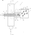
- FIG. 3 is a sectional view of the manufacturing apparatus 1 for manufacturing the carrier powder, which passes through the center of the burner 2. It is an enlarged view of the area
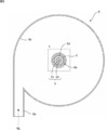
- FIG. 7 is a sectional view taken along line AA in FIG. 6. It is an enlarged view of the area
- Supported metal catalyst 100 As shown in FIGS. 1 to 4, the supported metal catalyst 100 is a carrier powder which is an aggregate of carrier fine particles 150 having a chain portion formed by fusion bonding a plurality of crystallites 120 in a chain shape, The metal fine particles 130 carried by the carrier powder are provided. Each configuration will be described below.
- the carrier fine particles 150 are oxide fine particles containing one or more elements selected from rare earths, alkaline earths, transition metals, niobium, bismuth, tin, antimony, zirconium, molybdenum, indium, tantalum, and tungsten.
- Rare earths, alkaline earths, niobium, bismuth, antimony and tantalum are preferable because they are dopants that improve conductivity, and transition metals are preferable because they are elements that form the matrix that imparts conductivity, and other than the above.
- the elements are preferable because they are elements other than transition metals that constitute the matrix that gives conductivity. Since these fine particles do not dissolve even under strongly acidic conditions, it is preferable that at least one of titanium, iron, niobium, tantalum, zirconium, and tin is contained.
- the carrier fine particles 150 are formed with a branch 160 and a three-dimensional void 110 surrounded by holes existing between the plurality of branches.
- the branch 160 is a portion in which a chain-like portion formed by fusion-bonding a plurality of crystallites 120 constituting the carrier fine particles 150 into a chain is branched as a branch.
- a gas diffusion path for diffusing oxygen, which is an oxidant, and hydrogen, which is a fuel, and transporting it onto the supported metal catalyst 100 is formed by the configuration of the carrier fine particles 150 described above.
- the carrier fine particles 150 have branch points (branch points, sometimes simply referred to as branches hereinafter) b1, b2, b5, A first hole portion surrounded by b4 and b1, a second hole portion surrounded by branch points b1, b2, b3 and b1, a second hole portion surrounded by branch points b2, b3, b6, b7, b5 and b2.
- branch points branch points, sometimes simply referred to as branches hereinafter
- branch points branch points, sometimes simply referred to as branches hereinafter
- branch points b1, b2, b3 and b1 A first hole portion surrounded by branch points b1, b2, b3 and b1, a second hole portion surrounded by branch points b2, b3, b6, b7, b5 and b2.
- Three hole portions, a fourth hole portion surrounded by branch points b1, b3, b6, b7, b5, b4, b1 are provided, so that a total of four hole portions are
- the void 110 is a three-dimensional space surrounded by these four hole surfaces.
- the carrier fine particles 150 have a plurality of holes surrounded by a plurality of branch points connecting a plurality of branches in this way.
- the three-dimensional space (void) surrounded by the plurality of holes is continuously provided. Therefore, this void serves as a gas diffusion path (gas diffusion path) for oxygen and hydrogen.
- FIG. 4 is a diagram showing the gas diffusion path in FIG. FIG. 4 shows an example of the gas diffusion path (gas diffusion path) of the void 110.
- a flow (gas diffusion path) 170 such as an oxidant (gas), a fuel gas, etc. can flow in a desired direction via the void 110 as shown in FIG. That is, the void 110 serves as a gas diffusion path.
- the carrier fine particles 150 may simply have one hole (for example, the first hole surrounded by the branch points b1, b2, b5, b4, b1) as a simple structure.
- the voids 110 are provided by the thickness of the crystallite grains of the crystallite 120.
- the carrier fine particles 150 may have one or more branches. Even in this case, since there is a branch between the carrier fine particles 150, they cannot be adhered to each other, and the void 110 can be provided between them.
- the place described as a hole above may be restated as a closed curve (closed loop).
- the void 110 is surrounded by a closed curved surface including a plurality of branch points (for example, branch points b1 to b7).
- the branch points b1 to b7 may be regarded as the center of gravity of the crystallite of the metal oxide that constitutes the carrier fine particles 150 in which the branches are connected to each other, or may be any one point on the crystallite.
- the size of the crystallite 120 is preferably 10 to 30 nm, more preferably 10 to 15 nm. Specifically, this size is, for example, 10, 11, 12, 13, 14, 15, 16, 17, 18, 19, 20, 25, 30 nm, and is between any two of the numerical values exemplified here. It may be within the range.
- the size (crystallite diameter) of the crystallite 120 can be obtained from the half width of the peak of the XRD pattern based on the Scherrer equation. If the crystallite 120 is too small, the oxide is likely to be eluted and the durability of the catalyst may be reduced. If the crystallite 120 is too large, the volume of the secondary pores becomes small, and the flooding phenomenon may occur easily.
- the aggregate of the carrier fine particles 150 is in powder form. Such an aggregate is referred to as "carrier powder”.
- the average particle size of the carrier fine particles 150 in the carrier powder is preferably 0.1 ⁇ m to 4 ⁇ m, more preferably 0.5 ⁇ m to 2 ⁇ m.
- the average particle size of the carrier fine particles 150 can be measured by a laser diffraction / scattering type particle size distribution measuring device.
- the specific surface area of the carrier powder is preferably 12 m 2 / g or more, more preferably 25 m 2 / g or more.
- the specific surface area is, for example, 12 to 100 m 2 / g, and specifically, for example, 12, 15, 20 , 25, 30, 35, 40, 45, 50, 100 m 2 / g, which is exemplified here. It may be in the range between any two of the numerical values. These values are for fine particles of tin oxide, and when other oxides are used, the true density is different from that of tin oxide, and therefore the values per unit weight are different.
- the true density of tin oxide is 6.95 g / cm 3
- the specific surface area per 1 cm 3 can be converted by multiplying the true density by the above numerical value.
- 12m 2 / g is 83.4 ⁇ 83m 2 / cm 3
- 25m 2 / g becomes 173.75 ⁇ 174m 2 / cm 3.
- this value is, for example, 83, 85, 90, 95, 100, 105, 110, 115, 120, 125, 130, 135, 140, 145, 150, 155, 160, 165, 170 m 2 / cm. 3 , and may be within a range between any two of the numerical values exemplified here.
- the voids 110 included in the carrier powder have primary pores having a pore diameter of 25 nm or less determined by the BJH method and secondary pores having a pore diameter of more than 25 nm and 80 nm or less.
- the volume of the secondary holes is 0.045 cm 3 / g or more. Since this numerical value is also the case of fine particles of tin oxide, in order to generalize it, the numerical value per unit volume of the fine carrier particles constituting the carrier powder will be determined.
- the similarly multiplying the true density of the tin oxide 0.045 cm 3 / g, it has a secondary pore volume of 0.31275 ⁇ 0.313cm 3 / cm 3, and the support powder 1 cm 3 per 0.313Cm 3 become.
- the following numerical values per unit weight can be easily generalized (numerical values per unit volume).
- the primary pores and the secondary pores are deeply related to the discharge of water generated by the catalytic reaction, and the primary pores mainly transport the water generated on the catalyst surface to the secondary pores connected to the primary pores.
- the secondary pores mainly serve to transport the water carried from the primary pores to the outside of the catalyst layer. If the volume of the primary holes and the secondary holes is too small, flooding phenomenon easily occurs. In the present embodiment, since the volume of the secondary holes is a relatively large value of 0.045 cm 3 / g or more, the flooding phenomenon is suppressed.
- the volume of the secondary holes is, for example, 0.045 to 0.100 cm 3 / g, and specifically, for example, 0.045, 0.050, 0.055, 0.060, 0.065, 0.070. , 0.075, 0.080, 0.085, 0.090, 0.095, 0.100 cm 3 / g, and may be in the range between any two of the numerical values exemplified here.
- the volume of the secondary pores is, for example, 0.312 ⁇ 0.695cm 3 / cm 3, specifically, for example, 0.312,0.350,0.400,0 .450, 0.500, 0.550, 0.600, 0.650, 0.695 cm 3 / cm 3 , and may be in the range between any two of the numerical values exemplified here.
- volume of primary hole / volume of secondary hole is preferably 0.80 or less.
- the volume of the secondary holes becomes sufficiently large, and the flooding phenomenon is easily suppressed.
- This value is, for example, 0.10 to 0.80, and specifically, for example, 0.10, 0.15, 0.20, 0.25, 0.30, 0.35, 0.40, 0. .45, 0.50, 0.55, 0.60, 0.65, 0.70, 0.75, 0.80, and is in a range between any two of the numerical values exemplified here. Good.
- the carrier powder preferably has a porosity of 50% or more, more preferably 60% or more.
- the porosity is, for example, 50 to 80%, specifically, for example, 50, 55, 60, 65, 70, 75, 80%, and within a range between any two of the numerical values exemplified here. It may be.
- the porosity can be determined by mercury porosimetry or FIB-SEM.
- the carrier powder preferably has an angle of repose of 50 degrees or less, more preferably 45 degrees or less.
- the carrier powder has the same fluidity as wheat flour and is easy to handle.
- This angle of repose is, for example, 20 to 50 degrees, specifically, for example, 20, 25, 30, 35, 40, 45, 50 degrees, and is within a range between any two of the numerical values exemplified here. May be The angle of repose can be obtained by the drop volume method.
- the conductivity of the carrier powder is preferably 0.001 S / cm or more, more preferably 0.01 S / cm or more.
- This electrical conductivity is, for example, 0.01 to 1000 S / cm, and specifically, for example, 0.01, 0.1, 1, 10, 100, 1000 S / cm, and any of the numerical values exemplified here. It may be in the range between the two.
- the conductivity can be measured based on the JIS standard (JIS K 7194).
- the carrier fine particles 150 have a branch 160 composed of a chain portion formed by fusion bonding a plurality of crystallites 120 in a chain shape, and have a property of allowing electrons to flow. As shown in FIGS. 1 to 4, the carrier fine particles 150 have a plurality of branches 160, and the branches form a network via branch points (b1 to b7) where the branches are connected to each other. Therefore, between them, it has an electrically conductive property. Therefore, the branch 160 of the carrier fine particle 150 shown by a dotted line from the point P0 in FIG. 1 itself constitutes the electron conduction path (electron conduction path) 140.
- the fine metal particles 130 are fine particles of metal (eg, platinum) or alloy that can function as a catalyst.
- the average particle size of the large number of metal fine particles 130 carried on the carrier powder is preferably 1 to 20 nm, more preferably 3 to 10 nm. This average particle diameter is specifically, for example, 1, 2, 3, 4, 5, 6, 7, 8, 9, 10, 11, 12, 13, 14, 15, 16, 17, 18, 19, It is 20 nm, and may be in the range between any two of the numerical values exemplified here. If the average particle size of the metal fine particles 130 is less than 1 nm, it dissolves as the electrode reaction proceeds, and if it exceeds 20 nm, the electrochemically active surface area becomes small and desired electrode performance cannot be obtained.
- the average particle diameter of the metal fine particles 130 can be obtained by measuring the diameters of the circumscribing circles of all the metal fine particles 130 shown in the TEM image of the supported metal catalyst 100 and calculating the arithmetic mean thereof.
- the fine metal particles 130 are made of any metal or alloy having a catalytic ability.
- the fine metal particles 130 are preferably composed of only a noble metal or an alloy of a noble metal and a transition metal.
- the metal fine particles 130 may include a core and a skin layer that covers the core.
- the core preferably comprises an alloy of a noble metal and a transition metal.
- the skin layer preferably contains a noble metal. Platinum is preferable as the noble metal, and cobalt (Co) or nickel (Ni) is preferable as the transition element, and cobalt is particularly preferable.
- the amount of the metal fine particles 130 carried is preferably 1 to 50% by mass, more preferably 5 to 25% by mass. This supported amount is, for example, 1, 5, 10, 15, 20, 25, 30, 35, 40, 45, 50% by mass, and is a range between any two of the numerical values exemplified here. May be inside.
- FIG. 5 shows a model diagram of the fuel cell of the present invention. 5, in the fuel cell (fuel cell) 200, the catalyst layer 220A on the anode 201 side, the gas diffusion layer 210A, the catalyst layer 220K on the cathode 202 side, and the gas diffusion layer 210K are opposed to each other with the electrolyte membrane 230 interposed therebetween. Is composed of.
- the anode side gas diffusion layer 210A, the anode side catalyst layer 220A, the electrolyte membrane 230, the cathode side catalyst layer 220K, and the cathode side gas diffusion layer 210K are arranged in this order.
- the cathode side catalyst layer 220K includes the supported metal catalyst 100.
- the anode-side catalyst layer 220A may also include the supported metal catalyst 100, but may include another catalyst.
- the manufacturing apparatus 1 includes a burner 2, a raw material supply unit 3, a reaction tube 4, a recovery unit 5, and a gas storage unit 6.
- the raw material supply unit 3 includes an outer cylinder 13 and a raw material distribution cylinder 23.
- the burner 2 has a cylindrical shape, and the raw material supply unit 3 is arranged inside the burner 2.
- the burner gas 2a is circulated between the burner 2 and the outer cylinder 13.
- the burner gas 2a is used to form a flame 7 at the tip of the burner 2 by ignition.
- the flame 7 forms a high temperature region of 1000 ° C. or higher.
- the burner gas 2a preferably contains a combustible gas such as propane, methane, acetylene, hydrogen or nitrous oxide.
- a mixed gas of oxygen and propane can be used as the burner gas 2a.
- the temperature in the high temperature region is, for example, 1000 to 2000 ° C., and specifically, for example, 1000, 1100, 1200, 1300, 1400, 1500, 1600, 1700, 1800, 1900, 2000 ° C., and the numerical values exemplified here. It may be within a range between any two.
- a raw material solution 23 a for producing a carrier powder is circulated in the raw material distribution cylinder 23.
- a solution containing a metal compound is used.
- the metal compound include fatty acid metal (Sn, Ti, Nb, Ta, W, etc.) salts.
- the carbon number of the fatty acid is, for example, 2 to 20, preferably 4 to 15, and more preferably 6 to 12.
- metal octylates titanium octylate, niobium octylate, tantalum octylate, tungsten octylate, etc.
- the metal compound is preferably dissolved or dispersed in a non-aqueous solvent.
- the mist-forming gas 13a used for forming the mist of the raw material solution 23a is circulated between the outer cylinder 13 and the raw material distribution cylinder 23.
- the mist forming gas 13a and the raw material solution 23a are jetted together from the tip of the raw material supply unit 3, the raw material solution 23a is misted.
- the mist 23b of the raw material solution 23a is sprayed into the flame 7, and the metal compound in the raw material solution 23a undergoes a thermal decomposition reaction in the flame 7 so that the crystallite 120 is fused and bonded in a chain shape to form a chain portion.
- Carrier powder which is an aggregate of carrier fine particles 150 having, is generated.
- the mist-ized gas 13a is oxygen in one example.
- the reaction tube 4 is provided between the collector 5 and the gas storage section 6. A flame 7 is formed in the reaction tube 4.
- the collector 5 is provided with a filter 5a and a gas discharge part 5b. Negative pressure is applied to the gas discharge part 5b. Therefore, an air flow toward the gas discharge part 5b is generated in the collector 5 and the reaction tube 4.
- the gas storage section 6 is cylindrical and has a cooling gas introduction section 6a and a slit 6b.
- the cooling gas 6g is introduced into the gas storage section 6 from the cooling gas introduction section 6a. Since the cooling gas introduction part 6a is oriented in the direction along the tangent line of the inner peripheral wall 6c of the gas storage part 6, the cooling gas 6g introduced into the gas storage part 6 through the cooling gas introduction part 6a is Turn along 6c.
- a burner insertion hole 6d is provided at the center of the gas storage portion 6. The burner 2 is inserted into the burner insertion hole 6d.
- the slit 6b is provided at a position adjacent to the burner insertion hole 6d so as to surround the burner insertion hole 6d.
- the slit 6b is provided so as to surround the burner 2.
- the cooling gas 6g in the gas storage portion 6 is driven by the negative pressure applied to the gas discharge portion 5b and is discharged toward the reaction tube 4 from the slit 6b.
- the cooling gas 6g may be any gas that can cool the produced oxide, and is preferably an inert gas, for example, air.
- the flow rate of the cooling gas 6g is preferably twice or more the flow rate of the burner gas 2a.
- the upper limit of the flow rate of the cooling gas 6g is not particularly specified, but is, for example, 1000 times the flow rate of the burner gas 2a.
- the flow rate of the cooling gas 6g / the flow rate of the burner gas 2a is, for example, 2 to 1000, and specifically, for example, 2, 5, 10, 15, 20, 25, 30, 35, 40, 45, 50, 100, 200, 500, 1000, and may be in the range between any two of the numerical values exemplified here.
- the cooling gas 6g is caused to flow by applying a negative pressure to the gas discharge part 5b, but the cooling gas 6g may be caused to flow by applying a positive pressure to the cooling gas introduction part 6a.
- the cooling gas 6g since the cooling gas 6g is supplied to the periphery of the flame 7 through the slit 6b, the cooling gas 6g becomes a laminar flow and flows around the flame 7. For this reason, the mist 23b, the crystallites 120, and the carrier fine particles 150 are not disturbed by the cooling gas 6g and are sufficiently heated by the flame 7 while moving along the flame 7 and the reaction proceeds. Further, after the carrier fine particles 150 are emitted from the flame 7, the carrier fine particles 150 are immediately cooled by the cooling gas 6g, so that the structure having the chain-like portion is maintained. The cooled carrier particles 150 are captured and collected by the filter 5a.
- the carrier powder which is an aggregate of the carrier fine particles 150, uses the manufacturing apparatus 1 to form a high temperature region of 1000 ° C. or higher by the flame 7 at the tip of the burner 2, and the cooling gas 6 g is supplied to the high temperature region through the slit 6b. It can be produced by subjecting the metal compound to a thermal decomposition reaction in this high temperature region while supplying it to the surroundings of.
- the high temperature region may be formed by plasma or the like other than the flame 7.
- the method of manufacturing supported metal catalyst 100 includes a carrier powder generating step, a supporting step, a heat treatment step, and a reducing step.
- the carrier powder is produced by the above method.
- the metal fine particles 130 are carried on the carrier powder.
- This loading can be performed using a method such as a reverse micelle method, a colloid method, an impregnation method, or the like.
- metal colloid particles are adsorbed on the carrier powder. More specifically, by preparing a dispersion liquid in which metal colloid particles synthesized by the colloid method are dispersed in an aqueous solution, and adding and mixing the metal colloid particles in the dispersion liquid, the colloid particles on the surface of the carrier powder. Adsorb.
- the carrier powder to which the colloidal particles are adsorbed can be separated from the dispersion medium through filtration and drying.
- heat treatment step heat treatment is performed at 500 to 750 ° C.
- the crystallites of the carrier powder grow and grow in size.
- the carrying step is performed by the colloid method, the colloid particles become the metal fine particles 130.
- This heat treatment is specifically, for example, 500, 550, 600, 650, 700, and 750 ° C., and may be within a range between any two of the numerical values exemplified here.
- crystallites grow, but if the heat treatment temperature is too low, the crystallites 120 of the carrier fine particles 150 do not grow sufficiently and are easily eluted.
- the higher the heat treatment temperature the smaller the secondary pore volume. Therefore, if the heat treatment temperature is too high, the secondary pore volume becomes too small and the flooding phenomenon easily occurs.
- the heat treatment time is, for example, 0.1 to 20 hours, preferably 0.5 to 5 hours. Specifically, this time is, for example, 0.1, 0.5, 1, 2, 3, 4, 5, 6, 7, 8, 9, 10, 15, 20 hours, and the numerical values exemplified here. It may be within a range between any two.
- the heat treatment can be performed in an inert gas atmosphere such as nitrogen or in an inert gas atmosphere containing 1 to 4% hydrogen.
- the reduction treatment of the metal fine particles 130 is performed after the heat treatment step.
- the reduction treatment can be performed by performing heat treatment in a reducing atmosphere containing a reducing gas such as hydrogen.
- the reduction step can be omitted if unnecessary.
- the temperature of this heat treatment is, for example, 70 to 300 ° C, preferably 100 to 200 ° C.
- This temperature is, for example, specifically, 70, 80, 90, 100, 110, 120, 130, 140, 150, 160, 170, 180, 190, 200, 250, 300 ° C., and is exemplified here. It may be in the range between any two of the numerical values.
- the time of this heat treatment is, for example, 0.01 to 20 hours, preferably 0.1 to 5 hours. This time is specifically 0.01, 0.05, 0.1, 0.5, 1, 2, 3, 4, 5, 6, 7, 8, 9, 10, 15, 20 hours. And may be within a range between any two of the numerical values exemplified here.
- the reducing gas is hydrogen
- its concentration is, for example, 0.1 to 100% by volume, preferably 0.2 to 10% by volume, and more preferably 0.5 to 3% by volume.
- This concentration is, for example, 0.1, 0.2, 0.5, 1, 1.5, 2, 2.5, 3, 10, 100% by volume. It may be in the range between any two.
- the metal fine particles 130 after the heat treatment in the heat treatment step may be in an oxidized state, and in that case, the metal fine particles 130 may not show catalytic activity. In this case, the catalytic activity can be increased by reducing the metal fine particles 130.
- Carrier powder was manufactured using the manufacturing apparatus 1 shown in FIGS. 6 to 9.
- the burner gas 2a a gas obtained by mixing 5 L / min of oxygen and 1 L / min of propane gas was used, and this gas was ignited to form a flame (chemical flame) 7 at 1600 ° C. or higher at the tip of the burner 2.
- the raw material solution 23a a solution in which tin octylate and niobium octylate were mixed and dissolved in a mineral split terpene at a molar ratio of 0.95: 0.05 was used.
- Oxygen was used as the mist forming gas 13a.
- the raw material supply unit 3 has a double pipe structure (total length 322.3 mm), oxygen gas is supplied from the outer cylinder 13, a raw material solution 23a is supplied to the raw material distribution cylinder 23, and a fluid nozzle and an air nozzle are provided at the tip of the raw material distribution cylinder 23. Then, there, the raw material solution 23a was made into the mist 23b.
- the recovery amount of the carrier powder was 10 g or more after the operation for 60 minutes.
- the solution was diluted with 150 ml of water and the pH of the solution was adjusted to 5 with NaOH. Then, 25 ml of hydrogen peroxide was added, and the pH was readjusted to 5 with NaOH. Furthermore, a CoCl 2 solution (CoCl 2 (manufactured by Kanto Kagaku) / 15 mL ultrapure water) was added dropwise at 2 mL / min and stirred.
- a CoCl 2 solution CoCl 2 (manufactured by Kanto Kagaku) / 15 mL ultrapure water
- the sample of the heat treatment step was subjected to heat treatment in 1% hydrogen at 150 ° C. for 2 hours to reduce the metal fine particles 130.
- the supported metal catalyst 100 in which the metal fine particles 130 are supported on the carrier powder was obtained.
- Examples 2 to 3 and Comparative Example 1> A supported metal catalyst 100 was obtained in the same manner as in Example 1 except that the heat treatment temperature in step S5 was changed as shown in Table 1.
- BET specific surface area was calculated
- the pore volume distribution was obtained by using the BJH method in the nitrogen gas adsorption process under the conditions of a relative pressure of 0.01 to 0.98 using the above measuring device.
- the total volume of pores having a pore size of 25 nm or less in the obtained distribution was defined as a primary pore volume, and the total volume of pores having a pore size of more than 25 nm and 80 nm or less was defined as a secondary pore volume.
- Examples 1 to 3 which were heat-treated at 500 to 700 ° C. had higher mass activity in a high humidity environment of 80 to 100% humidity than Comparative Example 1 which was heat-treated at 800 ° C. This result is considered to be because the occurrence of the flooding phenomenon was suppressed in Examples 1 to 3 because the secondary pore volume was 0.045 cm 3 / g or more.
- the crystallite size was sufficiently large at 12 to 14 nm, so that the elution of crystallites was sufficiently suppressed.
Landscapes
- Chemical & Material Sciences (AREA)
- Engineering & Computer Science (AREA)
- Chemical Kinetics & Catalysis (AREA)
- Materials Engineering (AREA)
- Organic Chemistry (AREA)
- General Chemical & Material Sciences (AREA)
- Electrochemistry (AREA)
- Manufacturing & Machinery (AREA)
- Physics & Mathematics (AREA)
- Thermal Sciences (AREA)
- Catalysts (AREA)
- Nanotechnology (AREA)
- Crystallography & Structural Chemistry (AREA)
- Inert Electrodes (AREA)
- Fuel Cell (AREA)
Abstract
高湿環境下でのセル性能を向上させることが可能な担体粉末を提供する。 本発明によれば、担体粉末と、前記担体粉末に担持された金属微粒子とを備える担持金属触媒であって、前記担体粉末は、担体微粒子の集合体であり、前記担体微粒子は、酸化物の微粒子であり、且つ複数の結晶子が鎖状に融着結合されて構成された鎖状部を備え、前記結晶子は、サイズが10~30nmであり、前記担体粉末は、空隙を備え、前記空隙は、BJH法によって決定される細孔径が25nm超80nm以下である二次孔を有し、前記担体粉末を構成する前記担体微粒子の単位体積あたりの前記二次孔の体積が0.313cm3/cm3以上である、担持金属触媒が提供される。
Description
本発明は、担持金属触媒及びその製造方法に関する。本発明の担持金属触媒は、燃料電池のカソード電極触媒として好適に用いられる。
非特許文献1には、火炎法によって製造したNb-SnO2ナノ粒子を800℃で熱処理することによって担体粉末を製造し、この担体粉末を用いてカソード電極触媒を製造する技術が開示されている。
J. Electrochem. Soc. 2015 volume 162, issue 7, F736-F743
非特許文献1には、Nb-SnO2にPtを担持した触媒に黒鉛化カーボンブラックを添加することによって、高湿環境下でのセル性能が向上する点が開示されている。しかし、黒鉛化カーボンブラックの添加は、触媒の長期安定性を損なう虞があるので、黒鉛化カーボンブラックを添加することなく、高湿環境下でのセル性能を向上させることが望まれている。
本発明はこのような事情に鑑みてなされたものであり、高湿環境下でのセル性能を向上させることが可能な担体粉末を提供するものである。
本発明によれば、担体粉末と、前記担体粉末に担持された金属微粒子とを備える担持金属触媒であって、前記担体粉末は、担体微粒子の集合体であり、前記担体微粒子は、酸化物の微粒子であり、且つ複数の結晶子が鎖状に融着結合されて構成された鎖状部を備え、前記結晶子は、サイズが10~30nmであり、前記担体粉末は、空隙を備え、前記空隙は、BJH法によって決定される細孔径が25nm超80nm以下である二次孔を有し、前記担体粉末を構成する前記担体微粒子の単位体積あたりの前記二次孔の体積が0.313cm3/cm3以上である、担持金属触媒が提供される。
本発明者らが鋭意検討を行ったところ、高湿環境下でのセル性能が低下するのは、触媒反応に伴って発生する水が触媒中の細孔に詰まってしまうフラッディング現象によるものであることが分かった。そして、この知見に基づき、担体微粒子を構成する結晶子のサイズが10nm以上であり、且つ二次孔の体積が0.313cm3/cm3以上である場合には、触媒反応に伴って発生する水が触媒外に速やかに排出されるためにフラッディング現象が抑制されるので、黒鉛化カーボンブラックを添加することなく、高湿環境下でのセル性能を向上させることができることを見出し、本発明の完成に到った。
以下、図面を用いて本発明の実施形態について説明する。以下に示す実施形態中で示した各種特徴事項は、互いに組み合わせ可能である。また、各特徴事項について独立して発明が成立する。
1.担持金属触媒100
図1~図4に示すように、担持金属触媒100は、複数の結晶子120が鎖状に融着結合されて構成された鎖状部を有する担体微粒子150の集合体である担体粉末と、担体粉末に担持される金属微粒子130とを備える。以下、各構成について説明する。
図1~図4に示すように、担持金属触媒100は、複数の結晶子120が鎖状に融着結合されて構成された鎖状部を有する担体微粒子150の集合体である担体粉末と、担体粉末に担持される金属微粒子130とを備える。以下、各構成について説明する。
1-1.担体微粒子150及び担体粉末
担体微粒子150は、希土類、アルカリ土類、遷移金属、ニオブ、ビスマス、スズ、アンチモン、ジルコニウム、モリブデン、インジウム、タンタル、タングステンから選ばれる一種以上の元素を含む酸化物の微粒子である。希土類、アルカリ土類、ニオブ、ビスマス、アンチモン、タンタルは導電性を向上させるド―パントになる理由により好ましく、遷移金属は導電性を与える母体を構成する元素になる理由により好ましく、上記の他の元素は遷移金属以外でありながら導電性を与える母体を構成する元素になる理由により好ましい。なお、これら微粒子は強酸性条件下でも溶解しないことから、チタン、鉄、ニオブ、タンタル、ジルコニウム、スズのうち少なくとも一種類が含有されていることが好ましい。
担体微粒子150は、希土類、アルカリ土類、遷移金属、ニオブ、ビスマス、スズ、アンチモン、ジルコニウム、モリブデン、インジウム、タンタル、タングステンから選ばれる一種以上の元素を含む酸化物の微粒子である。希土類、アルカリ土類、ニオブ、ビスマス、アンチモン、タンタルは導電性を向上させるド―パントになる理由により好ましく、遷移金属は導電性を与える母体を構成する元素になる理由により好ましく、上記の他の元素は遷移金属以外でありながら導電性を与える母体を構成する元素になる理由により好ましい。なお、これら微粒子は強酸性条件下でも溶解しないことから、チタン、鉄、ニオブ、タンタル、ジルコニウム、スズのうち少なくとも一種類が含有されていることが好ましい。
図1~図3に示すように、担体微粒子150には、その分枝160及びその複数の分枝間に存在する孔で取り囲まれた立体的な空隙110が形成されている。分枝160は、担体微粒子150を構成する複数の結晶子120が鎖状に融着結合されて構成された鎖状部が枝として分かれた部分である。酸化剤である酸素及びまたは燃料である水素を拡散させ、担持金属触媒100上へ輸送するガス拡散経路を上記した担体微粒子150の立体配置により形成されている。
図1~図3に担持金属触媒の構造モデルの例として示したように、担体微粒子150は、分枝同士がつながる点(分岐点、以下単に分岐と称す場合もあり)b1、b2、b5、b4、b1で囲まれた第1の孔部、分岐点b1、b2、b3、b1で囲まれた第2の孔部、分岐点b2、b3、b6、b7、b5、b2で囲まれた第3の孔部、分岐点b1、b3、b6、b7、b5、b4、b1で囲まれた第4の孔部の計4つの孔部を備える。ここで各孔部(第1~第4の孔部)の分岐点で囲まれた面を孔面とすると、空隙110はこれら4つの孔面で囲まれる立体的空間である。担体微粒子150は、このように複数の分枝同士がつながる複数の分岐点で囲まれる孔部を複数備える。そして複数の孔部によって囲まれる立体的空間(空隙)が互いに連続して備えられた構造となっている。したがってこの空隙が酸素や水素などのガス拡散径路(ガス拡散パス)となる。図4は、図1におけるガス拡散径路を示す図である。図4では、空隙110のガス拡散径路(ガス拡散パス)の一例を示している。酸化剤(ガス)、燃料ガス等の流れ(ガス拡散径路)170は図4に示すように空隙110を介して所望の方向に流れることができる。つまりこの空隙110がガス拡散径路となる。
なお、担体微粒子150の簡素な構成としては、単に1つの孔部(たとえば分岐点b1、b2、b5、b4、b1で囲まれた第1の孔部)を備えるようにしてもよい。この場合は、結晶子120の結晶子粒の厚みの分の空隙110を備えることになる。さらに簡素な構成としては、担体微粒子150は1つ以上の分枝を持つものであってもよい。この場合であっても担体微粒子150同士間に分枝があるために密着できずその間に空隙110を備えることができる。
なお、上記で孔部と記したところは、閉曲線(クローズドループ)と言い換えてもよい。あるいは、複数の上述した分岐点(たとえば分岐点b1~b7)を含む閉曲面に囲まれた空隙110を有すると言い換えることもできる。分岐点b1~b7としては、分枝同士がつながる担体微粒子150を構成する金属酸化物の結晶子の重心としてとらえることもできるし、あるいはこの結晶子上の任意の1点としてもよい。
結晶子120のサイズは、10~30nmが好ましく、10~15nmがさらに好ましい。このサイズは、具体的には例えば、10、11、12、13、14、15、16、17、18、19、20、25、30nmであり、ここで例示した数値の何れか2つの間の範囲内であってもよい。結晶子120のサイズ(結晶子径)は、XRDパターンのピークの半値幅からシェラー式に基づいて求めることができる。結晶子120が小さすぎると酸化物が溶出されやすくなって触媒の耐久性が低下する虞がある。結晶子120が大きすぎると二次孔体積が小さくなってフラッディング現象が起こりやすくなる虞がある。
担体微粒子150の集合体は、粉末状である。このような集合体を「担体粉末」と称する。
担体粉末中の担体微粒子150の平均粒子径は、0.1μm~4μmが好ましく、0.5μm~2μmがさらに好ましい。担体微粒子150の平均粒子径は、レーザ回折/散乱式粒子径分布測定装置によって測定することができる。
以下、担体微粒子として酸化スズの微粒子を用いた場合について説明する。担体粉末の比表面積は、12m2/g以上が好ましく、25m2/g以上がさらに好ましい。この比表面積は、例えば12~100m2/gであり、具体的には例えば、12、15、20、25、30、35、40、45、50、100m2/gであり、ここで例示した数値の何れか2つの間の範囲内であってもよい。これらの数値は酸化スズの微粒子の場合であり、他の酸化物を用いた場合は、酸化スズと真密度が異なるため単位重量当たりの数値は異なる。従って、一般化するために、担体粉末を構成する担体微粒子の単位体積あたりの数値に換算する。酸化スズの真密度は、6.95g/cm3であるので、この真密度を上述した数値に掛け合わせれば1cm3あたりの比表面積に換算できる。例えば、12m2/gは83.4≒83m2/cm3、25m2/gは173.75≒174m2/cm3になる。この値は、具体的には例えば、83、85、90、95、100、105、110、115、120、125、130、135、140、145、150、155、160、165、170m2/cm3であり、ここで例示した数値の何れか2つの間の範囲内であってもよい。
担体粉末に含まれる空隙110は、BJH法によって決定される細孔径が25nm以下である一次孔と、細孔径が25nm超80nm以下である二次孔を有する。二次孔の体積は、0.045cm3/g以上である。この数値も酸化スズの微粒子の場合であるので、一般化するために担体粉末を構成する担体微粒子の単位体積あたりの数値を求めることにする。同様に酸化スズの真密度を掛け合わせると、0.045cm3/gは、0.31275≒0.313cm3/cm3となり、担体粉末1cm3あたり0.313cm3の二次孔体積を有することになる。同様に、以下に示す単位重量あたりの数値も容易に一般化(単位体積あたりの数値)することができる。
ところで、一次孔及び二次孔は、触媒反応に伴って発生する水の排出に深く関わっており、一次孔は主に触媒表面で生成した水をその一次孔に連結する二次孔へ輸送する働きをしており、二次孔は主に一次孔から運ばれた水を触媒層外に輸送する働きをする。それら一次孔及び二次孔の体積が小さすぎると、フラッディング現象が起こりやすい。本実施形態では、二次孔の体積が0.045cm3/g以上という比較的大きな値であるので、フラッディング現象が抑制される。二次孔の体積は、例えば0.045~0.100cm3/gであり、具体的には例えば、0.045、0.050、0.055、0.060、0.065、0.070、0.075、0.080、0.085、0.090、0.095、0.100cm3/gであり、ここで例示した数値の何れか2つの間の範囲内であってもよい。他の酸化物に一般化すると、二次孔の体積は、例えば0.312~0.695cm3/cm3であり、具体的には例えば、0.312、0.350、0.400、0.450、0.500、0.550、0.600、0.650、0.695cm3/cm3であり、ここで例示した数値の何れか2つの間の範囲内であってもよい。
ところで、一次孔及び二次孔は、触媒反応に伴って発生する水の排出に深く関わっており、一次孔は主に触媒表面で生成した水をその一次孔に連結する二次孔へ輸送する働きをしており、二次孔は主に一次孔から運ばれた水を触媒層外に輸送する働きをする。それら一次孔及び二次孔の体積が小さすぎると、フラッディング現象が起こりやすい。本実施形態では、二次孔の体積が0.045cm3/g以上という比較的大きな値であるので、フラッディング現象が抑制される。二次孔の体積は、例えば0.045~0.100cm3/gであり、具体的には例えば、0.045、0.050、0.055、0.060、0.065、0.070、0.075、0.080、0.085、0.090、0.095、0.100cm3/gであり、ここで例示した数値の何れか2つの間の範囲内であってもよい。他の酸化物に一般化すると、二次孔の体積は、例えば0.312~0.695cm3/cm3であり、具体的には例えば、0.312、0.350、0.400、0.450、0.500、0.550、0.600、0.650、0.695cm3/cm3であり、ここで例示した数値の何れか2つの間の範囲内であってもよい。
一次孔の体積/二次孔の体積の値は、0.80以下であることが好ましい。この場合に、二次孔の体積が十分に大きくなって、フラッディング現象が抑制されやすい。この値は、例えば0.10~0.80であり、具体的には例えば、0.10、0.15、0.20、0.25、0.30、0.35、0.40、0.45、0.50、0.55、0.60、0.65、0.70、0.75、0.80であり、ここで例示した数値の何れか2つの間の範囲内であってもよい。
担体粉末は、空隙率が50%以上であることが好ましく、60%以上であることがさらに好ましい。空隙率は、例えば50~80%であり、具体的には例えば、50、55、60、65、70、75、80%であり、ここで例示した数値の何れか2つの間の範囲内であってもよい。空隙率は、水銀圧入法またはFIB-SEMによって求めることができる。
担体粉末は、安息角が50度以下であることが好ましく、45度以下であることがさらに好ましい。この場合、担体粉末は小麦粉と同程度の流動性を有しており、取り扱いが容易である。この安息角は、例えば20~50度であり、具体的には例えば、20、25、30、35、40、45、50度であり、ここで例示した数値の何れか2つの間の範囲内であってもよい。安息角は、落下体積法によって求めることができる。
担体粉末の導電率は、0.001S/cm以上であることが好ましく、0.01S/cm以上であることがさらに好ましい。この導電率は、例えば0.01~1000S/cmであり、具体的には例えば、0.01、0.1、1、10、100、1000S/cmであり、ここで例示した数値の何れか2つの間の範囲内であってもよい。導電率は、JIS規格(JIS K 7194)に基づいて測定することができる。
担体微粒子150は、複数の結晶子120が鎖状に融着結合されて構成された鎖状部からなる分枝160を有しており、これ自身が電子を流す性質を備える。担体微粒子150は図1~図4に示すように、複数の分枝160を持ち、分枝同士が互いにつながる分岐点(b1~b7)を介して分枝同士がネットワークを組んだ状態となっており、これらの間は電気的に導電性の性質を有することになる。従って図1のP0点から点線で示した担体微粒子150の分枝160は、これ自体が電子伝導径路(電子伝導パス)140を構成している。
1-2.金属微粒子130
金属微粒子130は、触媒として機能しうる金属(例:白金)又は合金の微粒子である。担体粉末に担持される多数の金属微粒子130の平均粒子径は、1~20nmであることが好ましく、3~10nmであることがさらに好ましい。この平均粒子径は、具体的には例えば、1、2、3、4、5、6、7、8、9、10、11、12、13、14、15、16、17、18、19、20nmであり、ここで例示した数値の何れか2つの間の範囲内であってもよい。金属微粒子130の平均粒子径が1nm未満であれば、電極反応の進行と共に溶解し、また20nmより大きくなると電気化学的活性表面積が小さくなり所望の電極性能が得られない。金属微粒子130の平均粒子径は、担持金属触媒100のTEM画像に写っている全ての金属微粒子130の外接円の直径を測定し、その算術平均によって求めることができる。
金属微粒子130は、触媒として機能しうる金属(例:白金)又は合金の微粒子である。担体粉末に担持される多数の金属微粒子130の平均粒子径は、1~20nmであることが好ましく、3~10nmであることがさらに好ましい。この平均粒子径は、具体的には例えば、1、2、3、4、5、6、7、8、9、10、11、12、13、14、15、16、17、18、19、20nmであり、ここで例示した数値の何れか2つの間の範囲内であってもよい。金属微粒子130の平均粒子径が1nm未満であれば、電極反応の進行と共に溶解し、また20nmより大きくなると電気化学的活性表面積が小さくなり所望の電極性能が得られない。金属微粒子130の平均粒子径は、担持金属触媒100のTEM画像に写っている全ての金属微粒子130の外接円の直径を測定し、その算術平均によって求めることができる。
金属微粒子130は、触媒能を有する任意の金属又は合金で構成される。金属微粒子130は、貴金属のみ、又は貴金属と遷移金属の合金で構成されることが好ましい。金属微粒子130は、コアと、これを被覆するスキン層を備えてもよい。コアは、貴金属と遷移金属の合金を含むことが好ましい。スキン層は、貴金属を含むことが好ましい。貴金属としては、白金が好ましく、遷移元素としてはコバルト(Co)あるいはニッケル(Ni)が好ましく、特にコバルトが好適である。
金属微粒子130の担持量は、1~50質量%が好ましく、5~25質量%がさらに好ましい。この担持量は、具体的には例えば、1、5、10、15、20、25、30、35、40、45、50質量%であり、ここで例示した数値の何れか2つの間の範囲内であってもよい。
2.燃料電池200
図5に本発明の燃料電池のモデル図を示す。図5において、燃料電池(燃料電池セル)200は、電解質膜230を挟んでアノード201側の触媒層220A、ガス拡散層210Aとカソード202側の触媒層220K、ガス拡散層210Kがそれぞれ対向するように構成される。アノード側ガス拡散層210A、アノード側触媒層220A、電解質膜230、カソード側触媒層220K、カソード側ガス拡散層210Kがこの順に並ぶ構成である。カソード側触媒層220Kは、担持金属触媒100を含む。アノード側の触媒層220Aも担持金属触媒100を含んでもよいが、別の触媒を含んでもよい。固体高分子形燃料電池200のアノード201とカソード202の間に負荷203を接続することにより、負荷203に対し電力を出力する。
図5に本発明の燃料電池のモデル図を示す。図5において、燃料電池(燃料電池セル)200は、電解質膜230を挟んでアノード201側の触媒層220A、ガス拡散層210Aとカソード202側の触媒層220K、ガス拡散層210Kがそれぞれ対向するように構成される。アノード側ガス拡散層210A、アノード側触媒層220A、電解質膜230、カソード側触媒層220K、カソード側ガス拡散層210Kがこの順に並ぶ構成である。カソード側触媒層220Kは、担持金属触媒100を含む。アノード側の触媒層220Aも担持金属触媒100を含んでもよいが、別の触媒を含んでもよい。固体高分子形燃料電池200のアノード201とカソード202の間に負荷203を接続することにより、負荷203に対し電力を出力する。
3.担体粉末の製造方法
まず、図6~図9を用いて、担体粉末の製造に利用可能な製造装置1について説明する。製造装置1は、バーナー2と、原料供給部3と、反応筒4と、回収器5と、ガス貯留部6を備える。原料供給部3は、外筒13と、原料流通筒23を備える。
まず、図6~図9を用いて、担体粉末の製造に利用可能な製造装置1について説明する。製造装置1は、バーナー2と、原料供給部3と、反応筒4と、回収器5と、ガス貯留部6を備える。原料供給部3は、外筒13と、原料流通筒23を備える。
バーナー2は、筒状であり、原料供給部3は、バーナー2の内部に配置されている。バーナー2と外筒13の間にバーナーガス2aが流通される。バーナーガス2aは、着火により、バーナー2の先端に火炎7を形成するために用いられる。火炎7によって、1000℃以上の高温領域が形成される。バーナーガス2aは、プロパン、メタン、アセチレン、水素もしくは亜酸化窒素等の可燃性ガスを含むことが好ましい。一例では、バーナーガス2aとして、酸素及びプロパンの混合ガスを用いることができる。高温領域の温度は、例えば1000~2000℃であり、具体的には例えば、1000、1100、1200、1300、1400、1500、1600、1700、1800、1900、2000℃であり、ここで例示した数値の何れか2つの間の範囲内であってもよい。
原料流通筒23には、担体粉末を生成するための原料溶液23aが流通される。原料溶液23aとしては、金属化合物を含むものが用いられる。金属化合物としては、脂肪酸金属(Sn,Ti,Nb,Ta,Wなど)塩が例示される。脂肪酸の炭素数は、例えば2~20であり、4~15が好ましく、6~12がさらに好ましい。脂肪酸金属塩としては、オクチル酸金属塩(オクチル酸スズ、オクチル酸チタン、オクチル酸ニオブ、オクチル酸タンタル、オクチル酸タングステンなど)が好ましい。原料溶液23a中において、金属化合物は、非水溶媒中に溶解又は分散されることが好ましい。
外筒13と原料流通筒23の間には、原料溶液23aのミスト化に用いられるミスト化ガス13aが流通される。ミスト化ガス13aと原料溶液23aを原料供給部3の先端から一緒に噴出させると、原料溶液23aがミスト化される。原料溶液23aのミスト23bは、火炎7中に噴霧され、原料溶液23a中の金属化合物が火炎7中で熱分解反応して結晶子120が鎖状に融着結合されて構成された鎖状部を有する担体微粒子150の集合体である担体粉末が生成される。ミスト化ガス13aは、一例では、酸素である。
反応筒4は、回収器5とガス貯留部6の間に設けられている。反応筒4内に火炎7が形成される。回収器5にはフィルタ5aと、ガス排出部5bが設けられている。ガス排出部5bには陰圧が加えられる。このため、回収器5及び反応筒4内にガス排出部5bに向かう気流が生成される。
ガス貯留部6は、筒状であり、冷却ガス導入部6aと、スリット6bを備える。冷却ガス導入部6aから冷却ガス6gがガス貯留部6内に導入される。冷却ガス導入部6aは、ガス貯留部6の内周壁6cの接線に沿った方向に向けられているので、冷却ガス導入部6aを通じてガス貯留部6内に導入された冷却ガス6gは、内周壁6cに沿って旋回する。ガス貯留部6の中央にはバーナー挿通孔6dが設けられている。バーナー挿通孔6dにはバーナー2が挿通される。スリット6bは、バーナー挿通孔6dに隣接した位置に、バーナー挿通孔6dを取り囲むように設けられている。このため、バーナー挿通孔6dにバーナー2を挿通させた状態では、スリット6bは、バーナー2を取り囲むように設けられる。ガス貯留部6内の冷却ガス6gは、ガス排出部5bに加えられた陰圧によって駆動されて、スリット6bから反応筒4に向けて排出される。冷却ガス6gは、生成された酸化物を冷却可能なものであればよく、不活性ガスが好ましく、例えば空気である。冷却ガス6gの流速は、バーナーガス2aの流速の2倍以上が好ましい。冷却ガス6gの流速の上限は、特に規定されないが、例えば、バーナーガス2aの流速の1000倍である。冷却ガス6gの流速/バーナーガス2aの流速は、例えば2~1000であり、具体的には例えば、2、5、10、15、20、25、30、35、40、45、50、100、200、500、1000であり、ここで例示した数値の何れか2つの間の範囲内であってもよい。なお、本実施形態では、ガス排出部5bに陰圧を加えて冷却ガス6gを流しているが、冷却ガス導入部6aに陽圧を加えて冷却ガス6gを流すようにしてもよい。
本実施形態では、スリット6bを通じて火炎7の周囲に冷却ガス6gを供給しているので、冷却ガス6gが層流になって火炎7の周囲を流れる。このために、ミスト23b,結晶子120、及び担体微粒子150が冷却ガス6gによって撹乱されず、火炎7に沿って移動しながら火炎7によって十分に加熱されて反応が進む。また、担体微粒子150が火炎7から出た後は担体微粒子150が冷却ガス6gによって即座に冷却されるので、鎖状部を有する構造が維持される。冷却された担体微粒子150は、フィルタ5aによって捕捉されて回収される。
本実施形態では、担体微粒子150の集合体である担体粉末は、製造装置1を用い、バーナー2の先端に火炎7によって1000℃以上の高温領域を形成し、スリット6bを通じて冷却ガス6gを高温領域の周囲に供給しつつ、この高温領域において金属化合物を熱分解反応させることによって製造することができる。高温領域は、火炎7以外にも、プラズマなどによって形成してもよい。
4.担持金属触媒100の製造方法
担持金属触媒100の製造方法は、担体粉末生成工程と、担持工程と、熱処理工程と、還元工程を備える。
担持金属触媒100の製造方法は、担体粉末生成工程と、担持工程と、熱処理工程と、還元工程を備える。
<担体粉末生成工程>
担体粉末生成工程では、上述の方法で担体粉末を生成する。
担体粉末生成工程では、上述の方法で担体粉末を生成する。
<担持工程>
担持工程では、担体粉末に金属微粒子130を担持させる。この担持は、逆ミセル法、コロイド法、含浸法などの手法を用いて行うことができる。
担持工程では、担体粉末に金属微粒子130を担持させる。この担持は、逆ミセル法、コロイド法、含浸法などの手法を用いて行うことができる。
コロイド法では、担体粉末に金属コロイド粒子を吸着させる。より具体的には、コロイド法で合成した金属コロイド粒子を水溶液中に分散させた分散液を調製し、前記分散液中に金属コロイド粒子を添加及び混合することで、担体粉末表面に前記コロイド粒子を吸着させる。コロイド粒子を吸着させた担体粉末はろ過と乾燥を経て、分散媒と分離することができる。
<熱処理工程>
熱処理工程では、500~750℃で熱処理を行う。これによって、担体粉末の結晶子が結晶成長してそのサイズが大きくなる。また、担持工程をコロイド法によって行った場合、コロイド粒子が金属微粒子130となる。この熱処理は、具体的には例えば、500、550、600、650、700、750℃であり、ここで例示した数値の何れか2つの間の範囲内であってもよい。この熱処理工程の際に、結晶子が結晶成長するが、熱処理温度が低すぎると担体微粒子150の結晶子120が十分に成長せず、溶出されやすくなる。一方、熱処理温度が高いほど二次孔体積が小さくなるので、熱処理温度が高すぎると、二次孔体積が小さくなりすぎて、フラッディング現象が起こりやすくなる。
熱処理工程では、500~750℃で熱処理を行う。これによって、担体粉末の結晶子が結晶成長してそのサイズが大きくなる。また、担持工程をコロイド法によって行った場合、コロイド粒子が金属微粒子130となる。この熱処理は、具体的には例えば、500、550、600、650、700、750℃であり、ここで例示した数値の何れか2つの間の範囲内であってもよい。この熱処理工程の際に、結晶子が結晶成長するが、熱処理温度が低すぎると担体微粒子150の結晶子120が十分に成長せず、溶出されやすくなる。一方、熱処理温度が高いほど二次孔体積が小さくなるので、熱処理温度が高すぎると、二次孔体積が小さくなりすぎて、フラッディング現象が起こりやすくなる。
熱処理時間は、例えば0.1~20時間であり、0.5~5時間が好ましい。この時間は、具体的には例えば、0.1、0.5、1、2、3、4、5、6、7、8、9、10、15、20時間であり、ここで例示した数値の何れか2つの間の範囲内であってもよい。
熱処理は、窒素などの不活性ガス雰囲気下や1~4%の水素を含む不活性ガス雰囲気下で行うことができる。
<還元工程>
還元工程では、熱処理工程の後に、金属微粒子130の還元処理が行われる。還元処理は、水素などの還元性ガスを含む還元性雰囲気下で、熱処理を行うことによって行うことができる。還元工程は不要な場合に省略可能である。
還元工程では、熱処理工程の後に、金属微粒子130の還元処理が行われる。還元処理は、水素などの還元性ガスを含む還元性雰囲気下で、熱処理を行うことによって行うことができる。還元工程は不要な場合に省略可能である。
この熱処理の温度は、例えば70~300℃であり、100~200℃が好ましい。この温度は、例えば具体的には例えば、70、80、90、100、110、120、130、140、150、160、170、180、190、200、250、300℃であり、ここで例示した数値の何れか2つの間の範囲内であってもよい。
この熱処理の時間は、例えば0.01~20時間であり、0.1~5時間が好ましい。この時間は、具体的には例えば、0.01、0.05、0.1、0.5、1、2、3、4、5、6、7、8、9、10、15、20時間であり、ここで例示した数値の何れか2つの間の範囲内であってもよい。
還元性ガスが水素である場合、その濃度は、例えば0.1~100体積%であり、0.2~10体積%が好ましく、0.5~3体積%がさらに好ましい。この濃度は、具体的には例えば、0.1、0.2、0.5、1、1.5、2、2.5、3、10、100体積%であり、ここで例示した数値の何れか2つの間の範囲内であってもよい。
熱処理工程での熱処理後の金属微粒子130は、酸化された状態になっている場合があり、その場合、金属微粒子130が触媒活性を示さない場合がある。この場合、金属微粒子130の還元を行うことによってその触媒活性を高めることができる。
以下に示す方法で担持金属触媒を製造し、各種評価を行った。
1.担持金属触媒100の製造
<実施例1>
(担体粉末の製造)
図6~図9に示す製造装置1を用いて、担体粉末の製造を行った。バーナーガス2aとしては、酸素5L/分、プロパンガス1L/分を混合したガスを用い、このガスに着火してバーナー2の先端に1600℃以上の火炎(化学炎)7を形成した。原料溶液23aとしては、オクチル酸スズおよびオクチル酸ニオブをモル比で0.95:0.05の割合でミネラルスプリットターペンに混合し、溶解させたものを用いた。ミスト化ガス13aとしては、酸素を用いた。9L/分のミスト化ガス13aと、3g/分の原料溶液23aを混合し、スプレーノズル(アトマイザー)である原料供給部3の先端から火炎中心部分に噴霧し、燃焼させ、担体微粒子150の集合体である担体粉末を生成させた。その際、ガス排出部5bを負圧にすることによって、スリット6bから空気を170L/分の流量で吸引することで、生成した担体粉末を回収器5(フィルタ5a付き)に回収した。原料供給部3は、二重管構造(全長322.3mm)からなり外筒13から酸素ガス、原料流通筒23には原料溶液23aが供給され、原料流通筒23先端にはフルイドノズル、エアノズルがあり、そこで、原料溶液23aをミスト23bにした。担体粉末の回収量は60分間の運転で10g以上であった。
(金属微粒子130の担持、熱処理及び還元)
次に、金属微粒子130を担体粉末に担持させ、熱処理及び還元を行った。
次に、金属微粒子130を担体粉末に担持させ、熱処理及び還元を行った。
<担持工程>
まず、塩化白金酸六水和物水溶液0.57mLを38mlの超純水に溶解させ、更に炭酸ナトリウム1.76gを加え撹拌した。
まず、塩化白金酸六水和物水溶液0.57mLを38mlの超純水に溶解させ、更に炭酸ナトリウム1.76gを加え撹拌した。
その溶液を150mlの水で希釈し、NaOHを用いて溶液のpHを5に調整した。その後、過酸化水素を25ml加え、NaOHでpHを5に再調整した。更にCoCl2溶液(CoCl2 (関東化学製)/15mL超純水)を2mL/分で滴下して撹拌した。
その分散液に15mLの超純水に0.50gの担体粉末を分散させた分散液を加え、90℃にて3時間撹拌した。室温まで冷却した後、濾過及び超純水及びアルコールでの洗浄を行い、80℃にて一晩乾燥し、金属微粒子130を担体粉末に担持させた。
<熱処理工程>
熱処理工程では、担持工程後の試料に対して、窒素中で700℃で2時間の熱処理行った。
熱処理工程では、担持工程後の試料に対して、窒素中で700℃で2時間の熱処理行った。
<還元工程>
還元工程では、熱処理工程の試料に対して、1%水素中で150℃で2時間の熱処理を行って金属微粒子130を還元した。
還元工程では、熱処理工程の試料に対して、1%水素中で150℃で2時間の熱処理を行って金属微粒子130を還元した。
以上の工程によって、金属微粒子130が担体粉末に担持された担持金属触媒100が得られた。
<実施例2~3及び比較例1>
ステップS5での熱処理温度を表1に示すように変更した以外は、実施例1と同様の方法で担持金属触媒100を得た。
ステップS5での熱処理温度を表1に示すように変更した以外は、実施例1と同様の方法で担持金属触媒100を得た。
2.各種評価
<結晶子サイズの測定>
結晶子サイズは、XRDパターンのピークの半値幅からシェラー式に基づいて求めた。
<結晶子サイズの測定>
結晶子サイズは、XRDパターンのピークの半値幅からシェラー式に基づいて求めた。
<BET比表面積、一次孔体積及び二次孔体積の測定>
・前処理
サンプル0.2gを測定ガラスセルに量り取り、130℃減圧条件で30mmTorr以下になるまで1~2時間ほど脱水した。その後、室温まで徐冷し、窒素パージした。
・前処理
サンプル0.2gを測定ガラスセルに量り取り、130℃減圧条件で30mmTorr以下になるまで1~2時間ほど脱水した。その後、室温まで徐冷し、窒素パージした。
・測定条件
マイクロメリティクスTriStar3000測定装置を用い相対気圧0.01から0.30の条件にてBET法によりBET比表面積を求めた。上記測定装置を用い相対気圧0.01から0.98の条件にて、窒素ガス吸着過程におけるBJH法を用いて細孔容積分布を得た。得られた分布での細孔径が25nm以下である細孔の体積の合計を一次孔体積とし、細孔径が25nm超80nm以下である細孔の体積の合計を二次孔体積とした。
マイクロメリティクスTriStar3000測定装置を用い相対気圧0.01から0.30の条件にてBET法によりBET比表面積を求めた。上記測定装置を用い相対気圧0.01から0.98の条件にて、窒素ガス吸着過程におけるBJH法を用いて細孔容積分布を得た。得られた分布での細孔径が25nm以下である細孔の体積の合計を一次孔体積とし、細孔径が25nm超80nm以下である細孔の体積の合計を二次孔体積とした。
<質量活性>
日本自動車研究所(JARI)による標準セルによって、80℃、湿度100%の条件での質量活性を求めた。
日本自動車研究所(JARI)による標準セルによって、80℃、湿度100%の条件での質量活性を求めた。

3.考察
500~700℃で熱処理を行った実施例1~3は、800℃で熱処理を行った比較例1に比べて、湿度80~100%という高湿環境での質量活性が高かった。この結果は、実施例1~3は二次孔体積が0.045cm3/g以上であるためにフラッディング現象の発生が抑制されたためであると考えられる。また、実施例1~3では、結晶子サイズが12~14nmという十分な大きさであるので、結晶子の溶出が十分に抑制される。
500~700℃で熱処理を行った実施例1~3は、800℃で熱処理を行った比較例1に比べて、湿度80~100%という高湿環境での質量活性が高かった。この結果は、実施例1~3は二次孔体積が0.045cm3/g以上であるためにフラッディング現象の発生が抑制されたためであると考えられる。また、実施例1~3では、結晶子サイズが12~14nmという十分な大きさであるので、結晶子の溶出が十分に抑制される。
1:製造装置、2:バーナー、2a:バーナーガス、3:原料供給部、4:反応筒、5:回収器、5a:フィルタ、5b:ガス排出部、6:ガス貯留部、6a:冷却ガス導入部、6b:スリット、6c:内周壁、6d:バーナー挿通孔、6g:冷却ガス、7:火炎、13:外筒、13a:ミスト化ガス、23:原料流通筒、23a:原料溶液、23b:ミスト、100:担持金属触媒、110:空隙、120:結晶子、130:金属微粒子、150:担体微粒子、160:分枝、200:固体高分子形燃料電池、201:アノード、202:カソード、203:負荷、210A:アノード側ガス拡散層、210K:カソード側ガス拡散層、220A:触媒層、220A:アノード側触媒層、220K:カソード側触媒層、230:電解質膜
Claims (6)
- 担体粉末と、前記担体粉末に担持された金属微粒子とを備える担持金属触媒であって、
前記担体粉末は、担体微粒子の集合体であり、
前記担体微粒子は、酸化物の微粒子であり、且つ複数の結晶子が鎖状に融着結合されて構成された鎖状部を備え、
前記結晶子は、サイズが10~30nmであり、
前記担体粉末は、空隙を備え、
前記空隙は、BJH法によって決定される細孔径が25nm超80nm以下である二次孔を有し、
前記担体粉末を構成する前記担体微粒子の単位体積あたりの前記二次孔の体積が0.313cm3/cm3以上である、担持金属触媒。 - 請求項1に記載の担持金属触媒であって、
前記空隙は、前記細孔径が25nm以下である一次孔を有し、
前記一次孔の体積/前記二次孔の体積の値が0.80以下である、担持金属触媒。 - 請求項1又は請求項2に記載の担持金属触媒であって、
前記担体粉末を構成する前記担体微粒子の単位体積あたりの比表面積が83m2/cm3以上である、担持金属触媒。 - 請求項1~請求項3の何れか1つに記載の担持金属触媒であって、
前記鎖状部は、複数の分枝と、複数の前記分枝の間に存在する孔とを備え、
前記空隙は、前記複数の分枝と前記孔とによって取り囲まれる、担持金属触媒。 - 請求項1~請求項4の何れか1つに記載の担持金属触媒であって、
前記酸化物は、チタン又はスズを含む、担持金属触媒。 - 担持金属触媒の製造方法であって、
担体粉末生成工程と、担持工程と、熱処理工程を備え、
前記担体粉末生成工程では、金属化合物を1000℃以上の高温領域で熱分解反応させて担体微粒子の集合体である担体粉末を生成し、
前記担持工程では、前記担体粉末に金属微粒子を担持させ、
前記熱処理工程では、前記担体粉末を500~750℃で熱処理する、方法。
Priority Applications (4)
| Application Number | Priority Date | Filing Date | Title |
|---|---|---|---|
| EP19873654.8A EP3868473A4 (en) | 2018-10-19 | 2019-10-16 | SUPPORTED CATALYST AND METHOD FOR MANUFACTURING IT |
| CN201980060899.7A CN112714671B (zh) | 2018-10-19 | 2019-10-16 | 负载型金属催化剂及其制造方法 |
| US17/286,785 US11752490B2 (en) | 2018-10-19 | 2019-10-16 | Supported metal catalyst and method for producing same |
| JP2020553230A JP7309154B2 (ja) | 2018-10-19 | 2019-10-16 | 担持金属触媒 |
Applications Claiming Priority (2)
| Application Number | Priority Date | Filing Date | Title |
|---|---|---|---|
| JP2018-197385 | 2018-10-19 | ||
| JP2018197385 | 2018-10-19 |
Publications (1)
| Publication Number | Publication Date |
|---|---|
| WO2020080400A1 true WO2020080400A1 (ja) | 2020-04-23 |
Family
ID=70283793
Family Applications (1)
| Application Number | Title | Priority Date | Filing Date |
|---|---|---|---|
| PCT/JP2019/040661 WO2020080400A1 (ja) | 2018-10-19 | 2019-10-16 | 担持金属触媒及びその製造方法 |
Country Status (5)
| Country | Link |
|---|---|
| US (1) | US11752490B2 (ja) |
| EP (1) | EP3868473A4 (ja) |
| JP (1) | JP7309154B2 (ja) |
| CN (1) | CN112714671B (ja) |
| WO (1) | WO2020080400A1 (ja) |
Cited By (3)
| Publication number | Priority date | Publication date | Assignee | Title |
|---|---|---|---|---|
| WO2021251341A1 (ja) * | 2020-06-11 | 2021-12-16 | 国立大学法人山梨大学 | 電極触媒、アニオン交換膜型電気化学セル |
| WO2022045004A1 (ja) * | 2020-08-25 | 2022-03-03 | 国立大学法人山梨大学 | 担持金属触媒 |
| JP7475798B2 (ja) | 2022-03-22 | 2024-04-30 | 株式会社豊田中央研究所 | 触媒層 |
Citations (4)
| Publication number | Priority date | Publication date | Assignee | Title |
|---|---|---|---|---|
| WO2005040038A1 (ja) * | 2003-10-23 | 2005-05-06 | Zempachi Ogumi | 微粒子の製造方法及びそのための装置 |
| JP2009302044A (ja) * | 2008-05-14 | 2009-12-24 | Tokyo Institute Of Technology | 無機物粒子の製造方法、及びそれを用いた二次電池正極並びに二次電池 |
| WO2011065471A1 (ja) * | 2009-11-27 | 2011-06-03 | 国立大学法人山梨大学 | 固体高分子形燃料電池用酸化物系高電位安定担体 |
| JP2017157353A (ja) * | 2016-02-29 | 2017-09-07 | 国立大学法人山梨大学 | 合金電極触媒およびにそれを用いた燃料電池 |
Family Cites Families (9)
| Publication number | Priority date | Publication date | Assignee | Title |
|---|---|---|---|---|
| JP2002184414A (ja) * | 2000-12-15 | 2002-06-28 | Asahi Glass Co Ltd | ガス拡散電極の製造方法及び固体高分子型燃料電池の製造方法 |
| US20030186805A1 (en) * | 2002-03-28 | 2003-10-02 | Vanderspurt Thomas Henry | Ceria-based mixed-metal oxide structure, including method of making and use |
| CN102811811B (zh) * | 2010-03-08 | 2015-11-25 | 新加坡国立大学 | 通过溶胶凝胶封装法将Ni纳米畴植入难熔金属氧化物载体——一种有效地解决天然气部分氧化中生焦的方案 |
| JP5730751B2 (ja) * | 2011-12-16 | 2015-06-10 | 国立大学法人 宮崎大学 | 燃料電池用白金・チタン酸化物・チタンカーバイド複合触媒及びその製造方法、並びに当該複合触媒を用いた燃料電池用膜・電極接合体 |
| JP6471979B2 (ja) | 2013-10-03 | 2019-02-20 | 国立大学法人山梨大学 | 電極触媒及びその製造方法 |
| JP6497525B2 (ja) | 2014-03-28 | 2019-04-10 | 国立大学法人山梨大学 | 電極触媒および電極触媒の製造方法 |
| JP6703911B2 (ja) | 2016-07-14 | 2020-06-03 | 日本製鉄株式会社 | 燃料電池用触媒層、触媒担体用炭素材料、及び触媒担体用炭素材料の製造方法 |
| US10727496B2 (en) | 2016-07-14 | 2020-07-28 | Ford Global Technologies, Llc | Fuel cell oxidation reduction reaction catalyst |
| JP6768386B2 (ja) | 2016-07-21 | 2020-10-14 | 日鉄ケミカル&マテリアル株式会社 | 多孔質炭素材料、固体高分子形燃料電池用触媒および固体高分子形燃料電池ならびに多孔質炭素材料の製造方法 |
-
2019
- 2019-10-16 US US17/286,785 patent/US11752490B2/en active Active
- 2019-10-16 JP JP2020553230A patent/JP7309154B2/ja active Active
- 2019-10-16 CN CN201980060899.7A patent/CN112714671B/zh active Active
- 2019-10-16 WO PCT/JP2019/040661 patent/WO2020080400A1/ja unknown
- 2019-10-16 EP EP19873654.8A patent/EP3868473A4/en active Pending
Patent Citations (4)
| Publication number | Priority date | Publication date | Assignee | Title |
|---|---|---|---|---|
| WO2005040038A1 (ja) * | 2003-10-23 | 2005-05-06 | Zempachi Ogumi | 微粒子の製造方法及びそのための装置 |
| JP2009302044A (ja) * | 2008-05-14 | 2009-12-24 | Tokyo Institute Of Technology | 無機物粒子の製造方法、及びそれを用いた二次電池正極並びに二次電池 |
| WO2011065471A1 (ja) * | 2009-11-27 | 2011-06-03 | 国立大学法人山梨大学 | 固体高分子形燃料電池用酸化物系高電位安定担体 |
| JP2017157353A (ja) * | 2016-02-29 | 2017-09-07 | 国立大学法人山梨大学 | 合金電極触媒およびにそれを用いた燃料電池 |
Non-Patent Citations (1)
| Title |
|---|
| J. ELECTROCHEM. SOC., vol. 162, no. 7, 2015, pages F736 - F743 |
Cited By (3)
| Publication number | Priority date | Publication date | Assignee | Title |
|---|---|---|---|---|
| WO2021251341A1 (ja) * | 2020-06-11 | 2021-12-16 | 国立大学法人山梨大学 | 電極触媒、アニオン交換膜型電気化学セル |
| WO2022045004A1 (ja) * | 2020-08-25 | 2022-03-03 | 国立大学法人山梨大学 | 担持金属触媒 |
| JP7475798B2 (ja) | 2022-03-22 | 2024-04-30 | 株式会社豊田中央研究所 | 触媒層 |
Also Published As
| Publication number | Publication date |
|---|---|
| JPWO2020080400A1 (ja) | 2021-09-16 |
| CN112714671A (zh) | 2021-04-27 |
| EP3868473A1 (en) | 2021-08-25 |
| US20210339224A1 (en) | 2021-11-04 |
| JP7309154B2 (ja) | 2023-07-18 |
| CN112714671B (zh) | 2023-08-15 |
| US11752490B2 (en) | 2023-09-12 |
| EP3868473A4 (en) | 2021-12-22 |
Similar Documents
| Publication | Publication Date | Title |
|---|---|---|
| Liu et al. | A facile synthesis of CoFe 2 O 4/biocarbon nanocomposites as efficient bi-functional electrocatalysts for the oxygen reduction and oxygen evolution reaction | |
| Mao et al. | High-performance bi-functional electrocatalysts of 3D crumpled graphene–cobalt oxide nanohybrids for oxygen reduction and evolution reactions | |
| Qiao et al. | Simultaneous doping of nitrogen and fluorine into reduced graphene oxide: a highly active metal-free electrocatalyst for oxygen reduction | |
| WO2020080400A1 (ja) | 担持金属触媒及びその製造方法 | |
| JP7086338B2 (ja) | 担体粉末及びその製造方法、担持金属触媒及びその製造方法 | |
| JP2002298861A (ja) | 燃料電池、燃料電池用電極およびその製造方法 | |
| Li et al. | Hollow hemisphere-shaped macroporous graphene/tungsten carbide/platinum nanocomposite as an efficient electrocatalyst for the oxygen reduction reaction | |
| KR20080067554A (ko) | 백금/루테늄 합금 담지 촉매, 그 제조방법 및 이를 이용한연료전지 | |
| Illathvalappil et al. | Nitrogen-doped graphene anchored with mixed growth patterns of CuPt alloy nanoparticles as a highly efficient and durable electrocatalyst for the oxygen reduction reaction in an alkaline medium | |
| Deng et al. | Multiple roles of graphene in electrocatalysts for metal-air batteries | |
| JP7025636B2 (ja) | 担持金属触媒及びその製造方法 | |
| Lüsi et al. | Oxygen reduction reaction on Pd nanocatalysts prepared by plasma-assisted synthesis on different carbon nanomaterials | |
| KR20170025855A (ko) | 그래핀-백금-금 나노복합체의 제조방법 및 이로부터 제조된 그래핀-백금-금 3차원 나노복합체 | |
| US10230114B2 (en) | Oxygen reduction catalyst, uses thereof and production process therefor | |
| JP2017091736A (ja) | 積層体及びその製造方法、燃料電池用膜電極接合体、固体高分子形燃料電池、並びに、直接メタノール形燃料電池 | |
| KR101013600B1 (ko) | 콜로이달-임프린티드 탄소구조체, 그의 제조방법 및 이를이용한 연료전지 전극용 ci 탄소 담지 촉매 | |
| Chien et al. | Noble metal fuel cell catalysts with nano-network structures | |
| WO2021117812A1 (ja) | 担持金属触媒、電気化学セル | |
| JP7190099B2 (ja) | 担持金属触媒及びその製造方法、燃料電池セル | |
| JP4037814B2 (ja) | 燃料電池用膜−電極接合体及び燃料電池 | |
| JP2005270687A (ja) | 触媒担持炭素材およびその製造方法 | |
| WO2022045004A1 (ja) | 担持金属触媒 | |
| WO2022145349A1 (ja) | 担持金属触媒 | |
| Chang et al. | Rambutan-like CNT-Al2O3 scaffolds for high-performance cathode catalyst layers of polymer electrolyte fuel cells | |
| Hu et al. | Preparing LaMnO3 nanocrystals on surface graphitized micro-diamond for efficient oxygen reduction |
Legal Events
| Date | Code | Title | Description |
|---|---|---|---|
| 121 | Ep: the epo has been informed by wipo that ep was designated in this application |
Ref document number: 19873654 Country of ref document: EP Kind code of ref document: A1 |
|
| ENP | Entry into the national phase |
Ref document number: 2020553230 Country of ref document: JP Kind code of ref document: A |
|
| NENP | Non-entry into the national phase |
Ref country code: DE |
|
| ENP | Entry into the national phase |
Ref document number: 2019873654 Country of ref document: EP Effective date: 20210519 |