WO2020080293A1 - Pelleteuse hydraulique - Google Patents
Pelleteuse hydraulique Download PDFInfo
- Publication number
- WO2020080293A1 WO2020080293A1 PCT/JP2019/040239 JP2019040239W WO2020080293A1 WO 2020080293 A1 WO2020080293 A1 WO 2020080293A1 JP 2019040239 W JP2019040239 W JP 2019040239W WO 2020080293 A1 WO2020080293 A1 WO 2020080293A1
- Authority
- WO
- WIPO (PCT)
- Prior art keywords
- alarm
- seat belt
- notification device
- moving body
- detected
- Prior art date
Links
- 238000001514 detection method Methods 0.000 claims abstract description 37
- 238000012544 monitoring process Methods 0.000 claims description 5
- 238000000034 method Methods 0.000 description 12
- 238000010276 construction Methods 0.000 description 7
- 230000002093 peripheral effect Effects 0.000 description 3
- 238000010586 diagram Methods 0.000 description 2
- 230000000694 effects Effects 0.000 description 1
- 238000012986 modification Methods 0.000 description 1
- 230000004048 modification Effects 0.000 description 1
- 230000000007 visual effect Effects 0.000 description 1
Images


Classifications
-
- E—FIXED CONSTRUCTIONS
- E02—HYDRAULIC ENGINEERING; FOUNDATIONS; SOIL SHIFTING
- E02F—DREDGING; SOIL-SHIFTING
- E02F9/00—Component parts of dredgers or soil-shifting machines, not restricted to one of the kinds covered by groups E02F3/00 - E02F7/00
- E02F9/26—Indicating devices
-
- B—PERFORMING OPERATIONS; TRANSPORTING
- B60—VEHICLES IN GENERAL
- B60Q—ARRANGEMENT OF SIGNALLING OR LIGHTING DEVICES, THE MOUNTING OR SUPPORTING THEREOF OR CIRCUITS THEREFOR, FOR VEHICLES IN GENERAL
- B60Q5/00—Arrangement or adaptation of acoustic signal devices
- B60Q5/005—Arrangement or adaptation of acoustic signal devices automatically actuated
-
- B—PERFORMING OPERATIONS; TRANSPORTING
- B60—VEHICLES IN GENERAL
- B60R—VEHICLES, VEHICLE FITTINGS, OR VEHICLE PARTS, NOT OTHERWISE PROVIDED FOR
- B60R22/00—Safety belts or body harnesses in vehicles
- B60R22/48—Control systems, alarms, or interlock systems, for the correct application of the belt or harness
-
- E—FIXED CONSTRUCTIONS
- E02—HYDRAULIC ENGINEERING; FOUNDATIONS; SOIL SHIFTING
- E02F—DREDGING; SOIL-SHIFTING
- E02F9/00—Component parts of dredgers or soil-shifting machines, not restricted to one of the kinds covered by groups E02F3/00 - E02F7/00
- E02F9/08—Superstructures; Supports for superstructures
- E02F9/10—Supports for movable superstructures mounted on travelling or walking gears or on other superstructures
- E02F9/12—Slewing or traversing gears
- E02F9/121—Turntables, i.e. structure rotatable about 360°
- E02F9/123—Drives or control devices specially adapted therefor
-
- E—FIXED CONSTRUCTIONS
- E02—HYDRAULIC ENGINEERING; FOUNDATIONS; SOIL SHIFTING
- E02F—DREDGING; SOIL-SHIFTING
- E02F9/00—Component parts of dredgers or soil-shifting machines, not restricted to one of the kinds covered by groups E02F3/00 - E02F7/00
- E02F9/16—Cabins, platforms, or the like, for drivers
-
- E—FIXED CONSTRUCTIONS
- E02—HYDRAULIC ENGINEERING; FOUNDATIONS; SOIL SHIFTING
- E02F—DREDGING; SOIL-SHIFTING
- E02F9/00—Component parts of dredgers or soil-shifting machines, not restricted to one of the kinds covered by groups E02F3/00 - E02F7/00
- E02F9/24—Safety devices, e.g. for preventing overload
-
- E—FIXED CONSTRUCTIONS
- E02—HYDRAULIC ENGINEERING; FOUNDATIONS; SOIL SHIFTING
- E02F—DREDGING; SOIL-SHIFTING
- E02F9/00—Component parts of dredgers or soil-shifting machines, not restricted to one of the kinds covered by groups E02F3/00 - E02F7/00
- E02F9/26—Indicating devices
- E02F9/261—Surveying the work-site to be treated
-
- E—FIXED CONSTRUCTIONS
- E02—HYDRAULIC ENGINEERING; FOUNDATIONS; SOIL SHIFTING
- E02F—DREDGING; SOIL-SHIFTING
- E02F9/00—Component parts of dredgers or soil-shifting machines, not restricted to one of the kinds covered by groups E02F3/00 - E02F7/00
- E02F9/26—Indicating devices
- E02F9/264—Sensors and their calibration for indicating the position of the work tool
-
- B—PERFORMING OPERATIONS; TRANSPORTING
- B60—VEHICLES IN GENERAL
- B60Y—INDEXING SCHEME RELATING TO ASPECTS CROSS-CUTTING VEHICLE TECHNOLOGY
- B60Y2200/00—Type of vehicle
- B60Y2200/40—Special vehicles
- B60Y2200/41—Construction vehicles, e.g. graders, excavators
- B60Y2200/412—Excavators
-
- E—FIXED CONSTRUCTIONS
- E02—HYDRAULIC ENGINEERING; FOUNDATIONS; SOIL SHIFTING
- E02F—DREDGING; SOIL-SHIFTING
- E02F9/00—Component parts of dredgers or soil-shifting machines, not restricted to one of the kinds covered by groups E02F3/00 - E02F7/00
- E02F9/16—Cabins, platforms, or the like, for drivers
- E02F9/163—Structures to protect drivers, e.g. cabins, doors for cabins; Falling object protection structure [FOPS]; Roll over protection structure [ROPS]
Definitions
- the present invention relates to a hydraulic excavator.
- Patent Document 1 is a prior art document disclosing a safety device for a construction machine that can alert an operator according to the state of the construction machine.
- a state information acquisition unit that acquires state information regarding the state of a construction machine, a seat belt detection unit that detects whether or not a seat belt is worn by an operator, and the seat belt is worn by the operator.
- a safety device for a construction machine comprising: a control unit that controls a warning unit to issue a warning based on the state information, wherein the state information is an operation lever of the construction machine.
- the control unit includes information about an operation position of the gate lock lever operated to a lock position for invalidating the command and an unlock position for validating the command of the operation lever.
- a safety device for a construction machine is described, which is characterized in that the warning part is controlled so as to issue a warning in the unlocked position. ..
- Patent Document 2 is disclosed as a prior art document disclosing a work machine peripheral monitoring system capable of suppressing the annoyance of an operator while ensuring the effectiveness of an alarm based on the detection of a predetermined object to be monitored. is there.
- Patent Literature 2 discloses an object detection unit that detects a predetermined object existing within a predetermined range around a work machine, and an alarm unit that issues a sound alarm when the object detection unit detects the object.
- the alarm unit stops the alarm by the sound when a predetermined condition is satisfied, and outputs the alarm by the sound.
- a perimeter monitoring system for work machines is described, which issues a warning by light after stopping.
- the present invention has been made in view of the above problems, and an object thereof is to reliably provide an alarm notifying that the operator has not worn the seat belt even when performing work in a situation where a moving body exists around the machine body. It is to provide a hydraulic excavator that can be recognized.
- the present invention provides a lower traveling structure, an upper revolving structure provided above the lower traveling structure, a driver's cab provided in front of the upper revolving structure, and the upper revolving structure.
- a camera that monitors the surroundings of the vehicle, a notification device, a controller that detects the presence or absence of a moving object from the image of the camera, and outputs an alarm via the notification device when the moving object is detected, and the driver's cab
- a hydraulic excavator including a seat belt provided in a vehicle, and a seat belt detection device that detects whether or not the seat belt is worn, in the controller, the controller detects the moving body and the seat belt detection device.
- the first alarm is output via the notification device, the moving body is not detected, and the seat belt detection device
- a second alarm is output via the notification device, the moving body is detected, and the seat belt detector detects that the seat belt is not worn.
- the second alarm is output via the notification device with priority over the first alarm.
- the second alarm (alarm notifying that the seatbelt is not worn) is issued via the alarm device. Is output with priority over the first alarm (alarm notifying the detection of a moving object).
- the operator can surely recognize the alarm notifying that the seat belt is not worn even when working under the condition that the moving body exists around the machine body.
- FIG. 4 It is a side view which shows roughly the external appearance of the hydraulic excavator which concerns on the 1st Example of this invention. It is a perspective view which shows the inside of the operator's cab shown in FIG. It is a figure which shows the structure of the alarm system mounted in the hydraulic excavator shown in FIG. 4 is a flowchart showing a process of a seatbelt wearing determination unit of the controller shown in FIG. 4 is a flowchart showing processing of a moving body determination unit of the controller shown in FIG. 3. 4 is a flowchart showing a process of a buzzer output unit of the controller shown in FIG. 3. It is a figure which shows the structure of the alarm system in the 2nd Example of this invention.
- FIG. 1 is a side view schematically showing the external appearance of a hydraulic excavator according to the first embodiment of the present invention.
- a hydraulic excavator 100 is provided with a crawler-type lower traveling body 1, an upper revolving body 2 that is provided so as to be rotatable with respect to the lower traveling body 1, and is provided so as to be able to move up and down in front of the upper revolving body 2. And a front working machine 3.
- the front working machine 3 is configured by connecting a plurality of driven members (boom 3a, arm 3b, and bucket 3c) that rotate in the vertical direction, respectively.
- the base end of the boom 3a is rotatably supported by the front part of the upper swing body 2.
- one end of an arm 3b is rotatably connected to the tip of the boom 3a
- a bucket 3c is rotatably connected to the other end (tip) of the arm 3b.
- the boom 3a, the arm 3b, and the bucket 3c are driven by a boom cylinder 3d, an arm cylinder 3e, and a bucket cylinder 3f, which are hydraulic actuators, respectively.
- the lower traveling body 1 is a hydraulic actuator that drives the pair of crawlers 1e (1f) wound around the pair of left and right crawler frames 1c (1d) and the crawler 1e (1f) via a reduction mechanism (not shown) or the like.
- a reduction mechanism not shown
- traveling hydraulic motor 1a (1b). Note that, in FIG. 1, for each configuration of the lower traveling body 1, only one of a pair of left and right configurations is illustrated and assigned a reference numeral, and for the other configuration, only reference numerals in parentheses are shown in the drawing. Illustration is omitted.
- the upper swing body 2 is configured by arranging each member on a swing frame 2a serving as a base, and the swing frame 2a swings with respect to the lower traveling body 1 by a swing hydraulic motor (not shown) that is a hydraulic actuator. By being driven, the upper swing body 2 can swing with respect to the lower traveling body 1.
- An operator's cab 4 for an operator to operate the hydraulic excavator 100 is arranged on the revolving frame 2a of the upper revolving structure 2, and an engine as a prime mover, a hydraulic pump driven by the engine, and a pilot are arranged.
- a hydraulic circuit system for driving the pump, each hydraulic actuator (travel hydraulic motors 1a and 1b, swing hydraulic motor (not shown), boom cylinder 3d, arm cylinder 3e, bucket cylinder 3f), a controller 60 (see FIG. 6) described later. (As shown in) is installed.
- Cameras 14 to 16 for monitoring the surroundings of the vehicle body are mounted on the left and right of the upper part of the upper swing body 2 and on the rear side.
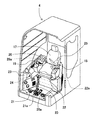
- FIG. 2 is a perspective view showing the inside of the cab 4.
- a driver's seat 17 on which an operator is seated, operating levers 18 and 19 for operating the front working machine 3 and the swinging operation of the upper swing body 2, and the lower traveling body 1 are provided.
- Travel levers 20 and 21 for operating the left and right travel hydraulic motors 1a and 1b, and left and right travel pedals 20a and 21a that can be operated in conjunction with the travel levers 20 and 21 are provided.
- a buzzer 24 (notifying device) that can notify the operator of various alarms by outputting sound or voice is arranged.
- an unlocked position specifically, a descending position that prevents the operator from getting in and out
- a locked position specifically, Is provided with a gate lock lever 22 that is operated to a position where the operator can get in and out of the vehicle.
- the gate lock lever 22 is provided with a gate lock switch 22a that is closed when the gate lock lever 22 is in the unlocked position (down position) and open when the gate lock lever 22 is in the locked position (up position).
- the driver's seat 17 is provided with a seat belt 25 and a buckle 26 for fixing the seat belt 25.
- the buckle 26 is provided with a seat belt switch 26a for detecting the wearing of the seat belt 25.
- FIG. 3 is a configuration diagram of an alarm system mounted on the hydraulic excavator 100.
- the alarm system 200 includes a seat belt switch 26a, a gate lock switch 22a, cameras 14 to 16, a controller 60, and a buzzer 24.
- the controller 60 has a seat belt wearing determination unit 61, a moving body determination unit 62, and a buzzer output unit 63.
- the seat belt wearing determination unit 61 determines whether or not the seat belt is worn, based on the input from the seat belt switch 26a, and unlocks the gate lock lever 22 based on the input from the gate lock switch 22a. It is determined whether it is in the position.
- the moving body determination unit 62 determines the presence or absence of a moving body based on the images taken by the cameras 14 to 16.
- the buzzer output unit 63 outputs a command signal to the buzzer 24 based on the determination results of the seat belt wearing determination unit 61 and the moving body determination unit 62.
- FIG. 4 is a flowchart showing the processing of the seatbelt wearing determination unit 61.
- the seatbelt wearing determination unit 61 first determines in step S101 whether the seatbelt 25 is worn (the seatbelt switch 26a is ON).
- step S101 the seat belt 25 is worn
- the seat belt warning flag is turned OFF in step S104, and the process ends.
- step S101 the seat belt 25 is not worn
- step S102 it is determined in step S102 whether the gate lock lever 22 is in the unlocked position (gate lock switch 22a is OFF).
- step S102 If YES is determined in step S102 (the gate lock lever 22 is in the unlocked position), the seat belt warning flag is turned ON in step S103, and the process ends.
- step S102 If NO is determined in step S102 (the gate lock lever 22 is in the lock position), the seat belt warning flag is turned off in step S104, and the process ends.
- FIG. 5 is a flowchart showing the processing of the mobile unit determination unit 62.
- step S201 the moving body determination unit 62 determines the presence or absence of a moving body in the peripheral images input from the cameras 14 to 16.
- step S201 If YES (there is a moving object) is determined in step S201, the moving object detection warning flag is turned ON in step S202, and the process ends.
- step S201 If NO (no moving body) is determined in step S201, the moving body detection warning flag is turned OFF in step S203, and the process is ended.
- FIG. 6 is a flowchart showing the processing of the buzzer output unit 63.
- step S301 the buzzer output unit 63 determines whether or not the seatbelt warning flag input from the seatbelt wearing determination unit 61 is ON.
- step S301 If YES is determined in step S301 (seat belt warning flag is ON), a seat belt warning (first warning) is output via the buzzer 24, and the process ends.
- step S301 If NO is determined in step S301 (the seat belt warning flag is OFF), it is determined in step S303 whether the moving body detection warning flag input from the moving body determination unit 62 is ON.
- step S303 moving body detection alarm flag is ON
- a moving body detection alarm (second alarm) is output via the buzzer 24, and the process ends.
- step S303 If it is determined NO in step S303 (the moving body detection warning flag is OFF), the output of the buzzer 24 is turned OFF, and the process ends.
- the lower traveling structure 1, the upper revolving structure 2 provided above the lower traveling structure 1, the driver's cab 4 provided in front of the upper revolving structure 2, and the surroundings of the upper revolving structure 2 are monitored.
- the cameras 14 to 16, the notification device 24 provided in the driver's cab 4, and the presence or absence of a moving body are detected from the images of the cameras 14 to 16, and when the moving body is detected, the notification device 24 is used.
- the controller 60 When the moving body is detected and the seatbelt detection device 26a detects the wearing of the seat belt 25, the first warning is output via the notification device 24, and the moving body is detected. If the seatbelt detection device 26a detects that the seatbelt 25 is not worn, a second alarm is output via the notification device 24, the moving body is detected, and the seatbelt detection device 26a is detected. When it is detected that the seat belt 25 is not worn, the second alarm is output via the notification device 24 with priority over the first alarm.
- the second alarm (the seatbelt 25 is not worn is detected) via the notification device 24.
- the alarm for notifying is output with priority over the first alarm (alarm for notifying the detection of the moving body).
- the controller 60 does not output the first alarm via the notification device 24 while outputting the second alarm via the notification device 24.
- the alarm first alarm
- the second alarm only the alarm indicating that the seat belt 25 is not mounted is output.
- the operator can surely recognize the alarm notifying that the seat belt 25 is not worn.
- the alarm (first alarm) indicating the presence of the moving body is not output while the alarm (second alarm) indicating that the seat belt 25 is not worn is output.
- the method of prioritizing the second alarm over the first alarm is not limited to this, and a method of lowering the volume of the first alarm while the second alarm is being output may be adopted.
- the hydraulic excavator 100 according to the second embodiment of the present invention will be described focusing on the differences from the first embodiment.
- FIG. 7 is a diagram showing the configuration of the alarm system in this embodiment.
- the difference from the first embodiment is that instead of a single buzzer 24, a seat belt buzzer 27 for notifying that the seat belt 25 is not worn and a moving body detection are notified.
- the mobile object detection buzzer 28 is provided.
- the buzzer output unit 63 in this embodiment outputs a seat belt alarm via the seat belt buzzer 27 in step S302 shown in FIG. 6, and outputs a moving body detection alarm via the moving body detection buzzer 28 in step S304. To do.
- the first notification device 28 and the second notification device 27 provided independently of the first notification device 28 are provided, and the controller 60 is configured to operate via the first notification device 28.
- the first alarm is output and the second alarm is output via the second notification device 27.
- the hydraulic shovel 100 according to this embodiment configured as described above can also achieve the same effect as that of the first embodiment.
- the seat belt buzzer 27 for notifying that the seat belt 25 is not worn and the moving body detecting buzzer 28 for notifying the moving body detection are independently provided, so that a first alarm for notifying the moving body detection, Since the type (tone color, sound volume, pattern) of the second alarm notifying that the seat belt 25 is not worn can be flexibly changed, the distinctiveness of each alarm can be improved.
- the present invention is not limited to the above-described embodiments and includes various modifications.
- the notification device is configured by the buzzer in the above-described embodiments
- the present invention is not limited to this, and may be configured by a monitor, a lamp, or the like.
- the above-described embodiments have been described in detail in order to explain the present invention in an easy-to-understand manner, and are not necessarily limited to those having all the configurations described. Further, it is possible to add a part of the configuration of another embodiment to the configuration of a certain embodiment, delete a part of the configuration of a certain embodiment, or replace it with a part of another embodiment. It is possible.
- Monitor 24 ... Buzzer (informing device), 25 ... Seat belt, 26 ... Buckle, 26a ... Seat belt switch (seat belt detection) Device), 27 ... Buzzer for seat belt (second alarm device), 28 ... Buzzer for moving body detection (first alarm device), 6 ... controller, 61 ... seat belt determining unit, 62 ... mobile judging unit, 63 ... buzzer output unit, 100 ... hydraulic excavator, 200 ... alarm system.
Landscapes
- Engineering & Computer Science (AREA)
- Mining & Mineral Resources (AREA)
- Civil Engineering (AREA)
- General Engineering & Computer Science (AREA)
- Structural Engineering (AREA)
- Mechanical Engineering (AREA)
- Physics & Mathematics (AREA)
- Acoustics & Sound (AREA)
- Automation & Control Theory (AREA)
- Component Parts Of Construction Machinery (AREA)
Abstract
Cette invention concerne une pelleteuse hydraulique ainsi conçue que même lorsqu'elle fonctionne dans une situation avec des corps mobiles présents autour du corps de pelleteuse, l'opérateur peut reconnaître de manière fiable des avertissements indiquant que la ceinture de sécurité est détachée. Plus particulièrement l'invention concerne un dispositif de commande qui délivre un premier avertissement par l'intermédiaire d'un système de notification dans le cas où des corps mobiles ont été détectés et qu'un dispositif de détection de ceinture de sécurité a détecté que la ceinture de sécurité est attachée, délivre un second signal d'avertissement par l'intermédiaire du dispositif de notification dans le cas où des corps mobiles n'ont pas été détectés et que le dispositif de détection de ceinture de sécurité a détecté que la ceinture de sécurité n'est pas attachée, et délivre, avec une priorité plus élevée que le premier avertissement, le second avertissement par l'intermédiaire du dispositif de notification dans le cas où des corps mobiles ont été détectés et que le dispositif de détection de ceinture de sécurité a détecté que la ceinture de sécurité n'est pas attachée.
Priority Applications (5)
| Application Number | Priority Date | Filing Date | Title |
|---|---|---|---|
| KR1020237032910A KR20230145209A (ko) | 2018-10-15 | 2019-10-11 | 유압 셔블 |
| EP19873734.8A EP3832035B1 (fr) | 2018-10-15 | 2019-10-11 | Pelleteuse hydraulique |
| US17/273,803 US11739503B2 (en) | 2018-10-15 | 2019-10-11 | Hydraulic excavator |
| KR1020217004781A KR20210032483A (ko) | 2018-10-15 | 2019-10-11 | 유압 셔블 |
| CN201980054400.1A CN112585323A (zh) | 2018-10-15 | 2019-10-11 | 液压挖掘机 |
Applications Claiming Priority (2)
| Application Number | Priority Date | Filing Date | Title |
|---|---|---|---|
| JP2018-194647 | 2018-10-15 | ||
| JP2018194647A JP2020063566A (ja) | 2018-10-15 | 2018-10-15 | 油圧ショベル |
Publications (1)
| Publication Number | Publication Date |
|---|---|
| WO2020080293A1 true WO2020080293A1 (fr) | 2020-04-23 |
Family
ID=70284622
Family Applications (1)
| Application Number | Title | Priority Date | Filing Date |
|---|---|---|---|
| PCT/JP2019/040239 WO2020080293A1 (fr) | 2018-10-15 | 2019-10-11 | Pelleteuse hydraulique |
Country Status (6)
| Country | Link |
|---|---|
| US (1) | US11739503B2 (fr) |
| EP (1) | EP3832035B1 (fr) |
| JP (2) | JP2020063566A (fr) |
| KR (2) | KR20210032483A (fr) |
| CN (1) | CN112585323A (fr) |
| WO (1) | WO2020080293A1 (fr) |
Families Citing this family (2)
| Publication number | Priority date | Publication date | Assignee | Title |
|---|---|---|---|---|
| JP7283070B2 (ja) * | 2018-12-19 | 2023-05-30 | コベルコ建機株式会社 | 作業機械用周辺監視装置 |
| US11521397B2 (en) * | 2020-09-08 | 2022-12-06 | Caterpillar Inc. | Object tracking for work machines |
Citations (6)
| Publication number | Priority date | Publication date | Assignee | Title |
|---|---|---|---|---|
| JP2013159193A (ja) * | 2012-02-03 | 2013-08-19 | Nippon Seiki Co Ltd | シートベルトの装着情報報知装置 |
| JP2014181509A (ja) * | 2013-03-19 | 2014-09-29 | Sumitomo Heavy Ind Ltd | 作業機械用周辺監視装置 |
| WO2015025439A1 (fr) * | 2013-11-19 | 2015-02-26 | 株式会社小松製作所 | Dispositif d'affichage pour véhicule utilitaire et son procédé d'affichage |
| JP2017145626A (ja) | 2016-02-17 | 2017-08-24 | 日立建機株式会社 | 建設機械の安全装置 |
| JP2018111981A (ja) | 2017-01-11 | 2018-07-19 | 住友建機株式会社 | 作業機械用周辺監視システム |
| WO2018155567A1 (fr) * | 2017-02-22 | 2018-08-30 | 住友建機株式会社 | Excavatrice |
Family Cites Families (9)
| Publication number | Priority date | Publication date | Assignee | Title |
|---|---|---|---|---|
| JPS57118490U (fr) * | 1981-01-19 | 1982-07-22 | ||
| JP2002229642A (ja) * | 2001-02-07 | 2002-08-16 | Seto Denshi Kogyo Kk | 生産ラインや生産設備などの稼働管理システム |
| JP3827964B2 (ja) * | 2001-03-28 | 2006-09-27 | 株式会社クボタ | バックホウ |
| JP3821789B2 (ja) * | 2003-03-12 | 2006-09-13 | 本田技研工業株式会社 | シートベルト未装着警報装置 |
| KR101797261B1 (ko) * | 2010-06-18 | 2017-11-13 | 히다찌 겐끼 가부시키가이샤 | 작업 기계의 주위 감시 장치 |
| JP6545430B2 (ja) | 2013-03-19 | 2019-07-17 | 住友重機械工業株式会社 | ショベル |
| CN103324158A (zh) * | 2013-05-14 | 2013-09-25 | 浙江大学 | 一种带人脸检测的工程机械机载视频监控系统 |
| CN108026714A (zh) * | 2015-11-30 | 2018-05-11 | 住友重机械工业株式会社 | 施工机械用周边监视系统 |
| CN111953942B (zh) * | 2015-11-30 | 2022-07-12 | 住友重机械工业株式会社 | 施工机械用周边监视系统 |
-
2018
- 2018-10-15 JP JP2018194647A patent/JP2020063566A/ja active Pending
-
2019
- 2019-10-11 EP EP19873734.8A patent/EP3832035B1/fr active Active
- 2019-10-11 CN CN201980054400.1A patent/CN112585323A/zh active Pending
- 2019-10-11 KR KR1020217004781A patent/KR20210032483A/ko not_active IP Right Cessation
- 2019-10-11 KR KR1020237032910A patent/KR20230145209A/ko active Application Filing
- 2019-10-11 WO PCT/JP2019/040239 patent/WO2020080293A1/fr unknown
- 2019-10-11 US US17/273,803 patent/US11739503B2/en active Active
-
2023
- 2023-02-22 JP JP2023025716A patent/JP7478275B2/ja active Active
Patent Citations (6)
| Publication number | Priority date | Publication date | Assignee | Title |
|---|---|---|---|---|
| JP2013159193A (ja) * | 2012-02-03 | 2013-08-19 | Nippon Seiki Co Ltd | シートベルトの装着情報報知装置 |
| JP2014181509A (ja) * | 2013-03-19 | 2014-09-29 | Sumitomo Heavy Ind Ltd | 作業機械用周辺監視装置 |
| WO2015025439A1 (fr) * | 2013-11-19 | 2015-02-26 | 株式会社小松製作所 | Dispositif d'affichage pour véhicule utilitaire et son procédé d'affichage |
| JP2017145626A (ja) | 2016-02-17 | 2017-08-24 | 日立建機株式会社 | 建設機械の安全装置 |
| JP2018111981A (ja) | 2017-01-11 | 2018-07-19 | 住友建機株式会社 | 作業機械用周辺監視システム |
| WO2018155567A1 (fr) * | 2017-02-22 | 2018-08-30 | 住友建機株式会社 | Excavatrice |
Also Published As
| Publication number | Publication date |
|---|---|
| US20210310218A1 (en) | 2021-10-07 |
| JP2023054217A (ja) | 2023-04-13 |
| JP2020063566A (ja) | 2020-04-23 |
| JP7478275B2 (ja) | 2024-05-02 |
| EP3832035A4 (fr) | 2022-06-01 |
| US11739503B2 (en) | 2023-08-29 |
| EP3832035A1 (fr) | 2021-06-09 |
| EP3832035B1 (fr) | 2024-01-17 |
| KR20230145209A (ko) | 2023-10-17 |
| CN112585323A (zh) | 2021-03-30 |
| KR20210032483A (ko) | 2021-03-24 |
Similar Documents
| Publication | Publication Date | Title |
|---|---|---|
| KR102646808B1 (ko) | 작업 기계 및 주위 감시 시스템 | |
| JP7478275B2 (ja) | 油圧ショベル | |
| WO2017141500A1 (fr) | Dispositif de sécurité pour engin de chantier | |
| WO2021010249A1 (fr) | Engin de chantier et système de commande d'un engin de chantier | |
| JP7258613B2 (ja) | 作業機械 | |
| WO2021010250A1 (fr) | Engin de chantier | |
| EP3522133B1 (fr) | Système et procédé de surveillance de proximité de véhicule de chantier | |
| JP4597914B2 (ja) | 作業機械 | |
| KR20230085910A (ko) | 건설 기계 | |
| JP2018111981A (ja) | 作業機械用周辺監視システム | |
| JP2024028630A (ja) | 作業車両 | |
| JP7112935B2 (ja) | 作業機械 | |
| KR102494287B1 (ko) | 작업 기계 | |
| JP2017061283A (ja) | 作業車両の周囲監視装置 | |
| WO2021085448A1 (fr) | Machine de construction | |
| US20230114366A1 (en) | Work machine periphery monitoring system, work machine, and work machine periphery monitoring method | |
| JP2010043419A (ja) | 自走式作業機械の表示装置 | |
| JP7349880B2 (ja) | 作業機械の周辺監視システム、作業機械、及び作業機械の周辺監視方法 | |
| JP2014009555A (ja) | 建設機械 | |
| KR20230085909A (ko) | 작업 차량 | |
| JP2024052153A (ja) | 建設機械 | |
| JP2001171981A (ja) | 相互連携車両の走行安全装置 |
Legal Events
| Date | Code | Title | Description |
|---|---|---|---|
| 121 | Ep: the epo has been informed by wipo that ep was designated in this application |
Ref document number: 19873734 Country of ref document: EP Kind code of ref document: A1 |
|
| ENP | Entry into the national phase |
Ref document number: 20217004781 Country of ref document: KR Kind code of ref document: A |
|
| ENP | Entry into the national phase |
Ref document number: 2019873734 Country of ref document: EP Effective date: 20210304 |
|
| NENP | Non-entry into the national phase |
Ref country code: DE |