WO2020080293A1 - Hydraulic excavator - Google Patents
Hydraulic excavator Download PDFInfo
- Publication number
- WO2020080293A1 WO2020080293A1 PCT/JP2019/040239 JP2019040239W WO2020080293A1 WO 2020080293 A1 WO2020080293 A1 WO 2020080293A1 JP 2019040239 W JP2019040239 W JP 2019040239W WO 2020080293 A1 WO2020080293 A1 WO 2020080293A1
- Authority
- WO
- WIPO (PCT)
- Prior art keywords
- alarm
- seat belt
- notification device
- moving body
- detected
- Prior art date
Links
- 238000001514 detection method Methods 0.000 claims abstract description 37
- 238000012544 monitoring process Methods 0.000 claims description 5
- 238000000034 method Methods 0.000 description 12
- 238000010276 construction Methods 0.000 description 7
- 230000002093 peripheral effect Effects 0.000 description 3
- 238000010586 diagram Methods 0.000 description 2
- 230000000694 effects Effects 0.000 description 1
- 238000012986 modification Methods 0.000 description 1
- 230000004048 modification Effects 0.000 description 1
- 230000000007 visual effect Effects 0.000 description 1
Images


Classifications
-
- E—FIXED CONSTRUCTIONS
- E02—HYDRAULIC ENGINEERING; FOUNDATIONS; SOIL SHIFTING
- E02F—DREDGING; SOIL-SHIFTING
- E02F9/00—Component parts of dredgers or soil-shifting machines, not restricted to one of the kinds covered by groups E02F3/00 - E02F7/00
- E02F9/26—Indicating devices
-
- B—PERFORMING OPERATIONS; TRANSPORTING
- B60—VEHICLES IN GENERAL
- B60Q—ARRANGEMENT OF SIGNALLING OR LIGHTING DEVICES, THE MOUNTING OR SUPPORTING THEREOF OR CIRCUITS THEREFOR, FOR VEHICLES IN GENERAL
- B60Q5/00—Arrangement or adaptation of acoustic signal devices
- B60Q5/005—Arrangement or adaptation of acoustic signal devices automatically actuated
-
- B—PERFORMING OPERATIONS; TRANSPORTING
- B60—VEHICLES IN GENERAL
- B60R—VEHICLES, VEHICLE FITTINGS, OR VEHICLE PARTS, NOT OTHERWISE PROVIDED FOR
- B60R22/00—Safety belts or body harnesses in vehicles
- B60R22/48—Control systems, alarms, or interlock systems, for the correct application of the belt or harness
-
- E—FIXED CONSTRUCTIONS
- E02—HYDRAULIC ENGINEERING; FOUNDATIONS; SOIL SHIFTING
- E02F—DREDGING; SOIL-SHIFTING
- E02F9/00—Component parts of dredgers or soil-shifting machines, not restricted to one of the kinds covered by groups E02F3/00 - E02F7/00
- E02F9/08—Superstructures; Supports for superstructures
- E02F9/10—Supports for movable superstructures mounted on travelling or walking gears or on other superstructures
- E02F9/12—Slewing or traversing gears
- E02F9/121—Turntables, i.e. structure rotatable about 360°
- E02F9/123—Drives or control devices specially adapted therefor
-
- E—FIXED CONSTRUCTIONS
- E02—HYDRAULIC ENGINEERING; FOUNDATIONS; SOIL SHIFTING
- E02F—DREDGING; SOIL-SHIFTING
- E02F9/00—Component parts of dredgers or soil-shifting machines, not restricted to one of the kinds covered by groups E02F3/00 - E02F7/00
- E02F9/16—Cabins, platforms, or the like, for drivers
-
- E—FIXED CONSTRUCTIONS
- E02—HYDRAULIC ENGINEERING; FOUNDATIONS; SOIL SHIFTING
- E02F—DREDGING; SOIL-SHIFTING
- E02F9/00—Component parts of dredgers or soil-shifting machines, not restricted to one of the kinds covered by groups E02F3/00 - E02F7/00
- E02F9/24—Safety devices, e.g. for preventing overload
-
- E—FIXED CONSTRUCTIONS
- E02—HYDRAULIC ENGINEERING; FOUNDATIONS; SOIL SHIFTING
- E02F—DREDGING; SOIL-SHIFTING
- E02F9/00—Component parts of dredgers or soil-shifting machines, not restricted to one of the kinds covered by groups E02F3/00 - E02F7/00
- E02F9/26—Indicating devices
- E02F9/261—Surveying the work-site to be treated
-
- E—FIXED CONSTRUCTIONS
- E02—HYDRAULIC ENGINEERING; FOUNDATIONS; SOIL SHIFTING
- E02F—DREDGING; SOIL-SHIFTING
- E02F9/00—Component parts of dredgers or soil-shifting machines, not restricted to one of the kinds covered by groups E02F3/00 - E02F7/00
- E02F9/26—Indicating devices
- E02F9/264—Sensors and their calibration for indicating the position of the work tool
-
- B—PERFORMING OPERATIONS; TRANSPORTING
- B60—VEHICLES IN GENERAL
- B60Y—INDEXING SCHEME RELATING TO ASPECTS CROSS-CUTTING VEHICLE TECHNOLOGY
- B60Y2200/00—Type of vehicle
- B60Y2200/40—Special vehicles
- B60Y2200/41—Construction vehicles, e.g. graders, excavators
- B60Y2200/412—Excavators
-
- E—FIXED CONSTRUCTIONS
- E02—HYDRAULIC ENGINEERING; FOUNDATIONS; SOIL SHIFTING
- E02F—DREDGING; SOIL-SHIFTING
- E02F9/00—Component parts of dredgers or soil-shifting machines, not restricted to one of the kinds covered by groups E02F3/00 - E02F7/00
- E02F9/16—Cabins, platforms, or the like, for drivers
- E02F9/163—Structures to protect drivers, e.g. cabins, doors for cabins; Falling object protection structure [FOPS]; Roll over protection structure [ROPS]
Definitions
- the present invention relates to a hydraulic excavator.
- Patent Document 1 is a prior art document disclosing a safety device for a construction machine that can alert an operator according to the state of the construction machine.
- a state information acquisition unit that acquires state information regarding the state of a construction machine, a seat belt detection unit that detects whether or not a seat belt is worn by an operator, and the seat belt is worn by the operator.
- a safety device for a construction machine comprising: a control unit that controls a warning unit to issue a warning based on the state information, wherein the state information is an operation lever of the construction machine.
- the control unit includes information about an operation position of the gate lock lever operated to a lock position for invalidating the command and an unlock position for validating the command of the operation lever.
- a safety device for a construction machine is described, which is characterized in that the warning part is controlled so as to issue a warning in the unlocked position. ..
- Patent Document 2 is disclosed as a prior art document disclosing a work machine peripheral monitoring system capable of suppressing the annoyance of an operator while ensuring the effectiveness of an alarm based on the detection of a predetermined object to be monitored. is there.
- Patent Literature 2 discloses an object detection unit that detects a predetermined object existing within a predetermined range around a work machine, and an alarm unit that issues a sound alarm when the object detection unit detects the object.
- the alarm unit stops the alarm by the sound when a predetermined condition is satisfied, and outputs the alarm by the sound.
- a perimeter monitoring system for work machines is described, which issues a warning by light after stopping.
- the present invention has been made in view of the above problems, and an object thereof is to reliably provide an alarm notifying that the operator has not worn the seat belt even when performing work in a situation where a moving body exists around the machine body. It is to provide a hydraulic excavator that can be recognized.
- the present invention provides a lower traveling structure, an upper revolving structure provided above the lower traveling structure, a driver's cab provided in front of the upper revolving structure, and the upper revolving structure.
- a camera that monitors the surroundings of the vehicle, a notification device, a controller that detects the presence or absence of a moving object from the image of the camera, and outputs an alarm via the notification device when the moving object is detected, and the driver's cab
- a hydraulic excavator including a seat belt provided in a vehicle, and a seat belt detection device that detects whether or not the seat belt is worn, in the controller, the controller detects the moving body and the seat belt detection device.
- the first alarm is output via the notification device, the moving body is not detected, and the seat belt detection device
- a second alarm is output via the notification device, the moving body is detected, and the seat belt detector detects that the seat belt is not worn.
- the second alarm is output via the notification device with priority over the first alarm.
- the second alarm (alarm notifying that the seatbelt is not worn) is issued via the alarm device. Is output with priority over the first alarm (alarm notifying the detection of a moving object).
- the operator can surely recognize the alarm notifying that the seat belt is not worn even when working under the condition that the moving body exists around the machine body.
- FIG. 4 It is a side view which shows roughly the external appearance of the hydraulic excavator which concerns on the 1st Example of this invention. It is a perspective view which shows the inside of the operator's cab shown in FIG. It is a figure which shows the structure of the alarm system mounted in the hydraulic excavator shown in FIG. 4 is a flowchart showing a process of a seatbelt wearing determination unit of the controller shown in FIG. 4 is a flowchart showing processing of a moving body determination unit of the controller shown in FIG. 3. 4 is a flowchart showing a process of a buzzer output unit of the controller shown in FIG. 3. It is a figure which shows the structure of the alarm system in the 2nd Example of this invention.
- FIG. 1 is a side view schematically showing the external appearance of a hydraulic excavator according to the first embodiment of the present invention.
- a hydraulic excavator 100 is provided with a crawler-type lower traveling body 1, an upper revolving body 2 that is provided so as to be rotatable with respect to the lower traveling body 1, and is provided so as to be able to move up and down in front of the upper revolving body 2. And a front working machine 3.
- the front working machine 3 is configured by connecting a plurality of driven members (boom 3a, arm 3b, and bucket 3c) that rotate in the vertical direction, respectively.
- the base end of the boom 3a is rotatably supported by the front part of the upper swing body 2.
- one end of an arm 3b is rotatably connected to the tip of the boom 3a
- a bucket 3c is rotatably connected to the other end (tip) of the arm 3b.
- the boom 3a, the arm 3b, and the bucket 3c are driven by a boom cylinder 3d, an arm cylinder 3e, and a bucket cylinder 3f, which are hydraulic actuators, respectively.
- the lower traveling body 1 is a hydraulic actuator that drives the pair of crawlers 1e (1f) wound around the pair of left and right crawler frames 1c (1d) and the crawler 1e (1f) via a reduction mechanism (not shown) or the like.
- a reduction mechanism not shown
- traveling hydraulic motor 1a (1b). Note that, in FIG. 1, for each configuration of the lower traveling body 1, only one of a pair of left and right configurations is illustrated and assigned a reference numeral, and for the other configuration, only reference numerals in parentheses are shown in the drawing. Illustration is omitted.
- the upper swing body 2 is configured by arranging each member on a swing frame 2a serving as a base, and the swing frame 2a swings with respect to the lower traveling body 1 by a swing hydraulic motor (not shown) that is a hydraulic actuator. By being driven, the upper swing body 2 can swing with respect to the lower traveling body 1.
- An operator's cab 4 for an operator to operate the hydraulic excavator 100 is arranged on the revolving frame 2a of the upper revolving structure 2, and an engine as a prime mover, a hydraulic pump driven by the engine, and a pilot are arranged.
- a hydraulic circuit system for driving the pump, each hydraulic actuator (travel hydraulic motors 1a and 1b, swing hydraulic motor (not shown), boom cylinder 3d, arm cylinder 3e, bucket cylinder 3f), a controller 60 (see FIG. 6) described later. (As shown in) is installed.
- Cameras 14 to 16 for monitoring the surroundings of the vehicle body are mounted on the left and right of the upper part of the upper swing body 2 and on the rear side.
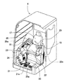
- FIG. 2 is a perspective view showing the inside of the cab 4.
- a driver's seat 17 on which an operator is seated, operating levers 18 and 19 for operating the front working machine 3 and the swinging operation of the upper swing body 2, and the lower traveling body 1 are provided.
- Travel levers 20 and 21 for operating the left and right travel hydraulic motors 1a and 1b, and left and right travel pedals 20a and 21a that can be operated in conjunction with the travel levers 20 and 21 are provided.
- a buzzer 24 (notifying device) that can notify the operator of various alarms by outputting sound or voice is arranged.
- an unlocked position specifically, a descending position that prevents the operator from getting in and out
- a locked position specifically, Is provided with a gate lock lever 22 that is operated to a position where the operator can get in and out of the vehicle.
- the gate lock lever 22 is provided with a gate lock switch 22a that is closed when the gate lock lever 22 is in the unlocked position (down position) and open when the gate lock lever 22 is in the locked position (up position).
- the driver's seat 17 is provided with a seat belt 25 and a buckle 26 for fixing the seat belt 25.
- the buckle 26 is provided with a seat belt switch 26a for detecting the wearing of the seat belt 25.
- FIG. 3 is a configuration diagram of an alarm system mounted on the hydraulic excavator 100.
- the alarm system 200 includes a seat belt switch 26a, a gate lock switch 22a, cameras 14 to 16, a controller 60, and a buzzer 24.
- the controller 60 has a seat belt wearing determination unit 61, a moving body determination unit 62, and a buzzer output unit 63.
- the seat belt wearing determination unit 61 determines whether or not the seat belt is worn, based on the input from the seat belt switch 26a, and unlocks the gate lock lever 22 based on the input from the gate lock switch 22a. It is determined whether it is in the position.
- the moving body determination unit 62 determines the presence or absence of a moving body based on the images taken by the cameras 14 to 16.
- the buzzer output unit 63 outputs a command signal to the buzzer 24 based on the determination results of the seat belt wearing determination unit 61 and the moving body determination unit 62.
- FIG. 4 is a flowchart showing the processing of the seatbelt wearing determination unit 61.
- the seatbelt wearing determination unit 61 first determines in step S101 whether the seatbelt 25 is worn (the seatbelt switch 26a is ON).
- step S101 the seat belt 25 is worn
- the seat belt warning flag is turned OFF in step S104, and the process ends.
- step S101 the seat belt 25 is not worn
- step S102 it is determined in step S102 whether the gate lock lever 22 is in the unlocked position (gate lock switch 22a is OFF).
- step S102 If YES is determined in step S102 (the gate lock lever 22 is in the unlocked position), the seat belt warning flag is turned ON in step S103, and the process ends.
- step S102 If NO is determined in step S102 (the gate lock lever 22 is in the lock position), the seat belt warning flag is turned off in step S104, and the process ends.
- FIG. 5 is a flowchart showing the processing of the mobile unit determination unit 62.
- step S201 the moving body determination unit 62 determines the presence or absence of a moving body in the peripheral images input from the cameras 14 to 16.
- step S201 If YES (there is a moving object) is determined in step S201, the moving object detection warning flag is turned ON in step S202, and the process ends.
- step S201 If NO (no moving body) is determined in step S201, the moving body detection warning flag is turned OFF in step S203, and the process is ended.
- FIG. 6 is a flowchart showing the processing of the buzzer output unit 63.
- step S301 the buzzer output unit 63 determines whether or not the seatbelt warning flag input from the seatbelt wearing determination unit 61 is ON.
- step S301 If YES is determined in step S301 (seat belt warning flag is ON), a seat belt warning (first warning) is output via the buzzer 24, and the process ends.
- step S301 If NO is determined in step S301 (the seat belt warning flag is OFF), it is determined in step S303 whether the moving body detection warning flag input from the moving body determination unit 62 is ON.
- step S303 moving body detection alarm flag is ON
- a moving body detection alarm (second alarm) is output via the buzzer 24, and the process ends.
- step S303 If it is determined NO in step S303 (the moving body detection warning flag is OFF), the output of the buzzer 24 is turned OFF, and the process ends.
- the lower traveling structure 1, the upper revolving structure 2 provided above the lower traveling structure 1, the driver's cab 4 provided in front of the upper revolving structure 2, and the surroundings of the upper revolving structure 2 are monitored.
- the cameras 14 to 16, the notification device 24 provided in the driver's cab 4, and the presence or absence of a moving body are detected from the images of the cameras 14 to 16, and when the moving body is detected, the notification device 24 is used.
- the controller 60 When the moving body is detected and the seatbelt detection device 26a detects the wearing of the seat belt 25, the first warning is output via the notification device 24, and the moving body is detected. If the seatbelt detection device 26a detects that the seatbelt 25 is not worn, a second alarm is output via the notification device 24, the moving body is detected, and the seatbelt detection device 26a is detected. When it is detected that the seat belt 25 is not worn, the second alarm is output via the notification device 24 with priority over the first alarm.
- the second alarm (the seatbelt 25 is not worn is detected) via the notification device 24.
- the alarm for notifying is output with priority over the first alarm (alarm for notifying the detection of the moving body).
- the controller 60 does not output the first alarm via the notification device 24 while outputting the second alarm via the notification device 24.
- the alarm first alarm
- the second alarm only the alarm indicating that the seat belt 25 is not mounted is output.
- the operator can surely recognize the alarm notifying that the seat belt 25 is not worn.
- the alarm (first alarm) indicating the presence of the moving body is not output while the alarm (second alarm) indicating that the seat belt 25 is not worn is output.
- the method of prioritizing the second alarm over the first alarm is not limited to this, and a method of lowering the volume of the first alarm while the second alarm is being output may be adopted.
- the hydraulic excavator 100 according to the second embodiment of the present invention will be described focusing on the differences from the first embodiment.
- FIG. 7 is a diagram showing the configuration of the alarm system in this embodiment.
- the difference from the first embodiment is that instead of a single buzzer 24, a seat belt buzzer 27 for notifying that the seat belt 25 is not worn and a moving body detection are notified.
- the mobile object detection buzzer 28 is provided.
- the buzzer output unit 63 in this embodiment outputs a seat belt alarm via the seat belt buzzer 27 in step S302 shown in FIG. 6, and outputs a moving body detection alarm via the moving body detection buzzer 28 in step S304. To do.
- the first notification device 28 and the second notification device 27 provided independently of the first notification device 28 are provided, and the controller 60 is configured to operate via the first notification device 28.
- the first alarm is output and the second alarm is output via the second notification device 27.
- the hydraulic shovel 100 according to this embodiment configured as described above can also achieve the same effect as that of the first embodiment.
- the seat belt buzzer 27 for notifying that the seat belt 25 is not worn and the moving body detecting buzzer 28 for notifying the moving body detection are independently provided, so that a first alarm for notifying the moving body detection, Since the type (tone color, sound volume, pattern) of the second alarm notifying that the seat belt 25 is not worn can be flexibly changed, the distinctiveness of each alarm can be improved.
- the present invention is not limited to the above-described embodiments and includes various modifications.
- the notification device is configured by the buzzer in the above-described embodiments
- the present invention is not limited to this, and may be configured by a monitor, a lamp, or the like.
- the above-described embodiments have been described in detail in order to explain the present invention in an easy-to-understand manner, and are not necessarily limited to those having all the configurations described. Further, it is possible to add a part of the configuration of another embodiment to the configuration of a certain embodiment, delete a part of the configuration of a certain embodiment, or replace it with a part of another embodiment. It is possible.
- Monitor 24 ... Buzzer (informing device), 25 ... Seat belt, 26 ... Buckle, 26a ... Seat belt switch (seat belt detection) Device), 27 ... Buzzer for seat belt (second alarm device), 28 ... Buzzer for moving body detection (first alarm device), 6 ... controller, 61 ... seat belt determining unit, 62 ... mobile judging unit, 63 ... buzzer output unit, 100 ... hydraulic excavator, 200 ... alarm system.
Abstract
A hydraulic excavator is provided in which, even when operating in a situation with moving bodies present around the excavator body, the operator can reliably recognize warnings advising that the seatbelt is unfastened. This controller outputs a first warning through a notification system in the case that moving bodies have been detected and a seatbelt detection device has detected that the seatbelt is fastened, outputs a second warning signal through the notification device in the case that moving bodies have not been detected and the seatbelt detection device has detected that the seatbelt is unfastened, and outputs, with higher priority than the first warning, the second warning through the notification device in the case that moving bodies have been detected and the seatbelt detection device has detected that the seatbelt is unfastened.
Description
本発明は、油圧ショベルに関する。
The present invention relates to a hydraulic excavator.
建設機械の状態に応じて、オペレータに注意を促すことができる建設機械の安全装置を開示する先行技術文献として特許文献1がある。
Patent Document 1 is a prior art document disclosing a safety device for a construction machine that can alert an operator according to the state of the construction machine.
特許文献1には、建設機械の状態に関する状態情報を取得する状態情報取得部と、シートベルトがオペレータに装着されているか否かを検出するシートベルト検出部と、前記シートベルトが前記オペレータに装着されていない場合に、前記状態情報に基づいて警告を行うように警告部を制御する制御部と、を備えた建設機械の安全装置であって、前記状態情報は、前記建設機械の操作レバーの指令を無効とするロック位置と、前記操作レバーの指令を有効とするロック解除位置とに操作されるゲートロックレバーの操作位置に関する情報を含み、前記制御部は、前記ゲートロックレバーの操作位置が前記ロック解除位置の場合に、警告を行うように前記警告部を制御することを特徴とする建設機械の安全装置が記載されている。
In Patent Document 1, a state information acquisition unit that acquires state information regarding the state of a construction machine, a seat belt detection unit that detects whether or not a seat belt is worn by an operator, and the seat belt is worn by the operator. If not, a safety device for a construction machine, comprising: a control unit that controls a warning unit to issue a warning based on the state information, wherein the state information is an operation lever of the construction machine. The control unit includes information about an operation position of the gate lock lever operated to a lock position for invalidating the command and an unlock position for validating the command of the operation lever. A safety device for a construction machine is described, which is characterized in that the warning part is controlled so as to issue a warning in the unlocked position. ‥
また、監視対象である所定の物体の検知に基づく警報の実効性を確保しつつ、オペレータの煩わしさを抑制することが可能な作業機械用周辺監視システムを開示する先行技術文献として特許文献2がある。
Further, Patent Document 2 is disclosed as a prior art document disclosing a work machine peripheral monitoring system capable of suppressing the annoyance of an operator while ensuring the effectiveness of an alarm based on the detection of a predetermined object to be monitored. is there.
特許文献2には、作業機械の周辺の所定範囲内に存在する所定の物体を検知する物体検知部と、前記物体検知部により前記物体が検知された場合、音による警報を行う警報部と、を備え、前記警報部は、前記物体検知部により前記物体が検知された状態が継続している場合、所定の条件が成立したときに、前記音による警報を停止すると共に、前記音による警報の停止後、光による警報を行う、作業機械用周辺監視システムが記載されている。
Patent Literature 2 discloses an object detection unit that detects a predetermined object existing within a predetermined range around a work machine, and an alarm unit that issues a sound alarm when the object detection unit detects the object. When the object detection unit continues to detect the object, the alarm unit stops the alarm by the sound when a predetermined condition is satisfied, and outputs the alarm by the sound. A perimeter monitoring system for work machines is described, which issues a warning by light after stopping.
特許文献1に記載の建設機械の安全装置と特許文献2に記載の作業機械用周辺監視システムとを油圧ショベルに搭載した場合、シートベルトの未装着と移動体の検知をオペレータに知らせることが可能になると考えられる。
When the safety device for a construction machine described in Patent Document 1 and the work machine peripheral monitoring system described in Patent Document 2 are mounted on a hydraulic excavator, it is possible to notify an operator of seat belt non-mounting and detection of a moving body. It is believed that
ところで、油圧ショベルの操作には、例えば機体をトレーラに搭載したり、狭い駐機場に駐機する等、機体を誘導する作業者等が機体の周辺にいる状況下で行われるものがある。このような状況下では、他の作業者等が移動体として検知されることにより、オペレータは移動体検知を知らせる警報が鳴り続ける状態で操作を行うこととなる。そのため、作業を開始する際にシートベルトを装着されていなかった場合、上述した油圧ショベルでは、移動体検知を知らせる警報とシートベルトの未装着を知らせる警報とが同時に発せられることにより、オペレータがシートベルトの未装着を知らせる警報を正しく認識できず、シートベルトを未装着のまま作業を継続してしまうおそれがある。
By the way, there are some operations of hydraulic excavators that are carried out under the condition where an operator or the like who guides the aircraft is around the aircraft, such as mounting the aircraft on a trailer or parking in a small parking lot. In such a situation, when another worker or the like is detected as a moving body, the operator operates in a state in which an alarm for detecting the moving body continues to sound. Therefore, if the seat belt is not worn at the time of starting the work, the hydraulic excavator described above issues an alarm notifying the detection of a moving body and an alarm notifying that the seat belt has not been worn at the same time, so that the operator can seat There is a risk that the alarm notifying that the seat belt has not been installed cannot be correctly recognized, and the work may continue without the seat belt installed.
本発明は、上記課題に鑑みてなされたものであり、その目的は、機体の周辺に移動体が存在する状況下で作業を行う場合でも、オペレータがシートベルトの未装着を知らせる警報を確実に認識することができる油圧ショベルを提供することにある。
The present invention has been made in view of the above problems, and an object thereof is to reliably provide an alarm notifying that the operator has not worn the seat belt even when performing work in a situation where a moving body exists around the machine body. It is to provide a hydraulic excavator that can be recognized.
上記目的を達成するために、本発明は、下部走行体と、前記下部走行体の上方に設けられた上部旋回体と、前記上部旋回体の前方に設けられた運転室と、前記上部旋回体の周囲を監視するカメラと、報知装置と、前記カメラの画像から移動体の有無を検知し、前記移動体が検知された場合に前記報知装置を介して警報を出力するコントローラと、前記運転室内に設けられたシートベルトと、前記シートベルトが装着されているか否かを検知するシートベルト検知装置とを備えた油圧ショベルにおいて、前記コントローラは、前記移動体が検知され、かつ前記シートベルト検知装置によって前記シートベルトの装着が検知された場合に、前記報知装置を介して第1の警報を出力し、前記移動体が検知されず、かつ前記シートベルト検知装置によって前記シートベルトの未装着が検知された場合に、前記報知装置を介して第2の警報を出力し、前記移動体が検知され、かつ前記シートベルト検知装置によって前記シートベルトの未装着が検知された場合に、前記報知装置を介して前記第2の警報を前記第1の警報よりも優先して出力するものとする。
To achieve the above object, the present invention provides a lower traveling structure, an upper revolving structure provided above the lower traveling structure, a driver's cab provided in front of the upper revolving structure, and the upper revolving structure. A camera that monitors the surroundings of the vehicle, a notification device, a controller that detects the presence or absence of a moving object from the image of the camera, and outputs an alarm via the notification device when the moving object is detected, and the driver's cab In a hydraulic excavator including a seat belt provided in a vehicle, and a seat belt detection device that detects whether or not the seat belt is worn, in the controller, the controller detects the moving body and the seat belt detection device. When the wearing of the seat belt is detected by, the first alarm is output via the notification device, the moving body is not detected, and the seat belt detection device When it is detected that the seat belt is not worn, a second alarm is output via the notification device, the moving body is detected, and the seat belt detector detects that the seat belt is not worn. When detected, the second alarm is output via the notification device with priority over the first alarm.
以上のように構成した本発明によれば、移動体が検知され、かつシートベルトの未装着が検知された場合に、報知装置を介して第2の警報(シートベルトの未装着を知らせる警報)が第1の警報(移動体検知を知らせる警報)よりも優先して出力される。これにより、例えば、油圧ショベルをトレーラに搭載したり、狭い駐機場に駐機する等、油圧ショベルの周囲に他の作業者等の移動体が存在する状況下で作業を行う際に、オペレータはシートベルトの未装着を知らせる警報を確実に認識できるため、オペレータがシートベルト25を未装着のまま作業を継続することを防止することが可能となる。
According to the present invention configured as described above, when the moving body is detected and the seatbelt is not worn, the second alarm (alarm notifying that the seatbelt is not worn) is issued via the alarm device. Is output with priority over the first alarm (alarm notifying the detection of a moving object). With this, for example, when carrying out work in a situation where a moving body such as another worker exists around the hydraulic excavator, such as when the hydraulic excavator is mounted on a trailer or is parked in a narrow parking lot, the operator does not Since the alarm notifying that the seat belt has not been worn can be reliably recognized, it is possible to prevent the operator from continuing the work without wearing the seat belt 25.
本発明に係る油圧ショベルによれば、機体の周辺に移動体が存在する状況下で作業を行う場合でも、オペレータがシートベルトの未装着を知らせる警報を確実に認識することが可能となる。
According to the hydraulic excavator according to the present invention, the operator can surely recognize the alarm notifying that the seat belt is not worn even when working under the condition that the moving body exists around the machine body.
以下、本発明の一実施の形態を図面を参照しつつ説明する。なお、各図中、同等の部材には同一の符号を付し、重複した説明は適宜省略する。
An embodiment of the present invention will be described below with reference to the drawings. In the drawings, the same members are designated by the same reference numerals, and the duplicated description will be appropriately omitted.
図1は、本発明の第1の実施例に係る油圧ショベルの外観を概略的に示す側面図である。
FIG. 1 is a side view schematically showing the external appearance of a hydraulic excavator according to the first embodiment of the present invention.
図1において、油圧ショベル100は、クローラ式の下部走行体1と、下部走行体1に対して旋回可能に設けられた上部旋回体2と、上部旋回体2の前側に俯仰動可能に設けられたフロント作業機3とから概略構成されている。
In FIG. 1, a hydraulic excavator 100 is provided with a crawler-type lower traveling body 1, an upper revolving body 2 that is provided so as to be rotatable with respect to the lower traveling body 1, and is provided so as to be able to move up and down in front of the upper revolving body 2. And a front working machine 3.
フロント作業機3は、垂直方向にそれぞれ回動する複数の被駆動部材(ブーム3a、アーム3b、及びバケット3c)を連結して構成されている。ブーム3aの基端は上部旋回体2の前部に回動可能に支持されている。また、ブーム3aの先端にはアーム3bの一端が回動可能に連結されており、アーム3bの他端(先端)にはバケット3cが回動可能に連結されている。ブーム3a、アーム3b、及びバケット3cは、油圧アクチュエータであるブームシリンダ3d、アームシリンダ3e、及び、バケットシリンダ3fによってそれぞれ駆動される。
The front working machine 3 is configured by connecting a plurality of driven members (boom 3a, arm 3b, and bucket 3c) that rotate in the vertical direction, respectively. The base end of the boom 3a is rotatably supported by the front part of the upper swing body 2. Further, one end of an arm 3b is rotatably connected to the tip of the boom 3a, and a bucket 3c is rotatably connected to the other end (tip) of the arm 3b. The boom 3a, the arm 3b, and the bucket 3c are driven by a boom cylinder 3d, an arm cylinder 3e, and a bucket cylinder 3f, which are hydraulic actuators, respectively.
下部走行体1は、左右一対のクローラフレーム1c(1d)にそれぞれ掛け回された一対のクローラ1e(1f)と、クローラ1e(1f)を図示しない減速機構等を介してそれぞれ駆動する油圧アクチュエータとしての走行油圧モータ1a(1b)とから構成されている。なお、図1において、下部走行体1の各構成については、左右一対の構成のうちの一方のみを図示して符号を付し、他方の構成については図中に括弧書きの符号のみを示して図示を省略する。
The lower traveling body 1 is a hydraulic actuator that drives the pair of crawlers 1e (1f) wound around the pair of left and right crawler frames 1c (1d) and the crawler 1e (1f) via a reduction mechanism (not shown) or the like. Of the traveling hydraulic motor 1a (1b). Note that, in FIG. 1, for each configuration of the lower traveling body 1, only one of a pair of left and right configurations is illustrated and assigned a reference numeral, and for the other configuration, only reference numerals in parentheses are shown in the drawing. Illustration is omitted.
上部旋回体2は、基部となる旋回フレーム2a上に各部材を配置して構成されており、旋回フレーム2aが油圧アクチュエータである旋回油圧モータ(図示せず)により下部走行体1に対して旋回駆動されることにより、上部旋回体2が下部走行体1に対して旋回可能となっている。
The upper swing body 2 is configured by arranging each member on a swing frame 2a serving as a base, and the swing frame 2a swings with respect to the lower traveling body 1 by a swing hydraulic motor (not shown) that is a hydraulic actuator. By being driven, the upper swing body 2 can swing with respect to the lower traveling body 1.
上部旋回体2の旋回フレーム2a上には、オペレータが搭乗して油圧ショベル100の操作を行うための運転室4が配置されているほか、原動機であるエンジン、エンジンにより駆動される油圧ポンプ及びパイロットポンプ、各油圧アクチュエータ(走行油圧モータ1a,1b、旋回油圧モータ(図示せず)、ブームシリンダ3d、アームシリンダ3e、バケットシリンダ3f)を駆動するための油圧回路システム、後述するコントローラ60(図6に示す)などが搭載されている。上部旋回体2の上部の左右および後方には、車体の周囲を監視するカメラ14~16が搭載されている。
An operator's cab 4 for an operator to operate the hydraulic excavator 100 is arranged on the revolving frame 2a of the upper revolving structure 2, and an engine as a prime mover, a hydraulic pump driven by the engine, and a pilot are arranged. A hydraulic circuit system for driving the pump, each hydraulic actuator (travel hydraulic motors 1a and 1b, swing hydraulic motor (not shown), boom cylinder 3d, arm cylinder 3e, bucket cylinder 3f), a controller 60 (see FIG. 6) described later. (As shown in) is installed. Cameras 14 to 16 for monitoring the surroundings of the vehicle body are mounted on the left and right of the upper part of the upper swing body 2 and on the rear side.
図2は、運転室4の内部を示す斜視図である。
FIG. 2 is a perspective view showing the inside of the cab 4.
図2において、運転室4内には、オペレータが着座する運転席17と、フロント作業機3の操作および上部旋回体2の旋回操作を行うための操作レバー18,19と、下部走行体1の左右の走行油圧モータ1a,1bを操作するための走行レバー20,21と、走行レバー20,21のそれぞれと互いに連動した操作が可能な左右の走行ペダル20a,21aとが設けられている。運転室4内のオペレータから見やすい位置、かつ、外部視野確保の妨げにならない位置には、油圧ショベル100に関する種々の情報や設定画面等を表示するための表示装置であるモニタ23が配置されている。運転室4内には、音や音声を出力することで種々の警報をオペレータに報知することができるブザー24(報知装置)が配置されている。運転席17の運転室4における乗降口側(本実施の形態では、運転席17からみて左側)には、ロック解除位置(詳細には、オペレータの乗降を妨げる下降位置)とロック位置(詳細には、オペレータの乗降を許容する上昇位置)に操作されるゲートロックレバー22が設けられている。ゲートロックレバー22には、ゲートロックレバー22がロック解除位置(下降位置)にある場合に閉じ状態、ロック位置(上昇位置)にある場合に開き状態となるゲートロックスイッチ22aが設けられている。ゲートロックレバー22がロック位置にあるときは、操作レバー18,19および走行レバー20,21の操作が無効となる。運転席17には、シートベルト25と、シートベルト25を固定するためのバックル26が設けられている。バックル26には、シートベルト25の装着を検知するシートベルトスイッチ26aが設けられている。
In FIG. 2, in the cab 4, a driver's seat 17 on which an operator is seated, operating levers 18 and 19 for operating the front working machine 3 and the swinging operation of the upper swing body 2, and the lower traveling body 1 are provided. Travel levers 20 and 21 for operating the left and right travel hydraulic motors 1a and 1b, and left and right travel pedals 20a and 21a that can be operated in conjunction with the travel levers 20 and 21 are provided. A monitor 23, which is a display device for displaying various information about the hydraulic excavator 100, a setting screen, and the like, is arranged at a position where it can be easily seen by an operator in the operator's cab 4 and at a position that does not hinder the securing of an external visual field. . Inside the operator's cab 4, a buzzer 24 (notifying device) that can notify the operator of various alarms by outputting sound or voice is arranged. At the entrance / exit side of the driver's seat 17 in the driver's cab 4 (on the left side when viewed from the driver's seat 17 in the present embodiment), an unlocked position (specifically, a descending position that prevents the operator from getting in and out) and a locked position (specifically, Is provided with a gate lock lever 22 that is operated to a position where the operator can get in and out of the vehicle. The gate lock lever 22 is provided with a gate lock switch 22a that is closed when the gate lock lever 22 is in the unlocked position (down position) and open when the gate lock lever 22 is in the locked position (up position). When the gate lock lever 22 is in the lock position, the operation of the operation levers 18 and 19 and the travel levers 20 and 21 are invalid. The driver's seat 17 is provided with a seat belt 25 and a buckle 26 for fixing the seat belt 25. The buckle 26 is provided with a seat belt switch 26a for detecting the wearing of the seat belt 25.
図3は、油圧ショベル100に搭載された警報システムの構成図である。
FIG. 3 is a configuration diagram of an alarm system mounted on the hydraulic excavator 100.
図3において、警報システム200は、シートベルトスイッチ26aと、ゲートロックスイッチ22aと、カメラ14~16と、コントローラ60と、ブザー24とを備えている。
In FIG. 3, the alarm system 200 includes a seat belt switch 26a, a gate lock switch 22a, cameras 14 to 16, a controller 60, and a buzzer 24.
コントローラ60は、シートベルト装着判定部61と、移動体判定部62と、ブザー出力部63とを有する。シートベルト装着判定部61は、シートベルトスイッチ26aからの入力に基づいて、シートベルトが装着されているか否かを判定し、ゲートロックスイッチ22aからの入力に基づいて、ゲートロックレバー22がロック解除位置にあるか否かを判定する。移動体判定部62は、カメラ14~16で撮影した画像に基づいて、移動体の有無を判定する。ブザー出力部63は、シートベルト装着判定部61および移動体判定部62の判定結果に基づいて、ブザー24に指令信号を出力する。
The controller 60 has a seat belt wearing determination unit 61, a moving body determination unit 62, and a buzzer output unit 63. The seat belt wearing determination unit 61 determines whether or not the seat belt is worn, based on the input from the seat belt switch 26a, and unlocks the gate lock lever 22 based on the input from the gate lock switch 22a. It is determined whether it is in the position. The moving body determination unit 62 determines the presence or absence of a moving body based on the images taken by the cameras 14 to 16. The buzzer output unit 63 outputs a command signal to the buzzer 24 based on the determination results of the seat belt wearing determination unit 61 and the moving body determination unit 62.
図4は、シートベルト装着判定部61の処理を示すフローチャートである。
FIG. 4 is a flowchart showing the processing of the seatbelt wearing determination unit 61.
シートベルト装着判定部61は、まず、ステップS101でシートベルト25が装着されている(シートベルトスイッチ26aがON)か否かを判定する。
The seatbelt wearing determination unit 61 first determines in step S101 whether the seatbelt 25 is worn (the seatbelt switch 26a is ON).
ステップS101でYES(シートベルト25が装着されている)と判定された場合は、ステップS104でシートベルト警報フラグをOFFにし、処理を終了する。
If YES is determined in step S101 (the seat belt 25 is worn), the seat belt warning flag is turned OFF in step S104, and the process ends.
ステップS101でNO(シートベルト25が装着されていない)と判定された場合は、ステップS102でゲートロックレバー22がロック解除位置にある(ゲートロックスイッチ22aがOFF)か否かを判定する。
If NO is determined in step S101 (the seat belt 25 is not worn), it is determined in step S102 whether the gate lock lever 22 is in the unlocked position (gate lock switch 22a is OFF).
ステップS102でYES(ゲートロックレバー22がロック解除位置にある)と判定された場合は、ステップS103でシートベルト警報フラグをONにし、処理を終了する。
If YES is determined in step S102 (the gate lock lever 22 is in the unlocked position), the seat belt warning flag is turned ON in step S103, and the process ends.
ステップS102でNO(ゲートロックレバー22がロック位置にある)と判定された場合は、ステップS104でシートベルト警報フラグをOFFにし、処理を終了する。
If NO is determined in step S102 (the gate lock lever 22 is in the lock position), the seat belt warning flag is turned off in step S104, and the process ends.
図5は、移動体判定部62の処理を示すフローチャートである。
FIG. 5 is a flowchart showing the processing of the mobile unit determination unit 62.
移動体判定部62は、まず、ステップS201で、カメラ14~16から入力された周辺画像における移動体の有無を判定する。
First, in step S201, the moving body determination unit 62 determines the presence or absence of a moving body in the peripheral images input from the cameras 14 to 16.
ステップS201でYES(移動体有り)と判定された場合は、ステップS202で移動体検知警報フラグをONにし、処理を終了する。
If YES (there is a moving object) is determined in step S201, the moving object detection warning flag is turned ON in step S202, and the process ends.
ステップS201でNO(移動体無し)と判定された場合は、ステップS203で移動体検知警報フラグをOFFにし、処理を終了する。
If NO (no moving body) is determined in step S201, the moving body detection warning flag is turned OFF in step S203, and the process is ended.
図6は、ブザー出力部63の処理を示すフローチャートである。
FIG. 6 is a flowchart showing the processing of the buzzer output unit 63.
ブザー出力部63は、まず、ステップS301で、シートベルト装着判定部61から入力されたシートベルト警報フラグがONか否かを判定する。
First, in step S301, the buzzer output unit 63 determines whether or not the seatbelt warning flag input from the seatbelt wearing determination unit 61 is ON.
ステップS301でYES(シートベルト警報フラグがON)と判定された場合は、シートベルト警報(第1の警報)をブザー24を介して出力し、処理を終了する。
If YES is determined in step S301 (seat belt warning flag is ON), a seat belt warning (first warning) is output via the buzzer 24, and the process ends.
ステップS301でNO(シートベルト警報フラグがOFF)と判定された場合は、ステップS303で、移動体判定部62から入力された移動体検知警報フラグがONか否かを判定する。
If NO is determined in step S301 (the seat belt warning flag is OFF), it is determined in step S303 whether the moving body detection warning flag input from the moving body determination unit 62 is ON.
ステップS303でYES(移動体検知警報フラグがON)と判定された場合は、移動体検知警報(第2の警報)をブザー24を介して出力し、処理を終了する。
If YES is determined in step S303 (moving body detection alarm flag is ON), a moving body detection alarm (second alarm) is output via the buzzer 24, and the process ends.
ステップS303でNO(移動体検知警報フラグがOFF)と判定された場合は、ブザー24の出力をOFFにし、処理を終了する。
If it is determined NO in step S303 (the moving body detection warning flag is OFF), the output of the buzzer 24 is turned OFF, and the process ends.
本実施例では、下部走行体1と、下部走行体1の上方に設けられた上部旋回体2と、上部旋回体2の前方に設けられた運転室4と、上部旋回体2の周囲を監視するカメラ14~16と、運転室4内に設けられた報知装置24と、カメラ14~16の画像から移動体の有無を検知し、前記移動体が検知された場合に報知装置24を介して警報を出力するコントローラ60と、運転室4内に設けられたシートベルト25と、シートベルト25が装着されているか否かを検知するシートベルト検知装置26aとを備えた油圧ショベル100において、コントローラ60は、前記移動体が検知され、かつシートベルト検知装置26aによってシートベルト25の装着が検知された場合に、報知装置24を介して第1の警報を出力し、前記移動体が検知されず、かつシートベルト検知装置26aによってシートベルト25の未装着が検知された場合に、報知装置24を介して第2の警報を出力し、前記移動体が検知され、かつシートベルト検知装置26aによってシートベルト25の未装着が検知された場合に、報知装置24を介して前記第2の警報を前記第1の警報よりも優先して出力する。
In the present embodiment, the lower traveling structure 1, the upper revolving structure 2 provided above the lower traveling structure 1, the driver's cab 4 provided in front of the upper revolving structure 2, and the surroundings of the upper revolving structure 2 are monitored. The cameras 14 to 16, the notification device 24 provided in the driver's cab 4, and the presence or absence of a moving body are detected from the images of the cameras 14 to 16, and when the moving body is detected, the notification device 24 is used. In the hydraulic excavator 100 including the controller 60 that outputs an alarm, the seat belt 25 provided in the cab 4, and the seat belt detection device 26a that detects whether or not the seat belt 25 is worn, the controller 60 When the moving body is detected and the seatbelt detection device 26a detects the wearing of the seat belt 25, the first warning is output via the notification device 24, and the moving body is detected. If the seatbelt detection device 26a detects that the seatbelt 25 is not worn, a second alarm is output via the notification device 24, the moving body is detected, and the seatbelt detection device 26a is detected. When it is detected that the seat belt 25 is not worn, the second alarm is output via the notification device 24 with priority over the first alarm.
以上のように構成した本発明によれば、移動体が検知され、かつシートベルト25の未装着が検知された場合に、報知装置24を介して第2の警報(シートベルト25の未装着を知らせる警報)が第1の警報(移動体検知を知らせる警報)よりも優先して出力される。これにより、例えば、油圧ショベルをトレーラに搭載したり、狭い駐機場に駐機する等、油圧ショベルの周囲に他の作業者等の移動体が存在する状況下で作業を行う際に、オペレータはシートベルト25の未装着を知らせる警報を確実に認識できるため、オペレータがシートベルト25を未装着のまま作業を継続することを防止することが可能となる。
According to the present invention configured as described above, when the moving body is detected and the seatbelt 25 is not worn, the second alarm (the seatbelt 25 is not worn is detected) via the notification device 24. The alarm for notifying is output with priority over the first alarm (alarm for notifying the detection of the moving body). With this, for example, when carrying out work in a situation where a moving body such as another worker exists around the hydraulic excavator, such as when the hydraulic excavator is mounted on a trailer or is parked in a narrow parking lot, the operator does not Since the alarm notifying that the seat belt 25 is not worn can be reliably recognized, it is possible to prevent the operator from continuing the work without wearing the seat belt 25.
また、本実施例では、コントローラ60は、報知装置24を介して第2の警報を出力している間は、報知装置24を介して第1の警報を出力しない。これにより、シートベルト25が未装着の間は、移動体の存在を知らせる警報(第1の警報)が出力されず、シートベルト25の未装着を知らせる警報(第2の警報)しか出力されないため、オペレータがシートベルト25の未装着を知らせる警報を確実に認識することが可能となる。
Further, in the present embodiment, the controller 60 does not output the first alarm via the notification device 24 while outputting the second alarm via the notification device 24. As a result, while the seat belt 25 is not worn, the alarm (first alarm) indicating the presence of the moving body is not output, and only the alarm (second alarm) indicating that the seat belt 25 is not mounted is output. Thus, the operator can surely recognize the alarm notifying that the seat belt 25 is not worn.
なお、本実施例では、シートベルト25の未装着を知らせる警報(第2の警報)が出力されている間は移動体の存在を知らせる警報(第1の警報)を出力しないこととしたが、第2の警報を第1の警報よりも優先する方法はこれに限られず、第2の警報が出力されている間に第1の警報の音量を下げる等の方法を採用しても良い。
In this embodiment, the alarm (first alarm) indicating the presence of the moving body is not output while the alarm (second alarm) indicating that the seat belt 25 is not worn is output. The method of prioritizing the second alarm over the first alarm is not limited to this, and a method of lowering the volume of the first alarm while the second alarm is being output may be adopted.
本発明の第2の実施例に係る油圧ショベル100について、第1の実施例との相違点を中心に説明する。
The hydraulic excavator 100 according to the second embodiment of the present invention will be described focusing on the differences from the first embodiment.
図7は、本実施例における警報システムの構成を示す図である。
FIG. 7 is a diagram showing the configuration of the alarm system in this embodiment.
図7において、第1の実施例(図3に示す)との相違点は、単一のブザー24に代えて、シートベルト25の未装着を報知するシートベルト用ブザー27と移動体検知を報知する移動体検知用ブザー28とを備えている点である。
In FIG. 7, the difference from the first embodiment (shown in FIG. 3) is that instead of a single buzzer 24, a seat belt buzzer 27 for notifying that the seat belt 25 is not worn and a moving body detection are notified. The mobile object detection buzzer 28 is provided.
本実施例におけるブザー出力部63は、図6に示すステップS302でシートベルト用ブザー27を介してシートベルト警報を出力し、ステップS304で移動体検知用ブザー28を介して移動体検知警報を出力する。
The buzzer output unit 63 in this embodiment outputs a seat belt alarm via the seat belt buzzer 27 in step S302 shown in FIG. 6, and outputs a moving body detection alarm via the moving body detection buzzer 28 in step S304. To do.
本実施例では、第1の報知装置28と、第1の報知装置28とは独立して設けられた第2の報知装置27とを備え、コントローラ60は、第1の報知装置28を介して第1の警報を出力し、第2の報知装置27を介して第2の警報を出力する。
In the present embodiment, the first notification device 28 and the second notification device 27 provided independently of the first notification device 28 are provided, and the controller 60 is configured to operate via the first notification device 28. The first alarm is output and the second alarm is output via the second notification device 27.
以上のように構成した本実施例に係る油圧ショベル100においても、第1の実施例と同様の効果を達成することができる。
The hydraulic shovel 100 according to this embodiment configured as described above can also achieve the same effect as that of the first embodiment.
また、シートベルト25の未装着を報知するシートベルト用ブザー27と移動体検知を報知する移動体検知用ブザー28とを独立して設けたことにより、移動体検知を報知する第1の警報、およびシートベルト25の未装着を報知する第2の警報の種類(音色、音量、パターン)を柔軟に変更することができるため、各警報の識別性を向上することが可能となる。
Further, the seat belt buzzer 27 for notifying that the seat belt 25 is not worn and the moving body detecting buzzer 28 for notifying the moving body detection are independently provided, so that a first alarm for notifying the moving body detection, Since the type (tone color, sound volume, pattern) of the second alarm notifying that the seat belt 25 is not worn can be flexibly changed, the distinctiveness of each alarm can be improved.
以上、本発明の実施例について詳述したが、本発明は、上記した実施例に限定されるものではなく、様々な変形例が含まれる。例えば、上記した実施例では報知装置をブザーで構成したが、本発明はこれに限られず、モニタやランプ等で構成しても良い。また、上記した実施例は、本発明を分かり易く説明するために詳細に説明したものであり、必ずしも説明した全ての構成を備えるものに限定されるものではない。また、ある実施例の構成に他の実施例の構成の一部を加えることも可能であり、ある実施例の構成の一部を削除し、あるいは、他の実施例の一部と置き換えることも可能である。
Although the embodiments of the present invention have been described in detail above, the present invention is not limited to the above-described embodiments and includes various modifications. For example, although the notification device is configured by the buzzer in the above-described embodiments, the present invention is not limited to this, and may be configured by a monitor, a lamp, or the like. Further, the above-described embodiments have been described in detail in order to explain the present invention in an easy-to-understand manner, and are not necessarily limited to those having all the configurations described. Further, it is possible to add a part of the configuration of another embodiment to the configuration of a certain embodiment, delete a part of the configuration of a certain embodiment, or replace it with a part of another embodiment. It is possible.
1…下部走行体、1a,1b…走行油圧モータ、1c,1d…クローラフレーム、1e,1f…クローラ、2…上部旋回体、2a…旋回フレーム、3…フロント作業機、3a…ブーム、3b…アーム、3c…バケット、3d…ブームシリンダ、3e…アームシリンダ、3f…バケットシリンダ、4…運転室、14~16…カメラ、17…運転席、18,19…操作レバー、20,21…走行レバー、20a,21a…走行ペダル、22…ゲートロックレバー、22a…ゲートロックスイッチ、23…モニタ、24…ブザー(報知装置)、25…シートベルト、26…バックル、26a…シートベルトスイッチ(シートベルト検知装置)、27…シートベルト用ブザー(第2の報知装置)、28…移動体検知用ブザー(第1の報知装置)、60…コントローラ、61…シートベルト装着判定部、62…移動体判定部、63…ブザー出力部、100…油圧ショベル、200…警報システム。
DESCRIPTION OF SYMBOLS 1 ... Lower traveling body, 1a, 1b ... Traveling hydraulic motor, 1c, 1d ... Crawler frame, 1e, 1f ... Crawler, 2 ... Upper revolving body, 2a ... Revolving frame, 3 ... Front working machine, 3a ... Boom, 3b ... Arms 3c ... Bucket, 3d ... Boom cylinder, 3e ... Arm cylinder, 3f ... Bucket cylinder, 4 ... Driver's cab, 14-16 ... Camera, 17 ... Driver's seat, 18, 19 ... Operation lever, 20, 21 ... Traveling lever , 20a, 21a ... Travel pedal, 22 ... Gate lock lever, 22a ... Gate lock switch, 23 ... Monitor, 24 ... Buzzer (informing device), 25 ... Seat belt, 26 ... Buckle, 26a ... Seat belt switch (seat belt detection) Device), 27 ... Buzzer for seat belt (second alarm device), 28 ... Buzzer for moving body detection (first alarm device), 6 ... controller, 61 ... seat belt determining unit, 62 ... mobile judging unit, 63 ... buzzer output unit, 100 ... hydraulic excavator, 200 ... alarm system.
Claims (3)
- 下部走行体と、
前記下部走行体の上方に設けられた上部旋回体と、
前記上部旋回体の前方に設けられた運転室と、
前記上部旋回体の周囲を監視するカメラと、
前記運転室内に設けられた報知装置と、
前記カメラの画像から移動体の有無を検知し、前記移動体が検知された場合に前記報知装置を介して警報を出力するコントローラと、
前記運転室内に設けられたシートベルトと、
前記シートベルトが装着されているか否かを検知するシートベルト検知装置とを備えた油圧ショベルにおいて、
前記コントローラは、
前記移動体が検知され、かつ前記シートベルト検知装置によって前記シートベルトの装着が検知された場合に、前記報知装置を介して第1の警報を出力し、
前記移動体が検知されず、かつ前記シートベルト検知装置によって前記シートベルトの未装着が検知された場合に、前記報知装置を介して第2の警報を出力し、
前記移動体が検知され、かつ前記シートベルト検知装置によって前記シートベルトの未装着が検知された場合に、前記報知装置を介して前記第2の警報を前記第1の警報よりも優先して出力する
ことを特徴とする油圧ショベル。 An undercarriage,
An upper revolving structure provided above the lower traveling structure,
A cab provided in front of the upper revolving structure,
A camera for monitoring the periphery of the upper swing body,
An alarm device provided in the driver's cab,
A controller that detects the presence or absence of a moving body from the image of the camera, and outputs an alarm via the notification device when the moving body is detected,
A seat belt provided in the cab,
In a hydraulic excavator including a seat belt detection device that detects whether or not the seat belt is worn,
The controller is
When the moving body is detected and the wearing of the seat belt is detected by the seat belt detection device, a first alarm is output via the notification device,
When the moving body is not detected and the seatbelt detection device detects that the seatbelt is not worn, a second alarm is output via the notification device,
When the moving body is detected and the seatbelt detection device detects that the seatbelt is not worn, the second alarm is output via the notification device with priority over the first alarm. A hydraulic excavator characterized by: - 請求項1に記載の油圧ショベルにおいて、
前記報知装置は、第1の報知装置と、前記第1の報知装置とは独立して設けられた第2の報知装置とで構成され、
前記コントローラは、
前記第1の報知装置を介して前記第1の警報を出力し、
前記第2の報知装置を介して前記第2の警報を出力する
ことを特徴とする油圧ショベル。 The hydraulic excavator according to claim 1,
The notification device includes a first notification device and a second notification device provided independently of the first notification device,
The controller is
Outputting the first alarm through the first notification device,
A hydraulic excavator, wherein the second alarm is output via the second notification device. - 請求項1に記載の油圧ショベルにおいて、
前記コントローラは、前記報知装置を介して前記第2の警報を出力している間は、前記報知装置を介して前記第1の警報を出力しない
ことを特徴とする油圧ショベル。 The hydraulic excavator according to claim 1,
The hydraulic excavator, wherein the controller does not output the first alarm via the notification device while outputting the second alarm via the notification device.
Priority Applications (5)
| Application Number | Priority Date | Filing Date | Title |
|---|---|---|---|
| KR1020237032910A KR20230145209A (en) | 2018-10-15 | 2019-10-11 | Hydraulic excavator |
| EP19873734.8A EP3832035B1 (en) | 2018-10-15 | 2019-10-11 | Hydraulic excavator |
| CN201980054400.1A CN112585323A (en) | 2018-10-15 | 2019-10-11 | Hydraulic excavator |
| KR1020217004781A KR20210032483A (en) | 2018-10-15 | 2019-10-11 | Hydraulic excavator |
| US17/273,803 US11739503B2 (en) | 2018-10-15 | 2019-10-11 | Hydraulic excavator |
Applications Claiming Priority (2)
| Application Number | Priority Date | Filing Date | Title |
|---|---|---|---|
| JP2018-194647 | 2018-10-15 | ||
| JP2018194647A JP2020063566A (en) | 2018-10-15 | 2018-10-15 | Hydraulic backhoe |
Publications (1)
| Publication Number | Publication Date |
|---|---|
| WO2020080293A1 true WO2020080293A1 (en) | 2020-04-23 |
Family
ID=70284622
Family Applications (1)
| Application Number | Title | Priority Date | Filing Date |
|---|---|---|---|
| PCT/JP2019/040239 WO2020080293A1 (en) | 2018-10-15 | 2019-10-11 | Hydraulic excavator |
Country Status (6)
| Country | Link |
|---|---|
| US (1) | US11739503B2 (en) |
| EP (1) | EP3832035B1 (en) |
| JP (1) | JP2020063566A (en) |
| KR (2) | KR20210032483A (en) |
| CN (1) | CN112585323A (en) |
| WO (1) | WO2020080293A1 (en) |
Families Citing this family (2)
| Publication number | Priority date | Publication date | Assignee | Title |
|---|---|---|---|---|
| JP7283070B2 (en) * | 2018-12-19 | 2023-05-30 | コベルコ建機株式会社 | Perimeter monitoring device for working machines |
| US11521397B2 (en) * | 2020-09-08 | 2022-12-06 | Caterpillar Inc. | Object tracking for work machines |
Citations (6)
| Publication number | Priority date | Publication date | Assignee | Title |
|---|---|---|---|---|
| JP2013159193A (en) * | 2012-02-03 | 2013-08-19 | Nippon Seiki Co Ltd | Seat belt fastening information notification device |
| JP2014181509A (en) * | 2013-03-19 | 2014-09-29 | Sumitomo Heavy Ind Ltd | Periphery monitoring apparatus for working machine |
| WO2015025439A1 (en) * | 2013-11-19 | 2015-02-26 | 株式会社小松製作所 | Display device for utility vehicle, and display method for same |
| JP2017145626A (en) | 2016-02-17 | 2017-08-24 | 日立建機株式会社 | Safety device for construction machine |
| JP2018111981A (en) | 2017-01-11 | 2018-07-19 | 住友建機株式会社 | Periphery monitoring system for work machine |
| WO2018155567A1 (en) * | 2017-02-22 | 2018-08-30 | 住友建機株式会社 | Excavator |
Family Cites Families (7)
| Publication number | Priority date | Publication date | Assignee | Title |
|---|---|---|---|---|
| JP3827964B2 (en) * | 2001-03-28 | 2006-09-27 | 株式会社クボタ | Backhoe |
| JP3821789B2 (en) * | 2003-03-12 | 2006-09-13 | 本田技研工業株式会社 | Seat belt non-wearing alarm device |
| EP2570556B1 (en) * | 2010-06-18 | 2021-04-28 | Hitachi Construction Machinery Co., Ltd. | Device for monitoring area around work machine |
| JP6545430B2 (en) | 2013-03-19 | 2019-07-17 | 住友重機械工業株式会社 | Shovel |
| CN103324158A (en) * | 2013-05-14 | 2013-09-25 | 浙江大学 | Engineering machinery onboard video monitoring system with face detection function |
| WO2017094626A1 (en) * | 2015-11-30 | 2017-06-08 | 住友重機械工業株式会社 | Periphery monitoring system for work machine |
| JP6363805B2 (en) * | 2015-11-30 | 2018-07-25 | 住友重機械工業株式会社 | Perimeter monitoring system for work machines |
-
2018
- 2018-10-15 JP JP2018194647A patent/JP2020063566A/en active Pending
-
2019
- 2019-10-11 KR KR1020217004781A patent/KR20210032483A/en not_active IP Right Cessation
- 2019-10-11 WO PCT/JP2019/040239 patent/WO2020080293A1/en unknown
- 2019-10-11 CN CN201980054400.1A patent/CN112585323A/en active Pending
- 2019-10-11 US US17/273,803 patent/US11739503B2/en active Active
- 2019-10-11 EP EP19873734.8A patent/EP3832035B1/en active Active
- 2019-10-11 KR KR1020237032910A patent/KR20230145209A/en active Application Filing
Patent Citations (6)
| Publication number | Priority date | Publication date | Assignee | Title |
|---|---|---|---|---|
| JP2013159193A (en) * | 2012-02-03 | 2013-08-19 | Nippon Seiki Co Ltd | Seat belt fastening information notification device |
| JP2014181509A (en) * | 2013-03-19 | 2014-09-29 | Sumitomo Heavy Ind Ltd | Periphery monitoring apparatus for working machine |
| WO2015025439A1 (en) * | 2013-11-19 | 2015-02-26 | 株式会社小松製作所 | Display device for utility vehicle, and display method for same |
| JP2017145626A (en) | 2016-02-17 | 2017-08-24 | 日立建機株式会社 | Safety device for construction machine |
| JP2018111981A (en) | 2017-01-11 | 2018-07-19 | 住友建機株式会社 | Periphery monitoring system for work machine |
| WO2018155567A1 (en) * | 2017-02-22 | 2018-08-30 | 住友建機株式会社 | Excavator |
Also Published As
| Publication number | Publication date |
|---|---|
| EP3832035A4 (en) | 2022-06-01 |
| CN112585323A (en) | 2021-03-30 |
| US11739503B2 (en) | 2023-08-29 |
| KR20230145209A (en) | 2023-10-17 |
| KR20210032483A (en) | 2021-03-24 |
| EP3832035A1 (en) | 2021-06-09 |
| US20210310218A1 (en) | 2021-10-07 |
| EP3832035B1 (en) | 2024-01-17 |
| JP2020063566A (en) | 2020-04-23 |
| JP2023054217A (en) | 2023-04-13 |
Similar Documents
| Publication | Publication Date | Title |
|---|---|---|
| KR102646808B1 (en) | Working machines and surrounding surveillance systems | |
| WO2016174754A1 (en) | Periphery monitoring device for work machine and periphery monitoring method for work machine | |
| JP6886258B2 (en) | Wheel loader and wheel loader control method | |
| WO2021010249A1 (en) | Work machine and work machine control system | |
| JP7258613B2 (en) | working machine | |
| WO2020080293A1 (en) | Hydraulic excavator | |
| JP6909730B2 (en) | Wheel loader peripheral monitoring system and wheel loader peripheral monitoring method | |
| WO2021010250A1 (en) | Work machine | |
| JP4597914B2 (en) | Work machine | |
| KR20230085910A (en) | construction machinery | |
| JP2017061283A (en) | Periphery monitoring device of work vehicle | |
| JP7478275B2 (en) | Hydraulic excavator | |
| JP2018111981A (en) | Periphery monitoring system for work machine | |
| WO2021085448A1 (en) | Construction machinery | |
| US20230114366A1 (en) | Work machine periphery monitoring system, work machine, and work machine periphery monitoring method | |
| JP2020097866A (en) | Periphery monitoring device for work machine | |
| JP2010043419A (en) | Display of self-propelled work machine | |
| KR102494287B1 (en) | work machine | |
| JP7349880B2 (en) | Work machine surroundings monitoring system, work machine, and work machine surroundings monitoring method | |
| EP4215676A1 (en) | Work vehicle | |
| KR20230085909A (en) | work vehicle | |
| JP2023139409A (en) | Work machine | |
| JP2024052153A (en) | Construction Machinery |
Legal Events
| Date | Code | Title | Description |
|---|---|---|---|
| 121 | Ep: the epo has been informed by wipo that ep was designated in this application |
Ref document number: 19873734 Country of ref document: EP Kind code of ref document: A1 |
|
| ENP | Entry into the national phase |
Ref document number: 20217004781 Country of ref document: KR Kind code of ref document: A |
|
| ENP | Entry into the national phase |
Ref document number: 2019873734 Country of ref document: EP Effective date: 20210304 |
|
| NENP | Non-entry into the national phase |
Ref country code: DE |