WO2020079463A1 - ハイプリッド車両の制御方法及び制御装置 - Google Patents
ハイプリッド車両の制御方法及び制御装置 Download PDFInfo
- Publication number
- WO2020079463A1 WO2020079463A1 PCT/IB2018/001288 IB2018001288W WO2020079463A1 WO 2020079463 A1 WO2020079463 A1 WO 2020079463A1 IB 2018001288 W IB2018001288 W IB 2018001288W WO 2020079463 A1 WO2020079463 A1 WO 2020079463A1
- Authority
- WO
- WIPO (PCT)
- Prior art keywords
- battery
- hybrid vehicle
- internal combustion
- combustion engine
- power
- Prior art date
- Legal status (The legal status is an assumption and is not a legal conclusion. Google has not performed a legal analysis and makes no representation as to the accuracy of the status listed.)
- Ceased
Links
Images




Classifications
-
- B—PERFORMING OPERATIONS; TRANSPORTING
- B60—VEHICLES IN GENERAL
- B60K—ARRANGEMENT OR MOUNTING OF PROPULSION UNITS OR OF TRANSMISSIONS IN VEHICLES; ARRANGEMENT OR MOUNTING OF PLURAL DIVERSE PRIME-MOVERS IN VEHICLES; AUXILIARY DRIVES FOR VEHICLES; INSTRUMENTATION OR DASHBOARDS FOR VEHICLES; ARRANGEMENTS IN CONNECTION WITH COOLING, AIR INTAKE, GAS EXHAUST OR FUEL SUPPLY OF PROPULSION UNITS IN VEHICLES
- B60K6/00—Arrangement or mounting of plural diverse prime-movers for mutual or common propulsion, e.g. hybrid propulsion systems comprising electric motors and internal combustion engines
- B60K6/20—Arrangement or mounting of plural diverse prime-movers for mutual or common propulsion, e.g. hybrid propulsion systems comprising electric motors and internal combustion engines the prime-movers consisting of electric motors and internal combustion engines, e.g. HEVs
- B60K6/42—Arrangement or mounting of plural diverse prime-movers for mutual or common propulsion, e.g. hybrid propulsion systems comprising electric motors and internal combustion engines the prime-movers consisting of electric motors and internal combustion engines, e.g. HEVs characterised by the architecture of the hybrid electric vehicle
- B60K6/46—Series type
-
- B—PERFORMING OPERATIONS; TRANSPORTING
- B60—VEHICLES IN GENERAL
- B60L—PROPULSION OF ELECTRICALLY-PROPELLED VEHICLES; SUPPLYING ELECTRIC POWER FOR AUXILIARY EQUIPMENT OF ELECTRICALLY-PROPELLED VEHICLES; ELECTRODYNAMIC BRAKE SYSTEMS FOR VEHICLES IN GENERAL; MAGNETIC SUSPENSION OR LEVITATION FOR VEHICLES; MONITORING OPERATING VARIABLES OF ELECTRICALLY-PROPELLED VEHICLES; ELECTRIC SAFETY DEVICES FOR ELECTRICALLY-PROPELLED VEHICLES
- B60L50/00—Electric propulsion with power supplied within the vehicle
- B60L50/10—Electric propulsion with power supplied within the vehicle using propulsion power supplied by engine-driven generators, e.g. generators driven by combustion engines
- B60L50/15—Electric propulsion with power supplied within the vehicle using propulsion power supplied by engine-driven generators, e.g. generators driven by combustion engines with additional electric power supply
-
- B—PERFORMING OPERATIONS; TRANSPORTING
- B60—VEHICLES IN GENERAL
- B60L—PROPULSION OF ELECTRICALLY-PROPELLED VEHICLES; SUPPLYING ELECTRIC POWER FOR AUXILIARY EQUIPMENT OF ELECTRICALLY-PROPELLED VEHICLES; ELECTRODYNAMIC BRAKE SYSTEMS FOR VEHICLES IN GENERAL; MAGNETIC SUSPENSION OR LEVITATION FOR VEHICLES; MONITORING OPERATING VARIABLES OF ELECTRICALLY-PROPELLED VEHICLES; ELECTRIC SAFETY DEVICES FOR ELECTRICALLY-PROPELLED VEHICLES
- B60L58/00—Methods or circuit arrangements for monitoring or controlling batteries or fuel cells, specially adapted for electric vehicles
- B60L58/10—Methods or circuit arrangements for monitoring or controlling batteries or fuel cells, specially adapted for electric vehicles for monitoring or controlling batteries
- B60L58/12—Methods or circuit arrangements for monitoring or controlling batteries or fuel cells, specially adapted for electric vehicles for monitoring or controlling batteries responding to state of charge [SoC]
- B60L58/15—Preventing overcharging
-
- B—PERFORMING OPERATIONS; TRANSPORTING
- B60—VEHICLES IN GENERAL
- B60W—CONJOINT CONTROL OF VEHICLE SUB-UNITS OF DIFFERENT TYPE OR DIFFERENT FUNCTION; CONTROL SYSTEMS SPECIALLY ADAPTED FOR HYBRID VEHICLES; ROAD VEHICLE DRIVE CONTROL SYSTEMS FOR PURPOSES NOT RELATED TO THE CONTROL OF A PARTICULAR SUB-UNIT
- B60W10/00—Conjoint control of vehicle sub-units of different type or different function
- B60W10/04—Conjoint control of vehicle sub-units of different type or different function including control of propulsion units
- B60W10/06—Conjoint control of vehicle sub-units of different type or different function including control of propulsion units including control of combustion engines
-
- B—PERFORMING OPERATIONS; TRANSPORTING
- B60—VEHICLES IN GENERAL
- B60W—CONJOINT CONTROL OF VEHICLE SUB-UNITS OF DIFFERENT TYPE OR DIFFERENT FUNCTION; CONTROL SYSTEMS SPECIALLY ADAPTED FOR HYBRID VEHICLES; ROAD VEHICLE DRIVE CONTROL SYSTEMS FOR PURPOSES NOT RELATED TO THE CONTROL OF A PARTICULAR SUB-UNIT
- B60W10/00—Conjoint control of vehicle sub-units of different type or different function
- B60W10/04—Conjoint control of vehicle sub-units of different type or different function including control of propulsion units
- B60W10/08—Conjoint control of vehicle sub-units of different type or different function including control of propulsion units including control of electric propulsion units, e.g. motors or generators
-
- B—PERFORMING OPERATIONS; TRANSPORTING
- B60—VEHICLES IN GENERAL
- B60W—CONJOINT CONTROL OF VEHICLE SUB-UNITS OF DIFFERENT TYPE OR DIFFERENT FUNCTION; CONTROL SYSTEMS SPECIALLY ADAPTED FOR HYBRID VEHICLES; ROAD VEHICLE DRIVE CONTROL SYSTEMS FOR PURPOSES NOT RELATED TO THE CONTROL OF A PARTICULAR SUB-UNIT
- B60W20/00—Control systems specially adapted for hybrid vehicles
- B60W20/10—Controlling the power contribution of each of the prime movers to meet required power demand
- B60W20/13—Controlling the power contribution of each of the prime movers to meet required power demand in order to stay within battery power input or output limits; in order to prevent overcharging or battery depletion
- B60W20/14—Controlling the power contribution of each of the prime movers to meet required power demand in order to stay within battery power input or output limits; in order to prevent overcharging or battery depletion in conjunction with braking regeneration
-
- F—MECHANICAL ENGINEERING; LIGHTING; HEATING; WEAPONS; BLASTING
- F02—COMBUSTION ENGINES; HOT-GAS OR COMBUSTION-PRODUCT ENGINE PLANTS
- F02B—INTERNAL-COMBUSTION PISTON ENGINES; COMBUSTION ENGINES IN GENERAL
- F02B37/00—Engines characterised by provision of pumps driven at least for part of the time by exhaust
- F02B37/04—Engines with exhaust drive and other drive of pumps, e.g. with exhaust-driven pump and mechanically-driven second pump
-
- F—MECHANICAL ENGINEERING; LIGHTING; HEATING; WEAPONS; BLASTING
- F02—COMBUSTION ENGINES; HOT-GAS OR COMBUSTION-PRODUCT ENGINE PLANTS
- F02B—INTERNAL-COMBUSTION PISTON ENGINES; COMBUSTION ENGINES IN GENERAL
- F02B39/00—Component parts, details, or accessories relating to, driven charging or scavenging pumps, not provided for in groups F02B33/00 - F02B37/00
- F02B39/02—Drives of pumps; Varying pump drive gear ratio
- F02B39/08—Non-mechanical drives, e.g. fluid drives having variable gear ratio
- F02B39/10—Non-mechanical drives, e.g. fluid drives having variable gear ratio electric
-
- Y—GENERAL TAGGING OF NEW TECHNOLOGICAL DEVELOPMENTS; GENERAL TAGGING OF CROSS-SECTIONAL TECHNOLOGIES SPANNING OVER SEVERAL SECTIONS OF THE IPC; TECHNICAL SUBJECTS COVERED BY FORMER USPC CROSS-REFERENCE ART COLLECTIONS [XRACs] AND DIGESTS
- Y02—TECHNOLOGIES OR APPLICATIONS FOR MITIGATION OR ADAPTATION AGAINST CLIMATE CHANGE
- Y02T—CLIMATE CHANGE MITIGATION TECHNOLOGIES RELATED TO TRANSPORTATION
- Y02T10/00—Road transport of goods or passengers
- Y02T10/60—Other road transportation technologies with climate change mitigation effect
- Y02T10/7072—Electromobility specific charging systems or methods for batteries, ultracapacitors, supercapacitors or double-layer capacitors
Definitions
- the present invention relates to a control method and control device for a hybrid vehicle.
- a series hybrid vehicle includes a generator driven by an internal combustion engine, a battery that stores the power generated by the generator, and a traveling motor that is driven by the battery power.
- a series hybrid vehicle when regenerative braking is performed by the drive motor, after the battery reaches full charge, the battery cannot be charged even if regenerative, so the current value becomes small and sufficient braking force is secured. become unable.
- JP8-79914A discloses control for consuming the electric power of the battery by rotationally driving the internal combustion engine by the generator, as control for ensuring the braking force even after the battery reaches the full charge.
- an object of the present invention is to provide a control method and a control device that consumes battery power without reducing the temperature of the exhaust purification catalyst during deceleration.
- a hybrid vehicle control method includes an internal combustion engine, a generator driven by the internal combustion engine, a traveling motor having both power running drive by electric power and regenerative drive by input from drive wheels, and power generation.
- a hybrid vehicle including a battery that transmits and receives electric power to and from the engine and the traveling motor, and a turbocharger that can be driven by both the electric power of the battery and the exhaust energy discharged from the internal combustion engine is controlled.
- deceleration control when a deceleration request is generated, deceleration control for generating a braking force by regeneratively driving the traveling motor is executed, and when the deceleration control is executed, the battery charge rate is equal to or higher than the threshold value. If there is, the electric power consumption control for driving the turbocharger with the electric power of the battery is executed with the internal combustion engine stopped.
- a hybrid vehicle control device includes an internal combustion engine, a generator driven by the power of the internal combustion engine, and a traveling motor having both power running drive by electric power and regenerative drive by input from driving wheels.
- a battery that exchanges electric power with the generator and the traveling motor, a turbocharger that can be driven by both the battery power and the exhaust energy discharged from the internal combustion engine, the generator, the traveling motor, and the turbocharger
- a control unit for controlling the machine.
- the control unit executes the deceleration control for regeneratively driving the traveling motor to generate the braking force, and when the deceleration control is executed, the charging rate of the battery is equal to or higher than the threshold value. If so, it is programmed to execute the power consumption control in which the turbocharger is driven by the electric power of the battery while the internal combustion engine is stopped.
- FIG. 1 is a schematic configuration diagram of a hybrid system.
- FIG. 2 is a schematic configuration diagram of the power generation system.
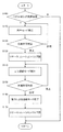
- FIG. 3 is a flowchart showing a control routine of power consumption control according to the first embodiment.
- FIG. 4 is a timing chart when the control routine of FIG. 3 is executed.
- FIG. 5 is a timing chart as a comparative example when the internal combustion engine is motored by the generator during deceleration control.
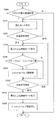
- FIG. 6 is a flowchart showing a control routine of power consumption control according to the second embodiment.
- FIG. 7 is a flowchart showing a control routine of power consumption control according to the third embodiment.
- FIG. 1 is a schematic configuration diagram of a hybrid system 1 of a hybrid vehicle to which this embodiment is applied.
- the hybrid system 1 exchanges electric power with the internal combustion engine 2, a generator 3 that is driven by the internal combustion engine 2 to generate power, a traveling motor 4 that drives the drive wheels 6, and the generator 3 and the traveling motor 4. And a battery 5.
- the hybrid system 1 is a series hybrid system in which the internal combustion engine 2 is used only for power generation, and the drive wheels 6 are exclusively driven by the traveling motor 4.
- the internal combustion engine 2 is a gasoline engine or a diesel engine having a plurality of cylinders. In the present embodiment, the case where the internal combustion engine 2 is a gasoline engine will be described.
- the internal combustion engine 2 is mechanically connected to the generator 3 via a speed reducer (not shown).
- the generator 3 is connected to the battery 5 so that power can be transmitted and received.
- the driving force of the internal combustion engine 2 is transmitted to the generator 3, and the generator 3 generates power by the driving force of the internal combustion engine 2.
- the battery 5 is charged with the electric power generated by the generator 3.
- the electric power charged in the battery 5 is transmitted to the traveling motor 4, and the traveling motor 4 is driven by the electric power supplied from the battery 5.
- the hybrid vehicle travels when the drive wheels 6 are rotated by the driving force of the traveling motor 4.
- the traveling motor 4 applies regenerative braking force to the drive wheels 6 to generate regenerative power, and the regenerative power is charged in the battery 5.
- the internal combustion engine 2, the generator 3, and the traveling motor 4 are controlled by a controller 26 described later.
- FIG. 2 is a schematic configuration diagram of the power generation system 100.
- the generator 3 is mechanically connected to the internal combustion engine 2 via the speed reducer (not shown).
- an air flow sensor 16 that detects the intake amount
- a compressor 7A of the turbocharger 7 that adjusts the amount of air supplied to the internal combustion engine 2.
- a throttle valve 8 that adjusts the amount of air supplied to the internal combustion engine 2.
- an intercooler (W-CAC) 9 that cools the air that has been pressurized by the compressor 7A and has increased in temperature.
- the intercooler 9 uses a water-cooled type that performs heat exchange between the air whose temperature has risen and the cooling medium, but is not limited to this.
- a water-cooled type that performs heat exchange between the air whose temperature has risen and the cooling medium.
- the intake system of the internal combustion engine 2 is provided with a communication passage 21 that connects the upstream intake passage 10 upstream of the compressor 7A and the downstream intake passage 11 downstream of the compressor 7A to bypass the compressor 7A.
- a recirculation valve 22 that opens and closes the communication passage 21 is arranged in the communication passage 21.
- the recirculation valve 22 is opened and closed by an electric actuator. Control of opening / closing drive of the recirculation valve 22 is performed by a controller 26 described later.
- the turbine 7B of the turbocharger 7, the first exhaust purification catalyst 14, and the second exhaust purification catalyst 15 are arranged in this order from the upstream side.
- a compressor 7A and a turbine 7B are coaxially provided via a shaft 7C, and when the turbine 7B rotates, the compressor 7A also rotates and compresses the air supplied to the internal combustion engine 2. Further, the turbocharger 7 can also rotate the shaft 7C by the power of the electric motor 7D and thereby rotate the compressor 7A. Furthermore, the turbocharger 7 can also perform regenerative power generation when the turbine 7B is rotated by the exhaust energy. The battery 5 is charged with the regenerated electric power.
- the first exhaust purification catalyst 14 is a catalytic converter including, for example, a three-way catalyst and a filter for collecting exhaust particulates.
- the second exhaust purification catalyst 15 is, for example, a NOx catalyst that collects NOx in the exhaust.
- An air-fuel ratio sensor 17 that detects the air-fuel ratio of the exhaust is arranged near the inlet of the first exhaust purification catalyst 14, and an O 2 sensor 18 that detects the oxygen concentration of the exhaust is arranged near the outlet.
- NOx sensors 19 and 20 for detecting the NOx concentration in the exhaust are arranged near the inlet and the outlet of the second exhaust purification catalyst 15.
- the exhaust system of the internal combustion engine 2 is also provided with a bypass passage 23 that connects the upstream exhaust passage 12 upstream of the turbine 7B and the downstream exhaust passage 13 downstream of the turbine 7B to bypass the turbine 7B.
- a wastegate valve 24 that opens and closes the bypass passage 23 is arranged in the bypass passage 23.
- the waste gate valve 24 is opened and closed by an electric actuator. Control of opening / closing drive of the waste gate valve 24 is performed by a controller 26 described later.
- the controller 26 reads detection signals from the air flow sensor 16, the air-fuel ratio sensor 17, the O2 sensor 18, the NOx sensors 19 and 20, the accelerator opening sensor 25, and a water temperature sensor, a crank angle sensor, a vehicle speed sensor and the like (not shown). . Then, the controller 26 controls the drive of the internal combustion engine 2 based on these detection signals.
- the accelerator pedal of the present embodiment is provided with an acceleration region and a deceleration region in the operation range from fully closed to fully opened, and when the opening of the accelerator pedal is in the acceleration region, the traveling motor 4 generates a driving force. However, when it is in the deceleration region, the traveling motor 4 generates a regenerative braking force. That is, the accelerator opening sensor 25 can detect both the acceleration request and the deceleration request.
- the controller 26 calculates a charge rate (State of Charge: SOC) based on a detection value of a current sensor (not shown) that detects a charging / discharging current of the battery 5, and the power generation amount of the generator 3 according to the SOC. To control. In the following description, the charging rate may be replaced with the charging amount.
- SOC State of Charge
- the controller 26 is composed of a microcomputer including a central processing unit (CPU), a read only memory (ROM), a random access memory (RAM), and an input / output interface (I / O interface). It is also possible to configure the controller 26 with a plurality of microcomputers.
- CPU central processing unit
- ROM read only memory
- RAM random access memory
- I / O interface input / output interface
- the threshold value here is a value that is determined based on the regenerative power and the battery capacity when regenerative braking force is generated according to the deceleration request.
- the electric power of the battery 5 or the surplus regenerated electric power is supplied to the generator 3 and the electric power is consumed by causing the internal combustion engine 2 to be motored by the generator 3. Conceivable.
- air is sent to the first exhaust purification catalyst 14 and the second exhaust purification catalyst 15 by the pumping operation of the piston of the internal combustion engine 2 during motoring.
- the first exhaust gas purification catalyst 14 and the second exhaust gas purification catalyst 15 are significantly larger than the exhaust gas when the internal combustion engine 2 is operating autonomously. Cold air will flow in.
- the catalyst temperature decreases, and when the power generation request subsequently occurs and the internal combustion engine 2 is driven, the exhaust gas purification performance may decrease.
- the controller 26 drives the turbocharger 7 with the electric power of the battery 5 in order to secure the regenerative braking force while suppressing the temperature decrease of the first exhaust purification catalyst 14 and the second exhaust purification catalyst 15.
- the power of the battery 5 is consumed.
- the control for power consumption will be referred to as power consumption control.
- Fig. 3 shows a control routine for power consumption control. This control routine is pre-programmed in the controller 26. The contents of the control routine will be described below in accordance with the steps of FIG. It is assumed that the internal combustion engine 2 is stopped and the throttle valve 8 is fully closed during execution of this control routine.
- step S100 the controller 26 determines whether the accelerator opening is in the deceleration region. If the determination result is yes, the controller 26 executes the process of step S110, and if the determination result is no, ends the routine of this time.
- step S110 the controller 26 determines to execute the regenerative mode.
- the regenerative mode referred to here is a mode in which the traveling motor 4 is caused to generate a regenerative braking force.
- step S120 the controller 26 executes the charge permission determination described later. If the charge is permitted, the process returns to step S110. If the charge is prohibited, the controller 26 performs the process of step S130.
- the charge permission determination is to determine whether or not the current SOC of the battery 5 is equal to or higher than the threshold value described above.
- the current SOC of the battery 5 is calculated by the controller 26 based on the detection value of the sensor that detects the charge / discharge current of the battery 5 as described above.
- the threshold value is set as follows, for example.
- the controller 26 first sets a target deceleration according to the accelerator opening degree, and calculates a target regenerative braking force for realizing the target deceleration. Next, the controller 26 calculates the regenerative electric power when the target regenerative braking force is generated.
- the controller 26 calculates the upper limit value of the SOC capable of charging the regenerative power of this time based on the capacity of the battery 5, and sets it as the threshold value. For the sake of simplicity, it may be determined that the battery 5 is prohibited when the battery 5 is fully charged and is permitted when the battery 5 is not fully charged.
- the controller 26 opens the recirculation valve 22 in step S130. Then, the controller 26 drives the electric motor 7D in step S140. That is, the controller 26 drives the turbocharger 7 with the power of the battery 5.
- the drive command value for the electric motor 7D at this time is, for example, the rated output.
- step S140 After driving the turbocharger 7 in step S140, the controller 26 executes the charge permission determination again in step S150. This is to determine whether or not the battery 5 is in a chargeable state by consuming electric power to drive the turbocharger 7. When the controller 26 determines that charging is prohibited, the controller 26 returns to the process of step S140 and continues driving the turbocharger 7. On the other hand, when it is determined that the charge is permitted, the controller 26 ends the drive of the turbocharger 7 by the electric power in step S160, closes the recirculation valve 22 in step S170, and ends the present control routine.
- step S130 the controller 26 may open the recirculation valve 22 and the wastegate valve 24. Since the air inlet of the intake system is open, new air is introduced when the compressor 7A rotates, and the pressure in the downstream intake passage 11 rises. Therefore, by opening the waste gate valve 24, the air supercharged by the compressor 7A is circulated in the upstream intake passage 10. On the other hand, if the internal combustion engine 2 does not rotate, new air is not supplied to the exhaust system. Therefore, even if the turbine 7B rotates while the wastegate valve 24 is closed, the air around the turbine 7B is only agitated.
- the controller 26 closes the wastegate valve 24 at the same time as closing the recirculation valve 22 in step S170.
- FIG. 4 is a timing chart when the above control routine is executed.
- FIG. 5 is a comparative example that is not included in the scope of the present invention, and is a timing chart in the case where surplus power is consumed by powering the generator 3 and motoring the internal combustion engine 2.
- the catalyst inflow air amount and catalyst temperature in both figures are the inflow air amount and temperature of the first exhaust purification catalyst 14, respectively.
- the inflow air amount and temperature of the second exhaust purification catalyst 15 are not shown, they show the same tendency as the inflow air amount and temperature of the first exhaust purification catalyst 14.
- the drive motor switches from power running to regeneration at timing T1, and the battery 5 switches from a discharged state to a charged state accordingly.
- the SOC of the battery 5 switches from a decrease to an increase.
- the SOC of the battery 5 is lower than the threshold value.
- the turbocharger 7 (eTC) starts to be driven by the power of the battery 5, and the rotation speed of the turbocharger 7 increases. As a result, the SOC of the battery 5 starts to decrease. Since the internal combustion engine 2 is stopped and the throttle valve 8 is closed accordingly, the catalyst inflow air amount does not increase even if the compressor 7A rotates. In FIG. 4, the catalyst inflow air amount slightly increases after timing T2. This is because the turbine 7B rotates with the rotation of the compressor 7A, so that part of the air in the exhaust system is purified by the first exhaust gas purification. This is because it flows into the catalyst 14. However, the amount of air flowing into the catalyst at this time is very small, and the influence on the catalyst temperature can be ignored.
- the catalyst temperature decreases after timing T2 with the same slope as before timing T2.
- FIG. 5 the same as in FIG. 4 up to the timing T2, but when the SOC of the battery 5 reaches the threshold value at the timing T2, the generator 3 powers the internal combustion engine 2 by the power of the battery 5.
- the amount of air flowing into the catalyst increases.
- the air that flows into the first exhaust purification catalyst 14 is the air that has passed through the internal combustion engine 2 without burning, and therefore promotes a decrease in the catalyst temperature.
- the deceleration control for generating the braking force by regeneratively driving the traveling motor 4 is executed, and the SOC of the battery 5 is executed when the deceleration control is executed. If the (charging rate) is equal to or higher than the threshold value, the power consumption control is performed in which the turbocharger 7 is driven by the power of the battery 5 while the internal combustion engine 2 is stopped. Thereby, the electric power of the battery 5 is consumed, so that the regenerative braking by the traveling motor 4 can be performed.
- the throttle valve 8 when executing the power consumption control, the throttle valve 8 is closed and the recirculation valve 22 (first recirculation valve) is opened. As a result, it is possible to prevent the electric motor 7D from being overloaded due to the pressure increase in the downstream intake passage 11.
- the hybrid system 1 and the power generation system 100 according to this embodiment are the same as those in the first embodiment. Further, the present embodiment is similar to the first embodiment in that the turbocharger 7 is driven by electric power for power consumption when the SOC of the battery 5 is equal to or higher than the threshold value during deceleration, but the electric power is the same. A part of the control routine for consumption is different from that of the first embodiment. Hereinafter, this difference will be mainly described.
- FIG. 6 is a control routine for power consumption control according to this embodiment. This control routine is pre-programmed in the controller 26. The contents of the control routine will be described below in accordance with the steps of FIG. It is assumed that the internal combustion engine 2 is stopped and the throttle valve 8 is fully closed during execution of this control routine.
- steps S200 to S230 and steps S250 to S270 are the same as the processes of steps S100 to S130 and steps S150 to S170 of FIG. 3 described in the first embodiment, and therefore description thereof will be omitted. That is, the difference between the control routine of FIG. 6 and the control routine of FIG. 3 is step S240, step S242, and step S244. The processing in these steps will be described below.
- step S240 the controller 26 drives the electric motor 7D.
- the drive command value for the electric motor 7D at this time is set according to the regenerative electric power.
- the regenerative power is determined based on the size of the accelerator opening. That is, the required deceleration is determined based on the accelerator opening, and the regenerative braking force for realizing the deceleration is determined. Then, if the regenerative braking force is determined, the regenerative power is determined.
- the controller 26 sets a drive command value such that the power consumption of the electric motor 7D is larger than the regenerative power determined in this way.
- the drive command value is, for example, the output [kW], and is set by mapping the relationship between the power consumption and the output in advance and searching the map with the required power consumption. By setting the drive command value in this way, it is possible to prevent excessive power consumption.
- step S242 the controller 26 determines whether the rotation speed of the turbocharger 7, that is, the rotation speed of the electric motor 7D is higher than a threshold value.
- the threshold value is a rotation speed that is expected to be reached by inputting a drive command value. That is, the controller 26 stores the rotation speed of the electric motor 7D for each drive command value in advance as data, and determines the threshold value used in step S242 according to the drive command value set in step S240.
- the rotation speed of the electric motor 7D is detected by, for example, a sensor that detects the rotation speed of the shaft 7C.
- step S250 if the rotation speed of the electric motor 7D is equal to or lower than the threshold value, the process of step S250 is executed, and if not, the process of step S244 is executed.
- step S244 the controller 26 reduces the opening degree of the recirculation valve 22 by a preset amount.
- the fact that the rotation speed of the electric motor 7D is higher than the threshold means that the load is lower than expected, that is, the actual power consumption is lower than that assumed in step S240. Therefore, in this step, the opening degree of the recirculation valve 22 is decreased.
- the reduction amount of the opening degree of the recirculation valve 22 is, for example, several degrees. This can prevent the rotation speed of the electric motor 7D from being excessively lower than the threshold value.
- the turbocharger 7 can consume more power than the electric power regenerated by the traveling motor 4, and it is possible to avoid excessive power consumption of the turbocharger 7.
- the hybrid system 1 according to this embodiment is the same as that of the first embodiment.
- the power generation system 100 according to this embodiment is basically the same as the first embodiment, but the recirculation valve 22 opens and closes according to the pressure difference between the pressure in the downstream intake passage 11 and the atmospheric pressure. It is different from the first embodiment in that it is a pressure-sensitive type.
- the present embodiment is similar to the first embodiment in that the turbocharger 7 is driven by electric power for power consumption when the SOC of the battery 5 is equal to or higher than the threshold value during deceleration. A part of the control routine for consumption is different from that of the first embodiment. Hereinafter, this difference will be mainly described.
- FIG. 7 is a control routine for power consumption control according to this embodiment. This control routine is pre-programmed in the controller 26. The contents of the control routine will be described below in accordance with the steps of FIG. It is assumed that the internal combustion engine 2 is stopped and the throttle valve 8 is fully closed during execution of this control routine.
- Steps S300 to S320 are the same as steps S100 to S120 in FIG. Since step S330 is the same as step S140 of FIG. 3, description thereof will be omitted.
- step S340 the controller 26 determines whether the recirculation valve 22 is closed. Specifically, if the detection value of the pressure sensor that detects the pressure in the downstream intake passage 11 is lower than the pressure at which the recirculation valve 22 opens, it is determined that the valve is closed. The controller 26 executes the process of step S350 in the valve closed state, and executes the process of step S360 in the valve open state.
- step S350 the controller 26 opens the closed throttle valve 8.
- the opening at this time is extremely small, for example, about several degrees.
- step S350 After opening the throttle valve 8 in step S350, the controller 26 executes the processing from step S360 to step S380.
- steps S360 and S370 are the same as steps S150 and S160 of FIG.
- step S380 the controller 26 returns the opening degree of the throttle valve 8 to the original, that is, closes it, and ends this routine.
- the throttle valve 8 is opened by a small amount. If the turbocharger 7 is continuously driven in the state where the recirculation valve 22 and the throttle valve 8 are closed, the pressure in the downstream side intake passage 11 rises and the load of the electric motor 7D increases. At this time, if the output of the electric motor 7D is smaller than the output required for rotationally driving against the load, the electric motor 7D will stop. Therefore, by opening the throttle valve 8 which can be controlled to an arbitrary opening degree, air is released downstream from the throttle valve 8. In the internal combustion engine 2 which is a multi-cylinder engine, all the intake valves are not closed in the stopped state.
- the air that has passed through the throttle valve 8 flows into the cylinder whose intake valve is open. Even if the exhaust valve of the cylinder into which the air has flown is closed, the air escapes to the crankcase through the gap between the cylinder wall and the piston ring, so that the electric motor 7D does not stop due to overload.
- the power generation system 100 has an intake passage (downstream intake passage 11) downstream of the compressor 7A and upstream of the throttle valve 8 and an intake passage upstream of the compressor 7A (upstream intake passage 10).
- the recirculation valve 22 (2nd recirculation valve) which opens and closes the communicating path 21 according to a pressure difference is provided. Then, when the power consumption control is executed and the output of the turbocharger 7 is smaller than the output required to open the recirculation valve 22, the opening degree of the throttle valve 8 is larger than the closed state. Set to a predetermined opening. As a result, even if the output of the electric motor 7D is smaller than the output required to open the recirculation valve 22, it is possible to consume power by driving the turbocharger 7.
Landscapes
- Engineering & Computer Science (AREA)
- Mechanical Engineering (AREA)
- Combustion & Propulsion (AREA)
- Chemical & Material Sciences (AREA)
- Transportation (AREA)
- Power Engineering (AREA)
- General Engineering & Computer Science (AREA)
- Sustainable Energy (AREA)
- Sustainable Development (AREA)
- Life Sciences & Earth Sciences (AREA)
- Automation & Control Theory (AREA)
- Supercharger (AREA)
- Hybrid Electric Vehicles (AREA)
- Electric Propulsion And Braking For Vehicles (AREA)
- Output Control And Ontrol Of Special Type Engine (AREA)
Abstract
内燃機関と、内燃機関により駆動される発電機と、電力によるカ行駆動及び駆動輪からの入力による回生駆動の両機能を有する走行用モータと、発電機及び走行用モー夕と電力の授受を行なうバッテリと、バッテリの電力及び内燃機関から排出される排気エネルギのいずれでも駆動可能なターボ過給機と、を備えるハイブリッド車両を制御するハイブリツド車両制御方法は、減速要求が発生した場合には走行用モータを回生駆動することで制動力を発生させる減速制御を実行し、減速制御を実行する場合にバッテリの充電率が閾値以上であれば、内燃機関を停止した状態でターボ過給機をバッテリの電力により駆動する電力消費制御を実行する。
Description
本発明は、ハイブリッド車両の制御方法及び制御装置に関する。
内燃機関により駆動される発電機と、発電機の発電電力を蓄電するバッテリと、バッテリの電力で駆動される走行用モータと、を備えるシリーズハイブリッド車両が知られている。シリーズハイブリッド車両では、走行用モータによる回生制動を行なう場合に、バッテリが満充電に達した以降は、回生を行なってもバッテリへの充電ができないため電流値が小さくなり、十分な制動力を確保できなくなる。JP8−79914Aには、バッテリが満充電に達した以降も制動力を確保するための制御として、発電機により内燃機関を回転駆動することでバッテリの電力を消費する制御が開示されている。
しかしながら、上記文献の制御のように発電機により内燃機関を回転駆動させると、内燃機関のピストンのポンピング動作によって空気が排気浄化触媒に送られて、排気浄化触媒の温度が低下するという問題がある。
そこで本発明は、減速時に、排気浄化触媒の温度を低下させることなく、バッテリの電力を消費する制御方法及び制御装置を提供することを目的とする。
本発明のある態様によるハイブリッド車両制御方法は、内燃機関と、内燃機関により駆動される発電機と、電力による力行駆動及び駆動輪からの入力による回生駆動の両機能を有する走行用モータと、発電機及び走行用モータと電力の授受を行なうバッテリと、バッテリの電力及び内燃機関から排出される排気エネルギのいずれでも駆動可能なターボ過給機と、を備えるハイブリッド車両を制御する。ハイブリッド車両制御方法において、減速要求が発生した場合には、走行用モータを回生駆動することで制動力を発生させる減速制御を実行し、減速制御を実行する場合にバッテリの充電率が閾値以上であれば、内燃機関を停止した状態でターボ過給機をバッテリの電力により駆動する電力消費制御を実行する。
本発明のある態様によるハイブリッド車両制御装置は、内燃機関と、内燃機関の動力により駆動される発電機と、電力による力行駆動及び駆動輪からの入力による回生駆動の両機能を有する走行用モータと、発電機及び走行用モータと電力の授受を行なうバッテリと、バッテリの電力及び内燃機関から排出される排気エネルギのいずれでも駆動可能なターボ過給機と、発電機、走行用モータ及びターボ過給機を制御する制御部と、を備える。そして、制御部は、減速要求が発生した場合には、走行用モータを回生駆動することで制動力を発生させる減速制御を実行し、減速制御を実行する場合にバッテリの充電率が閾値以上であれば、内燃機関を停止した状態でターボ過給機をバッテリの電力により駆動する電力消費制御を実行するようプログラムされている。
以下、図面を参照して、本発明の実施形態について説明する。
(第1実施形態)
まず、第1実施形態について、図1から図5を参照して説明する。
まず、第1実施形態について、図1から図5を参照して説明する。
図1は、本実施形態を適用するハイブリッド車両のハイブリッドシステム1の概略構成図である。
ハイブリッドシステム1は、内燃機関2と、内燃機関2により駆動されて発電する発電機3と、駆動輪6を駆動する走行用モータ4と、発電機3及び走行用モータ4と電力の授受を行なうバッテリ5と、を有する。ハイブリッドシステム1は、内燃機関2を発電のみに使用し、駆動輪6は専ら走行用モータ4により駆動される、シリーズハイブリッド方式である。
内燃機関2は、複数の気筒を有するガソリンエンジンまたはディーゼルエンジンである。なお、本実施形態では内燃機関2がガソリンエンジンである場合について説明する。
内燃機関2は、減速機(不図示)を介して発電機3に機械的に連結される。発電機3は、バッテリ5に送受電可能に接続されている。
内燃機関2の駆動力は発電機3に伝達され、発電機3は内燃機関2の駆動力によって発電する。発電機3の発電電力はバッテリ5に充電される。バッテリ5に充電された電力は、走行用モータ4に伝達され、走行用モータ4はバッテリ5から供給される電力によって駆動する。ハイブリッド車両は、駆動輪6が走行用モータ4の駆動力により回転することで走行する。また、減速する際は、走行用モータ4は駆動輪6に回生制動力を印加することで回生電力を発生させ、この回生電力はバッテリ5に充電される。
内燃機関2、発電機3及び走行用モータ4は、後述するコントローラ26により制御される。
次に、内燃機関2と発電機3とを有する発電システム100について説明する。
図2は発電システム100の概略構成図である。
上述した通り、内燃機関2には、減速機(不図示)を介して発電機3が機械的に連結される。
内燃機関2の吸気系統には、上流側から順に、吸気量を検出するエアフローセンサ16と、ターボ過給機7のコンプレッサ7Aと、内燃機関2に供給される空気量を調節するスロットルバルブ8と、コンプレッサ7Aにより加圧されて温度上昇した空気を冷却するインタークーラ(W−CAC)9と、が配置される。
インタークーラ9は、本実施形態では温度上昇した空気と冷却用媒体との間で熱交換を行なう水冷式を用いるが、これに限られない。例えば、温度上昇した空気と大気との間で熱交換を行なう空冷式を用いることもできる。
また、内燃機関2の吸気系統には、コンプレッサ7Aより上流の上流側吸気通路10と下流の下流側吸気通路11とをコンプレッサ7Aを迂回して連通させる連通路21が配置される。そして、連通路21には、連通路21を開閉するリサーキュレーションバルブ22が配置される。リサーキュレーションバルブ22は、電動アクチュエータにより開閉駆動する。リサーキュレーションバルブ22の開閉駆動の制御は後述するコントローラ26により行なわれる。
内燃機関2の排気系統には、上流側から順に、ターボ過給機7のタービン7Bと、第1排気浄化触媒14と、第2排気浄化触媒15とが配置される。
ターボ過給機7は、コンプレッサ7Aとタービン7Bとがシャフト7Cを介して同軸に設けられ、タービン7Bが回転するとコンプレッサ7Aも回転し、内燃機関2に供給される空気を圧縮する。また、ターボ過給機7は、電動モータ7Dの動力によってシャフト7Cを回転させ、これによりコンプレッサ7Aを回転させることもできる。さらに、ターボ過給機7は、タービン7Bが排気エネルギにより回転する際に回生発電することも可能である。回生発電した電力はバッテリ5に充電される。
第1排気浄化触媒14は、例えば三元触媒と排気微粒子捕集用のフィルタとを備える触媒コンバータである。第2排気浄化触媒15は、例えば排気中のNOxを捕集するNOx触媒である。
第1排気浄化触媒14の入口付近には、排気の空燃比を検出する空燃比センサ17が配置され、出口付近には排気の酸素濃度を検出するO2センサ18が配置される。第2排気浄化触媒15の入口付近及び出口付近には排気中のNOx濃度を検出するNOxセンサ19、20が配置される。
また、内燃機関2の排気系統には、タービン7Bより上流の上流側排気通路12と下流の下流側排気通路13とをタービン7Bを迂回して連通するバイパス通路23が配置される。バイパス通路23には、バイパス通路23を開閉するウェイストゲートバルブ24が配置される。ウェイストゲートバルブ24は電動アクチュエータにより開閉駆動する。ウェイストゲートバルブ24の開閉駆動の制御は後述するコントローラ26により行なわれる。
コントローラ26は、エアフローセンサ16、空燃比センサ17、O2センサ18、NOxセンサ19、20、及びアクセル開度センサ25と、その他に図示しない水温センサやクランク角度センサや車速センサ等の検出信号を読み込む。そして、コントローラ26はこれらの検出信号に基づいて内燃機関2の駆動を制御する。
なお、本実施形態のアクセルペダルは、全閉から全開までの操作範囲に加速領域と減速領域とを設け、アクセルペダルの開度が加速領域にある場合には走行用モータ4は駆動力を発生し、減速領域にある場合には走行用モータ4は回生制動力を発生する。すなわち、アクセル開度センサ25は加速要求及び減速要求のいずれも検出することができる。
また、コントローラ26は、バッテリ5の充放電電流を検出する電流センサ(不図示)の検出値に基づいて充電率(State of Charge:SOC)を算出し、SOCに応じて発電機3の発電量を制御する。なお、以下の説明において、充電率を充電量に置き換えても構わない。
なお、コントローラ26は、中央演算装置(CPU)、読み出し専用メモリ(ROM)、ランダムアクセスメモリ(RAM)及び入出力インタフェース(I/Oインタフェース)を備えたマイクロコンピュータで構成される。コントローラ26を複数のマイクロコンピュータで構成することも可能である。
ハイブリッド車両は、上述した通り、減速する際は走行用モータ4で駆動輪6に回生制動力を印加することで回生電力を発生させ、回生電力をバッテリ5に充電する。ただし、バッテリ5のSOCが所定の閾値以上となって充電可能電力が回生電力より低くなると、走行用モータ4が回生動作を行なってもバッテリ5への充電ができなくなって電流値が低下するため、十分な制動力が得られなくなる。
ここでいう閾値は、減速要求に応じた回生制動力を発生させる場合の回生電力とバッテリ容量とに基づいて定まる値である。要求される回生制動力が大きくなるほど回生電力は大きくなるので、閾値は低くなる。また、バッテリ容量が大きいほど、電力を充放電することによるSOCの変動量は小さくなるので、閾値は高くなる。なお、簡単のため、バッテリ5が満充電状態のときに閾値以上であると判断してもよい。
このような状況において制動力を確保する方策として、バッテリ5の電力または余剰の回生電力を発電機3に供給して、発電機3により内燃機関2をモータリングさせることで電力を消費することが考えられる。
しかし、上記の方策では、モータリング中における内燃機関2のピストンのポンピング動作によって空気が第1排気浄化触媒14及び第2排気浄化触媒15に送られる。この場合、空気は内燃機関2を燃焼することなく通過するので、第1排気浄化触媒14及び第2排気浄化触媒15には、内燃機関2が自律運転している場合の排気に比べて大幅に低温の空気が流入することとなる。その結果、触媒温度が低下し、その後に発電要求が生じて内燃機関2を駆動させた際に、排気浄化性能が低下するおそれがある。
そこで、コントローラ26は、第1排気浄化触媒14及び第2排気浄化触媒15の温度低下を抑制しつつ回生制動力を確保するために、ターボ過給機7をバッテリ5の電力により駆動することでバッテリ5の電力を消費する。以下、この電力消費のための制御を電力消費制御と称する。
図3は、電力消費制御の制御ルーチンである。本制御ルーチンはコントローラ26に予めプログラムされている。以下、制御ルーチンの内容について図3のステップにしたがって説明する。なお、本制御ルーチンの実行時には、内燃機関2は停止し、スロットルバルブ8は全閉状態になっているものとする。
ステップS100で、コントローラ26はアクセル開度が減速領域にあるか否かを判定する。コントローラ26は、判定結果がyesの場合はステップS110の処理を実行し、noの場合は今回のルーチンを終了する。
ステップS110で、コントローラ26は回生モードの実行を決定する。ここでいう回生モードとは、走行用モータ4に回生制動力を発生させるモードのことである。
ステップS120で、コントローラ26は後述する充電許可判定を実行し、充電が許可される場合はステップS110の処理に戻り、充電が禁止される場合はステップS130の処理を実行する。
充電許可判定は、具体的にはバッテリ5の現在のSOCが上述した閾値以上であるか否かを判定するものである。バッテリ5の現在のSOCは、上述した通りバッテリ5の充放電電流を検出するセンサの検出値に基づいてコントローラ26が算出する。閾値は、例えば次のように設定する。コントローラ26は、まず、アクセル開度に応じて目標減速度を設定し、目標減速度を実現するための目標回生制動力を算出する。次に、コントローラ26は目標回生制動力を発生させた場合の回生電力を算出する。そして、コントローラ26は、バッテリ5の容量に基づいて、今回の回生電力を充電可能なSOCの上限値を算出し、それを閾値とする。なお、簡単のために、バッテリ5が満充電の場合は禁止と判定し、満充電でない場合は許可と判定してもよい。
充電禁止と判定した場合、コントローラ26はステップS130でリサーキュレーションバルブ22を開弁させる。そして、コントローラ26は、ステップS140で電動モータ7Dを駆動させる。つまり、コントローラ26はターボ過給機7をバッテリ5の電力により駆動させる。このときの電動モータ7Dへの駆動指令値は、例えば定格出力とする。
リサーキュレーションバルブ22を開弁すると、コンプレッサ7Aで過給された空気は連通路21を介してコンプレッサ7Aの下流側から上流側へ循環するので、スロットルバルブ8を閉じたままでも下流側吸気通路11の圧力が過剰に上昇することがない。これにより、圧力上昇による下流側吸気通路11及びスロットルバルブ8の変形や、コンプレッサ7Aの回転負荷の過剰な上昇を防止できる。
コントローラ26は、ステップS140でターボ過給機7を駆動させたら、ステップS150で充電許可判定を再び実行する。これは、ターボ過給機7を駆動するために電力を消費したことで、バッテリ5が充電可能な状態になったか否かを判定するためである。コントローラ26は、充電禁止と判定した場合はステップS140の処理に戻ってターボ過給機7の駆動を継続する。一方、充電許可と判定した場合は、コントローラ26はステップS160でターボ過給機7の電力による駆動を終了し、ステップS170でリサーキュレーションバルブ22を閉弁して、本制御ルーチンを終了する。
なお、ステップS130において、コントローラ26はリサーキュレーションバルブ22を開弁するとともに、ウェイストゲートバルブ24も開弁するようにしてもよい。吸気系統は空気導入口が開放状態なため、コンプレッサ7Aが回転すると新たな空気が導入されて下流側吸気通路11の圧力が上昇する。そこで、ウェイストゲートバルブ24を開くことによりコンプレッサ7Aで過給された空気を上流側吸気通路10に循環させる。これに対し、内燃機関2が回転しなければ排気系統には新たな空気が供給されない。したがって、ウェイストゲートバルブ24が閉弁したままタービン7Bが回転しても、タービン7Bの周辺の空気が撹拌されるだけである。ただし、ウェイストゲートバルブ24を開弁してタービン7Bの上流側と下流側との循環経路を形成することにより、第1排気浄化触媒14及び第2排気浄化触媒15への空気の流れをより確実に遮断することができる。ステップS130でウェイストゲートバルブ24を開弁する場合には、コントローラ26はステップS170でリサーキュレーションバルブ22を閉弁するのと同時にウェイストゲートバルブ24も閉弁する。
次に、上記制御ルーチンを実行した場合の作用効果について説明する。
図4は上記制御ルーチンを実行した場合のタイミングチャートである。図5は、本発明の範囲に含まれない比較例であり、発電機3を力行駆動して内燃機関2をモータリングすることにより余剰の電力を消費する場合のタイミングチャートである。
図4及び図5は、いずれもアクセル開度(APO)が加速領域にあり定速走行している状態で、タイミングT1においてアクセル開度が減速領域に入って車両を減速させる場合について示している。両図中の触媒流入空気量及び触媒温度は、それぞれ第1排気浄化触媒14の流入空気量及び温度である。なお、第2排気浄化触媒15の流入空気量及び温度は図示しないが、第1排気浄化触媒14の流入空気量及び温度と同様の傾向を示す。
図4では、タイミングT1において走行用モータは力行から回生に切り替わり、これに伴いバッテリ5は放電状態から充電状態に切り替わる。これにより、バッテリ5のSOCは低下から上昇に切り替わる。ただし、タイミングT1において、バッテリ5のSOCは閾値より低い。
タイミングT1以降、触媒流入空気量はゼロであるが触媒温度は低下する。これは、排気が流入せず、かつ触媒自身が放熱するからである。
そして、タイミングT2においてバッテリ5のSOCが閾値に到達すると、ターボ過給機7(eTC)がバッテリ5の電力で駆動開始し、ターボ過給機7の回転速度が上昇する。これによりバッテリ5のSOCは減少に転じる。また、内燃機関2は停止しており、これに伴いスロットルバルブ8は閉弁しているので、コンプレッサ7Aが回転しても、触媒流入空気量は増加しない。なお、図4においてはタイミングT2以降に触媒流入空気量が微増しているが、これはコンプレッサ7Aの回転に伴いタービン7Bが回転することで、排気系統にある空気の一部が第1排気浄化触媒14に流入するためである。ただし、このときの触媒流入空気量はごく微量であり、触媒温度に与える影響は無視し得る。
その結果、触媒温度はタイミングT2以降も、タイミングT2以前と同様の傾きで低下する。
これに対し図5では、タイミングT2までは図4と同様であるが、タイミングT2においてバッテリ5のSOCが閾値に到達すると、発電機3がバッテリ5の電力により力行して内燃機関2をモータリングさせる。内燃機関2がモータリングすることにより、触媒流入空気量が増大する。このとき第1排気浄化触媒14に流入する空気は、燃焼することなく内燃機関2を通過した空気なので、触媒温度の低下を促進する。
その結果、タイミングT2以降における触媒温度の低下の傾きは、図4のそれに比べて大きくなる。
上記の通り、本実施形態では、減速要求が発生した場合には、走行用モータ4を回生駆動することで制動力を発生させる減速制御を実行し、減速制御を実行する場合にバッテリ5のSOC(充電率)が閾値以上であれば、内燃機関2を停止した状態でターボ過給機7をバッテリ5の電力により駆動する電力消費制御を実行する。これにより、バッテリ5の電力が消費されるので、走行用モータ4による回生制動を行なうことができる。そして、電力消費制御を実行しても、第1排気浄化触媒14及び第2排気浄化触媒15へ空気が流入することがないので、第1排気浄化触媒14及び第2排気浄化触媒15の温度低下及び酸素ストレージ量の増大を抑制できる。
本実施形態では、電力消費制御を実行する場合に、スロットルバルブ8を閉弁し、かつリサーキュレーションバルブ22(第1リサーキュレーションバルブ)を開弁する。これにより、下流側吸気通路11内の圧力上昇により電動モータ7Dに過負荷がかかることを防止できる。
(第2実施形態)
次に、第2実施形態について図6を参照して説明する。
次に、第2実施形態について図6を参照して説明する。
本実施形態に係るハイブリッドシステム1及び発電システム100は第1実施形態と同様である。また、本実施形態は、減速時にバッテリ5のSOCが閾値を以上の場合には電力消費のためにターボ過給機7を電力で駆動する点も第1実施形態と同様であるが、その電力消費のための制御ルーチンの一部が第1実施形態と相違する。以下、この相違点を中心に説明する。
図6は、本実施形態に係る電力消費制御の制御ルーチンである。本制御ルーチンはコントローラ26に予めプログラムされている。以下、制御ルーチンの内容について図6のステップにしたがって説明する。なお、本制御ルーチンの実行時には、内燃機関2は停止し、スロットルバルブ8は全閉状態になっているものとする。
ステップS200からステップS230と、ステップS250からステップS270の各処理は、第1実施形態で説明した図3のステップS100からステップS130と、ステップS150からステップS170の各処理と同様なので説明を省略する。すなわち、図6の制御ルーチンと図3の制御ルーチンとの相違点は、ステップS240、ステップS242及びステップS244である。以下、これらのステップにおける処理について説明する。
ステップS240で、コントローラ26は電動モータ7Dを駆動させる。このときの電動モータ7Dへの駆動指令値は、回生電力に応じて設定される。回生電力は、アクセル開度の大きさに基づいて定まる。つまり、アクセル開度に基づいて必要となる減速度が定まり、その減速度を実現するための回生制動力が定まる。そして、回生制動力が定まれば回生電力が定まる。コントローラ26は、このようにして定まる回生電力よりも電動モータ7Dにおける消費電力が大きくなる駆動指令値を設定する。駆動指令値は、例えば出力[kW]であり、消費電力と出力との関係を予めマップ化しておき、必要となる消費電力でマップ検索することにより設定する。このように駆動指令値を設定することで、電力を過剰に消費することがなくなる。
ステップS242で、コントローラ26はターボ過給機7の回転速度、つまり電動モータ7Dの回転速度が、閾値より高いか否かを判定する。閾値は、駆動指令値を入力すれば到達するであろうと想定される回転速度である。すなわち、コントローラ26は、駆動指令値毎の電動モータ7Dの回転速度を予めデータとして記憶しておき、ステップS240で設定した駆動指令値に応じて、ステップS242で用いる閾値を決定する。電動モータ7Dの回転速度は、例えばシャフト7Cの回転速度を検出するセンサにより検出する。
判定の結果、電動モータ7Dの回転速度が閾値以下の場合には、ステップS250の処理を実行し、そうでない場合にはステップS244の処理を実行する。
ステップS244で、コントローラ26はリサーキュレーションバルブ22の開度を予め設定した量だけ減少させる。電動モータ7Dの回転速度が閾値より高いということは、負荷が想定よりも低いということであり、つまり実際の消費電力がステップS240において想定したものより小さいということである。そこで、本ステップでは、リサーキュレーションバルブ22の開度を減少させる。リサーキュレーションバルブ22の開度が減少すれば、下流側吸気通路11の圧力は高まり、電動モータ7Dの負荷が高まるので、電動モータ7Dの回転速度は低下する。すなわち、電動モータ7Dの消費電力が増大する。リサーキュレーションバルブ22の開度の減少量は、例えば数度とする。これにより、電動モータ7Dの回転速度が閾値より過剰に低くなることを抑制できる。
上記の通り、本実施形態では、電力消費制御を実行する場合に、閾値とバッテリ5の現在のSOC(充電率)とに基づいてリサーキュレーションバルブ22の開度を制御することにより、ターボ過給機7の消費電力を調整する。これにより、ターボ過給機7で走行用モータ4による回生電力より大きい電力を消費することができ、かつ、ターボ過給機7の消費電力が過剰に大きくなることを回避できる。
(第3実施形態)
次に、第3実施形態について図7を参照して説明する。
次に、第3実施形態について図7を参照して説明する。
本実施形態に係るハイブリッドシステム1は第1実施形態と同様である。本実施形態に係る発電システム100は、基本的には第1実施形態と同様であるが、リサーキュレーションバルブ22が下流側吸気通路11内の圧力と大気圧との差圧に応じて開閉する感圧式である点が第1実施形態と相違する。また、本実施形態は、減速時にバッテリ5のSOCが閾値を以上の場合には電力消費のためにターボ過給機7を電力で駆動する点も第1実施形態と同様であるが、その電力消費のための制御ルーチンの一部が第1実施形態と相違する。以下、この相違点を中心に説明する。
図7は、本実施形態に係る電力消費制御の制御ルーチンである。本制御ルーチンはコントローラ26に予めプログラムされている。以下、制御ルーチンの内容について図6のステップにしたがって説明する。なお、本制御ルーチンの実行時には、内燃機関2は停止し、スロットルバルブ8は全閉状態になっているものとする。
ステップS300からステップS320は、図3のステップS100からステップS120と同様なので説明を省略する。ステップS330は図3のステップS140と同様なので説明を省略する。
ステップS340で、コントローラ26はリサーキュレーションバルブ22が閉弁状態か否かを判定する。具体的には、下流側吸気通路11内の圧力を検出する圧力センサの検出値が、リサーキュレーションバルブ22が開弁する圧力より低ければ閉弁状態であると判定する。コントローラ26は、閉弁状態であればステップS350の処理を実行し、開弁状態であればステップS360の処理を実行する。
ステップS350で、コントローラ26は閉弁しているスロットルバルブ8を開弁させる。このときの開度はごく小さく、例えば数度程度とする。
コントローラ26は、ステップS350でスロットルバルブ8を開弁させたら、ステップS360からステップS380の処理を実行する。ステップS360及びステップS370の処理は図3のステップS150及びステップS160と同様なので説明を省略する。
コントローラ26は、ステップS380で、スロットルバルブ8の開度を元に戻し、つまり閉弁させて、本ルーチンを終了する。
上記の通り、本実施形態の電力消費制御は、ターボ過給機7を電力で駆動した場合にリサーキュレーションバルブ22が開弁しないときは、スロットルバルブ8を少量だけ開弁する。リサーキュレーションバルブ22及びスロットルバルブ8が閉弁した状態でターボ過給機7を駆動し続けると、下流側吸気通路11内の圧力が上昇し、電動モータ7Dの負荷が増大する。このとき、電動モータ7Dの出力が当該負荷に抗して回転駆動するのに必要な出力より小さいと、電動モータ7Dは停止してしまう。そこで、任意の開度に制御可能なスロットルバルブ8を開弁することで、空気をスロットルバルブ8より下流へ逃がす。多気筒エンジンである内燃機関2は、停止状態で全ての吸気弁が閉弁状態になることはない。したがって、スロットルバルブ8を通過した空気は、吸気弁が開いている気筒に流入する。空気が流入した気筒の排気弁が閉弁していたとしても、空気はシリンダ壁とピストンリングとの隙間を介してクランクケースに抜けるので、電動モータ7Dが過負荷により停止することはない。
上記の通り、本実施形態では、発電システム100がコンプレッサ7Aより下流かつスロットルバルブ8より上流の吸気通路(下流側吸気通路11)とコンプレッサ7Aより上流の吸気通路(上流側吸気通路10)との圧力差に応じて連通路21を開閉するリサーキュレーションバルブ22(第2リサーキュレーションバルブ)を備える。そして、電力消費制御を実行する場合に、ターボ過給機7の出力がリサーキュレーションバルブ22を開弁させるのに必要な出力より小さいときは、スロットルバルブ8の開度を閉弁状態より大きい所定開度に設定する。これにより、電動モータ7Dの出力がリサーキュレーションバルブ22を開弁させるのに必要な出力より小さい場合でも、ターボ過給機7を駆動することによる電力消費が可能となる。
以上、本発明の実施形態について説明したが、上記実施形態は本発明の適用例の一部を示したに過ぎず、本発明の技術的範囲を上記実施形態の具体的構成に限定する趣旨ではない。
Claims (5)
- 内燃機関と、
前記内燃機関により駆動される発電機と、
電力による力行駆動及び駆動輪からの入力による回生駆動の両機能を有する走行用モータと、
前記発電機及び前記走行用モータと電力の授受を行なうバッテリと、
前記バッテリの電力及び前記内燃機関から排出される排気エネルギのいずれでも駆動可能なターボ過給機と、
を備えるハイブリッド車両を制御するハイブリッド車両制御方法において、
減速要求が発生した場合には、前記走行用モータを回生駆動することで制動力を発生させる減速制御を実行し、
前記減速制御を実行する場合に前記バッテリの充電率が閾値以上であれば、前記内燃機関を停止した状態で前記ターボ過給機を前記バッテリの電力により駆動する電力消費制御を実行する、ハイブリッド車両制御方法。 - 請求項1に記載のハイブリッド車両制御方法において、
前記ハイブリッド車両は、前記ターボ過給機のコンプレッサより下流かつスロットルバルブより上流の吸気通路と前記コンプレッサより上流の吸気通路とを連通する連通路と、前記連通路を任意のタイミングで開閉可能な第1リサーキュレーションバルブと、をさらに備え、
前記電力消費制御を実行する場合に、前記スロットルバルブを閉弁し、かつ前記第1リサーキュレーションバルブを開弁する、ハイブリッド車両制御方法。 - 請求項2に記載のハイブリッド車両制御方法において、
前記電力消費制御を実行する場合に、前記閾値と前記バッテリの現在の充電率とに基づいて前記第1リサーキュレーションバルブの開度を制御することにより、前記ターボ過給機の消費電力を調整する、ハイブリッド車両制御方法。 - 請求項1に記載のハイブリッド車両制御方法において、
前記ハイブリッド車両は、前記ターボ過給機のコンプレッサより下流かつスロットルバルブより上流の吸気通路と前記コンプレッサより上流の吸気通路とを連通する連通路と、前記コンプレッサより下流かつ前記スロットルバルブより上流の吸気通路と前記コンプレッサより上流の吸気通路との圧力差に応じて前記連通路を開閉する第2リサーキュレーションバルブと、をさらに備え、
前記電力消費制御を実行する場合に、前記ターボ過給機の出力が前記第2リサーキュレーションバルブを開弁させるのに必要な出力より小さいときは、前記スロットルバルブの開度を閉弁状態より大きい所定開度に設定する、ハイブリッド車両制御方法。 - 内燃機関と、
前記内燃機関の動力により駆動される発電機と、
電力による力行駆動及び駆動輪からの入力による回生駆動の両機能を有する走行用モータと、
前記発電機及び前記走行用モータと電力の授受を行なうバッテリと、
前記バッテリの電力及び前記内燃機関から排出される排気エネルギのいずれでも駆動可能なターボ過給機と、
前記発電機、前記走行用モータ及び前記ターボ過給機を制御する制御部と、
を備えるハイブリッド車両を制御するハイブリッド車両制御装置において、
前記制御部は、
減速要求が発生した場合には、前記走行用モータを回生駆動することで制動力を発生させる減速制御を実行し、
前記減速制御を実行する場合に前記バッテリの充電率が閾値以上であれば、前記内燃機関を停止した状態で前記ターボ過給機を前記バッテリの電力により駆動する電力消費制御を実行するようプログラムされた、ハイブリッド車両制御装置。
Priority Applications (2)
| Application Number | Priority Date | Filing Date | Title |
|---|---|---|---|
| PCT/IB2018/001288 WO2020079463A1 (ja) | 2018-10-19 | 2018-10-19 | ハイプリッド車両の制御方法及び制御装置 |
| JP2020552162A JP7129488B2 (ja) | 2018-10-19 | 2018-10-19 | ハイブリッド車両の制御方法及び制御装置 |
Applications Claiming Priority (1)
| Application Number | Priority Date | Filing Date | Title |
|---|---|---|---|
| PCT/IB2018/001288 WO2020079463A1 (ja) | 2018-10-19 | 2018-10-19 | ハイプリッド車両の制御方法及び制御装置 |
Publications (1)
| Publication Number | Publication Date |
|---|---|
| WO2020079463A1 true WO2020079463A1 (ja) | 2020-04-23 |
Family
ID=70284637
Family Applications (1)
| Application Number | Title | Priority Date | Filing Date |
|---|---|---|---|
| PCT/IB2018/001288 Ceased WO2020079463A1 (ja) | 2018-10-19 | 2018-10-19 | ハイプリッド車両の制御方法及び制御装置 |
Country Status (2)
| Country | Link |
|---|---|
| JP (1) | JP7129488B2 (ja) |
| WO (1) | WO2020079463A1 (ja) |
Cited By (2)
| Publication number | Priority date | Publication date | Assignee | Title |
|---|---|---|---|---|
| CN114286768A (zh) * | 2020-07-31 | 2022-04-05 | 日产自动车株式会社 | 串联混合动力车辆的控制方法以及串联混合动力车辆 |
| CN115214611A (zh) * | 2021-03-30 | 2022-10-21 | 本田技研工业株式会社 | 混合动力车辆的控制装置 |
Citations (5)
| Publication number | Priority date | Publication date | Assignee | Title |
|---|---|---|---|---|
| JP2004270602A (ja) * | 2003-03-11 | 2004-09-30 | Toyota Motor Corp | 過給装置およびエンジンの過給方法 |
| JP2008151062A (ja) * | 2006-12-19 | 2008-07-03 | Toyota Motor Corp | エンジンの制御装置 |
| JP2017136974A (ja) * | 2016-02-04 | 2017-08-10 | トヨタ自動車株式会社 | ハイブリッド車両の制御装置 |
| JP2017140971A (ja) * | 2016-02-12 | 2017-08-17 | いすゞ自動車株式会社 | ハイブリッド車両及びその制御方法 |
| JP2018122792A (ja) * | 2017-02-02 | 2018-08-09 | トヨタ自動車株式会社 | ハイブリッド車両 |
-
2018
- 2018-10-19 WO PCT/IB2018/001288 patent/WO2020079463A1/ja not_active Ceased
- 2018-10-19 JP JP2020552162A patent/JP7129488B2/ja active Active
Patent Citations (5)
| Publication number | Priority date | Publication date | Assignee | Title |
|---|---|---|---|---|
| JP2004270602A (ja) * | 2003-03-11 | 2004-09-30 | Toyota Motor Corp | 過給装置およびエンジンの過給方法 |
| JP2008151062A (ja) * | 2006-12-19 | 2008-07-03 | Toyota Motor Corp | エンジンの制御装置 |
| JP2017136974A (ja) * | 2016-02-04 | 2017-08-10 | トヨタ自動車株式会社 | ハイブリッド車両の制御装置 |
| JP2017140971A (ja) * | 2016-02-12 | 2017-08-17 | いすゞ自動車株式会社 | ハイブリッド車両及びその制御方法 |
| JP2018122792A (ja) * | 2017-02-02 | 2018-08-09 | トヨタ自動車株式会社 | ハイブリッド車両 |
Cited By (2)
| Publication number | Priority date | Publication date | Assignee | Title |
|---|---|---|---|---|
| CN114286768A (zh) * | 2020-07-31 | 2022-04-05 | 日产自动车株式会社 | 串联混合动力车辆的控制方法以及串联混合动力车辆 |
| CN115214611A (zh) * | 2021-03-30 | 2022-10-21 | 本田技研工业株式会社 | 混合动力车辆的控制装置 |
Also Published As
| Publication number | Publication date |
|---|---|
| JPWO2020079463A1 (ja) | 2021-09-30 |
| JP7129488B2 (ja) | 2022-09-01 |
Similar Documents
| Publication | Publication Date | Title |
|---|---|---|
| US20170044948A1 (en) | Method and system for exhaust emissions control | |
| EP2165059A1 (en) | Internal combustion engine exhaust gas control system and control method of internal combustion engine exhaust gas control system | |
| JP6156622B2 (ja) | 車両の制御装置 | |
| KR102217930B1 (ko) | 하이브리드 차량 | |
| JP2016211409A (ja) | 内燃機関の低水温冷却装置 | |
| CN108425754A (zh) | 用于控制内燃机的废气闸板的打开状态的方法和控制装置 | |
| WO2017018220A1 (ja) | エンジンブレーキシステム及びエンジンブレーキの制御方法 | |
| JP6763488B2 (ja) | 車両用内燃機関の制御方法および制御装置 | |
| JP7129488B2 (ja) | ハイブリッド車両の制御方法及び制御装置 | |
| CN105636846A (zh) | 混合动力车辆的控制装置 | |
| JPH10288063A (ja) | ハイブリッドエンジンのアイドリング制御装置 | |
| WO2021001669A1 (ja) | 内燃エンジンの制御方法および制御装置 | |
| KR20190092290A (ko) | 하이브리드 차량 | |
| EP4265495A1 (en) | Catalyst warm-up control method for internal combustion engine, and catalyst warm-up control device | |
| JP2017136974A (ja) | ハイブリッド車両の制御装置 | |
| JP7183444B2 (ja) | 車両制御システム及び内燃機関制御装置 | |
| CN111791871A (zh) | 混合动力车辆 | |
| JP7460026B2 (ja) | ハイブリッド車両における内燃機関の始動・停止制御方法および装置 | |
| JP2020159258A (ja) | ハイブリッド車両、及びハイブリッド車両のエンジン制御方法 | |
| JP2020196317A (ja) | 制御装置 | |
| JP2014144749A (ja) | ハイブリッド車両の制御装置 | |
| JP2007278252A (ja) | ターボチャージャ制御装置 | |
| US12583437B2 (en) | Cold start control systems and methods | |
| JP5565378B2 (ja) | 内燃機関の制御システム | |
| WO2016208471A1 (ja) | 回生電力制御システム |
Legal Events
| Date | Code | Title | Description |
|---|---|---|---|
| 121 | Ep: the epo has been informed by wipo that ep was designated in this application |
Ref document number: 18937505 Country of ref document: EP Kind code of ref document: A1 |
|
| ENP | Entry into the national phase |
Ref document number: 2020552162 Country of ref document: JP Kind code of ref document: A |
|
| NENP | Non-entry into the national phase |
Ref country code: DE |
|
| 122 | Ep: pct application non-entry in european phase |
Ref document number: 18937505 Country of ref document: EP Kind code of ref document: A1 |