WO2020075473A1 - ヒータ装置 - Google Patents
ヒータ装置 Download PDFInfo
- Publication number
- WO2020075473A1 WO2020075473A1 PCT/JP2019/036774 JP2019036774W WO2020075473A1 WO 2020075473 A1 WO2020075473 A1 WO 2020075473A1 JP 2019036774 W JP2019036774 W JP 2019036774W WO 2020075473 A1 WO2020075473 A1 WO 2020075473A1
- Authority
- WO
- WIPO (PCT)
- Prior art keywords
- contact
- capacitance
- change
- electrodes
- value
- Prior art date
- Legal status (The legal status is an assumption and is not a legal conclusion. Google has not performed a legal analysis and makes no representation as to the accuracy of the status listed.)
- Ceased
Links
Images


Classifications
-
- B—PERFORMING OPERATIONS; TRANSPORTING
- B60—VEHICLES IN GENERAL
- B60H—ARRANGEMENTS OF HEATING, COOLING, VENTILATING OR OTHER AIR-TREATING DEVICES SPECIALLY ADAPTED FOR PASSENGER OR GOODS SPACES OF VEHICLES
- B60H1/00—Heating, cooling or ventilating devices
- B60H1/00642—Control systems or circuits; Control members or indication devices for heating, cooling or ventilating devices
- B60H1/00735—Control systems or circuits characterised by their input, i.e. by the detection, measurement or calculation of particular conditions, e.g. signal treatment, dynamic models
- B60H1/00742—Control systems or circuits characterised by their input, i.e. by the detection, measurement or calculation of particular conditions, e.g. signal treatment, dynamic models by detection of the vehicle occupants' presence; by detection of conditions relating to the body of occupants, e.g. using radiant heat detectors
-
- H—ELECTRICITY
- H05—ELECTRIC TECHNIQUES NOT OTHERWISE PROVIDED FOR
- H05B—ELECTRIC HEATING; ELECTRIC LIGHT SOURCES NOT OTHERWISE PROVIDED FOR; CIRCUIT ARRANGEMENTS FOR ELECTRIC LIGHT SOURCES, IN GENERAL
- H05B3/00—Ohmic-resistance heating
- H05B3/20—Heating elements having extended surface area substantially in a two-dimensional [2D] plane, e.g. plate-heater
- H05B3/22—Heating elements having extended surface area substantially in a two-dimensional [2D] plane, e.g. plate-heater non-flexible
- H05B3/26—Heating elements having extended surface area substantially in a two-dimensional [2D] plane, e.g. plate-heater non-flexible heating conductor mounted on insulating base
- H05B3/267—Heating elements having extended surface area substantially in a two-dimensional [2D] plane, e.g. plate-heater non-flexible heating conductor mounted on insulating base the insulating base being an organic material, e.g. plastic
-
- B—PERFORMING OPERATIONS; TRANSPORTING
- B60—VEHICLES IN GENERAL
- B60H—ARRANGEMENTS OF HEATING, COOLING, VENTILATING OR OTHER AIR-TREATING DEVICES SPECIALLY ADAPTED FOR PASSENGER OR GOODS SPACES OF VEHICLES
- B60H1/00—Heating, cooling or ventilating devices
- B60H1/22—Heating, cooling or ventilating devices the heat source being other than the propulsion plant
- B60H1/2215—Heating, cooling or ventilating devices the heat source being other than the propulsion plant the heat being derived from electric heaters
- B60H1/2227—Electric heaters incorporated in vehicle trim components, e.g. panels or linings
-
- G—PHYSICS
- G06—COMPUTING OR CALCULATING; COUNTING
- G06F—ELECTRIC DIGITAL DATA PROCESSING
- G06F3/00—Input arrangements for transferring data to be processed into a form capable of being handled by the computer; Output arrangements for transferring data from processing unit to output unit, e.g. interface arrangements
- G06F3/01—Input arrangements or combined input and output arrangements for interaction between user and computer
- G06F3/03—Arrangements for converting the position or the displacement of a member into a coded form
- G06F3/033—Pointing devices displaced or positioned by the user, e.g. mice, trackballs, pens or joysticks; Accessories therefor
- G06F3/0354—Pointing devices displaced or positioned by the user, e.g. mice, trackballs, pens or joysticks; Accessories therefor with detection of two-dimensional [2D] relative movements between the device, or an operating part thereof, and a plane or surface, e.g. 2D mice, trackballs, pens or pucks
- G06F3/03547—Touch pads, in which fingers can move on a surface
-
- H—ELECTRICITY
- H03—ELECTRONIC CIRCUITRY
- H03K—PULSE TECHNIQUE
- H03K17/00—Electronic switching or gating, i.e. not by contact-making and –breaking
- H03K17/94—Electronic switching or gating, i.e. not by contact-making and –breaking characterised by the way in which the control signals are generated
- H03K17/96—Touch switches
- H03K17/962—Capacitive touch switches
-
- H—ELECTRICITY
- H05—ELECTRIC TECHNIQUES NOT OTHERWISE PROVIDED FOR
- H05B—ELECTRIC HEATING; ELECTRIC LIGHT SOURCES NOT OTHERWISE PROVIDED FOR; CIRCUIT ARRANGEMENTS FOR ELECTRIC LIGHT SOURCES, IN GENERAL
- H05B3/00—Ohmic-resistance heating
- H05B3/20—Heating elements having extended surface area substantially in a two-dimensional [2D] plane, e.g. plate-heater
- H05B3/22—Heating elements having extended surface area substantially in a two-dimensional [2D] plane, e.g. plate-heater non-flexible
- H05B3/26—Heating elements having extended surface area substantially in a two-dimensional [2D] plane, e.g. plate-heater non-flexible heating conductor mounted on insulating base
-
- B—PERFORMING OPERATIONS; TRANSPORTING
- B60—VEHICLES IN GENERAL
- B60H—ARRANGEMENTS OF HEATING, COOLING, VENTILATING OR OTHER AIR-TREATING DEVICES SPECIALLY ADAPTED FOR PASSENGER OR GOODS SPACES OF VEHICLES
- B60H1/00—Heating, cooling or ventilating devices
- B60H1/22—Heating, cooling or ventilating devices the heat source being other than the propulsion plant
- B60H2001/2228—Heating, cooling or ventilating devices the heat source being other than the propulsion plant controlling the operation of heaters
- B60H2001/2231—Heating, cooling or ventilating devices the heat source being other than the propulsion plant controlling the operation of heaters for proper or safe operation of the heater
-
- H—ELECTRICITY
- H03—ELECTRONIC CIRCUITRY
- H03K—PULSE TECHNIQUE
- H03K2217/00—Indexing scheme related to electronic switching or gating, i.e. not by contact-making or -breaking covered by H03K17/00
- H03K2217/94—Indexing scheme related to electronic switching or gating, i.e. not by contact-making or -breaking covered by H03K17/00 characterised by the way in which the control signal is generated
- H03K2217/9401—Calibration techniques
- H03K2217/94031—Calibration involving digital processing
-
- H—ELECTRICITY
- H03—ELECTRONIC CIRCUITRY
- H03K—PULSE TECHNIQUE
- H03K2217/00—Indexing scheme related to electronic switching or gating, i.e. not by contact-making or -breaking covered by H03K17/00
- H03K2217/94—Indexing scheme related to electronic switching or gating, i.e. not by contact-making or -breaking covered by H03K17/00 characterised by the way in which the control signal is generated
- H03K2217/96—Touch switches
- H03K2217/9607—Capacitive touch switches
- H03K2217/960705—Safety of capacitive touch and proximity switches, e.g. increasing reliability, fail-safe
-
- H—ELECTRICITY
- H03—ELECTRONIC CIRCUITRY
- H03K—PULSE TECHNIQUE
- H03K2217/00—Indexing scheme related to electronic switching or gating, i.e. not by contact-making or -breaking covered by H03K17/00
- H03K2217/94—Indexing scheme related to electronic switching or gating, i.e. not by contact-making or -breaking covered by H03K17/00 characterised by the way in which the control signal is generated
- H03K2217/96—Touch switches
- H03K2217/9607—Capacitive touch switches
- H03K2217/960755—Constructional details of capacitive touch and proximity switches
- H03K2217/960775—Emitter-receiver or "fringe" type detection, i.e. one or more field emitting electrodes and corresponding one or more receiving electrodes
-
- H—ELECTRICITY
- H05—ELECTRIC TECHNIQUES NOT OTHERWISE PROVIDED FOR
- H05B—ELECTRIC HEATING; ELECTRIC LIGHT SOURCES NOT OTHERWISE PROVIDED FOR; CIRCUIT ARRANGEMENTS FOR ELECTRIC LIGHT SOURCES, IN GENERAL
- H05B2203/00—Aspects relating to Ohmic resistive heating covered by group H05B3/00
- H05B2203/013—Heaters using resistive films or coatings
Definitions
- the present disclosure relates to a heater device.
- Patent Document 1 there is a heater device described in Patent Document 1.
- This device is configured as a radiant heater in which when an object contacts the main body, the temperature of the contacted part is rapidly lowered.
- This device is designed to energize the current-carrying unit so that the current-carrying amount to the current-carrying unit becomes smaller than in the normal state when the detection unit that detects the change in capacitance detects that the object is within the predetermined range of the main unit. Control the amount.
- the device described in Patent Document 1 determines the contact or proximity of an object to the main body by detecting a change in capacitance.
- the capacitance changes and the contact or the proximity is erroneously determined.
- Japanese Patent No. 5519487 As an apparatus adopting such a technique for suppressing erroneous determination due to temperature change, there is one described in Japanese Patent No. 5519487.
- This device is equipped with a thermistor that detects the temperature, calculates the amount of change due to the temperature change of the capacitance based on the temperature detected by the thermistor, excludes the amount of change from the detected value of the capacitance, and excludes it. The presence or absence of finger contact is determined based on the detected value.
- this device stores a correspondence table in which each temperature is associated with a correction reference value corresponding to the temperature in a storage unit of the microcomputer in advance. Then, the microcomputer refers to this correspondence table to obtain a correction reference value according to the temperature detection value, and based on the magnitude relationship between the difference value between the correction reference value and the capacitance detection value and the threshold value, the finger The presence or absence of contact is determined.
- the present disclosure aims to enable more accurate determination of contact or non-contact while suppressing the influence of temperature change.
- a heater device includes a heat generating portion arranged on an insulating base material, a plurality of electrodes arranged on the insulating base material, for detecting contact or non-contact of an object, and a plurality of electrodes.
- a contact determination unit that determines contact or non-contact of an object based on a change in capacitance between the electrodes.
- the contact determination unit determines that the change in the capacitance between the plurality of electrodes per predetermined unit time is a change in one direction that is equal to or larger than the first determination threshold value
- the contact determination unit determines the contact of the object and sets the predetermined unit.
- the non-contact of the object is determined.
- the contact determination unit determines that the change in the capacitance between the plurality of electrodes per predetermined unit time is a change in one direction that is equal to or more than the first determination threshold value, the contact of the object To judge. Further, the contact determination unit determines non-contact of the object when it determines that the change in the capacitance between the plurality of electrodes per predetermined unit time is a change that is equal to or greater than the second determination threshold value in one direction and the opposite direction. To do. Therefore, it is possible to more accurately determine contact or non-contact while suppressing the influence of temperature change.
- FIG. 6 is a diagram showing a change in electrostatic capacitance between a transmission electrode and a reception electrode when a finger as an object comes into contact with the electrostatic capacitance sensor unit and then the finger is not in contact with the electrostatic capacitance sensor unit.
- FIG. 6 is a diagram showing changes in temperature and capacitance of a heat generating portion with respect to energization time in heaters A to C having the same lot and the same shape.
- FIG. 11 is a diagram showing an example of erroneously determining that the correction capacity is too large and a finger has come into contact with a heater having a characteristic separated from the characteristic of the correspondence table due to individual variation.
- the AD value indicating the electrostatic capacitance between the transmitting electrode and the receiving electrode does not fall below the contact determination threshold value even if the object becomes non-contact. is there.
- the heater device 20 is installed in the room of a moving body such as a road vehicle.
- the heater device 20 constitutes a part of a heating device for the room.
- the heater device 20 is an electric heater that is powered by a power source such as a battery or a generator mounted on a moving body to generate heat.
- the heater device 20 is formed in a thin plate shape.
- the heater device 20 generates heat when electric power is supplied.
- the heater device 20 radiates radiant heat mainly in a direction perpendicular to the surface of the object in order to warm an object positioned in a direction perpendicular to the surface thereof.
- a seat 11 for the passenger 12 to sit in is installed in the room.
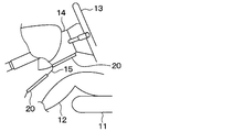
- the heater device 20 is installed indoors so as to radiate radiant heat to the feet of the occupant 12.
- the heater device 20 can be used as a device for immediately providing warmth to the occupant 12 immediately after the activation of another heating device, for example.
- the heater device 20 is installed on the wall surface in the room.
- the heater device 20 is installed so as to face the occupant 12 in an assumed normal posture.
- the road vehicle has a steering column 14 for supporting the steering wheel 13.
- the heater device 20 is installed on the lower surface of the steering column 14 and the lower surface of the column cover 15 so as to face the occupant 12, respectively.
- the heater device 20 includes a heat generating portion 22, an insulating base material 23, a capacitance sensor portion 25, an insulating layer 230, a heater control device 28, and a contact detection control device 29. .
- the heater device 20 is configured as a radiant heater having a structure in which when an object comes into contact with the capacitance sensor unit 25, the temperature of the contacted portion is rapidly lowered. There is.
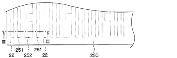
- the heat generating portion 22, the transmitting electrode 251, and the receiving electrode 252 are formed by pattern printing on the surface of the insulating base material 23 on the occupant side.
- the heat generating portion 22, the transmitting electrode 251, and the receiving electrode 252 of the present embodiment are arranged on one surface of the insulating base material 23.
- the insulating base material 23 is made of an insulating resin formed in a substantially rectangular thin plate shape.
- the heat generating part 22 generates heat when energized. By generating heat, the heat generating part 22 can radiate radiant heat that makes the occupant 12 feel warm.
- Each heat generating portion 22 is made of a material having high thermal conductivity.
- the heat generating part 22 can be made of a metal material.
- Each heat generating portion 22 is selected from materials having a thermal conductivity lower than that of copper.
- each heat generating portion 22 can be configured using a metal such as copper, an alloy of copper and tin (Cu—Sn), silver, tin, stainless steel, nickel, or nichrome, and an alloy containing these.
- the capacitance sensor unit 25 has a transmission electrode 251 and a reception electrode 252.
- the transmitting electrode 251 and the receiving electrode 252 can be made of a metal material having a relatively small electric resistance value.
- a contact detection control device 29 is connected to each of the transmitting electrode 251 and the receiving electrode 252.
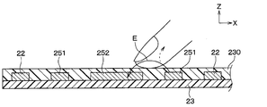
- an electric field is formed between the transmission electrode 251 and the reception electrode 252.
- An arrow E in FIG. 3 represents a line of electric force. Then, when the finger approaches between the transmitting electrode 251 and the receiving electrode 252, a part of the lines of electric force E moves to the finger side, and the electric field received by the receiving electrode 252 decreases.
- the insulating layer 230 has a high insulating property, and is made of, for example, a polyimide film or an insulating resin.
- the heater control device 28 and the contact detection control device 29 are configured as a computer including a CPU, a memory, an I / O, and the like, and the CPU executes various processes according to a program stored in the memory.
- Memory is a non-transitional tangible storage medium.
- the contact detection control device 29 forms an electric field between the transmission electrode 251 and the reception electrode 252, collects the detected value of the electrostatic capacitance between the transmission electrode 251 and the reception electrode 252, and collects the collected electrostatic capacitance.
- the detected value is output to the heater controller 28 as an AD value after analog-digital conversion.
- the heater control device 28 energizes the heat generating portion 22.
- the heater control device 28 determines the contact or non-contact of an object based on the AD value that is output from the contact detection control device 29 and that indicates the detection value of the electrostatic capacitance between the transmission electrode 251 and the reception electrode 252.
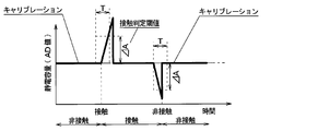
- FIG. 5 is a diagram showing a change in electrostatic capacitance between the transmitting electrode 251 and the receiving electrode 252 when a finger as an object comes into contact with the electrostatic capacitance sensor unit 25 and then the finger becomes non-contact.
- FIG. 5 also shows a state before the fingers are in contact with the capacitance sensor unit 25 and a state in which the fingers are separated from the capacitance sensor unit 25.
- the vertical axis of FIG. 5 is shown as an AD value after analog-digital conversion of the detected value of the electrostatic capacitance between the transmitting electrode 251 and the receiving electrode 252.
- the horizontal axis of FIG. 5 represents the energization time.
- the AD value of the capacitance between the transmission electrode 251 and the reception electrode 252 increases.
- the AD value of the electrostatic capacitance between the transmitting electrode 251 and the receiving electrode 252 is larger than the contact determination threshold value, it is determined that the object is in contact.
- the AD value of the capacitance between the transmission electrode 251 and the reception electrode 252 becomes smaller.
- the AD value of the electrostatic capacitance between the transmitting electrode 251 and the receiving electrode 252 becomes equal to or less than the contact determination threshold value, it is determined that the object is not in contact.
- FIG. 6 is a diagram showing changes in the temperature and the capacitance of the heat generating portion 22 with respect to the energization time in the heaters A to C having the same lot and the same shape.
- the conventional heater device has a problem that it cannot determine that the finger touches the capacitance sensor unit 25.
- FIG. 8 shows the amount of change caused by a temperature change of the capacitance based on the temperature detected by the thermistor, and excludes the amount of change from the detected value of the capacitance, as in the device described in Patent Document 1. Then, an example is shown in which the presence / absence of a finger contact is determined based on the excluded detection value.
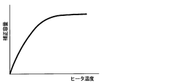
- This apparatus obtains a correction capacity corresponding to a detected temperature value by referring to a correspondence table in which a heater temperature and a correction capacity corresponding to the heater temperature are associated with each other as shown in FIG.
- the presence / absence of finger contact is determined based on the magnitude relationship between the difference value with the capacitance detection value and the threshold value.
- the heater having a characteristic close to the characteristics of the correspondence table can determine the correction capacity corresponding to the detected temperature value by referring to the correspondence table, and determine the presence / absence of contact with a finger.
- the heater device configured to reduce the heater output when detecting the contact of a finger
- the heater temperature decreases and the correction capacity gradually increases as shown in FIG. Therefore, even if the fingers are not in contact with each other thereafter, the AD value indicating the correction capacity does not fall below the contact determination threshold value, and there is a problem that the contact is erroneously determined as non-contact although the fingers are not in contact. is there.
- the heater device of the present embodiment determines that the change in the capacitance between the transmitting electrode 251 and the receiving electrode 252 per predetermined unit time T is an increase of the determination threshold ⁇ A or more. In this case, the process of determining the contact of the object is performed. Further, when the heater device of the present embodiment determines that the change in the capacitance between the transmission electrode 251 and the reception electrode 252 per predetermined unit time T is a decrease of the determination threshold ⁇ A or more, the heater device does not contact the object. Perform the determination process.
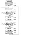
- FIG. 13 shows a flowchart of this process.
- the flowchart shown in FIG. 12 shows the processing of the heater control device 28 and the contact detection control device 29.
- the processing of the heater control device 28 and the contact detection control device 29 will be described as the processing of the control devices 28 and 29.
- the control devices 28 and 29 carry out the processing shown in FIG.
- control devices 28 and 29 start contact detection in S100. Specifically, a predetermined voltage is applied between the transmitting electrode 251 and the receiving electrode 252. As a result, an electric field is formed between the transmitting electrode 251 and the receiving electrode 252.
- control devices 28 and 29 start driving the heater in S102. Specifically, energization of the heat generating portion 22 is started. As a result, the temperature of the heat generating portion 22 rises. Then, the heat generating portion 22 generates heat at a predetermined radiation temperature, and thereby radiates radiant heat that makes the occupant 12 feel warm.
- the control devices 28 and 29 correct the AD value indicating the electrostatic capacitance between the transmitting electrode 251 and the receiving electrode 252 to a reference value for a predetermined period.
- the AD value indicating the capacitance is corrected to 0.
- the AD value indicating the electrostatic capacitance is corrected to 0 at every predetermined time interval Ts. That is, the process of setting the AD value indicating the capacitance between the transmitting electrode 251 and the receiving electrode 252 to 0 and storing it in the memory is repeatedly performed.
- the condition is that the magnitude of change in capacitance between the transmitting electrode 251 and the receiving electrode 252 is less than a predetermined reference value Cb that is smaller than the determination threshold ⁇ A.
- the predetermined time interval Ts is a very short time interval as compared with the reference step T corresponding to the predetermined reference time.
- the magnitude of the change in capacitance between the transmitting electrode 251 and the receiving electrode 252 at the predetermined time interval Ts is equal to or greater than the calibration upper limit Cb, there is a possibility that an object is in contact with the object or the object is not in contact.
- the capacitance is not corrected.
- the magnitude of the change in capacitance between the transmission electrode 251 and the reception electrode 252 at the predetermined time interval Ts is less than the calibration lower limit ⁇ Cb, there is a possibility that the object will contact or the object will not contact. No capacitance correction is performed.
- the control devices 28 and 29 determine in S106 whether or not the change in the capacitance between the transmitting electrode 251 and the receiving electrode 252 in the reference step T is an increase of the determination threshold ⁇ A or more.
- the difference between the detected value of the electrostatic capacitance between the transmitting electrode 251 and the receiving electrode 252 and the detected value of the electrostatic capacitance between the transmitting electrode 251 and the receiving electrode 252 before the reference step T is the determination threshold value. It is determined whether the increase is ⁇ A or more.
- the AD value indicating the capacitance between the transmitting electrode 251 and the receiving electrode 252 is corrected to the reference value after the reference step T
- the value between the transmitting electrode 251 and the receiving electrode 252 corresponding to the correction value is corrected. It is determined whether or not the amount of change in capacitance is an increase of a determination threshold ⁇ A or more.
- the reference step T corresponds to a predetermined unit time.
- the determination threshold ⁇ A is a positive value.
- the control device 28 , 29 returns to the step of S104 without determining that the object has touched.
- the control devices 28 and 29 are , S108, it is determined that the object has come into contact. Then, in S110, the heater output is reduced. Specifically, the energization amount of the heat generating portion 22 is reduced.
- control devices 28 and 29 determine in S112 whether or not the change in the capacitance between the transmission electrode 251 and the reception electrode 252 in the reference step T is a decrease of the determination threshold ⁇ A or more. Specifically, the difference between the detected value of the electrostatic capacitance between the transmitting electrode 251 and the receiving electrode 252 and the detected value of the electrostatic capacitance between the transmitting electrode 251 and the receiving electrode 252 before the reference step T is the determination threshold value. It is determined whether the decrease is ⁇ A or more.
- the control devices 28 and 29 cause the control devices 28 and 29 to S108.
- the heater output is increased. Specifically, the amount of electricity supplied to the heat generating portion 22 is increased so as to reach the amount of electricity before being reduced.
- the control devices 28 and 29 correct the AD value indicating the capacitance between the transmission electrode 251 and the reception electrode 252 to a reference value for a predetermined period that is set in advance.
- the AD value indicating the capacitance is corrected to 0.
- the process of repeatedly setting the AD value indicating the electrostatic capacitance between the transmitting electrode 251 and the receiving electrode 252 to 0 and storing it in the memory is repeatedly performed at predetermined time intervals Ts, and then proceeds to S104.
- the condition is that the magnitude of change in capacitance between the transmitting electrode 251 and the receiving electrode 252 is less than a predetermined reference value Cb that is smaller than the determination threshold ⁇ A.
- the capacitance between the transmitting electrode 251 and the receiving electrode 252 decreases, and when the object separates from the capacitance sensor unit 25, the transmitting electrode 251 In some cases, the capacitance between the receiving electrode 252 and the receiving electrode 252 may increase.
- the contact of the object is determined. Then, when it is determined that the change in the capacitance between the transmission electrode 251 and the reception electrode 252 per predetermined unit time T is a change in the one direction or more that is equal to or more than the second determination threshold value, the non-contact of the object is determined. You can also do it.
- the heater device according to the present embodiment has a structure in which when an object contacts the capacitance sensor unit 25, the temperature of the contacted portion is rapidly lowered, and the temperature of the contacted portion for several seconds to several tens of seconds is thermal. Since the occupant does not feel uncomfortable, the time lag for contact determination does not matter.
- the heater device has the heating portion 22 arranged on the insulating base material 23 and the plurality of electrodes arranged on the insulating base material 23 for detecting contact or non-contact of an object. 251 and 252 are provided. Further, a contact determination unit that determines contact or non-contact of an object based on a change in electrostatic capacitance between the plurality of electrodes 251 and 252 is provided. In addition, the contact determination unit determines the contact of the object when it is determined that the change in capacitance between the plurality of electrodes 251 and 252 per predetermined unit time T is a change in one direction equal to or greater than the determination threshold.
- the change in the capacitance between the plurality of electrodes 251 and 252 per predetermined unit time is a change that is equal to or larger than the determination threshold value in one direction and the opposite direction, it is determined that the object is not in contact.
- the contact determination unit determines that the change in the capacitance between the plurality of electrodes 251 and 252 per predetermined unit time T is a change in one direction equal to or greater than the first determination threshold value. , Determine the contact of objects. Furthermore, when the contact determination unit determines that the change in the capacitance between the plurality of electrodes 251 and 252 per predetermined unit time T is the change in the one direction or the opposite direction of the second determination threshold value or more, Determine non-contact. Therefore, it is possible to more accurately determine contact or non-contact while suppressing the influence of temperature change.
- the heater device of the present embodiment also includes a first correction unit (S104) that corrects the electrostatic capacitance between the plurality of electrodes 251 and 252 to a reference value.
- the first correction unit determines whether the change in capacitance between the plurality of electrodes 251 and 252 per predetermined unit time T is a one-way change that is less than the first determination threshold value, when the contact determination unit determines that the change is one-way.
- the capacitance is corrected to the reference value at every predetermined time interval Ts shorter than the unit time T.
- the condition is that the magnitude of the detected value of the electrostatic capacitance between the plurality of electrodes 251 and 252 is less than a predetermined reference value smaller than the smaller one of the first determination threshold value and the second determination threshold value.
- the contact determination unit determines the change in the capacitance between the plurality of electrodes 251 and 252 per predetermined unit time T from the capacitance between the plurality of electrodes with respect to the reference value corrected by the first correction unit. It is specified as the amount of change.
- the heater device of the present embodiment also includes a second correction unit (S118) that corrects the capacitance between the plurality of electrodes to the reference value.
- the second correction unit determines whether or not the change in capacitance between the plurality of electrodes per predetermined unit time is determined by the contact determination unit to be a change in a direction opposite to the second determination threshold value in the opposite direction.
- the capacitance between the plurality of electrodes is corrected to a reference value at predetermined time intervals (Ts) shorter than the time.
- Ts time intervals
- the contact determination unit specifies the change in the capacitance between the plurality of electrodes per predetermined unit time as the amount of change in the capacitance between the plurality of electrodes with respect to the reference value corrected by the second correction unit. To do.
- the heater device of the present embodiment includes an energization amount lowering unit that lowers the energization amount to the heat generating unit 22 when the contact determination unit determines that the object contacts.
- a heater device according to the second embodiment will be described with reference to FIGS. 15 to 16.
- the heater device of this embodiment has the same configuration as the heater device of the first embodiment.
- the heater device of the present embodiment is different from the heater device of the first embodiment in the processing of the control devices 28 and 29.
- control devices 28 and 29 of this embodiment are different from the control devices 28 and 29 of the first embodiment described above in that the process of step S111 is performed after YES is determined in S106 of FIG. .
- the controller 28, 29 determines YES in S106 and reduces the heater output in S110, in S111, the capacitance between the transmitting electrode 251 and the receiving electrode 252 is reduced for a predetermined period.
- the AD value shown is corrected to the reference value.
- the AD value indicating the electrostatic capacitance is corrected to 0.
- the control devices 28 and 29 repeatedly perform a process of setting the AD value indicating the capacitance between the transmission electrode 251 and the reception electrode 252 to 0 and storing the AD value in the memory at predetermined time intervals Ts.
- the condition is that the magnitude of change in capacitance between the transmitting electrode 251 and the receiving electrode 252 is less than a predetermined reference value Cb that is smaller than the determination threshold ⁇ A.
- the predetermined time interval Ts is a very short time interval as compared with the reference step T corresponding to the predetermined reference time.
- control devices 28 and 29 determine in S112 whether or not the change in the capacitance between the transmission electrode 251 and the reception electrode 252 in the reference step T is a decrease of the determination threshold ⁇ A or more. Specifically, the difference between the detected value of the electrostatic capacitance between the transmitting electrode 251 and the receiving electrode 252 and the detected value of the electrostatic capacitance between the transmitting electrode 251 and the receiving electrode 252 before the reference step T is the determination threshold value. It is determined whether the decrease is ⁇ A or more.
- the process returns to S111. If the change in the capacitance between the transmitting electrode 251 and the receiving electrode 252 in the reference step T is a decrease of the determination threshold ⁇ A or more, the process proceeds to S114.
- the heater control device 28 and the contact detection control device 29 are configured as a computer including a CPU, a memory, an I / O, etc., but the heater control device 28 and the contact detection device are not necessarily such computers. It is not necessary to configure the controller 29.
- the present disclosure is not limited to the above-described embodiment, and can be modified as appropriate. Further, the above embodiments are not unrelated to each other, and can be appropriately combined unless a combination is obviously impossible. Further, in each of the above-described embodiments, it is needless to say that the elements constituting the embodiment are not necessarily essential unless explicitly specified as being essential or in principle considered to be essential. Yes. Further, in each of the above-mentioned embodiments, when numerical values such as the number of components, numerical values, amounts, ranges, etc. of the embodiments are mentioned, it is clearly limited to a particular number and in principle limited to a specific number. The number is not limited to the specific number, except in the case of being performed.
- the heater device is disposed in the insulating base material and the heat generating portion arranged in the insulating base material, and makes contact or non-contact of an object.
- a plurality of electrodes for detection is provided.
- a contact determination unit that determines contact or non-contact of an object based on a change in electrostatic capacitance between the plurality of electrodes is provided. Then, the contact determination unit determines the contact of the object when it is determined that the change in the capacitance between the plurality of electrodes per predetermined unit time is a change in one direction equal to or more than the first determination threshold.
- the contact determination unit determines non-contact of the object when it determines that the change in the capacitance between the plurality of electrodes per predetermined unit time is a change that is equal to or greater than the second determination threshold value in one direction and the opposite direction. To do.
- the heater device includes the first correction unit that corrects the electrostatic capacitance between the plurality of electrodes to the reference value.
- the first correction unit is shorter than the predetermined unit time when the contact determination unit determines that the change in capacitance between the plurality of electrodes per predetermined unit time is a change in one direction that is less than the first determination threshold.
- the capacitance between the plurality of electrodes is corrected to a reference value at predetermined time intervals.
- the condition is that the magnitude of the detected capacitance value between the plurality of electrodes is less than a predetermined reference value that is smaller than the smaller one of the first determination threshold value and the second determination threshold value.
- the contact determination unit specifies the change in the capacitance between the plurality of electrodes per predetermined unit time as the amount of change in the capacitance between the plurality of electrodes with respect to the reference value corrected by the first correction unit. To do.
- the heater device includes a second correction unit that corrects the electrostatic capacitance between the plurality of electrodes to a reference value.
- the second correction unit determines whether or not the change in capacitance between the plurality of electrodes per predetermined unit time is determined by the contact determination unit to be a change in a direction opposite to the second determination threshold value in the opposite direction.
- the capacitance between the plurality of electrodes is corrected to a reference value at predetermined time intervals shorter than the time.
- the condition is that the magnitude of the detected capacitance value between the plurality of electrodes is less than a predetermined reference value that is smaller than the smaller one of the first determination threshold value and the second determination threshold value.
- the contact determination unit specifies the change in the capacitance between the plurality of electrodes per predetermined unit time as the amount of change in the capacitance between the plurality of electrodes with respect to the reference value corrected by the second correction unit. To do.
- the power supply amount lowering unit that lowers the power supply amount to the heat generating unit 22 is provided.
- S106, S108, S112, and S114 correspond to the contact determination unit
- S104 corresponds to the first correction unit
- S118 corresponds to the second correction unit
- S110 corresponds to the power reduction unit.
Landscapes
- Engineering & Computer Science (AREA)
- Physics & Mathematics (AREA)
- General Engineering & Computer Science (AREA)
- Theoretical Computer Science (AREA)
- Thermal Sciences (AREA)
- Mechanical Engineering (AREA)
- Human Computer Interaction (AREA)
- General Physics & Mathematics (AREA)
- Control Of Resistance Heating (AREA)
- Electric Stoves And Ranges (AREA)
Priority Applications (1)
| Application Number | Priority Date | Filing Date | Title |
|---|---|---|---|
| US17/209,734 US12122216B2 (en) | 2018-10-09 | 2021-03-23 | Heater device |
Applications Claiming Priority (2)
| Application Number | Priority Date | Filing Date | Title |
|---|---|---|---|
| JP2018191138A JP7077905B2 (ja) | 2018-10-09 | 2018-10-09 | ヒータ装置 |
| JP2018-191138 | 2018-10-09 |
Related Child Applications (1)
| Application Number | Title | Priority Date | Filing Date |
|---|---|---|---|
| US17/209,734 Continuation US12122216B2 (en) | 2018-10-09 | 2021-03-23 | Heater device |
Publications (1)
| Publication Number | Publication Date |
|---|---|
| WO2020075473A1 true WO2020075473A1 (ja) | 2020-04-16 |
Family
ID=70164261
Family Applications (1)
| Application Number | Title | Priority Date | Filing Date |
|---|---|---|---|
| PCT/JP2019/036774 Ceased WO2020075473A1 (ja) | 2018-10-09 | 2019-09-19 | ヒータ装置 |
Country Status (3)
| Country | Link |
|---|---|
| US (1) | US12122216B2 (https=) |
| JP (1) | JP7077905B2 (https=) |
| WO (1) | WO2020075473A1 (https=) |
Families Citing this family (5)
| Publication number | Priority date | Publication date | Assignee | Title |
|---|---|---|---|---|
| JP2020199988A (ja) * | 2019-06-13 | 2020-12-17 | トヨタ自動車株式会社 | 車両の暖房装置 |
| KR102708368B1 (ko) * | 2019-09-16 | 2024-09-20 | 엘지전자 주식회사 | 차량 공조 제어 장치 및 방법 |
| FR3127448B1 (fr) | 2021-09-30 | 2024-09-06 | Faurecia Sieges Dautomobile | Procédé de traitement de données et ensemble d’un siège et d’un contrôleur |
| JP7627677B2 (ja) * | 2022-12-02 | 2025-02-06 | 本田技研工業株式会社 | ステアリング装置 |
| JP7605807B2 (ja) * | 2022-12-02 | 2024-12-24 | 本田技研工業株式会社 | ステアリング装置 |
Citations (4)
| Publication number | Priority date | Publication date | Assignee | Title |
|---|---|---|---|---|
| JP2010234852A (ja) * | 2009-03-30 | 2010-10-21 | Aisin Seiki Co Ltd | 車両用ヘッドレスト装置 |
| JP2015210800A (ja) * | 2014-04-30 | 2015-11-24 | シャープ株式会社 | 情報処理装置、及び情報処理装置の制御方法 |
| JP2016100662A (ja) * | 2014-11-19 | 2016-05-30 | アイシン精機株式会社 | 車両用操作検出装置 |
| JP2018133289A (ja) * | 2017-02-17 | 2018-08-23 | 株式会社デンソー | ヒータ装置 |
Family Cites Families (8)
| Publication number | Priority date | Publication date | Assignee | Title |
|---|---|---|---|---|
| JPH06104317B2 (ja) | 1991-11-13 | 1994-12-21 | 株式会社コルテック | ロール状長尺物の切断装置 |
| JPH06347355A (ja) | 1993-06-10 | 1994-12-22 | Toyota Motor Corp | 圧電センサの出力補正方法 |
| JP3972064B2 (ja) | 1999-04-02 | 2007-09-05 | 独立行政法人労働安全衛生総合研究所 | センサ装置及び安全装置 |
| JP5352905B2 (ja) * | 2009-05-28 | 2013-11-27 | ルネサスエレクトロニクス株式会社 | 半導体装置およびそれを用いたタッチセンサ |
| JP5533558B2 (ja) * | 2010-10-28 | 2014-06-25 | セイコーエプソン株式会社 | 入力装置 |
| JP5519487B2 (ja) | 2010-12-28 | 2014-06-11 | 小島プレス工業株式会社 | スイッチ装置および車室用照明装置 |
| JP5954235B2 (ja) | 2013-03-28 | 2016-07-20 | 株式会社デンソー | ヒータ装置 |
| DE112016001738T5 (de) * | 2015-04-15 | 2017-12-21 | Denso Corporation | Heizervorrichtung |
-
2018
- 2018-10-09 JP JP2018191138A patent/JP7077905B2/ja active Active
-
2019
- 2019-09-19 WO PCT/JP2019/036774 patent/WO2020075473A1/ja not_active Ceased
-
2021
- 2021-03-23 US US17/209,734 patent/US12122216B2/en active Active
Patent Citations (4)
| Publication number | Priority date | Publication date | Assignee | Title |
|---|---|---|---|---|
| JP2010234852A (ja) * | 2009-03-30 | 2010-10-21 | Aisin Seiki Co Ltd | 車両用ヘッドレスト装置 |
| JP2015210800A (ja) * | 2014-04-30 | 2015-11-24 | シャープ株式会社 | 情報処理装置、及び情報処理装置の制御方法 |
| JP2016100662A (ja) * | 2014-11-19 | 2016-05-30 | アイシン精機株式会社 | 車両用操作検出装置 |
| JP2018133289A (ja) * | 2017-02-17 | 2018-08-23 | 株式会社デンソー | ヒータ装置 |
Also Published As
| Publication number | Publication date |
|---|---|
| US12122216B2 (en) | 2024-10-22 |
| JP2020060313A (ja) | 2020-04-16 |
| JP7077905B2 (ja) | 2022-05-31 |
| US20210206230A1 (en) | 2021-07-08 |
Similar Documents
| Publication | Publication Date | Title |
|---|---|---|
| WO2020075473A1 (ja) | ヒータ装置 | |
| CN106576399B (zh) | 辐射加热器装置 | |
| JP6288310B2 (ja) | ヒータ装置 | |
| JP6376286B2 (ja) | ヒータ装置 | |
| CN105075390B (zh) | 加热器装置 | |
| CN111886147B (zh) | 加热器装置 | |
| JP5549872B2 (ja) | ヒーティングシステム | |
| US11497084B2 (en) | Heater device | |
| US12365218B2 (en) | Heater device | |
| JP6432691B2 (ja) | ヒータ装置 | |
| CN113613531A (zh) | 加热器装置 | |
| US12331937B2 (en) | Heater device | |
| JP6863387B2 (ja) | 輻射ヒータ装置 | |
| JP6432696B2 (ja) | ヒータ装置 | |
| JP2021106117A (ja) | ヒータ装置 | |
| JP7035812B2 (ja) | ヒータ装置 |
Legal Events
| Date | Code | Title | Description |
|---|---|---|---|
| 121 | Ep: the epo has been informed by wipo that ep was designated in this application |
Ref document number: 19870480 Country of ref document: EP Kind code of ref document: A1 |
|
| NENP | Non-entry into the national phase |
Ref country code: DE |
|
| 122 | Ep: pct application non-entry in european phase |
Ref document number: 19870480 Country of ref document: EP Kind code of ref document: A1 |