WO2020071202A1 - 車両用窓ガラス、及びその製造方法 - Google Patents
車両用窓ガラス、及びその製造方法Info
- Publication number
- WO2020071202A1 WO2020071202A1 PCT/JP2019/037559 JP2019037559W WO2020071202A1 WO 2020071202 A1 WO2020071202 A1 WO 2020071202A1 JP 2019037559 W JP2019037559 W JP 2019037559W WO 2020071202 A1 WO2020071202 A1 WO 2020071202A1
- Authority
- WO
- WIPO (PCT)
- Prior art keywords
- coating
- liquid
- film
- colored
- window glass
- Prior art date
- Legal status (The legal status is an assumption and is not a legal conclusion. Google has not performed a legal analysis and makes no representation as to the accuracy of the status listed.)
- Ceased
Links
Images




Classifications
-
- B—PERFORMING OPERATIONS; TRANSPORTING
- B60—VEHICLES IN GENERAL
- B60J—WINDOWS, WINDSCREENS, NON-FIXED ROOFS, DOORS, OR SIMILAR DEVICES FOR VEHICLES; REMOVABLE EXTERNAL PROTECTIVE COVERINGS SPECIALLY ADAPTED FOR VEHICLES
- B60J1/00—Windows; Windscreens; Accessories therefor
-
- C—CHEMISTRY; METALLURGY
- C03—GLASS; MINERAL OR SLAG WOOL
- C03C—CHEMICAL COMPOSITION OF GLASSES, GLAZES OR VITREOUS ENAMELS; SURFACE TREATMENT OF GLASS; SURFACE TREATMENT OF FIBRES OR FILAMENTS MADE FROM GLASS, MINERALS OR SLAGS; JOINING GLASS TO GLASS OR OTHER MATERIALS
- C03C17/00—Surface treatment of glass, not in the form of fibres or filaments, by coating
- C03C17/34—Surface treatment of glass, not in the form of fibres or filaments, by coating with at least two coatings having different compositions
Definitions
- the present disclosure relates to a vehicle window glass having a colored film formed thereon and a method for manufacturing the same.
- Patent Literatures 1 and 2 disclose that, in a vehicle window glass having a dark color coating, a portion where the high mount stop lamp is arranged is a region without the dark color coating.
- Patent Document 1 discloses that a dark-colored film is not formed on a light-emitting light-transmitting portion, or is removed after the dark-colored film is formed, or a film having higher visible light transmittance than the dark-colored film is formed. Discloses that the visible light transmittance of a light emitting light transmitting portion is higher than that of a dark color portion.
- Patent Document 2 discloses a method in which after forming a dark-colored film on the entire surface of a glass by a spray method or the like, the portion is removed by sandblasting to form the portion having high visible light transmittance.
- a coating having a different color (including colorless as a type of color) for each part of the window glass (hereinafter, may be referred to as a “multicolor coating” in this specification).
- a multicolor coating in this specification.
- various coating methods can be mentioned, but the film formation by the spray method becomes efficient.
- the spray method is an application method in which mist is sprayed onto the substrate, it is necessary to avoid the mist being scattered in areas other than the application target area and forming droplets of the application liquid on the main surface of the glass plate. Can't pass.
- the components of a coating solution for forming a coating are adjusted so that the coating and the glass can adhere to each other. For this reason, the droplets formed outside the application target site adhere to the surface of the glass plate, and a point-like adhered component is formed on the surface of the glass plate. Since the vehicle window glass on which the colored coating is formed is a visible light transmitting article, a point-like fixing component can be visually recognized.
- Patent Document 1 discloses a method of forming a coating having a higher visible light transmittance than a dark-colored coating on a light-emitting light transmitting portion.
- spray method there is no specific disclosure about the spray method, and dot-like fixation in the spray method is not disclosed. The problem of the ingredients has not been recognized.
- the present disclosure is a glass plate on which a colored coating is formed, and a glass plate in which a coating having higher visible light transmittance than the colored coating is formed on a part of the glass plate by a spray method.
- Vehicle window glass of the present disclosure A curved glass plate with a main surface, On the main surface, a first coating portion made of a first colored coating, and a second colored coating or a colorless coating having a higher visible light transmittance than the first colored coating adjacent to the first coating portion.
- a window glass for a vehicle comprising: The coating of the first coating portion and the second coating portion is formed by applying and drying a first coating solution for forming the first coating portion and a second coating solution for forming the second coating portion. It is a film integrated with a uniform film thickness, Between the first coating portion and the second coating portion, a visible light transmittance from the first coating portion formed by mixing the first coating solution and the second coating solution to the second coating portion. Has a gradually changing boundary.
- the point-like fixing component is hard to be visually recognized.
- the first coating portion and the second coating portion integrally with a uniform film thickness, optical distortion at the boundary can be reduced.
- the boundary between the first coating portion and the second coating portion is such that the visible light transmittance gradually changes from the first coating portion to the second coating portion so that the boundary portion is conspicuous. And improve the appearance quality of the multicolor coating.
- the second colored coating having a higher visible light transmittance than the first colored coating is based on the visible light transmittance required by a high-mount stop lamp or various in-vehicle cameras.
- the visible light transmittance of the second colored coating may be higher than that of the first colored coating by 5% or more, preferably 20% or more.
- Both the first colored film and the second colored film have the same pigment, and it is preferable that the coloring of the film is caused by the pigment.
- a colorless film is a film having a small change in color tone of the glass plate due to the film, and a colorless film having an absorbance per 1 ⁇ m thickness of 0.20 or less in a wavelength range of 380 nm to 780 nm.
- the colorless coating is preferably defined as a colorless film, preferably 0.10 or less.
- the absorbance can be obtained from the following equation.
- First manufacturing method The manufacturing method of the vehicle window glass of the present disclosure (first manufacturing method), A curved glass plate having a main surface, on the main surface, a first coating portion made of a first colored coating, adjacent to the first coating portion, the visible light transmittance is higher than the first colored coating.
- a method for manufacturing a window glass for a vehicle comprising a second colored film or a second film portion made of a colorless film, A step (1) of preparing a first coating solution for forming a first coating portion and a second coating solution for forming a second coating portion; (2a) preparing a liquid film of the first coating liquid by spraying the mist of the first coating liquid on a portion where the first coating portion is to be formed by spraying the first coating liquid; (2b) preparing a liquid film of the second coating liquid by spraying the mist of the second coating liquid on a portion where the second coating portion is to be formed by spraying the second coating liquid; (3) drying and curing each liquid film, In the step (2b), before the droplets of the first coating liquid formed at the portions where the second coating portion is to be formed by the mist of the first coating liquid in the step (2a) are dried, A mist of the second coating liquid is sprayed to form a boundary portion composed of a mixed liquid film of the liquid film of the first coating liquid and the liquid film of the
- the manufacturing method (second manufacturing method) of the vehicle window glass of the present disclosure includes: A curved glass plate having a main surface, on the main surface, a first coating portion made of a first colored coating, adjacent to the first coating portion, the visible light transmittance is higher than the first colored coating.
- a method for manufacturing a window glass for a vehicle comprising a second colored film or a second film portion made of a colorless film, A step (1) of preparing a first coating solution for forming a first coating portion and a second coating solution for forming a second coating portion; (2c) preparing a liquid film of the second coating liquid by spraying the mist of the second coating liquid on a portion where the second coating portion is to be formed by spraying the second coating liquid; A step (2d) of spraying the mist of the first coating liquid on the portion where the first coating portion is to be formed by spraying the first coating liquid to prepare a liquid film of the first coating liquid; (3) drying and curing each liquid film, In the step (2d), before the droplet of the second coating liquid formed at the place where the first coating portion is to be formed by the mist of the second coating liquid in the step (2c) dries, A mist of the first coating liquid is sprayed to form a boundary portion composed of a mixed liquid film of the liquid film of the second coating liquid and the liquid film
- the coating liquid is applied to a glass plate by a spray method.
- the spray method is a method suitable for applying a coating solution onto the entire main surface of a glass plate with good discharge efficiency.
- a component adhering to the mist scattered at a place where a film of another color is to be formed Is important.
- the coating for forming the other color coating on the location is performed.
- the visible light transmittance is adjusted to a preferable value, and the appearance quality is improved, and a multicolor coating is formed.
- a window glass for a vehicle is provided.
- an integrated film having a uniform thickness is formed between the first coating portion and the second coating portion, and the visible light transmittance gradually changes from the first coating portion to the second coating portion. Forming a border that reduces the optical distortion reduces optical distortion, makes the border less noticeable, and improves the appearance quality of the multicolor coating.
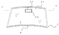
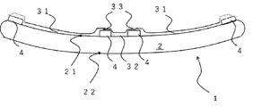
- FIG. 1 is a schematic front view of an example of a vehicle window glass of the present disclosure as viewed from the outside of a vehicle.
- FIG. 2 is a diagram schematically illustrating a cross-sectional shape taken along the line a-a ′ illustrated in FIG. 1.
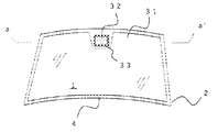
- FIG. 2 is a schematic front view of a vehicle window glass according to another embodiment different from FIG. 1.
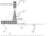
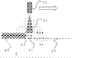
- 1 is a diagram schematically illustrating a first method for manufacturing a vehicle window glass of the present disclosure. It is a figure which illustrates typically the state at the time of apply
- FIG. 2 is a schematic front view of a derivative of the vehicle window glass shown in FIG. 1.
- FIG. 9 is a diagram schematically showing a cross-sectional shape taken along the line a-a ′ shown in FIG. 8.
- FIG. 1 is a schematic front view of an example of the vehicle window glass of the present disclosure as viewed from the outside of the vehicle
- FIG. 2 is a diagram schematically illustrating a cross-sectional shape taken along the line a-a ′ illustrated in FIG.
- the first coating portion 31 and the second coating portion 32 are formed on the concave main surface 21 of the glass plate 2, but may be formed on the convex main surface 22.
- the vehicle window glass 1 shown in FIGS. 1 and 2 has a curved glass plate 2 having a concave main surface 21 and a convex main surface 22, and a first colored coating on the concave main surface 21.
- a first coating portion 31 and a second coating portion 32 made of a second colored coating or a colorless coating having a higher visible light transmittance than the first colored coating are provided.
- the first coating portion 31 and the second coating portion 32 form an integrated coating with a uniform thickness.
- the vehicle window glass 1 has a boundary between the first coating portion 31 and the second coating portion 32 where the visible light transmittance gradually changes from the first coating portion 31 to the second coating portion 32. It has a part 33.
- the vehicle window glass 1 has the first coating portion 31 and the second coating portion 32, that is, has a multicolor coating.
- a glass plate having a shape suitable for a window of a vehicle such as an automobile is used, and a glass plate having a shape such as a trapezoid or a rectangle can be used.
- a plate glass generally used for vehicles such as automobiles and manufactured by a float method or the like can be used.
- the end face of the glass plate 2 may be processed into an R shape by polishing.
- the thickness of the glass plate 2 is not particularly limited, but the main surfaces 21 and 22 of the glass are parallel, for example, those having a thickness of 0.3 to 15 mm and those having a thickness of 0.5 to 5 mm. And those having a thickness of 1 to 3 mm can be used. It is preferable that the glass plate 2 has an absorbance of 0.10 or less, preferably 0.02 or less, per 1 mm in a wavelength range of 380 nm to 780 nm. This type of glass plate is a glass plate that is seen almost colorless when viewed from the main surfaces 21 and 22, and can reflect the color of the first coating portion 31 itself on the vehicle window glass 1.
- the glass plate 2 may include a visible light shielding layer 4.
- the visible light shielding layer 4 is formed on the periphery of the glass plate 2 and may have a thickness of, for example, 8 ⁇ m to 20 ⁇ m.
- the first coating portion 31 may be formed on the visible light shielding layer 4.
- the visible light shielding layer 4 is, for example, a strip-shaped decorative body made of a black ceramic shielding film or the like, and can be formed of a general-purpose material.
- a ceramic paste is applied on the main surface of the glass plate 2, preferably on the concave main surface 21 by screen printing, and after a drying step and a firing step, the visible light shielding layer 4 made of a color ceramic such as black ceramic is formed. It is formed.
- the visible light shielding layer 4 is provided between the first coating portion 31 and the main surface, preferably the first coating. It is preferably between the portion 31 and the concave-side main surface 21.
- the main surface of the glass plate 2 is cleaned and dried before the first coating portion 31, the second coating portion 32, and the boundary portion 33 are formed.
- a cleaning example a known cleaning method such as cleaning using an abrasive such as cerium oxide, brush cleaning, a shower, and a high-pressure shower can be used.
- a drying a known drying method such as natural drying or an air shower can be used. Dry cleaning using atmospheric pressure plasma or UV ozone may be used.
- the first coating portion 31 and the second coating portion 32 are adjacent via a boundary portion 33, and the first coating portion 31, the second coating portion 32, A completed film is formed in which the portion 33 and the uniform thickness are integrated.
- a boundary portion 33 where the visible light transmittance gradually changes from the first coating portion 31 to the second coating portion 32 is formed.
- the concentration of the coloring component of the first colored film forming the first coated portion 31 is gradually reduced toward the second coated portion 32 because the concentration of the coloring component is reduced by the second coating liquid.
- the second coating portion 32 is formed of a second colored coating or a colorless coating having higher visible light transmittance than the first colored coating forming the first coating portion, the first coating portion 31 is formed at the boundary 33. , The visible light transmittance gradually changes from the second coating portion 32 to the second coating portion 32.
- the integrated film having a uniform thickness is formed, so that from the first film portion 31 to the second film portion 32, there is little discomfort to human eyes.
- a multicolor coating having good appearance quality can be obtained.
- the thickness is preferably 1.5 ⁇ m to 8 ⁇ m. If the thickness is less than 1.5 ⁇ m, the coloring property of the coating deteriorates, so that it is necessary to increase the content of the pigment in order to maintain the coloring property. As a result, the durability of the coating tends to be inferior. It is easy to get worse.
- the thickness of the finished film may be more preferably 2 ⁇ m to 7 ⁇ m, and further preferably 2.5 ⁇ m to 6 ⁇ m. Further, the width of the boundary portion 33 may be set to 10 mm to 40 mm from the viewpoint of ease of manufacturing and appearance quality.
- the base material forming the coating is the same. That is, it is preferable that the difference between the components is that the types and contents of the coloring components are different. With such a configuration, the first coating portion 31, the boundary portion 33, and the second coating portion 32 can easily form an integrated film having a uniform thickness.
- the second coating 32 may be surrounded by the boundary 33, and the boundary 33 may be surrounded by the first coating 31.
- the second coating portion 32 having a higher visible light transmittance than the first coating portion 31 is used to emit light from a high-mount stop lamp, incident light to various sensors, and light from communication devices. It can be a window through which emission light, incident light to a vehicle-mounted camera, and the like pass.
- the visible light shielding layer 4 protrudes from the center of the upper side to the lower side from the center of the band-shaped portion arranged at the peripheral edge.
- a blank portion of the visible light shielding layer 4 where the light shielding layer 4 is not formed is provided.
- the second coating portion 32 may be formed in the blank portion, and the boundary portion 33 may be provided on the protruding portion of the visible light shielding layer 4 as shown in FIG.
- the first coating portion 31 and the second coating portion 32 may also be provided on the site.
- the formation of the boundary portion 33 on the visible light shielding layer 4 contributes to the efficiency of the quality inspection of the window glass for vehicles. can do.
- the vehicle window glass 1 may have a structure in which a first coating portion 31 and a second coating portion 32 are vertically divided via a boundary portion 33. Further, the vehicle window glass 1 may have a structure in which the first coating portion 31 and the second coating portion 32 are divided right and left through the boundary portion 33 (not shown).
- the base material forming the coating of the first coating 31, the second coating 32, and the boundary 33 be made of the same material as described above.
- the base material is preferably made of a condensate of a metal alkoxide.
- the first colored film, the second colored film, and the colorless film are formed from a coating solution containing a metal alkoxide and / or a condensate of a metal alkoxide.
- B metal alkoxides and / or condensates of metal alkoxides
- F a pigment; Can be used.
- (C) a synthetic resin in addition to the above (a), (b) and (f), (C) a synthetic resin; (D) a triazine-based ultraviolet absorber having an SP value of 10 to 13.5 (cal / cm 3 ) 1/2 ; (E) a solvent consisting of a non-aqueous solvent having an SP value of substantially 8 to 11.5 (cal / cm 3 ) 1/2 ; May be added to form a first coating solution.
- the second coating liquid (A) for forming the second coating portion composed of the second colored coating In (a) R 1 4-n Si (OR 2) n [1] silane compound containing an amino group represented by formula ([1], R 1 represents an organic group containing an amino group, R 2 is Represents a methyl group, an ethyl group or a propyl group, and n represents an integer selected from 1 to 3); A reaction product obtained by reacting at least one boron compound selected from the group consisting of H 3 BO 3 and B 2 O 3 ; (B) metal alkoxides and / or condensates of metal alkoxides; (F) a pigment; Can be used.
- (C) a synthetic resin in addition to the above (a), (b) and (f), (C) a synthetic resin; (D) a triazine-based ultraviolet absorber having an SP value of 10 to 13.5 (cal / cm 3 ) 1/2 ; (E) a solvent consisting of a non-aqueous solvent having an SP value of substantially 8 to 11.5 (cal / cm 3 ) 1/2 ; May be added to form the second coating liquid (A).
- the second coating liquid (B) for forming the second coating portion composed of a colorless coating In (a) R 1 4-n Si (OR 2) n [1] silane compound containing an amino group represented by formula ([1], R 1 represents an organic group containing an amino group, R 2 is Represents a methyl group, an ethyl group or a propyl group, and n represents an integer selected from 1 to 3); A reaction product obtained by reacting at least one boron compound selected from the group consisting of H 3 BO 3 and B 2 O 3 ; (B) metal alkoxides and / or condensates of metal alkoxides; Can be used.
- each of the coating liquids contains the ultraviolet absorber
- the coating liquid contains 5 to 12% by mass of the ultraviolet absorber with respect to the total solid content.
- the “total solids” refers to the total amount of the components constituting the coating, and the amount is determined from the total amount of the components excluding the solvent from the coating solution, by hydrolysis or polycondensation reaction, etc. It can be determined by reducing the amount of the organic group to be eliminated. Since the viscosity of the coating solution is also affected by the amount of the total solids in the coating solution for forming a film, it can be set in consideration of the coating efficiency of each coating solution on a glass plate. %, Preferably 10% to 35% by mass.
- n represents an integer selected from 1 to 3
- boron compound selected from the group consisting of H 3 BO 3 and B 2 O 3 is mixed, these components react to form a transparent and viscous liquid in several minutes to several tens minutes and solidifies.
- the boron compound acts as a cross-linking agent via the amino group in the silane compound containing an amino group, and polymerizes these components. As a result, it is considered that a viscous liquid is formed and solidified.
- the silane compound containing an amino group is a liquid. In the reaction between the silane compound containing an amino group and the boron compound, it is preferable not to use water.
- R 1 represents an organic group containing an amino group.
- ⁇ -aminopropyl (also referred to as 3-aminopropyl) and aminoethylaminopropyl are particularly preferred, and ⁇ -aminopropyl is most preferred.
- R 2 represents a methyl group, an ethyl group or a propyl group. Among them, a methyl group and an ethyl group are preferred.
- N represents an integer selected from 1 to 3.
- n is preferably 2 or 3, and n is particularly preferably 3. That is, as the silane compound containing an amino group, ⁇ -aminopropyltriethoxysilane and N- ⁇ - (aminoethyl) - ⁇ -aminopropyltrimethoxysilane are particularly preferable.
- the boron compound is at least one boron compound selected from the group consisting of H 3 BO 3 and B 2 O 3 .
- H 3 BO 3 is particularly preferred.
- the amount of both components used in the reaction between the silane compound containing an amino group and the boron compound is preferably such that the boron compound is used in an amount of 0.1 mol based on 1 mol of the silane compound containing an amino group in consideration of the reaction rate.
- the ratio is from 02 mol to 8 mol, more preferably from 0.02 mol to 5 mol, even more preferably from 0.2 mol to 5 mol.
- the mixing conditions (temperature, mixing time, mixing method, etc.) of the silane compound containing an amino group and the boron compound can be appropriately selected. Under normal room temperature conditions, it becomes a transparent and viscous liquid in several minutes to several tens minutes and solidifies. The time for solidification and the viscosity and stiffness of the resulting reaction product differ depending on the proportion of the boron compound. Note that a viscous liquid is more preferable than a solidified liquid because it is easily converted into a component that is stably dissolved in the coating liquid.
- the reaction product is preferably a reaction product obtained by reacting the boron compound with the silane compound containing an amino group without passing through a step of adding water and hydrolyzing.
- the amount of the reaction product can be 40% by mass to 80% by mass based on the total solid content. If the amount is less than 40% by mass, the hardness of the obtained coating film may be low. On the other hand, if the content is more than 80% by mass, cracks may occur in the obtained coating during the weather resistance test. In consideration of these, the amount of the reaction product may be 50% by mass to 70% by mass based on the total solid content.
- ⁇ About component (b)> A metal alkoxide and / or a condensate of a metal alkoxide are added to the reaction product as the component (b). That is, the component (b) is added during or after the reaction between the silane compound containing an amino group and the boron compound. By adding the component (b), the hardness of the obtained coating film can be improved, and a viscous liquid state similar to the case where the component (b) is not used is obtained. And dissolved components.
- Examples of the metal of the metal alkoxide of the component (b) include Si, Ta, Nb, Ti, Zr, Al, Ge, B, Na, Ga, Ce, V, Ta, P, and Sb. It is not limited to these. Preferably, they are Si, Ti, and Zr. Since the component (b) is preferably a liquid, Si and Ti are particularly preferable.
- Examples of the alkoxide (alkoxy group) of the metal alkoxide of the component (b) include a methoxy group, an ethoxy group, a propoxy group, a butoxy group, and an alkoxy group having a higher carbon number.
- a methoxy group, an ethoxy group, a propoxy group, and a butoxy group are preferred, and a methoxy group and an ethoxy group are more preferred.
- Particularly preferred components (b) include tetramethoxysilane and tetraethoxysilane.
- the metal alkoxide of the component (b) include tetramethoxysilane, tetraethoxysilane, tetrapropoxysilane, tetrabutoxysilane, methyltrimethoxysilane, ethyltriethoxysilane, propyltripropoxysilane, butyltributoxysilane, and tetrabutylsilane.
- the amount of the metal alkoxide used as the component (b) is preferably 10 mol or less based on 1 mol of the amino group-containing silane compound or 1 mol of the boron compound. More preferably, the ratio is 0.1 mol to 5 mol. If the amount of the component (b) is less than 0.1 mol relative to 1 mol of the silane compound containing an amino group or 1 mol of the boron compound, the effect of adding the component (b) as described above may not be easily obtained. If the amount of the component (b) is more than 5 mol, cloudiness may occur.
- Examples of the condensate of the metal alkoxide of the component (b) include a condensate of a metal alkoxide represented by at least one formula selected from the group consisting of the following formulas (b1) and (b2).
- R 3 represents an alkyl group, a part of which may be hydrogen, R 3 may be each independently the same or different, and m is selected from 2 to 20.
- M represents at least one metal selected from the group consisting of Si, Ti and Zr.
- the addition amount of the condensate of the metal alkoxide as the component (b) is preferably 2 to 50 mol, preferably 4 mol or more, in terms of the mass of the metal alkoxide monomer, per 1 mol of the silane compound containing an amino group. More preferably, there is.
- the amount of the component (b) is too large, the hardness of the obtained film tends to decrease.
- the amount is too small, the content of the metal element is small, so that the film obtained depending on the application is not used. Hardness may decrease or chemical durability problems may occur. If the amount of the component (b) is too large, the curing time for obtaining the coating of the present disclosure tends to be long.
- R 3 in the condensate of the metal alkoxide as the component (b) represents an alkyl group, a part of which may be hydrogen, and R 3 may be independently the same or different.
- R 3 is a methyl group, an ethyl group, a propyl group, a butyl group, or an alkyl group having more carbon atoms, and is preferably a methyl group or an ethyl group.
- m in the condensate of the metal alkoxide as the component (b) represents an integer selected from 2 to 20, but is preferably 3 to 10, and most preferably 5.
- M in the condensate of the metal alkoxide as the component (b) represents at least one metal selected from the group consisting of Si, Ti and Zr, and is preferably Si or Ti, Si is most preferred.
- metal alkoxide monomer unit constituting the condensate of the metal alkoxide as the component (b)
- tetramethoxysilane, tetraethoxysilane, tetrapropoxysilane, tetrabutoxysilane methyltrimethoxysilane, ethyltriethoxysilane, propyltripropylsilane Propoxysilane, butyltributoxysilane, tetramethoxytitanium, tetraethoxytitanium, tetrapropoxytitanium, tetrabutoxytitanium, methyltrimethoxytitanium, ethyltriethoxytitanium, propyltripropoxytitanium, butyltributoxytitanium, tetramethoxyzirconium, tetraethoxy Zirconium, tetrapropoxyzirconium, tetrabutoxy
- the component (b) is represented by the formula (b1), it is preferably a condensate of tetraethoxysilane (pentamer) or a condensate of tetramethoxysilane (pentamer).
- it is preferably a condensate of ethyltriethoxysilane (pentamer) or a condensate of methyltrimethoxysilane (pentamer).
- a metal alkoxide (monomer) and / or a condensate of a metal alkoxide are added to the reaction product of the present disclosure as the component (b). Since the viscosity of the metal alkoxide monomer is lower than that of the condensate, the addition of the metal alkoxide monomer may improve the coating properties of the resulting coating solution. When the amount is more than the same amount as the condensate, the viscosity of the coating liquid is apt to decrease, and the liquid is liable to be dripped when applied.
- the synthetic resin (c) is preferably added to the reaction product. That is, during or after the reaction between the silane compound containing an amino group and the boron compound, a synthetic resin is added as the component (c). By adding the component (c), the resulting coating film can be provided with anti-cracking properties.
- the synthetic resin as the component (c) is not particularly limited, and examples thereof include a thermosetting resin, a thermoplastic resin, and an ultraviolet curable resin.
- an acrylic resin, an epoxy resin, a polyester resin examples thereof include amino resins, urethane resins, furan resins, silicone resins, and modified products of these resins, and synthetic resins having various degrees of polymerization (molecular weight) can be used.
- epoxy resin, dipentaerythritol hexaacrylate, epoxy acrylate, silicone resin, vinyl ester resin, polyvinyl butyral, polyvinyl alcohol and the like are preferable.
- the form of the synthetic resin is preferably liquid.
- the amount of the component (c) used is preferably 5 to 30% by mass based on the total solid content. More preferably, the ratio is 10 to 20% by mass.
- the amount of the component (c) is less than 5% by mass, the effect of adding the component (c) as described above may be difficult to be obtained, and when the amount of the component (c) exceeds 30% by mass, a resin curing agent may be used. In some cases, and it may not be possible to impart high hardness to the resulting coating.
- a triazine-based ultraviolet absorber having an SP value of 10 to 13.5 (cal / cm 3 ) 1/2 is used.
- a triazine-based ultraviolet absorber having an SP value of 10 to 13.5 (cal / cm 3 ) 1/2 is used.
- BASF's TINUVIN 400 SP value: 11.0 (cal / cm 3 ) 1/2
- TINUVIN 460 SP value: 10.9 (cal / cm 3 ) 1/2
- TINUVIN 479 SP value: 11.3) (Cal / cm 3 ) 1/2
- TINUVIN 477 SP value: 11.4 (cal / cm 3 ) 1/2 .
- the reason why good results can be obtained with a triazine-based ultraviolet absorber is not clear, but it is considered that the absorber has a high ultraviolet absorbing ability and good weather resistance.
- the component (e) serves as a solvent in each coating solution, and is substantially composed of a non-aqueous solvent having an SP value of 8 to 11.5 (cal / cm 3 ) 1/2 .
- Non-aqueous solvent having an SP value of substantially 8 to 11.5 (cal / cm 3 ) 1/2 means "a non-aqueous solvent having an SP value of 8 to 11.5 (cal / cm 3 ) 1/2" .
- a solvent in which the SP value of the mixed solvent falls within the range of 8 to 11.5 (cal / cm 3 ) 1/2 ”.
- the SP value of the mixed solvent can be calculated from the following formula when, for example, two types of “solvent A” and “solvent B” are used.
- the ultraviolet absorbent used in the present disclosure can be uniformly dispersed in the coating solution.
- the ultraviolet absorber can be uniformly dispersed in the resulting coating. If the SP value of the solvent is less than 8, the ultraviolet absorbent may precipitate from the coating film after application, and the finally obtained coating film may be opaque.
- the solvent contained in the coating liquid of the present disclosure is substantially composed of a non-aqueous solvent having an SP value of 8 to 10.5 (cal / cm 3 ) 1/2 , the resulting coating liquid is obtained. Since the leveling property of the liquid is improved, it is preferable that the leveling of the coating film be completed in a shorter time when the leveling step described below is performed.
- non-aqueous solvent having an SP value of 8 to 11.5 (cal / cm 3 ) 1/2 for example, aromatic hydrocarbons such as toluene (SP value: 9.1 (cal / cm 3 ) 1/2 ), Xylene (SP value: 9.1 (cal / cm 3 ) 1/2 ), ethyl acetate of acetates (SP value: 8.8 (cal / cm 3 ) 1/2 ), butyl acetate (SP value) : 8.7 (cal / cm 3 ) 1/2 ), acetone of ketones (SP value: 9.1 (cal / cm 3 ) 1/2 ), methyl ethyl ketone (SP value: 9.0 (cal / cm 3 )) ) 1/2 ), methyl isobutyl ketone (SP value: 8.3 (cal / cm 3 ) 1/2 ), cyclohexanone (SP value: 9.8 (cal / cm 3 ) 1/2 ), 2-heptanone ( SP value: 8.5 (cal / cm 3 )
- Methyl isobutyl ketone (SP value: 8.3 (cal / cm 3 ) 1/2 ), cyclohexanone (SP value: 9.8 (cal / cm 3 ) 1/2 ), 2-heptanone (SP value: 8. 5 (cal / cm 3 ) 1/2 ) and glycol ethers such as 3-methoxy-3-methylbutanol (SP value: 10.5 (cal / cm 3 ) 1/2 ), 1-methoxy-2-propanol ( SP value 11.3 (cal / cm 3) 1/2 ), 1- ethoxy-2-propanol (SP value: 10.9 (cal / cm 3) 1/2) is preferred.
- each coating solution may contain a solvent having an SP value other than 8 to 11.5 (cal / cm 3 ) 1/2 .
- SP Value 8 to 11.5 (cal / cm 3 ) 1/2 .
- n-hexane SP Value: 7.3 (cal / cm 3 ) 1/2
- diethyl ether SP value: 7.3 (cal / cm 3 ) 1/2
- 2-methoxyethanol SP value: 12.0 (cal / cm 3 )) cm 3 ) 1/2
- carbon tetrachloride SP value: 12.2 (cal / cm 3 ) 1/2 ).
- each coating solution contains, in addition to the component (e), It may contain other solvents such as water, alcohols, ketones and the like.
- the pigment of the component (f) is selected according to the color of the first colored film.
- a blue pigment for example, Pigment Blue 15, Pigment Blue 28, cesium tungsten oxide (CWO) fine particles
- CWO cesium tungsten oxide
- a green pigment for example, Pigment Green 36, Pigment Green 56
- a yellow pigment for example, Pigment Yellow 150, Pigment Yellow, e.g.
- the black pigment include Pigment Black 26, and examples of the pink pigment include Pigment Red 202, Pigment Violet 19, and the like.
- the average particle diameter D 50 of the pigment is preferably 10 ⁇ 300 nm. If D 50 is less than 10 nm, there is aggregation prone, for 300nm exceeds tend to visible light transmittance is deteriorated.
- the average particle diameter D 50 of the pigment 15 ⁇ 280 nm, more preferably in the 20 ⁇ 250 nm.
- the D 50 is in the particle size distribution obtained by measuring the volume distribution in water by dynamic scattering method particle of the pigment is that of cumulative 50% particle diameter.
- the pigment can be contained in the first coating liquid in an amount of 0.02 to 0.50 times by mass the ultraviolet absorber of the component (d). If it is less than 0.02 times, the color development of the first colored film tends to deteriorate, and if it exceeds 0.50 times, the haze tends to increase. In consideration of these, the pigment is preferably contained in the first coating solution in a mass ratio of 0.025 to 0.45 times, more preferably 0.03 to 0.36 times, of the ultraviolet absorber.
- the second coating liquid (A) contains a pigment, and its content is adjusted to be lower than the visible light transmittance of the first colored film. When the second coating liquid (A) contains the ultraviolet absorbent of the component (d), the second coating liquid (A) may be contained in a mass ratio of less than 0.02 times the ultraviolet absorbent.
- Each of the coating liquids may include fine particles made of a conductive substance.
- the fine particles made of a conductive substance By containing the fine particles made of a conductive substance, the colored coated glass sheet can be provided with infrared shielding properties.
- the conductive material include ITO (indium tin oxide) and ATO (antimony tin oxide).
- the content may as comprising 5-15% by weight based on the total solids, an average particle diameter D 50 may use one of 50 ⁇ 100 nm.
- each of the coating liquids may contain, in addition to the above components, an antifungal agent, a photocatalytic material, a rust inhibitor, an anticorrosive, an alga inhibitor, a water repellent, an oil repellent, a light stabilizer, an oxidant, depending on the use.
- an antifungal agent e.g., a photocatalytic material, a rust inhibitor, an anticorrosive, an alga inhibitor, a water repellent, an oil repellent, a light stabilizer, an oxidant, depending on the use.
- An inhibitor, a substrate wetting agent, a hydrophilic material, a water absorbing material, and the like may be included.
- the vehicle window glass 1 shown in FIGS. 1 and 2 can be manufactured by applying the coating liquid to the concave main surface 21 or the convex main surface 22 of the curved glass plate 2.
- the first manufacturing method of the vehicle window glass 1 includes: A curved glass plate 2 having a main surface (concave main surface 21 and convex main surface 22), and a first colored film formed on the main surface (concave main surface 21 or convex main surface 22) of a first colored film.
- a method for manufacturing a vehicle window glass 1 including one coating portion 31 and a second coating portion 32 made of a second colored coating or a colorless coating having a higher visible light transmittance than the first colored coating A step (1) of preparing the first coating liquid and the second coating liquid ((A) or (B)); A step (2a) of spraying the first coating solution by spraying the mist 51 of the first coating solution on a portion where the first coating portion 31 is to be formed, thereby preparing a liquid film 61 of the first coating solution;
- the mist 52 of the second coating liquid is sprayed on a portion where the second coating portion 32 is to be formed, and the liquid film 62 of the second coating liquid and the first coating liquid are sprayed.
- FIG. 4 is a diagram schematically illustrating the first manufacturing method.
- a first coating liquid is sprayed from a first spray nozzle 81 to prepare a liquid film 61 of the first coating liquid to be the first coating part 31.
- FIG. 5 shows that after forming the liquid film 61 by the first spray nozzle 81, the second coating liquid is sprayed from the second spray nozzle 82 to form the liquid film 62 of the second coating liquid and the liquid film 61 and the liquid film 62.
- This is a schematic representation of the state when the mixed liquid film 63 is formed.
- the spray nozzles 81 and 82 spray the coating liquid from the tip of the spray nozzle while moving, for example, in the directions of arrows in FIGS. 4 and 5, apply the coating liquid to the glass plate 2, and apply the coating liquid. A liquid film of liquid is formed.
- the liquid film 62 is formed adjacent to the edge of the liquid film 61 while the fluidity of the liquid film 61 is maintained.
- the films 61 and 62 are mixed.
- the edge becomes the mixed liquid film 63.
- the difference between the thickness of the first coating portion 31 and the thickness of the second coating portion 32 is preferably small.
- the thickness of the second coating 32 are preferably in the range of 0.80 to 1.20, more preferably 0.95 to 1.05.
- the spray nozzles 81 and 82 two spray nozzles may be used.
- the first and second coating liquids are discharged from one spray nozzle by operating a valve of a pipe through which the first coating liquid flows, and the first and second coating liquids are switched.
- the spray nozzle when the first coating liquid is discharged may be the spray nozzle 81, and the spray nozzle when the second coating liquid is discharged may be the spray nozzle 82.
- the second manufacturing method of the vehicle window glass 1 includes: A curved glass plate 2 having a main surface (concave main surface 21 and convex main surface 22), and a first colored film formed on the main surface (concave main surface 21 or convex main surface 22) of a first colored film.
- a method for manufacturing a window glass for a vehicle comprising one coating portion 31 and a second coating portion 32 made of a second colored coating or a colorless coating having a higher visible light transmittance than the first colored coating, A step (1) of preparing a first coating solution for forming a first coating portion and a second coating solution ((A) or (B)) for forming a second coating portion; A step (2c) of spraying the mist 52 of the second coating liquid on the portion where the second coating portion 32 is to be formed by spraying the second coating liquid to prepare a liquid film 62 of the second coating liquid.
- the first coating liquid is sprayed by spraying a mist 51 of the first coating liquid on a portion where the first coating portion 31 is to be formed, so that the liquid film 61 of the first coating liquid and the second coating liquid (2d) preparing the liquid film 61 of the first coating liquid so that the liquid film 62 is integrated with the liquid film 61 to form a mixed liquid film 63 of the liquid film 61 and the liquid film 62; (3) drying and curing each liquid film, In the step (2d), before the droplet 72 of the second coating liquid formed at the place where the first coating portion is to be formed by the mist 52 of the second coating liquid in the step (2c) is dried. Then, a mist 51 of the first coating liquid is sprayed to prepare a liquid film 61 of the first coating liquid.
- FIG. 6 is a diagram schematically illustrating the second manufacturing method, in which a second coating liquid is sprayed from a second spray nozzle 82 to prepare a liquid film 62 of the second coating liquid to be the second coating part 32.
- FIG. 7 shows that after the liquid film 62 is formed by the second spray nozzle 82, the first coating liquid is sprayed from the first spray nozzle 81 to form the liquid film 61 of the first coating liquid and the liquid film 61 and the liquid film 62.
- This is a schematic representation of the state when the mixed liquid film 63 is formed.
- the spray nozzles 81 and 82 spray the coating liquid from the tip of the spray nozzle while moving, for example, in the directions of arrows in FIGS. 6 and 7, apply the coating liquid to the glass plate 2, and apply the coating liquid. A liquid film of liquid is formed.
- the spray nozzles 81 and 82 may use two spray nozzles. Further, in one spray nozzle, the first and second coating liquids are discharged from one spray nozzle by a valve operation of a pipe through which the first coating liquid flows, and the first and second coating liquids are switched.
- the spray nozzle when the first coating liquid is discharged may be the spray nozzle 81, and the spray nozzle when the second coating liquid is discharged may be the spray nozzle 82.
- the first manufacturing method and the second manufacturing method are the same except that the order of applying the first coating liquid to the glass plate 2 and the second coating liquid are different.
- the droplets 71 and 72 disappear, so that poor appearance of the coating caused by the droplets 71 and 72 can be suppressed. Since the total amount of the droplets 71 and 72 is very small relative to the total amount of the film, there is almost no effect on the formed film, and the color of the film is not visually affected.
- the mist sprayed from the spray nozzle is an aggregate of droplets of the coating liquid.
- the size of the droplet may be 1 ⁇ m ⁇ to 500 ⁇ m ⁇ when the droplet is considered to be spherical.
- the size of the droplet can be adjusted according to the pressure condition of the spray nozzle, the viscosity of the coating liquid, and the like.
- the state of the droplets 71, 72 formed based on the mist changes depending on the distance from the edge (edge) of the liquid films 61, 62.
- the shapes of the droplets 71 and 72 are various, and there are many hemispherical objects away from the edges of the liquid films 61 and 62. As the edges approach the edges, the spheres are randomly connected and exhibit an irregular shape. Become.
- the liquid film 62 is formed including the droplet 71 before the droplet 71 dries, even when the liquid 71 is formed, even the droplet 71 is dried. Therefore, the liquid film 61 remains in a liquid state. Therefore, a mixed liquid film 63 of the liquid film 61 and the liquid film 62 is formed in the boundary region between the liquid film 61 and the liquid film 62.
- the liquid film 61 is formed including the droplet 72 before the droplet 72 is dried, even when the liquid 72 is formed, even the droplet 72 is formed. Since it has not been dried, the liquid film 62 remains in a liquid state. Therefore, a mixed liquid film 63 of the liquid film 61 and the liquid film 62 is formed in the boundary region between the liquid film 61 and the liquid film 62.
- the application amounts of the respective coating liquids are adjusted, and the liquid films 61, 62, and the mixed liquid film 63 are formed.
- the glass plate 2 is allowed to stand still, that is, a leveling step is performed so as to form a proper liquid surface state.
- the leveling step is preferably performed at room temperature for 5 to 20 minutes.
- ultrasonic vibration may be applied to the glass plate 2 to promote the formation of a uniform liquid surface state in each liquid film.
- a drying step of evaporating the solvent in each liquid film is performed. This drying step may be performed by heating the glass plate 2 on which the liquid film is formed at 20 ° C. to 300 ° C., or may be allowed to stand at room temperature to dry. Then, the coating film (a liquid film in which the solvent is evaporated is referred to as a coating film) is cured by exposing it to heat of 100 to 350 ° C. and water vapor, and the first coating portion 31 is formed on the main surface of the glass plate 2. , A second coating portion 32 and a boundary portion 33 are formed.
- the curing step In order to stabilize the temperature of the glass plate 2 and the amount of water vapor brought into contact with the coating film, it is preferable to perform the curing step in a chamber. Exposure of the glass plate 2 on which the coating film is formed to superheated steam at a temperature of more than 100 ° C. to 350 ° C. is more preferable because a dehydration condensation reaction proceeds in a short time and a high-hardness coating film is obtained. More preferred temperature of the superheated steam is more than 100 ° C to 300 ° C.
- the superheated steam is steam having a temperature of more than 100 ° C. obtained by further heating saturated steam of 100 ° C.
- vehicle window glass of the present disclosure will be described in Examples and Comparative Examples.
- Example 1 Step of preparing a first coating liquid and a second coating liquid ⁇ Preparation of first coating liquid (coating liquid for first coating unit 31)>
- a reaction vessel 1.61 g of boric acid (H 3 BO 3 ) powder as a component (a-2) was added to 9.72 g of a 3-aminopropyltriethoxysilane solution as a component (a-1) ((( (a-2) was added at a ratio of 0.6 mol to 1 mol of the component (a-1)) and stirred at 23 ° C.
- H 3 BO 3 boric acid
- component (b) (A) is added so that component (b) is present in a ratio of 2.6 moles per mole of component (a-1).
- component (c) 5.08 g of Nagase ChemteX epoxy resin CY232 (total solids) After addition, the mixture was reacted at 60 ° C. for 120 hours to form a viscous liquid.
- TINUVIN 477 SP value: 11.4 (cal / cm 3 ) 1/2
- TINUVIN 292 as a light stabilizer 0.47 g
- Shin-Etsu Silicone as a surface conditioner 0.68 g of KP-301
- 0.50 g of a pigment dispersion solid content: 10%, carbon black was used as a black pigment
- the SP value of the solvent contained in the coating solution is 9.0 (cal / cm 3 ) 1/2 .
- the prepared coating liquid was colored and transparent. No cloudiness due to aggregation or the like was observed, and the ultraviolet absorber and carbon black were uniformly dispersed in the coating solution.
- Second coating solution (coating solution for second coating portion 32)>
- the UV absorber, light stabilizer, conductive material, and pigment dispersion used in the first coating solution were omitted, and the other components were the same. Then, the amounts of the respective components were adjusted so that the solid content concentration was 21% by mass, which was the same as the first coating liquid, and this was used as the second coating liquid.
- the size of the glass plate 2 was 1200 mm (horizontal direction) ⁇ 500 mm (vertical direction) and had three-dimensional bending.
- the peripheral portion of the concave main surface 21 of the glass plate is formed of black ceramic paste and has a width of 40 mm (partly, a portion having a width of 110 mm in the central region of the upper side).
- a band-shaped visible light shielding layer (black ceramic) 4 having a thickness of 12.5 ⁇ m is disposed.
- the concave main surface 21 is formed of a silver paste and has a width of 0.45 mm and a thickness of 10 ⁇ m. Are arranged at intervals of 31 mm.
- the concave main surface 21 is obtained by polishing with ceria powder, washing with water, and drying immediately before the first coating liquid and the second coating liquid are applied.
- the formation part of the second coating part 32 assumes the installation of a high-mount stop lamp, starts from the edge of the visible light shielding layer 4 on the upper side of the glass plate 2, and is 50 mm in length on the center side of the transparent portion of the glass plate 2. It was set so as to be a rectangle having a width of 250 mm.
- a bell cup rotary atomizing air spray gun (Asahi Sunac, ASG200) attached to the robot tip is used.
- the rotational speed of the bell cup was set to 20,000 rpm
- the wide shape air was set to 0.05 MPa
- the short shape air was set to 0.10 MPa.
- Step of preparing a liquid film of the first coating liquid ⁇ dispersion of mist of the first coating liquid>
- the glass plate 2 was allowed to stand substantially horizontally, with the concave main surface 21 facing upward and the convex main surface 22 facing the ground. While keeping the distance between the tip of the spray nozzle 81 and the concave-side main surface 21 at 85 mm, while scanning the spray nozzle 81 on the concave-side main surface 21 by computer control, from the tip of the spray nozzle 81 A mist 51 of the first coating liquid was sprayed to form a liquid film 61 of the first coating liquid on the concave main surface 21.
- the liquid film 61 of the first coating liquid was formed in other regions except the region where the second coating portion 32 was formed.
- the droplet 71 of the first coating liquid was formed in the second coating liquid coating portion outside the region where the liquid film 61 of the first coating liquid was formed.
- the shape of the droplet 71 was various. When the distance from the edge of the liquid film 61 was 40 mm or more, there were many hemispherical objects, and the radius was 10 ⁇ m to 50 ⁇ m. In the range of 20 to 40 mm from the edge of the liquid film 61, in addition to the hemispherical droplets, the hemispheres were connected at random and formed an irregular shape. The maximum length of the irregularly shaped liquid was about 200 to 500 ⁇ m. In the range of 0 to 20 mm from the edge of the liquid film 61, the irregular shape and the thin film having a thickness of 1.0 ⁇ m were formed. Any one of the above was observed on the entire surface of the second coating liquid application section.
- Step of preparing a liquid film of the second coating solution ⁇ dispersion of mist of the second coating solution> Then, while keeping the distance between the tip of the spray nozzle 82 and the concave-side main surface 21 at 85 mm, the spray nozzle 82 scans on the concave-side main surface 21, and the second from the tip of the spray nozzle 82 A mist 52 of the second coating liquid was sprayed to form a liquid film 62 of the second coating liquid on the remaining portion of the concave-side main surface 21 where the liquid film 61 of the first coating liquid was not formed.
- the mist 52 of the second coating liquid is sprayed before the droplets 71 are dried, and the liquid film 61 of the first coating liquid and the In the boundary region between the two coating liquids and the liquid film 62, the scan width is set so that the two liquid films 61 and 62 are integrated, specifically, so that the film thickness of the mixed liquid film 63 becomes equal to the liquid films 61 and 62. Then, the discharge amount of the second coating liquid and the coating speed were adjusted by computer control, and a mixed liquid film 63 was prepared.
- the conditions for discharging the liquid film 61 of the first coating liquid onto the concave main surface 21 and the conditions for discharging the liquid film 62 of the second coating liquid onto the concave main surface 21 were the same.
- the glass plate 2 on which the liquid film 61 of the first coating liquid and the liquid film 62 of the second coating liquid are formed is placed in a hot air circulating furnace at 180 ° C. For 5 minutes to dry each liquid film. After this heating, the article was exposed to superheated steam at 180 ° C. for 10 minutes. Through the above steps, the vehicle window glass 1 was obtained. In the vehicle window glass 1 of the present embodiment, a boundary portion 33 is formed between the first coating portion 31 and the second coating portion 32.
- the vehicle window glass 1 of this example was evaluated by the following evaluation method. Various evaluation results are shown in Table 1. At the boundary portion 33, the visible light transmittance gradually increased from the first coating portion 31 side to the second coating portion 32 side, and the boundary portion 33 became inconspicuous.
- the film thickness of the coating on the vehicle window glass 1 was measured using a surf coder ET4000A manufactured by Kosaka Laboratory.
- the visible light transmittance of the vehicle window glass 1 was calculated using a spectrophotometer U-4100 manufactured by Hitachi according to JIS R3212 (2015). In the measurement, both the first coating portion 31 and the second coating portion 32 were measured near the center of each coating region. Further, the transmittance of the boundary portion 33 is set in the vertical direction from the edge of the upper side of the visible light shielding layer 4 (at a location of 40 mm width) on the center side of the glass plate 2 so as to match the present embodiment. , 35 mm, 50 mm, and 65 mm. The respective measurement results are described in Table 1 as a boundary 33 (1), a boundary 33 (2), and a boundary 33 (3).
- Comparative Example 1 In the formation of the liquid film 62 of the second coating liquid, the mist 52 of the second coating liquid was sprayed after the droplets 71 were dried. Window glass 1 was obtained. In the vehicle window glass 1 of this comparative example, spot distribution was observed in the second coating portion 32, which is considered to be caused by the droplet 71, which was inappropriate as a visible light transmitting region.
- Comparative Example 2 Except that the application amount of the second coating liquid was reduced so that the film thickness of the second coating part 32 was thinner than that of the first coating part 31, the vehicle window glass 1 was manufactured through the same operation as in Example 1. was gotten. In the vehicle window glass 1 of this comparative example, optical distortion was observed at the boundary portion 33.
Landscapes
- Chemical & Material Sciences (AREA)
- Engineering & Computer Science (AREA)
- Life Sciences & Earth Sciences (AREA)
- Chemical Kinetics & Catalysis (AREA)
- General Chemical & Material Sciences (AREA)
- Geochemistry & Mineralogy (AREA)
- Materials Engineering (AREA)
- Organic Chemistry (AREA)
- Mechanical Engineering (AREA)
- Surface Treatment Of Glass (AREA)
- Application Of Or Painting With Fluid Materials (AREA)
Abstract
本開示の車両用窓ガラスは、主面を備える湾曲したガラス板と、上記主面上に、第一着色被膜からなる第一被膜部と、上記第一被膜部に隣接し、上記第一着色被膜よりも可視光線透過率が高い第二着色被膜又は無色被膜からなる第二被膜部とを備える車両用窓ガラスであって、上記第一被膜部と上記第二被膜部の被膜は、上記第一被膜部を形成するための第一塗布液と上記第二被膜部を形成するための第二塗布液の塗布乾燥によって形成された、一様な膜厚で一体化された被膜であり、上記第一被膜部と上記第二被膜部との間には、上記第一塗布液と上記第二塗布液の混合によって形成された上記第一被膜部から上記第二被膜部にかけて可視光線透過率が徐変する境界部を有する。
Description
本開示は、着色被膜が形成された車両用窓ガラスと、その製造方法に関する。
近年、車両の機能の高度化に伴い、車両には、センサー、通信装置、車載カメラ、ハイマウントストップランプ、映像表示装置などの各種デバイスが搭載されるようになってきている。そのため、車両用窓ガラスには、各種デバイスの機能を利用する、または損なうことがないようにすることが求められている。他方では、意匠性、プライバシー保護、遮熱性等の観点から、可視光線透過率の低い着色被膜が形成された車両用窓ガラスも求められている。このように、各種デバイスの機能発揮と、着色被膜の機能との両立性も問われるようになってきている。
このような観点から、特許文献1及び2では、濃色被膜付きの車両用窓ガラスにおいて、ハイマウントストップランプが配置される部位を、濃色被膜のない領域とすることが開示されている。特に、特許文献1は、発光光線透過部分には、濃色被膜を形成しない、または、濃色被膜形成後に除去する、あるいは、濃色被膜より可視光線透過率の高い被膜を形成する、等によって、発光光線透過部分の可視光線透過率を濃色部分より高くすることを開示している。また、特許文献2は、濃色被膜をガラス全面にスプレー法等で形成した後、前記部位をサンドブラストで除去して可視光線透過率の高い前記部位を形成する方法を開示している。
着色被膜が形成された車両用窓ガラスにおいて、窓ガラスの部位ごとで、色(色の種類として、無色も含む)の異なる被膜(以降、本明細書では「多色被膜」と表記する場合あり)を形成させることは、各種デバイスの機能発揮と、着色被膜の機能との両立性の解決手段となりうる。そして、多色被膜を形成させる方法としては、各種の塗布法が挙げられるが、スプレー法による被膜形成が効率的なものとなる。
しかしながら、スプレー法は、基材に対してミストを散布する塗布方法なので、塗布対象部位以外にもミストが飛散し、ガラス板主面上に塗布液の液滴状物が形成されることは避けては通れない。車両用窓ガラスでは、被膜を形成するための塗布液は、被膜とガラスとが密着することができるように成分が調整されている。そのため、塗布対象部位以外に形成された液滴状物が、ガラス板表面に固着し、ガラス板表面上に点状の固着成分が形成されることになる。着色被膜が形成された車両用窓ガラスは、可視光透過性の物品なので、点状の固着成分が視認されるようになる。
特許文献1は、発光光線透過部分に、濃色被膜より可視光線透過率の高い被膜を形成する方法を開示しているが、スプレー法については具体的開示がなく、スプレー法における点状の固着成分の問題の認識には至っていない。
本開示は、以上を考慮して、着色被膜を形成したガラス板であって、一部の部位に前記着色被膜よりも可視光線透過率の高い被膜をスプレー法によって形成したガラス板の、前記部位に着色被膜の塗布液からなる点状の固着成分が無いようにした車両用窓ガラスと、前記着色被膜と前記部位の両方の被膜をスプレー法によって一体的に形成し、光学歪や外観品質を改善する手段を提供することを課題とする。
本開示の車両用窓ガラスは、
主面を備える湾曲したガラス板と、
前記主面上に、第一着色被膜からなる第一被膜部と、前記第一被膜部に隣接し、前記第一着色被膜よりも可視光線透過率が高い第二着色被膜又は無色被膜からなる第二被膜部とを備える車両用窓ガラスであって、
前記第一被膜部と前記第二被膜部の被膜は、前記第一被膜部を形成するための第一塗布液と前記第二被膜部を形成するための第二塗布液の塗布乾燥によって形成された、一様な膜厚で一体化された被膜であり、
前記第一被膜部と前記第二被膜部との間には、前記第一塗布液と前記第二塗布液の混合によって形成された前記第一被膜部から前記第二被膜部にかけて可視光線透過率が徐変する境界部を有する。
主面を備える湾曲したガラス板と、
前記主面上に、第一着色被膜からなる第一被膜部と、前記第一被膜部に隣接し、前記第一着色被膜よりも可視光線透過率が高い第二着色被膜又は無色被膜からなる第二被膜部とを備える車両用窓ガラスであって、
前記第一被膜部と前記第二被膜部の被膜は、前記第一被膜部を形成するための第一塗布液と前記第二被膜部を形成するための第二塗布液の塗布乾燥によって形成された、一様な膜厚で一体化された被膜であり、
前記第一被膜部と前記第二被膜部との間には、前記第一塗布液と前記第二塗布液の混合によって形成された前記第一被膜部から前記第二被膜部にかけて可視光線透過率が徐変する境界部を有する。
多色被膜を有する車両用窓ガラスの構造を、前記構造とすることで、点状の固着成分が視認され難いものとなる。また、第一被膜部と、第二被膜部とを一様な膜厚で一体化されたものとすることで、前記境界部での光学歪を少なくできる。また、前記第一被膜部と、前記第二被膜部との境界部を、前記第一被膜部から前記第二被膜部にかけて可視光線透過率が徐変するものとすることで、境界部を目立たないようにし、多色被膜の外観品質を改善せしめる。
第二被膜部において、前記第一着色被膜よりも可視光線透過率が高い第二着色被膜とは、ハイマウントストップランプや各種車載カメラで求められる可視光線透過率を基準にしたものである。第二着色被膜の可視光線透過率は、第一着色被膜よりも5%以上、好ましくは20%以上高いものとしてもよい。第一着色被膜、及び第二着色被膜は、双方とも同じ顔料を有し、被膜の着色は、その顔料起因のものとすることが好ましい。また、無色被膜とは、その被膜によって、前記ガラス板の色調の変化が少ないもので、前記無色被膜の、380nm-780nmの波長域において、厚さ1μm当たりの吸光度が、0.20以下のもの、好ましくは0.10以下とせしめるものを無色被膜と定義する。尚、吸光度は、以下の式から求めることができる。
吸光度=Log10(I0/I)=a×L
I0=入射光の強さ
I=透過光の強さ
a=厚さ1μm当たりの吸光度
L=光路長
I0=入射光の強さ
I=透過光の強さ
a=厚さ1μm当たりの吸光度
L=光路長
<第一製造方法>
本開示の車両用窓ガラスの製造方法(第一製造方法)は、
主面を備える湾曲したガラス板と、前記主面上に、第一着色被膜からなる第一被膜部と、前記第一被膜部に隣接し、前記第一着色被膜よりも可視光線透過率が高い第二着色被膜又は無色被膜からなる第二被膜部とを備える車両用窓ガラスの製造方法であって、
第一被膜部形成用の第一塗布液と、第二被膜部形成用の第二塗布液とを準備する工程(1)と、
前記第一塗布液をスプレー法で、前記第一被膜部の形成予定箇所に前記第一塗布液のミストを散布して、前記第一塗布液の液膜を調製する工程(2a)と、
前記第二塗布液をスプレー法で、前記第二被膜部の形成予定箇所に前記第二塗布液のミストを散布して、前記第二塗布液の液膜を調製する工程(2b)と、
各液膜を、乾燥、及び硬化させる工程(3)と、を備え、
前記工程(2b)時において、工程(2a)時に前記第一塗布液のミストによって前記第二被膜部の形成予定箇所に形成された第一塗布液の液滴状物が乾燥する前に、前記第二塗布液のミストを散布して、前記第一塗布液の液膜と前記第二塗布液の液膜との混合液膜からなる境界部を形成し、かつ前記第二塗布液の液膜を調製する。
本開示の車両用窓ガラスの製造方法(第一製造方法)は、
主面を備える湾曲したガラス板と、前記主面上に、第一着色被膜からなる第一被膜部と、前記第一被膜部に隣接し、前記第一着色被膜よりも可視光線透過率が高い第二着色被膜又は無色被膜からなる第二被膜部とを備える車両用窓ガラスの製造方法であって、
第一被膜部形成用の第一塗布液と、第二被膜部形成用の第二塗布液とを準備する工程(1)と、
前記第一塗布液をスプレー法で、前記第一被膜部の形成予定箇所に前記第一塗布液のミストを散布して、前記第一塗布液の液膜を調製する工程(2a)と、
前記第二塗布液をスプレー法で、前記第二被膜部の形成予定箇所に前記第二塗布液のミストを散布して、前記第二塗布液の液膜を調製する工程(2b)と、
各液膜を、乾燥、及び硬化させる工程(3)と、を備え、
前記工程(2b)時において、工程(2a)時に前記第一塗布液のミストによって前記第二被膜部の形成予定箇所に形成された第一塗布液の液滴状物が乾燥する前に、前記第二塗布液のミストを散布して、前記第一塗布液の液膜と前記第二塗布液の液膜との混合液膜からなる境界部を形成し、かつ前記第二塗布液の液膜を調製する。
<第二製造方法>
本開示の車両用窓ガラスの製造方法(第二製造方法)は、
主面を備える湾曲したガラス板と、前記主面上に、第一着色被膜からなる第一被膜部と、前記第一被膜部に隣接し、前記第一着色被膜よりも可視光線透過率が高い第二着色被膜又は無色被膜からなる第二被膜部とを備える車両用窓ガラスの製造方法であって、
第一被膜部形成用の第一塗布液と、第二被膜部形成用の第二塗布液とを準備する工程(1)と、
前記第二塗布液をスプレー法で、前記第二被膜部の形成予定箇所に前記第二塗布液のミストを散布して、前記第二塗布液の液膜を調製する工程(2c)と、
前記第一塗布液をスプレー法で、前記第一被膜部の形成予定箇所に前記第一塗布液のミストを散布して、前記第一塗布液の液膜を調製する工程(2d)と、
各液膜を、乾燥、及び硬化させる工程(3)と、を備え、
前記工程(2d)時において、工程(2c)時に前記第二塗布液のミストによって前記第一被膜部の形成予定箇所に形成された第二塗布液の液滴状物が乾燥する前に、前記第一塗布液のミストを散布して、前記第二塗布液の液膜と前記第一塗布液の液膜との混合液膜からなる境界部を形成し、かつ前記第一塗布液の液膜を調製する。
本開示の車両用窓ガラスの製造方法(第二製造方法)は、
主面を備える湾曲したガラス板と、前記主面上に、第一着色被膜からなる第一被膜部と、前記第一被膜部に隣接し、前記第一着色被膜よりも可視光線透過率が高い第二着色被膜又は無色被膜からなる第二被膜部とを備える車両用窓ガラスの製造方法であって、
第一被膜部形成用の第一塗布液と、第二被膜部形成用の第二塗布液とを準備する工程(1)と、
前記第二塗布液をスプレー法で、前記第二被膜部の形成予定箇所に前記第二塗布液のミストを散布して、前記第二塗布液の液膜を調製する工程(2c)と、
前記第一塗布液をスプレー法で、前記第一被膜部の形成予定箇所に前記第一塗布液のミストを散布して、前記第一塗布液の液膜を調製する工程(2d)と、
各液膜を、乾燥、及び硬化させる工程(3)と、を備え、
前記工程(2d)時において、工程(2c)時に前記第二塗布液のミストによって前記第一被膜部の形成予定箇所に形成された第二塗布液の液滴状物が乾燥する前に、前記第一塗布液のミストを散布して、前記第二塗布液の液膜と前記第一塗布液の液膜との混合液膜からなる境界部を形成し、かつ前記第一塗布液の液膜を調製する。
前記第一製造方法、及び第二製造方法では、塗布液はスプレー法でガラス板に塗布される。スプレー法は、ガラス板の主面全面に塗布液を、吐着効率良く、塗布することに適した方法である。しかしながら、塗布液の塗布時に飛散したミストが、塗布対象領域以外にも塗着されてしまうので、多色被膜の形成においては、他の色の被膜を形成すべき箇所に飛散したミストによる固着成分を、どう解決するかが重要となる。前記第一製造方法、及び第二製造方法では、他の色の被膜を形成すべき箇所に飛散したミストによる固着成分が乾燥する前に、当該箇所に他の色の被膜を形成するための塗布液を塗布することで、そのミストによる固着成分と、該塗布液とをガラス板上で混合させて固着成分を消失させ、その結果、他の色の被膜を外観上、均質なものとせしめる。
本開示により、スプレー法を用いても、可視光線透過領域として不適当な点状の固着成分がなく、可視光線透過率が好ましい値に調整され、外観品質が改善された、多色被膜が形成された車両用窓ガラスが提供される。また、前記第一被膜部と前記第二被膜部とで、一様な膜厚で一体化された被膜を形成し、前記第一被膜部から前記第二被膜部にかけて可視光線透過率が徐変する境界部を形成することは、光学歪を少なくし、境界部を目立たないようにし、多色被膜の外観品質を改善せしめる。
以下、本開示を、図面を用いて説明する。図1は、本開示の車両用窓ガラスの一例を車外側から見た正面概略図であり、図2は、図1で示すa-a’の断面形状を概略的に示す図である。この例では、第一被膜部31と第二被膜部32は、ガラス板2の凹面側主面21上に形成されているが、凸面側主面22上に形成されていてもよい。
図1及び図2に示す車両用窓ガラス1は、凹面側主面21及び凸面側主面22を備える湾曲したガラス板2と、前記凹面側主面21上に、第一着色被膜からなる第一被膜部31と、前記第一着色被膜よりも可視光線透過率が高い第二着色被膜又は無色被膜からなる第二被膜部32とを備える。前記第一被膜部31と前記第二被膜部32とで、一様な膜厚で一体化された被膜が形成されている。前記車両用窓ガラス1は、前記第一被膜部31と前記第二被膜部32との間には、前記第一被膜部31から前記第二被膜部32にかけて可視光線透過率が徐変する境界部33を有する。前記車両用窓ガラス1は、前記第一被膜部31と、前記第二被膜部32とを有するもの、すなわち、多色被膜を有するものである。
前記ガラス板2として、自動車等の車両の窓に適した形状を備えたものが使用され、通常、台形状、矩形状などの形状のものを使用することができる。前記ガラス板2として、自動車等の車両用に汎用されている、フロート法等によって製造された板ガラスを使用することができる。ガラス板2の端面は、研磨によってR形状に加工されていてもよい。
前記ガラス板2の厚みとしては特に制限されるものではないが、ガラスの主面21、22間が平行で、例えば、0.3~15mmの厚みのもの、0.5~5mmの厚みのもの、1~3mmの厚みのものを使用することできる。また、前記ガラス板2は、380nm-780nmの波長域において、厚さ1mm当たりの吸光度が、0.10以下のもの、好ましくは0.02以下のものを使用することが好ましい。この種のガラス板は、主面21、22から観察したときにほぼ無色に見られるガラス板で、前記第一被膜部31のそのものの色味を車両用窓ガラス1に反映させることができる。
また、前記ガラス板2は、可視光遮蔽層4を備えていてもよい。可視光遮蔽層4は、ガラス板2の周縁部に形成され、その厚みは、例えば、8μm~20μmとしてもよい。第一被膜部31は、可視光遮蔽層4上に形成されていてもよい。可視光遮蔽層4は、黒色セラミックの遮蔽膜などからなる、例えば帯状の装飾体であり、汎用の材料で形成することができる。例えば、セラミックペーストが、ガラス板2の主面、好ましくは凹面側主面21上にスクリーン印刷で塗布され、乾燥工程、焼成工程を経て、黒色セラミック等のカラーセラミックからなる可視光遮蔽層4が形成される。ガラス板2が主面直上、好ましくは凹面側主面21直上に可視光遮蔽層4を備える場合、可視光遮蔽層4は、第一被膜部31と主面との間、好ましくは第一被膜部31と凹面側主面21との間にあることが好ましい。
前記ガラス板2の主面は、第一被膜部31、第二被膜部32、境界部33が形成される前に、洗浄により、清浄な状態にされ、さらには乾燥されていることが望ましい。例えば、洗浄例としては、酸化セリウム等の研磨剤を用いた洗浄、ブラシ洗浄、シャワー、高圧シャワー等の公知の洗浄方法を利用することができる。また、前記乾燥としては、自然乾燥、エアシャワー等の公知の乾燥方法を利用することができる。また大気圧プラズマやUVオゾンを用いた乾式の洗浄を用いても良い。
前記第一被膜部31と、前記第二被膜部32とは、図2に示すように、境界部33を介して隣接し、前記第一被膜部31と、前記第二被膜部32と、境界部33とが一様な膜厚で一体化された完成被膜が形成される。前記第一被膜部31と前記第二被膜部32との間には、前記第一被膜部31から前記第二被膜部32にかけて可視光線透過率が徐変する境界部33が形成されている。前記境界部33において、前記第一被膜部31を形成する第一着色被膜の着色成分の濃度は、第二塗布液により薄まるので、前記第二被膜部32に向けて徐々に薄いものとなる。前記第二被膜部32は、前記第一被膜部を形成する第一着色被膜よりも可視光線透過率が高い第二着色被膜又は無色被膜からなるので、境界部33では、前記第一被膜部31から前記第二被膜部32にかけて可視光線透過率が徐変するものとなる。
そして、図2に示すように、一様な膜厚で一体化された完成被膜が形成されるので、第一被膜部31から、第二被膜部32にかけて、人の目には違和感の少ない、外観品質が良好な多色被膜とすることができる。一様な膜厚で一体化された完成被膜において、その厚みは、1.5μm~8μmとすることが好ましい。1.5μm未満では被膜の発色性が悪くなるので、発色性を保つために顔料の含有量を増やす必要があり、結果として被膜の耐久性が劣るものとなりやすく、8μm超では被膜の耐久性が悪くなりやすくなる。これらを考慮すると、完成被膜の厚みは、より好ましくは2μm~7μm、さらに好ましくは2.5μm~6μmとしてもよい。また、前記境界部33の幅は、製造しやすさと、外観品質との観点から、10mm~40mmとしてもよい。
前記第一被膜部31、境界部33、第二被膜部32の各構成において、被膜を形成する母体材料は、同じであることが好ましい。すなわち、各構成の違いは、着色成分の種類や、含有量が異なるものとすることが好ましい。このような構成とすることで、第一被膜部31と、境界部33と、第二被膜部32とで、一様な膜厚で一体化された完成被膜が形成しやすくなる。
また、図1に示すように、第二被膜部32は、境界部33に囲撓され、その境界部33は、第一被膜部31に囲撓されていてもよい。この構造を備える車両用窓ガラス1では、第一被膜部31よりも可視光線透過率の高い第二被膜部32を、ハイマウントストップランプの発光や、各種センサーへの入射光、通信機器からの発射光、車載カメラへの入射光などを通すための窓とすることができる。
また、図1に示された車両用窓ガラス1の派生態様として、図8に示すように、可視光遮蔽層4が、周縁部に配置された帯状の部位の上辺中央から下辺方向に突き出した構造となっているものがある。この突き出した構造部の中には、ハイマウントストップランプの発光や、各種センサーへの入射光、通信機器からの発射光、車載カメラへの入射光などを通すための窓とするために、可視光遮蔽層4が形成されていない可視光遮蔽層4の空白部が設けられる。この空白部に、例えば、前記第二被膜部32を形成し、図9に示すように、境界部33が、可視光遮蔽層4の突き出された部位上に設けられてもよい。第一被膜部31、第二被膜部32も、当該部位上に設けられてもよい。
被膜に可視光線透過率の徐変が生じているかは目視レベルでも判別できるので、前記可視光遮蔽層4上に境界部33が形成されると、車両用窓ガラスの品質検査の効率化に寄与することができる。
さらには、車両用窓ガラス1は、図3に示すような、第一被膜部31と、第二被膜部32とが、境界部33を介して、上下に分割したような構造としてもよい。さらには、車両用窓ガラス1は、第一被膜部31と、第二被膜部32とが、境界部33を介して、左右に分割したような構造としてもよい(図示省略)。
<被膜の母体材料>
第一被膜部31、第二被膜部32、境界部33の被膜を形成する母体材料は、前途したように、同じ材料のものからなることが好ましい。前記母体材料は、金属アルコキシドの縮合物からなることが好ましい。また、前記第一着色被膜、前記第二着色被膜、及び前記無色被膜は、金属アルコキシド及び/又は金属アルコキシドの縮合物を含む塗布液から形成されることが好ましい。
第一被膜部31、第二被膜部32、境界部33の被膜を形成する母体材料は、前途したように、同じ材料のものからなることが好ましい。前記母体材料は、金属アルコキシドの縮合物からなることが好ましい。また、前記第一着色被膜、前記第二着色被膜、及び前記無色被膜は、金属アルコキシド及び/又は金属アルコキシドの縮合物を含む塗布液から形成されることが好ましい。
第一着色被膜からなる第一被膜部を形成するための第一塗布液としては、
(a)R1 4-nSi(OR2)n[1]で表されるアミノ基を含むシラン化合物
(式[1]中、R1はアミノ基を含有する有機基を表し、R2はメチル基、エチル基またはプロピル基を表し、nは1~3から選ばれる整数を表す)と、
H3BO3及びB2O3からなる群から選ばれる少なくとも1種のホウ素化合物と
を反応させて得られる反応生成物;
(b)金属アルコキシド及び/又は金属アルコキシドの縮合物;
(f)顔料;
を混合して形成されたものを使用することができる。また、前記(a)、(b)、(f)に加えて、
(c)合成樹脂;
(d)SP値が10~13.5(cal/cm3)1/2であるトリアジン系紫外線吸収剤;
(e)実質的にSP値が8~11.5(cal/cm3)1/2である非水溶媒からなる溶媒;
を加えて、第一塗布液を形成してもよい。
(a)R1 4-nSi(OR2)n[1]で表されるアミノ基を含むシラン化合物
(式[1]中、R1はアミノ基を含有する有機基を表し、R2はメチル基、エチル基またはプロピル基を表し、nは1~3から選ばれる整数を表す)と、
H3BO3及びB2O3からなる群から選ばれる少なくとも1種のホウ素化合物と
を反応させて得られる反応生成物;
(b)金属アルコキシド及び/又は金属アルコキシドの縮合物;
(f)顔料;
を混合して形成されたものを使用することができる。また、前記(a)、(b)、(f)に加えて、
(c)合成樹脂;
(d)SP値が10~13.5(cal/cm3)1/2であるトリアジン系紫外線吸収剤;
(e)実質的にSP値が8~11.5(cal/cm3)1/2である非水溶媒からなる溶媒;
を加えて、第一塗布液を形成してもよい。
また、第二着色被膜からなる第二被膜部を形成するための前記第二塗布液(A)としては、
(a)R1 4-nSi(OR2)n[1]で表されるアミノ基を含むシラン化合物
(式[1]中、R1はアミノ基を含有する有機基を表し、R2はメチル基、エチル基またはプロピル基を表し、nは1~3から選ばれる整数を表す)と、
H3BO3及びB2O3からなる群から選ばれる少なくとも1種のホウ素化合物と
を反応させて得られる反応生成物;
(b)金属アルコキシド及び/又は金属アルコキシドの縮合物;
(f)顔料;
を混合して形成されたものを使用することができる。また、前記(a)、(b)、(f)に加えて、
(c)合成樹脂;
(d)SP値が10~13.5(cal/cm3)1/2であるトリアジン系紫外線吸収剤;
(e)実質的にSP値が8~11.5(cal/cm3)1/2である非水溶媒からなる溶媒;
を加えて、第二塗布液(A)を形成してもよい。
(a)R1 4-nSi(OR2)n[1]で表されるアミノ基を含むシラン化合物
(式[1]中、R1はアミノ基を含有する有機基を表し、R2はメチル基、エチル基またはプロピル基を表し、nは1~3から選ばれる整数を表す)と、
H3BO3及びB2O3からなる群から選ばれる少なくとも1種のホウ素化合物と
を反応させて得られる反応生成物;
(b)金属アルコキシド及び/又は金属アルコキシドの縮合物;
(f)顔料;
を混合して形成されたものを使用することができる。また、前記(a)、(b)、(f)に加えて、
(c)合成樹脂;
(d)SP値が10~13.5(cal/cm3)1/2であるトリアジン系紫外線吸収剤;
(e)実質的にSP値が8~11.5(cal/cm3)1/2である非水溶媒からなる溶媒;
を加えて、第二塗布液(A)を形成してもよい。
またさらに、無色被膜からなる第二被膜部を形成するための前記第二塗布液(B)としては、
(a)R1 4-nSi(OR2)n[1]で表されるアミノ基を含むシラン化合物
(式[1]中、R1はアミノ基を含有する有機基を表し、R2はメチル基、エチル基またはプロピル基を表し、nは1~3から選ばれる整数を表す)と、
H3BO3及びB2O3からなる群から選ばれる少なくとも1種のホウ素化合物と
を反応させて得られる反応生成物;
(b)金属アルコキシド及び/又は金属アルコキシドの縮合物;
を混合して形成されたものを使用することができる。また、前記(a)、(b)に加えて、
(c)合成樹脂;
(d)SP値が10~13.5(cal/cm3)1/2であるトリアジン系紫外線吸収剤;
(e)実質的にSP値が8~11.5(cal/cm3)1/2である非水溶媒からなる溶媒;
を加えて、第二塗布液(B)を形成してもよい。
(a)R1 4-nSi(OR2)n[1]で表されるアミノ基を含むシラン化合物
(式[1]中、R1はアミノ基を含有する有機基を表し、R2はメチル基、エチル基またはプロピル基を表し、nは1~3から選ばれる整数を表す)と、
H3BO3及びB2O3からなる群から選ばれる少なくとも1種のホウ素化合物と
を反応させて得られる反応生成物;
(b)金属アルコキシド及び/又は金属アルコキシドの縮合物;
を混合して形成されたものを使用することができる。また、前記(a)、(b)に加えて、
(c)合成樹脂;
(d)SP値が10~13.5(cal/cm3)1/2であるトリアジン系紫外線吸収剤;
(e)実質的にSP値が8~11.5(cal/cm3)1/2である非水溶媒からなる溶媒;
を加えて、第二塗布液(B)を形成してもよい。
前記の各塗布液が、前記紫外線吸収剤を含む場合、全固形分に対して前記紫外線吸収剤を5~12質量%を含むものとすることが好ましい。尚、前記「全固形分」とは、被膜を構成する成分の全量を指し、その量は、塗布液から、溶媒を除いた成分の総和から、加水分解や重縮合反応等によって、各成分から脱離する有機基の量を減じることで、求めることができる。塗布液の粘度は、被膜形成用塗布液中の全固形分の量にも影響されるので、ガラス板への各塗布液の塗布効率を考慮して設定でき、例えば、5質量%~40質量%、好ましくは10質量%~35質量%とすることができる。
次に上記の(a)~(f)の各成分を詳細に説明する。
<(a)成分について>
R1 4-nSi(OR2)n[1]で表される、アミノ基を含むシラン化合物
(式[1]中、R1はアミノ基を含有する有機基を表し、R2はメチル基、エチル基またはプロピル基を表し、nは1~3から選ばれる整数を表す)と、
H3BO3及びB2O3からなる群から選ばれる少なくとも1種のホウ素化合物と、を混合すると、これら成分が反応し、数分から数十分で透明で粘稠な液体となり、固化する。これは、ホウ素化合物が、前記アミノ基を含むシラン化合物中のアミノ基を介して架橋剤として働き、これらの成分を高分子化させる。その結果、粘稠な液体となり、固化するからであると考えられる。なお、前記アミノ基を含むシラン化合物は液体である。前記アミノ基を含むシラン化合物と、前記ホウ素化合物との反応に際し、水を使用しないことが好ましい。
<(a)成分について>
R1 4-nSi(OR2)n[1]で表される、アミノ基を含むシラン化合物
(式[1]中、R1はアミノ基を含有する有機基を表し、R2はメチル基、エチル基またはプロピル基を表し、nは1~3から選ばれる整数を表す)と、
H3BO3及びB2O3からなる群から選ばれる少なくとも1種のホウ素化合物と、を混合すると、これら成分が反応し、数分から数十分で透明で粘稠な液体となり、固化する。これは、ホウ素化合物が、前記アミノ基を含むシラン化合物中のアミノ基を介して架橋剤として働き、これらの成分を高分子化させる。その結果、粘稠な液体となり、固化するからであると考えられる。なお、前記アミノ基を含むシラン化合物は液体である。前記アミノ基を含むシラン化合物と、前記ホウ素化合物との反応に際し、水を使用しないことが好ましい。
前記アミノ基を含むシラン化合物において、R1はアミノ基を含有する有機基を表す。例えば、モノアミノメチル、ジアミノメチル、トリアミノメチル、モノアミノエチル、ジアミノエチル、トリアミノエチル、テトラアミノエチル、モノアミノプロピル、ジアミノプロピル、トリアミノプロピル、テトラアミノプロピル、モノアミノブチル、ジアミノブチル、トリアミノブチル、テトラアミノブチル、及び、これらよりも炭素数の多いアルキル基またはアリール基を有する有機基を挙げることができるが、それらに限定されない。γ-アミノプロピル(3-アミノプロピルともいう)や、アミノエチルアミノプロピルが特に好ましく、γ-アミノプロピルが最も好ましい。
前記R2はメチル基、エチル基またはプロピル基を表す。その中でも、メチル基及びエチル基が好ましい。前記nは1~3から選ばれる整数を表す。その中でも、nは2又は3であるのが好ましく、nは3であるのが特に好ましい。すなわち、前記アミノ基を含むシラン化合物としては、γ-アミノプロピルトリエトキシシラン、N-β-(アミノエチル)-γ-アミノプロピルトリメトキシシランが特に好ましい。
前記ホウ素化合物は、H3BO3及びB2O3からなる群から選ばれる少なくとも1種のホウ素化合物である。特に好ましくは、H3BO3である。
前記アミノ基を含むシラン化合物と、前記ホウ素化合物との反応における両成分の使用量は、反応速度を考慮すると、前記アミノ基を含むシラン化合物1モルに対して、前記ホウ素化合物が好ましくは0.02モル~8モルの比率、さらに好ましくは、0.02モル~5モルの比率、よりさらに好ましくは、0.2モル~5モルの比率である。
前記アミノ基を含むシラン化合物と、前記ホウ素化合物との混合条件(温度、混合時間、混合方法など)は、適宜選択することができる。通常の室温条件では、数分から数十分で透明で粘稠な液体となり、固化する。固化する時間や得られる反応生成物の粘度や剛性はホウ素化合物の割合でも異なる。なお、固化したものよりも粘稠な液体のほうが、塗布液中で安定して溶解した成分とし易いため好ましい。前記反応生成物は、好ましくは、水を添加して加水分解する工程を経ないで前記アミノ基を含むシラン化合物と、前記ホウ素化合物を反応させて得られる反応生成物である。
前記反応生成物の量は、全固形分に対して、40質量%~80質量%とすることができる。その量が40質量%未満の場合、得られる被膜の硬度が低くなることがある。他方、80質量%超の場合、得られる被膜は、耐候性試験時にクラックの発生が生じることがある。これらを考慮すると、前記反応生成物の量は、全固形分に対して、50質量%~70質量%としてもよい。
<(b)成分について>
前記反応生成物に対し、(b)成分として、金属アルコキシド及び/又は金属アルコキシドの縮合物を添加する。すなわち、前記アミノ基を含むシラン化合物と前記ホウ素化合物との反応に際して、あるいは、反応後に、(b)成分を添加する。(b)成分を添加することにより、得られる被膜の硬度を向上させることができるとともに、(b)成分を用いない場合と同様の粘稠な液体の状態となるので、塗布液中で安定して溶解した成分とすることができる。
前記反応生成物に対し、(b)成分として、金属アルコキシド及び/又は金属アルコキシドの縮合物を添加する。すなわち、前記アミノ基を含むシラン化合物と前記ホウ素化合物との反応に際して、あるいは、反応後に、(b)成分を添加する。(b)成分を添加することにより、得られる被膜の硬度を向上させることができるとともに、(b)成分を用いない場合と同様の粘稠な液体の状態となるので、塗布液中で安定して溶解した成分とすることができる。
(b)成分の金属アルコキシドの金属としては、Si、Ta、Nb、Ti、Zr、Al、Ge、B、Na、Ga、Ce、V、Ta、P、Sb、などを挙げることができるが、これらに限定されない。好ましくは、Si、Ti、Zrであり、また、(b)成分は液体であることが好ましいため、Si、Tiが特に好ましい。(b)成分の金属アルコキシドのアルコキシド(アルコキシ基)としては、メトキシ基、エトキシ基、プロポキシ基、ブトキシ基、及びそれ以上の炭素数を有するアルコキシ基を挙げることができる。メトキシ基、エトキシ基、プロポキシ基、及びブトキシ基が好ましく、メトキシ基及びエトキシ基がより好ましい。特に好ましい(b)成分としては、テトラメトキシシラン及びテトラエトキシシランなどを挙げることができる。
(b)成分の金属アルコキシドの具体例としては、テトラメトキシシラン、テトラエトキシシラン、テトラプロポキシシラン、テトラブトキシシラン、メチルトリメトキシシラン、エチルトリエトキシシラン、プロピルトリプロポキシシラン、ブチルトリブトキシシラン、テトラメトキシチタン、テトラエトキシチタン、テトラプロポキシチタン、テトラブトキシチタン、メチルトリメトキシチタン、エチルトリエトキシチタン、プロピルトリプロポキシチタン、ブチルトリブトキシチタン、テトラメトキシジルコニウム、テトラエトキシジルコニウム、テトラプロポキシジルコニウム、テトラブトキシジルコニウム、メチルトリメトキシジルコニウム、エチルトリエトキシジルコニウム、プロピルトリプロポキシジルコニウム、及びブチルトリブトキシジルコニウムなどを挙げることができる。その中でも、好ましいものとしては、テトラエトキシシラン、テトラメトキシシラン、エチルトリエトキシシラン、及びメチルトリメトキシシランを挙げることができる。
(b)成分の金属アルコキシドの使用量は、前記アミノ基を含むシラン化合物1モルもしくは前記ホウ素化合物1モルに対して10モル以下の比率が好ましい。より好ましくは、0.1モル~5モルの比率である。前記アミノ基を含むシラン化合物1モルもしくは前記ホウ素化合物1モルに対し、(b)成分が0.1モル未満では、前述したような(b)成分を添加する効果が得られにくくなることがあり、また、(b)成分が5モル超であると、白濁してしまうことがある。
(b)成分の金属アルコキシドの縮合物としては、以下の式(b1)及び(b2)からなる群から選択される少なくとも1種の式で表される金属アルコキシドの縮合物を挙げることができる。

(式中、R3は、アルキル基を表し、その一部は水素であってもよく、R3は、それぞれ独立に同一であっても異なっていてもよく、mは2~20から選択される整数を表し、Mは、Si、Ti及びZrからなる群から選択される少なくとも1種の金属を表す。)
(b)成分である前記金属アルコキシドの縮合物の添加量は、前記アミノ基を含むシラン化合物1モルに対し、金属アルコキシドモノマー質量換算で、2~50モルであるのが好ましく、4モル以上であるのがより好ましい。(b)成分の添加量が多すぎる場合には、得られる被膜の硬度が低下する傾向があり、逆に、少なすぎる場合には、金属元素含有量が少なくなるので用途によっては得られる被膜の硬度が低下したり化学的耐久性の問題が発生したりすることがある。また、(b)成分の添加量が多すぎる場合には、本開示の被膜を得るための硬化時間が長くなる傾向がある。
(b)成分である前記金属アルコキシドの縮合物中のR3はアルキル基を表し、その一部は水素であってもよく、R3は、それぞれ独立に同一であっても異なっていてもよいが、R3は、メチル基、エチル基、プロピル基、ブチル基、及びそれ以上の炭素数を有するアルキル基であり、メチル基あるいはエチル基であるのが好ましい。また、(b)成分である前記金属アルコキシドの縮合物中のmは、2~20から選択される整数を表すが、3~10であるのが好ましく、5であるのが最も好ましい。さらには、(b)成分である前記金属アルコキシドの縮合物中のMは、Si、Ti及びZrからなる群から選択される少なくとも1種の金属を表すが、SiまたはTiであるのが好ましく、Siが最も好ましい。
(b)成分である前記金属アルコキシドの縮合物を構成する金属アルコキシドモノマー単位としては、テトラメトキシシラン、テトラエトキシシラン、テトラプロポキシシラン、テトラブトキシシラン、メチルトリメトキシシラン、エチルトリエトキシシラン、プロピルトリプロポキシシラン、ブチルトリブトキシシラン、テトラメトキシチタン、テトラエトキシチタン、テトラプロポキシチタン、テトラブトキシチタン、メチルトリメトキシチタン、エチルトリエトキシチタン、プロピルトリプロポキシチタン、ブチルトリブトキシチタン、テトラメトキシジルコニウム、テトラエトキシジルコニウム、テトラプロポキシジルコニウム、テトラブトキシジルコニウム、メチルトリメトキシジルコニウム、エチルトリエトキシジルコニウム、プロピルトリプロポキシジルコニウム、及びブチルトリブトキシジルコニウムなどを挙げることができる。
(b)成分が前記式(b1)で表される場合には、テトラエトキシシランの縮合物(5量体)又はテトラメトキシシランの縮合物(5量体)であるのが好ましく、前記式(b2)で表される場合には、エチルトリエトキシシランの縮合物(5量体)又はメチルトリメトキシシランの縮合物(5量体)であるのが好ましい。
本開示の前記反応生成物には、上記のように、(b)成分として、金属アルコキシド(モノマー)及び/又は金属アルコキシドの縮合物を添加する。金属アルコキシドモノマーの粘性は、同縮合物に比べて低いため、金属アルコキシドモノマーを更に添加することにより、得られる塗布液の塗布性が向上することがあるが、金属アルコキシドモノマーの添加量を、同縮合物と同量以上など多くすると、塗布液の粘性が低下しやすく、塗布した際に液ダレが生じやすくなることがある。
<(c)成分について>
(c)成分の合成樹脂は、前記反応生成物に添加されることが好ましい。すなわち、前記アミノ基を含むシラン化合物と、前記ホウ素化合物との反応に際して、あるいは、反応後に、(c)成分として合成樹脂を添加する。(c)成分を加えることで、得られる被膜にクラック防止性を付与することができる。
(c)成分の合成樹脂は、前記反応生成物に添加されることが好ましい。すなわち、前記アミノ基を含むシラン化合物と、前記ホウ素化合物との反応に際して、あるいは、反応後に、(c)成分として合成樹脂を添加する。(c)成分を加えることで、得られる被膜にクラック防止性を付与することができる。
(c)成分の合成樹脂としては、特に限定されないが、熱硬化性樹脂、熱可塑性樹脂、及び紫外線硬化性樹脂などを挙げることができ、具体的には、アクリル樹脂、エポキシ樹脂、ポリエステル樹脂、アミノ樹脂、ウレタン樹脂、フラン樹脂、シリコーン樹脂およびこれらの樹脂の変性品を挙げることができ、様々な重合度(分子量)を有する合成樹脂を使用することができる。その中でもエポキシ樹脂、ジペンタエリスリトールヘキサアクリレート、エポキシアクリレート、シリコーン樹脂、ビニルエステル樹脂、ポリビニルブチラール、ポリビニルアルコールなどが好ましい。また、前記合成樹脂の形態は、液状のものが好ましい。
(c)成分の使用量は、全固形分に対し5~30質量%の比率が好ましい。より好ましくは、10~20質量%の比率である。(c)成分が5質量%未満では、前述したような(c)成分を添加する効果が得られにくくなることがあり、また、(c)成分が30質量%超であると、樹脂硬化剤を添加する必要があることがあり、また、得られる被膜に高い硬度を付与できないことがある。
<(d)成分について>
(d)成分として、SP値が10~13.5(cal/cm3)1/2であるトリアジン系紫外線吸収剤が使用される。例えば、BASF製TINUVIN400(SP値:11.0(cal/cm3)1/2)、TINUVIN460(SP値:10.9(cal/cm3)1/2)、TINUVIN479(SP値:11.3(cal/cm3)1/2)、TINUVIN477(SP値:11.4(cal/cm3)1/2)等が挙げられる。トリアジン系紫外線吸収剤にて、良好な結果が得られることの要因は定かではないが、前記吸収剤は、紫外線の吸収能力が高く、耐候性が良好であるからだと考えられる。
(d)成分として、SP値が10~13.5(cal/cm3)1/2であるトリアジン系紫外線吸収剤が使用される。例えば、BASF製TINUVIN400(SP値:11.0(cal/cm3)1/2)、TINUVIN460(SP値:10.9(cal/cm3)1/2)、TINUVIN479(SP値:11.3(cal/cm3)1/2)、TINUVIN477(SP値:11.4(cal/cm3)1/2)等が挙げられる。トリアジン系紫外線吸収剤にて、良好な結果が得られることの要因は定かではないが、前記吸収剤は、紫外線の吸収能力が高く、耐候性が良好であるからだと考えられる。
<(e)成分について>
(e)成分は、各塗布液にて溶媒となるもので、実質的にSP値が8~11.5(cal/cm3)1/2である非水溶媒からなる。「実質的にSP値が8~11.5(cal/cm3)1/2である非水溶媒」とは、「SP値が8~11.5(cal/cm3)1/2である単独種の非水溶媒」、「SP値が8~11.5(cal/cm3)1/2である非水溶媒のみを組み合わせ、その混合溶媒のSP値が8~11.5(cal/cm3)1/2の範囲に入る溶媒」、及び、「SP値が8~11.5(cal/cm3)1/2である非水溶媒とそれ以外のSP値の溶媒を組み合わせ、その混合溶媒のSP値が8~11.5(cal/cm3)1/2の範囲に入る溶媒」を意味する。なお、混合溶媒のSP値は、例えば「溶媒A」と「溶媒B」の2種類を用いた場合、以下の計算式から算出することができる。
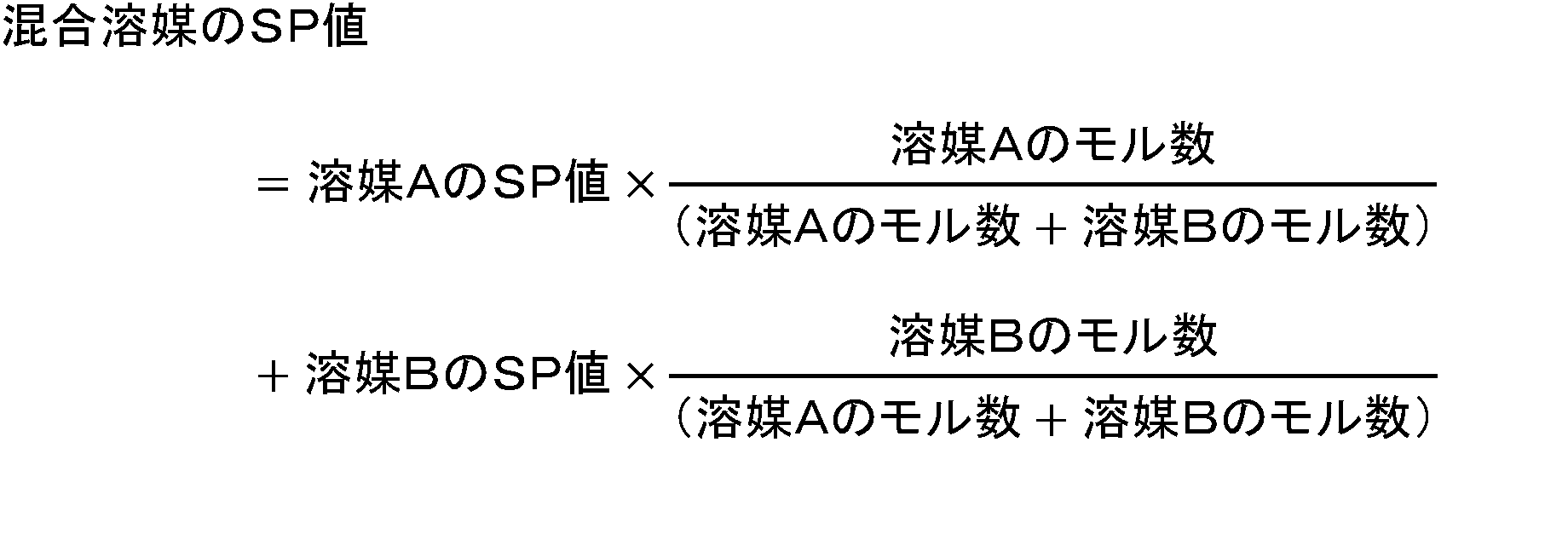
(e)成分は、各塗布液にて溶媒となるもので、実質的にSP値が8~11.5(cal/cm3)1/2である非水溶媒からなる。「実質的にSP値が8~11.5(cal/cm3)1/2である非水溶媒」とは、「SP値が8~11.5(cal/cm3)1/2である単独種の非水溶媒」、「SP値が8~11.5(cal/cm3)1/2である非水溶媒のみを組み合わせ、その混合溶媒のSP値が8~11.5(cal/cm3)1/2の範囲に入る溶媒」、及び、「SP値が8~11.5(cal/cm3)1/2である非水溶媒とそれ以外のSP値の溶媒を組み合わせ、その混合溶媒のSP値が8~11.5(cal/cm3)1/2の範囲に入る溶媒」を意味する。なお、混合溶媒のSP値は、例えば「溶媒A」と「溶媒B」の2種類を用いた場合、以下の計算式から算出することができる。
塗布液に含まれる溶媒のSP値が8~11.5(cal/cm3)1/2であれば、本開示で使用される紫外線吸収剤を該塗布液中に均一に分散することができ、ひいては、得られる被膜中においても前記紫外線吸収剤を均一に分散させることができる。なお、溶媒のSP値が8未満であると、塗布後に塗膜から前記紫外線吸収剤が析出し、最終的に得られる被膜が不透明になってしまう場合がある。
また、本開示の塗布液に含まれる溶媒が、SP値が8~10.5(cal/cm3)1/2である非水溶媒から実質的に構成されたものであると、得られる塗布液のレベリング性が向上するため、後述するレベリング工程を行う場合に、より短時間で塗膜のレベリングが完了するため好ましい。
SP値が8~11.5(cal/cm3)1/2である非水溶媒としては、例えば、芳香族炭化水素類のトルエン(SP値:9.1(cal/cm3)1/2)、キシレン(SP値:9.1(cal/cm3)1/2)、酢酸エステル類の酢酸エチル(SP値:8.8(cal/cm3)1/2)、酢酸ブチル(SP値:8.7(cal/cm3)1/2)、ケトン類のアセトン(SP値:9.1(cal/cm3)1/2)、メチルエチルケトン(SP値:9.0(cal/cm3)1/2)、メチルイソブチルケトン(SP値:8.3(cal/cm3)1/2)、シクロヘキサノン(SP値:9.8(cal/cm3)1/2)、2-ヘプタノン(SP値:8.5(cal/cm3)1/2)、グリコールエーテル類の3-メトキシ-3-メチルブタノール(SP値:10.5(cal/cm3)1/2)、1-メトキシ-2-プロパノール(SP値:11.3(cal/cm3)1/2)、1-エトキシ-2-プロパノール(SP値:10.9(cal/cm3)1/2)、3-メトキシブチルアセテート(SP値:8.8(cal/cm3)1/2)、ジエチレングリコールモノブチルエーテル(SP値:10.5(cal/cm3)1/2)、エーテル類のTHF(SP値:8.3(cal/cm3)1/2)、セロソルブ類のエチレングリコールモノエチルエーテル(SP値:11.5(cal/cm3)1/2)、エチレングリコールモノノルマルブチルエーテル(SP値:10.8(cal/cm3)1/2)、酢酸2-メトキシブチル(SP値:9.0(cal/cm3)1/2)、塩化炭化水素類のジクロロメタン(SP値:10.2(cal/cm3)1/2)、その他としてN、N-ジメチルホルムアミド(SP値:10.2(cal/cm3)1/2)等が挙げられ、中でもケトン類のメチルエチルケトン(SP値:9.0(cal/cm3)1/2)、メチルイソブチルケトン(SP値:8.3(cal/cm3)1/2)、シクロヘキサノン(SP値:9.8(cal/cm3)1/2)、2-ヘプタノン(SP値:8.5(cal/cm3)1/2)やグリコールエーテル類の3-メトキシ-3-メチルブタノール(SP値:10.5(cal/cm3)1/2)、1-メトキシ-2-プロパノール(SP値:11.3(cal/cm3)1/2)、1-エトキシ-2-プロパノール(SP値:10.9(cal/cm3)1/2)が好ましい。
また、前記(e)成分に加えて、各塗布液は、SP値が8~11.5(cal/cm3)1/2以外の溶媒を含んでいてもよく、例えば、n-ヘキサン(SP値:7.3(cal/cm3)1/2)、ジエチルエーテル(SP値:7.3(cal/cm3)1/2)、2-メトキシエタノール(SP値:12.0(cal/cm3)1/2)、四塩化炭素(SP値:12.2(cal/cm3)1/2)等が挙げられる。
前記(e)成分は、前記紫外線吸収剤を使用する場合に好適に使用されるものであるが、前記紫外線吸収剤を使用しない場合は、各塗布液は、前記(e)成分以外にも、他の溶媒、例えば水、アルコール類、ケトン類等を含んでもよい。
<(f)成分について>
(f)成分の顔料は、前記第一着色被膜の色味に応じて選択される。青色顔料として、例えばPigmentBlue15、PigmentBlue28、セシウム酸化タングステン(CWO)微粒子、緑色顔料として、例えばPigmentGreen36、PigmentGreen56、黄色顔料として、例えばPigmentYellow150、PigmentYellow119、赤色顔料として、例えばPigmentRed101、PigmentRed254、橙色顔料として、例えばPigmentOrange71、黒色顔料として、例えばPigmentBlack26、桃色顔料として、例えばPigmentRed202、PigmentViolet19等が挙げられる。前記顔料の平均粒子径D50は、10~300nmであることが好ましい。D50が10nm未満の場合、凝集しやすい傾向があり、300nm超の場合、可視光線透過率が悪化する傾向がある。これらを考慮すると、前記顔料の平均粒子径D50は、15~280nm、さらには20~250nmとすることが好ましい。尚、前記D50は、前記顔料の粒子を動的散乱法により水中での体積分布を測定して得られた粒度分布における、累積50%粒径のことである。
(f)成分の顔料は、前記第一着色被膜の色味に応じて選択される。青色顔料として、例えばPigmentBlue15、PigmentBlue28、セシウム酸化タングステン(CWO)微粒子、緑色顔料として、例えばPigmentGreen36、PigmentGreen56、黄色顔料として、例えばPigmentYellow150、PigmentYellow119、赤色顔料として、例えばPigmentRed101、PigmentRed254、橙色顔料として、例えばPigmentOrange71、黒色顔料として、例えばPigmentBlack26、桃色顔料として、例えばPigmentRed202、PigmentViolet19等が挙げられる。前記顔料の平均粒子径D50は、10~300nmであることが好ましい。D50が10nm未満の場合、凝集しやすい傾向があり、300nm超の場合、可視光線透過率が悪化する傾向がある。これらを考慮すると、前記顔料の平均粒子径D50は、15~280nm、さらには20~250nmとすることが好ましい。尚、前記D50は、前記顔料の粒子を動的散乱法により水中での体積分布を測定して得られた粒度分布における、累積50%粒径のことである。
前記顔料は、前記第一塗布液において、(d)成分の紫外線吸収剤に対して、質量比で0.02~0.50倍含ませることができる。0.02倍未満だと、第一着色被膜の発色性が悪くなる傾向があり、0.50倍超の場合、ヘーズが高くなる傾向がある。これらを考慮すると、前記顔料は、第一塗布液において、紫外線吸収剤に対して、質量比で0.025~0.45倍、さらには0.03~0.36倍含むものとすることが好ましい。第二塗布液(A)は、顔料を含むものであるが、その含有量は、第一着色被膜の可視光線透過率よりも低くなるように調整される。第二塗布液(A)が、(d)成分の紫外線吸収剤を含む場合、前記紫外線吸収剤に対して、質量比で0.02倍未満含ませてもよい。
<その他の成分>
前記各塗布液は、導電性物質からなる微粒子を含んでもよい。導電性物質からなる微粒子を含むことで、着色被膜付板ガラスに赤外線遮蔽性をもたらすことでできる。導電性物質として例えばITO(スズ酸化インジウム)、ATO(アンチモン酸化スズ)等が挙げられる。含有量は全固形分に対して5~15質量%含むものとしてよく、その平均粒子径D50は50~100nmのものを使用してもよい。また、前記各塗布液は、上記成分以外にも、その用途に応じて、防黴剤、光触媒材料、防錆剤、防食剤、防藻剤、撥水剤、撥油剤、光安定剤、酸化防止剤、基材湿潤剤、親水性材料、吸水性材料などを含ませてもよい。
前記各塗布液は、導電性物質からなる微粒子を含んでもよい。導電性物質からなる微粒子を含むことで、着色被膜付板ガラスに赤外線遮蔽性をもたらすことでできる。導電性物質として例えばITO(スズ酸化インジウム)、ATO(アンチモン酸化スズ)等が挙げられる。含有量は全固形分に対して5~15質量%含むものとしてよく、その平均粒子径D50は50~100nmのものを使用してもよい。また、前記各塗布液は、上記成分以外にも、その用途に応じて、防黴剤、光触媒材料、防錆剤、防食剤、防藻剤、撥水剤、撥油剤、光安定剤、酸化防止剤、基材湿潤剤、親水性材料、吸水性材料などを含ませてもよい。
<車両用窓ガラスの第一製造方法>
図1及び図2に示す車両用窓ガラス1は、前記各塗布液を湾曲したガラス板2の凹面側主面21又は凸面側主面22に塗布することで、製造することができる。
前記車両用窓ガラス1の第一製造方法は、
主面(凹面側主面21及び凸面側主面22)を備える湾曲したガラス板2と、前記主面(凹面側主面21又は凸面側主面22)上に、第一着色被膜からなる第一被膜部31と、前記第一着色被膜よりも可視光線透過率が高い第二着色被膜又は無色被膜からなる第二被膜部32とを備える車両用窓ガラス1の製造方法であって、
前記第一塗布液と、前記第二塗布液((A)又は(B))とを準備する工程(1)と、
前記第一塗布液をスプレー法で、前記第一被膜部31の形成予定箇所に前記第一塗布液のミスト51を散布して、前記第一塗布液の液膜61を調製する工程(2a)と、
前記第二塗布液をスプレー法で、前記第二被膜部32の形成予定箇所に前記第二塗布液のミスト52を散布して、前記第二塗布液の液膜62と前記第一塗布液の液膜61とが一体化して、液膜61と液膜62との混合液膜63を形成するように、前記第二塗布液の液膜62を調製する工程(2b)と、
各液膜を、乾燥、及び硬化させる工程(3)と、を備え、
前記工程(2b)時において、工程(2a)時に前記第一塗布液のミスト51によって前記第二被膜部32の形成予定箇所に形成された第一塗布液の液滴状物71が乾燥する前に、前記第二塗布液のミスト52を散布して、前記第二塗布液の液膜62を調製する。
図1及び図2に示す車両用窓ガラス1は、前記各塗布液を湾曲したガラス板2の凹面側主面21又は凸面側主面22に塗布することで、製造することができる。
前記車両用窓ガラス1の第一製造方法は、
主面(凹面側主面21及び凸面側主面22)を備える湾曲したガラス板2と、前記主面(凹面側主面21又は凸面側主面22)上に、第一着色被膜からなる第一被膜部31と、前記第一着色被膜よりも可視光線透過率が高い第二着色被膜又は無色被膜からなる第二被膜部32とを備える車両用窓ガラス1の製造方法であって、
前記第一塗布液と、前記第二塗布液((A)又は(B))とを準備する工程(1)と、
前記第一塗布液をスプレー法で、前記第一被膜部31の形成予定箇所に前記第一塗布液のミスト51を散布して、前記第一塗布液の液膜61を調製する工程(2a)と、
前記第二塗布液をスプレー法で、前記第二被膜部32の形成予定箇所に前記第二塗布液のミスト52を散布して、前記第二塗布液の液膜62と前記第一塗布液の液膜61とが一体化して、液膜61と液膜62との混合液膜63を形成するように、前記第二塗布液の液膜62を調製する工程(2b)と、
各液膜を、乾燥、及び硬化させる工程(3)と、を備え、
前記工程(2b)時において、工程(2a)時に前記第一塗布液のミスト51によって前記第二被膜部32の形成予定箇所に形成された第一塗布液の液滴状物71が乾燥する前に、前記第二塗布液のミスト52を散布して、前記第二塗布液の液膜62を調製する。
前記第一製造方法について、図4及び図5を参照しながら説明する。図4は、前記第一製造方法を模式的に説明する図であり、第一塗布液が第一スプレーノズル81から散布され、第一被膜部31となる第一塗布液の液膜61を調製したときの状態を模式的に表したものである。図5は、第一スプレーノズル81によって液膜61を形成後に、第二スプレーノズル82から第二塗布液を散布して第二塗布液の液膜62と、液膜61と液膜62との混合液膜63とを形成するときの状態を模式的に表したものである。スプレーノズル81、82は、移動しながら、例えば、図4、図5内の矢印の方向に移動しながら、スプレーノズルの先端から塗布液を散布し、ガラス板2に塗布液を塗布し、塗布液の液膜を形成していく。
前記液膜61の形成後、前記液膜61の流動性が保たれたまま、液膜62の形成を前記液膜61のエッジから隣接させて形成していくことで、該エッジで、両液膜61、62が混合されていく。その結果、該エッジが前記混合液膜63となる。前記第一塗布液の塗布条件と、前記第二塗布液の塗布条件を同じとすることで、前記液膜61、62、63が、一様な膜厚で一体化されたものとしやすくなる。そして、各塗布液から得られる膜厚が同程度となるように、塗布液の固形分濃度を調整することによって、前記第一被膜部31と前記第二被膜部32とで、一様な膜厚で一体化された被膜が得やすくなる。一様な膜厚で一体化された被膜の観点からすると、前記第一被膜部31の厚さと、前記第二被膜部32と厚さとの差は小さいことが好ましく、例えば、第一被膜部31の厚さと、第二被膜部32の厚さとの比は、0.80~1.20内、さらには0.95~1.05内とすることが好ましい。前記スプレーノズル81、82は、2個のスプレーノズルが使用されてもよい。また、一個のスプレーノズルにて、第一、第二塗布液が流れる配管のバルブ操作によって、一個のスプレーノズルから吐出される塗布液が、第一、第二塗布液の切り替えが行われて、第一塗布液が吐出されるときのスプレーノズルをスプレーノズル81、第二塗布液が吐出されるときのスプレーノズルをスプレーノズル82としてもよい。
<車両用窓ガラスの第二製造方法>
また、前記車両用窓ガラス1の第二製造方法は、
主面(凹面側主面21及び凸面側主面22)を備える湾曲したガラス板2と、前記主面(凹面側主面21又は凸面側主面22)上に、第一着色被膜からなる第一被膜部31と、前記第一着色被膜よりも可視光線透過率が高い第二着色被膜又は無色被膜からなる第二被膜部32とを備える車両用窓ガラスの製造方法であって、
第一被膜部形成用の第一塗布液と、第二被膜部形成用の第二塗布液((A)又は(B))とを準備する工程(1)と、
前記第二塗布液をスプレー法で、前記第二被膜部32の形成予定箇所に前記第二塗布液のミスト52を散布して、前記第二塗布液の液膜62を調製する工程(2c)と、
前記第一塗布液をスプレー法で、前記第一被膜部31の形成予定箇所に前記第一塗布液のミスト51を散布して、前記第一塗布液の液膜61と前記第二塗布液の液膜62とが一体化して、液膜61と液膜62との混合液膜63を形成するように、前記第一塗布液の液膜61を調製する工程(2d)と、
各液膜を、乾燥、及び硬化させる工程(3)と、を備え、
前記工程(2d)時において、工程(2c)時に前記第二塗布液のミスト52によって前記第一被膜部の形成予定箇所に形成された第二塗布液の液滴状物72が乾燥する前に、前記第一塗布液のミスト51を散布して、前記第一塗布液の液膜61を調製する。
また、前記車両用窓ガラス1の第二製造方法は、
主面(凹面側主面21及び凸面側主面22)を備える湾曲したガラス板2と、前記主面(凹面側主面21又は凸面側主面22)上に、第一着色被膜からなる第一被膜部31と、前記第一着色被膜よりも可視光線透過率が高い第二着色被膜又は無色被膜からなる第二被膜部32とを備える車両用窓ガラスの製造方法であって、
第一被膜部形成用の第一塗布液と、第二被膜部形成用の第二塗布液((A)又は(B))とを準備する工程(1)と、
前記第二塗布液をスプレー法で、前記第二被膜部32の形成予定箇所に前記第二塗布液のミスト52を散布して、前記第二塗布液の液膜62を調製する工程(2c)と、
前記第一塗布液をスプレー法で、前記第一被膜部31の形成予定箇所に前記第一塗布液のミスト51を散布して、前記第一塗布液の液膜61と前記第二塗布液の液膜62とが一体化して、液膜61と液膜62との混合液膜63を形成するように、前記第一塗布液の液膜61を調製する工程(2d)と、
各液膜を、乾燥、及び硬化させる工程(3)と、を備え、
前記工程(2d)時において、工程(2c)時に前記第二塗布液のミスト52によって前記第一被膜部の形成予定箇所に形成された第二塗布液の液滴状物72が乾燥する前に、前記第一塗布液のミスト51を散布して、前記第一塗布液の液膜61を調製する。
前記第二製造方法について、図6及び図7を参照しながら説明する。図6は、前記第二製造方法を模式的に説明する図であり、第二塗布液が第二スプレーノズル82から散布され、第二被膜部32となる第二塗布液の液膜62を調製したときの状態を模式的に表したものである。図7は、第二スプレーノズル82によって液膜62を形成後に、第一スプレーノズル81から第一塗布液を散布して第一塗布液の液膜61と、液膜61と液膜62との混合液膜63とを形成するときの状態を模式的に表したものである。スプレーノズル81、82は、移動しながら、例えば、図6、図7内の矢印の方向に移動しながら、スプレーノズルの先端から塗布液を散布し、ガラス板2に塗布液を塗布し、塗布液の液膜を形成していく。
前記スプレーノズル81、82は、2個のスプレーノズルが使用されてもよい。また、一個のスプレーノズルにて、第一、第二塗布液が流れる配管のバルブ操作によって、一個のスプレーノズルから吐出される塗布液が、第一、第二塗布液の切り替えが行われて、第一塗布液が吐出されるときのスプレーノズルをスプレーノズル81、第二塗布液が吐出されるときのスプレーノズルをスプレーノズル82としてもよい。
前記第一製造方法と、前記第二製造方法は、ガラス板2への第一塗布液と、第二塗布液の塗布する順序が異なるだけで、それ以外は同じ製法となる。
<塗布液のスプレー塗布工程>
塗布液をスプレーノズルから散布してガラス板2に塗布する方法では、図4~図7に示したように、被塗布物の塗布領域を狙う、塗布液のミスト51、52だけでなく、ミスト51、52から拡散して広がってしまうミスト51a、52aが生じてしまう。そのため、各塗布液の塗布対象領域外に飛散し、ガラス板2の主面に液滴状物71、72が形成される。本開示では、液滴状物71、72が乾燥する前に液滴状物71、72を包含して液膜63を形成するので、液膜63内で、液滴状物71、72が拡散し、液滴状物71、72が消失することになり、液滴状物71、72に起因する被膜の外観不良を抑制することができる。液滴状物71、72の総量は、被膜の総量に対して、微量なので、形成される被膜に与える影響はほとんど無く、目視においては、被膜の色味に影響は生じない。
塗布液をスプレーノズルから散布してガラス板2に塗布する方法では、図4~図7に示したように、被塗布物の塗布領域を狙う、塗布液のミスト51、52だけでなく、ミスト51、52から拡散して広がってしまうミスト51a、52aが生じてしまう。そのため、各塗布液の塗布対象領域外に飛散し、ガラス板2の主面に液滴状物71、72が形成される。本開示では、液滴状物71、72が乾燥する前に液滴状物71、72を包含して液膜63を形成するので、液膜63内で、液滴状物71、72が拡散し、液滴状物71、72が消失することになり、液滴状物71、72に起因する被膜の外観不良を抑制することができる。液滴状物71、72の総量は、被膜の総量に対して、微量なので、形成される被膜に与える影響はほとんど無く、目視においては、被膜の色味に影響は生じない。
スプレーノズルから散布されるミストは、塗布液の液滴の集合体である。前記液滴の大きさは、液滴を球形とみなしたときに、1μmφ~500μmφの大きさのものとしてよい。前記液滴の大きさは、スプレーノズルの圧力条件や塗布液の粘度などによって調整することができる。前記ミストに基づいて形成される液滴状物71、72は、液膜61、62のエッジ(縁部)からの距離によって状態が変化する。液滴状物71、72の形状は様々であり、液膜61、62のエッジから離れると半球状の物が多く、該エッジに近づくに伴い球同士がランダムに連なり不定形な形状を呈するようなる。
前記第一製造方法では、液滴状物71が乾燥する前に液滴状物71を包含して液膜62を形成するので、液膜62の形成時には、液滴状物71ですら乾燥していないので、液膜61は、液状を維持した状態である。よって、液膜61と液膜62との境界領域で、液膜61と液膜62との混合液膜63が形成される。一方、前記第二製造方法では、液滴状物72が乾燥する前に液滴状物72を包含して液膜61を形成するので、液膜61の形成時には、液滴状物72ですら乾燥していないので、液膜62は、液状を維持した状態である。よって、液膜61と液膜62との境界領域で、液膜61と液膜62との混合液膜63が形成される。
液膜61、62の厚みを同じとするために、各塗布液の塗布量を調整する共に、液膜61、液膜62、混合液膜63が形成された状態で、各液膜が一様な液面状態を形成するように、ガラス板2を静置、すなわち、レベリング工程を設けることが好ましい。レベリング工程は、室温で5~20分間実施することが好ましい。また、レベリング工程では、ガラス板2に超音波振動を付与して、各液膜が一様な液面状態の形成を促進しても良い。
<塗布液膜の乾燥、硬化工程>
ガラス板2に各液膜を形成後、各液膜中の溶媒を蒸発させる乾燥工程を行う。この乾燥工程は、液膜が形成されたガラス板2を20℃~300℃で加熱することで行ってもよいし、室温で静置して乾燥させてもよい。次いで、100~350℃の熱と水蒸気に曝すことにより、塗膜(溶媒が蒸発した液膜を、塗膜とする)の硬化を進行させて、ガラス板2の主面に第一被膜部31、第二被膜部32、境界部33を形成する。ガラス板2の温度や、塗膜に接触させる水蒸気の量を安定させるため、硬化工程をチャンバー内で行うことが好ましい。前記塗膜が形成されたガラス板2を100℃超~350℃の過熱水蒸気に曝すと、短時間で脱水縮合反応が進行し、高硬度の被膜が得られるためより好ましい。さらに好ましい過熱水蒸気の温度は100℃超~300℃である。なお、過熱水蒸気とは、100℃の飽和水蒸気を更に加熱して得られる100℃超の水蒸気である。
ガラス板2に各液膜を形成後、各液膜中の溶媒を蒸発させる乾燥工程を行う。この乾燥工程は、液膜が形成されたガラス板2を20℃~300℃で加熱することで行ってもよいし、室温で静置して乾燥させてもよい。次いで、100~350℃の熱と水蒸気に曝すことにより、塗膜(溶媒が蒸発した液膜を、塗膜とする)の硬化を進行させて、ガラス板2の主面に第一被膜部31、第二被膜部32、境界部33を形成する。ガラス板2の温度や、塗膜に接触させる水蒸気の量を安定させるため、硬化工程をチャンバー内で行うことが好ましい。前記塗膜が形成されたガラス板2を100℃超~350℃の過熱水蒸気に曝すと、短時間で脱水縮合反応が進行し、高硬度の被膜が得られるためより好ましい。さらに好ましい過熱水蒸気の温度は100℃超~300℃である。なお、過熱水蒸気とは、100℃の飽和水蒸気を更に加熱して得られる100℃超の水蒸気である。
以下により具体的な例として、本開示の車両用窓ガラスを、実施例、比較例にて説明する。
実施例1
第一塗布液と第二塗布液とを準備する工程
<第一塗布液(第一被膜部31用塗布液)の調製>
反応容器中において、(a-1)成分として、3-アミノプロピルトリエトキシシラン液9.72gに、(a-2)成分として、ホウ酸(H3BO3)粉末1.61gを加え((a-1)成分1モルに対して(a-2)成分を0.6モルの比率で添加)、23℃5分間攪拌後、(b)成分として、テトラメトキシシラン17.38gを添加し((a-1)成分1モルに対して(b)成分が2.6モルの比率で存在するように添加)、(c)成分として、ナガセケムテックス製エポキシ樹脂CY232を5.08g(全固形分に対して18質量%の比率で存在するように添加)添加した後、60℃で120時間反応させ粘稠な液体を形成した。
第一塗布液と第二塗布液とを準備する工程
<第一塗布液(第一被膜部31用塗布液)の調製>
反応容器中において、(a-1)成分として、3-アミノプロピルトリエトキシシラン液9.72gに、(a-2)成分として、ホウ酸(H3BO3)粉末1.61gを加え((a-1)成分1モルに対して(a-2)成分を0.6モルの比率で添加)、23℃5分間攪拌後、(b)成分として、テトラメトキシシラン17.38gを添加し((a-1)成分1モルに対して(b)成分が2.6モルの比率で存在するように添加)、(c)成分として、ナガセケムテックス製エポキシ樹脂CY232を5.08g(全固形分に対して18質量%の比率で存在するように添加)添加した後、60℃で120時間反応させ粘稠な液体を形成した。
この液体に、(e)成分の溶媒として2-ヘプタノン(SP値:8.5(cal/cm3)1/2)37.22g、グリコールエーテル類の3-メトキシ-3-メチルブタノール(SP値:10.5(cal/cm3)1/2)22.78gを添加し、(d)成分の紫外線吸収剤としてBASF製のトリアジン系紫外線吸収剤TINUVIN460(SP値:10.9(cal/cm3)1/2)を1.01g、TINUVIN477(SP値:11.4(cal/cm3)1/2)を1.35g、光安定剤としてTINUVIN292を0.47g、表面調整剤として信越シリコーン製KP-301を0.68g、導電性物質としてITO微粒子分散液(固形分濃度:20%)をITO微粒子換算で2.20g、(f)成分として顔料分散体(固形分濃度:10%、黒色顔料としてカーボンブラックを用いた)をカーボンブラック換算で0.51g添加して、固形分濃度が21質量%である塗布液とした。なお、該塗布液中に含まれる溶媒のSP値は9.0(cal/cm3)1/2である。
作製された塗布液は着色透明であった。また、凝集等による白濁は確認されず、紫外線吸収剤およびカーボンブラックが塗布液中で均一に分散されているものであった。
<第二塗布液(第二被膜部32用塗布液)の調製>
前記第一塗布液に使用された、紫外線吸収剤、光安定剤、導電性物質、および顔料分散体を省き、それ以外は、同じ成分とした。そして、固形分濃度は、第一塗布液と同じ21質量%となるように各成分の量を調整し、これを第二塗布液とした。
前記第一塗布液に使用された、紫外線吸収剤、光安定剤、導電性物質、および顔料分散体を省き、それ以外は、同じ成分とした。そして、固形分濃度は、第一塗布液と同じ21質量%となるように各成分の量を調整し、これを第二塗布液とした。
<ガラス板の準備>
車両用窓ガラス用に湾曲加工された、厚さ3.1mmのセントラル硝子製のグリーンガラス(通称:MFL)からなるガラス板2を準備した。同ガラス板2の大きさは、1200mm(横方向)×500mm(縦方向)で、3次元曲げを有するものであった。
また、同ガラス板の凹面側主面21の周縁部には、黒色のセラミックペーストから形成された、幅40mm(部分的に、上辺の中央域において、幅110mmとなっている箇所がある)、厚さ12.5μmの帯状の可視光遮蔽層(黒セラミック)4が配置されたもので、さらには、前記凹面側主面21に、銀ペーストから形成された、幅0.45mm、厚さ10μmの直線状の導電パターンが31mm間隔で配置されたものである。また、前記凹面側主面21は、第一塗布液と第二塗布液とが塗布される直前に、セリア粉末による研磨の後、水洗と、乾燥とがなされたものである。
車両用窓ガラス用に湾曲加工された、厚さ3.1mmのセントラル硝子製のグリーンガラス(通称:MFL)からなるガラス板2を準備した。同ガラス板2の大きさは、1200mm(横方向)×500mm(縦方向)で、3次元曲げを有するものであった。
また、同ガラス板の凹面側主面21の周縁部には、黒色のセラミックペーストから形成された、幅40mm(部分的に、上辺の中央域において、幅110mmとなっている箇所がある)、厚さ12.5μmの帯状の可視光遮蔽層(黒セラミック)4が配置されたもので、さらには、前記凹面側主面21に、銀ペーストから形成された、幅0.45mm、厚さ10μmの直線状の導電パターンが31mm間隔で配置されたものである。また、前記凹面側主面21は、第一塗布液と第二塗布液とが塗布される直前に、セリア粉末による研磨の後、水洗と、乾燥とがなされたものである。
第二被膜部32の形成部はハイマウントストップランプの設置を想定し、ガラス板2の上辺にある可視光遮蔽層4のエッジを始点とし、ガラス板2の透明部分の中央側に縦50mm、横250mmの長方形となるように設定した。
<スプレー装置>
前記第一、第二塗布液を塗布するための第一スプレーノズル81、第二スプレーノズル82として、ロボット先端に取り付けられたベルカップ回転霧化式エアースプレーガン(旭サナック製、ASG200)を用いた。そして、塗布時の条件として、ベルカップ回転数を20,000rpm、ワイドシェープエアーを0.05MPa、ショートシェープエアーを0.10MPaに設定した。
前記第一、第二塗布液を塗布するための第一スプレーノズル81、第二スプレーノズル82として、ロボット先端に取り付けられたベルカップ回転霧化式エアースプレーガン(旭サナック製、ASG200)を用いた。そして、塗布時の条件として、ベルカップ回転数を20,000rpm、ワイドシェープエアーを0.05MPa、ショートシェープエアーを0.10MPaに設定した。
第一塗布液の液膜を調製する工程
<第一塗布液のミスト散布>
前記ガラス板2を、凹面側主面21を上側に、凸面側主面22を地面側とし、前記ガラス板2を概略水平に静置した。前記スプレーノズル81の先端と、前記凹面側主面21との距離を85mmに保ちつつ、前記スプレーノズル81を前記凹面側主面21上でコンピュータ制御でスキャンしながら、前記スプレーノズル81の先端から第一塗布液のミスト51を散布し、前記凹面側主面21に、第一塗布液の液膜61を形成した。前記第一塗布液の液膜61は、第二被膜部32形成領域を除く、その他の領域に形成された。
<第一塗布液のミスト散布>
前記ガラス板2を、凹面側主面21を上側に、凸面側主面22を地面側とし、前記ガラス板2を概略水平に静置した。前記スプレーノズル81の先端と、前記凹面側主面21との距離を85mmに保ちつつ、前記スプレーノズル81を前記凹面側主面21上でコンピュータ制御でスキャンしながら、前記スプレーノズル81の先端から第一塗布液のミスト51を散布し、前記凹面側主面21に、第一塗布液の液膜61を形成した。前記第一塗布液の液膜61は、第二被膜部32形成領域を除く、その他の領域に形成された。
このとき、この第一塗布液の液膜61の形成領域外の第二塗布液塗布部には、前記第一塗布液の液滴状物71が形成された。液滴状物71の形状は様々であり、液膜61のエッジから40mm以上離れると半球状の物が多く、半径が10μm~50μmであった。液膜61のエッジから20~40mmの範囲においては前記半球状液滴に加えて半球同士がランダムに連なり不定形をなしていた。不定形状液物の最大長さは200~500μm程度であった。液膜61のエッジから0~20mmの範囲においては前記不定形状のもの及び1.0μmの膜厚を有する薄膜状となっていた。第二塗布液塗布部の全面において前記いずれかのものが観測された。
第二塗布液の液膜を調製する工程
<第二塗布液のミスト散布>
次いで、前記スプレーノズル82の先端と、前記凹面側主面21との距離を85mmに保ちつつ、前記スプレーノズル82を前記凹面側主面21上でスキャンしながら、前記スプレーノズル82の先端から第二塗布液のミスト52を散布し、前記第一塗布液の液膜61が形成されていない前記凹面側主面21の残部に、第二塗布液の液膜62を形成した。前記第二塗布液の液膜62の形成にあたって、前記液滴状物71が乾燥する前に前記第二塗布液のミスト52の散布がなされ、前記第一塗布液の液膜61と、前記第二塗布液の液膜62との境界領域では両液膜61、62が一体化するように、具体的には混合液膜63の膜厚が液膜61および62と同等になるようにスキャン幅、第二塗布液の吐出量、塗装速度をコンピュータ制御により調整し、混合液膜63が調製された。第一塗布液の液膜61の前記凹面側主面21への吐出条件、第二塗布液の液膜62の前記凹面側主面21への吐出条件とは同一とした。
<第二塗布液のミスト散布>
次いで、前記スプレーノズル82の先端と、前記凹面側主面21との距離を85mmに保ちつつ、前記スプレーノズル82を前記凹面側主面21上でスキャンしながら、前記スプレーノズル82の先端から第二塗布液のミスト52を散布し、前記第一塗布液の液膜61が形成されていない前記凹面側主面21の残部に、第二塗布液の液膜62を形成した。前記第二塗布液の液膜62の形成にあたって、前記液滴状物71が乾燥する前に前記第二塗布液のミスト52の散布がなされ、前記第一塗布液の液膜61と、前記第二塗布液の液膜62との境界領域では両液膜61、62が一体化するように、具体的には混合液膜63の膜厚が液膜61および62と同等になるようにスキャン幅、第二塗布液の吐出量、塗装速度をコンピュータ制御により調整し、混合液膜63が調製された。第一塗布液の液膜61の前記凹面側主面21への吐出条件、第二塗布液の液膜62の前記凹面側主面21への吐出条件とは同一とした。
前記第一塗布液の液膜61と、前記第二塗布液の液膜62とが形成されたガラス板2は、15分間水平に静置された。
各液膜を、乾燥、及び硬化させる工程
次いで、前記第一塗布液の液膜61と、前記第二塗布液の液膜62とが形成されたガラス板2は、180℃の熱風循環炉内にて5分間加熱され、各液膜の乾燥がなされた。この加熱の後、同物品は、180℃の過熱水蒸気に10分間曝露された。上記工程を経て、車両用窓ガラス1が得られた。本実施例の車両用窓ガラス1では、第一被膜部31と、第二被膜部32との間に、境界部33が形成された。
次いで、前記第一塗布液の液膜61と、前記第二塗布液の液膜62とが形成されたガラス板2は、180℃の熱風循環炉内にて5分間加熱され、各液膜の乾燥がなされた。この加熱の後、同物品は、180℃の過熱水蒸気に10分間曝露された。上記工程を経て、車両用窓ガラス1が得られた。本実施例の車両用窓ガラス1では、第一被膜部31と、第二被膜部32との間に、境界部33が形成された。
車両用窓ガラスの評価
本実施例の車両用窓ガラス1は、以下の評価方法で評価された。各種評価結果は、表1に示された。前記境界部33では、第一被膜部31側から、第二被膜部32側に向けて、可視光線透過率が徐々に増加し、境界部33が目立たないものとなった。
本実施例の車両用窓ガラス1は、以下の評価方法で評価された。各種評価結果は、表1に示された。前記境界部33では、第一被膜部31側から、第二被膜部32側に向けて、可視光線透過率が徐々に増加し、境界部33が目立たないものとなった。
[外観]
照度が1000ルクスの環境下で、光源から800mmの距離とする目視観察にて、車両用窓ガラス1の被膜に、クラック、着色、白濁(被膜中で紫外線吸収剤が凝集等により均一に分散されていない)、光学歪、スプレーミスト痕等、外観上の不具合がないかどうか確認した。また、同時に、境界部33の幅をノギスで測定した。
照度が1000ルクスの環境下で、光源から800mmの距離とする目視観察にて、車両用窓ガラス1の被膜に、クラック、着色、白濁(被膜中で紫外線吸収剤が凝集等により均一に分散されていない)、光学歪、スプレーミスト痕等、外観上の不具合がないかどうか確認した。また、同時に、境界部33の幅をノギスで測定した。
[膜厚]
小坂研究所製サーフコーダーET4000Aを用いて、車両用窓ガラス1の被膜の膜厚を測定した。
小坂研究所製サーフコーダーET4000Aを用いて、車両用窓ガラス1の被膜の膜厚を測定した。
[可視光線透過率]
日立製分光光度計U-4100を用いて、車両用窓ガラス1の可視光線透過率を、JIS R3212(2015年)に準拠し算出した。測定においては、第一被膜部31、第二被膜部32は、共にそれぞれの被膜領域の中央付近で測定された。また、境界部33の透過率は、本実施例に合うように、ガラス板2の上辺側の可視光遮蔽層4(40mm幅の箇所)の、ガラス板2の中央側の縁から鉛直方向に、35mm、50mm、65mmの点で測定された。それぞれでの、測定結果は、表1で、境界部33(1)、境界部33(2)、境界部33(3)と表記される。
日立製分光光度計U-4100を用いて、車両用窓ガラス1の可視光線透過率を、JIS R3212(2015年)に準拠し算出した。測定においては、第一被膜部31、第二被膜部32は、共にそれぞれの被膜領域の中央付近で測定された。また、境界部33の透過率は、本実施例に合うように、ガラス板2の上辺側の可視光遮蔽層4(40mm幅の箇所)の、ガラス板2の中央側の縁から鉛直方向に、35mm、50mm、65mmの点で測定された。それぞれでの、測定結果は、表1で、境界部33(1)、境界部33(2)、境界部33(3)と表記される。
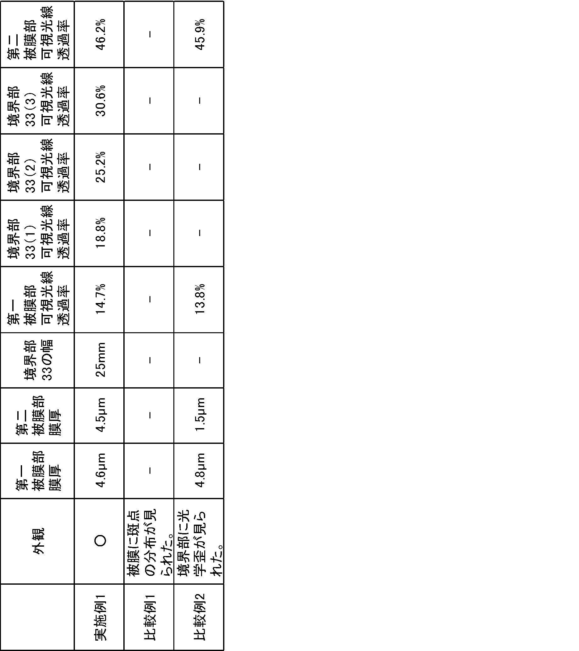
比較例1
前記第二塗布液の液膜62の形成にあたって、前記液滴状物71が乾燥した後に前記第二塗布液のミスト52の散布がなされた以外は、実施例1と同様の操作を経て、車両用窓ガラス1が得られた。本比較例の車両用窓ガラス1では、第二被膜部32に、液滴状物71が原因と思われる、斑点の分布が見られ、可視光線透過領域として不適当なものであった。
前記第二塗布液の液膜62の形成にあたって、前記液滴状物71が乾燥した後に前記第二塗布液のミスト52の散布がなされた以外は、実施例1と同様の操作を経て、車両用窓ガラス1が得られた。本比較例の車両用窓ガラス1では、第二被膜部32に、液滴状物71が原因と思われる、斑点の分布が見られ、可視光線透過領域として不適当なものであった。
比較例2
第一被膜部31と比べて第二被膜部32の膜厚が薄くなるように、第二塗布液の塗布量を減らした以外は、実施例1と同様の操作を経て、車両用窓ガラス1が得られた。本比較例の車両用窓ガラス1では、境界部33にて、光学歪が見られた。
第一被膜部31と比べて第二被膜部32の膜厚が薄くなるように、第二塗布液の塗布量を減らした以外は、実施例1と同様の操作を経て、車両用窓ガラス1が得られた。本比較例の車両用窓ガラス1では、境界部33にて、光学歪が見られた。
1 車両用窓ガラス
2 主面を備える湾曲したガラス板
21 凹面側主面
22 凸面側主面
31 第一被膜部
32 第二被膜部
33 境界部
4 可視光遮蔽層
51 第一塗布液のミスト
52 第二塗布液のミスト
61 第一塗布液の液膜
62 第二塗布液の液膜
63 液膜61と液膜62との混合液膜
71 塗布対象領域外に塗布された第一塗布液の液滴状物
72 塗布対象領域外に塗布された第二塗布液の液滴状物
81 第一スプレーノズル
82 第二スプレーノズル
2 主面を備える湾曲したガラス板
21 凹面側主面
22 凸面側主面
31 第一被膜部
32 第二被膜部
33 境界部
4 可視光遮蔽層
51 第一塗布液のミスト
52 第二塗布液のミスト
61 第一塗布液の液膜
62 第二塗布液の液膜
63 液膜61と液膜62との混合液膜
71 塗布対象領域外に塗布された第一塗布液の液滴状物
72 塗布対象領域外に塗布された第二塗布液の液滴状物
81 第一スプレーノズル
82 第二スプレーノズル
Claims (8)
- 主面を備える湾曲したガラス板と、
前記主面上に、第一着色被膜からなる第一被膜部と、前記第一被膜部に隣接し、前記第一着色被膜よりも可視光線透過率が高い第二着色被膜又は無色被膜からなる第二被膜部とを備える車両用窓ガラスであって、
前記第一被膜部と前記第二被膜部の被膜は、前記第一被膜部を形成するための第一塗布液と前記第二被膜部を形成するための第二塗布液の塗布乾燥によって形成された、一様な膜厚で一体化された被膜であり、
前記第一被膜部と前記第二被膜部との間には、前記第一塗布液と前記第二塗布液の混合によって形成された前記第一被膜部から前記第二被膜部にかけて可視光線透過率が徐変する境界部を有する、車両用窓ガラス。 - 前記第二被膜部は、前記境界部で囲撓され、前記境界部は、前記第一被膜部で囲撓されている、請求項1に記載の車両用窓ガラス。
- 前記主面直上に可視光遮蔽層を備え、前記可視光遮蔽層は、前記第一被膜部と、前記主面との間にある、請求項1又は2に記載の車両用窓ガラス。
- 前記第一着色被膜、及び前記第二着色被膜は、双方とも同じ顔料を有する、請求項1乃至3のいずれかに記載の車両用窓ガラス。
- 前記第二着色被膜の可視光線透過率は、前記第一着色被膜より20%以上高い、請求項1乃至4のいずれかに記載の車両用窓ガラス。
- 主面を備える湾曲したガラス板と、前記主面上に、第一着色被膜からなる第一被膜部と、前記第一被膜部に隣接し、前記第一着色被膜よりも可視光線透過率が高い第二着色被膜又は無色被膜からなる第二被膜部とを備える車両用窓ガラスの製造方法であって、
第一被膜部形成用の第一塗布液と、第二被膜部形成用の第二塗布液とを準備する工程(1)と、
前記第一塗布液をスプレー法で、前記第一被膜部の形成予定箇所に前記第一塗布液のミストを散布して、前記第一塗布液の液膜を調製する工程(2a)と、
前記第二塗布液をスプレー法で、前記第二被膜部の形成予定箇所に前記第二塗布液のミストを散布して、前記第二塗布液の液膜を調製する工程(2b)と、
各液膜を、乾燥、及び硬化させる工程(3)と、を備え、
前記工程(2b)時において、工程(2a)時に前記第一塗布液のミストによって前記第二被膜部の形成予定箇所に形成された第一塗布液の液滴状物が乾燥する前に、前記第二塗布液のミストを散布して、前記第一塗布液の液膜と前記第二塗布液の液膜との混合液膜からなる境界部を形成し、かつ前記第二塗布液の液膜を調製する、車両用窓ガラスの製造方法。 - 主面を備える湾曲したガラス板と、前記主面上に、第一着色被膜からなる第一被膜部と、前記第一被膜部に隣接し、前記第一着色被膜よりも可視光線透過率が高い第二着色被膜又は無色被膜からなる第二被膜部とを備える車両用窓ガラスの製造方法であって、
第一被膜部形成用の第一塗布液と、第二被膜部形成用の第二塗布液とを準備する工程(1)と、
前記第二塗布液をスプレー法で、前記第二被膜部の形成予定箇所に前記第二塗布液のミストを散布して、前記第二塗布液の液膜を調製する工程(2c)と、
前記第一塗布液をスプレー法で、前記第一被膜部の形成予定箇所に前記第一塗布液のミストを散布して、前記第一塗布液の液膜を調製する工程(2d)と、
各液膜を、乾燥、及び硬化させる工程(3)と、を備え、
前記工程(2d)時において、工程(2c)時に前記第二塗布液のミストによって前記第一被膜部の形成予定箇所に形成された第二塗布液の液滴状物が乾燥する前に、前記第一塗布液のミストを散布して、前記第二塗布液の液膜と前記第一塗布液の液膜との混合液膜からなる境界部を形成し、かつ前記第一塗布液の液膜を調製する、車両用窓ガラスの製造方法。 - 前記第一塗布液、及び前記第二塗布液の双方が、金属アルコキシド及び/又は金属アルコキシドの縮合物を含む、請求項6又は7に記載の車両用窓ガラスの製造方法。
Priority Applications (2)
| Application Number | Priority Date | Filing Date | Title |
|---|---|---|---|
| JP2020550331A JP7490560B2 (ja) | 2018-10-01 | 2019-09-25 | 車両用窓ガラス、及びその製造方法 |
| JP2023204627A JP7637216B2 (ja) | 2018-10-01 | 2023-12-04 | 車両用窓ガラス |
Applications Claiming Priority (2)
| Application Number | Priority Date | Filing Date | Title |
|---|---|---|---|
| JP2018186799 | 2018-10-01 | ||
| JP2018-186799 | 2018-10-01 |
Publications (1)
| Publication Number | Publication Date |
|---|---|
| WO2020071202A1 true WO2020071202A1 (ja) | 2020-04-09 |
Family
ID=70055082
Family Applications (1)
| Application Number | Title | Priority Date | Filing Date |
|---|---|---|---|
| PCT/JP2019/037559 Ceased WO2020071202A1 (ja) | 2018-10-01 | 2019-09-25 | 車両用窓ガラス、及びその製造方法 |
Country Status (2)
| Country | Link |
|---|---|
| JP (2) | JP7490560B2 (ja) |
| WO (1) | WO2020071202A1 (ja) |
Citations (5)
| Publication number | Priority date | Publication date | Assignee | Title |
|---|---|---|---|---|
| JPH0640252A (ja) * | 1992-05-27 | 1994-02-15 | Asahi Glass Co Ltd | 自動車用窓ガラス |
| JPH1045434A (ja) * | 1996-07-31 | 1998-02-17 | Central Glass Co Ltd | 自動車用電波透過型断熱ガラス |
| JPH10212137A (ja) * | 1996-03-07 | 1998-08-11 | Nippon Sheet Glass Co Ltd | 自動車用窓ガラスおよびこのガラスを用いた自動車窓構造 |
| JPH11302037A (ja) * | 1998-04-23 | 1999-11-02 | Central Glass Co Ltd | 低反射率、低透過率ガラス |
| JP2015224172A (ja) * | 2014-05-29 | 2015-12-14 | アイシン精機株式会社 | ロータス効果を有する被膜の製造方法及びロータス効果を有する被膜 |
Family Cites Families (4)
| Publication number | Priority date | Publication date | Assignee | Title |
|---|---|---|---|---|
| JPS57176432U (ja) * | 1981-05-06 | 1982-11-08 | ||
| JPH11335141A (ja) * | 1998-05-22 | 1999-12-07 | Nippon Sheet Glass Co Ltd | グラデーションを有する着色膜付きガラス板 |
| JP2000117874A (ja) | 1998-10-16 | 2000-04-25 | Central Glass Co Ltd | 退色基板およびその製造方法 |
| JP2003275673A (ja) | 2002-03-22 | 2003-09-30 | Matsushita Electric Works Ltd | 建築板塗装方法 |
-
2019
- 2019-09-25 WO PCT/JP2019/037559 patent/WO2020071202A1/ja not_active Ceased
- 2019-09-25 JP JP2020550331A patent/JP7490560B2/ja active Active
-
2023
- 2023-12-04 JP JP2023204627A patent/JP7637216B2/ja active Active
Patent Citations (5)
| Publication number | Priority date | Publication date | Assignee | Title |
|---|---|---|---|---|
| JPH0640252A (ja) * | 1992-05-27 | 1994-02-15 | Asahi Glass Co Ltd | 自動車用窓ガラス |
| JPH10212137A (ja) * | 1996-03-07 | 1998-08-11 | Nippon Sheet Glass Co Ltd | 自動車用窓ガラスおよびこのガラスを用いた自動車窓構造 |
| JPH1045434A (ja) * | 1996-07-31 | 1998-02-17 | Central Glass Co Ltd | 自動車用電波透過型断熱ガラス |
| JPH11302037A (ja) * | 1998-04-23 | 1999-11-02 | Central Glass Co Ltd | 低反射率、低透過率ガラス |
| JP2015224172A (ja) * | 2014-05-29 | 2015-12-14 | アイシン精機株式会社 | ロータス効果を有する被膜の製造方法及びロータス効果を有する被膜 |
Also Published As
| Publication number | Publication date |
|---|---|
| JP7490560B2 (ja) | 2024-05-27 |
| JP7637216B2 (ja) | 2025-02-27 |
| JPWO2020071202A1 (ja) | 2021-09-02 |
| JP2024026264A (ja) | 2024-02-28 |
Similar Documents
| Publication | Publication Date | Title |
|---|---|---|
| JP6458804B2 (ja) | 透光性構造体 | |
| JP7201370B2 (ja) | 膜付き曲げ基材およびその製造方法、ならびに画像表示装置 | |
| JP6747445B2 (ja) | 透光性構造体、その製造方法および物品 | |
| KR100783714B1 (ko) | 코팅재 조성물 및 그것에 의해 형성된 피막을 가지는 물품 | |
| JP5979151B2 (ja) | 低反射膜付き物品の製造方法 | |
| JPWO2015186669A1 (ja) | 防眩膜付き基材、その製造方法、および物品 | |
| WO2013051620A1 (ja) | 低反射膜付き物品の製造方法 | |
| JP7353971B2 (ja) | 透明物品の製造方法 | |
| JP2008163205A (ja) | 透明被膜形成用塗料および透明被膜付基材 | |
| JP2009160755A (ja) | 透明被膜付基材 | |
| JP2020122809A (ja) | 可視光散乱性被膜形成用塗布液、及び可視光散乱性被膜形成基材 | |
| WO2021095770A1 (ja) | 防眩層付基材及び画像表示装置並びに防眩層付基材の製造方法 | |
| JP6970349B2 (ja) | 着色被膜付ガラス物品 | |
| JP7637216B2 (ja) | 車両用窓ガラス | |
| JP2013160799A (ja) | 低反射膜付き物品の製造方法 | |
| JP2009119780A (ja) | 透明被膜付基材および透明被膜形成用塗布液 | |
| KR20150131499A (ko) | 저굴절률막 형성용 조성물 및 그 제조 방법 그리고 저굴절률막의 형성 방법 | |
| WO2018003772A1 (ja) | 多結晶ナノダイヤモンドを分散させた光散乱性被膜及び光散乱性被膜形成用塗布液 | |
| WO2021045037A1 (ja) | 車両後方情報取得システム | |
| JP5281241B2 (ja) | 透明性着色膜付基材および透明性着色膜形成用塗布液 | |
| JP4355178B2 (ja) | 蛍光ガラス容器およびその製造方法 | |
| JP6993590B2 (ja) | 着色被膜付板ガラスの製造方法 | |
| WO2022196218A1 (ja) | スプレーコート用コーティング液及びその製造方法、並びにアンチグレア層付き基材の製造方法 | |
| JP2022145461A (ja) | スプレーコート用コーティング液及びその製造方法、並びにアンチグレア層付き基材の製造方法 | |
| WO2019021643A1 (ja) | 可視光散乱性被膜形成用塗布液、及び可視光散乱性被膜形成基材 |
Legal Events
| Date | Code | Title | Description |
|---|---|---|---|
| 121 | Ep: the epo has been informed by wipo that ep was designated in this application |
Ref document number: 19869663 Country of ref document: EP Kind code of ref document: A1 |
|
| ENP | Entry into the national phase |
Ref document number: 2020550331 Country of ref document: JP Kind code of ref document: A |
|
| NENP | Non-entry into the national phase |
Ref country code: DE |
|
| 122 | Ep: pct application non-entry in european phase |
Ref document number: 19869663 Country of ref document: EP Kind code of ref document: A1 |