WO2020067141A1 - 熱伝導性シート - Google Patents
熱伝導性シート Download PDFInfo
- Publication number
- WO2020067141A1 WO2020067141A1 PCT/JP2019/037554 JP2019037554W WO2020067141A1 WO 2020067141 A1 WO2020067141 A1 WO 2020067141A1 JP 2019037554 W JP2019037554 W JP 2019037554W WO 2020067141 A1 WO2020067141 A1 WO 2020067141A1
- Authority
- WO
- WIPO (PCT)
- Prior art keywords
- conductive sheet
- heat conductive
- anisotropic filler
- filler
- anisotropic
- Prior art date
- Legal status (The legal status is an assumption and is not a legal conclusion. Google has not performed a legal analysis and makes no representation as to the accuracy of the status listed.)
- Ceased
Links
Images


Classifications
-
- C—CHEMISTRY; METALLURGY
- C08—ORGANIC MACROMOLECULAR COMPOUNDS; THEIR PREPARATION OR CHEMICAL WORKING-UP; COMPOSITIONS BASED THEREON
- C08K—Use of inorganic or non-macromolecular organic substances as compounding ingredients
- C08K3/00—Use of inorganic substances as compounding ingredients
- C08K3/02—Elements
- C08K3/04—Carbon
- C08K3/042—Graphene or derivatives, e.g. graphene oxides
-
- H—ELECTRICITY
- H05—ELECTRIC TECHNIQUES NOT OTHERWISE PROVIDED FOR
- H05K—PRINTED CIRCUITS; CASINGS OR CONSTRUCTIONAL DETAILS OF ELECTRIC APPARATUS; MANUFACTURE OF ASSEMBLAGES OF ELECTRICAL COMPONENTS
- H05K7/00—Constructional details common to different types of electric apparatus
- H05K7/20—Modifications to facilitate cooling, ventilating, or heating
- H05K7/2039—Modifications to facilitate cooling, ventilating, or heating characterised by the heat transfer by conduction from the heat generating element to a dissipating body
- H05K7/20436—Inner thermal coupling elements in heat dissipating housings, e.g. protrusions or depressions integrally formed in the housing
- H05K7/20445—Inner thermal coupling elements in heat dissipating housings, e.g. protrusions or depressions integrally formed in the housing the coupling element being an additional piece, e.g. thermal standoff
- H05K7/20472—Sheet interfaces
- H05K7/20481—Sheet interfaces characterised by the material composition exhibiting specific thermal properties
-
- H—ELECTRICITY
- H10—SEMICONDUCTOR DEVICES; ELECTRIC SOLID-STATE DEVICES NOT OTHERWISE PROVIDED FOR
- H10W—GENERIC PACKAGES, INTERCONNECTIONS, CONNECTORS OR OTHER CONSTRUCTIONAL DETAILS OF DEVICES COVERED BY CLASS H10
- H10W40/00—Arrangements for thermal protection or thermal control
- H10W40/20—Arrangements for cooling
- H10W40/25—Arrangements for cooling characterised by their materials
- H10W40/251—Organics
-
- C—CHEMISTRY; METALLURGY
- C08—ORGANIC MACROMOLECULAR COMPOUNDS; THEIR PREPARATION OR CHEMICAL WORKING-UP; COMPOSITIONS BASED THEREON
- C08K—Use of inorganic or non-macromolecular organic substances as compounding ingredients
- C08K7/00—Use of ingredients characterised by shape
- C08K7/02—Fibres or whiskers
- C08K7/04—Fibres or whiskers inorganic
- C08K7/06—Elements
-
- C—CHEMISTRY; METALLURGY
- C08—ORGANIC MACROMOLECULAR COMPOUNDS; THEIR PREPARATION OR CHEMICAL WORKING-UP; COMPOSITIONS BASED THEREON
- C08L—COMPOSITIONS OF MACROMOLECULAR COMPOUNDS
- C08L101/00—Compositions of unspecified macromolecular compounds
- C08L101/16—Compositions of unspecified macromolecular compounds the macromolecular compounds being biodegradable
-
- C—CHEMISTRY; METALLURGY
- C08—ORGANIC MACROMOLECULAR COMPOUNDS; THEIR PREPARATION OR CHEMICAL WORKING-UP; COMPOSITIONS BASED THEREON
- C08L—COMPOSITIONS OF MACROMOLECULAR COMPOUNDS
- C08L83/00—Compositions of macromolecular compounds obtained by reactions forming in the main chain of the macromolecule a linkage containing silicon with or without sulfur, nitrogen, oxygen or carbon only; Compositions of derivatives of such polymers
- C08L83/04—Polysiloxanes
-
- H—ELECTRICITY
- H10—SEMICONDUCTOR DEVICES; ELECTRIC SOLID-STATE DEVICES NOT OTHERWISE PROVIDED FOR
- H10W—GENERIC PACKAGES, INTERCONNECTIONS, CONNECTORS OR OTHER CONSTRUCTIONAL DETAILS OF DEVICES COVERED BY CLASS H10
- H10W40/00—Arrangements for thermal protection or thermal control
- H10W40/20—Arrangements for cooling
- H10W40/25—Arrangements for cooling characterised by their materials
- H10W40/257—Arrangements for cooling characterised by their materials having a heterogeneous or anisotropic structure, e.g. powder or fibres in a matrix, wire mesh or porous structures
-
- H—ELECTRICITY
- H10—SEMICONDUCTOR DEVICES; ELECTRIC SOLID-STATE DEVICES NOT OTHERWISE PROVIDED FOR
- H10W—GENERIC PACKAGES, INTERCONNECTIONS, CONNECTORS OR OTHER CONSTRUCTIONAL DETAILS OF DEVICES COVERED BY CLASS H10
- H10W40/00—Arrangements for thermal protection or thermal control
- H10W40/70—Fillings or auxiliary members in containers or in encapsulations for thermal protection or control
-
- C—CHEMISTRY; METALLURGY
- C08—ORGANIC MACROMOLECULAR COMPOUNDS; THEIR PREPARATION OR CHEMICAL WORKING-UP; COMPOSITIONS BASED THEREON
- C08K—Use of inorganic or non-macromolecular organic substances as compounding ingredients
- C08K3/00—Use of inorganic substances as compounding ingredients
- C08K3/02—Elements
- C08K3/08—Metals
- C08K2003/0812—Aluminium
-
- C—CHEMISTRY; METALLURGY
- C08—ORGANIC MACROMOLECULAR COMPOUNDS; THEIR PREPARATION OR CHEMICAL WORKING-UP; COMPOSITIONS BASED THEREON
- C08K—Use of inorganic or non-macromolecular organic substances as compounding ingredients
- C08K3/00—Use of inorganic substances as compounding ingredients
- C08K3/18—Oxygen-containing compounds, e.g. metal carbonyls
- C08K3/20—Oxides; Hydroxides
- C08K3/22—Oxides; Hydroxides of metals
- C08K2003/2227—Oxides; Hydroxides of metals of aluminium
-
- C—CHEMISTRY; METALLURGY
- C08—ORGANIC MACROMOLECULAR COMPOUNDS; THEIR PREPARATION OR CHEMICAL WORKING-UP; COMPOSITIONS BASED THEREON
- C08K—Use of inorganic or non-macromolecular organic substances as compounding ingredients
- C08K2201/00—Specific properties of additives
- C08K2201/001—Conductive additives
-
- C—CHEMISTRY; METALLURGY
- C08—ORGANIC MACROMOLECULAR COMPOUNDS; THEIR PREPARATION OR CHEMICAL WORKING-UP; COMPOSITIONS BASED THEREON
- C08K—Use of inorganic or non-macromolecular organic substances as compounding ingredients
- C08K3/00—Use of inorganic substances as compounding ingredients
- C08K3/02—Elements
- C08K3/04—Carbon
-
- C—CHEMISTRY; METALLURGY
- C08—ORGANIC MACROMOLECULAR COMPOUNDS; THEIR PREPARATION OR CHEMICAL WORKING-UP; COMPOSITIONS BASED THEREON
- C08K—Use of inorganic or non-macromolecular organic substances as compounding ingredients
- C08K7/00—Use of ingredients characterised by shape
-
- C—CHEMISTRY; METALLURGY
- C08—ORGANIC MACROMOLECULAR COMPOUNDS; THEIR PREPARATION OR CHEMICAL WORKING-UP; COMPOSITIONS BASED THEREON
- C08K—Use of inorganic or non-macromolecular organic substances as compounding ingredients
- C08K7/00—Use of ingredients characterised by shape
- C08K7/02—Fibres or whiskers
- C08K7/04—Fibres or whiskers inorganic
- C08K7/08—Oxygen-containing compounds
-
- H—ELECTRICITY
- H10—SEMICONDUCTOR DEVICES; ELECTRIC SOLID-STATE DEVICES NOT OTHERWISE PROVIDED FOR
- H10W—GENERIC PACKAGES, INTERCONNECTIONS, CONNECTORS OR OTHER CONSTRUCTIONAL DETAILS OF DEVICES COVERED BY CLASS H10
- H10W40/00—Arrangements for thermal protection or thermal control
- H10W40/20—Arrangements for cooling
- H10W40/25—Arrangements for cooling characterised by their materials
- H10W40/259—Ceramics or glasses
Definitions
- the present invention relates to a heat conductive sheet, for example, to a heat conductive sheet used between a heat generator and a heat radiator.
- a radiator such as a heat sink is generally used to radiate heat generated from a heat generator such as a semiconductor element or a mechanical component.
- a heat conductive sheet is disposed between the heat generating body and the heat radiating body for the purpose of increasing the efficiency of heat transfer to the heat radiating body.
- the heat conductive sheet is generally used by being compressed when it is arranged inside an electronic device, and high flexibility is required. Accordingly, a highly polymer matrix such as rubber or gel is mixed with a filler having thermal conductivity.
- a thermally conductive sheet has an anisotropic filler such as carbon fiber oriented in the thickness direction in order to enhance the thermal conductivity in the thickness direction (for example, see Patent Document 1). 1, 2).
- the present inventors have conducted intensive studies in order to solve the above-described problems, and as a result, first, in a heat conductive sheet containing an anisotropic filler such as carbon fiber, a part of the anisotropic filler was exposed. By doing so, an attempt was made to increase the contact area between the sheet surface and a contact partner surface such as a radiator.
- a contact partner surface such as a radiator.
- the heat conductive sheet it is sliced into a sheet shape with a blade, but simply slicing and forming a sheet not only provides a roughened surface by slicing, but also a cut surface such as carbon fiber on the sliced surface. In some cases, the sheet surface was roughened. When the sheet surface becomes rough, there is a concern that the adhesion to the contact partner surface is reduced and the thermal resistance value is increased.
- the present inventors have polished the slice surface and smoothed the arithmetic mean tune (Spc) at the peak apex to a predetermined value or less while exposing the anisotropic filler from the sheet surface. Specifically, By rounding and smoothing the point of contact with the contact surface such as a heating element, the adhesion to the contact surface is increased, the thermal resistance is reduced, and the thermal conductivity in the thickness direction is sufficiently improved.
- the present invention is as follows.
- Spc arithmetic mean curve
- the heat conductive sheet according to [6] which has a thickness of 0.1 to 0.3 mm.
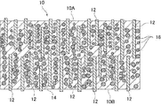
- FIG. 1 is a heat conductive sheet according to one embodiment of the present invention.
- FIG. 1 shows an example in which the anisotropic filler is typically a fiber material.
- the heat conductive sheet 10 includes an anisotropic filler 12 in a polymer matrix 14, and the surfaces 10 ⁇ / b> A and 10 ⁇ / b> B have a peak at the top while the anisotropic filler 12 is exposed.
- the arithmetic mean tune (Spc) is 18000 (1 / mm) or less.
- the arithmetic mean tune (Spc) of the peaks is 18000 (1 / mm).
- the sheet surface 10A has smoothness, the contact area in close contact with the heating element or the like is increased, and the thermal resistance value can be reduced.
- the arithmetic mean tune (Spc) at the peak is preferably 17000 (1 / mm) or less, more preferably 16000 (1 / mm) or less.
- the arithmetic mean tune (Spc) at the peak is preferably 1000 (1 / mm) or more, more preferably 5000 (1 / mm) or more.
- the arithmetic mean tune (Spc) at the peak is a parameter that is measured according to ISO25178 and represents the arithmetic average of the main curvature of the peak in the definition area. A small value indicates that the point in contact with the heating element or the like is rounded. On the other hand, a large value indicates that the point in contact with the heating element or the like is sharp.
- the position of the rounded contact point is not known, but, for example, the end or end face of the anisotropic filler exposed on the surface, or the end of the anisotropic filler and the surface of the polymer matrix. May be rounded contact points.
- the arithmetic mean tune (Spc) at the peak can be calculated by measuring the surface profile of a predetermined measurement area (for example, a two-dimensional area of 1 mm 2 ) with a commercially available laser microscope.
- a polishing paper having a grain size of # 120 to 20,000 is used, and the number of times of polishing is set appropriately according to the grain size. Processing may be performed. Further, if necessary, the E-hardness of the oriented molded body before being made into the heat conductive sheet 10 may be set to about 10 to 80, sliced into a sheet shape, and subjected to the above-mentioned polishing treatment.
- the anisotropic filler 12 is oriented at least inside the heat conductive sheet 10 in the thickness direction of the heat conductive sheet 10.
- the heat conductive sheet 10 has a high heat conductivity in the thickness direction, and has a smooth sheet surface and a low heat resistance value.
- a treatment such as a magnetic field orientation and a flow orientation described below may be performed.
- the state in which the anisotropic filler 12 is oriented in the thickness direction of the heat conductive sheet 10 means that the major axis direction of the anisotropic filler 12 exceeding 60% in number ratio is the heat conductive sheet. 10 means a state in which the film is oriented within a range of 20 ° or less from the thickness direction. Such a state of orientation can be confirmed by observing a cross section along the thickness direction of the heat conductive sheet 10 with an electron microscope.
- the arithmetic mean height (Sa) of the surface 10A of the heat conductive sheet 10 is preferably 20 ⁇ m or less, more preferably 1 to 15 ⁇ m.
- the arithmetic mean height (Sa) can be measured using a commercially available surface texture measuring instrument, and specifically, can be measured by the method described in Examples.
- a relatively coarse-grained abrasive paper having a grain size of # 120 to 20,000 is used, and the number of polishing according to the grain size is appropriately set, and Polishing may be performed.
- the surface 10A of the heat conductive sheet 10 preferably has an interface development area ratio (Sdr) of 70 or less, more preferably 1 to 60. Even if the heat conductive filler is exposed from the surface 10A of the heat conductive sheet 10 and the sheet surface is uneven, the spread area ratio (Sdr) of the interface is 70 or less, so that the sheet surface has smoothness. And the contact area in close contact with the heating element or the like is increased, and the thermal resistance value can be reduced.
- Sdr interface development area ratio
- the developed area ratio (Sdr) of the interface is an index indicating how much the developed area (surface area) of the defined area increases with respect to the area of the defined area (for example, 1 mm 2 ), and is completely flat.
- the development area ratio Sdr is 0 for the appropriate surface.
- the interface development area ratio (Sdr) can be measured by the method described in Examples.
- the interface development area ratio (Sdr) for example, a relatively coarse abrasive paper among abrasive papers having a grain size of # 120 to 20,000 is used, and the number of polishing according to the grain size is appropriately set.
- the surface may be polished.
- the heat conductive sheet 10 further contains a non-anisotropic filler 16.
- the thermal conductivity of the heat conductive sheet 10 is further improved by containing the non-anisotropic filler 16. Details of the non-anisotropic filler 16 will be described later.
- the polymer matrix 14 used in the heat conductive sheet 10 is a polymer compound such as an elastomer or rubber, and is preferably a liquid polymer composition (a curable polymer) composed of a mixed system such as a base material and a curing agent. Composition) is preferably used after curing.
- the curable polymer composition may be composed of, for example, an uncrosslinked rubber and a crosslinking agent, or may contain a monomer, a prepolymer, and the like, and a curing agent.
- the curing reaction may be room temperature curing or thermal curing.
- Silicone rubber is exemplified as the polymer matrix 14 formed from the curable polymer composition.
- the polymer matrix (curable polymer composition) 14 an addition reaction-curable silicone is preferably used. More specifically, a curable polymer composition containing an alkenyl group-containing organopolysiloxane and a hydrogen organopolysiloxane may be used.
- the rubber various synthetic rubbers other than the above can be used, and specific examples include, for example, acrylic rubber, nitrile rubber, isoprene rubber, urethane rubber, ethylene propylene rubber, styrene / butadiene rubber, butadiene rubber, and fluorine. Rubber and butyl rubber.
- the synthetic rubber may be crosslinked or uncrosslinked (that is, uncured) in the heat conductive sheet. Uncrosslinked rubber is mainly used in flow orientation.
- crosslinked (that is, cured) as described above, the polymer matrix is obtained by curing a curable polymer composition comprising an uncrosslinked rubber composed of these synthetic rubbers and a crosslinking agent. And it is sufficient.
- thermoplastic elastomer such as a polyester-based thermoplastic elastomer or a polyurethane-based thermoplastic elastomer, or a thermosetting elastomer formed by curing a mixed liquid polymer composition comprising a main agent and a curing agent is used.
- a polyurethane elastomer formed by curing a polymer composition containing a polymer having a hydroxyl group and an isocyanate can be exemplified.
- silicone rubber particularly an addition-reaction-curable silicone, for example, because the polymer matrix after curing is particularly flexible and the heat-conductive filler has good filling properties.
- the polymer composition for forming the polymer matrix may be composed of a polymer compound alone, or may be composed of a polymer compound and a plasticizer.
- the plasticizer is suitably used when using synthetic rubber, and by including the plasticizer, it is possible to increase the flexibility of the polymer matrix when not cross-linked.
- the content of the polymer matrix is preferably 20 to 50% by volume, more preferably 25 to 45% by volume, based on the total amount of the thermally conductive sheet, expressed in terms of a volume-based filling rate (volume filling rate).
- additives may be further added to the polymer matrix 14 within a range that does not impair the function as the heat conductive sheet 10.
- the additive include at least one selected from a dispersant, a coupling agent, a pressure-sensitive adhesive, a flame retardant, an antioxidant, a coloring agent, an anti-settling agent, and the like.
- a crosslinking accelerator for promoting crosslinking and curing, a curing accelerator, or the like may be blended as an additive.
- the anisotropic filler 12 blended in the polymer matrix 14 is a filler having anisotropy in shape, and is an orientable filler.
- the anisotropic filler 12 is preferably a heat conductive filler.
- a fibrous filler for example, a fibrous material such as carbon fiber
- a flaky filler a flaky material such as graphite, graphene, and boron nitride
- these anisotropic fillers are exposed on the surface of the heat conductive sheet 10 and the sheet surface is small and uneven, the sheet surface has good smoothness and the contact area in close contact with the heating element or the like is small. It becomes wider and the thermal resistance value can be further reduced.
- the anisotropic filler 12 has a high aspect ratio, specifically, an aspect ratio exceeding 2, and preferably has an aspect ratio of 5 or more. When the aspect ratio is larger than 2, the anisotropic filler 12 is easily oriented in the thickness direction, and the thermal conductivity of the thermally conductive sheet 10 is easily increased.
- the upper limit of the aspect ratio is not particularly limited, but is practically 100.
- the aspect ratio is the ratio of the length in the major axis direction to the length in the minor axis direction of the anisotropic filler, and in a fibrous material, means fiber length / diameter of a fiber, and in a flaky material. Means the length / thickness of the flaky material in the major axis direction.
- the anisotropic filler is preferably a fiber material from the viewpoint of increasing thermal conductivity.
- the content of the anisotropic filler 12 in the heat conductive sheet is preferably from 30 to 500 parts by mass, more preferably from 50 to 300 parts by mass, per 100 parts by mass of the polymer matrix.
- the content of the anisotropic filler 12 is preferably 5 to 60% by volume, more preferably 8 to 45% by volume based on the total amount of the thermally conductive sheet, expressed as a volume-based filling rate (volume filling rate). % By volume.
- the average fiber length is preferably 50 to 500 ⁇ m, more preferably 70 to 350 ⁇ m.
- the anisotropic fillers 12 appropriately contact each other inside the heat conductive sheet 10 to secure a heat transmission path.
- the average fiber length is 500 ⁇ m or less, the bulk of the anisotropic filler 12 decreases, and the polymer matrix can be highly filled.
- the average fiber length of the fiber material is preferably shorter than the thickness of the heat conductive sheet 10. By being shorter than the thickness, it is possible to prevent the fiber material from unnecessarily protruding from the surface of the heat conductive sheet 10.
- the average particle size is preferably from 10 to 400 ⁇ m, more preferably from 15 to 200 ⁇ m. Further, the thickness is particularly preferably from 15 to 130 ⁇ m. By setting the average particle size to 10 ⁇ m or more, the anisotropic fillers 12 in the heat conductive sheet are easily brought into contact with each other, and a heat transfer path is secured.
- the average particle size is 400 ⁇ m or less, the bulk of the heat conductive sheet 10 is reduced, and the polymer matrix 14 can be filled with the anisotropic filler 12 at a high level.
- the average fiber length of the carbon fiber and the average particle size of the flaky material can be calculated from, for example, the fiber length and the long diameter by observing the anisotropic filler with a microscope. More specifically, for example, the fiber length and the major axis of 50 arbitrary anisotropic fillers are measured using an electron microscope or an optical microscope, and the average value (arithmetic average value) is calculated as the average fiber length or average. Particle size can be used.
- the anisotropic filler 12 a known material having thermal conductivity may be used. However, it is preferable that the anisotropic filler 12 has diamagnetism so that a magnetic field can be oriented as described later.
- Specific examples of the anisotropic filler 12 include carbon fibers, carbon-based materials typified by flaky carbon powder, metal materials and metal oxides typified by metal fibers, boron nitride, metal nitrides, and metal carbides. And metal hydroxides.
- a carbon-based material is preferable because of its low specific gravity and good dispersibility in the polymer matrix 14, and a graphitized carbon material having a high thermal conductivity is more preferable.
- the graphitized carbon material has diamagnetism when the graphite surfaces are aligned in a predetermined direction. Further, boron nitride and the like also have diamagnetism when the crystal planes are aligned in a predetermined direction.
- the anisotropic filler 12 is not particularly limited, but generally has a thermal conductivity of 60 W / m ⁇ K or more, preferably 400 W, in a direction having anisotropy (that is, a major axis direction). / M ⁇ K or more.
- the upper limit of the thermal conductivity of the anisotropic filler 12 is not particularly limited, but is, for example, 2000 W / m ⁇ K or less.
- the thermal conductivity can be measured by a laser flash method or a method based on ASTM D5470.
- the anisotropic filler 12 may be used alone or in combination of two or more.
- an anisotropic filler 12 having at least two different average particle diameters or average fiber lengths may be used as the anisotropic filler 12.
- the small anisotropic fillers 12 enter between the relatively large anisotropic fillers 12 so that the anisotropic fillers 12 are contained in the polymer matrix. It is thought that the heat transfer efficiency can be increased while filling at high density.
- the carbon fibers used as the anisotropic filler 12 are preferably graphitized carbon fibers.
- flaky carbon powder flaky graphite powder is preferable.
- the anisotropic filler is more preferably a graphitized carbon fiber.
- Graphitized carbon fibers have graphite crystal faces connected in the fiber axis direction, and have high thermal conductivity in the fiber axis direction. Therefore, by aligning the fiber axis direction with a predetermined direction, the thermal conductivity in a specific direction can be increased.
- the flaky graphite powder has a graphite crystal plane continuous in the in-plane direction of the flake surface, and has high thermal conductivity in the in-plane direction. Therefore, by aligning the scale surfaces in a predetermined direction, the thermal conductivity in a specific direction can be increased.
- Graphitized carbon fibers and flake graphite powder preferably have a high degree of graphitization.
- the graphitized carbon material such as the graphitized carbon fiber and the flaky graphite powder
- the following raw materials can be used.
- condensed polycyclic hydrocarbon compounds such as naphthalene, condensed heterocyclic compounds such as PAN (polyacrylonitrile), pitch and the like
- PAN polyacrylonitrile
- the pitch is oriented in the fiber axis direction due to its anisotropy, and graphitized carbon fibers having excellent thermal conductivity in the fiber axis direction can be obtained.
- Graphitized carbon fiber is obtained by subjecting raw materials to spinning, infusibilization, and carbonization in order, pulverized or cut to a predetermined particle size and then graphitized, or carbonized after pulverized or cut after carbonization. Can be used. When pulverized or cut before graphitization, the polycondensation reaction and cyclization reaction can easily proceed during the graphitization treatment on the surface newly exposed by pulverization. Graphitized carbon fibers with improved properties can be obtained.
- the graphitized carbon fiber is so stiff that the pulverized carbon fiber is easily pulverized, and can be pulverized for a short time to obtain a carbon fiber powder having a relatively narrow fiber length distribution.
- the non-anisotropic filler 16 is a thermally conductive filler contained in the thermally conductive sheet 10 separately from the anisotropic filler 12, and is thermally conductive to the thermally conductive sheet 10 together with the anisotropic filler 12. It is a material that imparts properties. In the present embodiment, by filling the non-anisotropic filler 16, an increase in viscosity is suppressed before the sheet is cured, and the dispersibility is improved. In addition, in the anisotropic fillers 12, for example, it is difficult to increase the contact area between the fillers when the fiber length is increased, but by filling the gap with the non-anisotropic filler 16, a heat transfer path can be formed.
- the heat conductive sheet 10 having high heat conductivity is obtained.
- the non-anisotropic filler 16 is a filler having substantially no anisotropy in shape, and the anisotropic filler 12 is oriented in a predetermined direction, such as under the generation of magnetic lines of force or under the action of shearing force, which will be described later. It is a filler that is not oriented in a predetermined direction even under an environment.
- the non-anisotropic filler 16 has an aspect ratio of 2 or less, and preferably 1.5 or less.
- the filler having thermal conductivity is appropriately interposed between the gaps of the anisotropic filler 12, and the thermal conductivity is reduced. Is obtained.
- the aspect ratio is set to 2 or less, it is possible to prevent the viscosity of the mixed composition described later from increasing and to achieve high filling.
- non-anisotropic filler 16 examples include, for example, metals, metal oxides, metal nitrides, metal hydroxides, carbon materials, oxides other than metals, nitrides, and carbides.
- shape of the non-anisotropic filler examples include spherical and amorphous powders.
- the metal is exemplified by aluminum, copper, nickel, etc.
- the metal oxide is exemplified by aluminum oxide (alumina), magnesium oxide, zinc oxide, etc.
- the metal nitride is exemplified by aluminum nitride. be able to.
- the metal hydroxide examples include aluminum hydroxide.
- the non-anisotropic filler 16 is preferably selected from the group consisting of alumina, aluminum, zinc oxide, boron nitride, and aluminum nitride, and aluminum and alumina are particularly preferable from the viewpoint of filling properties and thermal conductivity. Alumina is more preferred.
- the non-anisotropic filler 16 one of the above-described materials may be used alone, or two or more may be used in combination.
- the average particle size of the non-anisotropic filler 16 is preferably 0.1 to 50 ⁇ m, and more preferably 0.5 to 35 ⁇ m. It is particularly preferable that the thickness be 1 to 15 ⁇ m. When the average particle size is 50 ⁇ m or less, problems such as disturbing the orientation of the anisotropic filler 12 are less likely to occur. Further, by setting the average particle size to 0.1 ⁇ m or more, the specific surface area of the non-anisotropic filler 16 does not become unnecessarily large, and the viscosity of the mixed composition does not easily increase even if it is added in a large amount. It becomes easy to highly fill the anisotropic filler 16.
- a non-anisotropic filler 16 having at least two different average particle sizes may be used as the non-anisotropic filler.
- the average particle size of the non-anisotropic filler 16 can be measured by observing with an electron microscope or the like. More specifically, for example, the particle diameter of 50 arbitrary non-anisotropic fillers is measured using an electron microscope or an optical microscope, and the average value (arithmetic average value) is used as the average particle diameter. Can be.
- the average particle size is a volume average particle size of a particle size distribution measured by a laser diffraction scattering method (JIS R1629).
- the content of the non-anisotropic filler 16 is preferably in the range of 200 to 800 parts by mass, more preferably in the range of 300 to 700 parts by mass, based on 100 parts by mass of the polymer matrix.
- the content of the non-anisotropic filler 16 is preferably from 30 to 60% by volume, more preferably from 40 to 55% by volume, based on the volume-based filling rate (volume filling rate), based on the total amount of the thermally conductive sheet. preferable.
- the amount of the non-anisotropic filler is 200 parts by mass or more, the amount of the non-anisotropic filler 16 interposed in the gap between the anisotropic fillers 12 is sufficient, and the thermal conductivity is improved.
- the content is 800 parts by mass or less, the effect of increasing the thermal conductivity according to the content can be obtained, and the heat conduction by the anisotropic filler 12 is inhibited by the non-anisotropic filler 16. I do not even do. Further, when the content is in the range of 300 to 700 parts by mass, the heat conductivity of the heat conductive sheet 10 is excellent, and the viscosity of the mixed composition becomes suitable.
- the ratio of the volume filling rate of the non-anisotropic filler 16 to the volume filling rate of the anisotropic filler is preferably 2 to 5, more preferably 2 to 3.
- the non-anisotropic filler 16 is appropriately filled between the anisotropic fillers, and an efficient heat transfer path can be formed. Therefore, the heat conductivity of the heat conductive sheet 10 can be improved.
- the thermal resistance value of the heat conductive sheet 10 in the thickness direction of the sheet is preferably less than 1 ° C / W, more preferably 0.5 ° C / W or less, further preferably 0.2 ° C / W or less.
- the thermal resistance can be measured by the method described in the examples.
- the thermal conductivity of the heat conductive sheet 10 in the thickness direction is, for example, 5 W / m ⁇ K or more, preferably 10 W / m ⁇ K or more, more preferably 15 W / m ⁇ K or more, and 18 W / m. -K or more is more preferable.
- the heat conductivity in the thickness direction of the heat conductive sheet 10 can be made excellent.
- the thermal conductivity in the thickness direction of the thermally conductive sheet 10 is, for example, 50 W / m ⁇ K or less.
- the thermal conductivity shall be measured by a method according to ASTM D5470-06.
- the surface of the heat conductive sheet 10 becomes a non-adhesive surface by exposing the anisotropic filler 12 on the surface as described above.
- the surface that is a non-adhesive surface is hardly adhered even when touched by an operator's hand, and is easily peeled off even if it is attached to a contact target such as a heating element or a heat radiator described below by pressing. Further, since the surface of the heat conductive sheet 10 is non-adhesive, it can be slid when assembled to an electronic device or the like.
- the thickness of the heat conductive sheet 10 is considered to be used in the range of 0.1 to 5.0 m, but it is not necessary to be limited to the thickness range. Although the thickness is appropriately changed depending on the shape and use of the electronic device on which the heat conductive sheet 10 is mounted, a more preferable thickness is 0.1 to 0.3 mm. When the thickness is 0.1 to 0.3 mm, the heat conductive sheet becomes a thin film and becomes a heat conductive sheet that easily conducts heat.
- the heat conductive sheet 10 is used inside an electronic device or the like. Specifically, the heat conductive sheet is interposed between the heat generating element and the heat radiator, and conducts heat generated by the heat generating element to move the heat to the heat radiator and radiate the heat from the heat radiator.
- the heating element include various electronic components such as a CPU, a power amplifier, and a power supply such as a battery used in the electronic device.
- the heat radiator include a heat sink, a heat pipe, a heat pump, and a metal housing of an electronic device.
- the heat conductive sheet is used in a state where both surfaces are in close contact with the heat generating body and the heat radiating body, respectively, and are compressed.
- the heat conductive sheet of the present embodiment can be manufactured by, for example, a method including the following steps (A), (B), and (C).
- an oriented molded body is formed from a mixed composition including an anisotropic filler, a non-anisotropic filler, and a polymer composition serving as a raw material of a polymer matrix.
- the mixed composition is preferably cured to form an oriented molded article.
- the oriented molded body can be obtained by a magnetic field orientation production method or a flow orientation production method. Among these, the magnetic field orientation production method is preferable.
- Magnetic orientation method In the magnetic field orientation method, a mixed composition containing a liquid polymer composition, which becomes a polymer matrix after curing, and an anisotropic filler and a non-anisotropic filler, is injected into a mold or the like, and then subjected to a magnetic field. Then, after orienting the anisotropic filler along the magnetic field, the polymer composition is cured to obtain an oriented molded article. It is preferable that the oriented molded body is in a block shape. In addition, a release film may be disposed in a portion of the mold that comes into contact with the mixed composition.
- the release film for example, a resin film having good releasability or a resin film having one surface subjected to a release treatment with a release agent or the like is used.
- the release film By using the release film, the oriented molded article is easily released from the mold.
- the viscosity of the mixed composition used in the magnetic field orientation method is preferably from 10 to 300 Pa ⁇ s for magnetic field orientation.
- the pressure is 10 Pa ⁇ s or more, the anisotropic filler and the non-anisotropic filler are less likely to settle.
- the pressure is 300 Pa ⁇ s or less, the fluidity is improved, and the anisotropic filler is appropriately oriented by the magnetic field, and there is no problem that the orientation takes too much time.
- the viscosity is a viscosity measured at 25 ° C. at a rotation speed of 10 rpm using a rotational viscometer (Brookfield viscometer DV-E, spindle SC4-14).
- the viscosity of the mixed composition may be less than 10 Pa ⁇ s. .
- a superconducting magnet As a magnetic field line source for applying magnetic field lines, a superconducting magnet, a permanent magnet, an electromagnet and the like can be mentioned, but a superconducting magnet is preferable in that a magnetic field with a high magnetic flux density can be generated.
- the magnetic flux density of the magnetic field generated from these magnetic field generating sources is preferably 1 to 30 Tesla.
- the magnetic flux density is 1 Tesla or more, the above-described anisotropic filler made of a carbon material or the like can be easily oriented.
- the curing of the polymer composition is preferably performed by heating, but is preferably performed at a temperature of, for example, about 50 to 150 ° C.
- the heating time is, for example, about 10 minutes to 3 hours.
- Flow orientation method In the flow orientation manufacturing method, a shear force is applied to the mixed composition to produce a preliminary sheet in which the anisotropic filler is oriented in the plane direction, and a plurality of the sheets are laminated to produce a laminated block, and the laminated block is produced.
- the block may be an oriented molded body. More specifically, in the flow orientation manufacturing method, first, the polymer composition is mixed with an anisotropic filler and a non-anisotropic filler, and if necessary, various additives and stirred, and the mixed solid is homogeneous. To prepare a mixed composition.
- the polymer compound used in the polymer composition may include a polymer compound that is liquid at normal temperature (23 ° C.), or may include a polymer compound that is solid at normal temperature. Is also good.
- the polymer composition may contain a plasticizer.
- the mixed composition has a relatively high viscosity so that a shearing force is applied when the mixed composition is stretched into a sheet, and the viscosity of the mixed composition is specifically preferably 3 to 50 Pa ⁇ s.
- the mixed composition is preferably mixed with a solvent in order to obtain the above viscosity.
- the mixed composition is formed into a sheet (preliminary sheet) by stretching it flat while applying a shearing force.
- a shearing force By applying a shearing force, the anisotropic filler can be oriented in the shearing direction.
- a sheet forming means for example, an application applicator such as a bar coater or a doctor blade, or by extrusion or ejection from a nozzle, etc., apply the mixed composition onto the base film, and then, if necessary, It is preferable to dry or semi-cur the mixed composition.
- the thickness of the preliminary sheet is preferably about 50 to 250 ⁇ m.
- the anisotropic filler is oriented in one direction along the plane of the sheet.
- the preliminary sheets are mutually bonded by heat pressing or the like while the mixed composition is cured as necessary by heating, ultraviolet irradiation, or the like. It is preferable that a laminated block is formed by bonding, and the laminated block is an oriented molded body.
- Step (B) the oriented molded article obtained in the step (A) is cut by slicing or the like perpendicular to the direction in which the anisotropic filler is oriented to obtain a sheet-shaped molded article.
- Slicing may be performed with, for example, a shearing blade or a laser.
- the leading end of the anisotropic filler is exposed from the polymer matrix on each surface as a cut surface by cutting such as slicing. At least a part of the exposed anisotropic filler protrudes from each surface. Most of the exposed anisotropic filler is oriented in the thickness direction without falling down.
- the oriented molded article preferably has a type E hardness of 10 to 80, more preferably 20 to 70, as defined in JIS K6253.
- E hardness 10 to 80
- the polymer matrix is more actively cut than the anisotropic filler when slicing the sheet-shaped molded body, so that the anisotropic filler is easily exposed.
- polishing the surface also exposes the anisotropic filler because the polymer matrix is easier to wear than the anisotropic filler. Can be.
- the anisotropic filler is worn while exposed, the exposed end of the anisotropic filler is crushed, and the end of the thermally conductive sheet swelling in the surface direction is easily formed. Since the contact area between the end portion and the adherend increases, the thermal conductivity can be further improved.
- Step (C) the surface of the sheet-like molded body where the anisotropic filler is exposed is polished. Polishing of the surface may be performed using, for example, polishing paper, a polishing film, a polishing cloth, a polishing belt, or the like.
- the arithmetic mean tune (Spc) at the peak of the peak is set to 18000 (1 / mm) or less while the anisotropic filler is exposed by polishing the surface of the sheet-shaped molded body.
- the properties of the abrasive paper are preferably those having an average particle diameter (D50) of 0.1 to 100 ⁇ m, more preferably 9 to 60 ⁇ m.
- the arithmetic mean tune (Spc) at the peak of the peak is smoothed to a predetermined value or less while the anisotropic filler is exposed from the sheet surface.
- the point of contact with the contact partner surface such as a heating element is rounded and can be smoothed.
- abrasive paper having an average particle size of 100 ⁇ m or less it is possible to prevent the surface of the heat conductive sheet from being scratched, which is a practical problem.
- the grain size of the abrasive grains of the abrasive paper is preferably from $ 120 to 20,000, more preferably from $ 300 to 15000, and even more preferably from $ 320 to 4,000.
- the polishing method is, for example, polishing the surface of the heat conductive sheet by continuously abutting polishing paper in the same linear direction, polishing a predetermined distance back and forth, or polishing by rotating in the same direction. Or polishing in contact with various directions.
- the degree of polishing may be performed while observing the surface condition.
- the reciprocation is preferably performed 1 to 300 times, more preferably 2 to 200 times, and further preferably 3 to 50 times. More specifically, it is preferable that the polishing is performed so that the protruding length of the anisotropic filler becomes 100 ⁇ m or less. Further, it is more preferable that the protrusion is polished to a length of 50 ⁇ m or less.
- the anisotropic filler 12 is exposed on both surfaces 10A and 10B of the heat conductive sheet 10, and the anisotropic filler 12 is exposed on both surfaces 10A and 10B.
- the arithmetic mean tune (Spc) is 18000 (1 / mm) or less.
- the anisotropic filler 12 is exposed and the arithmetic mean tune (Spc) at the peak is 18000 (1 / mm) or less.
- the arithmetic mean tune (Spc) at the peak of the mountain may not be less than 18000 (1 / mm).
- the polishing in the step (C) is performed on only one of the two surfaces, and the other surface is not polished. It is good to do.
- the polished one is very flat before being used in close contact with the heating element and the heat radiating element and compressed, and the surface properties after compression are almost flattened slightly before compression. does not change.
- those which are not polished may be significantly flattened by compression, but cannot be flattened to the same degree as polished ones.
- the other of the surfaces 10A and 10B may be a surface in which the anisotropic filler 12 is embedded in the polymer matrix 12.
- the oriented molded body produced by the magnetic field orientation method described above has an outermost surface, in which the filling ratio of the anisotropic filler is lower than other portions, typically, a skin layer containing no anisotropic filler. Becomes Therefore, for example, by setting the outermost surface of the oriented molded body to the other of the two surfaces 10A and 10B of the heat conductive sheet 10, the other of the two surfaces 10A and 10B is replaced by the anisotropic filler 12.
- a surface buried inside the polymer matrix 12 can be formed.
- the surface in which the anisotropic filler 12 is embedded inside the polymer matrix 12 becomes an adhesive surface.
- the adhesive surface can fix the contact object by attaching to the contact object such as a heat radiator or a heating element.
- the heat conductive sheet 10 contains the non-anisotropic filler 16 in addition to the anisotropic filler 12 as the filler.
- the non-anisotropic filler 20 does not contain the non-anisotropic filler 16 as shown in FIG. That is, in the heat conductive sheet of the second embodiment, for example, only carbon fibers may be used as the filler.
- Other configurations of the heat conductive sheet 20 of the second embodiment are the same as the heat conductive sheet 10 of the first embodiment described above, except that the non-anisotropic filler is not contained. Description is omitted.
- At least one of the surfaces 20A and 20B of the heat conductive sheet 20 has a configuration in which the anisotropic filler 12 is exposed, and is similar to the first embodiment. The effect of is obtained.
- At least one surface has an arithmetic mean tune (Spc) at the peak of the peak of 18000 (1 / mm) or less while the anisotropic filler 12 is exposed.
- Spc arithmetic mean tune
- the physical properties of the heat conductive sheet were evaluated by the following methods.
- Spc Arithmetic Average Height
- Sa Interface Expansion Area Ratio
- the surface property was analyzed using a laser microscope (VK-X150, manufactured by Keyence Corporation) in accordance with ISO25178. Specifically, the surface profile of a two-dimensional area having a lens magnification of 10 and a surface area of 1000 ⁇ m ⁇ 1000 ⁇ m was measured by a laser method. The average value measured at three locations on the same sample was adopted as the arithmetic mean tune Spc at the peak.
- the arithmetic average height (Sa) and the interface development area ratio (Sdr) were measured at three locations for the same sample, and the average values were calculated for the arithmetic average height (Sa) and interface development, respectively.
- the area ratio (Sdr) was used.
- the thermal resistance value was measured by a method shown below using a thermal resistance measuring machine as shown in FIG. Specifically, for each sample, a test piece S having a size of 30 mm ⁇ 30 mm was prepared for the main test. Then, each test piece S is stuck on a copper block 22 having a measurement surface of 25.4 mm ⁇ 25.4 mm and side surfaces covered with a heat insulating material 21, sandwiched by an upper copper block 23, and a load is applied by a load cell 26. The thickness was set to be 90% of the original thickness.
- the lower copper block 22 is in contact with the heater 24.
- the upper copper block 23 is covered with a heat insulating material 21 and connected to a heat sink 25 with a fan.
- the heater 24 is caused to generate heat at a heating value of 25 W.
- the temperature of the upper copper block 23 ( ⁇ j0 ), the temperature of the lower copper block 22 ( ⁇ j1 ), and the temperature of the heater
- the calorific value (Q) was measured, and the thermal resistance of each sample was determined from the following equation (1).
- Thermal resistance ( ⁇ j1 ⁇ j0 ) / Q (1)
- ⁇ j1 is the temperature of the lower copper block 22
- ⁇ j0 is the temperature of the upper copper block 23
- Q is the calorific value.
- Type E hardness specified in JIS K6253 Type E hardness was measured based on Japanese Industrial Standard JIS K6253. Specifically, the orientation molded body produced in each example was measured using a type E durometer.
- Example 1 Alkenyl group-containing organopolysiloxane and hydrogen organopolysiloxane (total 100 parts by mass, volume filling rate 36% by volume) as a polymer matrix (polymer composition), and carbon fibers (average fiber 150 parts by mass (graphitized carbon fiber having a length of 100 ⁇ m, an aspect ratio of 10, and a thermal conductivity of 500 W / m ⁇ K) (volume filling rate of 30 vol%), and alumina powder (spherical, average particle size) as a non-anisotropic filler 3 ⁇ m, aspect ratio 1.0) 200 parts by mass (volume filling rate 18% by volume) and 100 parts by mass (volume filling rate 13% by volume) of aluminum powder (amorphous, average particle size 3 ⁇ m) are mixed.
- carbon fibers average fiber 150 parts by mass (graphitized carbon fiber having a length of 100 ⁇ m, an aspect ratio of 10, and a thermal conductivity of 500 W / m ⁇ K) (volume filling
- both surfaces of the sheet-like molded body were reciprocally polished 50 times with coarse abrasive paper A (particle size # 320) having an average particle diameter (D50) of 60 ⁇ m, to obtain a heat conductive sheet. .
- Example 2 Same as Example 1 except that the polishing paper A was changed to polishing paper B (grain size # 4000) having finer abrasive grains and an average particle diameter (D50) of 3 ⁇ m, and the number of polishing was changed to 15 reciprocations. Thus, a heat conductive sheet was obtained.
- Example 3 Except that the polishing paper A was changed to polishing paper C (grain size # 15000) having even finer abrasive grains and an average particle diameter (D50) of 0.3 ⁇ m, and the number of polishing was changed to three reciprocations, A heat conductive sheet was obtained in the same manner as in Example 1.
- Example 1 was the same as Example 1 except that the 50-way reciprocating polishing with the polishing paper A was changed to the 30-reciprocating polishing with the polishing paper A, then the reciprocating polishing was repeated 10 times with the polishing paper B, and further 10 times with the polishing paper C. Similarly, a heat conductive sheet was obtained.
- Example 1 A heat conductive sheet was obtained in the same manner as in Example 1, except that the sheet-like molded body was not polished.
- Example 5 Alkenyl group-containing organopolysiloxane and hydrogen organopolysiloxane (total 100 parts by mass, volume filling rate 32% by volume) as a polymer matrix (polymer composition), and carbon fibers (average fiber 150 parts by mass (graphitized carbon fiber having a length of 100 ⁇ m, an aspect ratio of 10, and a thermal conductivity of 500 W / m ⁇ K) (volume filling rate of 26 vol%), and alumina powder (spherical, average particle size) as a non-anisotropic filler 475 parts by mass (volume filling rate: 41% by volume) of 3 ⁇ m and an aspect ratio of 1.0 were mixed to obtain a mixed composition.
- the matrix was cured by heating at 80 ° C. for 60 minutes to obtain a block-shaped oriented molded body.
- the block-shaped oriented molded body was sliced into a sheet having a thickness of 1 mm using a shear blade to obtain a sheet-shaped molded body in which the carbon fibers were exposed.
- both surfaces of the sheet-shaped molded body were polished and reciprocated 30 times with abrasive paper A having coarse abrasive grains to obtain a thermally conductive sheet.
- Example 6 A thermally conductive sheet was obtained in the same manner as in Example 5, except that the polishing paper A was changed to polishing paper B having finer abrasive grains and the number of polishing was changed to 15 reciprocations.
- Example 7 A thermally conductive sheet was obtained in the same manner as in Example 5, except that the polishing paper A was changed to polishing paper C having finer abrasive grains, and the number of times of polishing was changed to five reciprocations.
- Example 8 Example 5 was repeated except that the 50 reciprocal polishing with the polishing paper A was changed to the 30 reciprocal polishing with the polishing paper A, and then the polishing paper B was changed to the 10 reciprocal polishing and the polishing paper C was changed to the 10 reciprocal polishing. Similarly, a heat conductive sheet was obtained.
- Example 9 Alkenyl group-containing organopolysiloxane and hydrogen organopolysiloxane (total 100 parts by mass, volume filling rate 36% by volume) as a polymer matrix (polymer composition), and carbon fibers (average fiber 140 parts by mass (volume filling rate: 28% by volume) of graphite (average particle diameter: 130 ⁇ m, aspect ratio: 10, aspect ratio: 10, thermal conductivity: 550 W / 100 ⁇ m, graphitized carbon fiber having an aspect ratio of 10, and a thermal conductivity of 500 W / m ⁇ K) 5 mass parts (volume filling rate: 1% by volume) of aluminum powder (irregular, average particle size: 3 ⁇ m) 250 mass parts (volume filling rate: 34 vol.) %) was mixed to obtain a mixed composition.
- graphite average particle diameter: 130 ⁇ m, aspect ratio: 10, aspect ratio: 10, thermal conductivity: 550 W / 100 ⁇ m, graphitized carbon fiber having an aspect ratio of 10, and a thermal conductivity
- the matrix was cured by heating at 80 ° C. for 60 minutes to obtain a block-shaped oriented molded body.
- the block-shaped oriented molded body was sliced into a sheet having a thickness of 1 mm using a shear blade to obtain a sheet-shaped molded body in which the carbon fibers were exposed.
- both surfaces of the sheet-like molded body were reciprocally polished 50 times with coarse abrasive paper A (particle size # 320) having an average particle diameter (D50) of 60 ⁇ m, to obtain a heat conductive sheet. .
- Example 10 Same as Example 9 except that the polishing paper A was changed to polishing paper B (grain size # 4000) having finer abrasive grains and an average particle diameter (D50) of 3 ⁇ m, and the number of times of polishing was changed to 15 reciprocations. Thus, a heat conductive sheet was obtained.
- Example 11 Except that the polishing paper A was changed to polishing paper C (grain size # 15000) having even finer abrasive grains and an average particle diameter (D50) of 0.3 ⁇ m, and the number of polishing was changed to three reciprocations, In the same manner as in No. 9, a heat conductive sheet was obtained.
- Example 9 was the same as Example 9 except that the 50 reciprocal polishing with the polishing paper A was changed to the 30 reciprocal polishing with the polishing paper A, then the reciprocating polishing with the polishing paper B was repeated 10 times, and further the polishing paper C was changed to the 10 reciprocal polishing. Similarly, a heat conductive sheet was obtained.
- Example 13 Alkenyl group-containing organopolysiloxane and hydrogen organopolysiloxane (total 100 parts by mass, volume filling rate 36% by volume) as a polymer matrix (polymer composition), and carbon fibers (average fiber 150 parts by mass (graphitized carbon fiber having a length of 100 ⁇ m, an aspect ratio of 10, and a thermal conductivity of 500 W / m ⁇ K) (volume filling rate of 30% by volume), and aluminum powder (amorphous, average particle size) as a non-anisotropic filler. 250 parts by mass (diameter: 3 ⁇ m) (volume filling rate: 33% by volume) were mixed to obtain a mixed composition.
- the matrix was cured by heating at 80 ° C. for 60 minutes to obtain a block-shaped oriented molded body.
- the block-shaped oriented molded body was sliced into a sheet having a thickness of 1 mm using a shear blade to obtain a sheet-shaped molded body in which the carbon fibers were exposed.
- both surfaces of the sheet-shaped molded body were polished and reciprocated 30 times with abrasive paper A having coarse abrasive grains to obtain a thermally conductive sheet.
- Example 14 A thermally conductive sheet was obtained in the same manner as in Example 13, except that the polishing paper A was changed to polishing paper B having finer abrasive grains and the number of polishing was changed to 15 reciprocations.
- Example 15 A heat conductive sheet was obtained in the same manner as in Example 13, except that the polishing paper A was changed to polishing paper C having finer abrasive grains, and the number of times of polishing was changed to five reciprocations.
- Example 13 was the same as Example 13 except that the 50-way reciprocating polishing with the polishing paper A was changed to the 30-reciprocating polishing with the polishing paper A, then the reciprocating polishing was repeated 10 times with the polishing paper B, and the reciprocating polishing was further repeated 10 times with the polishing paper C. Similarly, a heat conductive sheet was obtained.
- the arithmetic mean tune (Spc) at the peak of the peak is 18000 (1 / mm) or less.
- the desired thermal resistance value and thermal conductivity could be obtained, and the thermal conductivity in the thickness direction could be improved.
- the desired thermal resistance value and the thermal conductivity could not be obtained, and the thermal conductivity in the thickness direction could not be sufficiently improved.
Landscapes
- Chemical & Material Sciences (AREA)
- Health & Medical Sciences (AREA)
- Chemical Kinetics & Catalysis (AREA)
- Medicinal Chemistry (AREA)
- Polymers & Plastics (AREA)
- Organic Chemistry (AREA)
- Physics & Mathematics (AREA)
- Thermal Sciences (AREA)
- Engineering & Computer Science (AREA)
- Microelectronics & Electronic Packaging (AREA)
- Cooling Or The Like Of Semiconductors Or Solid State Devices (AREA)
- Compositions Of Macromolecular Compounds (AREA)
- Cooling Or The Like Of Electrical Apparatus (AREA)
- Manufacture Of Macromolecular Shaped Articles (AREA)
Priority Applications (6)
| Application Number | Priority Date | Filing Date | Title |
|---|---|---|---|
| US17/278,420 US11987687B2 (en) | 2018-09-26 | 2019-09-25 | Heat conductive sheet |
| CN201980061521.9A CN112715059B (zh) | 2018-09-26 | 2019-09-25 | 导热片 |
| EP19865972.4A EP3860321B1 (en) | 2018-09-26 | 2019-09-25 | Heat conductive sheet |
| KR1020217008305A KR102761499B1 (ko) | 2018-09-26 | 2019-09-25 | 열전도성 시트 |
| JP2020549280A JP7618954B2 (ja) | 2018-09-26 | 2019-09-25 | 熱伝導性シート |
| JP2023184730A JP2023181341A (ja) | 2018-09-26 | 2023-10-27 | 熱伝導性シート |
Applications Claiming Priority (2)
| Application Number | Priority Date | Filing Date | Title |
|---|---|---|---|
| JP2018-180192 | 2018-09-26 | ||
| JP2018180192 | 2018-09-26 |
Publications (1)
| Publication Number | Publication Date |
|---|---|
| WO2020067141A1 true WO2020067141A1 (ja) | 2020-04-02 |
Family
ID=69949643
Family Applications (1)
| Application Number | Title | Priority Date | Filing Date |
|---|---|---|---|
| PCT/JP2019/037554 Ceased WO2020067141A1 (ja) | 2018-09-26 | 2019-09-25 | 熱伝導性シート |
Country Status (7)
| Country | Link |
|---|---|
| US (1) | US11987687B2 (https=) |
| EP (1) | EP3860321B1 (https=) |
| JP (2) | JP7618954B2 (https=) |
| KR (1) | KR102761499B1 (https=) |
| CN (1) | CN112715059B (https=) |
| TW (1) | TWI856026B (https=) |
| WO (1) | WO2020067141A1 (https=) |
Cited By (5)
| Publication number | Priority date | Publication date | Assignee | Title |
|---|---|---|---|---|
| JP2022068136A (ja) * | 2020-10-21 | 2022-05-09 | デクセリアルズ株式会社 | 熱伝導性シート及び熱伝導性シートの製造方法 |
| JPWO2022168961A1 (https=) * | 2021-02-05 | 2022-08-11 | ||
| WO2022176854A1 (ja) * | 2021-02-18 | 2022-08-25 | デクセリアルズ株式会社 | 熱伝導性シートの製造方法及び熱伝導性シート |
| WO2022210419A1 (ja) * | 2021-03-31 | 2022-10-06 | 積水ポリマテック株式会社 | 熱伝導性シートの製造方法 |
| CN116096792A (zh) * | 2020-09-30 | 2023-05-09 | 积水保力马科技株式会社 | 导热性片 |
Families Citing this family (2)
| Publication number | Priority date | Publication date | Assignee | Title |
|---|---|---|---|---|
| US12581949B2 (en) * | 2020-01-22 | 2026-03-17 | 3M Innovative Properties Company | Thermal interface layer |
| WO2021148916A1 (en) * | 2020-01-22 | 2021-07-29 | 3M Innovative Properties Company | Electrically conductive adhesive layer |
Citations (4)
| Publication number | Priority date | Publication date | Assignee | Title |
|---|---|---|---|---|
| JP2007326976A (ja) * | 2006-06-08 | 2007-12-20 | Polymatech Co Ltd | 熱伝導性成形体及びその製造方法 |
| JP2008251747A (ja) * | 2007-03-29 | 2008-10-16 | Polymatech Co Ltd | 熱伝導性シート |
| JP2018014534A (ja) | 2013-09-06 | 2018-01-25 | バンドー化学株式会社 | 熱伝導性樹脂成形品 |
| JP2018056315A (ja) | 2016-09-28 | 2018-04-05 | デクセリアルズ株式会社 | 電磁波吸収熱伝導シート、電磁波吸収熱伝導シートの製造方法及び半導体装置 |
Family Cites Families (22)
| Publication number | Priority date | Publication date | Assignee | Title |
|---|---|---|---|---|
| JPS6178389U (https=) | 1984-10-29 | 1986-05-26 | ||
| JP2001156227A (ja) * | 1999-11-30 | 2001-06-08 | Polymatech Co Ltd | 異方性熱伝導性シート |
| CN100404242C (zh) * | 2005-04-14 | 2008-07-23 | 清华大学 | 热界面材料及其制造方法 |
| JP4814550B2 (ja) | 2005-06-03 | 2011-11-16 | ポリマテック株式会社 | 熱伝導性成形体の製造方法 |
| JP5254870B2 (ja) * | 2009-04-22 | 2013-08-07 | ポリマテック株式会社 | 熱伝導性シート及びその製造方法 |
| JP5416174B2 (ja) * | 2011-07-08 | 2014-02-12 | ポリマテック株式会社 | 熱伝導性成形体 |
| JP5953160B2 (ja) | 2012-07-27 | 2016-07-20 | ポリマテック・ジャパン株式会社 | 熱伝導性成形体の製造方法 |
| JP6397229B2 (ja) | 2014-06-12 | 2018-09-26 | 国立研究開発法人産業技術総合研究所 | 厚み方向に高い熱伝導率を有する熱伝導性部材及び積層体 |
| JP6178389B2 (ja) | 2014-12-25 | 2017-08-09 | デクセリアルズ株式会社 | 熱伝導シートの製造方法、熱伝導シート、及び半導体装置 |
| CN107851623B (zh) | 2015-06-25 | 2021-04-16 | 积水保力马科技株式会社 | 导热片 |
| WO2016208509A1 (ja) * | 2015-06-25 | 2016-12-29 | コニカミノルタ株式会社 | 成形型、光学素子、及び光学素子の製造方法 |
| JP6524831B2 (ja) | 2015-07-16 | 2019-06-05 | 富士ゼロックス株式会社 | 情報処理装置及びプログラム |
| MY186397A (en) * | 2015-07-29 | 2021-07-22 | Namics Corp | Roughened copper foil, copper-clad laminate, and printed wiring board |
| JP2017135137A (ja) | 2016-01-25 | 2017-08-03 | 東洋紡株式会社 | 絶縁高熱伝導性シート、およびその製法、および積層体 |
| EP3419399B1 (en) * | 2016-04-11 | 2020-08-26 | Sekisui Polymatech Co., Ltd. | Heat conductive sheet |
| WO2017179416A1 (ja) | 2016-04-14 | 2017-10-19 | 三井金属鉱業株式会社 | 表面処理銅箔、キャリア付銅箔、並びにそれらを用いた銅張積層板及びプリント配線板の製造方法 |
| US10495788B2 (en) * | 2016-05-17 | 2019-12-03 | Canon Kabushiki Kaisha | Resin molded product, interchangeable lens for camera, and method of manufacturing resin molded product |
| JPWO2018123012A1 (ja) * | 2016-12-28 | 2019-10-31 | 日立化成株式会社 | 熱伝導シート、熱伝導シートの製造方法及び放熱装置 |
| CN108407425A (zh) * | 2018-02-11 | 2018-08-17 | 东莞市明骏智能科技有限公司 | 一种石墨烯-碳纳米管纤维基导热垫片及其制备方法 |
| WO2019244890A1 (ja) * | 2018-06-22 | 2019-12-26 | 積水ポリマテック株式会社 | 熱伝導性シート |
| JP7650071B2 (ja) * | 2019-09-30 | 2025-03-24 | 積水ポリマテック株式会社 | 熱伝導性シート及びその製造方法 |
| JP6892725B1 (ja) * | 2019-11-01 | 2021-06-23 | 積水ポリマテック株式会社 | 熱伝導性シート及びその製造方法 |
-
2019
- 2019-09-25 JP JP2020549280A patent/JP7618954B2/ja active Active
- 2019-09-25 EP EP19865972.4A patent/EP3860321B1/en active Active
- 2019-09-25 TW TW108134691A patent/TWI856026B/zh active
- 2019-09-25 WO PCT/JP2019/037554 patent/WO2020067141A1/ja not_active Ceased
- 2019-09-25 CN CN201980061521.9A patent/CN112715059B/zh active Active
- 2019-09-25 KR KR1020217008305A patent/KR102761499B1/ko active Active
- 2019-09-25 US US17/278,420 patent/US11987687B2/en active Active
-
2023
- 2023-10-27 JP JP2023184730A patent/JP2023181341A/ja not_active Withdrawn
Patent Citations (4)
| Publication number | Priority date | Publication date | Assignee | Title |
|---|---|---|---|---|
| JP2007326976A (ja) * | 2006-06-08 | 2007-12-20 | Polymatech Co Ltd | 熱伝導性成形体及びその製造方法 |
| JP2008251747A (ja) * | 2007-03-29 | 2008-10-16 | Polymatech Co Ltd | 熱伝導性シート |
| JP2018014534A (ja) | 2013-09-06 | 2018-01-25 | バンドー化学株式会社 | 熱伝導性樹脂成形品 |
| JP2018056315A (ja) | 2016-09-28 | 2018-04-05 | デクセリアルズ株式会社 | 電磁波吸収熱伝導シート、電磁波吸収熱伝導シートの製造方法及び半導体装置 |
Non-Patent Citations (1)
| Title |
|---|
| See also references of EP3860321A4 |
Cited By (13)
| Publication number | Priority date | Publication date | Assignee | Title |
|---|---|---|---|---|
| EP4223829A4 (en) * | 2020-09-30 | 2024-10-16 | Sekisui Polymatech Co., Ltd. | THERMALLY CONDUCTIVE SHEET |
| CN116096792A (zh) * | 2020-09-30 | 2023-05-09 | 积水保力马科技株式会社 | 导热性片 |
| KR20230079033A (ko) | 2020-09-30 | 2023-06-05 | 세키수이 폴리머텍 가부시키가이샤 | 열전도성 시트 |
| JP2022068136A (ja) * | 2020-10-21 | 2022-05-09 | デクセリアルズ株式会社 | 熱伝導性シート及び熱伝導性シートの製造方法 |
| JP7681496B2 (ja) | 2020-10-21 | 2025-05-22 | デクセリアルズ株式会社 | 熱伝導性シート及び熱伝導性シートの製造方法 |
| JP2025085723A (ja) * | 2020-10-21 | 2025-06-05 | デクセリアルズ株式会社 | 熱伝導性シート及び熱伝導性シートの製造方法 |
| JP7814582B2 (ja) | 2020-10-21 | 2026-02-16 | 積水化学工業株式会社 | 熱伝導性シート及び熱伝導性シートの製造方法 |
| JPWO2022168961A1 (https=) * | 2021-02-05 | 2022-08-11 | ||
| WO2022168961A1 (ja) * | 2021-02-05 | 2022-08-11 | 旭化成株式会社 | エアバッグ用多層複合体 |
| JP7470219B2 (ja) | 2021-02-05 | 2024-04-17 | 旭化成株式会社 | エアバッグ用多層複合体 |
| WO2022176854A1 (ja) * | 2021-02-18 | 2022-08-25 | デクセリアルズ株式会社 | 熱伝導性シートの製造方法及び熱伝導性シート |
| WO2022210419A1 (ja) * | 2021-03-31 | 2022-10-06 | 積水ポリマテック株式会社 | 熱伝導性シートの製造方法 |
| JPWO2022210419A1 (https=) * | 2021-03-31 | 2022-10-06 |
Also Published As
| Publication number | Publication date |
|---|---|
| CN112715059B (zh) | 2024-09-06 |
| JP2023181341A (ja) | 2023-12-21 |
| KR20210063339A (ko) | 2021-06-01 |
| CN112715059A (zh) | 2021-04-27 |
| US20210388175A1 (en) | 2021-12-16 |
| JPWO2020067141A1 (ja) | 2021-09-30 |
| TW202036816A (zh) | 2020-10-01 |
| EP3860321B1 (en) | 2024-10-02 |
| TWI856026B (zh) | 2024-09-21 |
| EP3860321A4 (en) | 2022-06-29 |
| EP3860321A1 (en) | 2021-08-04 |
| KR102761499B1 (ko) | 2025-02-04 |
| JP7618954B2 (ja) | 2025-01-22 |
| US11987687B2 (en) | 2024-05-21 |
Similar Documents
| Publication | Publication Date | Title |
|---|---|---|
| WO2020067141A1 (ja) | 熱伝導性シート | |
| JP6671735B2 (ja) | 熱伝導性シートの製造方法 | |
| JP6650176B1 (ja) | 熱伝導性シート | |
| JP6650175B1 (ja) | 熱伝導性シート | |
| JP7221487B2 (ja) | 熱伝導性シート | |
| JP7281093B2 (ja) | 熱伝導性シート | |
| JP7076871B1 (ja) | 熱伝導性シート | |
| WO2022210419A1 (ja) | 熱伝導性シートの製造方法 | |
| WO2023190587A1 (ja) | 熱伝導性シート及び熱伝導性シートの製造方法 |
Legal Events
| Date | Code | Title | Description |
|---|---|---|---|
| 121 | Ep: the epo has been informed by wipo that ep was designated in this application |
Ref document number: 19865972 Country of ref document: EP Kind code of ref document: A1 |
|
| ENP | Entry into the national phase |
Ref document number: 20217008305 Country of ref document: KR Kind code of ref document: A |
|
| ENP | Entry into the national phase |
Ref document number: 2020549280 Country of ref document: JP Kind code of ref document: A |
|
| NENP | Non-entry into the national phase |
Ref country code: DE |
|
| ENP | Entry into the national phase |
Ref document number: 2019865972 Country of ref document: EP Effective date: 20210426 |