WO2020066088A1 - Dispositif de vibration et appareil de détection optique - Google Patents
Dispositif de vibration et appareil de détection optique Download PDFInfo
- Publication number
- WO2020066088A1 WO2020066088A1 PCT/JP2019/015980 JP2019015980W WO2020066088A1 WO 2020066088 A1 WO2020066088 A1 WO 2020066088A1 JP 2019015980 W JP2019015980 W JP 2019015980W WO 2020066088 A1 WO2020066088 A1 WO 2020066088A1
- Authority
- WO
- WIPO (PCT)
- Prior art keywords
- vibration
- support
- node
- axial direction
- vibration device
- Prior art date
Links
- 238000001514 detection method Methods 0.000 title claims description 19
- 230000003287 optical effect Effects 0.000 title claims description 15
- 238000006073 displacement reaction Methods 0.000 claims description 74
- 238000003384 imaging method Methods 0.000 claims description 14
- 230000000241 respiratory effect Effects 0.000 claims description 11
- 239000000463 material Substances 0.000 claims description 7
- 239000007769 metal material Substances 0.000 claims description 6
- 230000000007 visual effect Effects 0.000 claims 1
- 238000013016 damping Methods 0.000 abstract description 25
- 230000029058 respiratory gaseous exchange Effects 0.000 abstract 1
- 238000010586 diagram Methods 0.000 description 21
- 230000002093 peripheral effect Effects 0.000 description 13
- 238000012986 modification Methods 0.000 description 11
- 230000004048 modification Effects 0.000 description 11
- 230000007423 decrease Effects 0.000 description 9
- 230000000052 comparative effect Effects 0.000 description 5
- 238000013459 approach Methods 0.000 description 2
- 239000000919 ceramic Substances 0.000 description 2
- 229910010293 ceramic material Inorganic materials 0.000 description 2
- XLYOFNOQVPJJNP-UHFFFAOYSA-N water Substances O XLYOFNOQVPJJNP-UHFFFAOYSA-N 0.000 description 2
- 229910013641 LiNbO 3 Inorganic materials 0.000 description 1
- 230000002238 attenuated effect Effects 0.000 description 1
- 239000013078 crystal Substances 0.000 description 1
- 230000000694 effects Effects 0.000 description 1
- 239000011521 glass Substances 0.000 description 1
- 230000012447 hatching Effects 0.000 description 1
- 238000012806 monitoring device Methods 0.000 description 1
Images


Classifications
-
- B—PERFORMING OPERATIONS; TRANSPORTING
- B06—GENERATING OR TRANSMITTING MECHANICAL VIBRATIONS IN GENERAL
- B06B—METHODS OR APPARATUS FOR GENERATING OR TRANSMITTING MECHANICAL VIBRATIONS OF INFRASONIC, SONIC, OR ULTRASONIC FREQUENCY, e.g. FOR PERFORMING MECHANICAL WORK IN GENERAL
- B06B1/00—Methods or apparatus for generating mechanical vibrations of infrasonic, sonic, or ultrasonic frequency
- B06B1/02—Methods or apparatus for generating mechanical vibrations of infrasonic, sonic, or ultrasonic frequency making use of electrical energy
- B06B1/06—Methods or apparatus for generating mechanical vibrations of infrasonic, sonic, or ultrasonic frequency making use of electrical energy operating with piezoelectric effect or with electrostriction
- B06B1/0644—Methods or apparatus for generating mechanical vibrations of infrasonic, sonic, or ultrasonic frequency making use of electrical energy operating with piezoelectric effect or with electrostriction using a single piezoelectric element
-
- G—PHYSICS
- G03—PHOTOGRAPHY; CINEMATOGRAPHY; ANALOGOUS TECHNIQUES USING WAVES OTHER THAN OPTICAL WAVES; ELECTROGRAPHY; HOLOGRAPHY
- G03B—APPARATUS OR ARRANGEMENTS FOR TAKING PHOTOGRAPHS OR FOR PROJECTING OR VIEWING THEM; APPARATUS OR ARRANGEMENTS EMPLOYING ANALOGOUS TECHNIQUES USING WAVES OTHER THAN OPTICAL WAVES; ACCESSORIES THEREFOR
- G03B11/00—Filters or other obturators specially adapted for photographic purposes
- G03B11/04—Hoods or caps for eliminating unwanted light from lenses, viewfinders or focusing aids
-
- G—PHYSICS
- G03—PHOTOGRAPHY; CINEMATOGRAPHY; ANALOGOUS TECHNIQUES USING WAVES OTHER THAN OPTICAL WAVES; ELECTROGRAPHY; HOLOGRAPHY
- G03B—APPARATUS OR ARRANGEMENTS FOR TAKING PHOTOGRAPHS OR FOR PROJECTING OR VIEWING THEM; APPARATUS OR ARRANGEMENTS EMPLOYING ANALOGOUS TECHNIQUES USING WAVES OTHER THAN OPTICAL WAVES; ACCESSORIES THEREFOR
- G03B17/00—Details of cameras or camera bodies; Accessories therefor
- G03B17/02—Bodies
- G03B17/08—Waterproof bodies or housings
-
- G—PHYSICS
- G03—PHOTOGRAPHY; CINEMATOGRAPHY; ANALOGOUS TECHNIQUES USING WAVES OTHER THAN OPTICAL WAVES; ELECTROGRAPHY; HOLOGRAPHY
- G03B—APPARATUS OR ARRANGEMENTS FOR TAKING PHOTOGRAPHS OR FOR PROJECTING OR VIEWING THEM; APPARATUS OR ARRANGEMENTS EMPLOYING ANALOGOUS TECHNIQUES USING WAVES OTHER THAN OPTICAL WAVES; ACCESSORIES THEREFOR
- G03B17/00—Details of cameras or camera bodies; Accessories therefor
- G03B17/56—Accessories
-
- H—ELECTRICITY
- H04—ELECTRIC COMMUNICATION TECHNIQUE
- H04N—PICTORIAL COMMUNICATION, e.g. TELEVISION
- H04N23/00—Cameras or camera modules comprising electronic image sensors; Control thereof
-
- B—PERFORMING OPERATIONS; TRANSPORTING
- B06—GENERATING OR TRANSMITTING MECHANICAL VIBRATIONS IN GENERAL
- B06B—METHODS OR APPARATUS FOR GENERATING OR TRANSMITTING MECHANICAL VIBRATIONS OF INFRASONIC, SONIC, OR ULTRASONIC FREQUENCY, e.g. FOR PERFORMING MECHANICAL WORK IN GENERAL
- B06B1/00—Methods or apparatus for generating mechanical vibrations of infrasonic, sonic, or ultrasonic frequency
- B06B1/02—Methods or apparatus for generating mechanical vibrations of infrasonic, sonic, or ultrasonic frequency making use of electrical energy
- B06B1/06—Methods or apparatus for generating mechanical vibrations of infrasonic, sonic, or ultrasonic frequency making use of electrical energy operating with piezoelectric effect or with electrostriction
- B06B1/0644—Methods or apparatus for generating mechanical vibrations of infrasonic, sonic, or ultrasonic frequency making use of electrical energy operating with piezoelectric effect or with electrostriction using a single piezoelectric element
- B06B1/0651—Methods or apparatus for generating mechanical vibrations of infrasonic, sonic, or ultrasonic frequency making use of electrical energy operating with piezoelectric effect or with electrostriction using a single piezoelectric element of circular shape
-
- B—PERFORMING OPERATIONS; TRANSPORTING
- B06—GENERATING OR TRANSMITTING MECHANICAL VIBRATIONS IN GENERAL
- B06B—METHODS OR APPARATUS FOR GENERATING OR TRANSMITTING MECHANICAL VIBRATIONS OF INFRASONIC, SONIC, OR ULTRASONIC FREQUENCY, e.g. FOR PERFORMING MECHANICAL WORK IN GENERAL
- B06B1/00—Methods or apparatus for generating mechanical vibrations of infrasonic, sonic, or ultrasonic frequency
- B06B1/02—Methods or apparatus for generating mechanical vibrations of infrasonic, sonic, or ultrasonic frequency making use of electrical energy
- B06B1/06—Methods or apparatus for generating mechanical vibrations of infrasonic, sonic, or ultrasonic frequency making use of electrical energy operating with piezoelectric effect or with electrostriction
- B06B1/0644—Methods or apparatus for generating mechanical vibrations of infrasonic, sonic, or ultrasonic frequency making use of electrical energy operating with piezoelectric effect or with electrostriction using a single piezoelectric element
- B06B1/0662—Methods or apparatus for generating mechanical vibrations of infrasonic, sonic, or ultrasonic frequency making use of electrical energy operating with piezoelectric effect or with electrostriction using a single piezoelectric element with an electrode on the sensitive surface
- B06B1/0666—Methods or apparatus for generating mechanical vibrations of infrasonic, sonic, or ultrasonic frequency making use of electrical energy operating with piezoelectric effect or with electrostriction using a single piezoelectric element with an electrode on the sensitive surface used as a diaphragm
-
- H—ELECTRICITY
- H02—GENERATION; CONVERSION OR DISTRIBUTION OF ELECTRIC POWER
- H02N—ELECTRIC MACHINES NOT OTHERWISE PROVIDED FOR
- H02N2/00—Electric machines in general using piezoelectric effect, electrostriction or magnetostriction
- H02N2/02—Electric machines in general using piezoelectric effect, electrostriction or magnetostriction producing linear motion, e.g. actuators; Linear positioners ; Linear motors
- H02N2/04—Constructional details
Definitions
- the present invention relates to a vibration device and an optical detection device.
- vibration devices have been widely used for various purposes such as removal of raindrops and the like attached to an optical detection device as a monitoring device and acoustic devices.
- the vibration device is fixed to, for example, an external device.
- the vibration device is often fixed to the outside at a portion serving as a node.
- Patent Document 1 shows an example of a support structure for a piezoelectric vibrator.
- a cylindrical support is disposed on a side surface of a cylindrical piezoelectric vibrator that performs respiratory vibration.
- the length of the support is set to ⁇ (2n + 1) / 4 so that the tip of the support becomes a node, and the tip of the support is fixed to the outside.
- the node does not displace during the vibration, when the vibration device is supported at the node, leakage and damping of the vibration are suppressed.
- An object of the present invention is to provide a vibration device and an optical detection device that can suppress vibration leakage and damping.
- a vibration device includes a vibration element having a cylindrical vibrating body including a first opening end face and a second opening end face, and the first opening end face and the second opening end face of the vibrating body.
- the support member extends in the axial direction, and supports the vibrating body, and includes a connecting member that connects the vibrating body and the supporting body,
- the vibrating body performs respiratory vibration such that a first node and a second node are generated at different positions in the axial direction of the vibration element, and the connection member is configured to perform the first node and the second node. It is located between.
- the optical detection device includes a vibration device configured according to the present invention, and an optical detection element arranged such that a detection region is included in a cover of the vibration device.
- FIG. 1 is a schematic front sectional view of a vibration device according to a first embodiment of the present invention.
- FIG. 2 is a schematic exploded perspective view of the vibration device according to the first embodiment of the present invention.
- FIG. 3 is a schematic front sectional view of an imaging device having the vibration device according to the first embodiment of the present invention.
- FIG. 4 is a diagram for explaining the vibration of the vibration device and the position of the connection member according to the first embodiment of the present invention.
- FIG. 5 is an element vector diagram for explaining vibration of the vibration device according to the first embodiment of the present invention.
- FIG. 6 is a diagram illustrating displacement amounts of radial and axial vibrations at respective positions of the vibrating body according to the first embodiment of the present invention.
- FIG. 7 is a diagram illustrating a relationship between the position of the connection member on the support and the displacement of the bottom of the support.
- FIG. 8 is an element vector diagram of the vibrating element when the distance between nodes is L + 1 mm.
- FIG. 9 is an element vector diagram of the vibrating element when the distance between nodes is L-0.5 mm.
- FIG. 10 is an element vector diagram of the vibrating element when the distance between nodes is L + 20 mm.
- FIG. 11 is a diagram showing the amount of axial vibration displacement at each position of the vibrating body when the distance between nodes is L + 1 mm.
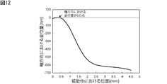
- FIG. 12 is a diagram showing the amount of axial vibration displacement at each position of the vibrating body when the distance between nodes is L-0.5 mm.
- FIG. 8 is an element vector diagram of the vibrating element when the distance between nodes is L + 1 mm.
- FIG. 9 is an element vector diagram of the vibrating element when the distance between nodes is L-0.5 mm.
- FIG. 10 is
- FIG. 13 is a diagram showing the displacement of the vibration in the axial direction at each position of the vibrating body when the distance between the nodes is L + 20 mm.
- FIG. 14 is a diagram for explaining the vibration of the vibration device according to the first modification of the first embodiment of the present invention.
- FIG. 15 is a schematic front sectional view of a vibration device according to a second modification of the first embodiment of the present invention.
- FIG. 16 is a schematic plan view of a vibration device according to a third modification of the first embodiment of the present invention.
- FIG. 17 is a schematic front sectional view of the vibration device according to the second embodiment of the present invention.
- FIG. 18 is a schematic front sectional view of a vibration device according to a modification of the second embodiment of the present invention.
- FIG. 14 is a diagram for explaining the vibration of the vibration device according to the first modification of the first embodiment of the present invention.
- FIG. 15 is a schematic front sectional view of a vibration device according to a second modification of the first embodiment of
- FIG. 19 is a schematic perspective view of a support according to the third embodiment of the present invention.
- FIG. 20 is a schematic perspective view of a support according to the fourth embodiment of the present invention.
- FIG. 21 is a schematic perspective view of a support in a first modified example of the fourth embodiment of the present invention.
- FIG. 22 is a schematic perspective view of a support in a second modified example of the fourth embodiment of the present invention.
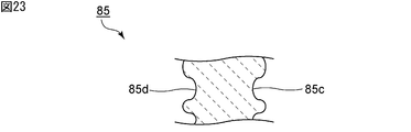
- FIG. 23 is a schematic front sectional view showing a part of the support according to the fifth embodiment of the present invention.
- FIG. 24 is a schematic front sectional view showing a part of the support in the sixth embodiment of the present invention.
- FIG. 1 is a schematic front sectional view of the vibration device according to the first embodiment of the present invention.
- FIG. 2 is a schematic exploded perspective view of the vibration device according to the first embodiment.
- the vibration device 1 shown in FIGS. 1 and 2 is a vibration device that moves water droplets and foreign matter by vibration and removes water droplets and foreign matter from the field of view of the imaging device.
- the vibration device according to the present invention can also be used for applications other than those described above, such as an ultrasonic sensor, a microphone, and a buzzer, for generating sound pressure.
- the vibration device 1 includes the vibration element 2, a support 15 that supports the vibration element 2, and a connection member 14 that connects the vibration element 2 and the support 15. More specifically, the vibration element 2 includes a substantially cylindrical vibration body 3. The vibrating body 3 and the supporting body 15 in the vibrating element 2 are connected by a connecting member 14. In the vibration device 1, an internal space surrounded by the vibration element 2, the connection member 14, and the support 15 is configured.
- FIG. 3 is a front sectional view of an imaging device having the vibration device according to the first embodiment.
- An imaging device 10A indicated by a dashed line is arranged in an internal space surrounded by the vibration element 2, the connection member 14, and the support 15. Thereby, the imaging device 10 as the optical detection device according to the embodiment of the present invention is configured.
- the imaging device 10 has a vibration device 1 and an image sensor 10A.
- the imaging element 10A for example, a CMOS, a CCD, a bolometer, a thermopile, or the like that receives light of any wavelength from the visible region to the far infrared region can be used.
- Examples of the imaging device 10 include a camera, a Radar, and a LIDAR device.
- an optical detection element for optically detecting an energy ray other than the imaging element 10A may be disposed in the internal space.
- the energy ray to be detected may be, for example, an active energy ray such as an electromagnetic wave or an infrared ray.
- the detection area of the optical detection element is included in a light transmitting body 7 described later.
- the field of view of the imaging element 10A is included in the light transmitting body 7.
- the term “light-transmitting property” in the present specification refers to a light-transmitting property that transmits at least an energy ray or light having a wavelength detected by the optical detection element.
- the vibration element 2 includes the vibration body 3, a light transmitting body 7 as a cover, and a piezoelectric vibrator 8.
- the vibrating body 3 has a first open end face 3a and a second open end face 3b, and an outer side face 3c and an inner side face 3d connecting the first open end face 3a and the second open end face 3b.
- the direction connecting the first opening end face 3a and the second opening end face 3b of the vibrating body 3 is defined as an axial direction
- a direction orthogonal to the axial direction is defined as a radial direction.
- the vibrating body 3 has a cylindrical first vibrating body part 4, a cylindrical second vibrating body part 5, and an annular ring connecting the first vibrating body part 4 and the second vibrating body part 5. And a connecting portion 6.
- the vibrating body 3 is a cylindrical body in which the first vibrating body part 4, the connecting part 6, and the second vibrating body part 5 are arranged such that their central axes are at the same position.
- the first vibrating part 4 includes the first opening end face 3 a of the vibrating body 3.
- the second vibrating body section 5 includes the second opening end face 3b of the vibrating body 3. Note that the shapes of the first vibrating body portion 4, the second vibrating body portion 5, and the connecting portion 6 are not limited to the above.
- the first vibrating body part 4, the second vibrating body part 5, and the connecting part 6 may have any shape as long as they are continuously connected so as to form one cylindrical body. Further, the vibrating body 3 is not limited to a configuration having the first vibrating body portion 4, the second vibrating body portion 5, and the connecting portion 6, and may be a cylindrical body. The vibrating body 3 may have, for example, a substantially rectangular cylindrical shape.
- the outer peripheral edge and the inner peripheral edge refer to the outer peripheral edge and the inner peripheral edge in plan view.
- the outer peripheral edges of the connecting portion 6, the first vibrating body portion 4, and the second vibrating body portion 5 overlap.
- the inner peripheral edge of the connecting portion 6 is located outside the inner peripheral edges of the first vibrating body portion 4 and the second vibrating body portion 5.
- the thickness of the connecting portion 6 is smaller than the thickness of the first vibrating body portion 4 and the thickness of the second vibrating body portion 5.
- the inner diameter of the connecting portion 6 is larger than the inner diameters of other portions.
- the outer surface 3c of the vibrating body 3 is formed by connecting the respective outer surfaces of the first vibrating body portion 4, the connecting portion 6, and the second vibrating body portion 5 to each other.
- the inner side surface 3d of the vibrating body 3 is configured by connecting the inner side surfaces of the first vibrating body portion 4, the connecting portion 6, and the second vibrating body portion 5 to each other.
- the inner side surface 3 d has a step at the connecting portion 6.
- the outer surface 3c has no step.
- a light transmitting body 7 is provided on the first opening end face 3 a of the vibrating body 3 so as to cover the opening.
- the light transmitting body 7 is a lid having a light transmitting property.
- the light transmitting body 7 has a dome shape, but the light transmitting body 7 may have a flat plate shape.
- a piezoelectric vibrator 8 is provided on the second opening end face 3 b of the vibrating body 3.
- the portion where the piezoelectric vibrator 8 is provided is not limited to the above.
- the piezoelectric vibrator 8 has an annular piezoelectric body 8a.
- the piezoelectric body 8a is made of, for example, an appropriate piezoelectric ceramic such as Pb (Zr, Ti) O 3 or (K, Na) NbO 3 or an appropriate piezoelectric single crystal such as LiTaO 3 or LiNbO 3 .
- the piezoelectric vibrator 8 has a first electrode 9a provided on one main surface of the piezoelectric body 8a and a second electrode 9b provided on the other main surface.
- the first electrode 9a and the second electrode 9b are annular and provided to face each other.
- the first electrode 9a and the second electrode 9b are each electrically connected to the outside.
- one annular piezoelectric vibrator 8 is provided in the present embodiment, the present invention is not limited to this.
- a plurality of rectangular plate-shaped piezoelectric vibrators 8 may be provided along the outer surface 3c. .
- the piezoelectric vibrator 8 is joined to the vibrating body 3 on the first electrode 9a side.
- the piezoelectric vibrator 8 performs respiratory vibration, causes the vibrating body 3 to perform respiratory vibration, and vibrates a connected body of the vibrating body 3 and the light transmitting body 7.
- the respiratory vibration refers to a vibration mode in which a ring-shaped piezoelectric vibrator or a cylindrical vibrator is displaced in a radial direction.
- the vibration element 2 does not necessarily need to have the piezoelectric vibrator 8, and may have a vibrator that causes the vibrating body 3 to respirate and vibrate.
- connection member 14 is connected to the outer surface 3c of the vibrating body 3. More specifically, the connection member 14 has an outer surface and an inner surface. The inner surface of the connection member 14 is connected to the outer surface 3c of the vibrating body 3. In the vibration device 1, the connection member 14 is provided to extend radially outward from the outer surface 3 c of the vibration body 3. Note that the vibration body 3 and the connection member 14 may be provided integrally. Here, the position of the connection member 14 will be shown more specifically with reference to FIG.
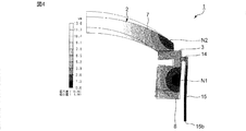
- FIG. 4 is a diagram for explaining the vibration of the vibration device according to the first embodiment and the position of the connection member.
- FIG. 4 shows a portion corresponding to half of the cross section shown in FIG. 1 in the radial direction.
- the vibrating body 3 performs respiratory vibration so that the first node N1 and the second node N2 are generated at different positions in the axial direction of the vibrating element 2. More specifically, in the present embodiment, the first node N1 is located on the vibrating body 3, and the second node N2 is located on the light transmitting body 7.
- the connection member 14 is located between the first node N1 and the second node N2.
- the vibrating body 3 of the present embodiment performs respiratory vibration so as to generate two nodes, but may perform respiratory vibration so as to generate three or more nodes. Also in this case, the first node N1 and the second node N2 are adjacent nodes.
- the support 15 is connected to the outer surface of the connection member 14.
- the support 15 has a connection portion 15a which is a portion connected to the connection member 14.
- the support 15 is connected to the vibrator 3 via the connecting member 14 and supports the vibrator 3.
- the support 15 is a cylindrical body extending in the axial direction.
- the shape of the support 15 is not limited to the above, and may be any shape that extends in the axial direction, such as a rectangular tube.
- the support 15 has an outer surface 15c and an inner surface 15d.
- the connection portion 15a is located near the upper end of the inner surface 15d of the support 15 in FIG. Note that the support 15 and the connection member 14 may be provided integrally.
- the support 15 has a bottom 15b including the lower end in FIG.
- the vibration device 1 is fixed to the outside at the bottom 15 b of the support 15.
- a bottom plate may be joined to the bottom portion 15b, and a closed space may be formed by the vibration element 2, the connection member 14, the support 15, and the bottom plate.
- the feature of this embodiment is that the vibrating body 3 performs respiratory vibration so that the first node and the second node are generated at different positions in the axial direction of the vibrating element 2, and the vibrating body 3 and the supporting body 15 Is located between the first node and the second node.
- This makes it difficult for the vibration to leak to the bottom 15 b of the support 15. Therefore, when the vibration device 1 is fixed to the outside, damping of the vibration of the vibration device 1 hardly occurs. The details will be described below.
- FIG. 5 is an element vector diagram for explaining vibration of the vibration device according to the first embodiment.
- FIG. 5 shows a portion similar to FIG.
- the vibration around the first node N1 and the second node N2 of the vibration element 2 has a rotational moment. Therefore, the vibration of the vibration element 2 has a radial component and an axial component.
- the connection member 14 is located at a portion where the amount of vibration displacement in the axial direction is about 0 ⁇ m. In this specification, unless otherwise specified, the displacement amount is shown as an absolute value.
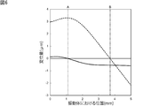
- FIG. 6 is a diagram showing the amount of displacement of the radial and axial vibrations at each position of the vibrating body in the first embodiment.
- the horizontal axis indicates the position in the axial direction of the vibrating body.
- 0 mm on the horizontal axis indicates the position of the first opening end face of the vibrating body.
- the solid line in FIG. 6 indicates the amount of displacement in the axial direction, and the broken line indicates the amount of displacement in the radial direction.
- An alternate long and short dash line A indicates the position where the connecting member is arranged, and an alternate long and short dash line B indicates the position of the first node.
- the displacement of the vibration in the axial direction is about 0 ⁇ m, and the displacement of the vibration in the radial direction is about 3.3 ⁇ m.
- the displacement of the vibration in the radial direction is about 0 ⁇ m, but the displacement of the vibration in the axial direction is about 0.5 ⁇ m.
- a vibrating device having the configuration of the first embodiment and a vibrating device of a comparative example in which the connection member was disposed at the position of the first node were manufactured.
- the displacement amounts of the bottom of the support in the vibration devices of the first embodiment and the comparative example were compared.
- the compared displacement is a displacement obtained by combining the radial component and the axial component.
- the amount of displacement at the bottom of the support was about 2.4 ⁇ m.
- the displacement of the bottom of the support was about 0.2 ⁇ m.
- connection member 14 is located between the first node N1 and the second node N2. Between the first node N1 and the second node N2, both rotational moments about both nodes are combined, so that the amount of displacement in the axial direction is reduced. Thereby, the amount of displacement in the axial direction due to the vibration of the connection member 14 can be effectively reduced. Even if the radial vibration propagates to the support 15 extending in the axial direction, the bottom 15b of the support 15 is not easily displaced. Therefore, it is possible to suppress the vibration of the vibration element 2 from leaking to the bottom 15 b of the support 15. Further, since the displacement of the bottom 15b is very small, when the bottom 15b is fixed to the outside, the damping of the vibration hardly occurs.
- the displacement of the vibration in the axial direction of the portion to which the connection member 14 is connected is preferably 90% or less of the displacement of the vibration in the axial direction of the portion where the first node N1 is located. , 40% or less.
- the displacement amount in the axial direction is 0 ⁇ m.
- FIG. 7 is a diagram showing the relationship between the position of the connection member on the support and the amount of displacement of the bottom of the support.
- the vibration element, the connection member, and the support of the first embodiment are used, and the positions of the connection members are different from each other.
- the horizontal axis indicates the axial position where the connecting member is arranged in the vibrating body. 0 mm on the horizontal axis indicates the position of the first opening end face of the vibrating body.
- the dashed-dotted line A in FIG. 7 indicates the position where the connecting member is arranged in the first embodiment.
- the position shown by the one-dot chain line C is a position where the amount of displacement of the vibrating body in the axial direction is 90% of the amount of displacement of vibration in the axial direction of the portion where the first node is located.
- the position shown by the one-dot chain line D is a position where the amount of displacement of the vibrating body in the axial direction is 40% of the amount of displacement of vibration in the axial direction of the portion where the first node is located.
- the two-dot chain line E indicates the amount of displacement of the bottom of the support when the connecting member is disposed at the first node.
- the two-dot chain line F indicates the amount of displacement of the bottom of the support when the connecting member is arranged at the position indicated by the one-dot chain line D.
- the amount of displacement of the vibration in the axial direction between the first node N1 and the second node N2 is small. Further, a portion where the amount of vibration displacement is 0 is located between the first node N1 and the second node N2. The fact that they do not depend on the distance between the first node N1 and the second node N2 will be described below. In this specification, unless otherwise specified, the distance between nodes refers to the distance between the first node N1 and the second node N2.
- a plurality of vibrating elements having different distances between the nodes from those of the first embodiment were manufactured. More specifically, assuming that the distance between the nodes in the first embodiment is L, the vibrating elements having the above distances of L + 1 mm, L-0.5 mm, and L + 20 mm were manufactured. The distance between the nodes was changed by changing the length of the connecting portion of the vibrating body along the axial direction. Next, the displacement of vibration of each vibration element was measured.
- FIG. 8 is an element vector diagram of the vibrating element when the distance between nodes is L + 1 mm.
- FIG. 9 is an element vector diagram of the vibrating element when the distance between nodes is L-0.5 mm.
- FIG. 10 is an element vector diagram of the vibrating element when the distance between nodes is L + 20 mm.
- the first node N1 is located on the vibrating body 3 and the second node N2 is located on the light transmitting body 7 even when the distance between the nodes is varied. It can be seen that the displacement of the vibration in the light transmitting body 7 is larger than the displacement of the vibration between the first opening end face 3a of the vibrating body 3 and the first node N1, regardless of the distance between the nodes. This is because the amount of displacement when the light transmitting member is excited in the resonance region is represented by the product of the amount of displacement of the vibrating member and Qm of the light transmitting member.
- Qm is the reciprocal of the elastic loss coefficient.
- the displacement of the vibration generated in the piezoelectric vibrator is amplified by Qm times the vibrator.
- the vibration generated in the piezoelectric vibrator propagates to the light transmitting body via the vibrating body and the light transmitting body vibrates at the resonance frequency
- the displacement of the vibration generated in the piezoelectric vibrator is further amplified by Qm times the light transmitting body. Is done.
- FIG. 11 is a diagram showing the amount of axial vibration displacement at each position of the vibrating body when the distance between nodes is L + 1 mm.
- FIG. 12 is a diagram showing the amount of axial vibration displacement at each position of the vibrating body when the distance between nodes is L-0.5 mm.
- FIG. 13 is a diagram showing the displacement of the vibration in the axial direction at each position of the vibrating body when the distance between the nodes is L + 20 mm. 11 to 13, 0 mm on the horizontal axis indicates the position of the first opening end face of the vibrating body.
- the distance between the first node N1 and the second node N2 is It can be seen that a portion where the displacement of the vibration in the axial direction is 0 is located. Further, it can be seen that the amount of displacement in the axial direction between the first node N1 and the second node N2 is small. As described above, regardless of the distance between the nodes, the portion where the amount of vibration displacement in the axial direction becomes 0 is located between the first node N1 and the second node N2, and the first opening end surface 3a It can be seen that the amount of displacement in the axial direction becomes smaller between the first node N1 and the first node N1.
- the displacement amount of the light transmitting member 7 where the second node N2 is located is smaller than the displacement amount of the vibration between the first opening end face 3a of the vibrating member 3 and the first node N1. Is also big. Therefore, it is understood that the amount of displacement in the axial direction between the first node N1 and the second node N2 becomes small regardless of the distance between the nodes.
- the material of the support 15 is preferably a material having a spring property such as a metal material.
- the support 15 is easily deformed.
- the vibration of the vibration element 2 propagates to the support 15 via the connection member 14, the vicinity of the connection portion 15a of the support 15 is easily deformed. Therefore, the displacement of the entire support 15 can be suppressed, and the displacement of the bottom 15b of the support 15 can be suppressed. Therefore, it is possible to effectively suppress the leakage of the vibration to the bottom portion 15b, and it is also possible to effectively suppress the damping of the vibration.
- the material of the support 15 is a metal material
- the rigidity can be increased, and in addition to the above-described effects, the support 15 is not easily damaged.
- the vibrating body 3 is made of a metal material, it is preferable that an insulating film is provided between the piezoelectric vibrator 8 and the vibrating body 3.
- the vibrating body 3, the connecting member 14, and the supporting body 15 are made of the same material. In this case, the reflection of vibration and the like can be suppressed, and the vibration of the vibration device 1 is hardly attenuated. More preferably, the vibrating body 3, the connecting member 14, and the support 15 are made of a metal material. Thereby, as described above, vibration leakage and damping can be effectively suppressed. Note that the vibrator 3, the connection member 14, and the support 15 may be made of a ceramic material or the like.
- both the first node N1 and the second node N2 are located on the vibrating body 3, and the connecting member 14 is connected to the first node N1 and the second node N1. It is located between N2.
- a disc-shaped lid 27 having no translucency is provided on the first opening end face 3a of the vibrating body 3.
- the lid 27 is made of, for example, a metal material or a ceramic material.
- the vibration device of this modification can be used for applications such as an ultrasonic sensor, a microphone, a buzzer, and the like that generate sound pressure.
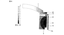
- the vibrating body 3 and the support 15 are connected by a plurality of connecting members 24 arranged in a circumferential direction with the axial direction as the rotation axis.
- the connecting members 24 are indicated by hatching.
- Each connecting member 24 has an annular arc shape.
- the plurality of connection members 24 are located between the first node N1 and the second node N2.
- FIG. 17 is a schematic front sectional view of the vibration device according to the second embodiment.
- the present embodiment is different from the first embodiment in that the bottom 35b of the support 35 is thicker than the other portions. More specifically, the thickness of the support 35 is the same except for the bottom 35b.
- the bottom 35b extends radially outward, and a cross section of the support 35 along the axial direction has a substantially L-shape. Except for the above points, the vibration device of the present embodiment has the same configuration as the vibration device 1 of the first embodiment.
- the portion located closer to the connection portion 15a than the bottom portion 35b is more easily deformed than the bottom portion 35b. Accordingly, when the vibration of the vibration element 2 propagates to the support 35 via the connection member 14, the portion on the connection portion 15a side can be more easily deformed than the bottom portion 35b. Therefore, it is possible to further suppress that the entire support 35 is integrally displaced. In addition, since the bottom 35b is thick, displacement of the bottom 35b can be further suppressed. Therefore, the leakage of the vibration to the bottom 35b can be further suppressed, and the damping of the vibration can be further suppressed.
- the direction in which the bottom 35b of the support 35 extends is not limited to the radial outside.
- the bottom 45b of the support 45 extends radially inward, and the cross section of the support 45 along the axial direction has a substantially L-shape. Also in this case, leakage and damping of vibration can be further suppressed. In addition, the size of the vibration device can be reduced.
- FIG. 19 is a schematic perspective view of a support according to the third embodiment.
- the present embodiment is different from the first embodiment in that the support 55 has a substantially rectangular cylindrical shape and the outer surface 55c is inclined with respect to the axial direction. Except for the above points, the vibration device of the present embodiment has the same configuration as the vibration device 1 of the first embodiment.
- the shape of the outer peripheral edge of the support 55 in a plan view is a square.
- the outer surface 55c of the support 55 has a shape in which four trapezoidal surfaces are connected.
- the inner side surface 55d has a columnar shape as in the first embodiment.
- the outer surface 55c of the support 55 is inclined with respect to the axial direction so that the thickness decreases from the bottom portion 55b toward the connection portion 15a. Accordingly, a portion located closer to the connection portion 15a than the bottom portion 55b is more easily deformed than the bottom portion 55b.
- the shape of the outer peripheral edge of the support 55 in a plan view may be, for example, a polygon other than a square, a substantially polygon, or a circle or a substantially circle.
- the outer surface 55c of the support 55 is inclined with respect to the axial direction.
- the outer surface 55c has a stepped shape, so that the thickness increases from the bottom 55b toward the connecting portion 15a. It may be thin. Also in this case, it is possible to suppress vibration leakage and damping.
- FIG. 20 is a schematic perspective view of a support according to the fourth embodiment.
- the present embodiment is different from the first embodiment in the shape of the support 65. Except for the above points, the vibration device of the present embodiment has the same configuration as the vibration device 1 of the first embodiment.
- the support 65 has a frame-shaped bottom 65b whose inner and outer peripheral edges are square.
- One end of a pillar 65e is connected to each corner of the bottom 65b.
- the column 65e extends in the axial direction.
- the thickness of the pillar 65e of the support 65 is constant and the same as the thickness of the bottom 65b.
- the other end of each column 65e is connected to the frame 65f.
- the outer peripheral edge of the frame portion 65f is square, and the inner peripheral edge is circular.
- Each pillar 65e is connected to each corner of the frame 65f.
- the inner peripheral edge of the frame portion 65f is a connecting portion 15a connected to the connecting member 14.
- the column 65e is more easily deformed in the direction orthogonal to the axial direction than the frame-shaped bottom 65b.
- the shape of the outer periphery of the bottom portion 65b and the frame portion 65f in a plan view may be, for example, a polygon other than a square, a substantially polygon, or a circle or a substantially circle.
- the thickness of the pillar 65e of the support 65 and the thickness of the bottom 65b may not be the same.
- the thickness of the bottom 75b is larger than the thickness of the column 65e. Thereby, the displacement of the bottom portion 75b can be further suppressed. Therefore, the leakage of the vibration to the bottom portion 75b can be further suppressed, and the damping of the vibration can be further suppressed.
- the bottom 75b extends outward in the direction orthogonal to the axial direction, but the bottom 75b may extend inward in the direction orthogonal to the axial direction.
- the thickness of the pillar portion 65e is constant, but is not limited to this.
- the cross section along the axial direction of the column 76e of the support 76 has a substantially right triangle shape.
- the thickness of the column portion 76e decreases from the bottom portion 76b toward the connection portion 15a.
- a portion located closer to the connection portion 15a than the bottom portion 76b is more easily deformed than the bottom portion 76b.
- FIG. 23 is a schematic front sectional view showing a part of the support in the fifth embodiment.
- This embodiment is different from the first embodiment in that the outer surface 85c and the inner surface 85d of the support 85 have a wavy shape. Except for the above points, the vibration device of the present embodiment has the same configuration as the vibration device 1 of the first embodiment.
- the outer surface 85c and the inner surface 85d of the support 85 are curved and have a wavy shape. More specifically, the outer surface 85c is wavy such that the outer diameter repeatedly increases from the bottom toward the connection and then decreases from the bottom toward the connection.
- the inner side surface 85d is wavy such that the inner diameter repeatedly increases from the bottom toward the connection portion and then decreases from the bottom toward the connection portion.
- the support 85 has such a shape that the thickness of the support 85 repeats such that the thickness increases from the bottom toward the connection, and then the thickness decreases from the bottom toward the connection.
- the outer surface 85c and the inner surface 85d of the support 85 have a wavy shape, the spring property of the portion of the support 85 closer to the connection portion than the bottom portion can be improved. Thereby, the displacement of the entire support 85 can be suppressed, and the displacement of the bottom of the support 85 can be suppressed. Therefore, leakage of vibration to the bottom can be effectively suppressed, and damping of vibration can also be effectively suppressed.
- a point where the outer diameter of the support 85 increases from the bottom toward the connection portion and then begins to decrease is referred to as a mountain portion.
- the point at which the outer diameter decreases from the bottom toward the connection and then begins to increase is defined as a valley.
- a point where the inner diameter of the support 85 decreases from the bottom toward the connection and then starts to increase is defined as a mountain portion.
- the point at which the inner diameter increases from the bottom toward the connection and then begins to decrease is defined as a valley.
- the crest portion of the outer side surface 85c and the crest portion of the inner side surface 85d are the same in the axial direction.
- the valley portion of the outer surface 85c and the valley portion of the inner surface 85d are preferably the same in the axial direction.
- the cross-sectional shape of the support 85 along the axial direction is line-symmetric with respect to the axis of symmetry extending in the axial direction. Thereby, the spring property can be effectively improved.
- the outer surface 85c and the inner surface 85d of the support 85 may be linear and have a wavy shape. Also in this case, the spring property can be enhanced, and leakage and damping of vibration can be suppressed.
- FIG. 24 is a schematic front sectional view showing a part of the support in the sixth embodiment.
- This embodiment is different from the second embodiment in that both the outer surface 95c and the inner surface 95d of the support 95 have a stepped shape. Except for the above points, the vibration device of the present embodiment has the same configuration as the vibration device of the second embodiment.
- the support 95 is bent stepwise at a plurality of portions. More specifically, in the support body 95, portions extending in the axial direction and portions extending in the radial direction are connected alternately. Thereby, the spring property of the support 95 can be enhanced. Therefore, as in the fifth embodiment, leakage and damping of vibration can be suppressed.
- the thickness of the bottom portion 95b is greater than the thickness of the portion extending in the axial direction. Therefore, similarly to the second embodiment, the displacement of the bottom portion 95b can be further suppressed. Therefore, the leakage of the vibration to the bottom 95b can be further suppressed, and the damping of the vibration can be further suppressed.
- Second vibration body part 6 Connecting part 7 Translucent member 8 Piezoelectric vibrator 8a Piezoelectric member 9a First electrode 9b Second electrode 10 Imaging device 10A Imaging element 14 Connection member 15 Support member 15a Connection part 15b Bottom 15c Outside surface 15d Inner surface 24 Connection member 27 Lid 35 Support 35b Bottom 45 Support 45b Bottom 55 Support 55b Bottom 55c Outside surface 55d Inner surface 65 Support 65b Bottom 65e Column 65f Frame 75 Support 75b Bottom 76 Support 76b Bottom 76e Column 85 Support 85c Outer surface 85d Inner surface 95 Support 95b Bottom 95c: Outside surface 95d: Inside surface
Landscapes
- Physics & Mathematics (AREA)
- General Physics & Mathematics (AREA)
- Engineering & Computer Science (AREA)
- Mechanical Engineering (AREA)
- Multimedia (AREA)
- Signal Processing (AREA)
- Apparatuses For Generation Of Mechanical Vibrations (AREA)
- Piezo-Electric Or Mechanical Vibrators, Or Delay Or Filter Circuits (AREA)
- Measurement Of Mechanical Vibrations Or Ultrasonic Waves (AREA)
Abstract
L'invention concerne un dispositif de vibration qui peut supprimer la fuite et l'amortissement de vibrations. Ce dispositif de vibration 1 est pourvu : d'un élément de vibration 2 qui comprend un vibreur cylindrique 3 comprenant une première face d'extrémité ouverte 3a et une seconde face d'extrémité ouverte 3b ; d'un support 15, qui, lorsque la direction axiale est définie comme étant une direction reliant la première face d'extrémité ouverte 3a et la seconde face d'extrémité ouverte 3b du vibreur 3, s'étend dans la direction axiale et supporte le vibreur 3 ; et d'un élément de liaison 14 qui relie le vibreur 3 au support 15. Le vibreur 3 effectue une vibration de respiration de façon à générer un premier noeud et un second noeud à différentes positions dans la direction axiale de l'élément de vibration 2 et l'élément de liaison 14 est positionné entre le premier noeud et le second noeud.
Priority Applications (4)
| Application Number | Priority Date | Filing Date | Title |
|---|---|---|---|
| EP19867596.9A EP3838426A4 (fr) | 2018-09-28 | 2019-04-12 | Dispositif de vibration et appareil de détection optique |
| JP2020547935A JP7010386B2 (ja) | 2018-09-28 | 2019-04-12 | 振動装置及び光学検出装置 |
| CN201980060645.5A CN112703063B (zh) | 2018-09-28 | 2019-04-12 | 振动装置和光学检测装置 |
| US17/108,031 US11980914B2 (en) | 2018-09-28 | 2020-12-01 | Vibrating device and optical detection apparatus |
Applications Claiming Priority (2)
| Application Number | Priority Date | Filing Date | Title |
|---|---|---|---|
| JP2018-183412 | 2018-09-28 | ||
| JP2018183412 | 2018-09-28 |
Related Child Applications (1)
| Application Number | Title | Priority Date | Filing Date |
|---|---|---|---|
| US17/108,031 Continuation US11980914B2 (en) | 2018-09-28 | 2020-12-01 | Vibrating device and optical detection apparatus |
Publications (1)
| Publication Number | Publication Date |
|---|---|
| WO2020066088A1 true WO2020066088A1 (fr) | 2020-04-02 |
Family
ID=69951320
Family Applications (1)
| Application Number | Title | Priority Date | Filing Date |
|---|---|---|---|
| PCT/JP2019/015980 WO2020066088A1 (fr) | 2018-09-28 | 2019-04-12 | Dispositif de vibration et appareil de détection optique |
Country Status (5)
| Country | Link |
|---|---|
| US (1) | US11980914B2 (fr) |
| EP (1) | EP3838426A4 (fr) |
| JP (1) | JP7010386B2 (fr) |
| CN (1) | CN112703063B (fr) |
| WO (1) | WO2020066088A1 (fr) |
Cited By (1)
| Publication number | Priority date | Publication date | Assignee | Title |
|---|---|---|---|---|
| WO2021192387A1 (fr) * | 2020-03-27 | 2021-09-30 | 株式会社村田製作所 | Dispositif vibration et procédé de commande de vibration |
Citations (3)
| Publication number | Priority date | Publication date | Assignee | Title |
|---|---|---|---|---|
| JPS62254667A (ja) | 1986-04-28 | 1987-11-06 | Murata Mfg Co Ltd | 円筒型圧電振動子の支持構造 |
| JP2017170303A (ja) * | 2016-03-22 | 2017-09-28 | オリンパス株式会社 | 液滴排除装置と、液滴排除装置を有する画像装置及び上記液滴排除装置の制御方法と上記液滴排除装置の制御プログラム |
| WO2018100796A1 (fr) * | 2016-11-30 | 2018-06-07 | 株式会社村田製作所 | Dispositif de vibration, dispositif d'élimination de gouttelettes d'eau destiné à une caméra, et caméra |
Family Cites Families (20)
| Publication number | Priority date | Publication date | Assignee | Title |
|---|---|---|---|---|
| JP4082982B2 (ja) * | 2002-10-24 | 2008-04-30 | 株式会社アサヒ・イー・エム・エス | 超音波撓み振動体の支持方法 |
| US7224104B2 (en) * | 2003-12-09 | 2007-05-29 | Kabushiki Kaisha Toshiba | Ultrasonic probe and ultrasonic diagnostic apparatus |
| JP4871802B2 (ja) * | 2007-07-09 | 2012-02-08 | キヤノン株式会社 | 駆動装置および撮像装置 |
| JP6071285B2 (ja) * | 2012-07-06 | 2017-02-01 | キヤノン株式会社 | 静電容量型トランスデューサ |
| US10419653B2 (en) * | 2015-06-19 | 2019-09-17 | Canon Kabushiki Kaisha | Vibration drive device capable of generating click feeling and image pickup apparatus |
| WO2017022382A1 (fr) * | 2015-08-04 | 2017-02-09 | 株式会社村田製作所 | Dispositif vibrant et caméra |
| WO2017110563A1 (fr) * | 2015-12-24 | 2017-06-29 | 株式会社村田製作所 | Dispositif de vibration, procédé pour piloter ce dernier et caméra |
| JP6579200B2 (ja) * | 2015-12-25 | 2019-09-25 | 株式会社村田製作所 | 振動装置及びカメラ |
| CN108474998B (zh) | 2016-03-03 | 2020-10-30 | 株式会社村田制作所 | 振动装置及其驱动方法、以及摄像头 |
| WO2018003985A1 (fr) * | 2016-06-30 | 2018-01-04 | 株式会社ニコン | Moteur à ondes vibratoires et dispositif optique |
| WO2018100795A1 (fr) * | 2016-11-30 | 2018-06-07 | 株式会社村田製作所 | Dispositif de vibration, dispositif d'élimination de goutte d'eau pour caméras, et caméra |
| CN110546941B (zh) * | 2017-04-24 | 2022-03-04 | 株式会社村田制作所 | 清洗装置和具备清洗装置的摄像单元 |
| CN110574358B (zh) * | 2017-04-26 | 2021-05-28 | 株式会社村田制作所 | 清洗装置以及具备清洗装置的摄像单元 |
| JP6977784B2 (ja) * | 2017-12-27 | 2021-12-08 | 株式会社村田製作所 | 振動装置及び光学検出装置 |
| JP6943341B2 (ja) * | 2018-06-28 | 2021-09-29 | 株式会社村田製作所 | 振動装置及び光学検出装置 |
| JP7070497B2 (ja) * | 2019-04-25 | 2022-05-18 | 株式会社村田製作所 | 振動装置及び光学検出装置 |
| EP3971639A4 (fr) * | 2019-05-16 | 2023-06-28 | Murata Manufacturing Co., Ltd. | Dispositif optique et unité optique comprenant un dispositif optique |
| JP6819846B1 (ja) * | 2019-11-22 | 2021-01-27 | 株式会社村田製作所 | 振動装置、および振動装置を備える撮像ユニット |
| EP3852354B1 (fr) * | 2019-11-22 | 2023-10-25 | Murata Manufacturing Co., Ltd. | Dispositif de vibration, et unité d'imagerie comprenant ce dispositif de vibration |
| WO2021192387A1 (fr) * | 2020-03-27 | 2021-09-30 | 株式会社村田製作所 | Dispositif vibration et procédé de commande de vibration |
-
2019
- 2019-04-12 WO PCT/JP2019/015980 patent/WO2020066088A1/fr unknown
- 2019-04-12 JP JP2020547935A patent/JP7010386B2/ja active Active
- 2019-04-12 CN CN201980060645.5A patent/CN112703063B/zh active Active
- 2019-04-12 EP EP19867596.9A patent/EP3838426A4/fr active Pending
-
2020
- 2020-12-01 US US17/108,031 patent/US11980914B2/en active Active
Patent Citations (3)
| Publication number | Priority date | Publication date | Assignee | Title |
|---|---|---|---|---|
| JPS62254667A (ja) | 1986-04-28 | 1987-11-06 | Murata Mfg Co Ltd | 円筒型圧電振動子の支持構造 |
| JP2017170303A (ja) * | 2016-03-22 | 2017-09-28 | オリンパス株式会社 | 液滴排除装置と、液滴排除装置を有する画像装置及び上記液滴排除装置の制御方法と上記液滴排除装置の制御プログラム |
| WO2018100796A1 (fr) * | 2016-11-30 | 2018-06-07 | 株式会社村田製作所 | Dispositif de vibration, dispositif d'élimination de gouttelettes d'eau destiné à une caméra, et caméra |
Non-Patent Citations (1)
| Title |
|---|
| See also references of EP3838426A4 |
Cited By (3)
| Publication number | Priority date | Publication date | Assignee | Title |
|---|---|---|---|---|
| WO2021192387A1 (fr) * | 2020-03-27 | 2021-09-30 | 株式会社村田製作所 | Dispositif vibration et procédé de commande de vibration |
| US20210302723A1 (en) * | 2020-03-27 | 2021-09-30 | Murata Manufacturing Co., Ltd. | Vibration device and vibration control method |
| US11754830B2 (en) | 2020-03-27 | 2023-09-12 | Murata Manufacturing Co., Ltd. | Vibration device and vibration control method |
Also Published As
| Publication number | Publication date |
|---|---|
| US20210078043A1 (en) | 2021-03-18 |
| CN112703063A (zh) | 2021-04-23 |
| JP7010386B2 (ja) | 2022-01-26 |
| EP3838426A4 (fr) | 2022-06-22 |
| US11980914B2 (en) | 2024-05-14 |
| EP3838426A1 (fr) | 2021-06-23 |
| JPWO2020066088A1 (ja) | 2021-04-01 |
| CN112703063B (zh) | 2022-04-19 |
Similar Documents
| Publication | Publication Date | Title |
|---|---|---|
| JP6977785B2 (ja) | 振動装置及び光学検出装置 | |
| EP3623059B1 (fr) | Dispositif de vibration | |
| WO2017221622A1 (fr) | Dispositif vibrant et dispositif de capture d'image | |
| WO2012131825A1 (fr) | Oscillateur et dispositif électronique | |
| WO2021038942A1 (fr) | Dispositif de vibration et dispositif de détection optique | |
| JPWO2020003573A1 (ja) | 振動装置及び光学検出装置 | |
| WO2020003572A1 (fr) | Dispositif de vibration et dispositif de détection optique | |
| JP6962470B2 (ja) | 振動装置 | |
| WO2020066088A1 (fr) | Dispositif de vibration et appareil de détection optique | |
| JP2010122412A (ja) | 光学反射素子ユニット | |
| US9097894B2 (en) | Optical deflector including four coupling bars between support body and frame | |
| JP5434668B2 (ja) | 光走査装置 | |
| JP2015103821A (ja) | 静電容量型トランスデューサ及びその作製方法 | |
| JP5298985B2 (ja) | 光走査装置 | |
| WO2019225042A1 (fr) | Dispositif d'oscillation et dispositif de détection optique | |
| WO2020137262A1 (fr) | Dispositif de vibration et dispositif de détection optique | |
| JP6263902B2 (ja) | 超音波発生装置 | |
| JP6983732B2 (ja) | 圧電アクチュエータ | |
| WO2023100396A1 (fr) | Module optique et dispositif optique | |
| ES2251457T3 (es) | Proyector de frecuencia de resonancia sintonizable. | |
| JPWO2015136830A1 (ja) | 光学デバイスおよびその製造方法 |
Legal Events
| Date | Code | Title | Description |
|---|---|---|---|
| 121 | Ep: the epo has been informed by wipo that ep was designated in this application |
Ref document number: 19867596 Country of ref document: EP Kind code of ref document: A1 |
|
| ENP | Entry into the national phase |
Ref document number: 2020547935 Country of ref document: JP Kind code of ref document: A |
|
| NENP | Non-entry into the national phase |
Ref country code: DE |
|
| ENP | Entry into the national phase |
Ref document number: 2019867596 Country of ref document: EP Effective date: 20210428 |