WO2017022382A1 - Dispositif vibrant et caméra - Google Patents
Dispositif vibrant et caméra Download PDFInfo
- Publication number
- WO2017022382A1 WO2017022382A1 PCT/JP2016/069399 JP2016069399W WO2017022382A1 WO 2017022382 A1 WO2017022382 A1 WO 2017022382A1 JP 2016069399 W JP2016069399 W JP 2016069399W WO 2017022382 A1 WO2017022382 A1 WO 2017022382A1
- Authority
- WO
- WIPO (PCT)
- Prior art keywords
- cylindrical
- vibration
- body portion
- mode
- vibration device
- Prior art date
Links
- 230000008878 coupling Effects 0.000 claims abstract description 108
- 238000010168 coupling process Methods 0.000 claims abstract description 108
- 238000005859 coupling reaction Methods 0.000 claims abstract description 108
- 238000006243 chemical reaction Methods 0.000 claims description 109
- 230000000694 effects Effects 0.000 claims description 24
- 238000005452 bending Methods 0.000 claims description 10
- 230000029058 respiratory gaseous exchange Effects 0.000 claims description 8
- 230000000241 respiratory effect Effects 0.000 claims description 6
- XLYOFNOQVPJJNP-UHFFFAOYSA-N water Substances O XLYOFNOQVPJJNP-UHFFFAOYSA-N 0.000 abstract description 39
- 238000006073 displacement reaction Methods 0.000 description 40
- 230000004048 modification Effects 0.000 description 16
- 238000012986 modification Methods 0.000 description 16
- 229910052751 metal Inorganic materials 0.000 description 13
- 239000002184 metal Substances 0.000 description 13
- 239000012535 impurity Substances 0.000 description 9
- 239000000919 ceramic Substances 0.000 description 8
- 238000010586 diagram Methods 0.000 description 7
- 239000000243 solution Substances 0.000 description 7
- LFQSCWFLJHTTHZ-UHFFFAOYSA-N Ethanol Chemical compound CCO LFQSCWFLJHTTHZ-UHFFFAOYSA-N 0.000 description 6
- 238000002474 experimental method Methods 0.000 description 5
- 150000003839 salts Chemical class 0.000 description 5
- FAPWRFPIFSIZLT-UHFFFAOYSA-M Sodium chloride Chemical compound [Na+].[Cl-] FAPWRFPIFSIZLT-UHFFFAOYSA-M 0.000 description 4
- 239000007864 aqueous solution Substances 0.000 description 4
- 239000011521 glass Substances 0.000 description 4
- 238000003384 imaging method Methods 0.000 description 4
- 230000002093 peripheral effect Effects 0.000 description 4
- 230000005684 electric field Effects 0.000 description 3
- 239000007788 liquid Substances 0.000 description 3
- 239000000463 material Substances 0.000 description 3
- 230000010287 polarization Effects 0.000 description 3
- UXVMQQNJUSDDNG-UHFFFAOYSA-L Calcium chloride Chemical compound [Cl-].[Cl-].[Ca+2] UXVMQQNJUSDDNG-UHFFFAOYSA-L 0.000 description 2
- 229910000737 Duralumin Inorganic materials 0.000 description 2
- 239000001110 calcium chloride Substances 0.000 description 2
- 229910001628 calcium chloride Inorganic materials 0.000 description 2
- 239000003795 chemical substances by application Substances 0.000 description 2
- 239000004020 conductor Substances 0.000 description 2
- 238000007710 freezing Methods 0.000 description 2
- 229910000833 kovar Inorganic materials 0.000 description 2
- 239000012528 membrane Substances 0.000 description 2
- 239000002245 particle Substances 0.000 description 2
- 229920003023 plastic Polymers 0.000 description 2
- 239000004065 semiconductor Substances 0.000 description 2
- 238000004088 simulation Methods 0.000 description 2
- 239000011780 sodium chloride Substances 0.000 description 2
- 229910001220 stainless steel Inorganic materials 0.000 description 2
- 239000010935 stainless steel Substances 0.000 description 2
- 229920003002 synthetic resin Polymers 0.000 description 2
- 239000000057 synthetic resin Substances 0.000 description 2
- 230000000007 visual effect Effects 0.000 description 2
- 229910003322 NiCu Inorganic materials 0.000 description 1
- 239000000853 adhesive Substances 0.000 description 1
- 230000001070 adhesive effect Effects 0.000 description 1
- 239000012790 adhesive layer Substances 0.000 description 1
- 229910045601 alloy Inorganic materials 0.000 description 1
- 239000000956 alloy Substances 0.000 description 1
- 229910052782 aluminium Inorganic materials 0.000 description 1
- 230000005540 biological transmission Effects 0.000 description 1
- 238000005219 brazing Methods 0.000 description 1
- VNNRSPGTAMTISX-UHFFFAOYSA-N chromium nickel Chemical compound [Cr].[Ni] VNNRSPGTAMTISX-UHFFFAOYSA-N 0.000 description 1
- 239000011247 coating layer Substances 0.000 description 1
- 239000000084 colloidal system Substances 0.000 description 1
- 229910052802 copper Inorganic materials 0.000 description 1
- 239000013078 crystal Substances 0.000 description 1
- 238000002425 crystallisation Methods 0.000 description 1
- 230000008025 crystallization Effects 0.000 description 1
- 230000007423 decrease Effects 0.000 description 1
- 230000008020 evaporation Effects 0.000 description 1
- 238000001704 evaporation Methods 0.000 description 1
- 239000011796 hollow space material Substances 0.000 description 1
- 230000002209 hydrophobic effect Effects 0.000 description 1
- 230000001771 impaired effect Effects 0.000 description 1
- HFGPZNIAWCZYJU-UHFFFAOYSA-N lead zirconate titanate Chemical compound [O-2].[O-2].[O-2].[O-2].[O-2].[Ti+4].[Zr+4].[Pb+2] HFGPZNIAWCZYJU-UHFFFAOYSA-N 0.000 description 1
- 229910052451 lead zirconate titanate Inorganic materials 0.000 description 1
- 239000006166 lysate Substances 0.000 description 1
- 230000007257 malfunction Effects 0.000 description 1
- 229910001120 nichrome Inorganic materials 0.000 description 1
- 230000003287 optical effect Effects 0.000 description 1
- 238000001556 precipitation Methods 0.000 description 1
- 229910052709 silver Inorganic materials 0.000 description 1
- 239000002689 soil Substances 0.000 description 1
- 239000005341 toughened glass Substances 0.000 description 1
Images


Classifications
-
- G—PHYSICS
- G02—OPTICS
- G02B—OPTICAL ELEMENTS, SYSTEMS OR APPARATUS
- G02B27/00—Optical systems or apparatus not provided for by any of the groups G02B1/00 - G02B26/00, G02B30/00
- G02B27/0006—Optical systems or apparatus not provided for by any of the groups G02B1/00 - G02B26/00, G02B30/00 with means to keep optical surfaces clean, e.g. by preventing or removing dirt, stains, contamination, condensation
-
- B—PERFORMING OPERATIONS; TRANSPORTING
- B06—GENERATING OR TRANSMITTING MECHANICAL VIBRATIONS IN GENERAL
- B06B—METHODS OR APPARATUS FOR GENERATING OR TRANSMITTING MECHANICAL VIBRATIONS OF INFRASONIC, SONIC, OR ULTRASONIC FREQUENCY, e.g. FOR PERFORMING MECHANICAL WORK IN GENERAL
- B06B3/00—Methods or apparatus specially adapted for transmitting mechanical vibrations of infrasonic, sonic, or ultrasonic frequency
- B06B3/02—Methods or apparatus specially adapted for transmitting mechanical vibrations of infrasonic, sonic, or ultrasonic frequency involving a change of amplitude
-
- G—PHYSICS
- G03—PHOTOGRAPHY; CINEMATOGRAPHY; ANALOGOUS TECHNIQUES USING WAVES OTHER THAN OPTICAL WAVES; ELECTROGRAPHY; HOLOGRAPHY
- G03B—APPARATUS OR ARRANGEMENTS FOR TAKING PHOTOGRAPHS OR FOR PROJECTING OR VIEWING THEM; APPARATUS OR ARRANGEMENTS EMPLOYING ANALOGOUS TECHNIQUES USING WAVES OTHER THAN OPTICAL WAVES; ACCESSORIES THEREFOR
- G03B17/00—Details of cameras or camera bodies; Accessories therefor
- G03B17/02—Bodies
-
- G—PHYSICS
- G03—PHOTOGRAPHY; CINEMATOGRAPHY; ANALOGOUS TECHNIQUES USING WAVES OTHER THAN OPTICAL WAVES; ELECTROGRAPHY; HOLOGRAPHY
- G03B—APPARATUS OR ARRANGEMENTS FOR TAKING PHOTOGRAPHS OR FOR PROJECTING OR VIEWING THEM; APPARATUS OR ARRANGEMENTS EMPLOYING ANALOGOUS TECHNIQUES USING WAVES OTHER THAN OPTICAL WAVES; ACCESSORIES THEREFOR
- G03B17/00—Details of cameras or camera bodies; Accessories therefor
- G03B17/56—Accessories
-
- B—PERFORMING OPERATIONS; TRANSPORTING
- B06—GENERATING OR TRANSMITTING MECHANICAL VIBRATIONS IN GENERAL
- B06B—METHODS OR APPARATUS FOR GENERATING OR TRANSMITTING MECHANICAL VIBRATIONS OF INFRASONIC, SONIC, OR ULTRASONIC FREQUENCY, e.g. FOR PERFORMING MECHANICAL WORK IN GENERAL
- B06B1/00—Methods or apparatus for generating mechanical vibrations of infrasonic, sonic, or ultrasonic frequency
- B06B1/02—Methods or apparatus for generating mechanical vibrations of infrasonic, sonic, or ultrasonic frequency making use of electrical energy
- B06B1/06—Methods or apparatus for generating mechanical vibrations of infrasonic, sonic, or ultrasonic frequency making use of electrical energy operating with piezoelectric effect or with electrostriction
-
- G—PHYSICS
- G03—PHOTOGRAPHY; CINEMATOGRAPHY; ANALOGOUS TECHNIQUES USING WAVES OTHER THAN OPTICAL WAVES; ELECTROGRAPHY; HOLOGRAPHY
- G03B—APPARATUS OR ARRANGEMENTS FOR TAKING PHOTOGRAPHS OR FOR PROJECTING OR VIEWING THEM; APPARATUS OR ARRANGEMENTS EMPLOYING ANALOGOUS TECHNIQUES USING WAVES OTHER THAN OPTICAL WAVES; ACCESSORIES THEREFOR
- G03B17/00—Details of cameras or camera bodies; Accessories therefor
- G03B17/02—Bodies
- G03B17/08—Waterproof bodies or housings
-
- H—ELECTRICITY
- H04—ELECTRIC COMMUNICATION TECHNIQUE
- H04N—PICTORIAL COMMUNICATION, e.g. TELEVISION
- H04N23/00—Cameras or camera modules comprising electronic image sensors; Control thereof
- H04N23/50—Constructional details
- H04N23/51—Housings
Definitions
- the present invention relates to a vibration device used for a camera body having a lens, and a camera.
- Patent Document 1 discloses a dome-type cover used for such applications.
- a cylindrical portion is connected to the dome-type cover, and a piezoelectric ceramic vibrator is attached to the cylindrical portion.
- a piezoelectric ceramic vibrator By vibrating the piezoelectric ceramic vibrator, the cylindrical portion and the dome-shaped cover are vibrated. Thereby, water droplets adhering to the surface of the dome-shaped cover are removed.
- Patent Document 2 discloses a structure in which an ultrasonic transducer, an adhesive layer, and an external lens are arranged in front of the camera body.
- the external lens is vibrated by driving the ultrasonic transducer. Thereby, water drops are removed.
- Patent Document 1 and Patent Document 2 In order to remove water droplets in Patent Document 1 and Patent Document 2, it was necessary to vibrate the dome-shaped cover and the external lens greatly. That is, in the structures of Patent Document 1 and Patent Document 2, it is necessary to generate a large vibration in the piezoelectric ceramic vibrator and the ultrasonic transducer. For this reason, since a large stress is applied to the piezoelectric ceramic vibrator and the ultrasonic transducer, cracks may occur in the piezoelectric ceramic vibrator and the ultrasonic transducer during use, which may cause malfunction.
- solutions other than water such as ethanol, aqueous solutions in which salts and anti-freezing agents (calcium chloride) are dissolved, droplets containing impurities that are not soluble in water such as muddy water, or colloidal solutions such as coffee Etc. were required to be removed.
- An object of the present invention is to provide a vibration device and a camera having the vibration device that can remove water droplets and the like adhering to a cover and a lens without applying a large load to a piezoelectric vibrator.
- a vibration device provided by a wide aspect of the present invention is a vibration device used for a camera body having a lens, and includes a cylindrical member and a piezoelectric vibrator fixed to the cylindrical member. Joined to the vibration body portion, a cylindrical mode conversion coupling portion connected to one end of the cylindrical vibration body portion, and a side of the mode conversion coupling portion opposite to the side where the cylindrical vibration body portion is connected A translucent part having a translucent part disposed in front of the lens, and the mode conversion coupling part has a thin part thinner than the cylindrical vibrator part .
- a vibration device provided according to another broad aspect of the present invention is a vibration device used for a camera body having a lens, and includes a cylindrical member and a piezoelectric vibrator fixed to the cylindrical member.
- a cylindrical vibration body portion and a cylinder connected to one end of the cylindrical vibration body portion and joined to the lens of the camera on the side opposite to the side connected to one end of the cylindrical vibration body portion
- a mode conversion coupling portion, and the mode conversion coupling portion has a thin portion that is thinner than the cylindrical vibrating body portion.
- the mode conversion coupling unit is configured to convert the vibration mode in the cylindrical vibration body portion into the vibration mode of the light transmission body portion and increase the vibration. Has been.
- the volume of the mode conversion coupling portion is smaller than the volume of the cylindrical vibrating body portion.
- the vibration of the cylindrical vibrating body portion can be further expanded at the mode conversion coupling portion.
- the piezoelectric vibrator is cylindrical.
- the resonance frequency of the vibration mode in the light transmitting body portion and the resonance frequency of the vibration mode of the longitudinal effect or the lateral effect in the cylindrical vibration body portion are approximately. Have been matched. In this case, vibration mode conversion and vibration expansion can be more effectively achieved.
- the resonance frequency of the vibration mode in the lens and the resonance frequency of the vibration mode of the longitudinal effect or the lateral effect in the cylindrical vibrating body portion are substantially matched. Yes.
- a flange portion extending outward is provided at an end portion of the cylindrical vibration body portion on the mode conversion coupling portion side.
- a vibration node of the cylindrical vibrating body portion exists in the flange portion. In this case, since leakage of vibration to the outside can be reduced, vibration can be further effectively expanded in the mode conversion coupling portion.
- the cylindrical vibrating body portion is cylindrical.
- the cylindrical vibrating body portion may have a rectangular tube shape.
- the mode conversion coupling portion is cylindrical.
- the mode conversion coupling portion can be advantageously coupled to the dome-shaped or disk-shaped light transmitting body.
- the translucent body portion has a dome shape having a curved translucent portion disposed in front of the lens.
- the portion of the camera body where the lens is provided can be easily accommodated in the dome shape, and a wide-angle visual field can be realized.
- a vibration mode in the dome-shaped translucent body portion is a breathing vibration mode.
- the vibration mode in the dome-shaped translucent body portion is a bending vibration mode.
- the vibration mode of the lens is a breathing vibration mode.
- the vibration mode of the lens is a bending vibration mode.
- the mode conversion coupling portion is formed of a cylindrical body having the same outer diameter as the outer diameter of the cylindrical vibration body portion.
- the mode conversion coupling portion is formed of a cylindrical body that is thinner than the cylindrical vibration body portion.
- At least one of the outer diameter and the inner diameter of the mode conversion coupling portion is directed from the end portion on the cylindrical vibrating body portion side toward the translucent body portion side. It is changing continuously.
- a flange portion that is directed toward the center of the cylindrical body or the outside of the cylindrical body is provided at an end portion of the mode conversion coupling portion on the light transmitting body portion side. It has been.
- the camera according to the present invention includes a vibration device configured according to the present invention and a camera body at least partially housed in the vibration device.
- the translucent body part and the lens can be vibrated greatly by the vibration mode conversion and the vibration expansion action by the mode conversion coupling part without applying a large load to the piezoelectric vibrator. . Therefore, water droplets and the like adhering to the translucent part and the lens can be removed preferentially.
- FIG. 1 is a schematic front sectional view of a camera according to a first embodiment of the present invention.
- FIG. 2 is a perspective view of the vibration device used in the first embodiment of the present invention.
- FIG. 3 is a front sectional view of the piezoelectric vibrator used in the first embodiment of the present invention.
- FIG. 4 is a diagram illustrating the relationship between the resonance characteristics and the amount of displacement of the apex of the translucent part in the first embodiment of the present invention.
- FIG. 5 is a schematic diagram for explaining the displacement state of the vibration device in the case of the displacement amount indicated by the arrow A in FIG.
- FIG. 6 is a schematic diagram for explaining the displacement state of the vibration device in the case of the displacement amount indicated by the arrow B in FIG.
- FIG. 5 is a schematic diagram for explaining the displacement state of the vibration device in the case of the displacement amount indicated by the arrow A in FIG.
- FIG. 6 is a schematic diagram for explaining the displacement state of the vibration device in the case of the displacement amount indicated by
- FIG. 7 is a schematic diagram for explaining the displacement state of the vibration device in the case of the displacement amount indicated by the arrow C in FIG.
- FIG. 8 is a schematic diagram for explaining the displacement state of the vibration device in the case of the displacement amount indicated by the arrow D in FIG. 4.
- FIG. 9 is a schematic diagram for explaining the displacement state of the vibration device in the case of the displacement amount indicated by the arrow E in FIG.
- FIG. 10 is a schematic diagram for explaining the displacement state of the vibration device in the case of the displacement amount indicated by the arrow F in FIG.
- FIG. 11 is a perspective view for explaining a modification of the cylindrical vibrating body portion.
- FIG. 12 is a perspective view for explaining another modified example of the cylindrical vibrating body portion.
- FIG. 13 is a perspective view for explaining the cylindrical vibrating body portion and the mode conversion coupling portion in the vibration device according to the second embodiment of the present invention.
- 14 (a) and 14 (b) are schematic front sectional views showing first and second modified examples of the combination of the cylindrical vibrator part and the mode conversion coupling part in the present invention.
- FIG. 15A and FIG. 15B are schematic front sectional views showing third and fourth modified examples of the combination of the cylindrical vibrator part and the mode conversion coupling part in the present invention.
- 16 (a) and 16 (b) are schematic front sectional views showing fifth and sixth modified examples of the combination of the cylindrical vibrator part and the mode conversion coupling part in the present invention.
- FIG. 17B are schematic front sectional views showing seventh and eighth modifications of the combination of the cylindrical vibrator part and the mode conversion coupling part in the present invention.
- FIG. 18 is a front sectional view of a camera according to the third embodiment.
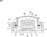
- FIG. 19 is a front sectional view of a camera according to a modification of the third embodiment.
- FIG. 20 is a front sectional view of a camera according to the fourth embodiment of the present invention.
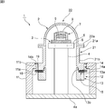
- FIG. 1 is a schematic front cross-sectional view of a camera according to a first embodiment of the present invention
- FIG. 2 is a perspective view of a vibration device used in the first embodiment.
- the camera 1 includes a vibration device 2 that also serves as a camera cover, and a camera body 3 housed in the vibration device 2.
- the camera body 3 has a cylindrical body member 4.
- the lower end of the main body member 4 is fixed to the base plate 4a.
- An imaging unit 5 is fixed to the upper end of the main body member 4.
- a circuit 6 including an image sensor is built in the imaging unit 5.
- the lens module 7 is fixed so as to face the imaging unit 5.
- the lens module 7 is formed of a cylindrical body, and a plurality of lenses 9 are provided therein.
- the structure of the camera body 3 is not particularly limited as long as an object to be imaged located in front of the lens 9 can be imaged.
- the vibration device 2 has a cylindrical case member 11.
- the cylindrical case member 11 is cylindrical.
- the case member 11 may have other shapes such as a rectangular tube shape.
- the case member 11 is made of, for example, metal or synthetic resin.
- the lower end of the case member 11 is fixed to the base plate 4a.
- a cylindrical projecting portion 11a projecting radially inward is provided on the upper end side of the case member 11.
- a cylindrical concave portion 11b is provided on the upper surface of the protruding portion 11a.
- the cylindrical vibrating body 12 is fixed to the case member 11.
- the cylindrical vibrating body portion 12 has a cylindrical shape.
- the cylindrical vibrating body portion 12 includes a cylindrical piezoelectric vibrator 15, a cylindrical first cylindrical member 13, and a cylindrical second cylindrical member 14.
- the cylindrical piezoelectric vibrator 15 includes cylindrical piezoelectric plates 16 and 17.
- the direction of the arrow in the figure is the polarization direction. That is, in the thickness direction, the polarization direction of the piezoelectric plate 16 and the polarization direction of the piezoelectric plate 17 are opposite to each other.
- a cylindrical terminal 18 is sandwiched between the piezoelectric plates 16 and 17.
- a cylindrical terminal 19 is sandwiched between the piezoelectric plate 16 and the second cylindrical member 14.
- the cylindrical vibrating body portion and the cylindrical piezoelectric vibrator may have a rectangular tube shape as well as a cylindrical shape.
- a cylindrical or ring shape is used.
- the piezoelectric plates 16 and 17 are made of lead zirconate titanate piezoelectric ceramics. However, other piezoelectric ceramics such as (K, Na) NbO 3 may be used. Furthermore, a piezoelectric single crystal such as LiTaO 3 may be used.
- Electrodes are formed on both surfaces of the piezoelectric plates 16 and 17.
- This electrode has a laminated structure of, for example, Ag / NiCu / NiCr.
- the terminal 18 is arranged so as to be in contact with the inner electrode in the stacking direction of the piezoelectric plates 16 and 17.
- the terminal 18 is made of an appropriate conductive material. As such a conductive material, Cu, Ag, Al, or an alloy mainly composed of these can be preferably used.
- a cylindrical first cylindrical member 13 is fixed to the lower surface of the piezoelectric vibrator 15.
- the 1st cylinder member 13 has the cylindrical mounting part 13a opened toward the radial direction outer side.
- a piezoelectric vibrator 15 is disposed on the mounting portion 13a.
- a male screw portion 13b is provided on the outer peripheral surface above the radially inner end of the mounting portion 13a.
- the first cylindrical member 13 is made of metal.
- the metal duralumin, stainless steel or kovar can be used.
- the 1st cylinder member 13 may consist of semiconductors, such as Si which has electroconductivity.
- a second cylinder member 14 is disposed on the first cylinder member 13.
- the second cylinder member 14 has a lower end surface 14a.
- a cylindrical lower end surface 14 a is in contact with the upper surface of the piezoelectric vibrator 15. That is, the piezoelectric vibrator 15 is sandwiched between the lower end surface 14a and the mounting portion 13a described above.
- the first cylinder member 13 and the second cylinder member 14 are both made of metal and have conductivity. By applying an alternating electric field between the terminal 18 and the terminal 19, the piezoelectric vibrator 15 can be vibrated longitudinally or laterally.
- a female screw portion is formed on the inner peripheral surface.
- the first cylinder member 13 is screwed into the second cylinder member 14, and the first cylinder member 13 is fixed to the second cylinder member 14.
- the lower end surface 14 a and the mounting portion 13 a described above are pressed against the upper surface and the lower surface of the piezoelectric vibrator 15.
- the entire cylindrical vibrating body portion 12 vibrates efficiently.
- the cylindrical vibrating body portion 12 is efficiently excited by the longitudinal effect or the lateral effect.
- a mode conversion coupling portion 21 is provided integrally with the second cylindrical member 14.
- the second cylindrical member 14 and the mode conversion coupling portion 21 are made of metal and are linked together.
- bond part 21 may be comprised by another member.
- the mode conversion coupling portion 21 and the cylindrical vibrating body 12 are connected as long as the mode of the vibration can be converted and expanded.
- the structure is not particularly limited.
- a flange portion 14b projecting outward is provided on the upper surface of the second cylindrical member 14.
- the flange portion 14b is placed and fixed on the concave portion 11b of the case member 11 described above.
- the cylindrical vibrating body portion 12 described above is configured so that the portion where the flange portion 14b is provided becomes a vibration node. Therefore, even if the flange portion 14b is fixed to the case member 11, the vibration of the cylindrical vibrating body portion 12 is hardly impaired.
- the mode conversion coupling part 21 has a cylindrical shape in this embodiment.
- the mode conversion coupling unit 21 may have another shape such as a square tube.
- bond part 21 can be suitably deform
- the mode conversion coupling portion 21 is made of metal.
- the metal is not particularly limited, and an appropriate metal such as stainless steel, duralumin, and kovar can be used. Alternatively, a conductive semiconductor material such as Si may be used instead of metal. However, in order to enhance the vibration mode conversion and the amplitude expansion action in the mode conversion coupling portion, it is preferable to be made of a material with little vibration loss.
- the mode conversion coupling unit 21 performs vibration mode conversion and vibration expansion when transmitting vibration generated in the cylindrical vibrating body 12 to the light transmitting body described below.
- flange portions 21a projecting outward are provided.
- a lower part connected to the flange portion 21a is a thin portion 21b.
- the thickness of the thin portion 21b is thinner than the thickness of the cylindrical vibrating body portion 12. Therefore, the cylindrical thin-walled portion 21b is largely displaced by the vibration transmitted from the cylindrical vibrating body portion 12. Due to the presence of the thin wall portion 21b, vibration, particularly amplitude can be increased.
- the thin part 21b may be provided in at least one part below the flange part 21a. Further, when the flange portion 21a is not provided, the thin portion 21b may be provided on at least a part of the tubular mode conversion coupling portion 21.
- the thin portion 21b is preferably configured to have a cylindrical shape in the cylindrical mode conversion coupling portion 21.
- the translucent part 22 is fixed on the flange part 21a.
- the translucent part 22 has an opening that opens downward.
- a flange portion 22a is provided so as to project outward from the opening opened downward.
- the flange portion 22a is joined to the flange portion 21a.
- the bonding is performed using an adhesive or a brazing material. Further, thermocompression bonding or anodic bonding may be used.
- the translucent part 22 has a dome shape extending upward from the inner end of the flange part 22a.
- the dome shape is a hemispherical shape.
- the camera body 3 has a viewing angle of 170 °, for example.
- the dome shape is not limited to the hemispherical shape.
- the hemisphere may have a shape in which a cylinder is connected, a curved surface shape smaller than the hemisphere, or the like.
- the translucent body part 22 the whole has translucency.
- the light transmitting body portion 22 is made of glass. But it may be comprised not only with glass but with transparent plastics. Or you may be comprised with the translucent ceramics. However, depending on the application, it is preferable to use tempered glass. Thereby, the strength can be increased. Furthermore, in the case of glass, a coating layer made of DLC or the like may be formed on the surface in order to increase the strength.
- the lens module 7 described above is disposed in the light transmitting body 22. An external object to be imaged is photographed through the translucent part 22.
- the entire translucent body 22 has translucency. But the translucent part may be arrange
- a hydrophobic film is desirably formed on the outer surface of the translucent part 22 in order to prevent water droplets from adhering more preferentially.
- the piezoelectric vibrator 15 When the camera 1 is placed outdoors, for example, water droplets due to rain or the like may adhere to the surface of the translucent body 22. In order to remove the water droplets, the piezoelectric vibrator 15 is driven. That is, an alternating electric field is applied to the piezoelectric vibrator 15.
- the AC electric field is not particularly limited, but a current such as a sine wave sufficient to remove water droplets is applied.
- the piezoelectric vibrator 15 vibrates in the longitudinal vibration mode or the transverse vibration mode.
- the cylindrical vibrating body portion 12 having the first cylindrical member 13 and the second cylindrical member 14 integrated with the piezoelectric vibrator 15 vibrates due to a vertical effect or a lateral effect. In this lateral effect, the cylindrical vibrating body portion 12 vibrates in the breathing vibration mode.
- the longitudinal effect the cylindrical vibrating body portion 12 vibrates in the longitudinal vibration mode.
- the resonance frequency of the vibration mode of the longitudinal effect and the lateral effect of the cylindrical vibrating body portion 12 and the resonance frequency of the vibration mode of the light transmitting body portion 22 are substantially the same. It is desirable to do it.
- the vibration of the cylindrical vibrating body portion 12 is transmitted to the mode conversion coupling portion 21.
- the mode conversion coupling unit 21 converts the vibration mode and expands the amplitude.
- the light transmitting body portion 22 vibrates greatly, the water droplets are atomized, and the water droplets attached to the outer surface of the light transmitting body portion 22 can be eliminated.
- the adhering water droplet can be directly scattered from the outer surface of the transparent body part 22, or can be made to flow down below. As a result, water droplets can be advantageously removed.
- the vibration device 2 is characterized in that a vibration larger than the vibration of the cylindrical vibrating body portion 12 is generated in the light transmitting body portion 22 because the mode conversion coupling portion 21 is provided. Thereby, the load on the piezoelectric vibrator 15 can be reduced. That is, water droplets can be removed preferentially without greatly deforming the piezoelectric vibrator 15.
- FIG. 4 shows the relationship between the resonance characteristics when the frequency for driving the piezoelectric vibrator 15 is variously changed and the amount of displacement of the vertex of the translucent part.
- the solid line in FIG. 4 indicates the resonance characteristics, and the broken line indicates the amount of displacement of the vertex.
- the cylindrical vibrating body 12 is vibrating in the breathing vibration mode due to the lateral effect, and the translucent body 22 is displaced in the bending vibration mode.
- the mode conversion coupling unit 21 converts the breathing vibration mode into the bending vibration mode.
- the big displacement amount is obtained in the vertex of the translucent body part 22 as shown by the arrow A of FIG. That is, the mode conversion coupling unit 21 converts the vibration mode and expands the amplitude.
- the displacement amounts in the portions V1 to V6 in FIG. 5 were obtained by simulation and were as follows.
- Part V1 The range of 0 to 2.3 ⁇ m.
- Part V2 The range of 0 to 2.3 ⁇ m.
- Part V3 The range of 0 to 4.6 ⁇ m.
- Part V4 The range of 4.6 to 13.8 ⁇ m.
- Part V5 The range of 18.4 to 20.7 ⁇ m.
- Part V6 The range of 20.7 to 23.0 ⁇ m.
- the above-mentioned displacement amount is a result of simulation when the dimensions of the cylindrical vibrating body portion 12, the mode conversion coupling portion 21, and the light transmitting body portion 22 are as follows.
- Dimensions of cylindrical vibrator 12 inner diameter 22.0mm, outer diameter 32.0mm, length 11.2mm
- Dimensions of mode conversion coupling part 21 inner diameter 22.0 mm, outer diameter 28.0 mm, length 11.2 mm
- Dimensions of translucent part 22 spherical shell inner diameter 22.0 mm, thickness 1.0 mm
- the cylindrical vibrating body portion 12 vibrates in the breathing vibration mode due to the lateral effect. That is, the cylindrical vibrating body portion 12 vibrates so as to become smaller or larger in the radial direction.
- the translucent body 22 repeats the displacement indicated by the solid line and the broken line. That is, it vibrates in the higher order mode of the bending vibration mode. Even in this case, as shown by an arrow B in FIG. 4, a large amount of displacement is obtained.
- Part V1 Range of 0 to 1.5 ⁇ m.
- Part V2 The range of 0 to 1.5 ⁇ m.
- Part V3 The range of 0 to 1.5 ⁇ m.
- Part V4 The range of 3.0 to 9.0 ⁇ m.
- Part V5 The range of 7.5 to 12.0 ⁇ m.
- Part V6 The range of 12.0 to 15.0 ⁇ m.
- the cylindrical vibrating body portion 12 vibrates in the respiratory vibration mode due to the lateral effect.
- the translucent body part 22 which is a dome part vibrates between the state shown with a continuous line, and the state shown with a broken line, and also vibrates in the higher order mode of the bending vibration mode. Also in this case, as shown by the arrow C in FIG.
- Part V1 is in the range of 0 to 1.2 ⁇ m.
- Part V2 The range of 0 to 1.2 ⁇ m.
- Part V3 The range of 0 to 2.4 ⁇ m.
- Part V4 The range of 2.4 to 8.4 ⁇ m.
- Part V5 The range of 7.2 to 10.8 ⁇ m.
- Part V6 The range of 9.6 to 12.0 ⁇ m.
- the cylindrical vibrating body portion 12 vibrates in the respiratory vibration mode due to the lateral effect.
- the translucent part 22 vibrates between the state indicated by the solid line and the state indicated by the broken line, that is, in the higher-order mode of the respiratory vibration mode. Even in this case, as shown by the arrow D in FIG.
- Part V1 The range of 0 to 1.1 ⁇ m.
- Part V2 The range of 0 to 1.1 ⁇ m.
- Part V3 The range of 0 to 1.1 ⁇ m.
- Part V4 The range of 0 to 5.5 ⁇ m.
- Part V5 The range of 5.5 to 8.8 ⁇ m.
- Part V6 The range of 7.7 to 11.0 ⁇ m.
- the cylindrical vibrating body portion 12 vibrates in the respiratory vibration mode due to the lateral effect.
- the translucent body 22 repeats the state indicated by the solid line and the state indicated by the broken line. That is, it can be seen that the vibration is in the higher order mode of the bending vibration mode. Also in this case, as shown by the arrow E, it can be seen that a large amount of displacement is obtained.
- Part V1 The range of 0 to 1.8 ⁇ m.
- Part V2 The range of 0 to 1.8 ⁇ m.
- Part V3 The range of 0 to 1.8 ⁇ m.
- Part V4 The range of 1.8 to 10.8 ⁇ m.
- Part V5 The range of 3.6 to 14.4 ⁇ m.
- Part V6 The range of 7.7 to 11.0 ⁇ m.
- the cylindrical vibrating body portion 12 vibrates in the longitudinal vibration mode due to the longitudinal effect.
- the translucent part 22 vibrates in the breathing vibration mode.
- the amount of displacement of the vertex of the light transmitting body portion 22 is sufficiently large.
- Part V1 The range of 0 to 0.45 ⁇ m.
- Part V2 The range of 0 to 0.45 ⁇ m.
- Part V3 The range of 0 to 0.90 ⁇ m.
- Part V4 The range of 0.45 to 3.15 ⁇ m.
- Part V5 The range of 3.15 to 3.60 ⁇ m.
- Part V6 The range of 3.60 to 4.50 ⁇ m.
- the mode conversion coupling unit 21 can sufficiently increase the amplitude, and as described above, water droplets can be removed preferentially and the load on the piezoelectric vibrator 15 can be reduced.
- a solution other than water such as ethanol, an aqueous solution in which salt or anti-freezing agent (calcium chloride) is dissolved, a droplet containing impurities that are not soluble in water such as muddy water, or a colloid such as coffee Even a solution or the like (hereinafter referred to as a droplet) can be similarly removed.
- the light transmitting body portion 22 is greatly vibrated to atomize the liquid droplets while the contents are dissolved, and the liquid droplets attached to the outer surface of the light transmitting body portion 22 are removed. Can do. The action at this time is different from evaporation, and it is possible to eliminate the entire droplet without causing the lysate / impurities in the droplet to precipitate.
- the results of the first experiment are shown below.
- the dimensions of the cylindrical vibrating body portion 12, the mode conversion coupling portion 21, and the light transmitting body portion 22 used in the first experiment are as follows.
- Dimension of cylindrical vibrator portion 12 inner diameter 8.0 mm, outer diameter 18.0 mm, length 16.0 mm.
- the dimensions of the mode conversion coupling portion 21 inner diameter 8.0 mm, outer diameter 18.0 mm, length 5.7 mm.
- the dimensions of the translucent part 22 a spherical shell inner diameter of 8.0 mm and a thickness of 1.0 mm.
- salt water an aqueous solution in which 14 g of NaCl is dissolved in 1 liter of water
- 15 ml of salt water was added dropwise in one hour. Even in this case, the aqueous solution could be eliminated without precipitation of NaCl contained in the salt water.
- colloidal solution such as coffee or the solution other than water such as ethanol can also be used to eliminate the solution adhering to the outer surface of the light transmitting portion 22 without causing the contents to deposit on the light transmitting portion 22. I was able to.
- the water droplets are atomized together with the impurities that do not dissolve in water by installing this device in an appropriate direction (downward).
- the water droplets adhering to the outer surface 22 can be eliminated.
- impurities may remain in the translucent part 22, but such residue falls due to its own weight and vibration generated in the translucent part 22. There is no possibility of obscuring the visual field of the translucent part 22.
- the results of the second experiment are shown below.
- the dimensions of the cylindrical vibrating body portion 12, the mode conversion coupling portion 21, and the translucent portion 22 used in the second experiment are the same as those used in the first experiment.
- this apparatus is arranged in a direction inclined 45 ° below the horizontal direction, and droplets in which 10 g of general soil is dispersed in 90 ml of water are dropped little by little on the translucent part 22 to continuously fog
- the impurities having a small particle diameter were atomized together with water and disappeared from the outer surface of the light transmitting member 22.
- impurities having a large particle size remain in the light transmitting member 22, but after a certain period of time, they dropped and were removed from the outer surface of the light transmitting member 22.
- the thickness of the first cylindrical member 13 and the thickness of the second cylindrical member 14 are equal, and the piezoelectric vibrator 15 is provided at the center of the cylindrical vibrating body portion 12 in the thickness direction.
- the configuration of the cylindrical vibrating body portion is not limited to this.
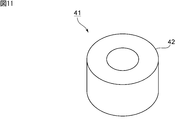
- FIG. 11 is a perspective view showing a modification of the cylindrical vibrating body portion.
- the cylindrical vibrating body portion 41 shown in FIG. 11 the cylindrical vibrating body portion is constituted only by the cylindrical piezoelectric body 42. That is, the thickness of the piezoelectric vibrator 15 in the first embodiment is sufficiently large, and the first cylinder member 13 and the second cylinder member 14 are omitted. As described above, the cylindrical vibrating body portion 41 may be provided only by the piezoelectric vibrator.
- FIG. 12 is a perspective view showing another modification of the cylindrical vibrating body portion.
- a cylindrical member 45 made of metal or the like is bonded to one surface of a cylindrical piezoelectric vibrator 44.
- a unimorph type cylindrical vibrating body portion in which a metal plate is bonded to one surface of the cylindrical piezoelectric vibrator 44 may be used.
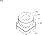
- FIG. 13 is a perspective view for explaining the cylindrical vibrating body portion and the mode conversion coupling portion in the vibration device according to the second embodiment of the present invention.
- a square cylindrical tubular vibrating body portion 12 ⁇ / b> A is provided in the second embodiment.
- the rectangular cylindrical cylindrical vibrating body portion 12A has a square shape in plan view and has a square opening.
- the piezoelectric vibrator 15A also has a rectangular frame shape.
- Such a rectangular cylindrical tubular vibrating body portion 12A may be used.
- the mode conversion coupling portion 21A is also a rectangular tube shape and has a rectangular opening 21c.
- a flange portion 21a that protrudes outward is provided at the upper end of the mode conversion coupling portion 21A.
- the thickness of the mode conversion coupling portion 21A is made thinner than the thickness of the cylindrical vibrating body portion 12A. That is, the entire mode conversion coupling portion 21A constitutes a thin portion.
- the translucent member 22 shown in FIG. 1 is fixed on the flange portion 21a.
- the cylindrical vibrating body portion 12A and the mode conversion coupling portion 21A may have a rectangular tube shape instead of a cylindrical shape.
- FIGS. 14 (a) and 4 (b) to 17 (a) and 17 (b) respectively show the first to eighth combinations of the combination of the cylindrical vibrator portion and the mode conversion coupling portion in the present invention. It is a schematic front sectional drawing which shows the modification of these.
- a cylindrical mode conversion coupling portion 21B is connected to a cylindrical tubular vibrating body portion 12.
- the outer diameter of the mode conversion coupling portion 21 ⁇ / b> B is made equal to the outer diameter of the cylindrical vibrating body portion 12.
- the inner diameter of the mode conversion coupling portion 21 ⁇ / b> B is made larger than the inner diameter of the cylindrical vibrating body portion 12.
- the cylindrical vibrating body portion 12 and the mode conversion coupling portion 21C are cylindrical.
- the outer diameter of the mode conversion coupling portion 21 ⁇ / b> C is made smaller than the outer diameter of the cylindrical vibrating body portion 12.
- the inner diameter of the cylindrical vibrating body portion 12 and the inner diameter of the mode conversion coupling portion 21C are made equal.
- the entire mode conversion coupling portion 21C constitutes a thin portion.
- the cylindrical vibrating body portion 12 may be a rectangular tube shape instead of a cylindrical shape.
- the mode conversion coupling portions 21B and 21C may also have a rectangular tube shape.
- the mode conversion coupling portion 21D is tapered so that the outer diameter decreases as the distance from the cylindrical vibration body portion 12 increases.
- the mode conversion coupling unit may be tapered as in the mode conversion coupling unit 21D.
- the portion where the thickness of the mode conversion coupling portion 21D is thinner than the thickness of the cylindrical vibrator portion 12 corresponds to the thin portion.
- a portion of the mode conversion coupling portion 21E whose thickness is thinner than the cylindrical vibrating body portion 12 constitutes a thin portion.
- the hollow area of the mode conversion coupling part 21E is configured so that its cross-sectional area increases as the distance from the cylindrical vibrating body part 12 increases.
- the wall thickness may be changed so as to become thinner as the distance from the cylindrical vibrating body portion 12 increases.
- an inner flange portion 21d projecting inward is provided at the upper end of the mode conversion coupling portion 21B1. Accordingly, the opening area of the opening 21e is made smaller than the hollow space of the mode conversion coupling portion 21B1.
- the lower part than the inner flange part 21d of the mode conversion coupling part 21B1 constitutes a thin part.
- the flange portion 21a protruding outward may be provided at the upper end of the mode conversion coupling portion 21F in the same manner as in the first embodiment.
- the mode conversion coupling portion 21G has a structure similar to that of the mode conversion coupling portion 21D shown in FIG. 15A, except that the flange protrudes outward at the upper end. A portion 21a is provided. Thus, you may provide the flange part 21a in the upper end of the part to which the taper is provided.
- an inner flange portion 21d projecting inward is provided on the upper end side of the same structure as the mode conversion coupling portion 21E shown in FIG. 15B. It has been. Thereby, the area of the opening 21e is reduced.
- portions where the thickness is thinner than the thickness of the cylindrical vibrating body portion 12 are thin portions.
- the shapes of the cylindrical vibrator portion 12 and the mode conversion coupling portion can be modified into various forms.
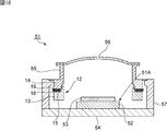
- FIG. 18 is a front sectional view of a camera according to the third embodiment of the present invention.
- a camera 51 according to the third embodiment includes a vibration device and a camera body housed in the vibration device.
- the camera body has a body member 51A.
- the main body member 51 ⁇ / b> A is fixed to the base plate 54.
- the camera main body includes a circuit board 52 provided on the main body member 51 ⁇ / b> A and an image sensor 53 provided on the circuit board 52.
- a lens 56 is installed so as to face the image sensor 53.
- This lens 56 has a convex outer surface and a concave inner surface. That is, the inner surface protrudes outward. Accordingly, the lens 56 has a curved outer surface as in the case of the light transmitting member 22 of the first embodiment.
- the viewing angle of the lens 56 is 160 °, for example.
- One end of a mode conversion coupling portion 55 to be described later is joined to the outer peripheral edge of the lens 56.
- the vibration device 51 has a cylindrical case member 57.
- the cylindrical case member 57 is cylindrical.
- the case member 57 may have other shapes such as a rectangular tube shape.
- the case member is made of, for example, metal or synthetic resin.
- the lower end of the case member 57 is fixed to the base plate 54.
- a cylindrical projecting portion projecting radially inward is provided on the upper end side of the case member 57.
- a cylindrical recess is provided on the upper surface of the protrusion.
- the cylindrical vibrating body 12 is fixed to the case member 57.
- the cylindrical vibrating body portion 12 has a cylindrical shape. Similar to the first embodiment, the cylindrical vibrating body portion 12 includes a cylindrical piezoelectric vibrator 15, a cylindrical first cylindrical member 13, and a cylindrical second cylindrical member 14.
- the first cylindrical member 13 is fixed to one main surface of the piezoelectric vibrator 15.
- a second cylindrical member 14 is disposed on the other main surface of the first cylindrical member 13. Due to the vibration generated in the piezoelectric vibrator 15, the entire cylindrical vibrator portion 12 vibrates efficiently. In the present embodiment, the cylindrical vibrating body portion 12 is efficiently excited by the longitudinal effect or the lateral effect.
- a mode conversion coupling portion 55 similar to that of the first embodiment is provided integrally with the second cylindrical member 14.
- the second cylindrical member 14 and the mode conversion coupling portion 55 are made of metal and are linked together.
- the outer peripheral edge of the lens 56 is joined to one end of the mode conversion coupling portion 55.
- the cylindrical vibrating body portion 12 is coupled to the other end of the mode conversion coupling portion 55.
- the mode conversion coupling portion 55 has a thin portion that is thinner than the cylindrical vibrating body portion 12.
- the entire thickness of the mode conversion coupling portion 55 is made thinner than that of the cylindrical vibrating body portion 12 so that the whole is a thin portion.
- the mode conversion coupling unit 55 is configured in the same manner as the mode conversion coupling unit 21 in the first embodiment. That is, it is configured to convert the vibration mode of the cylindrical vibrating body portion 12 and to expand the vibration. Thereby, a large vibration is given to the lens 56.
- the resonance frequency of the vibration mode in the cylindrical vibrating body portion 12 and the resonance frequency of the vibration in the lens 56 are substantially matched. Thereby, the vibration can be expanded more effectively.
- the vibration of the cylindrical vibrating body portion 12 may be in a longitudinal vibration mode or a lateral vibration mode, as in the case of the first embodiment.
- the vibration mode of the lens 56 may be bending vibration or respiratory vibration mode, and is not particularly limited.
- the lens 56 is vibrated greatly, and water droplets attached to the outer surface of the lens 56 can be removed or allowed to flow down. In this way, the vibration device may be configured to have the lens 56 itself.
- the camera 51 according to the third embodiment of the present invention includes one lens 56, but as shown in FIG. 19, it is separately provided for adjusting the optical path between the lens 56 and the image sensor 53.
- a lens module 61 may be provided.
- the lens module 61 includes a cylindrical body and a plurality of lenses 62a to 62c arranged in the cylindrical body.
- the lens module 61 is provided on the base plate 54. Instead of the lens module 61, one or more lenses may be disposed between the lens 56 and the image sensor 53.
- a convex lens 72 may be joined to the mode conversion coupling portion 55.
Landscapes
- Physics & Mathematics (AREA)
- General Physics & Mathematics (AREA)
- Engineering & Computer Science (AREA)
- Mechanical Engineering (AREA)
- Optics & Photonics (AREA)
- Studio Devices (AREA)
- Accessories Of Cameras (AREA)
- General Electrical Machinery Utilizing Piezoelectricity, Electrostriction Or Magnetostriction (AREA)
- Camera Bodies And Camera Details Or Accessories (AREA)
- Lens Barrels (AREA)
- Piezo-Electric Transducers For Audible Bands (AREA)
Abstract
L'invention concerne un dispositif vibrant capable d'éliminer avantageusement les gouttes d'eau et éléments similaires adhérant à un capot ou à une lentille, sans imposer de charge importante à un vibreur piézoélectrique. Le dispositif vibrant 2 est utilisé dans un corps de caméra qui comprend un objectif 9. Le dispositif vibrant comprend : une partie de corps vibrant tubulaire 12 dotée d'un vibreur piézoélectrique 15 ; une partie de couplage tubulaire à conversion de mode 21 couplée à une extrémité de la partie de corps vibrant tubulaire 12 ; et une partie de corps translucide 22 unie à la partie de couplage de conversion de mode 21. La partie de corps translucide 22 comprend une partie translucide disposée devant l'objectif 9. La partie de couplage à conversion de mode 21 comprend une partie à paroi mince ayant une épaisseur qui est inférieure à celle de la partie de corps vibrant tubulaire 12.
Priority Applications (4)
| Application Number | Priority Date | Filing Date | Title |
|---|---|---|---|
| CN201680040944.9A CN107852449B (zh) | 2015-08-04 | 2016-06-30 | 振动装置以及摄像头 |
| EP16832661.9A EP3276940B1 (fr) | 2015-08-04 | 2016-06-30 | Dispositif vibrant et caméra |
| JP2017532436A JP6418330B2 (ja) | 2015-08-04 | 2016-06-30 | 振動装置及びカメラ |
| US15/832,853 US10156719B2 (en) | 2015-08-04 | 2017-12-06 | Vibration device and camera |
Applications Claiming Priority (2)
| Application Number | Priority Date | Filing Date | Title |
|---|---|---|---|
| JP2015-154022 | 2015-08-04 | ||
| JP2015154022 | 2015-08-04 |
Related Child Applications (1)
| Application Number | Title | Priority Date | Filing Date |
|---|---|---|---|
| US15/832,853 Continuation US10156719B2 (en) | 2015-08-04 | 2017-12-06 | Vibration device and camera |
Publications (1)
| Publication Number | Publication Date |
|---|---|
| WO2017022382A1 true WO2017022382A1 (fr) | 2017-02-09 |
Family
ID=57942921
Family Applications (1)
| Application Number | Title | Priority Date | Filing Date |
|---|---|---|---|
| PCT/JP2016/069399 WO2017022382A1 (fr) | 2015-08-04 | 2016-06-30 | Dispositif vibrant et caméra |
Country Status (5)
| Country | Link |
|---|---|
| US (1) | US10156719B2 (fr) |
| EP (1) | EP3276940B1 (fr) |
| JP (1) | JP6418330B2 (fr) |
| CN (1) | CN107852449B (fr) |
| WO (1) | WO2017022382A1 (fr) |
Cited By (19)
| Publication number | Priority date | Publication date | Assignee | Title |
|---|---|---|---|---|
| JPWO2017110563A1 (ja) * | 2015-12-24 | 2018-09-06 | 株式会社村田製作所 | 振動装置及びその駆動方法並びにカメラ |
| JP2018145059A (ja) * | 2017-03-07 | 2018-09-20 | オリエントブレイン株式会社 | ドームガラスの製造方法、空冷装置及びドームガラス |
| WO2018198417A1 (fr) * | 2017-04-28 | 2018-11-01 | 株式会社村田製作所 | Dispositif de vibration |
| WO2018207395A1 (fr) * | 2017-05-12 | 2018-11-15 | 株式会社村田製作所 | Dispositif de vibration |
| WO2019101388A1 (fr) * | 2017-11-24 | 2019-05-31 | Echovista Gmbh | Dispositif de surveillance optique |
| WO2019130623A1 (fr) * | 2017-12-27 | 2019-07-04 | 株式会社村田製作所 | Dispositif vibratoire et dispositif de détection optique |
| CN110546941A (zh) * | 2017-04-24 | 2019-12-06 | 株式会社村田制作所 | 清洗装置和具备清洗装置的摄像单元 |
| CN110574358A (zh) * | 2017-04-26 | 2019-12-13 | 株式会社村田制作所 | 清洗装置以及具备清洗装置的摄像单元 |
| WO2020003571A1 (fr) * | 2018-06-28 | 2020-01-02 | 株式会社村田製作所 | Dispositif de vibration |
| WO2020003572A1 (fr) * | 2018-06-28 | 2020-01-02 | 株式会社村田製作所 | Dispositif de vibration et dispositif de détection optique |
| JPWO2019009336A1 (ja) * | 2017-07-05 | 2020-04-30 | Agc株式会社 | センサモジュール及び保護ガラス |
| JPWO2020003573A1 (ja) * | 2018-06-28 | 2021-02-15 | 株式会社村田製作所 | 振動装置及び光学検出装置 |
| WO2021038942A1 (fr) * | 2019-08-28 | 2021-03-04 | 株式会社村田製作所 | Dispositif de vibration et dispositif de détection optique |
| JPWO2021192387A1 (fr) * | 2020-03-27 | 2021-09-30 | ||
| JPWO2021229853A1 (fr) * | 2020-05-15 | 2021-11-18 | ||
| JPWO2021229852A1 (fr) * | 2020-05-15 | 2021-11-18 | ||
| WO2021229853A1 (fr) * | 2020-05-15 | 2021-11-18 | 株式会社村田製作所 | Dispositif de vibration |
| JP7070497B2 (ja) | 2019-04-25 | 2022-05-18 | 株式会社村田製作所 | 振動装置及び光学検出装置 |
| EP4147797A1 (fr) * | 2021-09-09 | 2023-03-15 | Texas Instruments Incorporated | Conceptions de support pour nettoyage de lentille ultrasonore |
Families Citing this family (12)
| Publication number | Priority date | Publication date | Assignee | Title |
|---|---|---|---|---|
| WO2017022382A1 (fr) * | 2015-08-04 | 2017-02-09 | 株式会社村田製作所 | Dispositif vibrant et caméra |
| CN108474998B (zh) * | 2016-03-03 | 2020-10-30 | 株式会社村田制作所 | 振动装置及其驱动方法、以及摄像头 |
| JP6597897B2 (ja) * | 2016-06-24 | 2019-10-30 | 株式会社村田製作所 | 振動装置及び撮像装置 |
| CN109643044B (zh) * | 2016-11-30 | 2021-01-01 | 株式会社村田制作所 | 振动装置、摄像机用水滴去除装置以及摄像机 |
| WO2019153293A1 (fr) * | 2018-02-11 | 2019-08-15 | 深圳市大疆创新科技有限公司 | Dispositif panoramique-basculant et son procédé de commande, et véhicule aérien sans pilote |
| WO2020066088A1 (fr) * | 2018-09-28 | 2020-04-02 | 株式会社村田製作所 | Dispositif de vibration et appareil de détection optique |
| EP3934227A4 (fr) * | 2019-04-26 | 2022-11-09 | Murata Manufacturing Co., Ltd. | Dispositif de nettoyage, unité d'imagerie à dispositif de nettoyage, et procédé de nettoyage |
| US11489988B2 (en) | 2019-05-06 | 2022-11-01 | H.P.B. Optoelectronics Co., Ltd. | Method for removing foreign substances from a camera system using vibration of piezoelectric component, and camera system comprising the piezoelectric component |
| JP7396824B2 (ja) * | 2019-07-02 | 2023-12-12 | 株式会社ディスコ | 超音波水噴射装置 |
| US11448873B2 (en) | 2019-09-23 | 2022-09-20 | Cnh Industrial Canada, Ltd. | System and method for cleaning vision sensors of an agricultural machine |
| EP3852354B1 (fr) * | 2019-11-22 | 2023-10-25 | Murata Manufacturing Co., Ltd. | Dispositif de vibration, et unité d'imagerie comprenant ce dispositif de vibration |
| CN114206516B (zh) * | 2020-04-30 | 2023-07-04 | 株式会社村田制作所 | 清洗装置、具备清洗装置的摄像单元以及清洗方法 |
Citations (4)
| Publication number | Priority date | Publication date | Assignee | Title |
|---|---|---|---|---|
| JPH0532191U (ja) * | 1991-10-02 | 1993-04-27 | 株式会社村上開明堂 | モニタ−カメラの水滴除去装置 |
| JPH07151946A (ja) * | 1994-09-12 | 1995-06-16 | Olympus Optical Co Ltd | カメラ |
| JP2879155B2 (ja) * | 1989-11-16 | 1999-04-05 | 耕司 戸田 | 水滴除去装置 |
| JP2013080177A (ja) * | 2011-10-05 | 2013-05-02 | Aisin Seiki Co Ltd | 水滴除去機能付カメラ |
Family Cites Families (16)
| Publication number | Priority date | Publication date | Assignee | Title |
|---|---|---|---|---|
| JP2007082062A (ja) | 2005-09-16 | 2007-03-29 | Denso Corp | 水滴除去装置 |
| JP4344761B2 (ja) * | 2007-06-15 | 2009-10-14 | シャープ株式会社 | 固体撮像装置およびそれを備えた電子機器 |
| US8379333B2 (en) * | 2009-02-23 | 2013-02-19 | Kyocera Corporation | Imaging module |
| JP2012138768A (ja) | 2010-12-27 | 2012-07-19 | Hitachi Kokusai Electric Inc | ドーム型監視カメラシステム |
| WO2012129521A1 (fr) * | 2011-03-23 | 2012-09-27 | Gentex Corporation | Dispositif de nettoyage d'objectif |
| JP5224077B2 (ja) * | 2011-11-07 | 2013-07-03 | 株式会社ニコン | 撮像装置および光学装置 |
| US9436005B2 (en) * | 2012-08-02 | 2016-09-06 | Gentex Corporation | Amplified piezoelectric camera lens cleaner |
| JP5615341B2 (ja) | 2012-12-18 | 2014-10-29 | 三菱電機株式会社 | ドーム型監視カメラ |
| JP2014127998A (ja) * | 2012-12-27 | 2014-07-07 | Olympus Imaging Corp | 振動装置及びこれを備えた画像機器 |
| WO2015072326A1 (fr) * | 2013-11-15 | 2015-05-21 | オリンパスメディカルシステムズ株式会社 | Unité de production de vibrations, unité de corps vibrant et dispositif de traitement par ultrasons |
| US10401618B2 (en) * | 2015-03-11 | 2019-09-03 | Texas Instruments Incorporated | Ultrasonic lens cleaning system with current sensing |
| WO2017022382A1 (fr) * | 2015-08-04 | 2017-02-09 | 株式会社村田製作所 | Dispositif vibrant et caméra |
| WO2017110563A1 (fr) * | 2015-12-24 | 2017-06-29 | 株式会社村田製作所 | Dispositif de vibration, procédé pour piloter ce dernier et caméra |
| JP6579200B2 (ja) * | 2015-12-25 | 2019-09-25 | 株式会社村田製作所 | 振動装置及びカメラ |
| CN108474998B (zh) * | 2016-03-03 | 2020-10-30 | 株式会社村田制作所 | 振动装置及其驱动方法、以及摄像头 |
| JP6597897B2 (ja) * | 2016-06-24 | 2019-10-30 | 株式会社村田製作所 | 振動装置及び撮像装置 |
-
2016
- 2016-06-30 WO PCT/JP2016/069399 patent/WO2017022382A1/fr active Application Filing
- 2016-06-30 EP EP16832661.9A patent/EP3276940B1/fr active Active
- 2016-06-30 CN CN201680040944.9A patent/CN107852449B/zh active Active
- 2016-06-30 JP JP2017532436A patent/JP6418330B2/ja active Active
-
2017
- 2017-12-06 US US15/832,853 patent/US10156719B2/en active Active
Patent Citations (4)
| Publication number | Priority date | Publication date | Assignee | Title |
|---|---|---|---|---|
| JP2879155B2 (ja) * | 1989-11-16 | 1999-04-05 | 耕司 戸田 | 水滴除去装置 |
| JPH0532191U (ja) * | 1991-10-02 | 1993-04-27 | 株式会社村上開明堂 | モニタ−カメラの水滴除去装置 |
| JPH07151946A (ja) * | 1994-09-12 | 1995-06-16 | Olympus Optical Co Ltd | カメラ |
| JP2013080177A (ja) * | 2011-10-05 | 2013-05-02 | Aisin Seiki Co Ltd | 水滴除去機能付カメラ |
Non-Patent Citations (1)
| Title |
|---|
| See also references of EP3276940A4 * |
Cited By (61)
| Publication number | Priority date | Publication date | Assignee | Title |
|---|---|---|---|---|
| JPWO2017110563A1 (ja) * | 2015-12-24 | 2018-09-06 | 株式会社村田製作所 | 振動装置及びその駆動方法並びにカメラ |
| JP2018145059A (ja) * | 2017-03-07 | 2018-09-20 | オリエントブレイン株式会社 | ドームガラスの製造方法、空冷装置及びドームガラス |
| CN110546941A (zh) * | 2017-04-24 | 2019-12-06 | 株式会社村田制作所 | 清洗装置和具备清洗装置的摄像单元 |
| CN110546941B (zh) * | 2017-04-24 | 2022-03-04 | 株式会社村田制作所 | 清洗装置和具备清洗装置的摄像单元 |
| US11511322B2 (en) | 2017-04-24 | 2022-11-29 | Murata Manufacturing Co., Ltd. | Cleaning device and imaging unit including the same |
| CN110574358B (zh) * | 2017-04-26 | 2021-05-28 | 株式会社村田制作所 | 清洗装置以及具备清洗装置的摄像单元 |
| CN110574358A (zh) * | 2017-04-26 | 2019-12-13 | 株式会社村田制作所 | 清洗装置以及具备清洗装置的摄像单元 |
| JPWO2018198417A1 (ja) * | 2017-04-28 | 2019-12-12 | 株式会社村田製作所 | 振動装置 |
| CN110573960A (zh) * | 2017-04-28 | 2019-12-13 | 株式会社村田制作所 | 振动装置 |
| EP3617796A4 (fr) * | 2017-04-28 | 2021-01-06 | Murata Manufacturing Co., Ltd. | Dispositif de vibration |
| US11504742B2 (en) | 2017-04-28 | 2022-11-22 | Murata Manufacturing Co., Ltd. | Vibration device |
| CN110573960B (zh) * | 2017-04-28 | 2022-02-01 | 株式会社村田制作所 | 振动装置 |
| WO2018198417A1 (fr) * | 2017-04-28 | 2018-11-01 | 株式会社村田製作所 | Dispositif de vibration |
| EP3623059A4 (fr) * | 2017-05-12 | 2021-02-24 | Murata Manufacturing Co., Ltd. | Dispositif de vibration |
| JPWO2018207395A1 (ja) * | 2017-05-12 | 2019-12-26 | 株式会社村田製作所 | 振動装置 |
| CN110621418A (zh) * | 2017-05-12 | 2019-12-27 | 株式会社村田制作所 | 振动装置 |
| WO2018207395A1 (fr) * | 2017-05-12 | 2018-11-15 | 株式会社村田製作所 | Dispositif de vibration |
| US11434891B2 (en) | 2017-05-12 | 2022-09-06 | Murata Manufacturing Co., Ltd. | Vibration device |
| US11543271B2 (en) | 2017-07-05 | 2023-01-03 | AGC Inc. | Sensor module and protective glass |
| JPWO2019009336A1 (ja) * | 2017-07-05 | 2020-04-30 | Agc株式会社 | センサモジュール及び保護ガラス |
| JP7147759B2 (ja) | 2017-07-05 | 2022-10-05 | Agc株式会社 | センサモジュール及び保護ガラス |
| US11761799B2 (en) | 2017-07-05 | 2023-09-19 | AGC Inc. | Sensor module and protective glass |
| CN111406229A (zh) * | 2017-11-24 | 2020-07-10 | 艾克维斯塔股份有限公司 | 光学监控设备 |
| EP4220278A1 (fr) * | 2017-11-24 | 2023-08-02 | EchoVista GmbH | Dispositif de surveillance optique |
| US11820337B2 (en) | 2017-11-24 | 2023-11-21 | Echovista Gmbh | Optical monitoring device |
| WO2019101388A1 (fr) * | 2017-11-24 | 2019-05-31 | Echovista Gmbh | Dispositif de surveillance optique |
| WO2019130629A1 (fr) * | 2017-12-27 | 2019-07-04 | 株式会社村田製作所 | Dispositif vibratoire et dispositif de détection optique |
| WO2019130623A1 (fr) * | 2017-12-27 | 2019-07-04 | 株式会社村田製作所 | Dispositif vibratoire et dispositif de détection optique |
| US11012597B2 (en) | 2017-12-27 | 2021-05-18 | Murata Manufacturing Co., Ltd. | Vibrating device and optical detector device |
| EP3664430A4 (fr) * | 2017-12-27 | 2021-04-21 | Murata Manufacturing Co., Ltd. | Dispositif vibratoire et dispositif de détection optique |
| US11503190B2 (en) | 2017-12-27 | 2022-11-15 | Murata Manufacturing Co., Ltd. | Vibration device and optical detection device |
| JPWO2019130623A1 (ja) * | 2017-12-27 | 2020-07-27 | 株式会社村田製作所 | 振動装置及び光学検出装置 |
| CN111512622B (zh) * | 2017-12-27 | 2021-11-16 | 株式会社村田制作所 | 振动装置以及光学检测装置 |
| CN111512623A (zh) * | 2017-12-27 | 2020-08-07 | 株式会社村田制作所 | 振动装置以及光学检测装置 |
| JPWO2019130629A1 (ja) * | 2017-12-27 | 2020-07-27 | 株式会社村田製作所 | 振動装置及び光学検出装置 |
| CN111512622A (zh) * | 2017-12-27 | 2020-08-07 | 株式会社村田制作所 | 振动装置以及光学检测装置 |
| CN111512623B (zh) * | 2017-12-27 | 2021-12-28 | 株式会社村田制作所 | 振动装置以及光学检测装置 |
| US11745219B2 (en) | 2018-06-28 | 2023-09-05 | Murata Manufacturing Co., Ltd. | Vibration apparatus |
| US11796896B2 (en) | 2018-06-28 | 2023-10-24 | Murata Manufacturing Co., Ltd. | Vibration device and optical detection device |
| JP7095740B2 (ja) | 2018-06-28 | 2022-07-05 | 株式会社村田製作所 | 振動装置及び光学検出装置 |
| WO2020003571A1 (fr) * | 2018-06-28 | 2020-01-02 | 株式会社村田製作所 | Dispositif de vibration |
| JPWO2020003572A1 (ja) * | 2018-06-28 | 2021-04-08 | 株式会社村田製作所 | 振動装置及び光学検出装置 |
| JPWO2020003571A1 (ja) * | 2018-06-28 | 2021-02-15 | 株式会社村田製作所 | 振動装置 |
| JPWO2020003573A1 (ja) * | 2018-06-28 | 2021-02-15 | 株式会社村田製作所 | 振動装置及び光学検出装置 |
| WO2020003572A1 (fr) * | 2018-06-28 | 2020-01-02 | 株式会社村田製作所 | Dispositif de vibration et dispositif de détection optique |
| JP7070497B2 (ja) | 2019-04-25 | 2022-05-18 | 株式会社村田製作所 | 振動装置及び光学検出装置 |
| WO2021038942A1 (fr) * | 2019-08-28 | 2021-03-04 | 株式会社村田製作所 | Dispositif de vibration et dispositif de détection optique |
| CN113767616A (zh) * | 2020-03-27 | 2021-12-07 | 株式会社村田制作所 | 振动装置和振动控制方法 |
| JPWO2021192387A1 (fr) * | 2020-03-27 | 2021-09-30 | ||
| CN113767616B (zh) * | 2020-03-27 | 2023-04-04 | 株式会社村田制作所 | 振动装置和振动控制方法 |
| JP7111258B2 (ja) | 2020-03-27 | 2022-08-02 | 株式会社村田製作所 | 振動装置及び振動制御方法 |
| US11754830B2 (en) | 2020-03-27 | 2023-09-12 | Murata Manufacturing Co., Ltd. | Vibration device and vibration control method |
| WO2021192387A1 (fr) * | 2020-03-27 | 2021-09-30 | 株式会社村田製作所 | Dispositif vibration et procédé de commande de vibration |
| JP7099633B2 (ja) | 2020-05-15 | 2022-07-12 | 株式会社村田製作所 | 振動装置 |
| JPWO2021229852A1 (fr) * | 2020-05-15 | 2021-11-18 | ||
| JP7173333B2 (ja) | 2020-05-15 | 2022-11-16 | 株式会社村田製作所 | 振動装置 |
| JPWO2021229853A1 (fr) * | 2020-05-15 | 2021-11-18 | ||
| US11825180B2 (en) | 2020-05-15 | 2023-11-21 | Murata Manufacturing Co., Ltd. | Vibration device |
| WO2021229852A1 (fr) * | 2020-05-15 | 2021-11-18 | 株式会社村田製作所 | Dispositif de vibration |
| WO2021229853A1 (fr) * | 2020-05-15 | 2021-11-18 | 株式会社村田製作所 | Dispositif de vibration |
| EP4147797A1 (fr) * | 2021-09-09 | 2023-03-15 | Texas Instruments Incorporated | Conceptions de support pour nettoyage de lentille ultrasonore |
Also Published As
| Publication number | Publication date |
|---|---|
| US20180095272A1 (en) | 2018-04-05 |
| EP3276940A4 (fr) | 2018-10-24 |
| JP6418330B2 (ja) | 2018-11-07 |
| EP3276940A1 (fr) | 2018-01-31 |
| JPWO2017022382A1 (ja) | 2018-02-15 |
| CN107852449A (zh) | 2018-03-27 |
| US10156719B2 (en) | 2018-12-18 |
| CN107852449B (zh) | 2020-08-18 |
| EP3276940B1 (fr) | 2020-10-07 |
Similar Documents
| Publication | Publication Date | Title |
|---|---|---|
| JP6418330B2 (ja) | 振動装置及びカメラ | |
| JP6665948B2 (ja) | 振動装置、カメラ用水滴除去装置及びカメラ | |
| EP3623059B1 (fr) | Dispositif de vibration | |
| JP6579200B2 (ja) | 振動装置及びカメラ | |
| JP6662391B2 (ja) | 振動装置及びその駆動方法並びにカメラ | |
| CN111512622B (zh) | 振动装置以及光学检测装置 | |
| JP6508415B2 (ja) | 振動装置及びその駆動方法、並びにカメラ | |
| JP6819844B1 (ja) | 振動装置、および振動装置を備える撮像ユニット | |
| JP7111258B2 (ja) | 振動装置及び振動制御方法 | |
| JP2020181079A (ja) | 振動装置及び光学検出装置 | |
| US20190113744A1 (en) | Electromechanical Oscillatory System | |
| US11383274B2 (en) | Vibration device and imaging unit including vibration device | |
| WO2023100397A1 (fr) | Module optique et dispositif optique | |
| WO2020137262A1 (fr) | Dispositif de vibration et dispositif de détection optique |
Legal Events
| Date | Code | Title | Description |
|---|---|---|---|
| 121 | Ep: the epo has been informed by wipo that ep was designated in this application |
Ref document number: 16832661 Country of ref document: EP Kind code of ref document: A1 |
|
| ENP | Entry into the national phase |
Ref document number: 2017532436 Country of ref document: JP Kind code of ref document: A |
|
| REEP | Request for entry into the european phase |
Ref document number: 2016832661 Country of ref document: EP |
|
| NENP | Non-entry into the national phase |
Ref country code: DE |