WO2020054583A1 - 杭施工治具 - Google Patents
杭施工治具 Download PDFInfo
- Publication number
- WO2020054583A1 WO2020054583A1 PCT/JP2019/035042 JP2019035042W WO2020054583A1 WO 2020054583 A1 WO2020054583 A1 WO 2020054583A1 JP 2019035042 W JP2019035042 W JP 2019035042W WO 2020054583 A1 WO2020054583 A1 WO 2020054583A1
- Authority
- WO
- WIPO (PCT)
- Prior art keywords
- pile
- axis direction
- construction jig
- wing
- grip portion
- Prior art date
- Legal status (The legal status is an assumption and is not a legal conclusion. Google has not performed a legal analysis and makes no representation as to the accuracy of the status listed.)
- Ceased
Links
Images


Classifications
-
- E—FIXED CONSTRUCTIONS
- E02—HYDRAULIC ENGINEERING; FOUNDATIONS; SOIL SHIFTING
- E02D—FOUNDATIONS; EXCAVATIONS; EMBANKMENTS; UNDERGROUND OR UNDERWATER STRUCTURES
- E02D13/00—Accessories for placing or removing piles or bulkheads, e.g. noise attenuating chambers
Definitions
- the present invention relates to a pile construction jig arranged in a casing tube rotating device for gripping a pile having a wing extending in a direction perpendicular to a pile axis.
- Patent Document 1 discloses a tubing device in which a spiral groove is formed on an inner peripheral surface of a chuck collar to allow a spiral excavating blade of a rotary pile to pass therethrough.
- Patent Document 2 after operating the chuck cylinder to make the inner diameter between the plurality of chuck collars slightly larger than the diameter of the body of the rotating pile, lifting the rotating pile with a crane to expose the excavating blade to the groove. By passing through and positioned below the chuck collar, operating the chuck cylinder, gripping the body of the rotating pile with the inner peripheral surface of the plurality of chuck collars, and rotating the casing tube rotating device to build the rotating pile A method is disclosed.
- Patent Document 3 in a tubing device in which a chuck plate is detachably provided on an inner peripheral surface of a chuck collar provided in a casing tube insertion hole of the tubing device, the chuck plate is attached to the chuck collar via an attachment seat, Is provided with a pair of end surface contact protrusions that contact the upper and lower end surfaces of the chuck plate on the front side of the mounting seat body, and a pair of side surface contact protrusions that contact the vertical center of both sides of the chuck plate, A tubing device in which a mounting seat fitting groove having upper and lower ends opened on an inner peripheral surface of a chuck collar is formed is disclosed.
- a detaching member is attached to a detaching member attaching concave portion provided on the inner peripheral surface of a chuck collar of a tubing device, a chuck plate is attached to a chuck plate attaching concave portion, and a removing bolt is attached to a female screw hole provided in the detaching member.
- a tubing device that removes the removal member and the chuck plate from each of the mounting recesses by a reaction in which the tip of the removing bolt comes into contact with the bottom surface of the mounting member mounting recess.
- Patent Literature 5 discloses that the pile core deviates from the core of the construction device even in an unstable place such as when the construction site is the seabed ground or the lakebed ground, and furthermore, when the ground surface is inclined obliquely on land or the seabed.
- a rotary press-fitting pile construction device mounted so as to be positioned on the upper side and the lower side of the pile.
- the pile construction jig arranged in the casing tube rotating device is used for gripping the pile.
- the size of the pile construction jig is proportional to the pile diameter and the size of the wing of the pile, and the pile construction jig needs to be formed larger as the pile diameter and the wing of the pile increase.
- the pile construction jig is enlarged, there is a problem in that the bearing force for gripping the pile tends to act unequally in the pile axis direction or the pile axis orthogonal direction.
- the pile construction jig may be tilted due to the backlash of the device, so that only a part of the spiral collar hits the pile and the bearing pressure for gripping the pile. May be uneven. Further, as a result, there is a problem that only a part of the spiral collar is worn. As a result, for example, a problem may occur in which a part of the pile is dented or the pile is damaged due to the uneven pressure.
- Patent Documents 1 to 5 do not disclose or suggest any adverse effects when the pile construction jig as described above is enlarged, nor any countermeasures. For this reason, it is difficult for the disclosed technologies described in Patent Documents 1 to 5 to evenly apply the supporting force for gripping the pile.
- the present invention has been devised in view of the above-described problems, and aims at uniformly applying a supporting pressure for gripping a pile, causing the pile to slip or crush. It is an object of the present invention to provide a pile construction jig which can prevent the pile construction.
- the present invention has been made in view of the above problems, and the gist thereof is as follows.
- a pile construction jig provided in a casing tube rotating device and provided with a spiral collar for gripping a pile having a wing portion projecting in a direction perpendicular to a pile axis, wherein the spiral collar is arranged in a pile axial direction.
- a connecting portion that extends and is connected to the casing tube rotating device, and a grip portion that is joined to the connecting portion and extends in a direction perpendicular to the pile axis, wherein the spiral collar is provided through the grip portion.
- the weight of the connection portion is 1.05 times or more the weight of the grip portion
- the connection portion and the grip portion are divided into two or more along the pile circumferential direction
- the grip portion is divided into two or more divided portions along the pile axis direction, and each of the divided portions faces an outer surface of the pile and forms an angle around a bent portion extending in the pile axis direction.
- Tip surface divided into two regions, and the bent portion Sandwiched therebetween pile construction jig characterized by comprising a pair of contact surfaces arranged flat on the tip surface.
- the length of the grip portion in the direction perpendicular to the pile axis is 0.1 to 1.0 times the diameter of the pile, and the wing portion that protrudes from the pile in the direction perpendicular to the pile axis.
- the spiral collar Longer than the length, has a plurality of grooves for turning the wings between a pair of the divided portions divided along the pile axis direction, and among the plurality of the grooves, Provided at the top in the axial direction, an introductory groove formed stepwise in the pile axial direction with respect to the other adjacent groove along the pile circumferential direction is for invoking the wing, Of the plurality of grooves, a delivery groove formed at the lowest position in the pile axis direction and formed stepwise in the pile axis direction with respect to still another groove adjacent to the circumference of the pile, Sending out the wing swiveled from the groove through the plurality of other grooves Pile construction jig (1) or (2), characterized in that for those of.
- a tubing device provided with the pile construction jig according to any one of the above (1) to (4).
- tip surface of the grip part facing the outer surface of a pile can be easily kept parallel to the pile axial direction, and the grip part is attached to a pile regardless of the size of a pile construction jig.
- the grip part is attached to a pile regardless of the size of a pile construction jig.
- FIG. 2 It is a sectional view showing an example of a pile construction jig to which the present invention is applied. It is a top view showing an example of a pile construction jig to which the present invention is applied.
- A) is a sectional view of 3A-3A in FIG. 2, and (b) is a sectional view of 3B-3B in FIG. It is sectional drawing along the pile circumferential direction which shows an example of the groove part formed in the spiral shape.
- A) is a perspective view showing an example of a tip end surface and a contact surface
- (b) is a front view showing an example of a contact surface
- (c) is a cross-sectional view showing an example of a contact surface. .
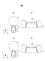
- FIG. 4 is a plan view showing an example of a contact surface after wear in a pile construction jig to which the present invention is applied
- FIG. 4D is an enlarged view of a 6D broken line frame in FIG.
- A) is a top view which shows an example of the contact surface before wear in the prior art
- B) is an enlarged view of the 7B broken line frame in (a)
- FIG. 4D is a plan view showing an example of the contact surface of FIG. 4, and FIG.
- Pile construction jig 2 to which the present invention is applied is arranged in casing tube rotating device 10 provided in tubing device 1 as shown in FIG.
- the pile construction jig 2 to which the present invention is applied is for gripping a pile 8.
- the pile construction jig 2 to which the present invention is applied is formed in a ring shape, and the pile 8 can be inserted into the center.
- the pile construction jig 2 to which the present invention is applied is used, for example, for a pile 8 having a diameter of about 400 ⁇ to 1600 ⁇ , and uniformly applies a supporting pressure for gripping the pile 8 regardless of the diameter of the pile 8. be able to.
- the pile construction jig 2 to which the present invention is applied is used for a pile 8 having a wing portion 81 projecting in a direction X perpendicular to a pile axis, and is, for example, 0.1 to 1.0 times the pile diameter. It may be used for a pile 8 having a wing portion 81 projecting from the pile 8 in the direction X orthogonal to the pile axis.
- the tubing device 1 is for press-fitting the pile 8 into the ground 9 while rotating it.
- the tubing device 1 is provided on a base frame 5 fixed to the ground 9.
- the tubing device 1 includes a casing tube rotating device 10, a cylinder 30, an upper sub chuck 32, and a lower sub chuck 33.
- the cylinder 30 is attached to the support 6 erected on the base frame 5.
- the cylinder 30 has a base 31, and controls the elevation of the casing tube rotating device 10 in the pile axis direction Y and the rotation in the pile circumferential direction W via the base 31.
- the upper sub-chuck 32 and the lower sub-chuck 33 are attached to the column 6.
- the upper sub chuck 32 is provided above the casing tube rotating device 10.
- the lower sub chuck 33 is provided below the casing tube rotating device 10.
- the upper sub-chuck 32 and the lower sub-chuck 33 hold the pile 8.
- the casing tube rotating device 10 is supported by the base 31.
- the casing tube rotating device 10 includes a horizontal lower plate 11, a horizontal upper plate 12, a lifting cylinder 13, a connecting plate 14, a rotating body 15, and a support 16.
- the horizontal lower plate 11 is supported by the base 31 via a bearing or the like.
- the horizontal upper plate 12 is disposed above the horizontal lower plate 11, and is supported by the connecting plate 14 via a bearing or the like.
- the shape of the horizontal lower plate 11 and the horizontal upper plate 12 is a ring shape.
- the lifting cylinder 13 is provided on the base 31.
- the lifting cylinder 13 controls the lifting and lowering of the horizontal upper plate 12 in the pile axial direction Y and the rotation of the pile circumferential direction W via the connecting plate 14.
- the connecting plate 14 is provided on the lifting cylinder 13 and supports the horizontal upper plate 12.
- the rotator 15 is provided on the horizontal lower plate 11.
- the rotating body 15 is formed in a ring shape, and is formed in a tapered shape whose diameter gradually increases as the upper inner periphery goes upward.
- a plurality of supports 16 are provided, and each of the supports 16 is suspended from the horizontal upper plate 12.
- the plurality of supports 16 are arranged along the pile circumferential direction W.
- Each support 16 is formed in a wedge shape having an inclined portion, and is provided such that the inclined portion is in contact with the inner periphery of the rotating body 15.
- the pile construction jig 2 to which the present invention is applied is attached to a surface of the plurality of supports 16 facing the pile 8.
- the pile construction jig 2 to which the present invention is applied is attached to a plurality of supports 16 using, for example, bolts and nuts.
- the pile 8 when the plurality of supports 16 are moved to the lower side in the pile axis direction Y using the lifting cylinder 13, the size of the diameter surrounded by each support 16 is reduced. At this time, the force acting from the outer peripheral side to the central side on the pile construction jig 2 to which the present invention is applied increases. Therefore, when the pile 8 is inserted into the tubing device 1, the pile 8 can be gripped by the pile construction jig 2 to which the present invention is applied.
- the pile construction jig 2 to which the present invention is applied includes, for example, a spiral collar 20 having a connecting portion 21 and a grip portion 22 as shown in FIG.
- the spiral collar 20 grips the pile 8 via the gripping portion 22.
- the spiral collar 20 is formed in a ring shape.
- the connecting portion 21 extends in the pile axis direction Y and is connected to the support 16.
- the grip portion 22 is joined to the connection portion 21 and extends in the pile axis orthogonal direction X.
- the weight of the connection part 21 is at least 1.05 times the weight of the grip part 22.
- the tip surface of the grip portion 22 is easily inclined in the center direction of the pile axis, and it is difficult to keep the tip surface parallel to the pile axis direction Y. For this reason, when the grip portion 22 is pushed out to the pile 8, it is difficult to uniformly apply the supporting force for gripping the pile 8.
- the connecting portion 21 and the gripping portion 22 are formed with an inner diameter, an outer diameter, and a length in the pile axial direction Y according to the diameter of the pile 8 to be gripped.
- the diameter of the pile 8 is 800 ⁇
- the diameter is about 1980 ⁇
- the inner diameter of the connection part 21 and the outer diameter of the grip part 22 are about 1600 ⁇
- the length of the connection part 21 in the pile axis direction Y is about 850mm.
- connection part 21 and the grip part 22 are divided into two or more along the pile circumferential direction W.
- the number of divisions of the connection part 21 and the grip part 22 is set according to the diameter of the pile 8 to be gripped. For example, when the diameter of the pile 8 is 800 ⁇ , the eight parts shown in FIG. 2 (the connection parts 21a to 21h, the grip part 22a To 22h).
- the set of the divided connecting part 21 and the holding part 22 is formed with an equal size, respectively, and is arranged separately from each other.
- the grip part 22 is further divided into two or more along the pile axis direction Y, as shown in FIG.
- the number of divisions of the grip portion 22 is set according to the diameter of the pile 8 to be gripped. For example, when the diameter of the pile 8 is 800 ⁇ , four (divided portions 22aa to 22ad) shown in FIG. It is divided into three (parts 22ca to 22cc) shown in b).
- the divided gripping portions 22 are formed to have the same size, and are separately arranged with the groove 25 interposed therebetween.
- the total area of the grip portion 22 overlapping the pile 8 is preferably 1/30 to 2/3 times the total area of the connection portion 21 overlapping the pile 8. .
- the force for pushing the pile 8 can be evenly distributed to each of the divided portions 22aa to 22ad and 22ca to 22cc of the gripping portions 22a and 22c.
- the area S2a of the grip portion 22a overlapping the pile 8 shown in FIG. 3A is a value obtained by multiplying the sum of the heights h2aa to h2ad in the pile axis direction Y by the width in the pile circumferential direction W.
- the area S1a of the overlapping connecting portion 21a is a value obtained by multiplying the height h1a in the pile axis direction Y by the width in the pile circumferential direction W.
- the area S2c of the grip portion 22c overlapping the pile 8 shown in FIG. 3B is a value obtained by multiplying the sum of the heights h2ca to h2cc in the pile axis direction Y by the width in the pile circumferential direction W.
- the force for pushing the pile 8 is evenly distributed. Can be dispersed.
- the spiral collar 20 has, for example, a plurality of grooves 25.
- the groove 25 is for rotating the wing 81.
- the groove portion 25 is formed between a pair of divided portions (for example, 22aa, 22ab, etc.) divided along the pile axis direction Y.
- the length (for example, lengths L22a and L22c in FIG. 3) of the grip portion 22 in the pile axis orthogonal direction X is longer than the wing portion 81. Therefore, when the wing portion 81 is turned, it can be performed in the groove 25, and the wing portion 81 does not contact the connecting portion 21.
- the pile 8 can be driven into the ground 9 by turning the pile 8 in the direction of the arrow shown in FIGS. 1 and 2. At this time, for example, as shown by an arrow in FIG. 4, by passing the wings 81 through the plurality of grooves 25, the pile 8 can be inserted without contacting the spiral collar 20.
- the wings 81 can be easily turned.
- the helical groove 25 can be easily formed by dividing each of the gripping portions 22 so as to be inclined with respect to the pile circumferential direction W.
- the uppermost groove 25 i provided in the pile axis direction Y is for calling the wing 81.
- the intake groove 25i is formed, for example, between a pair of divided portions 22ga and 22gb obtained by dividing the grip portion 22g.
- the inlet groove 25i is arranged in the pile axis direction Y with respect to another groove 25 adjacent along the pile circumferential direction W (in FIG. 4, the groove 25 provided at the top in the pile axis direction Y at the connection portion 21f). It is formed stepwise.
- the lowest delivery groove 25e in the pile axis direction Y is for sending out the swirled wing 81 from the intake groove 25i via the other plurality of grooves 25.
- the delivery groove 25e is formed, for example, between a pair of divided portions 22bc and 22bd obtained by dividing the grip portion 22b.
- the delivery groove 25e is stepped in the pile axis direction Y with respect to another groove 25 (the groove 25 between the divided portions 22cb and 22cc in FIG. 4) adjacent along the pile circumferential direction W. It is formed.
- the grip portion 22 is configured by dividing the distal end surface 23 and a pair of contact portions having contact surfaces 24 a and 24 b that contact the pile 8 into divided portions (for example, as shown in FIG. 3). It is provided for each of the divisions 22aa to 22ad and 22ca to 22cc).
- the distal end surface 23 has a planar shape that faces the outer surface of the pile 8 and is bent at a bent portion 23c extending in the pile axis direction Y.
- the distal end surface 23 is bent in a direction with the bent portion 23c inside, and is divided into two regions having the bent portion 23c as one common side.
- the shapes of the two regions are not particularly limited. For example, it can be a square shape.
- the arrangement of the contact surface 24 can be easily realized.
- the distal end surface is formed in an arc shape, it is necessary to process the contact surface in an arc shape or to form a groove in the distal end surface, so that the contact surface cannot be easily arranged.
- the planar distal end surface 23 there is no need to process the contact surface 24 or form a groove in the distal end surface 23, and the contact surface 24 can be easily arranged.
- the contact surface 24 has a planar shape and is arranged in a pair on the distal end surface 23 with the bent portion 23c interposed therebetween.
- the pair of contact surfaces 24a and 24b are arranged apart from each other, and are formed, for example, in a square shape having the same area. Therefore, the contact area between the pair of contact surfaces 24a and 24b that contact the pile 8 can be equalized, and the force acting on the pile 8 can be equalized.
- the contact surface 24 may have a hole 24h as shown in, for example, FIG. 5B and FIG. 5C, or may have an uneven portion 24s on the surface of the contact surface 24, for example.
- the hole 24h is for inserting a fixing member such as a bolt when fixing the contact surface 24 to the distal end surface 23.
- the number and position of the holes 24h are arbitrary.
- the uneven portion 24s is for increasing the frictional force when gripping the pile 8, for example, and is formed in a plurality of grooves or saw teeth.
- the contact surface 24 may be movably attached to the distal end surface 23.
- movably attach means, for example, attaching rotatably around a rotation axis parallel to the pile axis direction, or attaching a contact surface to a tip end surface with a ball joint or the like.
- a contact surface 123 formed in an arc shape may be used.
- the contact area between the contact surface 123 and the pile 8 changes significantly. This makes it difficult to maintain a state in which the support force for gripping the pile 8 acts uniformly before and after the contact surface 123 is worn.
- the weight of the connection part 21 is 1.05 times or more the weight of the grip part 22.
- the front end surface 23 of the grip portion 22 facing the outer surface of the pile 8 can be easily kept parallel to the pile axis direction Y.
- the area of the grip portion 22 overlapping the pile 8 is 1/30 times the area of the connection portion 21 overlapping the pile 8 when viewed from the pile axis orthogonal direction X. It is not less than 2/3 times. For this reason, the force for pushing the pile 8 can be evenly distributed to each of the divided portions of the grip portion 22. Thereby, when the grip portion 22 is pushed out to the pile 8, it is possible to uniformly apply the supporting force for gripping the pile 8 and improve the frictional force for gripping the pile 8.
- the pair of contact surfaces 24 are disposed on the distal end surface 23 with the bent portion 23c interposed therebetween. Therefore, a change in the contact area between the contact surface 24 and the pile 8 due to the wear of the contact surface 24 can be suppressed as compared with the case where the contact surface 24 or the distal end surface 23 is formed in an arc shape. Thereby, even when a part of the contact surface 24 is worn, it is possible to maintain a state in which the supporting force for gripping the pile 8 acts uniformly.
- the length of the grip portion 22 in the pile axis orthogonal direction X is longer than the length of the wing portion 81, and the spiral collar 20 has the plurality of groove portions 25. . Therefore, regardless of the size of the wing portion 81, the pile 8 can be inserted through the spiral collar 20 in a state where the spiral collar 20 is disposed in the casing tube rotating device 10. This makes it possible to simplify the work in pile construction.
- Tubing device 10 Casing tube rotating device 11: Horizontal lower plate 12: Horizontal upper plate 13: Lifting cylinder 14: Connecting plate 15: Rotating body 16: Support body 2: Pile construction jig 20: Spiral collar 21: Connection 22: gripping portion 23: tip surface 23c: bent portion 24: contact surface 24h: hole 24s: uneven portion 25: groove portion 25e: delivery groove portion 25i: import groove portion 30: cylinder 31: base portion 32: upper sub chuck 33: lower sub chuck. 5: Base frame 6: Post 8: Pile 81: Wing 9: Ground 123: Contact surface W: Pile circumferential direction X: Pile axis orthogonal direction Y: Pile axis direction
Landscapes
- Engineering & Computer Science (AREA)
- Life Sciences & Earth Sciences (AREA)
- General Life Sciences & Earth Sciences (AREA)
- Mining & Mineral Resources (AREA)
- Paleontology (AREA)
- Civil Engineering (AREA)
- General Engineering & Computer Science (AREA)
- Structural Engineering (AREA)
- Placing Or Removing Of Piles Or Sheet Piles, Or Accessories Thereof (AREA)
- Piles And Underground Anchors (AREA)
Abstract
本発明は、杭を把持するための支圧力を均等に作用させることを可能とするスパイラルカラーを備える杭施工治具に関し、スパイラルカラーはケーシングチューブ回転装置に接続される接続部と、杭を把持する把持部を有し、接続部の重量は、把持部の重量の1.05倍以上である。また、接続部及び把持部は、杭円周方向に沿って2つ以上に分割され、把持部は、杭軸方向に沿って2つ以上の分割部に分割され、分割部は各々、杭の外面と対向し、杭軸方向に延在する屈曲部を境に屈曲した平面状を有する先端面と、屈曲部を挟んで先端面に配置され、平面状を有する一対の接触面とを備える。
Description
本発明は、ケーシングチューブ回転装置内に配置され、杭軸直交方向に張り出した羽部を有する杭を把持するための杭施工治具に関する。
従来、杭軸直交方向に張り出した羽部を有する杭(回転杭)を把持するためのケーシングチューブ回転装置について、例えば特許文献1~5のようなチュービング装置等が提案されている。
特許文献1では、チャックカラーの内周面に、回転杭の螺旋状の掘削羽根を通過させる螺旋状の凹溝を形成したチュービング装置が開示されている。
特許文献2では、チャックシリンダを操作して、複数のチャックカラー間の内径を回転杭の胴体の径よりもやや大径にし、回転杭をクレーンで吊り上げて掘削羽根を凹溝に臨ませた後通過させてチャックカラーの下方に位置させ、チャックシリンダを操作して、回転杭の胴体を複数のチャックカラーの内周面で把持し、ケーシングチューブ回転装置を回転させることにより、回転杭を建て込む方法が開示されている。
特許文献3では、チュービング装置のケーシングチューブ挿通孔に設けたチャックカラーの内周面にチャックプレートを着脱可能に設けたチュービング装置において、チャックプレートは取付座を介してチャックカラーに取り付けられ、取付座は取付座本体の表面側にチャックプレートの上下各端面に当接する一対の端面当接突部と、チャックプレートの両側面の上下方向中央部に当接する一対の側面当接突部とを備え、チャックカラーの内周面には上下両端が開口した状態の取付座嵌着溝が形成されているチュービング装置について開示されている。
特許文献4では、チュービング装置のチャックカラーの内周面に設けた取り外し部材装着凹部に取り外し部材を装着し、チャックプレート装着凹部にチャックプレートを装着し、取り外し部材に設けた雌ねじ孔に取り外し用ボルトを螺合し、取り外し用ボルトの先端が取り外し部材装着凹部の底面に当接する反作用で取り外し部材及びチャックプレートを各装着凹部から取り外すチュービング装置について開示されている。
特許文献5には、施工場所が海底地盤あるいは湖底地盤の場合、さらに、陸上あるいは海底等において地盤表面が斜めに傾斜する場合など、不安定な場所においても杭芯が施工装置の芯からずれるのを防止しつつ回転圧入杭を地盤に回転圧入することができる回転圧入杭の施工装置として、フレームまたは昇降機構に、回転圧入杭を着脱可能に把持させる上部サブチャックと下部サブチャックを、メインチャックの上側と下側に位置するように取り付けた回転圧入杭施工装置が開示されている。
ここで、ケーシングチューブ回転装置内に配置される杭施工治具は、杭を把持するために用いられる。このため、杭施工治具の大きさは、杭の杭径や羽部の大きさに比例し、杭の杭径や羽部の拡大に伴い、杭施工治具を大きく形成する必要が生じる。しかしながら、杭施工治具を大きくした場合、杭を把持するための支圧力が、杭軸方向又は杭軸直交方向において不均等に作用し易くなるという課題が挙げられる。
すなわち、杭施工治具の重さのバランスによって、装置のガタなどにより、杭施工治具が傾くことが有り、これにより、一部のスパイラルカラーのみが杭に当たり、杭を把持するための支圧力が不均等となる場合がある。さらに、その結果、一部のスパイラルカラーのみ摩耗するという問題がある。これにより、例えば偏圧により杭の一部が凹んだり、杭が破損したりする等の不具合を発生させる恐れがある。
この点、特許文献1~5では、上述したような杭施工治具を大きくした場合についての弊害や、その対策について記載も示唆もされていない。このため、特許文献1~5に記載された開示技術では、杭を把持するための支圧力を均等に作用させることが難しい。
そこで、本発明は、上述した問題点に鑑みて案出されたものであって、その目的とするところは、杭を把持するための支圧力を均等に作用させ、杭が滑ったり圧壊したりすることを防止することを可能とする杭施工治具を提供することにある。
さらに、本発明では、施工時に土等がスパイラルカラーに付着することにより、杭を把持するための支圧力を均等に作用させられなくなることも、あわせて防止することを可能とすることを課題とする。
本発明は上記の課題に鑑みなされたものであって、その要旨は以下のとおりである。
(1)ケーシングチューブ回転装置内に配置され、杭軸直交方向に張り出した羽部を有する杭を把持するためのスパイラルカラーを備える杭施工治具であって、前記スパイラルカラーは、杭軸方向に延在して前記ケーシングチューブ回転装置に接続される接続部と、前記接続部に接合されて杭軸直交方向に延在する把持部とを有し、前記スパイラルカラーは、前記把持部を介して前記杭を把持し、前記接続部の重量は、前記把持部の重量の1.05倍以上であり、前記接続部及び前記把持部は、杭円周方向に沿って2つ以上に分割され、前記把持部は、杭軸方向に沿って2つ以上の分割部に分割され、前記分割部は各々、前記杭の外面と対向し、杭軸方向に延在する屈曲部を境に角度をつけた2つの領域に分けられる先端面と、前記屈曲部を挟んで前記先端面に配置された平面状の一対の接触面とを備えることを特徴とする杭施工治具。
(2)杭軸直交方向から見て、前記杭と重なる前記把持部の面積は、前記杭と重なる前記接続部の面積の1/30倍以上2/3倍以下であることを特徴とする前記(1)の杭施工治具。
(3)前記把持部の杭軸直交方向の長さは、杭径の0.1倍以上1.0倍以下の長さで、かつ、前記杭から杭軸直交方向に張り出した前記羽部の長さよりも長く、前記スパイラルカラーは、杭軸方向に沿って分割された一対の前記分割部の間に、前記羽部を旋回させるための溝部を複数有し、複数の前記溝部のうち、杭軸方向の最も上に設けられ、杭円周方向に沿って隣接する他の前記溝部に対して杭軸方向へ段違いにして形成される呼び込み溝部は、前記羽部を呼び込むためのものであり、複数の前記溝部のうち、杭軸方向の最も下に設けられ、杭円周方向に沿って隣接するさらに他の前記溝部に対して杭軸方向へ段違いにして形成される送り出し溝部は、前記呼び込み溝部から他の複数の前記溝部を経由して旋回した前記羽部を送り出すためのものであることを特徴とする前記(1)又は(2)の杭施工治具。
(4)前記接触面が表面に凹凸部を備えることを特徴とする前記(1)~(3)のいずれかの杭施工治具。
(5)前記(1)~(4)のいずれかの杭施工治具を備えるチュービング装置。
本発明によれば、杭の外面に対向する把持部の先端面を、杭軸方向に対して平行に保ち易くすることができ、杭施工治具の大きさに関わらず、把持部を杭に押し出した際、杭を把持するための支圧力を均等に作用させることが可能となる。さらに、施工時に土等が付着することにより、杭を把持するための支圧力が均等に作用しなくなることを防止することが可能となる。
以下、本発明を適用した杭施工治具を実施するための形態について、図面を参照しながら詳細に説明する。
本発明を適用した杭施工治具2は、図1に示すように、チュービング装置1が備えるケーシングチューブ回転装置10内に配置される。本発明を適用した杭施工治具2は、杭8を把持するためのものである。本発明を適用した杭施工治具2は、リング状に形成され、中心に杭8を挿通させることができる。
本発明を適用した杭施工治具2は、例えば径が400φ~1600φ程度の杭8に対して用いられ、杭8の径に関わらず、杭8を把持するための支圧力を均等に作用させることができる。なお、本発明を適用した杭施工治具2は、杭軸直交方向Xに張り出した羽部81を有する杭8に対して用いられ、例えば杭径の0.1倍以上1.0倍以下の長さで杭8から杭軸直交方向Xに張り出した羽部81を有する杭8に対して用いられてもよい。
チュービング装置1は、杭8を地盤9に回転させながら圧入するためのものである。チュービング装置1は、地盤9に固定されたベースフレーム5上に設けられる。チュービング装置1は、ケーシングチューブ回転装置10と、シリンダ30と、上部サブチャック32と、下部サブチャック33とを有する。
シリンダ30は、ベースフレーム5上に立設された支柱6に取り付けられる。シリンダ30は、基部31を有し、基部31を介してケーシングチューブ回転装置10における杭軸方向Yの昇降、及び杭円周方向Wの回転を制御するものである。
上部サブチャック32及び下部サブチャック33は、支柱6に取り付けられる。上部サブチャック32は、ケーシングチューブ回転装置10よりも上に設けられる。下部サブチャック33は、ケーシングチューブ回転装置10よりも下に設けられる。上部サブチャック32及び下部サブチャック33は、杭8を把持するものである。
ケーシングチューブ回転装置10は、基部31に支持される。ケーシングチューブ回転装置10は、水平下板11と、水平上板12と、昇降シリンダ13と、連結板14と、回転体15と、支持体16とを有する。
水平下板11は、ベアリング等を介して基部31に支持される。水平上板12は、水平下板11の上方に配置され、ベアリング等を介して連結板14に支持される。水平下板11及び水平上板12の形状は、リング状である。
昇降シリンダ13は、基部31上に設けられる。昇降シリンダ13は、連結板14を介して水平上板12における杭軸方向Yの昇降、及び杭円周方向Wの回転を制御する。連結板14は、昇降シリンダ13上に設けられ、水平上板12を支持する。
回転体15は、水平下板11上に設けられる。回転体15は、リング状に形成され、上部内周が上方に向かうに従い漸次拡径するテーパ状に形成される。支持体16は、複数設けられ、それぞれ水平上板12に吊持される。複数の支持体16は、杭円周方向Wに沿って配置される。各支持体16は、傾斜部を有する楔状に形成され、傾斜部が回転体15の内周に当接するように設けられる。
本発明を適用した杭施工治具2は、複数の支持体16における杭8と対向する面に取り付けられる。本発明を適用した杭施工治具2は、例えばボルト及びナットを用いて、複数の支持体16に取り付けられる。
例えば、昇降シリンダ13を用いて、複数の支持体16を杭軸方向Yの下側に移動させたとき、各支持体16に囲まれる径の大きさが縮小する。このとき、本発明を適用した杭施工治具2に対して、外周側から中心側に作用する力が大きくなる。このため、チュービング装置1に杭8が挿通されている場合、本発明を適用した杭施工治具2によって杭8を把持することができる。
また、昇降シリンダ13を用いて、複数の支持体16を杭軸方向Yの上側に移動させたとき、各支持体16に囲まれる径の大きさが拡大する。このとき、本発明を適用した杭施工治具2に対して、外周側から中心側に作用する力が弱くなる。このため、チュービング装置1に杭8が挿通されている場合、本発明を適用した杭施工治具2によって杭8を把持した状態を解除することができる。
本発明を適用した杭施工治具2は、例えば図2に示すように、接続部21と、把持部22とを有するスパイラルカラー20を備える。スパイラルカラー20は、把持部22を介して杭8を把持するものである。スパイラルカラー20は、リング状に形成される。
接続部21は、杭軸方向Yに延在し、支持体16に接続される。把持部22は、接続部21に接合されて杭軸直交方向Xに延在する。接続部21の重量は、把持部22の重量の1.05倍以上である。例えば接続部21の重量が把持部22の重量の1.05倍未満の場合、把持部22の先端面が杭軸中心方向に傾きやすくなり、杭軸方向Yに対して平行に保ち難くなる。このため、把持部22を杭8に押し出した際、杭8を把持するための支圧力を均等に作用させることが困難となる。
接続部21及び把持部22は、把持する杭8の径に応じて内径、外径、及び杭軸方向Yの長さが形成され、例えば杭8の径が800φの場合、接続部21の外径が1980φ程度、接続部21の内径及び把持部22の外径が1600φ程度、並びに、接続部21における杭軸方向Yの長さが850mm程度に形成される。
接続部21及び把持部22は、杭円周方向Wに沿って2つ以上に分割される。接続部21及び把持部22は、把持する杭8の径に応じて分割数が設定され、例えば杭8の径が800φの場合、図2に示す8つ(接続部21a~21h、把持部22a~22h)に分割される。なお、分割された接続部21及び把持部22の組は、それぞれ均等の大きさで形成され、それぞれ離間して配置される。
把持部22は、さらに、図3に示すように、杭軸方向Yに沿って2つ以上に分割される。把持部22は、把持する杭8の径に応じて分割数が設定され、例えば杭8の径が800φの場合、図3(a)に示す4つ(分割部22aa~22ad)又は図3(b)に示す3つ(分割部22ca~22cc)に分割される。なお、分割された把持部22は、それぞれ均等の大きさで形成され、それぞれ溝部25を挟んで離間して配置される。
このとき、杭軸直交方向Xから見て、杭8と重なる把持部22の総面積は、杭8と重なる接続部21の総面積の1/30倍以上2/3倍以下であることが好ましい。このため、例えば把持部22a、22cの分割された各分割部22aa~22ad、22ca~22ccに対して、杭8を押す力を均等に分散させることができる。
杭8と重なる把持部22の面積が、杭8と重なる接続部21の面積の1/30倍以上の場合、各把持部22に作用する負荷が大きくならず、好ましい。また、例えば杭8と重なる把持部22の面積が、杭8と重なる接続部21の面積の2/3倍以下の場合、各把持部22に作用する力のバラつきがあまり大きくならず、杭8における径が大きくなっても、杭8を把持するための支圧力を均等に作用させやすくなり、好ましい。加えて、杭8に作用する支圧力が不均等になりにくいことで、杭8が損傷するのを防止することができる。さらに、杭8を旋回させ地盤9に打設する際に、羽部81を旋回させて把持部22の周辺を通過させやすくなり、好ましい。
例えば図3(a)に示す杭8と重なる把持部22aの面積S2aは、杭軸方向Yの高さh2aa~h2adの合計に杭円周方向Wの幅を掛けた値であり、杭8と重なる接続部21aの面積S1aは、杭軸方向Yの高さh1aに杭円周方向Wの幅を掛けた値である。また、例えば図3(b)に示す杭8と重なる把持部22cの面積S2cは、杭軸方向Yの高さh2ca~h2ccの合計に杭円周方向Wの幅を掛けた値であり、杭8と重なる接続部21cの面積S1cは、杭軸方向Yの高さh1cに杭円周方向Wの幅を掛けた値である。このとき、面積S2aが面積S1aの1/30倍以上2/3倍以下、及び面積S2cが面積S1cの1/30倍以上2/3倍以下とすることで、杭8を押す力を均等に分散させることができる。
スパイラルカラー20は、例えば複数の溝部25を有する。溝部25は、羽部81を旋回させるためのものである。溝部25は、杭軸方向Yに沿って分割された一対の分割部(例えば22aa、22ab等)の間に形成される。なお、把持部22における杭軸直交方向Xの長さ(例えば図3の長さL22a、L22c)は、羽部81よりも長い。このため、羽部81を旋回させるとき、溝部25内で行うことができ、接続部21に羽部81が接触しない。
例えば、図1及び図2に示す矢印の方向に杭8を旋回させることで、杭8を地盤9に打設することができる。このとき、例えば図4の矢印に示すように、複数の溝部25に羽部81を通過させることで、杭8をスパイラルカラー20に接触することなく挿通させることができる。
特に、複数の溝部25は、杭円周方向Wに沿って螺旋状に形成されることで、羽部81を容易に旋回させることができる。このとき、例えば各把持部22が、杭円周方向Wに対して傾斜して分割されることで、螺旋状の溝部25を容易に形成することができる。
複数の溝部25のうち、杭軸方向Yの最も上に設けられた呼び込み溝部25iは、羽部81を呼び込むためのものである。呼び込み溝部25iは、例えば把持部22gを分割した一対の分割部22ga、22gbの間に形成される。呼び込み溝部25iは、杭円周方向Wに沿って隣接する他の溝部25(図4では、接続部21fにおける杭軸方向Yの最も上に設けられた溝部25)に対して杭軸方向Yへ段違いにして形成される。
複数の溝部25のうち、杭軸方向Yの最も下に設けられた送り出し溝部25eは、呼び込み溝部25iから他の複数の溝部25を経由して旋回した羽部81を送り出すためのものである。送り出し溝部25eは、例えば把持部22bを分割した一対の分割部22bc、22bdの間に形成される。送り出し溝部25eは、杭円周方向Wに沿って隣接するさらに他の溝部25(図4では、分割部22cbと分割部22ccとの間の溝部25)に対して杭軸方向Yへ段違いにして形成される。呼び込み溝部25i及び送り出し溝部25eを形成することで、杭8をスパイラルカラー20に挿通するときの旋回位置が明確となり、複数の溝部25に羽部81を容易に通過させることができる。
把持部22は、例えば図5に示すように、先端面23と、一対の、杭8に接触する接触面24a、24bを有する接触部とを、分割された分割部(例えば図3に示した分割部22aa~22ad、22ca~22cc)毎に有する。
先端面23は、例えば図5(a)に示すように、杭8の外面と対向し、杭軸方向Yに延在する屈曲部23cを境に屈曲した平面状を有する。先端面23は、屈曲部23cを内側とする方向に屈曲され、屈曲部23cを共通の1辺とした2つの領域に分けられる。2つの領域の形状は特に限定されない。たとえば、四角形状とすることができる。
先端面23が平面状を有することで、接触面24の配置を容易に実現することができる。例えば先端面が円弧状に形成されている場合、接触面を円弧状に加工する必要や、先端面に溝を形成する必要が生じ、容易に接触面を配置できないという事情がある。これに対し、平面状の先端面23では、接触面24の加工や先端面23に溝を形成する必要がなく、接触面24の配置を容易に行うことができる。
また、先端面23を屈曲部23cを境に角度をつけた2つの領域に分けることによって、施工時に土が付着しにくくなり、また、土が付着した場合であっても、屈曲部23c周辺に隙間ができるため、そこを起点として付着した土が落ちやすくなるので、付着した土に邪魔されることなく、杭を均等に把持することができるようになり、あわせて、長時間の施工が可能となる。
接触面24は、平面状を有し、屈曲部23cを挟んで先端面23に一対配置される。一対の接触面24a、24bは、互いに離間して配置され、例えば等しい面積を有する四角形状に形成される。このため、杭8に接触する一対の接触面24a、24bにおける接触面積を等しくすることができ、杭8に対して作用する力を均等にすることができる。
接触面24は、例えば図5(b)及び図5(c)に示すように、孔24hを有するほか、例えば接触面24の表面に凹凸部24sを有してもよい。孔24hは、先端面23に接触面24を固定させるときに、ボルト等の固定部材を挿通するためのものである。孔24hの数及び位置は任意である。凹凸部24sは、例えば杭8を把持するときの摩擦力を高めるためのものであり、複数の溝状や鋸歯状に形成される。
また、接触面24は、先端面23に可動に取り付けられてもよい。ここで「可動に取り付ける」とは、たとえば、杭軸方向に平行な回転軸を中心として回転可能に取り付けることや、接触面をボール継手などで先端面に取り付けることである。
本発明を適用した杭施工治具2では、例えば図6(a)及び図6(b)に示すように、杭8を把持するとき、複数の平面状の接触面24(図6(b)では接触面24a、24b)が杭8に接触する。このため、接触面24が摩耗した場合においても、例えば図6(c)及び図6(d)に示すように、接触面24と杭8との接触面積の変化を抑制することができる。これにより、接触面24の摩耗前後において、杭8を把持するための支持力を均等に作用する状態を維持することが可能となる。
これに対し、例えば図7(a)及び図7(b)に示すように、円弧状に形成された接触面123が用いられることがある。このとき、接触面123が摩耗した場合において、例えば図7(c)及び図7(d)に示すように、接触面123と杭8との接触面積が大幅に変化する。これにより、接触面123の摩耗前後において、杭8を把持するための支持力を均等に作用する状態を維持することが困難となる。
本発明を適用した杭施工治具2によれば、接続部21の重量は、把持部22の重量の1.05倍以上である。このため、杭8の外面に対向する把持部22の先端面23を、杭軸方向Yに対して平行に保ち易くすることができる。これにより、杭施工治具2の大きさに関わらず、把持部22を杭8に押し出した際、杭8を把持するための支圧力を均等に作用させることが可能となる。
また、本発明を適用した杭施工治具2によれば、杭軸直交方向Xから見て、杭8と重なる把持部22の面積は、杭8と重なる接続部21の面積の1/30倍以上2/3倍以下である。このため、把持部22の分割された各分割部に対して、杭8を押す力を均等に分散させることができる。これにより、把持部22を杭8に押し出した際、杭8を把持するための支圧力を均等に作用させるとともに、杭8を把持するための摩擦力を向上させることが可能となる。
また、本発明を適用した杭施工治具2によれば、一対の接触面24は、屈曲部23cを挟んで先端面23に配置される。このため、接触面24又は先端面23が円弧状に形成される場合に比べて、接触面24の摩耗に伴う接触面24と杭8との接触面積の変化を抑制することができる。これにより、接触面24の一部が摩耗した場合においても、杭8を把持するための支圧力を均等に作用する状態を維持することが可能となる。
また、本発明を適用した杭施工治具2によれば、把持部22における杭軸直交方向Xの長さは、羽部81の長さよりも長く、スパイラルカラー20は、複数の溝部25を有する。このため、羽部81の大きさに関わらず、スパイラルカラー20をケーシングチューブ回転装置10内に配置した状態で、杭8をスパイラルカラー20に挿通させることができる。これにより、杭施工における作業の簡略化を図ることが可能となる。
以上、本発明の実施形態の例について詳細に説明したが、上述した実施形態は、何れも本発明を実施するにあたっての具体化の例を示したものに過ぎず、これらによって本発明の技術的範囲が限定的に解釈されてはならない。
1 :チュービング装置
10 :ケーシングチューブ回転装置
11 :水平下板
12 :水平上板
13 :昇降シリンダ
14 :連結板
15 :回転体
16 :支持体
2 :杭施工治具
20 :スパイラルカラー
21 :接続部
22 :把持部
23 :先端面
23c :屈曲部
24 :接触面
24h :孔
24s :凹凸部
25 :溝部
25e :送り出し溝部
25i :呼び込み溝部
30 :シリンダ
31 :基部
32 :上部サブチャック
33 :下部サブチャック
5 :ベースフレーム
6 :支柱
8 :杭
81 :羽部
9 :地盤
123 :接触面
W :杭円周方向
X :杭軸直交方向
Y :杭軸方向
10 :ケーシングチューブ回転装置
11 :水平下板
12 :水平上板
13 :昇降シリンダ
14 :連結板
15 :回転体
16 :支持体
2 :杭施工治具
20 :スパイラルカラー
21 :接続部
22 :把持部
23 :先端面
23c :屈曲部
24 :接触面
24h :孔
24s :凹凸部
25 :溝部
25e :送り出し溝部
25i :呼び込み溝部
30 :シリンダ
31 :基部
32 :上部サブチャック
33 :下部サブチャック
5 :ベースフレーム
6 :支柱
8 :杭
81 :羽部
9 :地盤
123 :接触面
W :杭円周方向
X :杭軸直交方向
Y :杭軸方向
Claims (5)
- ケーシングチューブ回転装置内に配置され、杭軸直交方向に張り出した羽部を有する杭を把持するためのスパイラルカラーを備える杭施工治具であって、
前記スパイラルカラーは、
杭軸方向に延在して前記ケーシングチューブ回転装置に接続される接続部と、
前記接続部に接合されて杭軸直交方向に延在する把持部
とを有し、
前記スパイラルカラーは、前記把持部を介して前記杭を把持し、
前記接続部の重量は、前記把持部の重量の1.05倍以上であり、
前記接続部及び前記把持部は、杭円周方向に沿って2つ以上に分割され、
前記把持部は、杭軸方向に沿って2つ以上の分割部に分割され、
前記分割部は各々、
前記杭の外面と対向し、杭軸方向に延在する屈曲部を境に角度をつけた2つの領域に分けられる先端面と、
前記屈曲部を挟んで前記先端面に配置された平面状の一対の接触面
とを備える
ことを特徴とする杭施工治具。 - 杭軸直交方向から見て、前記杭と重なる前記把持部の面積は、前記杭と重なる前記接続部の面積の1/30倍以上2/3倍以下であることを特徴とする請求項1記載の杭施工治具。
- 前記把持部の杭軸直交方向の長さは、杭径の0.1倍以上1.0倍以下の長さで、かつ、前記杭から杭軸直交方向に張り出した前記羽部の長さよりも長く、
前記スパイラルカラーは、杭軸方向に沿って分割された一対の前記分割部の間に、前記羽部を旋回させるための溝部を複数有し、
複数の前記溝部のうち、杭軸方向の最も上に設けられ、杭円周方向に沿って隣接する他の前記溝部に対して杭軸方向へ段違いにして形成される呼び込み溝部は、前記羽部を呼び込むためのものであり、
複数の前記溝部のうち、杭軸方向の最も下に設けられ、杭円周方向に沿って隣接するさらに他の前記溝部に対して杭軸方向へ段違いにして形成される送り出し溝部は、前記呼び込み溝部から他の複数の前記溝部を経由して旋回した前記羽部を送り出すためのものであること
を特徴とする請求項1又は2に記載の杭施工治具。 - 前記接触面が表面に凹凸部を備えることを特徴とする請求項1~3のいずれか1項に記載の杭施工治具。
- 請求項1~4のいずれか1項に記載の杭施工治具を備えるチュービング装置。
Priority Applications (3)
| Application Number | Priority Date | Filing Date | Title |
|---|---|---|---|
| JP2020545976A JP7107379B2 (ja) | 2018-09-10 | 2019-09-05 | 杭施工治具 |
| SG11202011661UA SG11202011661UA (en) | 2018-09-10 | 2019-09-05 | Jig for pile driving |
| PH12021550446A PH12021550446A1 (en) | 2018-09-10 | 2021-03-01 | Jig for pile driving |
Applications Claiming Priority (2)
| Application Number | Priority Date | Filing Date | Title |
|---|---|---|---|
| JP2018-168513 | 2018-09-10 | ||
| JP2018168513 | 2018-09-10 |
Publications (1)
| Publication Number | Publication Date |
|---|---|
| WO2020054583A1 true WO2020054583A1 (ja) | 2020-03-19 |
Family
ID=69777620
Family Applications (1)
| Application Number | Title | Priority Date | Filing Date |
|---|---|---|---|
| PCT/JP2019/035042 Ceased WO2020054583A1 (ja) | 2018-09-10 | 2019-09-05 | 杭施工治具 |
Country Status (5)
| Country | Link |
|---|---|
| JP (1) | JP7107379B2 (ja) |
| PH (1) | PH12021550446A1 (ja) |
| SG (1) | SG11202011661UA (ja) |
| TW (1) | TW202018151A (ja) |
| WO (1) | WO2020054583A1 (ja) |
Citations (2)
| Publication number | Priority date | Publication date | Assignee | Title |
|---|---|---|---|---|
| JP2001146744A (ja) * | 1999-11-22 | 2001-05-29 | Nippon Steel Corp | 回転圧入杭の施工装置と施工方法 |
| JP2013119768A (ja) * | 2011-12-09 | 2013-06-17 | Nippon Sharyo Seizo Kaisha Ltd | チュービング装置 |
Family Cites Families (4)
| Publication number | Priority date | Publication date | Assignee | Title |
|---|---|---|---|---|
| JP3484653B2 (ja) | 1999-03-02 | 2004-01-06 | 日本車輌製造株式会社 | チュービング装置 |
| JP3828460B2 (ja) | 2002-06-17 | 2006-10-04 | 日本車輌製造株式会社 | 螺旋状掘削羽根を有する回転捩じ込み杭をチュービング装置のチャック装置で把持する方法 |
| JP6027888B2 (ja) | 2012-12-28 | 2016-11-16 | 新日鉄住金エンジニアリング株式会社 | 回転圧入杭の施工装置及び施工方法 |
| JP6210702B2 (ja) | 2013-04-01 | 2017-10-11 | 日本車輌製造株式会社 | チュービング装置 |
-
2019
- 2019-09-05 WO PCT/JP2019/035042 patent/WO2020054583A1/ja not_active Ceased
- 2019-09-05 JP JP2020545976A patent/JP7107379B2/ja active Active
- 2019-09-05 SG SG11202011661UA patent/SG11202011661UA/en unknown
- 2019-09-09 TW TW108132441A patent/TW202018151A/zh unknown
-
2021
- 2021-03-01 PH PH12021550446A patent/PH12021550446A1/en unknown
Patent Citations (2)
| Publication number | Priority date | Publication date | Assignee | Title |
|---|---|---|---|---|
| JP2001146744A (ja) * | 1999-11-22 | 2001-05-29 | Nippon Steel Corp | 回転圧入杭の施工装置と施工方法 |
| JP2013119768A (ja) * | 2011-12-09 | 2013-06-17 | Nippon Sharyo Seizo Kaisha Ltd | チュービング装置 |
Also Published As
| Publication number | Publication date |
|---|---|
| TW202018151A (zh) | 2020-05-16 |
| JP7107379B2 (ja) | 2022-07-27 |
| PH12021550446A1 (en) | 2021-09-27 |
| JPWO2020054583A1 (ja) | 2021-04-30 |
| SG11202011661UA (en) | 2020-12-30 |
Similar Documents
| Publication | Publication Date | Title |
|---|---|---|
| AU2013266945B2 (en) | Device and method for handling drill string components in a drill rig and drill rig | |
| EP3442751B1 (en) | Bearing race installer/remover | |
| US7775270B1 (en) | Spider with distributed gripping dies | |
| CN210232831U (zh) | 一种顶头拆卸的扳手 | |
| WO2020054583A1 (ja) | 杭施工治具 | |
| CN212070997U (zh) | 臂架滑轮组装配工装 | |
| JP7017423B2 (ja) | 回転圧入鋼管杭の流体噴射装置及び鋼管杭の回転圧入工法 | |
| CN112252591A (zh) | 一种具有纠偏功能的钢筋骨架用连接件 | |
| JP3840179B2 (ja) | 杭把持径調整冶具および回転圧入杭の施工方法 | |
| CN203956412U (zh) | 一种用于混凝土泵车输送管的组焊定位装置 | |
| CN210364120U (zh) | 控制螺杆升降的电机用固定装置 | |
| CN104002089B (zh) | 一种用于混凝土泵车输送管的组焊定位装置 | |
| JP5321549B2 (ja) | 斜杭継ぎ用治具、その治具を用いた斜杭継ぎ方法及び構造物の製造方法 | |
| CN117657929A (zh) | 涡轮转静子吊装工具 | |
| JP2000248549A (ja) | チュービング装置 | |
| CN112640272B (zh) | 旋转电机的临时固定夹具以及使用该临时固定夹具的旋转电机的组装方法 | |
| CN210661954U (zh) | 一种转动设备中心找正微量位移调整器 | |
| EP3576912B1 (en) | Feed roller | |
| JP3568528B1 (ja) | 鋼管杭の回転装置 | |
| JP4326688B2 (ja) | 中空杭チャック装置のチャックカラー | |
| CN112012556A (zh) | 斜拉索用连接组件、斜拉索地锚及施工方法、拉索式塔筒 | |
| CN210587805U (zh) | 一种转动轴焊接用夹具 | |
| JP2003041585A (ja) | 螺旋状掘削羽根を有する回転捩じ込み杭をチュービング装置のチャック装置で把持する方法 | |
| JP2023010161A (ja) | チャック装置 | |
| CN205290682U (zh) | 一种齿轮保持架 |
Legal Events
| Date | Code | Title | Description |
|---|---|---|---|
| 121 | Ep: the epo has been informed by wipo that ep was designated in this application |
Ref document number: 19860274 Country of ref document: EP Kind code of ref document: A1 |
|
| ENP | Entry into the national phase |
Ref document number: 2020545976 Country of ref document: JP Kind code of ref document: A |
|
| NENP | Non-entry into the national phase |
Ref country code: DE |
|
| 122 | Ep: pct application non-entry in european phase |
Ref document number: 19860274 Country of ref document: EP Kind code of ref document: A1 |