WO2020054075A1 - 転写型感光性フィルム、樹脂硬化膜の形成方法及び樹脂硬化膜付センサ基板の製造方法 - Google Patents
転写型感光性フィルム、樹脂硬化膜の形成方法及び樹脂硬化膜付センサ基板の製造方法 Download PDFInfo
- Publication number
- WO2020054075A1 WO2020054075A1 PCT/JP2018/034290 JP2018034290W WO2020054075A1 WO 2020054075 A1 WO2020054075 A1 WO 2020054075A1 JP 2018034290 W JP2018034290 W JP 2018034290W WO 2020054075 A1 WO2020054075 A1 WO 2020054075A1
- Authority
- WO
- WIPO (PCT)
- Prior art keywords
- film
- photosensitive resin
- resin layer
- photosensitive
- intermediate layer
- Prior art date
- Legal status (The legal status is an assumption and is not a legal conclusion. Google has not performed a legal analysis and makes no representation as to the accuracy of the status listed.)
- Ceased
Links
- 0 *C1(c(cc(cc2)C(*)=*OC(I)=O)c2-c2ccc(*)cc12)O Chemical compound *C1(c(cc(cc2)C(*)=*OC(I)=O)c2-c2ccc(*)cc12)O 0.000 description 1
Images


Classifications
-
- G—PHYSICS
- G01—MEASURING; TESTING
- G01N—INVESTIGATING OR ANALYSING MATERIALS BY DETERMINING THEIR CHEMICAL OR PHYSICAL PROPERTIES
- G01N27/00—Investigating or analysing materials by the use of electric, electrochemical, or magnetic means
-
- G—PHYSICS
- G03—PHOTOGRAPHY; CINEMATOGRAPHY; ANALOGOUS TECHNIQUES USING WAVES OTHER THAN OPTICAL WAVES; ELECTROGRAPHY; HOLOGRAPHY
- G03F—PHOTOMECHANICAL PRODUCTION OF TEXTURED OR PATTERNED SURFACES, e.g. FOR PRINTING, FOR PROCESSING OF SEMICONDUCTOR DEVICES; MATERIALS THEREFOR; ORIGINALS THEREFOR; APPARATUS SPECIALLY ADAPTED THEREFOR
- G03F7/00—Photomechanical, e.g. photolithographic, production of textured or patterned surfaces, e.g. printing surfaces; Materials therefor, e.g. comprising photoresists; Apparatus specially adapted therefor
- G03F7/004—Photosensitive materials
Definitions
- the present invention relates to a transfer type photosensitive film, a method for forming a cured resin film, and a method for manufacturing a sensor substrate with a cured resin film.
- a capacitive touch sensor substrate As a sensor substrate used for an image display device such as a touch panel, a capacitive touch sensor substrate is known.
- a transparent electrode such as ITO and wiring such as copper or a copper / nickel alloy are provided on the touch sensor substrate, and a protective film may be provided to protect these electrodes and wiring. In this case, it is necessary to form the protective film with a material having excellent light transmittance so as not to affect the quality of the image.
- a biosensor substrate provided with a dielectrophoretic electrode is also known as a sensor substrate used in a microorganism measuring device.
- Patent Literature 1 discloses a comb-shaped electrode pattern for collecting fine particles in a liquid sample such as a microorganism by a dielectrophoresis method.
- a dielectric film for electrically insulating the liquid sample is provided on the electrode pattern. In this case, it is desirable to form the dielectric film with a material having excellent light transmittance so that adverse effects do not occur when optically observing or analyzing the collected fine particles.
- a photosensitive film having a photosensitive resin layer containing a binder polymer, a photopolymerizable compound and a photopolymerization initiator is known. According to such a photosensitive film, a resin cured film having a predetermined pattern shape can be easily formed by laminating a photosensitive resin layer on a base material, and performing exposure and development.
- a protective film or a dielectric film is provided on the above-described touch sensor substrate or biosensor substrate, it is required to make the film thinner from the viewpoint of improving sensitivity.
- the thickness of the photosensitive resin layer is reduced, there is a problem that voids (bubbles) are easily generated during lamination.
- a sensor such as a touch panel or a microorganism measuring device is provided with a delicate pattern, and a void is easily left in a concave portion thereof.
- the present invention is directed to a transfer type photosensitive film, a method of forming a cured resin film, and a method of curing a cured resin film, which can favorably form a thin resin cured film while sufficiently suppressing generation of voids even on a substrate having a step.
- An object of the present invention is to provide a method for manufacturing a sensor substrate with a film.
- the present inventors have conducted intensive studies and as a result, provided an intermediate layer containing a water-soluble polymer between the support film and the photosensitive resin layer, and the photosensitive resin layer shows a specific hydrophilicity
- the composition as described above it is possible to sufficiently suppress the occurrence of voids even when the thinned photosensitive resin layer is laminated on a stepped substrate, and to solve the problem caused by providing the intermediate layer. And found that the present invention was completed.
- the present invention has a structure in which a support film, an intermediate layer containing a water-soluble polymer, and a photosensitive resin layer are laminated in this order, the photosensitive resin layer has a thickness of 2.5 ⁇ m or less, and And a transfer-type photosensitive film having a contact angle with water of 60 to 90 ° on the surface of the cured photosensitive resin layer in contact with the intermediate layer.
- a thin resin cured film can be satisfactorily formed while sufficiently suppressing the generation of voids even on a substrate having a step.
- the transfer type photosensitive film since the transfer type photosensitive film has a combination of the intermediate layer containing the water-soluble polymer and the photosensitive resin layer showing specific hydrophilicity, the thickness of the photosensitive film is sufficiently secured during lamination. By doing so, the followability of the photosensitive resin layer to the step is improved, and after lamination, the intermediate layer is removed by development, so that only a thin resin cured film can be left.
- the intermediate layer and the photosensitive resin layer have an appropriate affinity, for example, when a protective film is provided on the side opposite to the intermediate layer of the photosensitive resin layer, when the protective film is peeled off
- the photosensitive resin layer can be prevented from peeling off with the protective film, and when wound without the protective film, the photosensitive resin layer can be prevented from peeling off to the adjacent support film side when the photosensitive film is pulled out.
- the intermediate layer may contain polyvinyl alcohol in an amount of 50% by mass or more from the viewpoint of improving followability during lamination.
- the photosensitive resin layer preferably has a total light transmittance of 85% or more in a visible light region having a wavelength of 400 to 700 nm.
- the photosensitive resin layer preferably has b * of -0.2 to 1.0 in the CIELAB color system.
- the intermediate layer preferably has a thickness of 3 to 30 ⁇ m.
- the transfer type photosensitive film of the present invention may be used for forming a protective film on a biosensor substrate.
- the transfer photosensitive film of the present invention may be used for forming a protective film on a dielectrophoretic electrode of a biosensor substrate having a dielectrophoretic electrode.
- the present invention also provides a step of laminating the transfer-type photosensitive film according to the present invention on a substrate having a step on one principal surface so that a photosensitive resin layer covers the step, Irradiating a predetermined portion of the photosensitive resin layer with light; and contacting the developing solution with the photosensitive resin layer and the intermediate layer from the side of the intermediate layer from which the support film has been removed, thereby forming a predetermined portion of the photosensitive resin layer. Removing a portion other than the portion and the intermediate layer to form a cured resin film covering the step.
- a thin resin cured film can be formed on a substrate having a step while sufficiently suppressing generation of voids.
- the transfer type photosensitive film is provided with a protective film on the side opposite to the intermediate layer of the photosensitive resin layer, the peeling of the photosensitive resin layer together with the protective film when the protective film is peeled can be suppressed, and the protection can be achieved.
- the photosensitive resin layer is wound without a film, it is possible to prevent the photosensitive resin layer from peeling to the adjacent support film side when the photosensitive film is pulled out.
- the step may be a step caused by a transparent electrode and / or wiring provided on the main surface of the base material.
- the step may be a step caused by a dielectrophoretic electrode provided on the main surface of the base material.
- the present invention also provides a transfer type photosensitive film according to the present invention on a substrate having a transparent electrode and / or wiring on one main surface, such that a photosensitive resin layer covers the transparent electrode and / or wiring. Laminating, irradiating a predetermined portion of the photosensitive resin layer on the substrate with light, and developing solution from the side of the intermediate layer from which the support film has been removed to the irradiated photosensitive resin layer and the intermediate layer. Forming a cured resin film covering the transparent electrode and / or the wiring by removing the intermediate layer other than the predetermined portion of the photosensitive resin layer by contacting the photosensitive resin layer. A manufacturing method is provided.
- the first method for manufacturing a sensor substrate with a cured resin film of the present invention it is possible to obtain a sensor substrate provided with a cured resin film having a sufficiently small number of voids as a thin film as a protective film for a transparent electrode and / or wiring. Can be.
- the present invention also provides a step of laminating a transfer type photosensitive film according to the present invention on a substrate having a dielectrophoretic electrode on one principal surface such that a photosensitive resin layer covers the dielectrophoretic electrode, A step of irradiating a predetermined portion of the upper photosensitive resin layer with light, and by contacting the light-irradiated photosensitive resin layer and the intermediate layer with a developer from the intermediate layer side where the support film is removed, Forming a cured resin film covering the dielectrophoretic electrode by removing a portion other than a predetermined portion of the photosensitive resin layer and the intermediate layer, and providing a second method for manufacturing a sensor substrate with a cured resin film.
- a sensor substrate with a cured resin film of the present invention it is possible to obtain a sensor substrate provided with a cured resin film having sufficiently small voids as a thin film as a dielectric film of a dielectrophoretic electrode.
- This sensor substrate can be suitably used as a biosensor.
- a transfer type photosensitive film a method of forming a resin cured film, and a method of curing a resin capable of forming a thin resin cured film while sufficiently suppressing generation of voids even on a substrate having a step A method for manufacturing a sensor substrate with a film can be provided.
- (meth) acrylic acid means acrylic acid or methacrylic acid
- (meth) acrylate means acrylate or methacrylate corresponding thereto.
- a or B may include either one of A and B, and may include both.
- the term “layer” includes, when observed as a plan view, a structure partially formed in addition to a structure formed over the entire surface.
- the term “step” is used not only for an independent step but also for the case where the intended action of the step is achieved even if it cannot be clearly distinguished from other steps. included.
- the numerical range indicated by using “to” indicates a range including the numerical values described before and after “to” as the minimum value and the maximum value, respectively.
- the content of each component in the composition if there are a plurality of substances corresponding to each component in the composition, unless otherwise specified, the total of the plurality of substances present in the composition Means quantity.
- the exemplified materials may be used alone or in combination of two or more unless otherwise specified.
- the upper limit or the lower limit of the numerical range of a certain stage may be replaced with the upper limit or the lower limit of the numerical range of another stage.
- the upper limit or the lower limit of the numerical ranges may be replaced with the values shown in the embodiments.
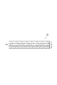
- FIG. 1 is a schematic sectional view of the transfer type photosensitive film according to the present embodiment.
- the transfer type photosensitive film 10 of the present embodiment has a structure in which a support film 1, an intermediate layer 2, a photosensitive resin layer 3, and a protective film 4 are laminated in this order.
- the transfer type photosensitive film of the present embodiment may be wound without the protective film 4.
- the photosensitive resin layer of the inner transfer type photosensitive film is adjacent to the photosensitive resin layer of the outer transfer type photosensitive film, so that the photosensitive resin layer is protected.
- a polymer film As the support film 1, a polymer film can be used.
- the material of the polymer film include polyethylene terephthalate, polycarbonate, polyethylene, polypropylene, polyethersulfone, and cycloolefin polymer.
- the thickness of the support film 1 is preferably 5 to 100 ⁇ m, and more preferably 10 to 70 ⁇ m, from the viewpoint of ensuring coverage and suppressing a decrease in resolution when light (active light) is irradiated through the support film 1. Is more preferably, and more preferably 15 to 40 ⁇ m, and particularly preferably 15 to 35 ⁇ m.
- the mid layer 2 can include a water-soluble polymer.
- the water-soluble polymer include polyvinyl alcohol, water-soluble salts of polyvinyl ether-maleic anhydride, water-soluble salts of carboxyalkyl starch, polyacrylamide, polyamide, water-soluble salts of polyacrylic acid, gelatin, polypropylene glycol, and polyvinylpyrrolidone.
- the intermediate layer preferably contains 50% by mass or more of polyvinyl alcohol, more preferably 60% by mass or more, and even more preferably 65% by mass or more.
- the content of polyvinyl alcohol in the intermediate layer is preferably equal to or less than 70% by mass, and more preferably equal to or less than 68% by mass.
- the saponification degree of polyvinyl alcohol is preferably 80 mol% or more, more preferably 83 mol% or more, and further preferably 85 mol% or more.
- the degree of saponification of polyvinyl alcohol is preferably equal to or less than 95 mol%, more preferably equal to or less than 93 mol%, and still more preferably equal to or less than 90 mol%.
- the intermediate layer preferably contains polyvinylpyrrolidone from the viewpoint of ensuring adhesion to the photosensitive resin layer.
- the content of polyvinylpyrrolidone in the intermediate layer is preferably from 41 to 49 parts by mass, more preferably from 43 to 47 parts by mass, based on 100 parts by mass of polyvinyl alcohol, from the viewpoint of ensuring adhesion to the photosensitive resin layer.
- the intermediate layer may contain additives such as a leveling agent, a release agent, and an adhesion promoter.
- the thickness of the intermediate layer is preferably from 3 to 30 ⁇ m, more preferably from 5 to 20 ⁇ m, and further preferably from 8 to 15 ⁇ m, from the viewpoint of achieving a high level of both the developability and the effect of suppressing voids. preferable.
- the photosensitive resin layer 3 includes a binder polymer (hereinafter, also referred to as a component (A)), a photopolymerizable compound (hereinafter, also referred to as a component (B)), and a photopolymerization initiator (hereinafter, also referred to as a component (C)). ) And a photosensitive resin composition containing:
- the component (A) is preferably a copolymer containing (a1) a structural unit derived from (meth) acrylic acid and (a2) a structural unit derived from an alkyl (meth) acrylate.
- the alkyl of the alkyl ester includes an alkyl group having a substituent and a cycloalkyl group.
- the content ratio of the constituent unit derived from (a1) (meth) acrylic acid in the component (A) is based on the total mass of the monomer constituting the component (A), because of excellent rust prevention. Is preferably 30% by mass or less, more preferably 25% by mass or less, and even more preferably 20% by mass or less.
- alkyl (meth) acrylate examples include methyl (meth) acrylate, ethyl (meth) acrylate, butyl (meth) acrylate, 2-ethylhexyl (meth) acrylate, Examples include cyclohexyl (meth) acrylate, cyclopentanyl (meth) acrylate, dicyclopentanyl (meth) acrylate and hydroxylethyl (meth) acrylate.
- the content of the (a2) alkyl (meth) acrylate-derived structural unit is determined based on the total amount of the monomers constituting the component (A). , 90% by mass or less, more preferably 89% by mass or less, even more preferably 88% by mass or less.
- the amount of the alkyl (meth) acrylate based on the total mass of the monomers constituting the component (A) is preferably 20% by mass or more.
- the component (A) preferably has a group containing an alicyclic structure in a side chain.
- a group can be introduced by a monomer containing a group having an alicyclic structure in a side chain.
- a monomer for example, cyclohexyl (meth) acrylate, cyclopentanyl (meth) acrylate, and dicyclopentanyl (meth) acrylate exemplified as the component (a2) can be used.
- the amount of the monomer containing a group having an alicyclic structure in the side chain is preferably from 5 to 70% by mass, and preferably from 20 to 60% by mass, based on the total mass of the monomers constituting the component (A). More preferably, it is more preferably 30 to 50% by mass.
- the above-mentioned copolymer may further contain a constituent unit derived from another monomer which can be copolymerized with the above-mentioned component (a1) and / or component (a2).
- Examples of other monomers copolymerizable with the component (a1) and / or the component (a2) include tetrahydrofurfuryl (meth) acrylate, dimethylaminoethyl (meth) acrylate, and (meth) acrylic acid.
- Acid diethylaminoethyl ester (meth) acrylic acid glycidyl ester, (meth) acrylic acid benzyl ester, 2,2,2-trifluoroethyl (meth) acrylate, 2,2,3,3-tetrafluoropropyl (meth) acrylate , (Meth) acrylamide, (meth) acrylonitrile, diacetone (meth) acrylamide, styrene, and vinyltoluene.
- one of the above monomers may be used alone, or two or more thereof may be used in combination.
- the weight average molecular weight of the binder polymer is preferably from 10,000 to 200,000, more preferably from 15,000 to 150,000, more preferably from 30,000 to 150,000, from the viewpoint of resolution. Is more preferably, and it is particularly preferably from 30,000 to 100,000, and most preferably from 40,000 to 100,000.
- the measurement conditions for the weight average molecular weight are the same as those in the examples of the present specification.
- the acid value of the binder polymer as the component (A) is preferably from 75 to 200 mgKOH / g, more preferably from 75 to 150 mgKOH / g, and more preferably from 75 to 120 mgKOH / g, from the viewpoint of excellent patterning properties. Is more preferred.
- the acid value of the binder polymer as the component (A) can be measured in the same manner as in the examples of the present specification.
- the glass transition temperature (Tg) of the binder polymer as the component (A) is preferably from 60 to 200 ° C, more preferably from 80 to 200 ° C, and from 100 to 200 ° C, from the viewpoint of securing reliability. Is more preferable.
- the glass transition temperature of the binder polymer as the component (A) can be measured in the same manner as in the examples of the present specification.
- a photopolymerizable compound having an ethylenically unsaturated group can be used as the photopolymerizable compound as the component (B).
- Examples of the photopolymerizable compound having an ethylenically unsaturated group include a monofunctional vinyl monomer, a bifunctional vinyl monomer, and a polyfunctional vinyl monomer having at least three polymerizable ethylenically unsaturated groups.
- Examples of the monofunctional vinyl monomer include, for example, (meth) acrylic acid, alkyl (meth) acrylate, and monomers copolymerizable therewith, as exemplified in the description of the component (A).
- bifunctional vinyl monomer examples include polyethylene glycol di (meth) acrylate, trimethylolpropane di (meth) acrylate, polypropylene glycol di (meth) acrylate, and bisphenol A polyoxyethylene polyoxypropylene di (meth) acrylate (2).
- the photosensitive resin composition of the present embodiment preferably contains a compound having a tricyclodecane skeleton or a tricyclodecene skeleton from the viewpoint of improving reliability.
- a compound includes a di (meth) acrylate compound represented by the following general formula (B-1).
- R 6 and R 7 each independently represent a hydrogen atom or a methyl group
- X represents a tricyclodecane skeleton or a divalent group having a tricyclodecene skeleton
- 8 and R 9 each independently represent an alkylene group having 1 to 4 carbon atoms
- n and m each independently represent an integer of 0 to 2
- p and q each independently represent an integer of 0 or more
- P + q 0 to 10.
- R 8 and R 9 are preferably an ethylene group or a propylene group, and more preferably an ethylene group.
- the propylene group may be any of an n-isopropylene group and an isopropylene group.
- the divalent group having a tricyclodecane skeleton or a tricyclodecene skeleton contained in X has a bulky structure, so that a low cured film is obtained. Moisture permeability can be improved.
- tricyclodecane skeleton and “tricyclodecene skeleton” in the present specification refer to the following structures, respectively (the bond is an arbitrary position).
- Examples of the compound having a tricyclodecane skeleton or a tricyclodecene skeleton include tricyclodecane dimethanol di (meth) acrylate and the like from the viewpoint of low moisture permeability of the obtained cured film pattern and improvement in adhesion to a conductor containing ITO.
- Compounds having a tricyclodecane skeleton are preferred. These are available as DCP and A-DCP (both manufactured by Shin-Nakamura Chemical Co., Ltd.).
- the proportion of the compound having a tricyclodecane skeleton or tricyclodecene skeleton is preferably from 100 parts by mass of the total amount of the photopolymerizable compound contained in the photosensitive resin composition from the viewpoint of improving reliability. It is preferably at least 25 parts by mass, more preferably at least 50 parts by mass, even more preferably at least 70 parts by mass, even more preferably at least 80 parts by mass. From the viewpoint of improving the reliability, the component (B) preferably contains a compound having a tricyclodecane skeleton or a tricyclodecene skeleton in an amount of 25 to 100% by mass based on the total amount of the component (B).
- Examples of the polyfunctional vinyl monomer having at least three polymerizable ethylenically unsaturated groups include, for example, trimethylolpropane tri (meth) acrylate, tetramethylol methane tri (meth) acrylate, tetramethylol methane tetra (meth) acrylate, Polyhydric alcohols such as pentaerythritol tri (meth) acrylate, dipentaerythritol penta (meth) acrylate, dipentaerythritol hexa (meth) acrylate, ditrimethylolpropanetetraacrylate and ⁇ , ⁇ -unsaturated carboxylic acids (for example, acrylic acid , Methacrylic acid, etc.) and a glycidyl group-containing compound such as trimethylolpropane triglycidyl ether tri (meth) acrylate and an ⁇ , ⁇ -unsaturated carboxylic acid
- the photosensitive resin composition of the present embodiment preferably contains a polyfunctional vinyl monomer having at least three polymerizable ethylenically unsaturated groups from the viewpoint of securing reliability by improving the crosslink density.
- a (meth) acrylate compound having a skeleton derived from pentaerythritol a (meth) acrylate compound having a skeleton derived from dipentaerythritol, and a skeleton derived from trimethylolpropane
- It preferably contains at least one selected from meth) acrylate compounds, and at least one selected from (meth) acrylate compounds having a skeleton derived from dipentaerythritol and (meth) acrylate compounds having a skeleton derived from trimethylolpropane More preferably, it comprises a species.
- the (meth) acrylate having a skeleton derived from dipentaerythritol means an esterified product of dipentaerythritol and (meth) acrylic acid, and the esterified product is a compound modified with an alkyleneoxy group.
- the above esterified product preferably has 6 ester bonds in one molecule, but may contain a compound having 1 to 5 ester bonds.
- the (meth) acrylate compound having a skeleton derived from trimethylolpropane means an esterified product of trimethylolpropane and (meth) acrylic acid, and the esterified product is a compound modified with an alkyleneoxy group.
- the above-mentioned esterified product preferably has three ester bonds in one molecule, but may contain a compound having one or two ester bonds.
- a compound obtained by dimerizing a trimethylolpropane di (meth) acrylate compound may be used as the (meth) acrylate compound having a skeleton derived from trimethylolpropane.
- the proportion of the monomer having at least three polymerizable ethylenically unsaturated groups is determined by the total amount of the photopolymerizable compounds contained in the photosensitive resin composition from the viewpoint of securing reliability by improving the crosslinking density.
- the amount is preferably at least 10 parts by mass, more preferably at least 30 parts by mass, even more preferably at least 50 parts by mass of the amount of 100 parts by mass.
- the content of the component (A) and the component (B) in the photosensitive resin composition of the present embodiment is such that the component (A) is 35 to 50 parts by mass, based on 100 parts by mass of the total of the components (A) and (B). 85 parts by weight, preferably 15 to 65 parts by weight of component (B), more preferably 40 to 80 parts by weight of component (A), and more preferably 20 to 60 parts by weight of component (B). More preferably, 50 to 70 parts by weight of component (B) and 30 to 50 parts by weight of component (B), 55 to 65 parts by weight of component (A) and 35 to 45 parts by weight of component (B). Is particularly preferred.
- the content of the component (A) and the component (B) is determined based on 100 parts by mass of the total of the components (A) and (B).
- the component is preferably at least 35 parts by mass, more preferably at least 40 parts by mass, even more preferably at least 50 parts by mass, particularly preferably at least 55 parts by mass, and component (B). Is preferably at least 15 parts by mass, more preferably at least 20 parts by mass, even more preferably at least 30 parts by mass, particularly preferably at least 35 parts by mass.
- the component (C) is not particularly limited as long as the photosensitive resin layer can be cured by irradiation with light (active light). From the viewpoint of transparency, an acylphosphine oxide-based photopolymerization initiator and an oxime ester-based photopolymerization initiator are preferable.
- acylphosphine oxide-based photopolymerization initiators 2,4,6-trimethylbenzoyl-diphenyl-phosphine oxide, bis (2,4,6-trimethylbenzoyl) -phenylphosphine oxide, 2,4,6- Trimethylbenzoyl-phosphinate.
- Acylphosphine oxide-based photopolymerization initiators are available as IRGACURE @ TPO, IRGACURE @ 819, and IRGACURE @ TPO-L (product names, manufactured by BASF Japan Ltd.).
- oxime ester-based photopolymerization initiator examples include a compound represented by the following general formula (1), a compound represented by the following general formula (2), and a compound represented by the following general formula (3).
- R 11 and R 12 each independently represent an alkyl group having 1 to 12 carbon atoms, a cycloalkyl group having 4 to 10 carbon atoms, a phenyl group or a tolyl group;
- An alkyl group, a cycloalkyl group having 4 to 6 carbon atoms, a phenyl group or a tolyl group is preferable, and an alkyl group having 1 to 4 carbon atoms, a cycloalkyl group having 4 to 6 carbon atoms, a phenyl group or a tolyl group is preferable.
- R 13 represents —H, —OH, —COOH, —O (CH 2 ) OH, —O (CH 2 ) 2 OH, —COO (CH 2 ) OH or —COO (CH 2 ) 2 OH; H, —O (CH 2 ) OH, —O (CH 2 ) 2 OH, —COO (CH 2 ) OH, or —COO (CH 2 ) 2 OH, preferably —H, —O (CH 2) ) 2 OH or -COO (CH 2 ) 2 OH is more preferred.
- R 14 each independently represent an alkyl group having 1 to 6 carbon atoms, and is preferably a propyl group.
- R 15 represents NO 2 or ArCO (where Ar represents an aryl group), and Ar is preferably a tolyl group.
- R 16 and R 17 each independently represent an alkyl group having 1 to 12 carbon atoms, a phenyl group or a tolyl group, preferably a methyl group, a phenyl group or a tolyl group.
- R 18 represents an alkyl group having 1 to 6 carbon atoms, and is preferably an ethyl group.
- R 19 is an organic group having an acetal bond, and is preferably a substituent corresponding to R 19 of a commercially available compound described below.
- R 20 and R 21 each independently represent an alkyl group having 1 to 12 carbon atoms, a phenyl group or a tolyl group, preferably a methyl group, a phenyl group or a tolyl group, and more preferably a methyl group.
- R 22 represents a hydrogen atom or an alkyl group.
- the compound represented by the general formula (1) is available as IRGACURE OXE 01 (product name, manufactured by BASF Japan Ltd.) or Adeka Cruz NCI-930 (product name, manufactured by ADEKA Corporation).
- the compound represented by the general formula (2) is available as DFI-091 or DFI-020 (product name, manufactured by Daito Chemmix Co., Ltd.).
- the compound represented by the general formula (3) is available as ADEKA OPTOMER N-1919 (product name, manufactured by ADEKA Corporation) or IRGACURE OXE 02 (product name, manufactured by BASF Japan Ltd.).
- the content of the component (C) is preferably 0.1 to 10 parts by mass with respect to 100 parts by mass of the total of the components (A) and (B) from the viewpoint of excellent photosensitivity and resolution.
- the amount is more preferably from 8 parts by mass, further preferably from 1 to 6 parts by mass, particularly preferably from 1 to 4 parts by mass.
- (D) a polymerization inhibitor hereinafter, also referred to as a (D) component
- (E) ) Leveling agent hereinafter sometimes referred to as component (E)
- (F) Rust inhibitor hereinafter sometimes referred to as component (F)
- (G) Adhesion aid hereinafter referred to as component (G))
- the photosensitive resin layer has a total light transmittance of preferably 85% or more, more preferably 90% or more, even more preferably 95% or more in a visible light region of a wavelength of 400 to 700 nm.
- the total light transmittance in the visible light region can be measured by the method described in Examples in this specification.
- the cured resin film after curing has the above total light transmittance.
- b * in the CIELAB color system is preferably -0.2 to 1.0, more preferably 0.0 to 0.7, and 0.1 to 0. .4 is more preferable. Note that b * in the CIELAB color system can be measured by the method described in the examples of the present specification.
- the cured resin film after curing has the above b * .
- the thickness of the photosensitive resin layer can be 2.5 ⁇ m or less in thickness after drying, and from the viewpoint of securing reliability and improving sensing sensitivity, is more preferably 0.5 ⁇ m or more and 2.0 ⁇ m or less. , 0.6 ⁇ m or more and 1.4 ⁇ m or less, particularly preferably 0.8 ⁇ m or more and 1.2 ⁇ m or less.
- the photosensitive resin layer 3 preferably has a contact angle of 60 to 90 ° with water on the surface S1 on the side of the cured photosensitive resin layer which is in contact with the intermediate layer.
- the photosensitive resin layer has such properties, it is possible to prevent the photosensitive resin layer from peeling off together with the protective film when peeling off the protective film while sufficiently securing the developability of the intermediate layer. It will be easier.
- the photosensitive film of the present embodiment is wound without a protective film, it is possible to prevent the photosensitive resin layer from peeling off to the adjacent support film side when the photosensitive film is pulled out.
- the contact angle is more preferably from 62 to 88 °, and still more preferably from 64 to 86 °.
- the above-mentioned contact angle can be measured by the method for measuring the contact angle 2 described in the examples of the present specification.
- the photosensitive resin layer preferably has a contact angle with water of 60 to 90 ° on the surface on the side opposite to the side in contact with the intermediate layer of the cured photosensitive resin layer,
- the angle is more preferably from 62 to 88 °, even more preferably from 64 to 86 °.
- This contact angle can be measured by the method for measuring the contact angle 1 described in the examples of the present specification.
- the photosensitive resin composition constituting the photosensitive resin layer preferably has a contact angle of 60 to 90 ° with water on the film surface when formed into a film.
- the angle is more preferably ⁇ 88 °, even more preferably 64 ⁇ ⁇ 86 °.
- the contact angle is obtained by dropping 1 mL of water on the surface of the film at a temperature of 25 ° C. and measuring the contact angle at this time with a contact angle meter.
- a hydrophilic component for example, a hydrophilic group
- a hydrophobic component for example, a hydrophobic group
- a method of adjusting the ratio between a hydrophilic component (for example, a hydrophilic group) and a hydrophobic component (for example, a hydrophobic group) in the photopolymerizable compound for example, (i) a hydrophilic component (for example, a hydrophilic group) and a hydrophobic component (for example, a hydrophobic group) in the photopolymerizable compound.
- the haze value of the cured photosensitive resin layer is preferably 0.01 to 1.0% from the viewpoint of improving the sensing sensitivity in a substrate or the like provided with a dielectrophoretic electrode used for a biosensor or the like, It is more preferably from 0.01 to 0.50%, further preferably from 0.01 to 0.30%, and particularly preferably from 0.01 to 0.25%.
- the haze value of the cured photosensitive resin layer is determined, for example, by transferring the photosensitive resin layer and the intermediate layer to a 1.0 mm-thick polycarbonate (PC) substrate, exposing the resin under a predetermined condition, and then removing the intermediate layer. It is determined from the value obtained by measuring the PC substrate / cured film laminate obtained from the cured film side.
- PC polycarbonate
- a polymer film can be used as the protective film 4 (cover film).
- the polymer film include a film made of polyethylene, polypropylene, polyethylene terephthalate, polycarbonate, a polyethylene-vinyl acetate copolymer, and a laminated film of a polyethylene-vinyl acetate copolymer and polyethylene.
- the thickness of the protective film 4 is preferably about 5 to 100 ⁇ m, but is preferably 70 ⁇ m or less, more preferably 60 ⁇ m or less, and further preferably 50 ⁇ m or less, from the viewpoint of being wound into a roll and stored. It is particularly preferable that the thickness be 40 ⁇ m or less.
- the photosensitive film 10 can be stored in a roll form or used.
- the photosensitive film of the present embodiment is formed by applying a coating solution for forming an intermediate layer on the support film 1 and drying, and then coating and drying the coating solution for forming a photosensitive resin layer on the intermediate layer 2 and forming the coating. It can be formed by sticking a protective film 40 on the photosensitive resin layer 3 thus formed.
- an intermediate layer is formed by preparing a coating liquid for forming an intermediate layer and a coating liquid for forming a photosensitive resin layer, and coating and drying the coating liquid on the support film 1 and the protective film 4, respectively.
- the photosensitive film can also be formed by laminating the support film thus formed and the protective film on which the photosensitive resin layer is formed in a state where the intermediate layer and the photosensitive resin layer face each other.
- the coating solution for forming the intermediate layer and the coating solution for forming the photosensitive resin layer can be prepared by uniformly dissolving or dispersing the components contained in the above-described intermediate layer and the components contained in the photosensitive resin layer in a solvent.
- the solvent is not particularly limited and known ones can be used.
- Examples include ethylene glycol monoethyl ether, diethylene glycol dimethyl ether, diethylene glycol ethyl methyl ether, diethylene glycol diethyl ether, propylene glycol monomethyl ether, ethylene glycol monobutyl ether acetate, diethylene glycol monoethyl ether acetate, propylene glycol monomethyl ether acetate, chloroform, and methylene chloride.
- One of these solvents may be used alone, or a mixed solvent of two or more solvents may be used.
- Examples of the coating method include a doctor blade coating method, a Meyer bar coating method, a roll coating method, a screen coating method, a spinner coating method, an inkjet coating method, a spray coating method, a dip coating method, a gravure coating method, a curtain coating method, and Die coating method may be mentioned.
- the drying conditions are not particularly limited, but the drying temperature is preferably from 60 to 130 ° C, and the drying time is preferably from 0.5 to 30 minutes.
- the bonding of the support film on which the intermediate layer is formed and the protective film on which the photosensitive resin layer is formed is performed by, for example, using a laminator at a heat roll temperature of 20 to 80 ° C., a pressure of 0.2 to 0.8 MPa, It can be carried out under the condition of a roll speed of 0.2 to 4.0 m / min.
- ⁇ Method of forming cured resin film> 2 and 3 are schematic cross-sectional views for explaining a method for forming a resin cured film according to the present embodiment.
- the method for forming a cured resin film according to the present embodiment includes a method of forming the above-described transfer photosensitive film 10 of the present embodiment on a base material 20 having a step 22 on one main surface (a stepped base material 24).
- Step S1 (see FIGS. 2A and 2B) of laminating the photosensitive resin layer 3 so that the photosensitive resin layer 3 covers the step 22 while peeling or peeling the photosensitive resin 4 from the photosensitive resin layer 3.
- Step S2 of irradiating a predetermined portion of the layer 3 with light L see FIG.
- Step S3 (see FIG. 3B) of forming the resin cured film 5 covering the step 22 by removing the intermediate layer 2 other than the predetermined portion of the photosensitive resin layer 3 by contacting the liquid.
- Step S3 (see FIG. 3B) of forming the resin cured film 5 covering the step 22 by removing the intermediate layer 2 other than the predetermined portion of the photosensitive resin layer 3 by contacting the liquid.
- Examples of the substrate 20 include polyethylene terephthalate and polycarbonate.
- a transparent electrode such as ITO, copper, copper / nickel alloy, gold, platinum, ruthenium, palladium, rhodium, silver, aluminum, nickel, chromium, zinc, tin, etc., or a dielectrophoresis including the metal material Examples include those caused by electrodes, optical sensors, and the like. Two or more of these may be provided, or two or more thereof may be provided.
- Examples of the stepped substrate 24 include a substrate provided with a dielectrophoretic electrode used for a biosensor or the like, an optical sensor substrate, a touch sensor substrate for a touch panel, and the like.
- a pressure roll may be used.
- the pressure roll may be provided with a heating means so as to be able to heat and pressure.
- the heating temperature in the case of thermocompression bonding, the adhesiveness between the photosensitive resin layer and the substrate, and, from the viewpoint of obtaining the ability to follow steps, so that the components of the photosensitive resin layer are not easily thermoset or thermally decomposed.
- the temperature is preferably from 10 to 180 ° C, more preferably from 20 to 160 ° C, even more preferably from 30 to 150 ° C.
- the pressure at the time of heating and pressing is preferably 50 to 1 ⁇ 10 5 N / m as a linear pressure, and 2.5 ⁇ 10 2 to 5 ⁇ 10 4 N / m. More preferably, it is more preferably 5 ⁇ 10 2 to 4 ⁇ 10 4 N / m.
- the substrate is preheated.
- the preheating temperature at this time is preferably 30 to 180 ° C.
- step S2 of the present embodiment a predetermined portion of the photosensitive resin layer is irradiated with light (active rays) L in a pattern via the photomask 30 (see FIG. 3A).
- the actinic ray When irradiating with an actinic ray, the actinic ray is irradiated as it is when the support film on the intermediate layer is transparent (for example, when a transparent polymer film is used as the support film, the polymer film remains). If it is opaque, it can be removed before irradiation with actinic light.
- a known actinic light source can be used, and examples thereof include a carbon arc lamp, an ultra-high pressure mercury lamp, a high pressure mercury lamp, and a xenon lamp. Can be used.
- the dose of the actinic ray L is usually 1 ⁇ 10 2 to 1 ⁇ 10 4 J / m 2 , and the irradiation may be accompanied by heating.
- the actinic ray irradiation amount is within the above range, it becomes easy to achieve both sufficient photocuring and suppression of discoloration of the photosensitive resin layer.
- step S3 of the present embodiment the photosensitive resin layer and the intermediate layer after the irradiation with the actinic ray are developed with a developer, and the portion of the photosensitive resin layer to which the actinic ray has not been irradiated (that is, the photosensitive resin layer) Are removed) and the intermediate layer is removed to form a cured resin film 5 covering the step (see FIG. 3B).
- the formed resin cured film 5 can have a predetermined pattern.
- the support film After the irradiation with the actinic ray, if the support film is laminated on the intermediate layer, the support film is removed, and then development is performed in which the portion not irradiated with the actinic ray is removed with a developer.
- development is performed by a known method such as spraying, showering, rocking immersion, brushing, and scrubbing using a known developing solution such as an alkaline aqueous solution, an aqueous developing solution, and an organic solvent to remove unnecessary portions.
- a known developing solution such as an alkaline aqueous solution, an aqueous developing solution, and an organic solvent to remove unnecessary portions.
- Examples of the base of the aqueous alkali solution include alkali hydroxides (such as lithium, sodium or potassium hydroxide), alkali carbonates (such as lithium, sodium or potassium carbonate or bicarbonate), and alkali metal phosphates (such as potassium phosphate). , Sodium phosphate, etc.), alkali metal pyrophosphates (sodium pyrophosphate, potassium pyrophosphate, etc.), tetramethylammonium hydroxide, triethanolamine, etc., among which tetramethylammonium hydroxide, etc. are preferred.
- alkali hydroxides such as lithium, sodium or potassium hydroxide
- alkali carbonates such as lithium, sodium or potassium carbonate or bicarbonate
- alkali metal phosphates such as potassium phosphate
- Sodium phosphate, etc. alkali metal pyrophosphates
- alkali metal pyrophosphates sodium pyrophosphate, potassium pyrophosphate, etc.
- an aqueous solution of sodium carbonate is preferably used.
- a dilute solution of sodium carbonate at 20 to 50 ° C. (0.5 to 5% by mass aqueous solution) is preferably used.
- the development temperature and time can be adjusted according to the developability of the photosensitive resin layer and the intermediate layer of the present embodiment.
- a surfactant an antifoaming agent, a small amount of an organic solvent for accelerating the development, and the like can be mixed in the aqueous alkali solution.
- the base of the aqueous alkali solution remaining in the photosensitive resin layer after photo-curing using an organic acid, an inorganic acid or an aqueous solution of these acids, spraying, rocking immersion, brushing, scrubbing and the like by known methods.
- Acid treatment neutralization treatment
- the resin cured film pattern may be further cured by irradiation with actinic rays (for example, 5 ⁇ 10 3 to 2 ⁇ 10 4 J / m 2 ). Further, if necessary, a heat treatment (80 to 250 ° C.) may be performed instead of or in combination with the irradiation of active light after development.
- actinic rays for example, 5 ⁇ 10 3 to 2 ⁇ 10 4 J / m 2 .
- a heat treatment 80 to 250 ° C.
- the method for forming a resin cured film of the present embodiment described above can be used as a method for manufacturing a sensor substrate with a resin cured film. That is, a substrate having a transparent electrode and / or wiring on one main surface (for example, a touch sensor substrate) or a substrate having a dielectrophoretic electrode (for example, a biosensor substrate) is prepared as the stepped base material 24, Through the same steps as described above, a sensor substrate with a cured resin film provided with a cured resin film covering the transparent electrode and / or the wiring or the dielectrophoretic electrode can be obtained.
- a sensor substrate with a resin cured film provided with a dielectrophoretic electrode can also function as a resin cured film as a dielectric film, and can be applied to a device that may come into contact with a liquid sample (eg, a microorganism measuring device). .
- the stepped substrate is an optical sensor substrate having an optical sensor on one principal surface
- Such a sensor substrate with a cured resin film can be applied to an apparatus (for example, a food inspection apparatus) that may be contaminated by moisture or the like.
- Binder polymer solution A1 Binder polymer solution A1 (1) shown in Table 1 was charged into a flask equipped with a stirrer, a reflux condenser, an inert gas inlet, and a thermometer, and the temperature was raised to 80 ° C. in a nitrogen gas atmosphere. While maintaining the reaction temperature at 80 ° C. ⁇ 2 ° C., (2) shown in Table 1 was dropped uniformly over 4 hours. After the dropwise addition of (2), stirring was continued at 80 ° C. ⁇ 2 ° C. for 6 hours to obtain a solution (A1) of a binder polymer having a weight average molecular weight of 45000 (solid content: 50% by mass) (A1). The acid value of the binder polymer was 114.2 mgKOH / g. The glass transition temperature (Tg) was 60 ° C.
- Binder polymer solutions A2 to A6 were obtained in the same manner as for binder polymer solution A1, except that the amounts were changed as shown in Table 1.
- Table 1 shows the weight average molecular weight, acid value and Tg of the binder polymer.
- the weight average molecular weight, acid value and glass transition temperature of the binder polymer were determined by the following measurement methods.
- the weight average molecular weight (Mw) was measured by gel permeation chromatography (GPC) and derived by conversion using a calibration curve of standard polystyrene. GPC measurement conditions are shown below. ⁇ GPC measurement conditions> Pump: Hitachi L-6000 type (product name, manufactured by Hitachi, Ltd.) Columns: Gelpack GL-R420, Gelpack GL-R430, Gelpack GL-R440 (product names, manufactured by Hitachi Chemical Co., Ltd.) Eluent: tetrahydrofuran Measurement temperature: 40 ° C Sample concentration: Collected 120 mg of a resin solution of 50% by mass NV (nonvolatile content) and dissolved in 5 mL of THF. Injection volume: 200 ⁇ L Flow rate: 2.05 mL / min Detector: Hitachi L-3300 RI (product name, manufactured by Hitachi, Ltd.)
- the acid value was measured by a neutralization titration method based on JIS K0070 as shown below. First, the binder polymer solution was heated at 130 ° C. for 1 hour to remove volatile components to obtain a solid component. Then, after precisely weighing 1.0 g of the solid polymer, 30 g of acetone was added to the polymer, and this was uniformly dissolved to obtain a resin solution. Then, an appropriate amount of phenolphthalein as an indicator was added to the resin solution, and titration was performed using a 0.1 mol / L aqueous potassium hydroxide solution. Then, the acid value was calculated by the following equation.
- Acid value 0.1 ⁇ V ⁇ f 1 ⁇ 56.1 / (Wp ⁇ I / 100)
- V is indicated the titer of the aqueous potassium hydroxide solution of 0.1 mol / L was used for titration (mL)
- f 1 represents a factor of the aqueous potassium hydroxide 0.1 mol / L (concentration conversion factor)
- Wp represent the measured mass (g) of the resin solution
- I represents the measured proportion (mass%) of the nonvolatile components in the resin solution.
- Tg glass transition temperature
- the exposed film was heated on a hot plate at 65 ° C. for 2 minutes, then at 95 ° C. for 8 minutes, and heat-treated at 180 ° C. for 60 minutes by a hot air convection dryer.
- the formed cured film was peeled off from the polyethylene terephthalate film, and the coefficient of thermal expansion of the cured film when the temperature was increased at a heating rate of 5 ° C./min was measured using TMA / SS6000 manufactured by Seiko Instruments Inc. The inflection point obtained from the curve was determined as the glass transition temperature Tg.
- a coating liquid R1 for forming a photosensitive resin layer containing a photosensitive resin composition for forming a photosensitive resin layer by mixing the components shown in Table 3 in the amounts (units: parts by mass) shown in the table. To R10 were each prepared. In addition, the compounding amount other than the solvent in Table 3 is a compounding amount in solid content.
- A-TMMT pentaerythritol tetraacrylate
- A-DCP Tricyclodecane dimethanol diacrylate (product name “A-DCP” manufactured by Shin-Nakamura Chemical Co., Ltd.)
- BPE-100 Ethoxylated bisphenol A dimethacrylate (Shin-Nakamura Chemical Co., Ltd. product name "BPE-100")
- Component Antage W-500 2,2′-methylene-bis (4-ethyl-6-tert-butylphenol) (product name “Antage W-500” manufactured by Kawaguchi Chemical Industry Co., Ltd.)
- Component Additive 8032 Organically modified silicone oil (manufactured by Toray Dow Corning Co., Ltd., product name “Additive 8032”)
- Solvent MEK methyl ethyl ketone (manufactured by Tonen Chemical GK)
- a polypropylene film is adhered as a protective film, and a support film, an intermediate layer, a photosensitive resin layer, and a protective film are laminated on the photosensitive film in this order. Obtained.
- Comparative Examples 3 and 4 In Comparative Examples 3 and 4, since the intermediate layer was not provided, the coating liquid for forming the photosensitive resin layer shown in Table 6 was uniformly coated on a 16 ⁇ m-thick polyethylene terephthalate film prepared as a support film using a bar coater. And dried on a hot plate at 80 ° C. for 20 minutes to form photosensitive resin layers having a thickness of 1 ⁇ m (Comparative Example 3) and 3 ⁇ m (Comparative Example 4) after drying.
- a polypropylene film was laminated as a protective film on the formed photosensitive resin layer to obtain a photosensitive film in which a support film, a photosensitive resin layer, and a protective film were laminated in this order.
- Example 13 A coating solution for forming a photosensitive resin layer shown in Table 5 was uniformly applied on a polypropylene film prepared as a protective film using a bar coater, dried on a hot plate at 80 ° C. for 5 minutes, and dried. Is 1 ⁇ m.
- the above-prepared intermediate layer having a thickness of 5 ⁇ m is laminated, and a support film, an intermediate layer, a photosensitive resin layer, and a protective film are laminated in this order.
- a photosensitive film was obtained.
- the lamination was performed using a laminator “MRK-650Y” (product name, manufactured by MCK Co., Ltd.) under the conditions of a heat roll temperature of 25 ° C., a pressure of 0.40 MPa, and a roll speed of 0.6 m / min.
- a photosensitive resin layer was laminated on a glass substrate (length 6 cm ⁇ width 6 cm, thickness 1 mm).
- Lamination was performed using a laminator “MRK-650Y” (product name, manufactured by MCK Co., Ltd.) under the conditions of a heat roll temperature of 110 ° C., a pressure of 0.40 MPa, and a roll speed of 0.6 m / min.
- MRK-650Y product name, manufactured by MCK Co., Ltd.
- the laminate 1 was measured at an exposure amount of 60 mJ / cm 2 (i-line (wavelength: 365 nm)) from the support film side. ) was irradiated with ultraviolet light. Thereafter, the support film was peeled off, and ultraviolet rays were irradiated from the intermediate layer side at an exposure amount of 1000 mJ / cm 2 (i-line (wavelength: 365 nm)) to obtain a laminate 2.
- the exposed laminate 2 was developed with a 1% by mass aqueous solution of sodium carbonate.
- the development was performed using a developing machine under the conditions of a spray pressure of 0.2 MPa, a temperature of 30 ° C., and a development time of 30 seconds, to obtain a laminate 3.
- the laminate 4 was measured at an exposure amount of 60 mJ / cm 2 (i-line (wavelength: 365 nm)) from the support film side. ) was irradiated with ultraviolet light. Thereafter, the support film was peeled off, and a laminate 5 was produced. At a temperature of 25 ° C., 1 mL of water was dropped on the surface of the cured resin film of the laminate 5, and the contact angle at this time was measured with a contact angle meter.
- EXM1201 product name, manufactured by Oak Manufacturing Co., Ltd.
- a photosensitive resin layer was laminated on the copper substrate while peeling off the protective film of each photosensitive film.
- Lamination was performed using a laminator “MRK-650Y” (product name, manufactured by MCK Co., Ltd.) under the conditions of a heat roll temperature of 110 ° C., a pressure of 0.40 MPa, and a roll speed of 0.6 m / min.
- MRK-650Y product name, manufactured by MCK Co., Ltd.
- the number of laminate voids (bubbles) in the groove was measured by observing the laminate 6 from the intermediate layer side with a microscope “BX-60” (manufactured by Olympus Corporation), and the followability was evaluated based on the following criteria.
- a photosensitive resin layer was laminated on a polycarbonate substrate (6 cm long ⁇ 6 cm wide, 1 mm thick, manufactured by Mitsubishi Gas Chemical Co., Ltd.). Lamination was performed using a laminator “MRK-650Y” (product name, manufactured by MCK Co., Ltd.) under the conditions of a heat roll temperature of 110 ° C., a pressure of 0.40 MPa, and a roll speed of 0.6 m / min. Thus, a laminate A in which the glass substrate, the photosensitive resin layer, the intermediate layer, and the support film were laminated in this order was obtained.
- MRK-650Y product name, manufactured by MCK Co., Ltd.
- the laminated body A was measured at an exposure amount of 60 mJ / cm 2 (i-line (wavelength: 365 nm)) from the support film side. ) was irradiated with ultraviolet light. Thereafter, the support film was peeled off, and ultraviolet rays were further irradiated from the intermediate layer side at an exposure amount of 1000 mJ / cm 2 (measured value at i-line (wavelength: 365 nm)).
- the exposed layered product A was developed with a 1% by mass aqueous solution of sodium carbonate.
- the development was performed using a developing machine under the conditions of a spray pressure of 0.2 MPa, a temperature of 30 ° C., and a development time of 30 seconds, to obtain a laminate B.
- the total light transmittance (including the substrate) of the laminate A and the laminate B was measured using a turbidimeter (NDH5000).
- NDH5000 turbidimeter
- b * in the CIELAB color system was measured using a spectrophotometer CM-5 (manufactured by Konica Minolta) at a light source setting of D65 and a viewing angle of 2 °.
Landscapes
- Physics & Mathematics (AREA)
- General Physics & Mathematics (AREA)
- Chemical & Material Sciences (AREA)
- Chemical Kinetics & Catalysis (AREA)
- Electrochemistry (AREA)
- Health & Medical Sciences (AREA)
- Life Sciences & Earth Sciences (AREA)
- Analytical Chemistry (AREA)
- Biochemistry (AREA)
- General Health & Medical Sciences (AREA)
- Immunology (AREA)
- Pathology (AREA)
- Materials For Photolithography (AREA)
Abstract
転写型感光性フィルムは、支持フィルムと、水溶性高分子を含む中間層と、感光性樹脂層とがこの順に積層された構造を有し、感光性樹脂層は、厚みが2.5μm以下であり、且つ、硬化後の感光性樹脂層の中間層と接する側の表面における水に対する接触角が60~90°である。
Description
本発明は、転写型感光性フィルム、樹脂硬化膜の形成方法及び樹脂硬化膜付センサ基板の製造方法に関する。
タッチパネル等の画像表示装置に利用されるセンサ基板として、静電容量方式のタッチセンサ基板が知られている。タッチセンサ基板上には、ITOなどの透明電極及び銅又は銅/ニッケル合金などの配線が設けられており、これらの電極及び配線を保護するために保護膜が設けられる場合がある。この場合、画像の品質に影響が出ないように、光透過性に優れた材料で保護膜を形成する必要がある。
また、微生物測定装置に利用されるセンサ基板として、誘電泳動電極が設けられたバイオセンサ基板が知られている。例えば、下記特許文献1には、微生物等の液体試料中の微粒子を誘電泳動法にて捕集するための櫛型電極パターンが開示されている。この電極パターン上には、液体試料から電気絶縁するための誘電膜を設ける場合がある。この場合、捕集した微粒子を光学的に観察或いは分析する際に悪影響が出にくいように、光透過性に優れた材料で誘電膜を形成することが望ましい。
透明な膜を設ける手段としては、例えば、バインダーポリマー、光重合性化合物及び光重合開始剤が含まれる感光性樹脂層を有する感光性フィルムが知られている。このような感光性フィルムによれば、基材上に感光性樹脂層をラミネートし、露光及び現像を行うことにより、所定のパターン形状を有する樹脂硬化膜を簡便に形成することができる。
上述したタッチセンサ基板又はバイオセンサ基板上に保護膜又は誘電膜を設ける場合、感度向上の点から、膜の厚みをより薄くすることが求められる。しかし、感光性樹脂層の厚みを薄くすると、ラミネート時にボイド(気泡)が発生しやすくなるという問題がある。特に、タッチパネル又は微生物測定装置などのセンサは、繊細なパターンが設けられており、その凹部にボイドが残りやすくなっている。
本発明は、段差を有する基材上であってもボイドの発生を充分抑制しつつ薄膜の樹脂硬化膜を良好に形成することができる転写型感光性フィルム、樹脂硬化膜の形成方法及び樹脂硬化膜付センサ基板の製造方法を提供することを目的とする。
上記課題を解決するために本発明者らは鋭意検討した結果、支持フィルムと感光性樹脂層との間に水溶性高分子を含む中間層を設け、感光性樹脂層が特定の親水性を示すように組成を調整することにより、薄膜化した感光性樹脂層を段差のある基材上にラミネートしてもボイド発生を充分抑制することでき、なおかつ中間層を設けたことに起因する問題も解消することができることを見出し、本発明を完成するに至った。
本発明は、支持フィルムと、水溶性高分子を含む中間層と、感光性樹脂層とがこの順に積層された構造を有し、感光性樹脂層は、厚みが2.5μm以下であり、且つ、硬化後の感光性樹脂層の中間層と接する側の表面における水に対する接触角が60~90°である転写型感光性フィルムを提供する。
本発明の転写型感光性フィルムによれば、段差を有する基材上であってもボイドの発生を充分抑制しつつ薄膜の樹脂硬化膜を良好に形成することができる。
すなわち、転写型感光性フィルムが、水溶性高分子を含む中間層と、特定の親水性を示す感光性樹脂層との組み合わせを有することにより、ラミネート時においては、感光性フィルムの厚みが充分確保されることで感光性樹脂層の段差への追従性が向上し、ラミネート後には現像によって中間層は除去されて薄膜の樹脂硬化膜のみを残すことができる。また、中間層と感光性樹脂層とが適度に親和していることで、例えば、感光性樹脂層の中間層とは反対側に保護フィルムが設けられている場合、保護フィルムを剥離するときに感光性樹脂層が保護フィルムとともに剥離することを抑制でき、保護フィルムなしに巻回されている場合、感光性フィルムを引き出すときに感光性樹脂層が隣接する支持フィルム側に剥離することを抑制できる。
本発明の転写型感光性フィルムは、ラミネート時の追従性を向上させる観点から、上記中間層がポリビニルアルコールを50質量%以上含んでいてもよい。
また、樹脂硬化膜の光学特性を更に良好にする観点から、上記感光性樹脂層は、波長400~700nmの可視光領域における全光線透過率が85%以上であることが好ましい。
更に、樹脂硬化膜の光学特性を更に良好にする観点から、上記感光性樹脂層は、CIELAB表色系でのb*が-0.2~1.0であることが好ましい。
また、現像性とボイドの抑制効果とを高水準で両立する観点から、上記中間層は、厚みが3~30μmであることが好ましい。
本発明の転写型感光性フィルムは、バイオセンサ基板上に保護膜を形成するために用いるものであってもよい。
本発明の転写型感光性フィルムは、誘電泳動電極を有するバイオセンサ基板の誘電泳動電極上に保護膜を形成するために用いるものであってもよい。
本発明はまた、一主面上に段差を有する基材上に、上記本発明に係る転写型感光性フィルムを、感光性樹脂層が段差を被覆するようにラミネートする工程と、基材上の感光性樹脂層の所定部分に光を照射する工程と、感光性樹脂層及び中間層に、支持フィルムが除去された状態の中間層側から現像液を接触させることにより、感光性樹脂層の所定部分以外及び中間層を除去し、段差を被覆する樹脂硬化膜を形成する工程とを備える樹脂硬化膜の形成方法を提供する。
本発明の樹脂硬化膜の形成方法によれば、段差を有する基材上にボイドの発生を充分抑制しつつ薄膜の樹脂硬化膜を形成することができる。また、転写型感光性フィルムが、感光性樹脂層の中間層とは反対側に保護フィルムを備える場合、保護フィルムを剥離するときに感光性樹脂層が保護フィルムとともに剥離することを抑制でき、保護フィルムなしに巻回されている場合、感光性フィルムを引き出すときに感光性樹脂層が隣接する支持フィルム側に剥離することを抑制できる。
上記段差が、基材の主面上に設けられた透明電極及び/又は配線に起因する段差であってもよい。
上記段差が、基材の主面上に設けられた誘電泳動電極に起因する段差であってもよい。
本発明はまた、一主面上に透明電極及び/又は配線を有する基板上に、上記本発明に係る転写型感光性フィルムを、感光性樹脂層が透明電極及び/又は配線を被覆するようにラミネートする工程と、基板上の感光性樹脂層の所定部分に光を照射する工程と、光照射された感光性樹脂層及び中間層に、支持フィルムが除去された状態の中間層側から現像液を接触させることにより、感光性樹脂層の所定部分以外及び中間層を除去し、透明電極及び/又は配線を被覆する樹脂硬化膜を形成する工程とを備える樹脂硬化膜付センサ基板の第1の製造方法を提供する。
本発明の第1の樹脂硬化膜付センサ基板の製造方法によれば、透明電極及び/又は配線の保護膜として、薄膜でありながらもボイドが充分に少ない樹脂硬化膜を備えるセンサ基板を得ることができる。
本発明はまた、一主面上に誘電泳動電極を有する基板上に、上記本発明に係る転写型感光性フィルムを、感光性樹脂層が誘電泳動電極を被覆するようにラミネートする工程と、基板上の感光性樹脂層の所定部分に光を照射する工程と、光照射された感光性樹脂層及び中間層に、支持フィルムが除去された状態の中間層側から現像液を接触させることにより、感光性樹脂層の所定部分以外及び中間層を除去し、誘電泳動電極を被覆する樹脂硬化膜を形成する工程とを備える樹脂硬化膜付センサ基板の第2の製造方法を提供する。
本発明の樹脂硬化膜付センサ基板の製造方法によれば、誘電泳動電極の誘電膜として、薄膜でありながらもボイドが充分に少ない樹脂硬化膜を備えるセンサ基板を得ることができる。このセンサ基板は、バイオセンサとして好適に用いることができる。
本発明によれば、段差を有する基材上であってもボイドの発生を充分抑制しつつ薄膜の樹脂硬化膜を形成することができる転写型感光性フィルム、樹脂硬化膜の形成方法及び樹脂硬化膜付センサ基板の製造方法を提供することができる。
以下、場合により図面を参照しつつ、本発明を実施するための形態について詳細に説明する。ただし、本発明は以下の実施形態に限定されるものではない。なお、本明細書において、「(メタ)アクリル酸」とは、アクリル酸又はメタクリル酸を意味し、「(メタ)アクリレート」とは、アクリレート又はそれに対応するメタクリレートを意味する。「A又はB」とは、AとBのどちらか一方を含んでいればよく、両方とも含んでいてもよい。
また、本明細書において「層」との語は、平面図として観察したときに、全面に形成されている形状の構造に加え、一部に形成されている形状の構造も包含される。また、本明細書において「工程」との語は、独立した工程だけではなく、他の工程と明確に区別できない場合であってもその工程の所期の作用が達成されれば、本用語に含まれる。また、「~」を用いて示された数値範囲は、「~」の前後に記載される数値をそれぞれ最小値及び最大値として含む範囲を示す。
さらに、本明細書において組成物中の各成分の含有量は、組成物中に各成分に該当する物質が複数存在する場合、特に断らない限り、組成物中に存在する当該複数の物質の合計量を意味する。また、例示材料は特に断らない限り単独で用いてもよいし、2種以上を組み合わせて用いてもよい。
また、本明細書中に段階的に記載されている数値範囲において、ある段階の数値範囲の上限値又は下限値は、他の段階の数値範囲の上限値又は下限値に置き換えてもよい。また、本明細書中に記載されている数値範囲において、その数値範囲の上限値又は下限値は、実施例に示されている値に置き換えてもよい。
<転写型感光性フィルム>
図1は、本実施形態に係る転写型感光性フィルムの模式断面図である。本実施形態の転写型感光性フィルム10は、支持フィルム1と、中間層2と、感光性樹脂層3と、保護フィルム4とがこの順に積層された構造を有する。本実施形態の転写型感光性フィルムは、保護フィルム4が省略されて巻回されているものであってもよい。この場合、外側の転写型感光性フィルムの感光性樹脂層に内側の転写型感光性フィルムの支持フィルムが隣接することで、感光性樹脂層が保護される。
図1は、本実施形態に係る転写型感光性フィルムの模式断面図である。本実施形態の転写型感光性フィルム10は、支持フィルム1と、中間層2と、感光性樹脂層3と、保護フィルム4とがこの順に積層された構造を有する。本実施形態の転写型感光性フィルムは、保護フィルム4が省略されて巻回されているものであってもよい。この場合、外側の転写型感光性フィルムの感光性樹脂層に内側の転写型感光性フィルムの支持フィルムが隣接することで、感光性樹脂層が保護される。
[支持フィルム]
支持フィルム1としては、重合体フィルムを用いることができる。重合体フィルムの材質としては、ポリエチレンテレフタレート、ポリカーボネート、ポリエチレン、ポリプロピレン、ポリエーテルサルフォン、シクロオレフィンポリマー等が挙げられる。
支持フィルム1としては、重合体フィルムを用いることができる。重合体フィルムの材質としては、ポリエチレンテレフタレート、ポリカーボネート、ポリエチレン、ポリプロピレン、ポリエーテルサルフォン、シクロオレフィンポリマー等が挙げられる。
支持フィルム1の厚みは、被覆性の確保と、支持フィルム1を介して光(活性光線)を照射する際の解像度の低下を抑制する観点から、5~100μmであることが好ましく、10~70μmであることがより好ましく、15~40μmであることが更に好ましく、15~35μmであることが特に好ましい。
[中間層]
中間層2は、水溶性高分子を含むことができる。水溶性高分子としては、ポリビニルアルコール、ポリビニルエーテル-無水マレイン酸水溶性塩類、カルボキシアルキル澱粉水溶性塩類、ポリアクリルアミド、ポリアミド、ポリアクリル酸水溶性塩類、ゼラチン、ポリプロピレングリコール、ポリビニルピロリドンが挙げられる。
中間層2は、水溶性高分子を含むことができる。水溶性高分子としては、ポリビニルアルコール、ポリビニルエーテル-無水マレイン酸水溶性塩類、カルボキシアルキル澱粉水溶性塩類、ポリアクリルアミド、ポリアミド、ポリアクリル酸水溶性塩類、ゼラチン、ポリプロピレングリコール、ポリビニルピロリドンが挙げられる。
ラミネート時の追従性を向上させる観点から、中間層がポリビニルアルコールを50質量%以上含有することが好ましく、60質量%以上含有することがより好ましく、65質量%以上含有することが更に好ましい。感光性樹脂層と中間層との密着性確保の観点から、中間層におけるポリビニルアルコールの含有量は、70質量%以下であることが好ましく、68質量%以下であることがより好ましい。
ポリビニルアルコールのけん化度は、耐水性の観点から、80モル%以上が好ましく、83モル%以上がより好ましく、85モル%以上が更に好ましい。現像性の観点から、ポリビニルアルコールのけん化度は、95モル%以下が好ましく、93モル%以下がより好ましく、90モル%以下が更に好ましい。
中間層は、感光性樹脂層との密着性確保の観点から、ポリビニルピロリドンを含有することが好ましい。中間層におけるポリビニルピロリドンの含有量は、感光性樹脂層との密着性確保の観点から、ポリビニルアルコール100質量部に対して、41~49質量部が好ましく、43~47質量部がより好ましい。
中間層は、レベリング剤、離型剤、密着付与剤などの添加剤が含まれていてもよい。
中間層は、現像性とボイドの抑制効果とを高水準で両立する観点から、厚みが3~30μmであることが好ましく、5~20μmであることがより好ましく、8~15μmであることが更に好ましい。
[感光性樹脂層]
感光性樹脂層3は、バインダーポリマー(以下、(A)成分ともいう)と、光重合性化合物(以下、(B)成分ともいう)と、光重合開始剤(以下、(C)成分ともいう)と、を含有する感光性樹脂組成物から形成することができる。
感光性樹脂層3は、バインダーポリマー(以下、(A)成分ともいう)と、光重合性化合物(以下、(B)成分ともいう)と、光重合開始剤(以下、(C)成分ともいう)と、を含有する感光性樹脂組成物から形成することができる。
(A)成分は、(a1)(メタ)アクリル酸に由来する構成単位、及び(a2)(メタ)アクリル酸アルキルエステルに由来する構成単位を含有する共重合体が好適である。なお、ここでいうアルキルエステルのアルキルには、置換基を有するアルキル基、及びシクロアルキル基も包含される。
(A)成分における(a1)(メタ)アクリル酸由来の構成単位の含有割合は、防錆性に優れる点から、(A)成分を構成するモノマーの全質量を基準とする(メタ)アクリル酸の配合量が、30質量%以下であることが好ましく、25質量%以下であることがより好ましく、20質量%以下であることが更に好ましい。
(a2)(メタ)アクリル酸アルキルエステルとしては、例えば、(メタ)アクリル酸メチルエステル、(メタ)アクリル酸エチルエステル、(メタ)アクリル酸ブチルエステル、(メタ)アクリル酸2-エチルヘキシルエステル、(メタ)アクリル酸シクロヘキシル、(メタ)アクリル酸シクロペンタニル、(メタ)アクリル酸ジシクロペンタニル及び(メタ)アクリル酸ヒドロキシルエチルエステルが挙げられる。
(A)成分における(a2)(メタ)アクリル酸アルキルエステル由来の構成単位の含有割合は、(A)成分を構成するモノマーの全質量を基準とする(メタ)アクリル酸アルキルエステルの配合量が、90質量%以下であることが好ましく、89質量%以下であることがより好ましく、88質量%以下であることが更に好ましい。また、(A)成分を構成するモノマーの全質量を基準とする(メタ)アクリル酸アルキルエステルの配合量は、20質量%以上であることが好ましい。
密着性向上の観点から、(A)成分は、脂環構造を含有する基を側鎖に有することが好ましい。このような基は、側鎖に脂環構造を有する基を含有するモノマーによって導入することができる。このようなモノマーとしては、例えば、(a2)成分として例示した(メタ)アクリル酸シクロヘキシル、(メタ)アクリル酸シクロペンタニル、及び(メタ)アクリル酸ジシクロペンタニルを用いることができる。
側鎖に脂環構造を有する基を含有するモノマーの配合量は、(A)成分を構成するモノマーの全質量を基準として、5~70質量%であることが好ましく、20~60質量%であることがより好ましく、30~50質量%であることが更に好ましい。
上記共重合体は、更に、上記の(a1)成分及び/又は(a2)成分と共重合し得るその他のモノマー由来の構成単位を含有していてもよい。
上記の(a1)成分及び/又は(a2)成分と共重合し得るその他のモノマーとしては、例えば、(メタ)アクリル酸テトラヒドロフルフリルエステル、(メタ)アクリル酸ジメチルアミノエチルエステル、(メタ)アクリル酸ジエチルアミノエチルエステル、(メタ)アクリル酸グリシジルエステル、(メタ)アクリル酸ベンジルエステル、2,2,2-トリフルオロエチル(メタ)アクリレート、2,2,3,3-テトラフルオロプロピル(メタ)アクリレート、(メタ)アクリルアミド、(メタ)アクリロニトリル、ジアセトン(メタ)アクリルアミド、スチレン、及びビニルトルエンが挙げられる。(A)バインダーポリマーを合成する際、上記のモノマーは、1種を単独で用いてもよいし、2種以上を組み合わせて用いてもよい。
(A)バインダーポリマーの重量平均分子量は、解像度の見地から、10,000~200,000であることが好ましく、15,000~150,000であることがより好ましく、30,000~150,000であることが更に好ましく、30,000~100,000であることが特に好ましく、40,000~100,000であることが極めて好ましい。なお、重量平均分子量の測定条件は、本願明細書の実施例と同一の測定条件とする。
(A)成分であるバインダーポリマーの酸価は、パターニング性に優れる点では、75~200mgKOH/gであることが好ましく、75~150mgKOH/gであることがより好ましく、75~120mgKOH/gであることが更に好ましい。
(A)成分であるバインダーポリマーの酸価は、本願明細書の実施例と同様にして測定することができる。
(A)成分であるバインダーポリマーのガラス転移温度(Tg)は、信頼性を確保する観点から、60~200℃であることが好ましく、80~200℃であることがより好ましく、100~200℃であることが更に好ましい。
(A)成分であるバインダーポリマーのガラス転移温度は、本願明細書の実施例と同様にして測定することができる。
(B)成分である光重合性化合物としては、エチレン性不飽和基を有する光重合性化合物を用いることができる。
エチレン性不飽和基を有する光重合性化合物としては、例えば、一官能ビニルモノマー、二官能ビニルモノマー、及び少なくとも3つの重合可能なエチレン性不飽和基を有する多官能ビニルモノマーが挙げられる。
上記一官能ビニルモノマーとしては、例えば、上記(A)成分についての説明で例示した(メタ)アクリル酸、(メタ)アクリル酸アルキルエステル及びそれらと共重合可能なモノマーが挙げられる。
上記二官能ビニルモノマーとしては、例えば、ポリエチレングリコールジ(メタ)アクリレート、トリメチロールプロパンジ(メタ)アクリレート、ポリプロピレングリコールジ(メタ)アクリレート、ビスフェノールAポリオキシエチレンポリオキシプロピレンジ(メタ)アクリレート(2,2-ビス(4-(メタ)アクリロキシポリエトキシポリプロポキシフェニル)プロパン)、ビスフェノールAジグリシジルエーテルジ(メタ)アクリレート、水酸基及びエチレン性不飽和基を有する化合物(例えば、β-ヒドロキシエチルアクリレート、β-ヒドロキシエチルメタクリレート等)と多価カルボン酸(例えば、無水フタル酸等)とのエステル化物等が挙げられる。
本実施形態の感光性樹脂組成物は、信頼性向上の観点から、トリシクロデカン骨格又はトリシクロデセン骨格を有する化合物を含むことが好ましい。このような化合物として、下記一般式(B-1)で表されるジ(メタ)アクリレート化合物が挙げられる。

上記一般式(B-1)において、R8及びR9は、エチレン基又はプロピレン基であることが好ましく、エチレン基であることがより好ましい。また、プロピレン基はn-イソプロピレン基及びイソプロピレン基のいずれであってもよい。
上記一般式(B-1)で表される化合物によれば、Xに含まれるトリシクロデカン骨格又はトリシクロデセン骨格を有する2価の基が、嵩高い構造を有することで、硬化膜の低透湿性を向上させることができる。ここで、本明細書中における「トリシクロデカン骨格」及び「トリシクロデセン骨格」とは、それぞれ以下の構造(それぞれ、結合手は任意の箇所である)をいう。

トリシクロデカン骨格又はトリシクロデセン骨格を有する化合物としては、得られる硬化膜パターンの低透湿性及びITOを含む導電体に対する密着性向上の観点から、トリシクロデカンジメタノールジ(メタ)アクリレートなどのトリシクロデカン骨格を有する化合物が好ましい。これらは、DCP及びA-DCP(いずれも新中村化学工業株式会社製)として入手可能である。
(B)成分における、トリシクロデカン骨格又はトリシクロデセン骨格を有する化合物の割合は、信頼性向上の観点から、感光性樹脂組成物に含まれる光重合性化合物の合計量100質量部のうち、25質量部以上であることが好ましく、50質量部以上であることがより好ましく、70質量部以上であることが更に好ましく、80質量部以上であることが更により好ましい。信頼性向上の観点から、(B)成分が、トリシクロデカン骨格又はトリシクロデセン骨格を有する化合物を、(B)成分全量を基準として25~100質量%含むことが好ましい。
上記少なくとも3つの重合可能なエチレン性不飽和基を有する多官能ビニルモノマーとしては、例えば、トリメチロールプロパントリ(メタ)アクリレート、テトラメチロールメタントリ(メタ)アクリレート、テトラメチロールメタンテトラ(メタ)アクリレート、ペンタエリスリトールトリ(メタ)アクリレート、ジペンタエリスリトールペンタ(メタ)アクリレート、ジペンタエリスリトールヘキサ(メタ)アクリレート、ジトリメチロールプロパンテトラアクリレート等の多価アルコールとα,β-不飽和カルボン酸(例えば、アクリル酸、メタアクリル酸等)とを反応させて得られる化合物;トリメチロールプロパントリグリシジルエーテルトリ(メタ)アクリレート等のグリシジル基含有化合物とα,β-不飽和カルボン酸とを付加反応して得られる化合物;ジグリセリン(メタ)アクリレート等のジグリセリンとα,β-不飽和カルボン酸とを付加して得られる化合物などが挙げられる。
本実施形態の感光性樹脂組成物は、架橋密度の向上による信頼性確保の観点から、少なくとも3つの重合可能なエチレン性不飽和基を有する多官能ビニルモノマーを含有することが好ましい。また、架橋密度の向上による信頼性確保の観点から、ペンタエリスリトール由来の骨格を有する(メタ)アクリレート化合物、ジペンタエリスリトール由来の骨格を有する(メタ)アクリレート化合物及びトリメチロールプロパン由来の骨格を有する(メタ)アクリレート化合物から選択される少なくとも1種を含むことが好ましく、ジペンタエリスリトール由来の骨格を有する(メタ)アクリレート化合物及びトリメチロールプロパン由来の骨格を有する(メタ)アクリレート化合物から選択される少なくとも1種を含むことがより好ましい。
ここで、ジペンタエリスリトール由来の骨格を有する(メタ)アクリレートとは、ジペンタエリスリトールと、(メタ)アクリル酸とのエステル化物を意味し、当該エステル化物には、アルキレンオキシ基で変性された化合物も包含される。上記のエステル化物は、一分子中におけるエステル結合の数が6であることが好ましいが、エステル結合の数が1~5の化合物が混在していてもよい。
また、トリメチロールプロパン由来の骨格を有する(メタ)アクリレート化合物とは、トリメチロールプロパンと、(メタ)アクリル酸とのエステル化物を意味し、当該エステル化物には、アルキレンオキシ基で変性された化合物も包含される。上記のエステル化物は、一分子中におけるエステル結合の数が3であることが好ましいが、エステル結合の数が1~2の化合物が混在していてもよい。また、トリメチロールプロパン由来の骨格を有する(メタ)アクリレート化合物は、トリメチロールプロパンジ(メタ)アクリレート化合物が2量化した化合物を用いてもよい。
上記の化合物は、1種を単独で又は2種以上組み合わせて用いることができる。
(B)成分における、少なくとも3つの重合可能なエチレン性不飽和基を有するモノマーの割合は、架橋密度の向上による信頼性確保の観点から、感光性樹脂組成物に含まれる光重合性化合物の合計量100質量部のうち、10質量部以上であることが好ましく、30質量部以上であることがより好ましく、50質量部以上であることが更に好ましい。
本実施形態の感光性樹脂組成物における(A)成分及び(B)成分の含有量は、(A)成分及び(B)成分の合計量100質量部に対し、それぞれ(A)成分が35~85質量部、(B)成分が15~65質量部であることが好ましく、(A)成分が40~80質量部、(B)成分が20~60質量部であることがより好ましく、(A)成分が50~70質量部、(B)成分が30~50質量部であることが更に好ましく、(A)成分が55~65質量部、(B)成分が35~45質量部であることが特に好ましい。特に、透明性を維持し、パターンを形成する点では、(A)成分及び(B)成分の含有量は、(A)成分及び(B)成分の合計量100質量部に対し、(A)成分が、35質量部以上であることが好ましく、40質量部以上であることがより好ましく、50質量部以上であることが更に好ましく、55質量部以上であることが特に好ましく、(B)成分が、15質量部以上であることが好ましく、20質量部以上であることがより好ましく、30質量部以上であることが更に好ましく、35質量部以上であることが特に好ましい。
(A)成分及び(B)成分の含有量を上記範囲内とすることにより、塗布性あるいは感光性フィルムでのフィルム形成性を充分に確保しつつ、充分な感度が得られ、光硬化性、現像性、及び信頼性を充分に確保することができる。
(C)成分としては、光(活性光線)の照射によって感光性樹脂層を硬化させることができるものであれば、特に制限されない。透明性の観点から、アシルフォスフィンオキシド系光重合開始剤、及びオキシムエステル系光重合開始剤が好ましい。
アシルフォスフィンオキシド系光重合開始剤としては、2,4,6-トリメチルベンゾイル-ジフェニル-フォスフィンオキサイド、ビス(2,4,6-トリメチルベンゾイル)-フェニルフォスフィンオキサイド、2,4,6-トリメチルベンゾイル-ホスフィネートが挙げられる。アシルフォスフィンオキシド系光重合開始剤は、IRGACURE TPO、IRGACURE 819、IRGACURE TPO-L(以上、BASFジャパン株式会社製、製品名)として入手可能である。
オキシムエステル系光重合開始剤としては、下記一般式(1)で表される化合物、下記一般式(2)で表される化合物、又は下記一般式(3)で表される化合物が挙げられる。
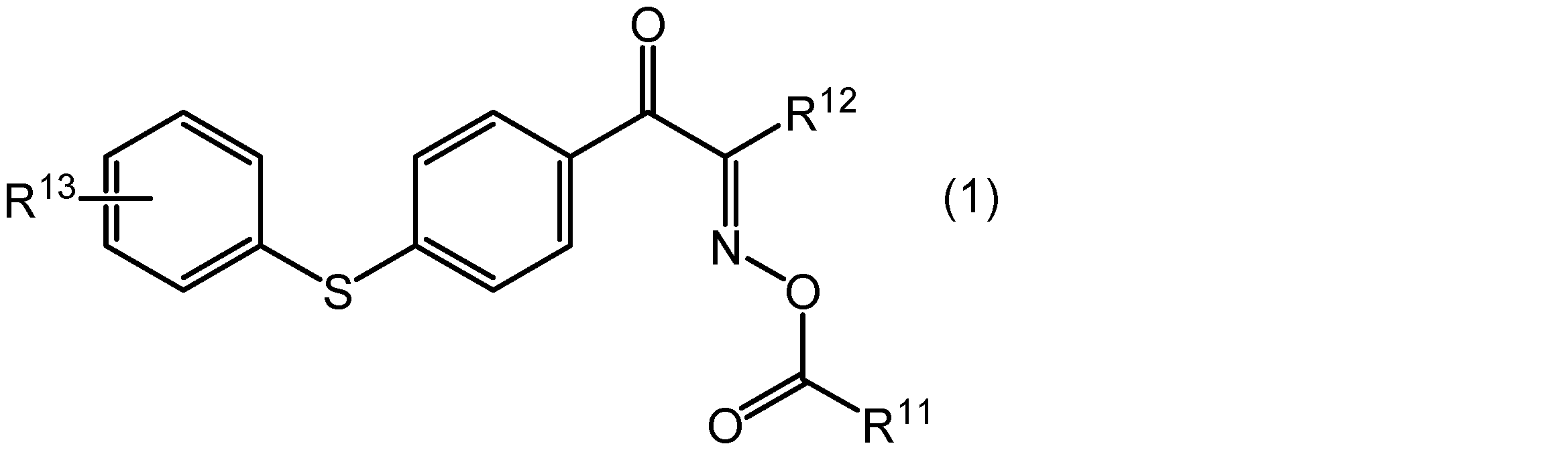
式(1)中、R11及びR12は、それぞれ独立に、炭素数1~12のアルキル基、炭素数4~10のシクロアルキル基、フェニル基又はトリル基を示し、炭素数1~8のアルキル基、炭素数4~6のシクロアルキル基、フェニル基又はトリル基であることが好ましく、炭素数1~4のアルキル基、炭素数4~6のシクロアルキル基、フェニル基又はトリル基であることがより好ましく、メチル基、シクロペンチル基、フェニル基又はトリル基であることが更に好ましい。R13は、-H、-OH、-COOH、-O(CH2)OH、-O(CH2)2OH、-COO(CH2)OH又は-COO(CH2)2OHを示し、-H、-O(CH2)OH、-O(CH2)2OH、-COO(CH2)OH、又は-COO(CH2)2OHであることが好ましく、-H、-O(CH2)2OH、又は-COO(CH2)2OHであることがより好ましい。
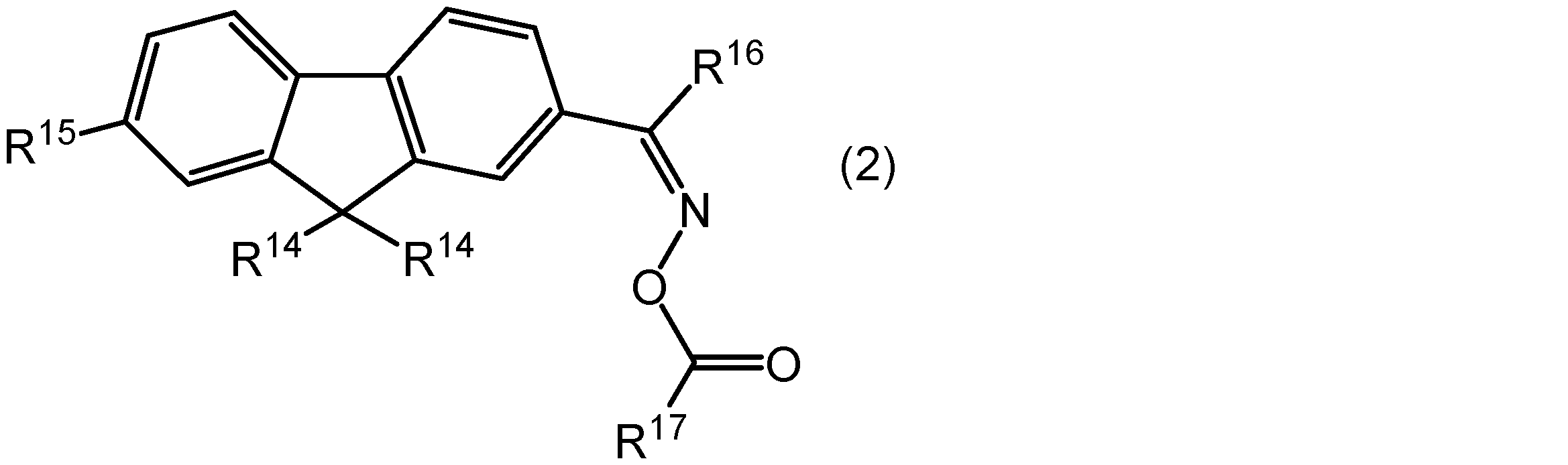
式(2)中、2つのR14は、それぞれ独立に、炭素数1~6のアルキル基を示し、プロピル基であることが好ましい。R15は、NO2又はArCO(ここで、Arはアリール基を示す。)を示し、Arとしては、トリル基が好ましい。R16及びR17は、それぞれ独立に、炭素数1~12のアルキル基、フェニル基、又はトリル基を示し、メチル基、フェニル基又はトリル基であることが好ましい。

式(3)中、R18は、炭素数1~6のアルキル基を示し、エチル基であることが好ましい。R19はアセタール結合を有する有機基であり、後述する市販品の化合物が有するR19に対応する置換基であることが好ましい。R20及びR21は、それぞれ独立に、炭素数1~12のアルキル基、フェニル基又はトリル基を示し、メチル基、フェニル基又はトリル基であることが好ましく、メチル基であることがより好ましい。R22は、水素原子又はアルキル基を示す。
上記一般式(1)で表される化合物としては、IRGACURE OXE 01(BASFジャパン株式会社製、製品名)、又はアデカクルーズNCI-930(株式会社ADEKA製、商品名)として入手可能である。
上記一般式(2)で表される化合物としては、DFI-091、又はDFI-020(ダイトーケミックス株式会社製、製品名)として入手可能である。
上記一般式(3)で表される化合物としては、アデカオプトマーN-1919(株式会社ADEKA製、製品名)、又はIRGACURE OXE 02(BASFジャパン株式会社製、製品名)として入手可能である。
(C)成分の含有量は、光感度及び解像度に優れる点では、(A)成分及び(B)成分の合計量100質量部に対し、0.1~10質量部であることが好ましく、1~8質量部であることがより好ましく、1~6質量部であることが更に好ましく、1~4質量部であることが特に好ましい。
本実施形態に係る感光性樹脂層を形成する感光性樹脂組成物には、添加剤として、必要に応じて、(D)重合禁止剤(以下、(D)成分という場合もある)、(E)レベリング剤(以下、(E)成分という場合もある)、(F)防錆剤(以下、(F)成分という場合もある)、(G)密着助剤(以下、(G)成分という場合もある)などを(A)成分及び(B)成分の合計量100質量部に対し、各々0.01~20質量部程度含有させることができる。これらは、単独で又は2種類以上を組み合わせて使用できる。
感光性樹脂層は、波長400~700nmの可視光領域における全光線透過率が85%以上であることが好ましく、90%以上であることがより好ましく、95%以上であることが更に好ましい。なお、可視光領域における全光線透過率は、本明細書の実施例に記載した方法で測定することができる。
感光性樹脂層は、硬化後における樹脂硬化膜が上記全光線透過率を有していることが好ましい。
また、感光性樹脂層は、CIELAB表色系でのb*が-0.2~1.0であることが好ましく、0.0~0.7であることがより好ましく、0.1~0.4であることが更に好ましい。なお、CIELAB表色系でのb*は、本明細書の実施例に記載した方法で測定することができる。
感光性樹脂層は、硬化後における樹脂硬化膜が上記b*を有していることが好ましい。
感光性樹脂層の厚みは、乾燥後の厚みで2.5μm以下とすることができ、信頼性の確保とセンシング感度の向上の観点から、0.5μm以上2.0μm以下であることがより好ましく、0.6μm以上1.4μm以下であることが更に好ましいく、0.8μm以上1.2μm以下であることが特に好ましい。
感光性樹脂層3は、硬化後の感光性樹脂層の中間層と接する側の表面S1における水に対する接触角が60~90°であることが好ましい。感光性樹脂層がこのような特性を有していると、中間層の現像性を充分確保しつつ、保護フィルムを剥離するときに感光性樹脂層が保護フィルムとともに剥離することを抑制することが容易となる。本実施形態の感光性フィルムが保護フィルムなしに巻回されている場合には、感光性フィルムを引き出すときに感光性樹脂層が隣接する支持フィルム側に剥離することを抑制できる。前述の不具合防止の観点から、上記接触角は、62~88°であることがより好ましく、64~86°であることが更に好ましい。なお、上記の接触角は、本明細書の実施例に記載した接触角2の測定方法により、測定することができる。
また、上記と同様の観点から、感光性樹脂層は、硬化後の感光性樹脂層の中間層と接する側とは反対側の表面における水に対する接触角が60~90°であることが好ましく、62~88°であることがより好ましく、64~86°であることが更に好ましい。なお、この接触角は、本明細書の実施例に記載した接触角1の測定方法により、測定することができる。
更に、上記と同様の観点から、感光性樹脂層を構成する感光性樹脂組成物は、フィルム状に成膜したときの膜表面における水に対する接触角が60~90°であることが好ましく、62~88°であることがより好ましく、64~86°であることが更に好ましい。なお、この接触角は、温度25℃において、膜の表面に1mLの水を滴下し、このときの接触角を接触角計で測定することにより求められる。
感光性樹脂層の水に対する接触角を上述した範囲に調整するには、例えば、(i)バインダーポリマを構成するコモノマー成分における親水成分(例えば親水性基など)と疎水成分(例えば疎水性基など)との割合を調整する方法、(ii)光重合性化合物における親水成分(例えば親水性基など)と疎水成分(例えば疎水性基など)との割合を調整する方法などが挙げられる。
硬化後の感光性樹脂層のヘーズ値は、バイオセンサ等に用いられる誘電泳動電極が設けられた基板等においてセンシング感度を向上させる観点から、0.01~1.0%であることが好ましく、0.01~0.50%であることがより好ましく、0.01~0.30%であることがさらに好ましく、0.01~0.25%であることが特に好ましい。硬化後の感光性樹脂層のヘーズ値は、例えば、厚さ1.0mmのポリカーボネート(PC)基板に感光性樹脂層及び中間層を転写し、所定の条件で露光した後、中間層を除去することにより得られるPC基板/硬化膜の積層体について、硬化膜側から測定して得られる値から求められる。
保護フィルム4(カバーフィルム)としては、重合体フィルムを用いることができる。重合体フィルムとしては、例えば、ポリエチレン、ポリプロピレン、ポリエチレンテレフタレート、ポリカーボネート、ポリエチレン-酢酸ビニル共重合体等からなるフィルム、及びポリエチレン-酢酸ビニル共重合体とポリエチレンとの積層フィルムなどが挙げられる。
保護フィルム4の厚さは、5~100μm程度が好ましいが、ロール状に巻いて保管する観点から、70μm以下であることが好ましく、60μm以下であることがより好ましく、50μm以下であることが更に好ましく、40μm以下であることが特に好ましい。
感光性フィルム10は、ロール状に巻いて保管し、あるいは使用できる。
本実施形態の感光性フィルムは、支持フィルム1上に中間層形成用塗布液を塗布、乾燥し、その後、中間層2上に、感光性樹脂層形成用塗布液を塗布、乾燥し、形成された感光性樹脂層3上に、保護フィルム40を貼り付けることにより形成することができる。また、別の方法として、中間層形成用塗布液及び感光性樹脂層形成用塗布液を調製し、これを各々支持フィルム1、保護フィルム4上に塗布、乾燥することで得られる中間層が形成された支持フィルムと、感光性樹脂層が形成された保護フィルムとを、中間層と感光性樹脂層とが対向した状態で貼り合わせることにより感光性フィルムを形成することもできる。
中間層形成用塗布液及び感光性樹脂層形成用塗布液はそれぞれ、上述した中間層に含まれる成分及び感光性樹脂層に含まれる成分を溶媒に均一に溶解又は分散させることより調製できる。
溶媒としては、特に制限はなく、公知のものが使用でき、例えば、アセトン、メチルエチルケトン、メチルイソブチルケトン、トルエン、メタノール、エタノール、プロパノール、ブタノール、メチレングリコール、エチレングリコール、プロピレングリコール、エチレングリコールモノメチルエーテル、エチレングリコールモノエチルエーテル、ジエチレングリコールジメチルエーテル、ジエチレングリコールエチルメチルエーテル、ジエチレングリコールジエチルエーテル、プロピレングリコールモノメチルエーテル、エチレングリコールモノブチルエーテルアセテート、ジエチレングリコールモノエチルエーテルアセテート、プロピレングリコールモノメチルエーテルアセテート、クロロホルム、塩化メチレンが挙げられる。これら溶媒は、1種を単独で用いてもよいし、2種以上の溶媒からなる混合溶媒として用いてもよい。
塗布方法としては、例えば、ドクターブレードコーティング法、マイヤーバーコーティング法、ロールコーティング法、スクリーンコーティング法、スピナーコーティング法、インクジェットコーティング法、スプレーコーティング法、ディップコーティング法、グラビアコーティング法、カーテンコーティング法、及びダイコーティング法が挙げられる。
乾燥条件に特に制限はないが、乾燥温度は、60~130℃とすることが好ましく、乾燥時間は、0.5~30分とすることが好ましい。
中間層が形成された支持フィルムと、感光性樹脂層が形成された保護フィルムとの貼り合わせは、例えば、ラミネータを用い、ヒートロールの温度20~80℃、圧力0.2~0.8MPa、ロール速度0.2~4.0m/分の条件で行うことができる。
<樹脂硬化膜の形成方法>
図2及び図3は、本実施形態に係る樹脂硬化膜の形成方法を説明するための模式断面図である。本実施形態の樹脂硬化膜の形成方法は、一主面上に段差22を有する基材20(段差付基材24)上に、上述した本実施形態の転写型感光性フィルム10を、保護フィルム4を剥離しながら又は剥離してから感光性樹脂層3が段差22を被覆するようにラミネートする工程S1(図2の(a)及び(b)を参照)と、基材上の感光性樹脂層3の所定部分に光Lを照射する工程S2(図3の(a)を参照)と、感光性樹脂層3及び中間層2に、支持フィルムが除去された状態の中間層2側から現像液を接触させることにより、感光性樹脂層3の所定部分以外及び中間層2を除去し、段差22を被覆する樹脂硬化膜5を形成する工程S3(図3の(b)を参照)とを備える。こうして、樹脂硬化膜付基材40が得られる。
図2及び図3は、本実施形態に係る樹脂硬化膜の形成方法を説明するための模式断面図である。本実施形態の樹脂硬化膜の形成方法は、一主面上に段差22を有する基材20(段差付基材24)上に、上述した本実施形態の転写型感光性フィルム10を、保護フィルム4を剥離しながら又は剥離してから感光性樹脂層3が段差22を被覆するようにラミネートする工程S1(図2の(a)及び(b)を参照)と、基材上の感光性樹脂層3の所定部分に光Lを照射する工程S2(図3の(a)を参照)と、感光性樹脂層3及び中間層2に、支持フィルムが除去された状態の中間層2側から現像液を接触させることにより、感光性樹脂層3の所定部分以外及び中間層2を除去し、段差22を被覆する樹脂硬化膜5を形成する工程S3(図3の(b)を参照)とを備える。こうして、樹脂硬化膜付基材40が得られる。
基材20としては、ポリエチレンテレフタレート、ポリカーボネートなどが挙げられる。
段差22としては、ITO等の透明電極、銅、銅/ニッケル合金、金、白金、ルテニウム、パラジウム、ロジウム、銀、アルミニウム、ニッケル、クロム、亜鉛、錫などの配線若しくは前記金属材料を含む誘電泳動電極、及び光センサなどに起因するものが挙げられる。これらは、2種以上設けられていてもよく、2つ以上設けられていてもよい。
段差付基材24としては、バイオセンサ等に用いられる誘電泳動電極が設けられた基板、光センサ基板、タッチパネル用タッチセンサ基板などが挙げられる。
本実施形態の工程S1におけるラミネート手段としては、圧着ロールが挙げられる。圧着ロールは、加熱圧着できるように加熱手段を備えたものであってもよい。
加熱圧着する場合の加熱温度は、感光性樹脂層と基材との密着性、並びに、段差への追従性を得る観点から、感光性樹脂層の構成成分が熱硬化あるいは熱分解されにくいよう、10~180℃とすることが好ましく、20~160℃とすることがより好ましく、30~150℃とすることが更に好ましい。
また、加熱圧着時の圧着圧力は、密着性確保の観点から、線圧で50~1×10⁵N/mとすることが好ましく、2.5×102~5×104N/mとすることがより好ましく、5×102~4×104N/mとすることが更に好ましい。
感光性フィルムを上記のように加熱すれば、基材を予熱処理することは必要ではないが、感光性樹脂層と基材との密着性を更に向上させる点から、基材を予熱処理することが好ましい。このときの予熱温度は、30~180℃とすることが好ましい。
本実施形態の工程S2では、感光性樹脂層の所定部分に、フォトマスク30を介して、光(活性光線)Lをパターン状に照射する(図3の(a)を参照)。
活性光線を照射する際、中間層上の支持フィルムが透明の場合にはそのまま(例えば、支持フィルムとして透明な重合体フィルムを用いる場合には重合体フィルムを残存させたまま)活性光線を照射することができ、不透明の場合には除去してから活性光線を照射することができる。
光の照射に用いられる活性光線の光源としては、公知の活性光源が使用でき、例えば、カーボンアーク灯、超高圧水銀灯、高圧水銀灯、キセノンランプ等が挙げられ、紫外線を有効に放射するものを好適に用いることができる。
このときの、活性光線Lの照射量は、通常、1×10²~1×10⁴J/m2であり、照射の際に、加熱を伴うこともできる。この活性光線照射量が、上記範囲内であれば、充分な光硬化と、感光性樹脂層が変色することを抑制することとを両立しやすくなる。
本実施形態の工程S3では、活性光線の照射後の感光性樹脂層と中間層とを現像液で現像して、感光性樹脂層の活性光線が照射されていない部分(すなわち、感光性樹脂層の所定部分以外)及び中間層を除去し、段差を被覆する樹脂硬化膜5を形成する(図3の(b)を参照)。形成される樹脂硬化膜5は所定のパターンを有することができる。
なお、活性光線の照射後、中間層上に支持フィルムが積層されている場合にはそれを除去した後、活性光線が照射されていない部分を現像液により除去する現像が行われる。
現像方法としては、アルカリ水溶液、水系現像液、有機溶剤等の公知の現像液を用いて、スプレー、シャワー、揺動浸漬、ブラッシング、スクラッビング等の公知の方法により現像を行い、不要部を除去する方法などが挙げられ、中でも、環境、安全性の観点からアルカリ水溶液を用いるアルカリ現像が好ましいものとして挙げられる。
アルカリ水溶液の塩基としては、水酸化アルカリ(リチウム、ナトリウム又はカリウムの水酸化物等)、炭酸アルカリ(リチウム、ナトリウム又はカリウムの炭酸塩若しくは重炭酸塩等)、アルカリ金属リン酸塩(リン酸カリウム、リン酸ナトリウム等)、アルカリ金属ピロリン酸塩(ピロリン酸ナトリウム、ピロリン酸カリウム等)、水酸化テトラメチルアンモニウム、トリエタノールアミンなどが挙げられ、中でも、水酸化テトラメチルアンモニウム等が好ましいものとして挙げられる。
また、炭酸ナトリウムの水溶液も好ましく用いられ、例えば、20~50℃の炭酸ナトリウムの希薄溶液(0.5~5質量%水溶液)が好適に用いられる。
現像温度及び時間は、本実施形態の感光性樹脂層及び中間層の現像性に合わせて調整することができる。
また、アルカリ水溶液中には、界面活性剤、消泡剤、現像を促進させるための少量の有機溶剤等を混入させることができる。
また、現像後、光硬化後の感光性樹脂層に残存したアルカリ水溶液の塩基を、有機酸、無機酸又はこれらの酸水溶液を用いて、スプレー、揺動浸漬、ブラッシング、スクラッビング等の公知方法により酸処理(中和処理)することができる。
さらに、酸処理(中和処理)の後、水洗する工程を行うこともできる。
現像後、必要に応じて、活性光線の照射(例えば、5×10³~2×10⁴J/m2)により、樹脂硬化膜パターンを更に硬化させてもよい。また、必要に応じて、現像後の活性光線の照射の代わりに、又は活性光線の照射と合わせて、加熱処理(80~250℃)を施してもよい。
上述した本実施形態の樹脂硬化膜の形成方法は、樹脂硬化膜付センサ基板を製造する方法として利用することができる。すなわち、段差付基材24として、一主面上に透明電極及び/又は配線を有する基板(例えば、タッチセンサ基板)、又は、誘電泳動電極を有する基板(例えば、バイオセンサ基板)を用意し、上記と同様の工程を経ることにより、透明電極及び/又は配線、又は誘電泳動電極を被覆する樹脂硬化膜が設けられた樹脂硬化膜付センサ基板を得ることができる。
誘電泳動電極を備える樹脂硬化膜付センサ基板は、樹脂硬化膜を誘電膜としても機能させることができ、液体試料に触れる可能性がある装置(例えば、微生物測定装置)等に適用することができる。
また、段差付基材が一主面上に光学センサを有する光学センサ基板である場合、センサの損傷又は劣化を防ぐための保護膜としてセンサの光学特性への影響が充分に少ない樹脂硬化膜を設けることができる。このような樹脂硬化膜付センサ基板は、水分などによる汚染の可能性がある装置(例えば、食品用検査装置)等に適用することができる。
以下、実施例及び比較例によって、本発明をさらに具体的に説明するが、本発明は以下の実施例に限定されるものではない。
[バインダーポリマー溶液の作製]
(バインダーポリマー溶液A1)
撹拌機、還流冷却器、不活性ガス導入口及び温度計を備えたフラスコに、表1に示す(1)を仕込み、窒素ガス雰囲気下で80℃に昇温した。反応温度を80℃±2℃に保ちながら、表1に示す(2)を4時間かけて均一に滴下した。(2)の滴下後、80℃±2℃で6時間撹拌を続け、重量平均分子量が45000のバインダーポリマーの溶液(固形分50質量%)(A1)を得た。バインダーポリマーの酸価は、114.2mgKOH/gであった。また、ガラス転移温度(Tg)は60℃であった。
(バインダーポリマー溶液A1)
撹拌機、還流冷却器、不活性ガス導入口及び温度計を備えたフラスコに、表1に示す(1)を仕込み、窒素ガス雰囲気下で80℃に昇温した。反応温度を80℃±2℃に保ちながら、表1に示す(2)を4時間かけて均一に滴下した。(2)の滴下後、80℃±2℃で6時間撹拌を続け、重量平均分子量が45000のバインダーポリマーの溶液(固形分50質量%)(A1)を得た。バインダーポリマーの酸価は、114.2mgKOH/gであった。また、ガラス転移温度(Tg)は60℃であった。
(バインダーポリマー溶液A2~A6)
配合量を表1の通りに変えた以外はバインダーポリマー溶液A1と同様にして、バインダーポリマー溶液A2~A6をそれぞれ得た。バインダーポリマーの重量平均分子量、酸価及びTgを表1に示す。
配合量を表1の通りに変えた以外はバインダーポリマー溶液A1と同様にして、バインダーポリマー溶液A2~A6をそれぞれ得た。バインダーポリマーの重量平均分子量、酸価及びTgを表1に示す。

バインダーポリマーの重量平均分子量、酸価及びガラス転移温度は、以下の測定方法で求めた。
1.重量平均分子量の測定
重量平均分子量(Mw)は、ゲルパーミエーションクロマトグラフィー法(GPC)によって測定し、標準ポリスチレンの検量線を用いて換算することにより導出した。GPCの測定条件を以下に示す。
<GPC測定条件>
ポンプ:日立 L-6000型(株式会社日立製作所製、製品名)
カラム:Gelpack GL-R420、Gelpack GL-R430、Gelpack GL-R440(以上、日立化成株式会社製、製品名)
溶離液:テトラヒドロフラン
測定温度:40℃
試料濃度:NV(不揮発分濃度)50質量%の樹脂溶液を120mg採取、5mLのTHFに溶解
注入量:200μL
流量:2.05mL/分
検出器:日立 L-3300型RI(株式会社日立製作所製、製品名)
重量平均分子量(Mw)は、ゲルパーミエーションクロマトグラフィー法(GPC)によって測定し、標準ポリスチレンの検量線を用いて換算することにより導出した。GPCの測定条件を以下に示す。
<GPC測定条件>
ポンプ:日立 L-6000型(株式会社日立製作所製、製品名)
カラム:Gelpack GL-R420、Gelpack GL-R430、Gelpack GL-R440(以上、日立化成株式会社製、製品名)
溶離液:テトラヒドロフラン
測定温度:40℃
試料濃度:NV(不揮発分濃度)50質量%の樹脂溶液を120mg採取、5mLのTHFに溶解
注入量:200μL
流量:2.05mL/分
検出器:日立 L-3300型RI(株式会社日立製作所製、製品名)
2.酸価の測定
酸価は下記に示すような、JIS K0070に基づいた中和滴定法により測定した。まず、バインダーポリマーの溶液を、130℃で1時間加熱し、揮発分を除去して、固形分を得た。そして、この固形分のポリマー1.0gを精秤した後、このポリマーにアセトンを30g添加し、これを均一に溶解し、樹脂溶液を得た。次いで、指示薬であるフェノールフタレインをその樹脂溶液に適量添加して、0.1mol/Lの水酸化カリウム水溶液を用いて滴定を行った。そして、次式により酸価を算出した。
酸価=0.1×V×f1×56.1/(Wp×I/100)
式中、Vは滴定に用いた0.1mol/Lの水酸化カリウム水溶液の滴定量(mL)を示し、f1は0.1mol/Lの水酸化カリウム水溶液のファクター(濃度換算係数)を示し、Wpは測定した樹脂溶液の質量(g)を示し、Iは測定した上記樹脂溶液中の不揮発分の割合(質量%)を示す。
酸価は下記に示すような、JIS K0070に基づいた中和滴定法により測定した。まず、バインダーポリマーの溶液を、130℃で1時間加熱し、揮発分を除去して、固形分を得た。そして、この固形分のポリマー1.0gを精秤した後、このポリマーにアセトンを30g添加し、これを均一に溶解し、樹脂溶液を得た。次いで、指示薬であるフェノールフタレインをその樹脂溶液に適量添加して、0.1mol/Lの水酸化カリウム水溶液を用いて滴定を行った。そして、次式により酸価を算出した。
酸価=0.1×V×f1×56.1/(Wp×I/100)
式中、Vは滴定に用いた0.1mol/Lの水酸化カリウム水溶液の滴定量(mL)を示し、f1は0.1mol/Lの水酸化カリウム水溶液のファクター(濃度換算係数)を示し、Wpは測定した樹脂溶液の質量(g)を示し、Iは測定した上記樹脂溶液中の不揮発分の割合(質量%)を示す。
3.ガラス転移温度(Tg)の測定
バインダーポリマー溶液をポリエチレンテレフタレートフィルム(帝人デュポンフィルム株式会社製、製品名「ピューレックスA53」)上に均一に塗布し、90℃の熱風対流式乾燥機で10分間乾燥して、乾燥後の厚みが40μmであるバインダーポリマーからなる膜を形成した。次いで高圧水銀ランプを有する露光機(株式会社オーク製作所製、商品名「EXM-1201」)を用いて、照射エネルギー量が400mJ/cm2(i線(波長365nm)における測定値)となるように上記膜を露光した。露光された膜をホットプレート上にて65℃で2分間、次いで95℃で8分間加熱し、熱風対流式乾燥機にて180℃で60分間加熱処理をした。形成された硬化膜を、ポリエチレンテレフタレートフィルムから剥離し、セイコーインスツルメンツ社製TMA/SS6000を用いて、昇温速度5℃/分で温度を上昇させたときの上記硬化膜の熱膨張率を測定し、その曲線から得られる変曲点をガラス転移温度Tgとして求めた。
バインダーポリマー溶液をポリエチレンテレフタレートフィルム(帝人デュポンフィルム株式会社製、製品名「ピューレックスA53」)上に均一に塗布し、90℃の熱風対流式乾燥機で10分間乾燥して、乾燥後の厚みが40μmであるバインダーポリマーからなる膜を形成した。次いで高圧水銀ランプを有する露光機(株式会社オーク製作所製、商品名「EXM-1201」)を用いて、照射エネルギー量が400mJ/cm2(i線(波長365nm)における測定値)となるように上記膜を露光した。露光された膜をホットプレート上にて65℃で2分間、次いで95℃で8分間加熱し、熱風対流式乾燥機にて180℃で60分間加熱処理をした。形成された硬化膜を、ポリエチレンテレフタレートフィルムから剥離し、セイコーインスツルメンツ社製TMA/SS6000を用いて、昇温速度5℃/分で温度を上昇させたときの上記硬化膜の熱膨張率を測定し、その曲線から得られる変曲点をガラス転移温度Tgとして求めた。
[中間層形成用塗布液の調製]
ポリビニルアルコール(固形分13.5質量%)(大成化薬株式会社製、製品名:マルタイトHC-100G)、ポリビニルピロリドン(株式会社日本触媒製、製品名:K-30)、レベリング剤(共栄社化学株式会社製、WS-314)、イソプロピルアルコール(特級)(和光純薬工業株式会社製)、及び精製水を表2に示す割合で混合することにより、中間層形成用塗布液を得た。
ポリビニルアルコール(固形分13.5質量%)(大成化薬株式会社製、製品名:マルタイトHC-100G)、ポリビニルピロリドン(株式会社日本触媒製、製品名:K-30)、レベリング剤(共栄社化学株式会社製、WS-314)、イソプロピルアルコール(特級)(和光純薬工業株式会社製)、及び精製水を表2に示す割合で混合することにより、中間層形成用塗布液を得た。

[感光性樹脂層形成用塗布液の調製]
表3に示す各成分を同表に示す量(単位:質量部)で混合することにより、感光性樹脂層を形成するための感光性樹脂組成物を含有する感光性樹脂層形成用塗布液R1~R10をそれぞれ調製した。なお、表3中の溶剤以外の配合量は、いずれも固形分での配合量である。
表3に示す各成分を同表に示す量(単位:質量部)で混合することにより、感光性樹脂層を形成するための感光性樹脂組成物を含有する感光性樹脂層形成用塗布液R1~R10をそれぞれ調製した。なお、表3中の溶剤以外の配合量は、いずれも固形分での配合量である。

表3中の成分の記号は以下の意味を示す。
(A)成分
A1:上記で得られたバインダーポリマー溶液A1
A2:上記で得られたバインダーポリマー溶液A2
A3:上記で得られたバインダーポリマー溶液A3
A4:上記で得られたバインダーポリマー溶液A4
A5:上記で得られたバインダーポリマー溶液A5
A6:上記で得られたバインダーポリマー溶液A6
(A)成分
A1:上記で得られたバインダーポリマー溶液A1
A2:上記で得られたバインダーポリマー溶液A2
A3:上記で得られたバインダーポリマー溶液A3
A4:上記で得られたバインダーポリマー溶液A4
A5:上記で得られたバインダーポリマー溶液A5
A6:上記で得られたバインダーポリマー溶液A6
(B)成分
A-TMMT:ペンタエリスリトールテトラアクリレート(新中村化学工業株式会社製、製品名「A-TMMT」)
A-DCP:トリシクロデカンジメタノールジアクリレート(新中村化学工業株式会社製、製品名「A-DCP」)
BPE-100:エトキシ化ビスフェノールAジメタクリレート(新中村化学工業株式会社製、製品名「BPE-100」)
A-TMMT:ペンタエリスリトールテトラアクリレート(新中村化学工業株式会社製、製品名「A-TMMT」)
A-DCP:トリシクロデカンジメタノールジアクリレート(新中村化学工業株式会社製、製品名「A-DCP」)
BPE-100:エトキシ化ビスフェノールAジメタクリレート(新中村化学工業株式会社製、製品名「BPE-100」)
(C)成分
OXE-01:1,2-オクタンジオン,1-[4-(フェニルチオ)フェニル-,2-(O-ベンゾイルオキシム)](BASFジャパン株式会社製、製品名「IRGACURE OXE 01」)
OXE-01:1,2-オクタンジオン,1-[4-(フェニルチオ)フェニル-,2-(O-ベンゾイルオキシム)](BASFジャパン株式会社製、製品名「IRGACURE OXE 01」)
(D)成分
Antage W-500:2,2’-メチレン-ビス(4-エチル-6-tert-ブチルフェノール)(川口化学工業株式会社製、製品名「Antage W-500」)
Antage W-500:2,2’-メチレン-ビス(4-エチル-6-tert-ブチルフェノール)(川口化学工業株式会社製、製品名「Antage W-500」)
(E)成分
Additive8032:有機変性シリコーンオイル(東レダウコーニング株式会社製、製品名「Additive8032」)
Additive8032:有機変性シリコーンオイル(東レダウコーニング株式会社製、製品名「Additive8032」)
(F)成分
チオエールB-6030:テトラゾール(固形分5質量%)(千代田ケミカル株式会社製、製品名「チオエールB-6030」)
チオエールB-6030:テトラゾール(固形分5質量%)(千代田ケミカル株式会社製、製品名「チオエールB-6030」)
(G)成分
PM-21:2-ヒドロキシエチルメタクリレートの6-ヘキサノリド付加重合物と無水リン酸との反応生成物(日本化薬株式会社社製、製品名「PM-21」)
PM-21:2-ヒドロキシエチルメタクリレートの6-ヘキサノリド付加重合物と無水リン酸との反応生成物(日本化薬株式会社社製、製品名「PM-21」)
溶媒
MEK:メチルエチルケトン(東燃化学合同会社製)
MEK:メチルエチルケトン(東燃化学合同会社製)
[転写型感光性フィルムの作製]
<中間層の形成>
支持フィルムとして厚さ16μmのポリエチレンテレフタレートフィルムを用意し、上記で調製した中間層形成用塗布液を支持フィルム上にバーコーターを用いて均一に塗布し、80℃の熱風対流式乾燥機で20分間乾燥し、乾燥後の厚みが3、5、10、15、30μmである中間層をそれぞれ形成した。
<中間層の形成>
支持フィルムとして厚さ16μmのポリエチレンテレフタレートフィルムを用意し、上記で調製した中間層形成用塗布液を支持フィルム上にバーコーターを用いて均一に塗布し、80℃の熱風対流式乾燥機で20分間乾燥し、乾燥後の厚みが3、5、10、15、30μmである中間層をそれぞれ形成した。
<感光性樹脂層の形成>
(実施例1~12及び比較例1、2)
上記で形成された中間層のうち、表4~6に示される厚みを有する中間層上に、表4~6に示される感光性樹脂層形成用塗布液を、バーコーターを用いて均一に塗布し、80℃のホットプレートで5分間乾燥し、乾燥後の厚みが1μmである感光性樹脂層を形成した。
(実施例1~12及び比較例1、2)
上記で形成された中間層のうち、表4~6に示される厚みを有する中間層上に、表4~6に示される感光性樹脂層形成用塗布液を、バーコーターを用いて均一に塗布し、80℃のホットプレートで5分間乾燥し、乾燥後の厚みが1μmである感光性樹脂層を形成した。
次いで、形成された感光性樹脂層の上に、保護フィルムとしてポリプロピレンフィルムを貼り合わせて、支持フィルムと、中間層と、感光性樹脂層と、保護フィルムとがこの順に積層された感光性フィルムを得た。
(比較例3及び4)
比較例3及び4については、中間層を設けないため、支持フィルムとして用意した厚さ16μmのポリエチレンテレフタレートフィルム上に、表6に示される感光性樹脂層形成用塗布液をバーコーターを用いて均一に塗布し、80℃のホットプレートで20分間乾燥し、乾燥後の厚みが1μm(比較例3)及び3μm(比較例4)の感光性樹脂層を形成した。
比較例3及び4については、中間層を設けないため、支持フィルムとして用意した厚さ16μmのポリエチレンテレフタレートフィルム上に、表6に示される感光性樹脂層形成用塗布液をバーコーターを用いて均一に塗布し、80℃のホットプレートで20分間乾燥し、乾燥後の厚みが1μm(比較例3)及び3μm(比較例4)の感光性樹脂層を形成した。
次いで、形成された感光性樹脂層の上に、保護フィルムとしてポリプロピレンフィルムを貼り合わせて、支持フィルムと、感光性樹脂層と、保護フィルムとがこの順に積層された感光性フィルムを得た。
(実施例13)
保護フィルムとして用意したポリプロピレンフィルム上に、表5に示される感光性樹脂層形成用塗布液を、バーコーターを用いて均一に塗布し、80℃のホットプレートで5分間乾燥し、乾燥後の厚みが1μmである感光性樹脂層を形成した。
保護フィルムとして用意したポリプロピレンフィルム上に、表5に示される感光性樹脂層形成用塗布液を、バーコーターを用いて均一に塗布し、80℃のホットプレートで5分間乾燥し、乾燥後の厚みが1μmである感光性樹脂層を形成した。
次いで、形成された感光性樹脂層の上に、上記で作製された厚み5μmの中間層を貼り合わせて、支持フィルムと、中間層と、感光性樹脂層と、保護フィルムとがこの順に積層された感光性フィルムを得た。なお、貼り合わせは、ラミネータ「MRK-650Y」(株式会社MCK製、製品名)を用い、ヒートロールの温度25℃、圧力0.40MPa、ロール速度0.6m/分の条件で行った。


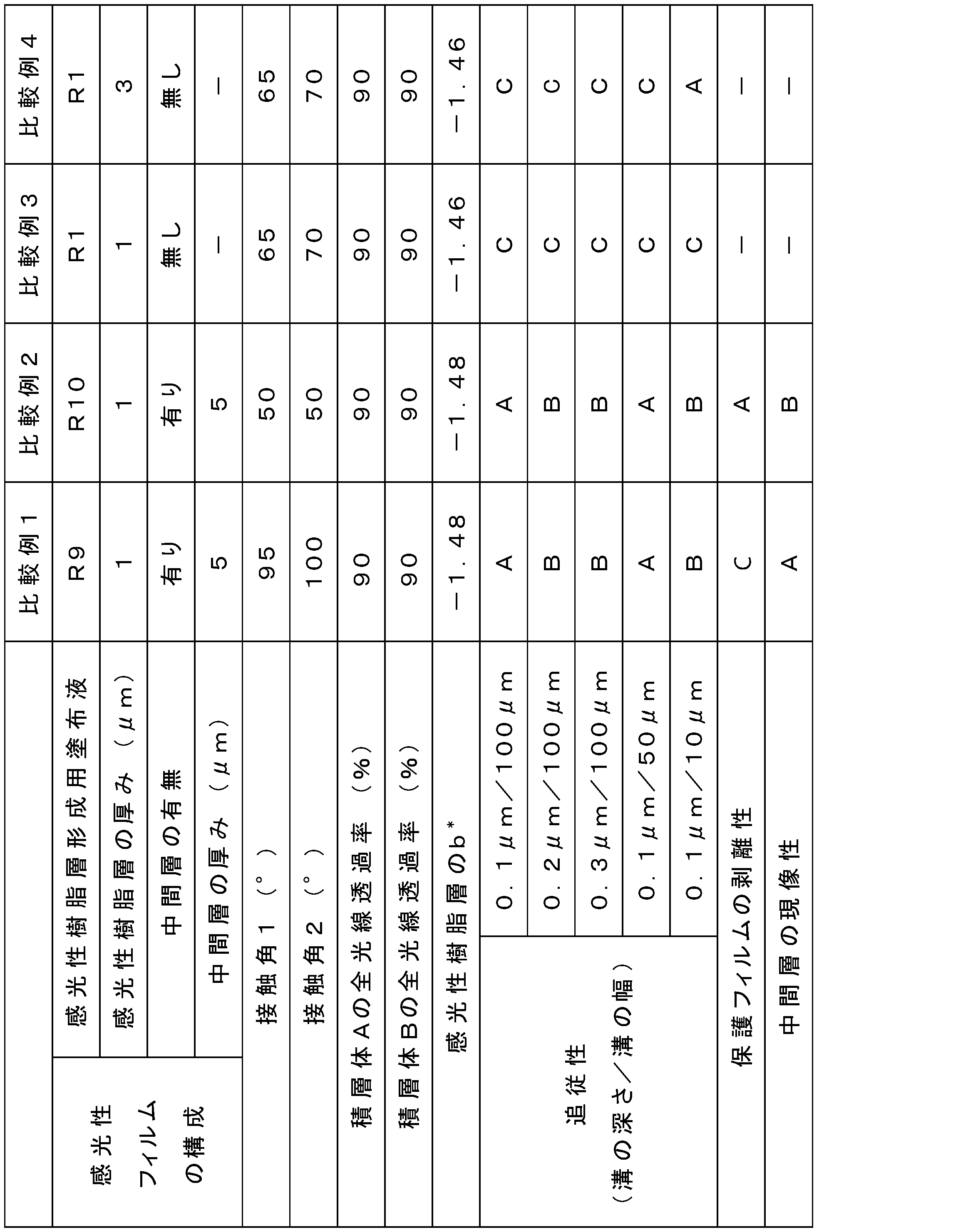
上記で得られた感光性フィルムについて、下記の方法により、保護フィルムの剥離性、中間層の現像性、感光性樹脂層の接触角、追従性、光学特性の評価を行った。
<保護フィルムの剥離性>
感光性フィルムの保護フィルムを手で剥離し、残った感光性樹脂層の状態を目視で観察し、以下の基準で剥離性を評価した。
[判定基準]
A:感光性樹脂層と保護フィルムとが綺麗に剥がれている。
B:感光性樹脂層の一部が剥がれて保護フィルムに残っている。
C:感光性樹脂層が保護フィルムと一緒に剥がれている(中間層と感光性樹脂層との間で剥離が生じた)。
感光性フィルムの保護フィルムを手で剥離し、残った感光性樹脂層の状態を目視で観察し、以下の基準で剥離性を評価した。
[判定基準]
A:感光性樹脂層と保護フィルムとが綺麗に剥がれている。
B:感光性樹脂層の一部が剥がれて保護フィルムに残っている。
C:感光性樹脂層が保護フィルムと一緒に剥がれている(中間層と感光性樹脂層との間で剥離が生じた)。
<評価用積層体の作製>
感光性フィルムの保護フィルムを剥がしながら、ガラス基板(縦6cm×横6cm、厚み1mm)に感光性樹脂層をラミネートした。ラミネートは、ラミネータ「MRK-650Y」(株式会社MCK製、製品名)を用い、ヒートロール温度110℃、圧力0.40MPa、ロール速度0.6m/分の条件で行った。こうして、ガラス基板、感光性樹脂層、中間層及び支持フィルムの順に積層された積層体1を得た。
感光性フィルムの保護フィルムを剥がしながら、ガラス基板(縦6cm×横6cm、厚み1mm)に感光性樹脂層をラミネートした。ラミネートは、ラミネータ「MRK-650Y」(株式会社MCK製、製品名)を用い、ヒートロール温度110℃、圧力0.40MPa、ロール速度0.6m/分の条件で行った。こうして、ガラス基板、感光性樹脂層、中間層及び支持フィルムの順に積層された積層体1を得た。
次いで、上記積層体1に、平行光線露光機「EXM1201」(オーク製作所株式会社製、製品名)を使用して、支持フィルム側から露光量60mJ/cm2(i線(波長365nm)における測定値)で、紫外線を照射した。その後、支持フィルムを剥がし、さらに中間層側から露光量1000mJ/cm2(i線(波長365nm))で紫外線を照射して積層体2を得た。
次いで、露光後の積層体2を、1質量%の炭酸ナトリウム水溶液で現像した。なお、現像は、現像機を用い、スプレー圧0.2MPa、温度30℃、現像時間30秒間の条件で行い、積層体3を得た。
<中間層の現像性>
各感光性フィルムを用いて上記積層体3を作製した。積層体3の樹脂硬化膜上に残った中間層を目視で確認し、下記の基準で中間層の現像性を評価した。
[判定基準]
A:中間層が無い(中間層の現像性が良好)。
B:樹脂硬化膜上の一部に中間層がある(中間層の現像残渣が発生している)。
各感光性フィルムを用いて上記積層体3を作製した。積層体3の樹脂硬化膜上に残った中間層を目視で確認し、下記の基準で中間層の現像性を評価した。
[判定基準]
A:中間層が無い(中間層の現像性が良好)。
B:樹脂硬化膜上の一部に中間層がある(中間層の現像残渣が発生している)。
<接触角の評価>
(接触角1)
各感光性フィルムの支持フィルム側を、ガラス基板(縦6cm×横6cm、厚み1mm)に、両面テープ「ナイスタック 一般タイプ15mm×20m NW-15」(ニチバン社製、製品名)で固定し、積層体4を得た。
(接触角1)
各感光性フィルムの支持フィルム側を、ガラス基板(縦6cm×横6cm、厚み1mm)に、両面テープ「ナイスタック 一般タイプ15mm×20m NW-15」(ニチバン社製、製品名)で固定し、積層体4を得た。
次いで、上記積層体4に、平行光線露光機「EXM1201」(オーク製作所株式会社製、製品名)を使用して、支持フィルム側から露光量60mJ/cm2(i線(波長365nm)における測定値)で、紫外線を照射した。その後、支持フィルムを剥がして、積層体5を作製した。温度25℃において、積層体5の樹脂硬化膜の表面に1mLの水を滴下し、このときの接触角を接触角計で測定した。
(接触角2)
各感光性フィルムを用い、上記の評価用積層体の作製と同様にして積層体3を作製した。温度25℃において、積層体3の樹脂硬化膜の表面に1mLの水を滴下し、このときの接触角を接触角計で測定した。
各感光性フィルムを用い、上記の評価用積層体の作製と同様にして積層体3を作製した。温度25℃において、積層体3の樹脂硬化膜の表面に1mLの水を滴下し、このときの接触角を接触角計で測定した。
<追従性の評価>
下記表7に示されるパターン1~5が形成された銅基板(40mm×20mm)(日立化成株式会社製)を5種類用意した。
下記表7に示されるパターン1~5が形成された銅基板(40mm×20mm)(日立化成株式会社製)を5種類用意した。
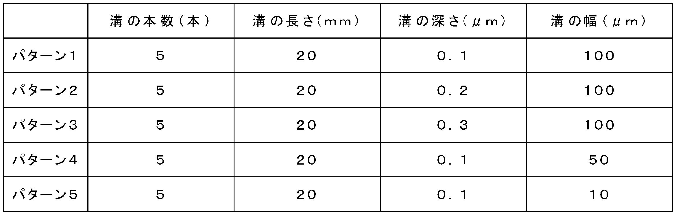
各感光性フィルムの保護フィルムを剥がしながら、上記の銅基板に感光性樹脂層をラミネートした。ラミネートは、ラミネータ「MRK-650Y」(株式会社MCK製、製品名)を用い、ヒートロール温度110℃、圧力0.40MPa、ロール速度0.6m/分の条件で行った。こうして、銅基板、感光性樹脂層、中間層及び支持フィルムの順に積層された積層体6を得た。
積層体6を中間層側から顕微鏡「BX-60」(オリンパス社製)で観察することにより溝部分のラミネートボイド(気泡)数を測定し、下記の基準で追従性を評価した。
[判定基準]
A:溝部分の気泡が0個。
B:溝部分の気泡が1個以上5個以下。
C:溝部分の気泡が6個以上。
[判定基準]
A:溝部分の気泡が0個。
B:溝部分の気泡が1個以上5個以下。
C:溝部分の気泡が6個以上。
<光学特性の評価>
感光性フィルムの保護フィルムを剥がしながら、ポリカーボネート基板(縦6cm×横6cm、厚み1mm、三菱瓦斯化学株式会社製)に感光性樹脂層をラミネートした。ラミネートは、ラミネータ「MRK-650Y」(株式会社MCK製、製品名)を用い、ヒートロール温度110℃、圧力0.40MPa、ロール速度0.6m/分の条件で行った。こうして、ガラス基板、感光性樹脂層、中間層及び支持フィルムの順に積層された積層体Aを得た。
感光性フィルムの保護フィルムを剥がしながら、ポリカーボネート基板(縦6cm×横6cm、厚み1mm、三菱瓦斯化学株式会社製)に感光性樹脂層をラミネートした。ラミネートは、ラミネータ「MRK-650Y」(株式会社MCK製、製品名)を用い、ヒートロール温度110℃、圧力0.40MPa、ロール速度0.6m/分の条件で行った。こうして、ガラス基板、感光性樹脂層、中間層及び支持フィルムの順に積層された積層体Aを得た。
次いで、上記積層体Aに、平行光線露光機「EXM1201」(オーク製作所株式会社製、製品名)を使用して、支持フィルム側から露光量60mJ/cm2(i線(波長365nm)における測定値)で、紫外線を照射した。その後、支持フィルムを剥がし、さらに中間層側から露光量1000mJ/cm2(i線(波長365nm)における測定値)で紫外線を照射した。
次いで、露光後の積層体Aを、1質量%の炭酸ナトリウム水溶液で現像した。なお、現像は、現像機を用い、スプレー圧0.2MPa、温度30℃、現像時間30秒間の条件で行い、積層体Bを得た。
積層体A及び積層体Bについて、濁度計(NDH5000)を使用して、全光線透過率(基材を含む)を測定した。また、積層体Bについて、分光測色計CM-5(コニカミノルタ(株)製)を用い、光源設定D65、視野角2°でCIELAB表色系でのb*を測定した。
表4及び表5に示されるように、実施例1~13の感光性フィルムによれば、段差を有する基材上であってもボイドの発生を充分抑制することができるとともに、感光性樹脂層の剥離及び中間層の現像残渣を充分抑制することができ、薄膜の樹脂硬化膜を良好に形成することが可能であることが分かった。
1…支持フィルム、2…中間層、3…感光性樹脂層、4…保護フィルム、5…樹脂硬膜、10…転写型感光性フィルム、20…基材、22…段差、24…段差付き基材、30…フォトマスク、40…樹脂硬化膜付基材。
Claims (12)
- 支持フィルムと、水溶性高分子を含む中間層と、感光性樹脂層と、がこの順に積層された構造を有し、
前記感光性樹脂層は、厚みが2.5μm以下であり、且つ、硬化後の前記感光性樹脂層の前記中間層と接する側の表面における水に対する接触角が60~90°である、転写型感光性フィルム。 - 前記中間層がポリビニルアルコールを50質量%以上含む、請求項1に記載の転写型感光性フィルム。
- 前記感光性樹脂層は、波長400~700nmの可視光領域における全光線透過率が85%以上である、請求項1又は2に記載の転写型感光性フィルム。
- 前記感光性樹脂層は、CIELAB表色系でのb*が-0.2~1.0である、請求項1~3のいずれか一項に記載の転写型感光性フィルム。
- 前記中間層は、厚みが3~30μmである、請求項1~4のいずれか一項に記載の転写型感光性フィルム。
- バイオセンサ基板上に保護膜を形成するために用いる、請求項1~5のいずれか一項に記載の転写型感光性フィルム。
- 誘電泳動電極を有するバイオセンサ基板の前記誘電泳動電極上に保護膜を形成するために用いる、請求項1~5のいずれか一項に記載の転写型感光性フィルム。
- 一主面上に段差を有する基材上に、請求項1~5のいずれか一項に記載の転写型感光性フィルムを、前記感光性樹脂層が前記段差を被覆するようにラミネートする工程と、
前記基材上の前記感光性樹脂層の所定部分に光を照射する工程と、
前記感光性樹脂層及び前記中間層に、前記支持フィルムが除去された状態の前記中間層側から現像液を接触させることにより、前記感光性樹脂層の前記所定部分以外及び前記中間層を除去し、前記段差を被覆する樹脂硬化膜を形成する工程と、
を備える、樹脂硬化膜の形成方法。 - 前記段差が、前記基材の前記主面上に設けられた透明電極及び/又は配線に起因する段差である、請求項8に記載の樹脂硬化膜の形成方法。
- 前記段差が、前記基材の前記主面上に設けられた誘電泳動電極に起因する段差である、請求項8に記載の樹脂硬化膜の形成方法。
- 一主面上に透明電極及び/又は配線を有する基板上に、請求項1~5のいずれか一項に記載の転写型感光性フィルムを、前記感光性樹脂層が前記透明電極及び/又は前記配線を被覆するようにラミネートする工程と、
前記基板上の前記感光性樹脂層の所定部分に光を照射する工程と、
光照射された前記感光性樹脂層及び前記中間層に、前記支持フィルムが除去された状態の前記中間層側から現像液を接触させることにより、前記感光性樹脂層の前記所定部分以外及び前記中間層を除去し、前記透明電極及び/又は前記配線を被覆する樹脂硬化膜を形成する工程と、
を備える、樹脂硬化膜付センサ基板の製造方法。 - 一主面上に誘電泳動電極を有する基板上に、請求項1~5のいずれか一項に記載の転写型感光性フィルムを、前記感光性樹脂層が前記誘電泳動電極を被覆するようにラミネートする工程と、
前記基板上の前記感光性樹脂層の所定部分に光を照射する工程と、
光照射された前記感光性樹脂層及び前記中間層に、前記支持フィルムが除去された状態の前記中間層側から現像液を接触させることにより、前記感光性樹脂層の前記所定部分以外及び前記中間層を除去し、前記誘電泳動電極を被覆する樹脂硬化膜を形成する工程と、
を備える、樹脂硬化膜付センサ基板の製造方法。
Priority Applications (1)
| Application Number | Priority Date | Filing Date | Title |
|---|---|---|---|
| PCT/JP2018/034290 WO2020054075A1 (ja) | 2018-09-14 | 2018-09-14 | 転写型感光性フィルム、樹脂硬化膜の形成方法及び樹脂硬化膜付センサ基板の製造方法 |
Applications Claiming Priority (1)
| Application Number | Priority Date | Filing Date | Title |
|---|---|---|---|
| PCT/JP2018/034290 WO2020054075A1 (ja) | 2018-09-14 | 2018-09-14 | 転写型感光性フィルム、樹脂硬化膜の形成方法及び樹脂硬化膜付センサ基板の製造方法 |
Publications (1)
| Publication Number | Publication Date |
|---|---|
| WO2020054075A1 true WO2020054075A1 (ja) | 2020-03-19 |
Family
ID=69776504
Family Applications (1)
| Application Number | Title | Priority Date | Filing Date |
|---|---|---|---|
| PCT/JP2018/034290 Ceased WO2020054075A1 (ja) | 2018-09-14 | 2018-09-14 | 転写型感光性フィルム、樹脂硬化膜の形成方法及び樹脂硬化膜付センサ基板の製造方法 |
Country Status (1)
| Country | Link |
|---|---|
| WO (1) | WO2020054075A1 (ja) |
Cited By (1)
| Publication number | Priority date | Publication date | Assignee | Title |
|---|---|---|---|---|
| JPWO2022019046A1 (ja) * | 2020-07-20 | 2022-01-27 |
Citations (6)
| Publication number | Priority date | Publication date | Assignee | Title |
|---|---|---|---|---|
| US6027858A (en) * | 1997-06-06 | 2000-02-22 | International Business Machines Corporation | Process for tenting PTH's with PID dry film |
| JP2006030999A (ja) * | 2005-07-11 | 2006-02-02 | Asahi Kasei Electronics Co Ltd | 感光性樹脂積層体 |
| JP2007327979A (ja) * | 2004-09-01 | 2007-12-20 | Fujifilm Holdings Corp | パターン形成材料、並びにパターン形成装置及びパターン形成方法 |
| WO2009096292A1 (ja) * | 2008-01-29 | 2009-08-06 | Asahi Kasei E-Materials Corporation | 感光性樹脂積層体 |
| JP2013083535A (ja) * | 2011-10-07 | 2013-05-09 | Dainippon Printing Co Ltd | 透明バイオセンサ |
| WO2017209193A1 (ja) * | 2016-05-31 | 2017-12-07 | 富士フイルム株式会社 | 転写フィルム、加飾パターン及びタッチパネル |
-
2018
- 2018-09-14 WO PCT/JP2018/034290 patent/WO2020054075A1/ja not_active Ceased
Patent Citations (6)
| Publication number | Priority date | Publication date | Assignee | Title |
|---|---|---|---|---|
| US6027858A (en) * | 1997-06-06 | 2000-02-22 | International Business Machines Corporation | Process for tenting PTH's with PID dry film |
| JP2007327979A (ja) * | 2004-09-01 | 2007-12-20 | Fujifilm Holdings Corp | パターン形成材料、並びにパターン形成装置及びパターン形成方法 |
| JP2006030999A (ja) * | 2005-07-11 | 2006-02-02 | Asahi Kasei Electronics Co Ltd | 感光性樹脂積層体 |
| WO2009096292A1 (ja) * | 2008-01-29 | 2009-08-06 | Asahi Kasei E-Materials Corporation | 感光性樹脂積層体 |
| JP2013083535A (ja) * | 2011-10-07 | 2013-05-09 | Dainippon Printing Co Ltd | 透明バイオセンサ |
| WO2017209193A1 (ja) * | 2016-05-31 | 2017-12-07 | 富士フイルム株式会社 | 転写フィルム、加飾パターン及びタッチパネル |
Cited By (5)
| Publication number | Priority date | Publication date | Assignee | Title |
|---|---|---|---|---|
| JPWO2022019046A1 (ja) * | 2020-07-20 | 2022-01-27 | ||
| WO2022019046A1 (ja) * | 2020-07-20 | 2022-01-27 | 昭和電工マテリアルズ株式会社 | 感光性エレメント、レジストパターンの形成方法及びプリント配線板の製造方法 |
| KR20230041976A (ko) * | 2020-07-20 | 2023-03-27 | 가부시끼가이샤 레조낙 | 감광성 엘리먼트, 레지스트 패턴의 형성 방법 및 프린트 배선판의 제조 방법 |
| KR102870994B1 (ko) * | 2020-07-20 | 2025-10-16 | 가부시끼가이샤 레조낙 | 감광성 엘리먼트, 레지스트 패턴의 형성 방법 및 프린트 배선판의 제조 방법 |
| TWI902842B (zh) * | 2020-07-20 | 2025-11-01 | 日商力森諾科股份有限公司 | 感光性元件、光阻圖案之形成方法及印刷配線板之製造方法 |
Similar Documents
| Publication | Publication Date | Title |
|---|---|---|
| JP6589953B2 (ja) | 感光性エレメント | |
| CN103975294B (zh) | 触摸面板用电极的保护膜的形成方法、感光性树脂组合物及感光性元件、以及触摸面板的制造方法 | |
| JP6540766B2 (ja) | タッチパネル用電極の保護膜及びタッチパネル | |
| WO2013084873A1 (ja) | タッチパネル用電極の保護膜の形成方法、感光性樹脂組成物及び感光性エレメント、並びに、タッチパネルの製造方法 | |
| JPWO2014196546A1 (ja) | 硬化膜付き透明基材の製造方法、感光性樹脂組成物、感光性エレメント及び電子部品 | |
| JP2013200577A (ja) | 樹脂硬化膜パターンの形成方法、感光性樹脂組成物、感光性エレメント、タッチパネルの製造方法及び樹脂硬化膜 | |
| WO2016181422A1 (ja) | 転写形感光性屈折率調整フィルム、屈折率調整パターンの形成方法及び電子部品 | |
| JP2015014783A (ja) | 硬化膜付き透明基材の製造方法、感光性樹脂組成物、感光性エレメント、及び電子部品 | |
| JPWO2016002026A1 (ja) | 転写形感光性屈折率調整フィルム | |
| WO2014050567A1 (ja) | 感光性樹脂組成物、感光性エレメント、レジストパターンの形成方法及びタッチパネルの製造方法 | |
| WO2020054075A1 (ja) | 転写型感光性フィルム、樹脂硬化膜の形成方法及び樹脂硬化膜付センサ基板の製造方法 | |
| JP2018165788A (ja) | 転写型感光性フィルム、硬化樹脂パターンの形成方法及びタッチパネル | |
| JP2017181541A (ja) | 感光性フィルム、感光性屈折率調整フィルム、屈折率調整パターンの形成方法、硬化膜及び電子部品 | |
| JPWO2017056131A1 (ja) | 転写形感光性屈折率調整フィルム | |
| WO2016132401A1 (ja) | 転写形感光性屈折率調整フィルム、屈折率調整パターンの形成方法及び電子部品 | |
| WO2020261523A1 (ja) | 転写型感光性フィルム、樹脂硬化膜の形成方法及び樹脂硬化膜付基板の製造方法 | |
| JP2018045126A (ja) | 真空ラミネート用感光性フィルム、転写型感光性屈折率調整フィルム、及び硬化樹脂パターンの形成方法 | |
| JP2017198878A (ja) | 感光性導電フィルム及びそれを用いた導電パターン、導電パターン基板、タッチパネルセンサの製造方法 | |
| JP2019095465A (ja) | 感光性屈折率調整フィルム、硬化膜パターンの形成方法、硬化膜及び電子部品 | |
| JP2015146038A (ja) | 樹脂硬化膜パターンの形成方法、感光性樹脂組成物、感光性エレメント、タッチパネルの製造方法及び樹脂硬化膜 | |
| WO2019207648A1 (ja) | 感光性樹脂組成物、転写型感光性フィルム、硬化膜付き基材及びセンシングデバイス | |
| JP6299940B1 (ja) | 感光性エレメント及び感光性エレメントロール | |
| WO2019224887A1 (ja) | 転写型感光性フィルム、樹脂硬化膜付き電極基板及びタッチパネル | |
| WO2018181205A1 (ja) | 感光性エレメント | |
| WO2018008697A1 (ja) | 感光性樹脂組成物、感光性エレメント、タッチパネル電極の保護膜、タッチパネル、及びタッチパネル電極の保護膜の製造方法 |
Legal Events
| Date | Code | Title | Description |
|---|---|---|---|
| 121 | Ep: the epo has been informed by wipo that ep was designated in this application |
Ref document number: 18933605 Country of ref document: EP Kind code of ref document: A1 |
|
| NENP | Non-entry into the national phase |
Ref country code: DE |
|
| 122 | Ep: pct application non-entry in european phase |
Ref document number: 18933605 Country of ref document: EP Kind code of ref document: A1 |
|
| NENP | Non-entry into the national phase |
Ref country code: JP |