WO2020050164A1 - 経路細分装置 - Google Patents
経路細分装置 Download PDFInfo
- Publication number
- WO2020050164A1 WO2020050164A1 PCT/JP2019/034096 JP2019034096W WO2020050164A1 WO 2020050164 A1 WO2020050164 A1 WO 2020050164A1 JP 2019034096 W JP2019034096 W JP 2019034096W WO 2020050164 A1 WO2020050164 A1 WO 2020050164A1
- Authority
- WO
- WIPO (PCT)
- Prior art keywords
- area
- route
- point
- work
- information
- Prior art date
- Legal status (The legal status is an assumption and is not a legal conclusion. Google has not performed a legal analysis and makes no representation as to the accuracy of the status listed.)
- Ceased
Links
Images








Classifications
-
- G—PHYSICS
- G06—COMPUTING OR CALCULATING; COUNTING
- G06Q—INFORMATION AND COMMUNICATION TECHNOLOGY [ICT] SPECIALLY ADAPTED FOR ADMINISTRATIVE, COMMERCIAL, FINANCIAL, MANAGERIAL OR SUPERVISORY PURPOSES; SYSTEMS OR METHODS SPECIALLY ADAPTED FOR ADMINISTRATIVE, COMMERCIAL, FINANCIAL, MANAGERIAL OR SUPERVISORY PURPOSES, NOT OTHERWISE PROVIDED FOR
- G06Q10/00—Administration; Management
- G06Q10/04—Forecasting or optimisation specially adapted for administrative or management purposes, e.g. linear programming or "cutting stock problem"
- G06Q10/047—Optimisation of routes or paths, e.g. travelling salesman problem
-
- G—PHYSICS
- G01—MEASURING; TESTING
- G01C—MEASURING DISTANCES, LEVELS OR BEARINGS; SURVEYING; NAVIGATION; GYROSCOPIC INSTRUMENTS; PHOTOGRAMMETRY OR VIDEOGRAMMETRY
- G01C21/00—Navigation; Navigational instruments not provided for in groups G01C1/00 - G01C19/00
- G01C21/26—Navigation; Navigational instruments not provided for in groups G01C1/00 - G01C19/00 specially adapted for navigation in a road network
- G01C21/34—Route searching; Route guidance
- G01C21/3407—Route searching; Route guidance specially adapted for specific applications
-
- G—PHYSICS
- G01—MEASURING; TESTING
- G01C—MEASURING DISTANCES, LEVELS OR BEARINGS; SURVEYING; NAVIGATION; GYROSCOPIC INSTRUMENTS; PHOTOGRAMMETRY OR VIDEOGRAMMETRY
- G01C21/00—Navigation; Navigational instruments not provided for in groups G01C1/00 - G01C19/00
- G01C21/26—Navigation; Navigational instruments not provided for in groups G01C1/00 - G01C19/00 specially adapted for navigation in a road network
- G01C21/34—Route searching; Route guidance
- G01C21/3407—Route searching; Route guidance specially adapted for specific applications
- G01C21/343—Calculating itineraries
-
- G—PHYSICS
- G06—COMPUTING OR CALCULATING; COUNTING
- G06Q—INFORMATION AND COMMUNICATION TECHNOLOGY [ICT] SPECIALLY ADAPTED FOR ADMINISTRATIVE, COMMERCIAL, FINANCIAL, MANAGERIAL OR SUPERVISORY PURPOSES; SYSTEMS OR METHODS SPECIALLY ADAPTED FOR ADMINISTRATIVE, COMMERCIAL, FINANCIAL, MANAGERIAL OR SUPERVISORY PURPOSES, NOT OTHERWISE PROVIDED FOR
- G06Q10/00—Administration; Management
- G06Q10/08—Logistics, e.g. warehousing, loading or distribution; Inventory or stock management
-
- G—PHYSICS
- G06—COMPUTING OR CALCULATING; COUNTING
- G06Q—INFORMATION AND COMMUNICATION TECHNOLOGY [ICT] SPECIALLY ADAPTED FOR ADMINISTRATIVE, COMMERCIAL, FINANCIAL, MANAGERIAL OR SUPERVISORY PURPOSES; SYSTEMS OR METHODS SPECIALLY ADAPTED FOR ADMINISTRATIVE, COMMERCIAL, FINANCIAL, MANAGERIAL OR SUPERVISORY PURPOSES, NOT OTHERWISE PROVIDED FOR
- G06Q10/00—Administration; Management
- G06Q10/08—Logistics, e.g. warehousing, loading or distribution; Inventory or stock management
- G06Q10/083—Shipping
- G06Q10/08355—Routing methods
-
- G—PHYSICS
- G08—SIGNALLING
- G08G—TRAFFIC CONTROL SYSTEMS
- G08G1/00—Traffic control systems for road vehicles
- G08G1/09—Arrangements for giving variable traffic instructions
- G08G1/0962—Arrangements for giving variable traffic instructions having an indicator mounted inside the vehicle, e.g. giving voice messages
- G08G1/0968—Systems involving transmission of navigation instructions to the vehicle
- G08G1/096805—Systems involving transmission of navigation instructions to the vehicle where the transmitted instructions are used to compute a route
- G08G1/096811—Systems involving transmission of navigation instructions to the vehicle where the transmitted instructions are used to compute a route where the route is computed offboard
-
- G—PHYSICS
- G08—SIGNALLING
- G08G—TRAFFIC CONTROL SYSTEMS
- G08G1/00—Traffic control systems for road vehicles
- G08G1/123—Traffic control systems for road vehicles indicating the position of vehicles, e.g. scheduled vehicles; Managing passenger vehicles circulating according to a fixed timetable, e.g. buses, trains, trams
Definitions
- the present invention relates to a route subdividing device that subdivides a moving route.
- Patent Document 1 does not specify a specific section of the moving route and calculates the required time. Therefore, the moving route may be subdivided in order to evaluate the moving route for each fine section. difficult.
- One embodiment of the present invention is a route subdividing device that subdivides a movement route when performing a work, and includes an area setting unit that sets a plurality of work areas on a map, and a first first continuous area among the plurality of work areas.
- a route setting unit that sets a scheduled route from the start point to the end point so as to pass through the area, the second area, and the third area; and an entry point of the scheduled route set by the route setting unit in each of the plurality of work areas Entry / exit point setting unit for setting an exit point in the first area, an entry point in the second area, and an exit point in the second area set by the entry / exit point setting unit.
- a boundary setting section that sets a boundary point between the approach point in the area and a scheduled time for each section divided by a plurality of boundary points set by the boundary setting section. It includes a journey calculation unit for calculating a length of the upper of the journey, the.
- the moving route can be subdivided.
- FIG. 1 is a diagram illustrating an example of a system configuration of a management system including a route subdividing device according to an embodiment of the present invention.
- FIG. 2 is a block diagram showing a schematic configuration of a delivery terminal of FIG. 1.
- FIG. 2 is a block diagram showing a schematic configuration of the management server in FIG. 1.
- FIG. 4 is a view for explaining an example of a scheduled route stored in a management information area in FIG. 3.
- FIG. 4 is an exemplary view for explaining another example of the planned route stored in the management information area of FIG. 3.
- FIG. 4 is a view for explaining setting of a section by a boundary setting unit in FIG. 3. The figure explaining the setting of the area
- FIG. 4 is a diagram illustrating an example of an actual route calculated by a route calculating unit in FIG. 3.
- FIG. 4 is an exemplary view for explaining selection of a start point and an end point of each section on the actual route by the required time calculation unit in FIG. 3.
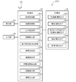
- FIG. 4 is a diagram illustrating an example of route evaluation information output by an information output unit in FIG. 3. 4 is a flowchart illustrating an example of a process executed by the management server in FIG. 3;
- FIG. 2 is a block diagram illustrating a schematic configuration of an administrator terminal in FIG. 1.
- the route subdividing device can be used in a management system of various types of business that manages a worker who moves in a plurality of work areas to perform a work and a movement route during the work.
- a delivery member applies to a management system for posting and delivery services for posting and delivering postal matter such as luggage, flyers, letters, and postcards. That is, an example will be described in which a delivery person who performs posting and delivery work at a delivery site such as a delivery company or a post office and a traveling route at the time of delivery are managed.
- work areas are set so that the required time in each work area is equal in order to allocate posting and delivery work to each delivery member in a well-balanced manner.
- the required time may be longer or shorter than expected due to an increase or decrease in the number of delivery destinations in the work area or a change in surrounding traffic conditions.
- the route subdivision device is configured as described below so that the moving route during the work of posting and delivery can be evaluated in terms of the required time for each work area.
- FIG. 1 is a diagram illustrating an example of a system configuration of the management system 100.
- the management system 100 includes a plurality (two in FIG. 1) of deliveryman terminals 1A and 1B connected by a network 4 including a public wireless communication network represented by the Internet network and a mobile phone network. , A management server 2 and an administrator terminal 3.
- the management server 2 and the administrator terminal 3 as a whole constitute the route subdivision device 5 according to the embodiment of the present invention.
- the management server 2 or the administrator terminal 3 may constitute the route subdivision device 5 alone.
- the network 4 includes a closed communication network provided for each predetermined management area, for example, a wireless LAN, Wi-Fi (Wireless Fidelity) (registered trademark), or the like.
- the courier terminals 1A and 1B are cradles of vehicles 6A and 6B that the courier 6A and 6B store in the pockets of their clothes, carry bags and pouches, or use them for the work of posting and delivery. It can be installed and used in such places.
- a smartphone, a tablet terminal, a mobile phone, a PDA (Personal Digital Assistant), and various wearable terminals that can be connected to public wireless communication are collectively referred to as deliveryman terminals 1A and 1B.
- Deliveryman terminals 1A and 1B have a common configuration. Note that the number of the delivery terminal 1A, 1B may be three or more.
- the vehicles 6A and 6B are transport vehicles such as four-wheeled vehicles, motorcycles, bicycles, wheelbarrows, and the like. In FIG. 1, as an example, they are widely used for posting and delivery of postal items such as luggage, flyers, letters, and postcards.
- a light truck (for example, a truck with a predetermined displacement or less) 6A and a motorized bicycle (for example, a motorcycle with a motor with a displacement of not more than a predetermined displacement) 6B are shown.
- the delivery members A and B may perform posting and delivery work on foot without using the vehicles 6A and 6B.
- ⁇ Delivery terminal 1A, 1B> First, the delivery terminal 1A, 1B will be described. Various application software can be installed on the delivery terminal 1A, 1B, and the delivery terminal 1A, 1B according to the present embodiment configures a management system by the application software installed on the smartphone. By using a commercially available smartphone, the cost for building the system can be reduced.
- FIG. 2 is a block diagram showing a schematic configuration of the delivery terminal 1A, 1B.
- the delivery terminal 1A includes a control unit 10, a storage unit 11, a wireless unit 12, a sensor unit 13, a display unit 14, and an input unit 15.
- the storage unit 11 is configured by a semiconductor memory, a hard disk, or the like.
- the storage unit 11 stores various information such as an operating system (OS), software including an application program for supporting posting and delivery work, map information such as a road map and a house map, and customer information of a delivery destination. It is memorized.
- the customer information includes information associated with the customer, such as the presence or absence of a delivery box, in addition to the delivery address and telephone number.
- the software, the map information, and the customer information may be stored in the storage unit 11 in advance, or may be acquired from the management server 2.
- the wireless unit 12 includes a DSP (Digital Signal Processor) and the like, and is configured to be able to wirelessly communicate with the management server 2 via a wireless communication network represented by a mobile phone network such as 3G, LTE, 4G, or 5G.
- the wireless unit 12 may be configured to include a proximity wireless communication unit (not shown) to which a proximity wireless communication technology such as Wi-Fi (registered trademark) and Bluetooth (registered trademark) can be applied.
- the wireless unit 12 transmits to the management server 2 a login ID (also referred to as “deliverer ID”) for identifying the deliverers A and B, current position information and speed information of the deliverers A and B or the vehicles 6A and 6B. be able to.
- a login ID also referred to as “deliverer ID”
- the sensor unit 13 receives positioning signals from a plurality of GPS satellites, measures the absolute positions (latitude, longitude) of the deliverers A and B corresponding to the deliverer terminals 1A and 1B, and calculates the angular velocity. It is composed of a gyro sensor 13b to detect. If it is not possible to receive a positioning signal from a GPS satellite, APS (Assisted Global Positioning System) communication is used, and the deliverers A, B or the vehicle are based on the base station information of the wireless communication network acquired from the wireless unit 12. The current positions of 6A and 6B can also be calculated.
- APS Assisted Global Positioning System
- the display unit 14 is configured by a display device such as a liquid crystal display or an organic EL panel.
- the display unit 14 receives an instruction from the control unit 10 and displays a map, icons of operation buttons for a touch panel, and the like, and also displays the current position of the delivery personnel A and B or the vehicles 6A and 6B, around the current position, and the delivery destination. Various information such as a map of the vicinity can be displayed.
- the input unit 15 includes physical switches such as numeric keys operated by the delivery personnel A and B, and input devices (not shown) such as a touch panel provided on the display surface of the display unit 14.
- a signal based on an operation input from the input unit 15, for example, pressing of the ten keys by the delivery personnel A and B and pressing of the touch panel is output to the control unit 10, thereby performing an operation such as switching of the screen display on the display unit 14.
- a and B can do it.
- the deliveryman terminals 1A and 1B can further include a speaker, a vibrator, a light, a microphone, and the like.
- the speaker, vibrator, and light notify the delivery person of various kinds of information by sound, vibration, and light.
- the speaker outputs sound to the delivery person, and the microphone collects sound or the like emitted by the delivery person.
- various information can be output from the speaker as voice, and various commands from the delivery person who have been voice-inputted through the microphone can be input to the control unit 10 using voice recognition technology.
- the control unit 10 includes a microprocessor having a CPU, a RAM, a ROM, an I / O, and the like.
- the CPU executes a program stored in advance and exchanges signals with the storage unit 11, the wireless unit 12, the sensor unit 13, the display unit 14, and the input unit 15.
- the control unit 10 has a display control unit 101, a connection processing unit 102, and a position information notification unit 103 as a functional configuration.
- the display control unit 101 generates an image signal and transmits it to the display unit 14 in response to an operation of the input unit 15 or reception of various types of information by the wireless unit 12, so that the screen display by the display unit 14 is performed. Control.
- the screen display that the display control unit 101 displays on the display unit 14 includes a login screen for logging in to the management system 100 and the like.
- the connection processing unit 102 transmits the login ID and the password input by the deliverers A and B via the input unit 15 to the management server 2 via the wireless unit 12 on the login screen displayed on the display unit 14. Thereby, the deliveryman terminals 1A and 1B are connected to the management server 2 in a communicable state.
- the log-in input by the deliveryman is executed when the deliveryman starts, that is, when the deliveryman departs from the delivery base.
- the connection processing unit 102 transmits the logout to the management server 2 via the wireless unit 12.
- the logout input by the deliveryman is executed when the deliveryman finishes working, that is, when the deliveryman returns to the delivery base. Note that logout may be automatically executed based on time or position information when the delivery member returns to the delivery base.
- the position information notification unit 103 is configured to provide current position information of the deliverers A and B or the vehicles 6A and 6B that move together with the deliverer terminals 1A and 1B calculated based on the GPS signals received by the sensor unit 13 (GPS sensor 13a). And the current time information and the like obtained from a clock unit (not shown) are transmitted to the management server 2 via the wireless unit 12 at predetermined time intervals (for example, every one second) in association with the deliveryman ID.
- the time information includes not only the time but also information such as the date.
- the positions of the deliverers A and B or the vehicles 6A and 6B change every moment, when the current position information is acquired at predetermined time intervals, the position obtained from the latest current position information and the actual position are strictly determined. In other words, they may not match. However, since the deviation is small, a position obtained from the current position information acquired at predetermined time intervals can be regarded as the current position.
- a plurality of pieces of the current position information, current time information, and the like of the deliverers A and B or the vehicles 6A and 6B acquired at predetermined time intervals may be transmitted together (so-called burst transmission).
- the acquisition time interval (for example, one second interval) of the current position information of the delivery person or the vehicle, the number of transmissions at one time when a plurality of burst transmissions are collectively performed, and the like can be set in advance.
- management server 2 ⁇ Management server 2> Next, the management server 2 will be described. Although the management server 2 is described as one server having various functions in the present embodiment, the management server 2 may be a distributed server configured with different servers for each function, or may be implemented as a cloud server (virtual server). May be done.
- a cloud server virtual server
- FIG. 3 is a block diagram showing a schematic configuration of the management server 2.
- the management server 2 includes a control unit 20, a storage unit 21, a communication unit 22, a display unit 24, and an input unit 25.
- the display unit 24 and the input unit 25 can be omitted. Further, the display unit 24 and the input unit 25 can be configured by another information terminal (not shown) connected to the management server 2.
- the storage unit 21 is configured by a semiconductor memory, a hard disk drive, or the like.
- the storage unit 21 stores software called an operating system (OS) or an application, and various other information. Therefore, various storage areas such as a deliveryman information area 211, a vehicle information area 212, a posting destination or delivery destination information area 213, a map information area 214, and a management information area 215 are secured in the storage unit 21.
- the information area is, for example, a table in a database management system.
- the delivery member information area 211 for each employee ID (also referred to as “delivery member ID”), which is identification information of a delivery member, basic information on the delivery person, for example, the name of the delivery member, the affiliation base ID And the like are stored.
- a vehicle ID which is identification information of the vehicles 6A and 6B, is stored in association with the vehicle used by the deliveryman, that is, the deliveryman ID.
- the association of the vehicle ID with the delivery person ID is set in advance by, for example, an administrator of the delivery site before starting the posting and delivery work for one day.
- the vehicle information area 212 stores, for each vehicle ID, information related to the vehicle, for example, information such as the type of vehicle such as a four-wheeled vehicle, a motorcycle, and a bicycle, and the size of a luggage compartment.
- the posting destination or delivery destination information area 213 includes a delivery destination address (latitude and longitude) and a telephone number, a work area including the delivery destination, deliverymen A and B in charge of the work area including the delivery destination, and the like. Delivery destination information is stored.
- the work area is an area set in advance by a manager of a delivery base for the purpose of allocating posting and delivery work to each delivery person. For example, a delivery destination of 10 to 30 households corresponding to one or a plurality of districts is used. It consists of.
- the delivery members A and B are in charge of posting and delivery work in an assigned area including a plurality of work areas.
- the map information area 214 stores map information such as a road map and a house map in advance.
- the map information includes road link information, display map data for displaying roads, backgrounds of road maps, and the like. These map information are updated regularly.
- management information area 215 information on scheduled routes set in advance by the manager of the delivery base, time-series position information of the deliverers A and B or the vehicles 6A and 6B obtained from the deliverer terminals 1A and 1B, and work information Position information of a boundary point between the areas is stored.
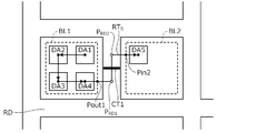
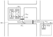
- FIGS. 4A and 4B are diagrams illustrating an example of the planned route stored in the management information area 215.
- the manager of the delivery base determines in advance all (five in the figure) delivery destinations DA1 to DA5 which are controlled by the delivery base in a plurality (for example, a block, an address, or a large-scale apartment house) as one unit (FIG. Then, two work areas BL1 and BL2 are sorted. In addition, delivery members A and B responsible for posting and delivery work in the respective work areas are assigned to the respective work areas BL1 and BL2.
- the delivery order of the work area (BL1 ⁇ BL2 in the example in the figure) and the delivery order of the delivery destination including the first delivery destination (DA1, DA5) and the last delivery destination (DA4) in each work area (FIG. In the example, (DA1 ⁇ DA2...) Is set.
- the information on the planned route in which the work area numbers BL1 and BL2, the deliverers A and B, and the delivery order are associated with the addresses (latitude and longitude) of the delivery destinations DA1 to DA5 via the manager terminal 3.
- Set as Information on the scheduled route set via the administrator terminal 3 is transmitted to the management server 2 and stored in the management information area 215.
- the communication unit 22 When the communication unit 22 performs transmission and reception with the deliveryman terminals 1A and 1B, the communication unit 22 implements a communication protocol capable of performing wireless communication such as 3G, LTE, 4G, and 5G. On the other hand, when performing transmission and reception with the administrator terminal 3, the communication unit 22 implements a communication protocol capable of performing wired communication (for example, an Internet line or the like) or wireless communication.
- a communication protocol capable of performing wireless communication such as 3G, LTE, 4G, and 5G.
- the communication unit 22 when performing transmission and reception with the administrator terminal 3, the communication unit 22 implements a communication protocol capable of performing wired communication (for example, an Internet line or the like) or wireless communication.
- the control unit 20 includes a processor having a CPU, a RAM, a ROM, an I / O, and the like.
- the control unit 20 includes, as functional components, a connection processing unit 201, an information acquisition unit 202, an area setting unit 203, a route setting unit 204, an entry / exit point setting unit 205, a boundary setting unit 206, a route calculation It has a unit 207, a required time calculation unit 208, a route calculation unit 209, and an information output unit 210.
- the connection processing unit 201 executes a login process from the delivery terminal 1A, 1B, and performs a connection process with the delivery terminal 1A, 1B. Further, the connection processing unit 201 executes a logout process from the delivery terminal 1A, 1B, and terminates the connection with the delivery terminal 1A, 1B. Further, the connection processing unit 201 executes a login process from the administrator terminal 3 to perform a connection process with the administrator terminal 3, and executes a logout process from the administrator terminal 3 to perform a connection process with the administrator terminal 3. Terminate the connection.
- the information acquisition unit 202 receives data transmitted from the delivery terminal 1A, 1B to the management server 2 and data transmitted from the administrator terminal 3 to the management server 2 via the communication unit 22. Get various information.
- the information acquired by the information acquisition unit 202 includes the position information of the vehicles 6A and 6B transmitted from the position information notification unit 103 of each of the deliveryman terminals 1A and 1B, the time information corresponding thereto, and the information transmitted from the administrator terminal 3.
- the position information is specifically represented by latitude and longitude.
- the area setting unit 203 sets the work areas BL1 and BL2 as areas on the map based on the map information stored in the map information area 214 and the information on the planned route stored in the management information area 215.
- the work area BL1 including the delivery destinations DA1 to DA4 is an area including the delivery destinations DA1 to DA4, for example, a predetermined distance (for example, from the delivery destinations DA1 to DA4) to the road RD side. 5m), which is set as an area inside the separated boundary line.
- the position information of the area indicating the work areas BL1 and BL2 set by the area setting unit 203 is also stored in the management information area 215 as the information of the planned route.
- the route setting unit 204 sets the planned route RTS as a polyline along the road RD on the map based on the map information stored in the map information area 214 and the information on the planned route stored in the management information area 215. As shown in FIGS. 4A and 4B, the scheduled route RTS is set as a polyline passing through the delivery destinations DA1 to DA5 in the delivery order. In each work area, for example, in the work area BL1, the scheduled route RTS passes from the first delivery destination DA1 to the last delivery destination DA4 in the work area BL1 in the delivery order.
- the scheduled route RTS proceeds to a point on the road RD that passes to advance to the next work area BL2, for example, a point PRD1 on the road RD closest to the delivery destination DA4. . Further, the scheduled route RTS proceeds to a point PRD2 on the road RD closest to the first delivery destination DA5 in the next work area BL2, and proceeds to the first delivery destination DA5 in the work area BL2. Therefore, in the example of FIG. 4A, a polyline having vertices DA1, DA2, DA3, DA4, PRD1, PRD2, and DA5 is set as the scheduled route RTS.
- the planned route RTS is set to pass, for example, a point PRD3 at the center of the intersection. Therefore, in the example of FIG. 4B, a polyline having DA1, DA2, DA3, DA4, PRD1, PRD3, PRD2, and DA5 as vertices is set as the scheduled route RTS.
- the position information of the polyline indicating the planned route RTS set by the route setting unit 204 is also stored in the management information area 215 as information of the planned route.
- the entry / exit point setting unit 205 sets an entry point and an exit point of the planned route RTS in the work areas BL1 and BL2 on the map based on the information on the planned route stored in the management information area 215. For example, as shown in FIGS. 4A and 4B, an exit point Pout1 of the planned route RTS in the work area BL1 and an entry point Pin2 of the planned route RTS in the work area BL2 are set.
- the escape point Pout1 of the planned route RTS in the work area BL1 is set as an intersection of the planned route RTS and a boundary line defining the work area BL1.
- the entry point Pin2 of the planned route RTS in the work area BL2 is set as an intersection of the planned route RTS and a boundary line defining the work area BL2.
- the position information of the entry point Pin2 and the exit point Pout1 set by the entry / exit point setting unit 205 is also stored in the management information area 215 as information of the planned route.
- the boundary setting unit 206 sets a boundary point (boundary line) between the work area BL1 and the work area BL2 on the map that are continuous in the delivery order based on the information on the planned route stored in the management information area 215. For example, as shown in FIG. 4A, the length of the polyline (in the figure, Pout1-PRD1-PRD2-Pin2) from the exit point Pout1 of the immediately preceding work area BL1 to the entry point Pin2 of the immediately succeeding work area BL2 is a predetermined distance L1.
- the boundary line CT may be set at the midpoint of the entire polyline from the exit point Pout1 of the immediately preceding work area BL1 to the approach point Pin2 of the immediately succeeding work area BL2.
- the length of the polyline (in the figure, Pout1-PRD1-PRD3-PRD2-Pin2) from the exit point Pout1 of the immediately preceding work area BL1 to the approach point Pin2 of the immediately succeeding work area BL2 is predetermined. If the distance is equal to or longer than the distance L1, a boundary line CT that is orthogonal to the midpoint of the first line segment (in the example of the drawing, the line segments PRD1 to PRD3) after exiting from the immediately preceding work area BL1 is set. Further, a boundary line CT orthogonal to the midpoint of the last line segment (the line segment PRD3-PRD2 in the example in the figure) before entering the immediately subsequent work area BL2 is set.
- the predetermined length L2 of the boundary line CT may be changed according to the width of the road RD.
- the line segments constituting the polyline are not limited to straight line segments, but may be curved line segments.
- the boundary line CT is set so as to be orthogonal to the tangent of the curved line having the midpoint of the curved line as a contact point.
- Position information of the plurality of boundary lines CT set by the boundary setting unit 206 is stored in the management information area 215 as position information of a boundary point between the work areas BL1 and BL2.
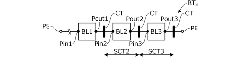
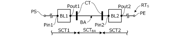
- FIGS. 5A to 5F are diagrams illustrating the setting of a section corresponding to a work area by the boundary setting unit 206.
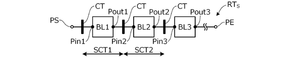
- FIG. In the example of FIGS. 5A to 5F, a scheduled route RTS from a start point PS such as a delivery base to an end point PE, which passes through three consecutive work areas BL1 to BL3 in the delivery order, is shown.
- the planned route RTS is divided into work sections SCT1 to SCT3 corresponding to the work areas BL1 to BL3 by a plurality of boundary lines CT set before and after the work areas BL1 to BL3. For example, as shown in the example of FIG.
- a work section SCT2 on the planned route RTS corresponding to the work area BL2 is defined by a boundary line CT set before and after the work area BL2.
- the boundary line CT before the work area BL2 is set on the planned route RTS from the exit point Pout1 of the immediately preceding work area BL1 to the approach point Pin2 of the work area BL2.
- the boundary line CT after the work area BL2 is set on the planned route RTS from the exit point Pout2 of the work area BL2 to the approach point Pin3 of the work area BL3 immediately after.
- the work section SCT1 corresponding to the work area BL1 immediately after the start point PS of the planned route RTS is also defined by the boundary line CT set before and after the work area BL1.
- the boundary line CT before the work area BL1 is set on the planned route RTS from the starting point PS to the entry point Pin1 of the work area BL1.
- a work section SCT3 corresponding to the work area BL3 immediately before the end point PE of the planned route RTS is also defined by the boundary line CT set before and after the work area BL3.
- the boundary line CT after the work area BL3 is set on the planned route RTS from the escape point Pout3 of the work area BL3 to the end point PE.
- two boundary lines CT are set between the work areas.
- the work area BL1 is determined.
- Two boundary lines CT are set on the planned route RTS with the work area BL2.
- the planned route RTS from the boundary line CT immediately before the work area BL1 to the boundary line CT immediately before the work area BL1 is defined as the work section SCT1 corresponding to the work area BL1. It is defined as a work section SCT2 corresponding to BL2.
- the planned route RTS from the boundary line CT immediately after the work area BL1 to the boundary line CT immediately before the work area BL2 is a moving section SCTBA between the work areas corresponding to an area (non-work area) BA which is not a work area. Is defined as
- the example of FIG. 5E is a case where the length of the journey (polyline) from the starting point PS of the scheduled route RTS to the entry point Pin1 of the work area BL1 immediately after is longer than the predetermined distance L1.
- a boundary line CT orthogonal to the midpoint of the last line segment before entering the work area BL1 among the line segments constituting the polyline is set.
- the scheduled route RTS from the starting point PS to the boundary line CT immediately before the work area BL1 is defined as a moving section SCTBA from the delivery base to the work area corresponding to the non-work area BA.
- the planned route RTS from the boundary line CT immediately after the work area BL3 to the end point PE is defined as a moving section SCTBA from the work area to the delivery base corresponding to the non-work area BA.
- the travel route calculation unit 207 calculates the travel route (polyline) on the planned route RTS for each of the working sections SCT1 to SCT3 or the moving section SCTBA. Calculate the length.
- the length of the route on the planned route RTS for each of the working sections SCT1 to SCT3 or the moving section SCTBA calculated by the route calculating section 207 is stored in the management information area 215 as information of the planned route.
- the required time calculating unit 208 calculates the required time for each of the working sections SCT1 to SCT3 or the moving section SCTBA based on the length of the route on the scheduled route RTS calculated by the route calculating unit 207 and the preset planned traveling speed. Is calculated.
- the planned moving speed is set to, for example, about 10 km / h according to the work content in the work area and traffic conditions around the work area.
- the planned moving speed may be set for each work area in consideration of the scale of the apartment house included in the delivery destination in the work area, traffic conditions around the house, and the like. In addition, it may be set for each delivery member in consideration of the transportation method used by the delivery member, the proficiency of posting and delivery work, and the like.
- the required time for each of the working sections SCT1 to SCT3 or the moving section SCTBA calculated by the required time calculating section 208 is also stored in the management information area 215 as information on the planned route.
- the route calculation unit 209 calculates the actual route that the deliverers A and B have actually moved based on the time-series position information of the deliverers A and B or the vehicles 6A and 6B stored in the management information area 215.
- FIG. 6 is a diagram for explaining an example of the actual route RTA calculated by the route calculating unit 209, and shows the positions of the deliverers A and B, for example, the deliverers A at predetermined time intervals by plotting.
- the actual route RTA of the delivery person A is calculated as a result of connecting plots corresponding to the position of the delivery person A in time series.
- the actual route RTA is calculated as a polyline that connects adjacent plots along a time series with straight lines.
- the required time calculation unit 208 calculates the actual route RTA based on the time-series position information of the deliverers A and B or the vehicles 6A and 6B stored in the management information area 215 and the position information of the boundary point between the work areas.
- the required time is calculated for each of the upper working sections SCT1 to SCT3 or the moving section SCTBA.
- plots PAin1 and PAin2 immediately after a plurality of (two in the figure) boundary lines CT are converted to the actual route RTA. They are selected as the starting points of the next work sections SCTA1 and SCTA2 on the RTA, respectively.
- the plots PAout0 and PAout1 immediately before the plurality of boundary lines CT are respectively selected as the end points of the previous moving section SCTBA or the work section SCTA1 on the actual route RTA.
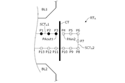
- FIG. 7 is a diagram for explaining the selection of the start point and the end point of each section on the actual route RTA by the required time calculation unit 208.
- the plots P1 to P13 show the time-series positions of the deliverers A and B.
- the boundary line CT in FIG. 7 specifies the end point of the work section SCT1 and the start point of the work section SCT2.
- the actual route RTA may pass through the boundary line CT a plurality of times. That is, the actual route RTA including the plots P1 to P13 first passes through the boundary line CT between the plots P3 and P4, and then passes through the boundary line CT again between the plots P10 and P11. .
- the actual route RTA is divided into a work section SCT1 and a work section SCT2 between a plot P3 and a plot P4 that pass through the boundary line CT first in a time series. That is, plot P3 is selected as plot PAout1 immediately before the boundary line CT (end point of the work section SCT1), and plot P4 is selected immediately after the boundary line CT as plot PAin2 (start point of the next work section SCT2 after the work section SCT1). . Therefore, even when the actual route RTA reciprocates in the same place, the actual route RTA can be divided into a plurality of sections in the order of passage in time series.
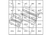
- a method of dividing the actual route RTA using the mesh-shaped areas AR1 to AR25 corresponding to the latitude and longitude as shown in FIG. 8 can be considered.
- the actual route RTA passes through the actual route RTA in time series. It is difficult to divide into a plurality of sections according to the order.
- each section on the actual route RTA is determined. That is, the starting point of the actual route RTA from the plot PAin0 to the plot PAout0 is determined as the moving section SCTBA from the delivery base corresponding to the non-work area BA on the actual route RTA to the working area BL1. Further, a section from the plot PAin1 to the plot PAout1 is determined as a work section SCTA1 corresponding to the work area BL1 on the actual route RTA. The actual route RTA ahead of the plot PAin2 is defined as a work section SCTA2 corresponding to the work section SCTA2 corresponding to the work area BL2.
- the required time for each section is calculated. That is, the time required to pass through the moving section SCTBA is calculated based on the time information of the plots PAin0 and PAout0, and the time required to pass through the work section SCTA1 is calculated based on the time information of the plots PAin1 and PAout1. Is done.
- the required time for each of the working sections SCT1 to SCT3 or the moving section SCTBA for the actual route RTA calculated by the required time calculating section 208 is transmitted to the manager terminal 3 of the delivery base as route evaluation information.
- the manager of the delivery base can evaluate the travel route at the time of delivery by checking the required time for each section via the manager terminal 3.
- the information output unit 210 outputs various information by transmitting data from the management server 2 to the administrator terminal 3 via the communication unit 22.
- the information output by the information output unit 210 includes the required time for each section transmitted to the administrator terminal 3 and the like.
- FIG. 9 is a diagram illustrating an example of the route evaluation information output by the information output unit 210.
- the route evaluation information includes the required time (actual required time) for each section on the actual route RTA, and the required time (planned) for each section on the scheduled route RTS stored in the management information area 215. ), And the difference between the actual required time and the scheduled required time.
- the manager of the delivery site confirms the information via the manager terminal 3 to reduce, for example, a work area where the actual required time is longer than the scheduled required time or a task where the actual required time is shorter. The area can be expanded. By adjusting the required time in each work area to be equal, it is possible to allocate posting and delivery work to each of the delivery personnel A and B in a well-balanced manner.
- FIG. 10 is a flowchart showing an example of processing executed by the CPU of the management server 2 according to a program stored in advance. The process shown in this flowchart is started, for example, when an output request for route evaluation information is received from the administrator terminal 3.
- step S1 the output request of the route evaluation information received from the administrator terminal 3 via the communication unit 22 is read by the processing of the information acquisition unit 202, and the designated deliveryman A in the designated delivery period is read.
- step B the information on the scheduled route and the information on the actual route (time-series position information) are read. Further, the map information stored in the map information area 214 is read.
- step S2 a plurality of work areas BL1 to BL3 are set on the map by the processing of the area setting unit 203 based on the information on the planned route and the map information.
- step S3 the route setting unit 204 sets a planned route RTS that passes through the work areas BL1 to BL3 set in step S2 in the delivery order based on the planned route information and the map information.
- step S4 the processing of the entry / exit point setting unit 205 causes the planned route RTS set in step S3 in the work areas BL1 to BL3 set in step S2 based on the planned route information and the map information.
- the entry points Pin1 to Pin3 and the exit points Pout1 to Pout3 are set.
- step S5 by the processing in the boundary setting unit 206, between the work areas BL1 to BL3 or between the work areas BL1 to BL3 and the non-work area BA set in step S2 based on the information of the planned route. Are set with a plurality of boundary lines CL.
- step S6 the processing sections SCT1 to SCT3 divided by the plurality of boundary lines CL set in step S5, based on the information on the planned route and the position information on the boundary point, by the processing in the route calculating unit 207.
- the length of the route on the planned route RTS is calculated for each movement section SCTBA.
- step S7 the required time for each section is calculated by the required time calculation unit 208 based on the length of the route on the planned route RTS calculated in step S3 and the predetermined planned traveling speed. Is calculated.
- step S8 the route calculation unit 209 specifies the route based on the actual route information (time-sequential position information) for the deliverers A and B specified in the route evaluation information output request.
- the actual route RTA that the delivery members A and B actually moved is calculated.
- step S9 the actual time on the actual route RTA is calculated by the required time calculating unit 208 based on the position information of the boundary point set in step S5 and the information on the actual route RTA calculated in step S8.
- the actual required time for each of the working sections SCTA1 to SCTA3 or the moving section SCTBA is calculated.
- step S10 the information output unit 210 processes the route evaluation information including the scheduled required time for each section, the actual required time, and the difference between the actual required time and the scheduled required time into the administrator terminal. Send to 3.
- the manager of the delivery base checks the route evaluation information including the scheduled required time and the actual required time for each section via the manager terminal 3, thereby evaluating the moving route of the posting and delivery work. Can be. That is, since the travel route is evaluated as the required time for each section, for example, it is possible to periodically review the workload for each work area corresponding to the work section. Work can be allocated in a well-balanced manner.
- the manager terminal 3 is used by the manager of the delivery base to set and evaluate the moving routes of the delivery personnel A and B who perform posting and delivery work.
- the administrator terminal 3 includes various computers such as a personal computer, a tablet terminal, and a smartphone provided at the delivery site, and transmits and receives information to and from the management server 2 via the network 4.
- FIG. 11 is a block diagram showing a schematic configuration of the administrator terminal 3. As shown in FIG. As shown in FIG. 11, the administrator terminal 3 includes a control unit 30, a storage unit 31, a communication unit 32, a display unit 34, and an input unit 35.
- the storage unit 31 is configured by a semiconductor memory, a hard disk drive, or the like.
- the storage unit 31 stores software called an operating system (OS) or an application, and various other information.
- OS operating system
- the communication unit 32 implements a communication protocol capable of performing wired communication (for example, an Internet line or the like) or wireless communication such as 3G, LTE, 4G, or 5G, and connects to the management server 2 to transmit and receive various data.
- a communication protocol capable of performing wired communication (for example, an Internet line or the like) or wireless communication such as 3G, LTE, 4G, or 5G, and connects to the management server 2 to transmit and receive various data.
- the display unit 34 is configured by a display device such as a liquid crystal display or an organic EL panel, and displays a map, an icon of an operation button for a touch panel, and the like in response to an instruction from the control unit 30.
- the display unit 34 displays the route evaluation information and the like transmitted from the information output unit 210 of the management server 2.
- the input unit 35 includes a physical switch such as a numeric keypad operated by an administrator, and an input device (not shown) such as a touch panel provided on the display surface of the display unit 34.
- a command to switch the display screen of the display unit 34 is input via the input unit 35.
- Setting of work areas BL1 and BL2 sorting of delivery destinations DA1 to DA5), assignment of delivery personnel A and B to each work area, delivery order of work areas BL1 and BL2, and delivery of delivery destinations DA1 to DA5 in each work area The setting of the order can be performed via the input unit 35.
- the control unit 30 includes a processor having a CPU, a RAM, a ROM, an I / O, and the like.
- the control unit 30 includes a display control unit 301, a connection processing unit 302, an evaluation information requesting unit 303, and a server information obtaining unit 304 as a functional configuration.
- the display control unit 301 controls the screen display by the display unit 34 by generating an image signal according to the operation of the input unit 35 and transmitting the image signal to the display unit 34.
- the screen displayed by the display control unit 301 on the display unit 34 includes a login screen for logging in to the management system 100, work areas BL1 and BL2, deliverymen A and B in charge of each work area, and work areas BL1 and BL2.
- a setting screen for setting the delivery order and the delivery order of the delivery destinations DA1 to DA5 in each work area, a route evaluation screen for displaying route evaluation information (FIG. 9), and the like are included.
- the connection processing unit 302 executes a log-in process to the management server 2 using, for example, an identification number (base manager ID) for identifying a manager or a responsible person of the delivery base and a password.
- an identification number for identifying a manager or a responsible person of the delivery base and a password.
- the evaluation information requesting unit 303 transmits a request for output of route evaluation information to the management server 2 by designating a delivery person and a delivery period in accordance with an operation of the input unit 35 by the administrator.
- the server information acquisition unit 304 acquires the route evaluation information and the like transmitted from the management server 2 (the information output unit 210).
- the display unit 34 displays the route evaluation information (FIG. 9).
- the delivery person A driving the vehicle 6A departs from the delivery base, that is, at the start of business, on the login screen displayed on the display unit 14 of the delivery person terminal 1A
- the delivery person A inputs his / her login ID via the input unit 15 and Enter your password.
- the management server 2 performs a connection process with the delivery terminal 1A.
- the delivery terminal 1A communicates with the management server 2 at predetermined time intervals (for example, at one-second intervals), and transmits the position information of the delivery person A or the vehicle 6A to the management server 2. Communication between the delivery terminal 1A and the management server 2 is continued until the delivery terminal 1A performs a logout operation.
- the manager of the delivery site inputs the site manager ID and the password via the input unit 35 on the login screen displayed on the display unit 34 of the manager terminal 3.
- the management server 2 performs a connection process with the administrator terminal 3.
- the administrator specifies the delivery person A and the delivery period via the input unit 35 (touch panel) and inputs an output request for route evaluation information
- the output request for route evaluation information is transmitted to the management server 2.
- the management server 2 sets a plurality of work areas BL1 to BL3 in which the delivery person A was in charge of the posting and delivery work during the delivery period specified in the route evaluation information, and sets the work areas BL1 to BL3.
- Are set steps S1 to S3).
- entry points Pin1 to Pin3 and exit points Pout1 to Pout3 of the planned route RTS in the work areas BL1 to BL3 are set, and a plurality of entry points are set between the work areas BL1 to BL3 or between the work areas BL1 to BL3 and the non-work area BA. Is set (steps S4 and S5).
- the length of the route on the scheduled route RTS is calculated, and the scheduled required time for each section is calculated (step S6). S7).
- the management server 2 calculates the actual route RTA that the delivery person A actually moved during the delivery period specified in the route evaluation information, and based on the position information of the boundary point, the actual work section SCTA1 on the actual route RTA.
- the actual required time is calculated for each of ⁇ SCTA3 or moving section SCTBA (steps S8, S9).
- the information on the scheduled required time and the actual required time for each section calculated by the management server 2 is transmitted to the administrator terminal 3 as route evaluation information and displayed on the display unit 34 (step S10).
- the manager of the delivery base checks the route evaluation information including the scheduled required time and the actual required time for each section via the manager terminal 3, thereby evaluating the moving route of the posting and delivery work. Can be. This makes it possible to review the work load of each work area corresponding to the work section as necessary, and to allocate the posting and delivery work to each delivery member in a well-balanced manner. For example, if the actual required time is considered to be longer or shorter than the planned required time due to an increase or decrease in the number of deliveries included in each work area or a change in surrounding traffic conditions, etc. You can review the range of the area.
- the route subdividing device 5 subdivides a moving route when performing an operation.
- the route subdividing device 5 includes an area setting unit 203 for setting a plurality of work areas on a map, and a scheduled route from a start point PS to an end point PE so as to pass through continuous work areas BL1 to BL3 among the plurality of work areas.
- Between the boundary lines to set the boundary line CT Includes a section 206, and a journey calculator 207 for calculating the length of the journey on the scheduled route RTS every work section SCT2 divided by a plurality of boundary lines CT set by boundary setting unit 206 (FIG. 3).
- delivery order information including the first delivery destination (DA1, DA5) and the last delivery destination (DA4) in each work area BL1, BL2, which are set in advance in association with delivery destination addresses (latitude, longitude).
- the planned route RTS can be automatically subdivided based on (planned route information) (FIGS. 4A to 5F).
- the route subdivision device 5 calculates the required time required to pass through the length of the journey based on the length of the journey calculated by the journey calculating unit 207 and the predetermined planned moving speed. 208 (FIG. 3). Thus, it is possible to evaluate a moving route when performing a work by moving a plurality of work areas in terms of a required time for each fine section corresponding to each work area.
- the route setting unit 204 sets the scheduled route RTS so as to pass through the work area BL1 after the start point PS (FIGS. 5B and 5E).
- the boundary setting unit 206 sets a boundary line CT between the start point PS and the entry point Pin1 in the work area BL1 (FIGS. 5B and 5E). Thereby, the section corresponding to the first work area on the movement route can be appropriately set.
- the route setting unit 204 sets the scheduled route RTS so as to pass through the end point PE next to the work area BL3 (FIGS. 5C and 5F).
- the boundary setting unit 206 sets a boundary line CT between the escape point Pout3 and the end point PE in the work area BL3 (FIGS. 5C and 5F). This makes it possible to appropriately set the section corresponding to the last work area on the moving route.
- the area setting unit 203 sets a non-work area BA between the work area BL1 and the work area BL2 or between the work area BL2 and the work area BL3 (FIG. 5D).
- the boundary setting section 206 is provided between the work area BL1 or the work area BL2 immediately before the non-work area BA set by the area setting section 203 and the non-work area BA, and immediately after the non-work area BA and the non-work area BA.
- a boundary line CT is set between the work area BL2 and the work area BL3 (FIG. 5D). Accordingly, even when there is a non-work area, which is an area where work is not performed, between work areas on the movement route, a section corresponding to the work area where work is performed can be appropriately set.
- the area setting part 203 is between the exit point Pout1 in the work area BL1 and the entry point Pin2 in the work area BL2 set by the approach / escape point setting part 205, or the escape point Pout2 and the work area BL3 in the work area BL2.
- the length of the route on the planned route RTS between the entry point Pin3 and the predetermined distance L1 is equal to or longer than the predetermined distance L1
- the non-work is performed between the work area BL1 and the work area BL2 or between the work area BL2 and the work area BL3.
- the area BA is set (FIG. 5D).
- the boundary setting section 206 is provided between the work area BL1 or the work area BL2 immediately before the non-work area BA set by the area setting section 203 and the non-work area BA, and immediately after the non-work area BA and the non-work area BA.
- a boundary line CT is set between the work area BL2 and the work area BL3 (FIG. 5D).
- the movement section SCTBA between the work areas corresponding to the non-work area BA and the work area are automatically distinguished from the sections SCT1 to SCT3, and the movement route can be subdivided (FIG. 5D).
- the area setting unit 203 sets a non-work area BA between the starting point PS and the work area BL1 (FIG. 5E).
- the boundary setting unit 206 sets the boundary lines CT between the start point PS and the non-work area BA and between the non-work area BA and the entry point Pin1 in the work area BL1 (FIG. 5E).
- the area setting unit 203 sets a non-work area BA between the work area BL3 and the end point PE (FIG. 5F).
- the boundary setting unit 206 sets the boundary lines CT between the escape point Pout3 and the non-work area BA in the work area BL3 and between the non-work area BA and the end point PE (FIG. 5F).
- the route subdividing device 5 acquires information on the positions of the deliverers A and B performing the posting and delivery work by moving through the plurality of work areas BL1 to BL3 and information on the time corresponding to the position.
- Unit 202 and a route calculation unit 209 that calculates the actual route RTA that the deliverers A and B have actually moved based on the position information and the time information acquired by the information acquisition unit 202 (FIG. 3). ).
- the required time calculation unit 208 divides the actual route RTA calculated by the route calculation unit 209 based on the time information acquired by the information acquisition unit 202 by using the plurality of boundary lines CT set by the boundary setting unit 206.
- the actual required time required to pass through the work sections SCT1 to SCT3 or the moving section SCTBA is calculated. This makes it possible to compare and evaluate the estimated required time for each section corresponding to each work area and the actual required time for a movement route when performing work by moving through a plurality of work areas.
- the route subdividing device 5 subdivides the moving route when performing the work of posting and delivery.
- the route subdividing device may be any device that subdivides the moving route when performing the work.
- the movement route when performing a work such as a facility inspection performed by patroling the equipment may be subdivided.
- the area setting unit 203 sets the work areas BL1 to BL3 as areas inside the boundary line separated by a predetermined distance from each delivery destination on the road RD side. Any type may be used as long as it sets a work area. For example, a work area including facilities on a road may be set.
- the route setting unit 204 sets the planned route RTS as a polyline along the road RD on the map. However, if the route setting unit sets a planned route passing through a plurality of work areas, Anything is fine.
- the entry / exit point setting unit 205 sets the entry point and the exit point of the work area as the intersection of the planned route RTS and the boundary line that defines the work area, but sets the entry point and the exit point.
- the entry / exit point setting unit is not limited to this.
- the first work point in each work area may be set as an entry point, and the last work point may be set as an exit point.
- the boundary setting unit 206 sets the boundary line CL that intersects (orthogonally) the planned route RTS, but the boundary setting unit that sets the boundary point is not limited to this.
- the entry point and the exit point of each work area may be directly used as the boundary points.
- the boundary point is not limited to the boundary line, and may be set by a geofence or the like.
- the information acquisition unit 202 acquires the information on the position calculated on the deliveryman terminals 1A and 1B side.
- the configuration of the information acquisition unit for acquiring the information on the position of the worker is different from this. Not exclusively.
- the position may be calculated by the management server 2 based on the GPS signals and the like received by the deliveryman terminals 1A and 1B.
- the route calculation unit 209 calculates the actual route RTA as a polyline obtained by connecting position plots adjacent to each other in a time series with a straight line. Any one may be used as long as it is calculated.
- the actual route may be calculated based on the moving average of the position plot.
Landscapes
- Engineering & Computer Science (AREA)
- Business, Economics & Management (AREA)
- Radar, Positioning & Navigation (AREA)
- Remote Sensing (AREA)
- Physics & Mathematics (AREA)
- General Physics & Mathematics (AREA)
- Human Resources & Organizations (AREA)
- Economics (AREA)
- Strategic Management (AREA)
- Quality & Reliability (AREA)
- Development Economics (AREA)
- Entrepreneurship & Innovation (AREA)
- Marketing (AREA)
- Operations Research (AREA)
- Automation & Control Theory (AREA)
- Tourism & Hospitality (AREA)
- General Business, Economics & Management (AREA)
- Theoretical Computer Science (AREA)
- Game Theory and Decision Science (AREA)
- Traffic Control Systems (AREA)
- Management, Administration, Business Operations System, And Electronic Commerce (AREA)
- Navigation (AREA)
Abstract
作業を行うときの移動経路を細分する経路細分装置(5)は、地図上に複数の作業エリアを設定するエリア設定部(203)と、複数の作業エリアのうちの連続した第1~第3エリアを通過するように始点から終点までの予定経路を設定する経路設定部(204)と、各作業エリアにおける予定経路の進入地点と脱出地点とを設定する進入脱出地点設定部(205)と、第1エリアの脱出地点と第2エリアの進入地点との間、および第2エリアの脱出地点と第3エリアの進入地点との間、にそれぞれ境界地点を設定する境界設定部(206)と、境界地点により分割された区間ごとに予定経路上の道程の長さを算出する道程算出部(207)とを備える。
Description
本発明は、移動経路を細分する経路細分装置に関する。
この種の技術として、従来、ユーザ端末のGPS受信機で受信されるGPS信号に基づく位置情報と時刻情報とに基づいて、任意の時刻におけるユーザの位置を把握するようにした装置が知られている(例えば特許文献1参照)。この特許文献1記載の装置では、特定の期間における複数の位置情報と時刻情報とに基づいて、その期間の移動経路を推定する。
しかしながら、上記特許文献1記載の装置は、移動経路の特定の区間を指定して所要時間を算出するものではないため、細かな区間ごとの移動経路を評価するために移動経路を細分することが難しい。
本発明の一態様は、作業を行うときの移動経路を細分する経路細分装置であって、地図上に複数の作業エリアを設定するエリア設定部と、複数の作業エリアのうちの連続した第1エリア、第2エリアおよび第3エリアを通過するように始点から終点までの予定経路を設定する経路設定部と、複数の作業エリアの各作業エリアにおける経路設定部により設定された予定経路の進入地点と脱出地点とを設定する進入脱出地点設定部と、進入脱出地点設定部により設定された第1エリアにおける脱出地点と第2エリアにおける進入地点との間、および第2エリアにおける脱出地点と第3エリアにおける進入地点との間、にそれぞれ境界地点を設定する境界設定部と、境界設定部により設定された複数の境界地点により分割された区間ごとに予定経路上の道程の長さを算出する道程算出部と、を備える。
本発明によれば、移動経路を細分することができる。
以下、図1~図11を参照して本発明の一実施形態について説明する。本発明の実施形態に係る経路細分装置は、複数の作業エリアを移動して作業を行う作業者および作業時の移動経路を管理する種々の業種の管理システムに用いることができる。以下では特に、配達員が荷物、チラシ、手紙、はがき等の郵便物等のポスティングや配達を行うポスティングや配達サービスの管理システムに適用する例を説明する。すなわち、配送業者や郵便局などの配送拠点でポスティングや配達の作業を行う配達員および配達時の移動経路を管理する例を説明する。
このようなポスティングや配達サービスでは、各配達員にバランスよくポスティングや配達の作業を割り当てるため、各作業エリアでの所要時間が均等となるように作業エリアが設定される。しかしながら、実際には、作業エリア内における配達先の件数の増減や周辺の交通事情の変化などにより、所要時間が想定よりも長く、あるいは短くなることがある。本実施形態では、ポスティングや配達の作業時の移動経路を作業エリアごとの所要時間の面から評価できるよう、以下のように経路細分装置を構成する。
[管理システム100の機能構成]
まず、本発明の実施形態に係る管理システム100の機能構成について説明する。図1は、管理システム100のシステム構成の一例を示す図である。図1に示すように、管理システム100は、インターネット網や携帯電話網等に代表される公衆無線通信網を含むネットワーク4で接続された、複数(図では2台)の配達員端末1A,1Bと、管理サーバ2と、管理者端末3とを含んで構成される。このような管理システム100のうち、管理サーバ2と管理者端末3とが全体として本発明の実施形態に係る経路細分装置5を構成する。なお、管理サーバ2または管理者端末3が単独で経路細分装置5を構成することもできる。なお、ネットワーク4には、所定の管理地域ごとに設けられた閉鎖的な通信網、例えば無線LAN、Wi-Fi(Wireless Fidelity)(登録商標)等も含まれる。
まず、本発明の実施形態に係る管理システム100の機能構成について説明する。図1は、管理システム100のシステム構成の一例を示す図である。図1に示すように、管理システム100は、インターネット網や携帯電話網等に代表される公衆無線通信網を含むネットワーク4で接続された、複数(図では2台)の配達員端末1A,1Bと、管理サーバ2と、管理者端末3とを含んで構成される。このような管理システム100のうち、管理サーバ2と管理者端末3とが全体として本発明の実施形態に係る経路細分装置5を構成する。なお、管理サーバ2または管理者端末3が単独で経路細分装置5を構成することもできる。なお、ネットワーク4には、所定の管理地域ごとに設けられた閉鎖的な通信網、例えば無線LAN、Wi-Fi(Wireless Fidelity)(登録商標)等も含まれる。
配達員端末1A,1Bは、ポスティングや配達の作業を行う配達員A,Bが衣服のポケット、携行する鞄、ポーチ等に収納し、あるいはポスティングや配達の作業に利用する車両6A,6Bのクレイドルなどに設置して使用することができる。本実施形態では、公衆無線通信接続可能なスマートフォンやタブレット端末、携帯電話、PDA(Personal Digital Assistant)、さらには各種ウェアラブル端末を、配達員端末1A,1Bと総称する。配達員端末1Aと1Bとは共通の構成を有する。なお、配達員端末1A,1Bは3台以上でもよい。車両6A,6Bは、四輪車や自動二輪車、自転車、手押し車等の運搬車両であり、図1には、一例として、荷物、チラシ、手紙、はがき等の郵便物等のポスティングや集配に広く用いられている軽貨物自動車(例えば、所定排気量以下の貨物自動車)6Aと原動機付自転車(例えば、所定排気量以下の原動機を備えた自動二輪車)6Bとが示される。配達員A,Bは、車両6A,6Bを使用せずに徒歩でポスティングや配達の作業を行ってもよい。
次に、配達員端末1A,1B、管理サーバ2および管理者端末3の各構成について説明する。
<配達員端末1A,1B>
まず、配達員端末1A,1Bについて説明する。配達員端末1A,1Bには各種アプリケーションソフトウェアがインストール可能であり、本実施形態に係る配達員端末1A,1Bは、スマートフォンにインストールされたアプリケーションソフトウェアによって管理システムを構成する。市販のスマートフォンを利用することで、システムの構築にかかるコストを抑えることができる。
まず、配達員端末1A,1Bについて説明する。配達員端末1A,1Bには各種アプリケーションソフトウェアがインストール可能であり、本実施形態に係る配達員端末1A,1Bは、スマートフォンにインストールされたアプリケーションソフトウェアによって管理システムを構成する。市販のスマートフォンを利用することで、システムの構築にかかるコストを抑えることができる。
図2は、配達員端末1A,1Bの概略構成を示すブロック図である。図2に示すように、配達員端末1Aは、制御部10と、記憶部11と、無線部12と、センサ部13と、表示部14と、入力部15とを有する。
記憶部11は、半導体メモリやハードディスク等で構成される。記憶部11には、オペレーティングシステム(OS)や、ポスティングや配達の作業を支援するためのアプリケーションプログラムを含むソフトウェア、道路地図や住宅地図等の地図情報、配達先の顧客情報等、種々の情報が記憶される。顧客情報には、配達先の住所や電話番号の他、宅配ボックスの有無等の顧客に関連付けられた情報が含まれる。なお、ソフトウェア、地図情報、顧客情報については、それぞれを予め記憶部11に記憶しておいてもよく、あるいは管理サーバ2から取得してもよい。
無線部12は、DSP(Digital Signal Processor)等を有し、3G、LTE、4G、5G等の携帯電話網に代表される無線通信網を介し、管理サーバ2と無線通信可能に構成される。無線部12は、例えばWi-Fi(登録商標)、Bluetooth(登録商標)等の近接無線通信技術を適用可能な近接無線通信部(図示せず)を含むように構成されてもよい。無線部12は、配達員A,Bを識別するログインID(「配達員ID」ともいう)、配達員A,Bまたは車両6A,6Bの現在位置情報、速度情報等を管理サーバ2に送信することができる。
センサ部13は、複数のGPS衛星からの測位信号を受信して、配達員端末1A,1Bに対応する配達員A、Bの絶対位置(緯度、経度)を測定するGPSセンサ13aと、角速度を検出するジャイロセンサ13b等から構成される。GPS衛星からの測位信号の受信が不可能な場合、AGPS(Assisted Global Positioning System)通信を利用し、無線部12から取得される無線通信網の基地局情報に基づいて配達員A,Bまたは車両6A,6Bの現在位置を算出することもできる。
表示部14は、液晶ディスプレイまたは有機ELパネル等の表示デバイスにより構成される。表示部14は、制御部10からの指示を受けて、地図やタッチパネル用の操作ボタンのアイコン等を表示するとともに、配達員A,Bまたは車両6A,6Bの現在位置、現在位置周辺、配達先付近の地図等の各種情報を表示することができる。
入力部15は、配達員A,Bによって操作されるテンキーなどの物理スイッチや、表示部14の表示面に重ねて設けられたタッチパネル等の入力装置(図示せず)等で構成される。入力部15からの操作入力、例えば配達員A,Bによるテンキーの押下、タッチパネルの押下に基づいた信号は制御部10に出力され、これにより表示部14の画面表示の切替え等の操作を配達員A,Bが行うことができる。
なお、図示は省略するが、配達員端末1A,1Bは、この他にスピーカやバイブレータ、ライト、マイク等を備えることができる。スピーカやバイブレータ、ライトは、配達員に対し音や振動、光により各種情報を報知する。また、スピーカは、配達員に対し音声出力を行い、マイクは、配達員によって発せられた音声等を集音する。これにより、スピーカから各種情報を音声で出力するとともに、マイクを介して音声入力された配達員による各種指令を、音声認識技術を用いて制御部10に入力することができる。
制御部10は、CPU、RAM、ROM、I/O等を有するマイクロプロセッサを含んで構成される。CPUは、予め記憶されたプログラムを実行し、記憶部11、無線部12、センサ部13、表示部14および入力部15と信号の授受を行う。制御部10は、機能的構成として、表示制御部101と、接続処理部102と、位置情報通知部103とを有する。
表示制御部101は、入力部15の操作に応じて、あるいは無線部12による種々の情報の受信に応じて、画像信号を生成して表示部14に送信することで、表示部14による画面表示を制御する。表示制御部101が表示部14に表示させる画面表示には、管理システム100にログインするためのログイン画面等が含まれる。
接続処理部102は、表示部14に表示されるログイン画面において、入力部15を介して配達員A,Bにより入力されるログインIDおよびパスワードを、無線部12を介し管理サーバ2に送信する。これにより、配達員端末1A,1Bが管理サーバ2と通信可能な状態で接続される。この配達員によるログイン入力は、配達員の始業時、すなわち、配達員が配送拠点から出発するときに実行される。また、接続処理部102は、入力部15を介してログアウトが入力されると、無線部12を介して管理サーバ2に対しログアウトを送信する。これにより、配達員端末1A,1Bと管理サーバ2との間の通信接続が終了される。この配達員によるログアウト入力は、配達員の終業時、すなわち、配達員が配送拠点に戻ったときに実行される。なお、ログアウトは、配達員が配送拠点に戻ったときに、時刻や位置情報に基づいて自動的に実行されてもよい。
位置情報通知部103は、センサ部13(GPSセンサ13a)により受信されたGPS信号に基づいて算出した配達員端末1A,1Bとともに移動する配達員A,Bまたは車両6A,6Bの現在位置情報、および時計部(図示せず)から取得した現在時刻情報等を、無線部12を介し、配達員IDに対応付けて所定の時間間隔(例えば1秒間隔)で管理サーバ2に送信する。なお、時刻情報には、時刻だけでなく年月日等の情報も含まれる。
配達員A,Bまたは車両6A,6Bの位置は、時々刻々と変化するため、現在位置情報を所定時間間隔で取得する場合、直近の現在位置情報から求まる位置と実際の位置とは、厳密にいうと一致しないことがある。しかしながら、そのずれは小さいため、所定時間間隔で取得した現在位置情報から求まる位置を、現在位置とみなすことができる。なお、所定の時間間隔で取得した配達員A,Bまたは車両6A,6Bの現在位置情報、現在時刻情報等を、複数個まとめて一度に送信(いわゆるバースト送信)することもできる。配達員または車両の現在位置情報等の取得時間間隔(例えば、1秒間隔)や複数個まとめてバースト送信する場合に一度に送信する個数等については、予め設定することができる。
<管理サーバ2>
次に、管理サーバ2について説明する。管理サーバ2は、本実施形態では種々の機能を備えた1つのサーバとして説明するが、機能毎に別のサーバから構成される分散サーバであってもよく、またクラウドサーバ(仮想サーバ)で実現されてもよい。
次に、管理サーバ2について説明する。管理サーバ2は、本実施形態では種々の機能を備えた1つのサーバとして説明するが、機能毎に別のサーバから構成される分散サーバであってもよく、またクラウドサーバ(仮想サーバ)で実現されてもよい。
図3は、管理サーバ2の概略構成を示すブロック図である。図3に示すように、管理サーバ2は、制御部20と、記憶部21と、通信部22と、表示部24と、入力部25とを有する。なお、表示部24と入力部25とは、省略することもできる。また、表示部24と入力部25とは、管理サーバ2に接続される別の情報端末(不図示)で構成することもできる。
記憶部21は、半導体メモリやハードディスクドライブ等で構成される。記憶部21には、オペレーティングシステム(OS)やアプリケーションと呼ばれるソフトウェアや、その他の種々の情報が記憶される。このため、記憶部21には、配達員情報エリア211、車両情報エリア212、ポスティング先または配達先情報エリア213、地図情報エリア214、管理情報エリア215といった、様々な記憶エリアが確保される。なお、情報エリアとは例えばデータベースマネジメントシステムにおけるテーブル等である。
配達員情報エリア211には、配達員の識別情報である従業員ID(「配達員ID」ともいう)毎に、当該配達員に関する基本的な情報、例えば、配達員の氏名、所属先拠点ID等を管理する配達員情報が記憶される。また、配達員情報エリア211には、配達員が使用する車両、すなわち配達員IDに対して車両6A,6Bの識別情報である車両IDが対応付けて記憶される。配達員IDに対する車両IDの対応付けについては、例えば1日のポスティングや配達の作業の開始に先立ち、配送拠点の管理者により、予め設定される。
車両情報エリア212には、車両ID毎に、当該車両に関する情報、例えば、四輪車、自動二輪車、自転車等の車両の種別や、荷室の大きさ等の情報が記憶される。
ポスティング先または配達先情報エリア213には、配達先の住所(緯度、経度)や電話番号、配達先が含まれる作業エリア、配達先が含まれる作業エリアを担当する配達員A,B等を含む配達先の情報が記憶される。なお、作業エリアは、各配達員にポスティングや配達の作業を割り当てる便宜上、配送拠点の管理者により予め設定されたエリアであり、例えば1つまたは複数の街区に相当する10~30世帯の配達先で構成される。配達員A,Bはそれぞれ、複数の作業エリアからなる担当エリアでのポスティングや配達の作業を担当する。
地図情報エリア214には、道路地図や住宅地図等の地図情報が予め格納される。地図情報には、道路リンク情報、道路および道路地図等の背景を表示するための表示用地図データ等が含まれる。これらの地図情報は定期的に更新される。
管理情報エリア215には、配送拠点の管理者により予め設定された予定経路の情報、配達員端末1A,1Bから取得した配達員A,Bまたは車両6A,6Bの時系列の位置情報、および作業エリア間の境界地点の位置情報が記憶される。
図4A,4Bは、管理情報エリア215に記憶される予定経路の一例を説明する図である。配送拠点の管理者は、予め、配送拠点において管轄するすべて(図では、5つ)の配達先DA1~DA5を、例えば、街区、番地あるいは大規模な集合住宅などを1単位とした複数(図では、2つ)の作業エリアBL1,BL2に仕分ける。また、各作業エリアBL1,BL2に、それぞれの作業エリアでのポスティングや配達の作業を担当する配達員A,Bを割り当てる。また、作業エリアの配達順(図の例では、BL1→BL2)および、各作業エリアにおける最初の配達先(DA1,DA5)と最後の配達先(DA4)とを含む配達先の配達順(図の例では、DA1→DA2・・・)を設定する。具体的には、管理者端末3を介して、作業エリアの番号BL1,BL2、配達員A,Bおよび配達順を、配達先DA1~DA5の住所(緯度、経度)に関連付けた予定経路の情報として設定する。管理者端末3を介して設定された予定経路の情報は、管理サーバ2に送信され、管理情報エリア215に記憶される。
通信部22は、配達員端末1A,1Bとの送受信を行う場合には、例えば、3G、LTE、4G、5G等の無線通信をすることができる通信プロトコルを実装する。一方、通信部22は、管理者端末3との送受信を行う場合には、有線通信(例えば、インターネット回線等)または無線通信することができる通信プロトコルを実装する。
制御部20は、CPU、RAM、ROM、I/O等を有するプロセッサを含んで構成される。制御部20は、機能的構成として、接続処理部201と、情報取得部202と、エリア設定部203と、経路設定部204と、進入脱出地点設定部205と、境界設定部206と、道程算出部207と、所要時間算出部208と、経路算出部209と、情報出力部210とを有する。
接続処理部201は、配達員端末1A,1Bからのログイン処理を実行し、配達員端末1A,1Bと接続処理を行う。また、接続処理部201は、配達員端末1A,1Bからのログアウト処理を実行し、配達員端末1A,1Bとの接続を終了する。さらに接続処理部201は、管理者端末3からのログイン処理を実行して、管理者端末3と接続処理を行うとともに、管理者端末3からのログアウト処理を実行して、管理者端末3との接続を終了する。
情報取得部202は、配達員端末1A,1Bから管理サーバ2宛てに送信されるデータ、および管理者端末3から管理サーバ2宛てに送信されるデータを、通信部22を介して受信することで各種情報を取得する。情報取得部202が取得する情報には、各配達員端末1A,1Bの位置情報通知部103から送信された車両6A,6Bの位置情報とこれに対応する時刻情報、管理者端末3から送信された予定経路の情報等が含まれる。位置情報は、具体的には緯度および経度で表される。
エリア設定部203は、地図情報エリア214に記憶された地図情報および管理情報エリア215に記憶された予定経路の情報に基づいて、地図上のエリアとして作業エリアBL1,BL2を設定する。図4A,4Bに示すように、配達先DA1~DA4を含む作業エリアBL1は、配達先DA1~DA4を包含するエリアとして、例えば、各配達先DA1~DA4から道路RD側に所定距離(例えば、5m)、離間した境界線の内側の領域として設定される。エリア設定部203により設定された作業エリアBL1,BL2を示すエリアの位置情報も、予定経路の情報として管理情報エリア215に記憶される。
経路設定部204は、地図情報エリア214に記憶された地図情報および管理情報エリア215に記憶された予定経路の情報に基づいて、地図上の道路RDに沿ったポリラインとして予定経路RTSを設定する。図4A,4Bに示すように、予定経路RTSは、配達先DA1~DA5を配達順に通過するポリラインとして設定される。予定経路RTSは、各作業エリア内、例えば作業エリアBL1内では、その作業エリアBL1における最初の配達先DA1から最後の配達先DA4までを配達順に通過する。予定経路RTSは、作業エリアBL1の最後の配達先DA4に到達すると、次の作業エリアBL2に進むために通行する道路RD上の点、例えば配達先DA4に最も近い道路RD上の点PRD1に進む。さらに、予定経路RTSは、次の作業エリアBL2の最初の配達先DA5に最も近い道路RD上の点PRD2に進み、作業エリアBL2の最初の配達先DA5に進む。したがって、図4Aの例では、DA1,DA2,DA3,DA4,PRD1,PRD2,DA5を頂点とするポリラインが予定経路RTSとして設定される。
図4Bに示すように、点PRD1から点PRD2に進む途中で右折または左折する場合、予定経路RTSは、例えば交差点の中央の点PRD3を通過するように設定される。したがって、図4Bの例では、DA1,DA2,DA3,DA4,PRD1,PRD3,PRD2,DA5を頂点とするポリラインが予定経路RTSとして設定される。経路設定部204により設定された予定経路RTSを示すポリラインの位置情報も、予定経路の情報
として管理情報エリア215に記憶される。
として管理情報エリア215に記憶される。
進入脱出地点設定部205は、管理情報エリア215に記憶された予定経路の情報に基づいて、地図上の作業エリアBL1,BL2における予定経路RTSの進入地点および脱出地点を設定する。例えば、図4A,4Bに示すように、作業エリアBL1における予定経路RTSの脱出地点Pout1および作業エリアBL2における予定経路RTSの進入地点Pin2を設定する。作業エリアBL1における予定経路RTSの脱出地点Pout1は、予定経路RTSと作業エリアBL1を画定する境界線との交点として設定される。同様に、作業エリアBL2における予定経路RTSの進入地点Pin2は、予定経路RTSと作業エリアBL2を画定する境界線との交点として設定される。進入脱出地点設定部205により設定された進入地点Pin2および脱出地点Pout1の位置情報も、予定経路の情報として管理情報エリア215に記憶される。
境界設定部206は、管理情報エリア215に記憶された予定経路の情報に基づいて、配達順において連続する地図上の作業エリアBL1と作業エリアBL2との境界地点(境界線)を設定する。例えば、図4Aに示すように、直前の作業エリアBL1の脱出地点Pout1から直後の作業エリアBL2の進入地点Pin2までのポリライン(図では、Pout1-PRD1-PRD2-Pin2)の長さが所定距離L1(例えば、100m)未満の場合は、ポリラインを構成する線分のうち最も長い線分(図の例では、線分PRD1-PRD2)の中点に交差、例えば、直交する所定長さL2(例えば、40m)の境界線CTを設定する。境界線CTは、直前の作業エリアBL1の脱出地点Pout1から直後の作業エリアBL2の進入地点Pin2までのポリライン全体の中点に設定してもよい。
一方、図4Bに示すように、直前の作業エリアBL1の脱出地点Pout1から直後の作業エリアBL2の進入地点Pin2までのポリライン(図では、Pout1-PRD1-PRD3-PRD2-Pin2)の長さが所定距離L1以上の場合は、直前の作業エリアBL1から脱出した後の最初の線分(図の例では、線分PRD1-PRD3)の中点に直交する境界線CTを設定する。さらに、直後の作業エリアBL2に進入する前の最後の線分(図の例では、線分PRD3-PRD2)の中点に直交する境界線CTを設定する。
なお、境界線CTの所定長さL2は、道路RDの道幅などに応じて変更してもよい。また、ポリラインを構成する線分は、直線分に限らず、曲線分であってもよい。境界線CTを曲線分上に設定する場合、境界線CTは、当該曲線分の中点を接点とする当該曲線分の接線に直交するように設定される。境界設定部206により設定された複数の境界線CTの位置情報は、作業エリアBL1,BL2間の境界地点の位置情報として管理情報エリア215に記憶される。
図5A~5Fは、境界設定部206による、作業エリアに対応する区間の設定について説明する図である。図5A~5Fの例では、配達順において連続する3つの作業エリアBL1~BL3を通過する、配送拠点などの始点PSから終点PEまでの予定経路RTSを示す。予定経路RTSは、各作業エリアBL1~BL3の前後に設定される複数の境界線CTにより、作業エリアBL1~BL3に対応する作業区間SCT1~SCT3に分割される。例えば、図5Aの例に示すように、作業エリアBL2に対応する予定経路RTS上の作業区間SCT2は、作業エリアBL2の前後に設定される境界線CTにより規定される。作業エリアBL2の前の境界線CTは、直前の作業エリアBL1の脱出地点Pout1から作業エリアBL2の進入地点Pin2までの予定経路RTS上に設定される。また、作業エリアBL2の後の境界線CTは、作業エリアBL2の脱出地点Pout2から直後の作業エリアBL3の進入地点Pin3までの予定経路RTS上に設定される。
図5Bの例に示すように、予定経路RTSの始点PSの直後の作業エリアBL1に対応する作業区間SCT1も、作業エリアBL1の前後に設定される境界線CTにより規定される。この場合、作業エリアBL1の前の境界線CTは、始点PSから作業エリアBL1の進入地点Pin1までの予定経路RTS上に設定される。また、図5Cの例に示すように、予定経路RTSの終点PEの直前の作業エリアBL3に対応する作業区間SCT3も、作業エリアBL3の前後に設定される境界線CTにより規定される。この場合、作業エリアBL3の後の境界線CTは、作業エリアBL3の脱出地点Pout3から終点PEまでの予定経路RTS上に設定される。
前述したように、配達順において連続する作業エリア間の予定経路RTSの道程の長さが所定距離L1以上の場合は、当該作業エリア間には2本の境界線CTが設定される。図5Dの例に示すように、直前の作業エリアBL1の脱出地点Pout1から直後の作業エリアBL2の進入地点Pin2までの道程(ポリライン)の長さが所定距離L1以上の場合は、作業エリアBL1と作業エリアBL2との間の予定経路RTS上に2本の境界線CTが設定される。この場合、作業エリアBL1の直後の境界線CTまでの予定経路RTSが作業エリアBL1に対応する作業区間SCT1として規定されるとともに、作業エリアBL2の直前の境界線CTからの予定経路RTSが作業エリアBL2に対応する作業区間SCT2として規定される。また、作業エリアBL1の直後の境界線CTから作業エリアBL2の直前の境界線CTまでの予定経路RTSは、作業エリアではない領域(非作業エリア)BAに対応する、作業エリア間の移動区間SCTBAとして規定される。
図5Eの例は、予定経路RTSの始点PSから直後の作業エリアBL1の進入地点Pin1までの道程(ポリライン)の長さが所定距離L1以上の場合である。この場合は、ポリラインを構成する線分のうち、作業エリアBL1に進入する前の最後の線分の中点に直交する境界線CTが設定される。また、始点PSから作業エリアBL1の直前の境界線CTまでの予定経路RTSは、非作業エリアBAに対応する、配送拠点から作業エリアまでの移動区間SCTBAとして規定される。
図5Fの例に示すように、予定経路RTSの終点PEの直前の作業エリアBL3における脱出地点Pout3から終点PEまでのポリラインの長さが所定距離L1以上の場合は、作業エリアBL3から脱出した後の最初の線分の中点に直交する境界線CTが設定される。この場合、作業エリアBL3の直後の境界線CTから終点PEまでの予定経路RTSは、非作業エリアBAに対応する、作業エリアから配送拠点までの移動区間SCTBAとして規定される。
道程算出部207は、管理情報エリア215に記憶された予定経路の情報および境界地点の位置情報に基づいて、作業区間SCT1~SCT3または移動区間SCTBAごとに、予定経路RTS上の道程(ポリライン)の長さを算出する。道程算出部207により算出された作業区間SCT1~SCT3または移動区間SCTBAごとの予定経路RTS上の道程の長さは、予定経路の情報として管理情報エリア215に記憶される。
所要時間算出部208は、道程算出部207により算出された予定経路RTS上の道程の長さと、予め設定された予定移動速度とに基づいて、作業区間SCT1~SCT3または移動区間SCTBAごとの所要時間を算出する。予定移動速度は、作業エリアにおける作業内容や作業エリア周辺の交通事情に応じて、例えば、10km/h程度に設定される。予定移動速度は、作業エリア内の配達先に含まれる集合住宅の規模や周辺の交通事情などを考慮して、作業エリアごとに設定してもよい。また、配達員が利用する移動手段や、ポスティングや配達の作業の習熟度などを考慮して、配達員ごとに設定してもよい。所要時間算出部208により算出された作業区間SCT1~SCT3または移動区間SCTBAごとの所要時間も、予定経路の情報として管理情報エリア215に記憶される。
経路算出部209は、管理情報エリア215に記憶された配達員A,Bまたは車両6A,6Bの時系列の位置情報に基づいて、配達員A,Bが実際に移動した実績経路を算出する。
図6は、経路算出部209により算出される実績経路RTAの一例を説明する図であり、配達員A,B、例えば配達員Aの所定時間毎の位置をプロットにて示す。図6に示すように、配達員Aの実績経路RTAは、配達員Aの位置に対応するプロットを時系列に沿って連結したものとして算出される。具体的には、例えば、実績経路RTAは、時系列に沿って隣接するプロット同士を直線で連結したポリラインとして算出される。
所要時間算出部208は、管理情報エリア215に記憶された配達員A,Bまたは車両6A,6Bの時系列の位置情報と、作業エリア間の境界地点の位置情報とに基づいて、実績経路RTA上の作業区間SCT1~SCT3または移動区間SCTBAごとの所要時間を算出する。具体的には、図6に示すように、実績経路RTAを示す時系列の複数のプロットの中から、複数(図では、2本)の境界線CTの直後のプロットPAin1,PAin2を、実績経路RTA上の次の作業区間SCTA1,SCTA2の始点としてそれぞれ選択する。また、複数の境界線CTの直前のプロットPAout0,PAout1を、実績経路RTA上の前の移動区間SCTBAまたは作業区間SCTA1の終点としてそれぞれ選択する。
図7は、所要時間算出部208による、実績経路RTA上の各区間の始点および終点の選択について説明する図であり、配達員A,Bの時系列の位置をプロットP1~P13で示す。図7の境界線CTは、作業区間SCT1の終点および作業区間SCT2の始点を指定するものとする。図7に示すように、配達員A,Bが同じ場所、例えば同じ道路上を往復する場合には、実績経路RTAが境界線CTを複数回、通過することがある。すなわち、プロットP1~P13を含む実績経路RTAは、最初にプロットP3とプロットP4との間で境界線CTを通過し、その後、プロットP10とプロットP11との間で再度、境界線CTを通過する。
このような場合、実績経路RTAは、時系列で最初に境界線CTを通過するプロットP3とプロットP4との間で作業区間SCT1と作業区間SCT2とに分割される。すなわち、プロットP3が境界線CTの直前のプロットPAout1(作業区間SCT1の終点)、プロットP4が境界線CTの直後のプロットPAin2(作業区間SCT1の次の作業区間SCT2の始点)としてそれぞれ選択される。したがって、実績経路RTAが同じ場所を往復する場合にも、時系列の通過順に実績経路RTAを複数の区間に分割することができる。なお、例えば、図8に示すような緯度経度に応じたメッシュ状のエリアAR1~AR25を用いて実績経路RTAを分割する手法も考えられるが、このような手法では実績経路RTAを時系列の通過順に応じた複数の区間に分割することは難しい。
各区間の始点および終点が選択されると、実績経路RTA上の各区間が確定する。すなわち、実績経路RTAの始点であるプロットPAin0からプロットPAout0までが実績経路RTA上の非作業エリアBAに対応する配送拠点から作業エリアBL1までの移動区間SCTBAとして確定する。また、プロットPAin1からプロットPAout1までが実績経路RTA上の作業エリアBL1に対応する作業区間SCTA1として確定する。プロットPAin2から先の実績経路RTAは、作業エリアBL2に対応する作業区間SCTA2に対応する作業区間SCTA2として規定される。
実績経路RTA上の各区間が確定すると、区間ごとの所要時間が算出される。すなわち、プロットPAin0,PAout0の時刻情報に基づいて移動区間SCTBAを通過するのに要する所要時間が算出され、プロットPAin1,PAout1の時刻情報に基づいて作業区間SCTA1を通過するのに要する所要時間が算出される。所要時間算出部208により算出された実績経路RTAについての作業区間SCT1~SCT3または移動区間SCTBAごとの所要時間は、経路評価情報として配送拠点の管理者端末3に送信される。配送拠点の管理者は、管理者端末3を介して区間ごとの所要時間を確認することで、配達時の移動経路を評価することができる。
情報出力部210は、通信部22を介して管理サーバ2から管理者端末3宛てにデータを送信することで、各種情報を出力する。情報出力部210が出力する情報には、管理者端末3に送信される区間ごとの所要時間等が含まれる。
図9は、情報出力部210により出力される経路評価情報の一例を示す図である。図9に示すように、経路評価情報には、実績経路RTA上の区間ごとの所要時間(実際の所要時間)、管理情報エリア215に記憶された予定経路RTS上の区間ごとの所要時間(予定の所要時間)の情報、および実際の所要時間と予定の所要時間との差分が含まれる。配送拠点の管理者は、管理者端末3を介してこれらの情報を確認することにより、例えば、予定の所要時間より実際の所要時間が長い作業エリアを縮小する、あるいは実際の所要時間が短い作業エリアを拡大することができる。各作業エリアでの所要時間が均等となるように調整することで、各配達員A,Bにバランスよくポスティングや配達の作業を割り当てることができる。
図10は、予め記憶されたプログラムに従い、管理サーバ2のCPUで実行される処理の一例を示すフローチャートである。このフローチャートに示す処理は、例えば管理者端末3から経路評価情報の出力要求を受信すると開始される。
まず、ステップS1で、情報取得部202での処理により、通信部22を介して管理者端末3から受信された経路評価情報の出力要求を読み込み、指定された配達期間における指定された配達員A,Bについての予定経路の情報と実績経路の情報(時系列の位置情報)とを読み込む。また、地図情報エリア214に記憶された地図情報を読み込む。次いで、ステップS2で、エリア設定部203での処理により、予定経路の情報および地図情報に基づいて、地図上に複数の作業エリアBL1~BL3を設定する。次いで、ステップS3で、経路設定部204での処理により、予定経路の情報および地図情報に基づいて、ステップS2で設定された作業エリアBL1~BL3を配達順に通過する予定経路RTSを設定する。
次いで、ステップS4で、進入脱出地点設定部205での処理により、予定経路の情報および地図情報に基づいて、ステップS2で設定された作業エリアBL1~BL3におけるステップS3で設定された予定経路RTSの進入地点Pin1~Pin3および脱出地点Pout1~Pout3を設定する。次いで、ステップS5で、境界設定部206での処理により、予定経路の情報に基づいて、ステップS2で設定された作業エリアBL1~BL3間、あるいは作業エリアBL1~BL3と非作業エリアBAとの間に複数の境界線CLを設定する。次いで、ステップS6で、道程算出部207での処理により、予定経路の情報および境界地点の位置情報に基づいて、ステップS5で設定された複数の境界線CLにより分割された作業区間SCT1~SCT3または移動区間SCTBAごとに、予定経路RTS上の道程の長さを算出する。次いで、ステップS7で、所要時間算出部208での処理により、ステップS3で算出された予定経路RTS上の道程の長さと予め設定された予定移動速度とに基づいて、区間ごとの予定の所要時間を算出する。
次いで、ステップS8に進み、経路算出部209での処理により、経路評価情報の出力要求において指定された配達員A,Bについての実績経路の情報(時系列の位置情報)に基づいて、指定された配達員A,Bが実際に移動した実績経路RTAを算出する。次いで、ステップS9で、所要時間算出部208での処理により、ステップS5で設定された境界地点の位置情報とステップS8で算出された実績経路RTAの情報とに基づいて、実績経路RTA上の実際の作業区間SCTA1~SCTA3または移動区間SCTBAごとの実際の所要時間を算出する。次いで、ステップS10で、情報出力部210での処理により、区間ごとの予定の所要時間、実際の所要時間、および実際の所要時間と予定の所要時間との差分を含む経路評価情報を管理者端末3に送信する。
配送拠点の管理者は、管理者端末3を介して区間ごとの予定の所要時間と実際の所要時間とを含む経路評価情報を確認することにより、ポスティングや配達の作業の移動経路を評価することができる。すなわち、移動経路が区間ごとの所要時間として評価されるため、例えば、作業区間に対応する作業エリアごとの作業負荷を定期的に見直すことができ、これにより各配達員A,Bに対するポスティングや配達の作業の割り当てをバランスよく行うことができる。
<管理者端末3>
次に、管理者端末3について説明する。管理者端末3は、配送拠点の管理者が、ポスティングや配達の作業を行う配達員A,Bの移動経路を設定し、評価するために利用される。管理者端末3には、配送拠点に備え付けられたパーソナルコンピュータやタブレット型端末、スマートフォン等、種々のコンピュータが含まれ、ネットワーク4を介して、管理サーバ2と情報の送受信を行う。
次に、管理者端末3について説明する。管理者端末3は、配送拠点の管理者が、ポスティングや配達の作業を行う配達員A,Bの移動経路を設定し、評価するために利用される。管理者端末3には、配送拠点に備え付けられたパーソナルコンピュータやタブレット型端末、スマートフォン等、種々のコンピュータが含まれ、ネットワーク4を介して、管理サーバ2と情報の送受信を行う。
図11は、管理者端末3の概略構成を示すブロック図である。図11に示すように、管理者端末3は、制御部30と、記憶部31と、通信部32と、表示部34と、入力部35とを有する。
記憶部31は、半導体メモリやハードディスクドライブ等で構成される。記憶部31には、オペレーティングシステム(OS)やアプリケーションと呼ばれるソフトウェアや、その他の種々の情報が記憶される。
通信部32は、有線通信(例えば、インターネット回線等)または3G、LTE、4G、5G等の無線通信をすることができる通信プロトコルを実装し、管理サーバ2と接続して各種データを送受信する。
表示部34は、液晶ディスプレイまたは有機ELパネル等の表示デバイスにより構成され、制御部30からの指示を受けて、地図やタッチパネル用の操作ボタンのアイコン等を表示する。また、表示部34は、管理サーバ2の情報出力部210から送信された経路評価情報等を表示する。
入力部35は、管理者によって操作されるテンキーなどの物理スイッチや、表示部34の表示面に重ねて設けられたタッチパネル等の入力装置(図示せず)などで構成される。入力部35を介して、表示部34の表示画面の切替え指令が入力される。作業エリアBL1,BL2の設定(配達先DA1~DA5の仕分け)、各作業エリアへの配達員A,Bの割り当て、作業エリアBL1,BL2の配達順および各作業エリアにおける配達先DA1~DA5の配達順の設定は、入力部35を介して行うことができる。
制御部30は、CPU、RAM、ROM、I/O等を有するプロセッサを含んで構成される。制御部30は、機能的構成として、表示制御部301と、接続処理部302と、評価情報要求部303と、サーバ情報取得部304とを有する。
表示制御部301は、入力部35の操作に応じて画像信号を生成して表示部34に送信することで、表示部34による画面表示を制御する。表示制御部301が表示部34に表示させる画面には、管理システム100にログインするためのログイン画面、作業エリアBL1,BL2、各作業エリアを担当する配達員A,B、作業エリアBL1,BL2の配達順および各作業エリアにおける配達先DA1~DA5の配達順を設定する設定画面、経路評価情報(図9)を表示する経路評価画面などが含まれる。
接続処理部302は、例えば、配送拠点の管理者または責任者を識別する識別番号(拠点管理者ID)およびパスワードを用いて、管理サーバ2に対してログイン処理を実行する。
評価情報要求部303は、管理者による入力部35の操作に応じて、配達員および配達期間を指定して経路評価情報の出力要求を管理サーバ2に送信する。
サーバ情報取得部304は、管理サーバ2(情報出力部210)から送信された経路評価情報等を取得する。サーバ情報取得部304により経路評価情報が取得されると、表示部34に経路評価情報(図9)が表示される。
[管理システム100の動作]
次に、管理システム100の動作の一例について説明する。車両6Aを運転する配達員Aは、例えば配送拠点から出発する際、すなわち始業時に、配達員端末1Aの表示部14に表示されるログイン画面上で、入力部15を介して自身のログインID及びパスワードを入力する。この入力がなされると、管理サーバ2は、配達員端末1Aとの接続処理を行う。その後、配達員端末1Aは、所定の時間間隔(例えば1秒間隔)で管理サーバ2と通信し、配達員Aまたは車両6Aの位置情報を管理サーバ2に送信する。配達員端末1Aと管理サーバ2との通信は、配達員端末1Aがログアウト操作するまで継続される。
次に、管理システム100の動作の一例について説明する。車両6Aを運転する配達員Aは、例えば配送拠点から出発する際、すなわち始業時に、配達員端末1Aの表示部14に表示されるログイン画面上で、入力部15を介して自身のログインID及びパスワードを入力する。この入力がなされると、管理サーバ2は、配達員端末1Aとの接続処理を行う。その後、配達員端末1Aは、所定の時間間隔(例えば1秒間隔)で管理サーバ2と通信し、配達員Aまたは車両6Aの位置情報を管理サーバ2に送信する。配達員端末1Aと管理サーバ2との通信は、配達員端末1Aがログアウト操作するまで継続される。
一方、配送拠点の管理者は、管理者端末3の表示部34に表示されるログイン画面上で、入力部35を介して拠点管理者IDおよびパスワードを入力する。この入力がなされると、管理サーバ2は、管理者端末3との接続処理を行う。管理者が入力部35(タッチパネル)を介して配達員Aおよび配達期間を指定して経路評価情報の出力要求を入力すると、経路評価情報の出力要求が管理サーバ2に送信される。
この入力に応答して、管理サーバ2は、経路評価情報において指定された配達期間に配達員Aがポスティングや配達の作業を担当した複数の作業エリアBL1~BL3を設定し、作業エリアBL1~BL3を配達順に通過する予定経路RTSを設定する(ステップS1~S3)。また、作業エリアBL1~BL3における予定経路RTSの進入地点Pin1~Pin3および脱出地点Pout1~Pout3を設定し、作業エリアBL1~BL3間、あるいは作業エリアBL1~BL3と非作業エリアBAとの間に複数の境界線CLを設定する(ステップS4,S5)。さらに、複数の境界線CLにより分割された作業区間SCT1~SCT3または移動区間SCTBAごとに、予定経路RTS上の道程の長さを算出し、区間ごとの予定の所要時間を算出する(ステップS6,S7)。
さらに、管理サーバ2は、経路評価情報において指定された配達期間に配達員Aが実際に移動した実績経路RTAを算出し、境界地点の位置情報に基づいて実績経路RTA上の実際の作業区間SCTA1~SCTA3または移動区間SCTBAごとの実際の所要時間を算出する(ステップS8,S9)。管理サーバ2で算出された区間ごとの予定の所要時間および実際の所要時間の情報は、経路評価情報として管理者端末3に送信されて表示部34に表示される(ステップS10)。
配送拠点の管理者は、管理者端末3を介して区間ごとの予定の所要時間と実際の所要時間とを含む経路評価情報を確認することにより、ポスティングや配達の作業の移動経路を評価することができる。これにより、作業区間に対応する作業エリアごとの作業負荷を必要に応じて見直し、各配達員に対するポスティングや配達の作業の割り当てをバランスよく行うことができる。例えば、各作業エリアに含まれる配達先の件数の増減や周辺の交通事情の変化などにより、実際の所要時間が予定の所要時間よりも長くなった、あるいは短くなったと考えられる場合には、作業エリアの範囲を見直すことができる。
本実施形態によれば以下のような作用効果を奏することができる。
(1)経路細分装置5は、作業を行うときの移動経路を細分する。経路細分装置5は、地図上に複数の作業エリアを設定するエリア設定部203と、複数の作業エリアのうちの連続した作業エリアBL1~BL3を通過するように始点PSから終点PEまでの予定経路RTSを設定する経路設定部204と、複数の作業エリアの各作業エリアにおける経路設定部204により設定された予定経路RTSの進入地点Pin1~Pin3と脱出地点Pout1~Pout3とを設定する進入脱出地点設定部205と、進入脱出地点設定部205により設定された作業エリアBL1における脱出地点Pout1と作業エリアBL2における進入地点Pin2との間、および作業エリアBL2における脱出地点Pout2と作業エリアBL3における進入地点Pin3との間、にそれぞれ境界線CTを設定する境界設定部206と、境界設定部206により設定された複数の境界線CTにより分割された作業区間SCT2ごとに予定経路RTS上の道程の長さを算出する道程算出部207とを備える(図3)。
(1)経路細分装置5は、作業を行うときの移動経路を細分する。経路細分装置5は、地図上に複数の作業エリアを設定するエリア設定部203と、複数の作業エリアのうちの連続した作業エリアBL1~BL3を通過するように始点PSから終点PEまでの予定経路RTSを設定する経路設定部204と、複数の作業エリアの各作業エリアにおける経路設定部204により設定された予定経路RTSの進入地点Pin1~Pin3と脱出地点Pout1~Pout3とを設定する進入脱出地点設定部205と、進入脱出地点設定部205により設定された作業エリアBL1における脱出地点Pout1と作業エリアBL2における進入地点Pin2との間、および作業エリアBL2における脱出地点Pout2と作業エリアBL3における進入地点Pin3との間、にそれぞれ境界線CTを設定する境界設定部206と、境界設定部206により設定された複数の境界線CTにより分割された作業区間SCT2ごとに予定経路RTS上の道程の長さを算出する道程算出部207とを備える(図3)。
これにより、複数の作業エリアを移動して作業を行うときの移動経路を、各作業エリアに対応した細かな区間ごとに細分することができる。すなわち、配達先の住所(緯度、経度)に関連付けて予め設定された、各作業エリアBL1,BL2における最初の配達先(DA1,DA5)と最後の配達先(DA4)とを含む配達順の情報(予定経路の情報)に基づいて、自動的に予定経路RTSを細分することができる(図4A~図5F)。
(2)経路細分装置5は、道程算出部207により算出された道程の長さと所定の予定移動速度とに基づいて、道程の長さを通過するのに要する所要時間を算出する所要時間算出部208を備える(図3)。これにより、複数の作業エリアを移動して作業を行うときの移動経路を、各作業エリアに対応した細かな区間ごとの所要時間の面から評価することができる。
(3)経路設定部204は、始点PSの次に作業エリアBL1を通過するように予定経路RTSを設定する(図5B,5E)。境界設定部206は、始点PSと作業エリアBL1における進入地点Pin1との間に境界線CTを設定する(図5B,5E)。これにより、移動経路上の最初の作業エリアに対応する区間を適切に設定することができる。
(4)経路設定部204は、作業エリアBL3の次に終点PEを通過するように予定経路RTSを設定する(図5C,5F)。境界設定部206は、作業エリアBL3における脱出地点Pout3と終点PEとの間に境界線CTを設定する(図5C,5F)。これにより、移動経路上の最後の作業エリアに対応する区間を適切に設定することができる。
(5)エリア設定部203は、作業エリアBL1と作業エリアBL2との間または作業エリアBL2と作業エリアBL3との間に非作業エリアBAを設定する(図5D)。境界設定部206は、エリア設定部203により設定された非作業エリアBAの直前の作業エリアBL1または作業エリアBL2と非作業エリアBAとの間、および非作業エリアBAと非作業エリアBAの直後の作業エリアBL2または作業エリアBL3との間、にそれぞれ境界線CTを設定する(図5D)。これにより、移動経路上の作業エリア間に作業を行わない領域である非作業エリアが存在する場合であっても、作業を行う作業エリアに対応する区間を適切に設定することができる。
(6)エリア設定部203は、進入脱出地点設定部205により設定された作業エリアBL1における脱出地点Pout1と作業エリアBL2における進入地点Pin2との間、または作業エリアBL2における脱出地点Pout2と作業エリアBL3における進入地点Pin3との間、の予定経路RTS上の道程の長さが所定距離L1以上の場合、作業エリアBL1と作業エリアBL2との間または作業エリアBL2と作業エリアBL3との間に非作業エリアBAを設定する(図5D)。境界設定部206は、エリア設定部203により設定された非作業エリアBAの直前の作業エリアBL1または作業エリアBL2と非作業エリアBAとの間、および非作業エリアBAと非作業エリアBAの直後の作業エリアBL2または作業エリアBL3との間、にそれぞれ境界線CTを設定する(図5D)。
これにより、移動経路上の作業エリア間に非作業エリアBAが存在し、作業エリア間が離れている場合であっても、非作業エリアBAに対応する作業エリア間の移動区間SCTBAと、作業エリアに対応する区間SCT1~SCT3とを自動的に区別して移動経路を細分することができる(図5D)。
(7)エリア設定部203は、始点PSと作業エリアBL1との間に非作業エリアBAを設定する(図5E)。境界設定部206は、始点PSと非作業エリアBAとの間、および非作業エリアBAと作業エリアBL1における進入地点Pin1との間、にそれぞれ境界線CTを設定する(図5E)。これにより、移動経路の始点から最初の作業エリアまでの間に作業を行わない領域である非作業エリアが存在する場合、すなわち、始点と最初の作業エリアとの間が離れている場合であっても、移動経路上の最初の作業エリアに対応する区間を適切に設定することができる。
(8)エリア設定部203は、作業エリアBL3と終点PEとの間に非作業エリアBAを設定する(図5F)。境界設定部206は、作業エリアBL3における脱出地点Pout3と非作業エリアBAとの間、および非作業エリアBAと終点PEとの間、にそれぞれ境界線CTを設定する(図5F)。これにより、移動経路上の最後の作業エリアから移動経路の始点までの間に作業を行わない領域である非作業エリアが存在する場合、すなわち、最後の作業エリアと終点との間が離れている場合であっても、移動経路上の最後の作業エリアに対応する区間を適切に設定することができる。
(9)経路細分装置5は、複数の作業エリアBL1~BL3を移動してポスティングや配達の作業を行う配達員A,Bの位置の情報と位置に対応する時刻の情報とを取得する情報取得部202と、情報取得部202により取得された位置の情報と時刻の情報とに基づいて、配達員A,Bが実際に移動した実績経路RTAを算出する経路算出部209とを備える(図3)。所要時間算出部208は、情報取得部202により取得された時刻の情報に基づいて、経路算出部209により算出された実績経路RTAについて、境界設定部206により設定された複数の境界線CTにより分割された作業区間SCT1~SCT3または移動区間SCTBAを通過するのに要する実際の所要時間を算出する。これにより、複数の作業エリアを移動して作業を行うときの移動経路について、各作業エリアに対応した区間ごとの予定の所要時間と実際の所要時間とを比較して評価することができる。
なお、上記実施形態は種々の形態に変形することができる。以下、変形例について説明する。上記実施形態では、経路細分装置5により、ポスティングや配達の作業を行う配達員の移動経路を細分する例を説明したが、経路細分装置は作業を行う担当者の移動経路を細分するものであれば、どのようなものでもよい。
上記実施形態では、経路細分装置5がポスティングや配達の作業を行うときの移動経路を細分するとしたが、経路細分装置は作業を行うときの移動経路を細分するものであればよく、例えば、各戸を巡回して行う設備点検などの作業を行うときの移動経路を細分してもよい。
上記実施形態では、エリア設定部203が作業エリアBL1~BL3を各配達先から道路RD側に所定距離、離間した境界線の内側の領域として設定するとしたが、エリア設定部は地図上に複数の作業エリアを設定するものであれば、どのようなものでもよい。例えば、道路上の設備等を包含する作業エリアを設定するものでもよい。
上記実施形態では、経路設定部204が地図上の道路RDに沿ったポリラインとして予定経路RTSを設定するとしたが、経路設定部は複数の作業エリアを通過する予定経路を設定するものであれば、どのようなものでもよい。
上記実施形態では、進入脱出地点設定部205が作業エリアの進入地点および脱出地点を予定経路RTSと作業エリアを画定する境界線との交点として設定するとしたが、進入地点と脱出地点とを設定する進入脱出地点設定部は、このようなものに限らない。例えば、各作業エリアにおける最初の作業地点を進入地点、最後の作業地点を脱出地点として設定してもよい。
上記実施形態では、境界設定部206が予定経路RTSに交差(直交)する境界線CLを設定するとしたが、境界地点を設定する境界設定部は、このようなものに限らない。例えば、各作業エリアの進入地点および脱出地点をそのまま境界地点としてもよい。また、境界地点は境界線に限らず、ジオフェンスなどにより設定してもよい。
上記実施形態では、情報取得部202が配達員端末1A,1B側で算出された位置の情報を取得するようにしたが、作業者の位置の情報を取得する情報取得部との構成はこれに限らない。例えば、配達員端末1A,1B側で受信されたGPS信号等に基づいて、管理サーバ2で位置を算出するようにしてもよい。
上記実施形態では、経路算出部209が実績経路RTAを、時系列に沿って隣接する位置プロット同士を直線で連結したポリラインとして算出するとしたが、経路算出部は作業者が実際に移動した実績経路を算出するものであれば、どのようなものでもよい。例えば、位置プロットの移動平均に基づいて実績経路を算出してもよい。
以上の説明はあくまで一例であり、本発明の特徴を損なわない限り、上述した実施形態および変形例により本発明が限定されるものではない。上記実施形態と変形例の1つまたは複数を任意に組み合わせることも可能であり、変形例同士を組み合わせることも可能である。
1A,1B 配達員端末、2 管理サーバ、3 管理者端末、4 ネットワーク、5 経路細分装置、6A,6B 車両、10 制御部、11 記憶部、12 無線部、13 センサ部、13a GPSセンサ、13b ジャイロセンサ、14 表示部、15 入力部、20 制御部、21 記憶部、22 通信部、24 表示部、25 入力部、30 制御部、31 記憶部、32 通信部、34 表示部、35 入力部、100 管理システム、101 表示制御部、102 接続処理部、103 位置情報通知部、201 接続処理部、202 情報取得部、203 エリア設定部、204 経路設定部、205 進入脱出地点設定部、206 境界設定部、207 道程算出部、208 所要時間算出部、209 経路算出部、210 情報出力部、211 配達員情報エリア、212 車両情報エリア、213 配達先情報エリア、214 地図情報エリア、215 管理情報エリア、301 表示制御部、302 接続処理部、303 評価情報要求部、304 サーバ情報取得部
Claims (9)
- 作業を行うときの移動経路を細分する経路細分装置であって、
地図上に複数の作業エリアを設定するエリア設定部と、
前記複数の作業エリアのうちの連続した第1エリア、第2エリアおよび第3エリアを通過するように始点から終点までの予定経路を設定する経路設定部と、
前記複数の作業エリアの各作業エリアにおける前記経路設定部により設定された予定経路の進入地点と脱出地点とを設定する進入脱出地点設定部と、
前記進入脱出地点設定部により設定された前記第1エリアにおける前記脱出地点と前記第2エリアにおける前記進入地点との間、および前記第2エリアにおける前記脱出地点と前記第3エリアにおける前記進入地点との間、にそれぞれ境界地点を設定する境界設定部と、
前記境界設定部により設定された複数の前記境界地点により分割された区間ごとに前記予定経路上の道程の長さを算出する道程算出部と、を備えることを特徴とする経路細分装置。 - 請求項1に記載の経路細分装置において、
前記道程算出部により算出された前記道程の長さと所定の予定移動速度とに基づいて、前記道程の長さを通過するのに要する所要時間を算出する所要時間算出部をさらに備えることを特徴とする経路細分装置。 - 請求項1または2に記載の経路細分装置において、
前記経路設定部は、前記始点の次に前記第1エリアを通過するように前記予定経路を設定し、
前記境界設定部は、前記始点と前記第1エリアにおける前記進入地点との間に前記境界地点をさらに設定することを特徴とする経路細分装置。 - 請求項1から3のいずれか1項に記載の経路細分装置において、
前記経路設定部は、前記第3エリアの次に前記終点を通過するように前記予定経路を設定し、
前記境界設定部は、前記第3エリアにおける前記脱出地点と前記終点との間に前記境界地点をさらに設定することを特徴とする経路細分装置。 - 請求項1~4のいずれか1項に記載の経路細分装置において、
前記エリア設定部は、前記第1エリアと前記第2エリアとの間または前記第2エリアと前記第3エリアとの間に非作業エリアを設定し、
前記境界設定部は、前記エリア設定部により設定された前記非作業エリアの直前の前記第1エリアまたは前記第2エリアと前記非作業エリアとの間、および前記非作業エリアと前記非作業エリアの直後の前記第2エリアまたは前記第3エリアとの間、にそれぞれ前記境界地点をさらに設定することを特徴とする経路細分装置。 - 請求項1~4のいずれか1項に記載の経路細分装置において、
前記エリア設定部は、前記進入脱出地点設定部により設定された前記第1エリアにおける前記脱出地点と前記第2エリアにおける前記進入地点との間、または前記第2エリアにおける前記脱出地点と前記第3エリアにおける前記進入地点との間、の前記予定経路上の道程の長さが所定値以上の場合、前記第1エリアと前記第2エリアとの間または前記第2エリアと前記第3エリアとの間に非作業エリアを設定し、
前記境界設定部は、前記エリア設定部により設定された前記非作業エリアの直前の前記第1エリアまたは前記第2エリアと前記非作業エリアとの間、および前記非作業エリアと前記非作業エリアの直後の前記第2エリアまたは前記第3エリアとの間、にそれぞれ前記境界地点をさらに設定することを特徴とする経路細分装置。 - 請求項3に記載の経路細分装置において、
前記エリア設定部は、前記始点と前記第1エリアとの間に非作業エリアを設定し、
前記境界設定部は、前記始点と前記非作業エリアとの間、および前記非作業エリアと前記第1エリアにおける前記進入地点との間、にそれぞれ前記境界地点を設定することを特徴とする経路細分装置。 - 請求項4に記載の経路細分装置において、
前記エリア設定部は、前記第3エリアと前記終点との間に非作業エリアを設定し、
前記境界設定部は、前記第3エリアにおける前記脱出地点と前記非作業エリアとの間、および前記非作業エリアと前記終点との間、にそれぞれ前記境界地点を設定することを特徴とする経路細分装置。 - 請求項1~8のいずれか1項に記載の経路細分装置において、
前記複数の作業エリアを移動して作業を行う作業者の位置の情報と前記位置に対応する時刻の情報とを取得する情報取得部と、
前記情報取得部により取得された前記位置の情報と前記時刻の情報とに基づいて、前記作業者が実際に移動した実績経路を算出する経路算出部と、をさらに備え、
前記所要時間算出部は、前記情報取得部により取得された前記時刻の情報に基づいて、前記経路算出部により算出された前記実績経路について、前記境界設定部により設定された複数の前記境界地点により分割された区間を通過するのに要する所要時間をさらに算出することを特徴とする経路細分装置。
Priority Applications (3)
| Application Number | Priority Date | Filing Date | Title |
|---|---|---|---|
| JP2020541185A JP7019057B2 (ja) | 2018-09-06 | 2019-08-30 | 経路細分装置 |
| US17/272,969 US11796327B2 (en) | 2018-09-06 | 2019-08-30 | Route subdivision apparatus |
| CN201980057727.4A CN112639904B (zh) | 2018-09-06 | 2019-08-30 | 路线细分装置 |
Applications Claiming Priority (2)
| Application Number | Priority Date | Filing Date | Title |
|---|---|---|---|
| JP2018-167050 | 2018-09-06 | ||
| JP2018167050 | 2018-09-06 |
Publications (1)
| Publication Number | Publication Date |
|---|---|
| WO2020050164A1 true WO2020050164A1 (ja) | 2020-03-12 |
Family
ID=69721730
Family Applications (1)
| Application Number | Title | Priority Date | Filing Date |
|---|---|---|---|
| PCT/JP2019/034096 Ceased WO2020050164A1 (ja) | 2018-09-06 | 2019-08-30 | 経路細分装置 |
Country Status (4)
| Country | Link |
|---|---|
| US (1) | US11796327B2 (ja) |
| JP (1) | JP7019057B2 (ja) |
| CN (1) | CN112639904B (ja) |
| WO (1) | WO2020050164A1 (ja) |
Cited By (1)
| Publication number | Priority date | Publication date | Assignee | Title |
|---|---|---|---|---|
| JP2023121222A (ja) * | 2022-02-21 | 2023-08-31 | アズビル金門株式会社 | 配送管理装置及び配送管理方法 |
Families Citing this family (1)
| Publication number | Priority date | Publication date | Assignee | Title |
|---|---|---|---|---|
| US20250136063A1 (en) * | 2023-11-01 | 2025-05-01 | Ford Global Technologies, Llc | Systems and methods for in-carwash vehicle services |
Citations (4)
| Publication number | Priority date | Publication date | Assignee | Title |
|---|---|---|---|---|
| JP2001133277A (ja) * | 1999-11-09 | 2001-05-18 | Equos Research Co Ltd | ナビゲーション装置 |
| JP2001507143A (ja) * | 1996-11-25 | 2001-05-29 | イータック インコーポレーテッド | ネットワーク内の領域の出口および入口を決定する方法 |
| JP2003111209A (ja) * | 2001-10-03 | 2003-04-11 | Nissan Motor Co Ltd | ハイブリッド車両の制御装置 |
| JP2006168914A (ja) * | 2004-12-16 | 2006-06-29 | Takara Butsuryu System Kk | 荷物配送支援システムおよび荷物配送方法 |
Family Cites Families (15)
| Publication number | Priority date | Publication date | Assignee | Title |
|---|---|---|---|---|
| JP5573577B2 (ja) * | 2010-10-12 | 2014-08-20 | トヨタ自動車株式会社 | 運転評価システム及び車載装置 |
| JP5438061B2 (ja) | 2011-03-30 | 2014-03-12 | 株式会社ゼンリンデータコム | 滞在時刻情報生成システム及び滞在時刻情報生成方法 |
| US20130080120A1 (en) * | 2011-09-23 | 2013-03-28 | Honeywell International Inc. | Method for Optimal and Efficient Guard Tour Configuration Utilizing Building Information Model and Adjacency Information |
| JP5914249B2 (ja) | 2012-08-10 | 2016-05-11 | クラリオン株式会社 | 経路計算システム、ナビゲーション装置および経路計算方法 |
| CN103730005B (zh) * | 2014-01-22 | 2017-01-18 | 广东欧珀移动通信有限公司 | 一种路程行驶时间的预测方法和系统 |
| JP6303540B2 (ja) | 2014-01-27 | 2018-04-04 | アイシン・エィ・ダブリュ株式会社 | 自動運転支援システム、自動運転支援方法及びコンピュータプログラム |
| CN103794053B (zh) * | 2014-03-05 | 2015-04-01 | 中商商业发展规划院有限公司 | 一种城市短途物流单目标配送时间模糊预测方法 |
| JP6075329B2 (ja) * | 2014-06-06 | 2017-02-08 | 株式会社デンソー | 車両制御装置および車両制御プログラム |
| JP6567376B2 (ja) * | 2015-09-25 | 2019-08-28 | パナソニック株式会社 | 装置 |
| CN105956695A (zh) * | 2016-04-27 | 2016-09-21 | 苏州市伏泰信息科技股份有限公司 | 循环优化的垃圾收集转运规划方法及系统 |
| US20190250001A1 (en) * | 2016-11-08 | 2019-08-15 | Honda Motor Co., Ltd. | Vehicle control system, vehicle control method, and vehicle storage medium |
| JP6971577B2 (ja) * | 2017-01-20 | 2021-11-24 | 株式会社クボタ | 走行経路生成装置及び走行経路生成プログラム |
| CN108460488A (zh) | 2018-03-12 | 2018-08-28 | 舟谱数据技术南京有限公司 | 基于预测感知的深度学习智能物流配送规划系统 |
| CN108320122A (zh) * | 2018-03-19 | 2018-07-24 | 后立新 | 信件智能寄取系统 |
| US10852727B2 (en) * | 2018-11-26 | 2020-12-01 | GM Global Technology Operations LLC | System and method for control of an autonomous vehicle |
-
2019
- 2019-08-30 US US17/272,969 patent/US11796327B2/en active Active
- 2019-08-30 CN CN201980057727.4A patent/CN112639904B/zh active Active
- 2019-08-30 WO PCT/JP2019/034096 patent/WO2020050164A1/ja not_active Ceased
- 2019-08-30 JP JP2020541185A patent/JP7019057B2/ja active Active
Patent Citations (4)
| Publication number | Priority date | Publication date | Assignee | Title |
|---|---|---|---|---|
| JP2001507143A (ja) * | 1996-11-25 | 2001-05-29 | イータック インコーポレーテッド | ネットワーク内の領域の出口および入口を決定する方法 |
| JP2001133277A (ja) * | 1999-11-09 | 2001-05-18 | Equos Research Co Ltd | ナビゲーション装置 |
| JP2003111209A (ja) * | 2001-10-03 | 2003-04-11 | Nissan Motor Co Ltd | ハイブリッド車両の制御装置 |
| JP2006168914A (ja) * | 2004-12-16 | 2006-06-29 | Takara Butsuryu System Kk | 荷物配送支援システムおよび荷物配送方法 |
Cited By (2)
| Publication number | Priority date | Publication date | Assignee | Title |
|---|---|---|---|---|
| JP2023121222A (ja) * | 2022-02-21 | 2023-08-31 | アズビル金門株式会社 | 配送管理装置及び配送管理方法 |
| JP7756580B2 (ja) | 2022-02-21 | 2025-10-20 | アズビル金門株式会社 | 配送管理装置及び配送管理方法 |
Also Published As
| Publication number | Publication date |
|---|---|
| US11796327B2 (en) | 2023-10-24 |
| CN112639904B (zh) | 2022-10-11 |
| CN112639904A (zh) | 2021-04-09 |
| US20210341297A1 (en) | 2021-11-04 |
| JP7019057B2 (ja) | 2022-02-14 |
| JPWO2020050164A1 (ja) | 2021-09-24 |
Similar Documents
| Publication | Publication Date | Title |
|---|---|---|
| JP7433380B2 (ja) | 経路評価装置、経路評価方法および経路評価プログラム | |
| US9689698B2 (en) | System and method for associating devices moving along the same travel path | |
| US11238741B2 (en) | Driving evaluation apparatus | |
| US11060879B2 (en) | Method, system, and computer program product for generating synthetic demand data of vehicle rides | |
| JP7050158B2 (ja) | 経路評価装置 | |
| JP7019057B2 (ja) | 経路細分装置 | |
| JP7324771B2 (ja) | 交通情報分析装置及び交通情報分析方法 | |
| JP2016062339A (ja) | 情報処理システム、情報処理プログラム、情報処理装置、および情報処理方法 | |
| JP2006284246A (ja) | タクシー経路検索システム | |
| US20210172748A1 (en) | Visit management apparatus, visit management method and visit management system | |
| JP4035814B2 (ja) | 移動体集合位置提示システム | |
| JP7192701B2 (ja) | 情報処理装置、制御方法、及びプログラム | |
| JP2019074836A (ja) | 候補位置評価プログラム、候補位置評価装置、及び候補位置評価方法 | |
| TWI750524B (zh) | 作業成果視覺化裝置、作業成果視覺化系統、作業成果視覺化方法及作業成果視覺化程式 | |
| JP6419603B2 (ja) | 情報処理装置、位置表示システム | |
| KR20030071362A (ko) | 네트워크 기반의 인공 지능형 교통정보 서비스 제공시스템 및 방법 | |
| KR100682315B1 (ko) | 항법 제공 시스템 및 방법 | |
| CN114170828A (zh) | 一种基于居住位置与车辆位置推荐路线的系统及实现方法 | |
| JP5800706B2 (ja) | ユーザ位置出力装置、ユーザ位置出力方法、及びプログラム | |
| WO2020090190A1 (ja) | 交通情報分析装置及び交通情報分析方法 | |
| JP2020125957A (ja) | はぐれ通知方法、プログラム、経路検索サーバ、及び経路検索システム |
Legal Events
| Date | Code | Title | Description |
|---|---|---|---|
| 121 | Ep: the epo has been informed by wipo that ep was designated in this application |
Ref document number: 19857687 Country of ref document: EP Kind code of ref document: A1 |
|
| ENP | Entry into the national phase |
Ref document number: 2020541185 Country of ref document: JP Kind code of ref document: A |
|
| NENP | Non-entry into the national phase |
Ref country code: DE |
|
| 122 | Ep: pct application non-entry in european phase |
Ref document number: 19857687 Country of ref document: EP Kind code of ref document: A1 |