WO2020045426A1 - 車載機 - Google Patents
車載機 Download PDFInfo
- Publication number
- WO2020045426A1 WO2020045426A1 PCT/JP2019/033512 JP2019033512W WO2020045426A1 WO 2020045426 A1 WO2020045426 A1 WO 2020045426A1 JP 2019033512 W JP2019033512 W JP 2019033512W WO 2020045426 A1 WO2020045426 A1 WO 2020045426A1
- Authority
- WO
- WIPO (PCT)
- Prior art keywords
- vehicle
- data
- map data
- difference
- probe data
- Prior art date
- Legal status (The legal status is an assumption and is not a legal conclusion. Google has not performed a legal analysis and makes no representation as to the accuracy of the status listed.)
- Ceased
Links
Images


Classifications
-
- G—PHYSICS
- G01—MEASURING; TESTING
- G01C—MEASURING DISTANCES, LEVELS OR BEARINGS; SURVEYING; NAVIGATION; GYROSCOPIC INSTRUMENTS; PHOTOGRAMMETRY OR VIDEOGRAMMETRY
- G01C21/00—Navigation; Navigational instruments not provided for in groups G01C1/00 - G01C19/00
- G01C21/26—Navigation; Navigational instruments not provided for in groups G01C1/00 - G01C19/00 specially adapted for navigation in a road network
- G01C21/28—Navigation; Navigational instruments not provided for in groups G01C1/00 - G01C19/00 specially adapted for navigation in a road network with correlation of data from several navigational instruments
- G01C21/30—Map- or contour-matching
- G01C21/32—Structuring or formatting of map data
-
- G—PHYSICS
- G01—MEASURING; TESTING
- G01C—MEASURING DISTANCES, LEVELS OR BEARINGS; SURVEYING; NAVIGATION; GYROSCOPIC INSTRUMENTS; PHOTOGRAMMETRY OR VIDEOGRAMMETRY
- G01C21/00—Navigation; Navigational instruments not provided for in groups G01C1/00 - G01C19/00
- G01C21/38—Electronic maps specially adapted for navigation; Updating thereof
- G01C21/3804—Creation or updating of map data
- G01C21/3833—Creation or updating of map data characterised by the source of data
- G01C21/3841—Data obtained from two or more sources, e.g. probe vehicles
-
- B—PERFORMING OPERATIONS; TRANSPORTING
- B60—VEHICLES IN GENERAL
- B60W—CONJOINT CONTROL OF VEHICLE SUB-UNITS OF DIFFERENT TYPE OR DIFFERENT FUNCTION; CONTROL SYSTEMS SPECIALLY ADAPTED FOR HYBRID VEHICLES; ROAD VEHICLE DRIVE CONTROL SYSTEMS FOR PURPOSES NOT RELATED TO THE CONTROL OF A PARTICULAR SUB-UNIT
- B60W60/00—Drive control systems specially adapted for autonomous road vehicles
- B60W60/001—Planning or execution of driving tasks
-
- G—PHYSICS
- G01—MEASURING; TESTING
- G01C—MEASURING DISTANCES, LEVELS OR BEARINGS; SURVEYING; NAVIGATION; GYROSCOPIC INSTRUMENTS; PHOTOGRAMMETRY OR VIDEOGRAMMETRY
- G01C21/00—Navigation; Navigational instruments not provided for in groups G01C1/00 - G01C19/00
- G01C21/38—Electronic maps specially adapted for navigation; Updating thereof
- G01C21/3804—Creation or updating of map data
- G01C21/3807—Creation or updating of map data characterised by the type of data
- G01C21/3811—Point data, e.g. Point of Interest [POI]
-
- G—PHYSICS
- G01—MEASURING; TESTING
- G01C—MEASURING DISTANCES, LEVELS OR BEARINGS; SURVEYING; NAVIGATION; GYROSCOPIC INSTRUMENTS; PHOTOGRAMMETRY OR VIDEOGRAMMETRY
- G01C21/00—Navigation; Navigational instruments not provided for in groups G01C1/00 - G01C19/00
- G01C21/38—Electronic maps specially adapted for navigation; Updating thereof
- G01C21/3804—Creation or updating of map data
- G01C21/3807—Creation or updating of map data characterised by the type of data
- G01C21/3815—Road data
- G01C21/3819—Road shape data, e.g. outline of a route
-
- G—PHYSICS
- G01—MEASURING; TESTING
- G01C—MEASURING DISTANCES, LEVELS OR BEARINGS; SURVEYING; NAVIGATION; GYROSCOPIC INSTRUMENTS; PHOTOGRAMMETRY OR VIDEOGRAMMETRY
- G01C21/00—Navigation; Navigational instruments not provided for in groups G01C1/00 - G01C19/00
- G01C21/38—Electronic maps specially adapted for navigation; Updating thereof
- G01C21/3804—Creation or updating of map data
- G01C21/3833—Creation or updating of map data characterised by the source of data
- G01C21/3848—Data obtained from both position sensors and additional sensors
-
- G—PHYSICS
- G01—MEASURING; TESTING
- G01C—MEASURING DISTANCES, LEVELS OR BEARINGS; SURVEYING; NAVIGATION; GYROSCOPIC INSTRUMENTS; PHOTOGRAMMETRY OR VIDEOGRAMMETRY
- G01C21/00—Navigation; Navigational instruments not provided for in groups G01C1/00 - G01C19/00
- G01C21/38—Electronic maps specially adapted for navigation; Updating thereof
- G01C21/3804—Creation or updating of map data
- G01C21/3859—Differential updating map data
-
- G—PHYSICS
- G01—MEASURING; TESTING
- G01C—MEASURING DISTANCES, LEVELS OR BEARINGS; SURVEYING; NAVIGATION; GYROSCOPIC INSTRUMENTS; PHOTOGRAMMETRY OR VIDEOGRAMMETRY
- G01C21/00—Navigation; Navigational instruments not provided for in groups G01C1/00 - G01C19/00
- G01C21/38—Electronic maps specially adapted for navigation; Updating thereof
- G01C21/3885—Transmission of map data to client devices; Reception of map data by client devices
- G01C21/3889—Transmission of selected map data, e.g. depending on route
-
- G—PHYSICS
- G07—CHECKING-DEVICES
- G07C—TIME OR ATTENDANCE REGISTERS; REGISTERING OR INDICATING THE WORKING OF MACHINES; GENERATING RANDOM NUMBERS; VOTING OR LOTTERY APPARATUS; ARRANGEMENTS, SYSTEMS OR APPARATUS FOR CHECKING NOT PROVIDED FOR ELSEWHERE
- G07C5/00—Registering or indicating the working of vehicles
- G07C5/008—Registering or indicating the working of vehicles communicating information to a remotely located station
-
- G—PHYSICS
- G08—SIGNALLING
- G08G—TRAFFIC CONTROL SYSTEMS
- G08G1/00—Traffic control systems for road vehicles
- G08G1/01—Detecting movement of traffic to be counted or controlled
-
- G—PHYSICS
- G08—SIGNALLING
- G08G—TRAFFIC CONTROL SYSTEMS
- G08G1/00—Traffic control systems for road vehicles
- G08G1/09—Arrangements for giving variable traffic instructions
-
- G—PHYSICS
- G08—SIGNALLING
- G08G—TRAFFIC CONTROL SYSTEMS
- G08G1/00—Traffic control systems for road vehicles
- G08G1/123—Traffic control systems for road vehicles indicating the position of vehicles, e.g. scheduled vehicles; Managing passenger vehicles circulating according to a fixed timetable, e.g. buses, trains, trams
- G08G1/127—Traffic control systems for road vehicles indicating the position of vehicles, e.g. scheduled vehicles; Managing passenger vehicles circulating according to a fixed timetable, e.g. buses, trains, trams to a central station ; Indicators in a central station
- G08G1/13—Traffic control systems for road vehicles indicating the position of vehicles, e.g. scheduled vehicles; Managing passenger vehicles circulating according to a fixed timetable, e.g. buses, trains, trams to a central station ; Indicators in a central station the indicator being in the form of a map
-
- G—PHYSICS
- G08—SIGNALLING
- G08G—TRAFFIC CONTROL SYSTEMS
- G08G1/00—Traffic control systems for road vehicles
- G08G1/123—Traffic control systems for road vehicles indicating the position of vehicles, e.g. scheduled vehicles; Managing passenger vehicles circulating according to a fixed timetable, e.g. buses, trains, trams
- G08G1/133—Traffic control systems for road vehicles indicating the position of vehicles, e.g. scheduled vehicles; Managing passenger vehicles circulating according to a fixed timetable, e.g. buses, trains, trams within the vehicle ; Indicators inside the vehicles or at stops
-
- B—PERFORMING OPERATIONS; TRANSPORTING
- B60—VEHICLES IN GENERAL
- B60W—CONJOINT CONTROL OF VEHICLE SUB-UNITS OF DIFFERENT TYPE OR DIFFERENT FUNCTION; CONTROL SYSTEMS SPECIALLY ADAPTED FOR HYBRID VEHICLES; ROAD VEHICLE DRIVE CONTROL SYSTEMS FOR PURPOSES NOT RELATED TO THE CONTROL OF A PARTICULAR SUB-UNIT
- B60W2556/00—Input parameters relating to data
- B60W2556/45—External transmission of data to or from the vehicle
- B60W2556/50—External transmission of data to or from the vehicle of positioning data, e.g. GPS [Global Positioning System] data
Definitions
- the present disclosure relates to an in-vehicle device.
- an in-vehicle device that is mounted on a vehicle and acquires information necessary for traveling based on the vehicle and surrounding information and map data and provides information used for control. For example, car navigation and automatic driving provide information necessary for traveling based on such information.
- a center that manages the map information.
- a system that was designed to be updated by sending it to was being considered.
- An object of the present disclosure is to provide an in-vehicle device that requires and minimizes the amount of information when sending probe data detected while a vehicle is traveling to a center, thereby reducing the information analysis processing load at the center.
- the inventor considered the following points for the above purpose. That is, first, as described above, conventionally, probe data is collected with the goal of keeping the map information at the latest information. However, when pursuing the significance of this further, keeping the map information up-to-date is not the ultimate goal, but the real purpose is to realize the function using the map information. Even if there is a difference as information, it can be set as a new criterion for determining whether or not the difference is necessary information in using the map information as to whether to upload as probe data.
- the vehicle has a robust control system
- the difference can be absorbed and the control can be performed correctly. That is, even if there is a difference between the real world and the map information due to a certain change in the real world, the control can be performed correctly by the robustness of the control system.
- the control system may not operate properly. In this case, when the control does not operate properly, the difference is transmitted from the vehicle-mounted device of the vehicle to the center only when the map information is changed.
- the in-vehicle device provides a map data storage unit that provides map data on a road on which a vehicle travels, and positions and shapes of roads and features around the vehicle.
- a map data storage unit that provides map data on a road on which a vehicle travels, and positions and shapes of roads and features around the vehicle.
- an arithmetic unit that calculates a difference by comparing with map data provided from the map data providing unit, and the difference controls the traveling control of the vehicle with the map data and the probe data.
- a determination unit that determines the detected vehicle probe data as vehicle probe data to be transmitted when the threshold value exceeds a threshold value that can be performed based on the threshold value.
- the determining unit sets a controllable value at which the traveling control of the vehicle can be performed based on the map data and the vehicle probe data. In the case of the range, since the vehicle probe data does not need to be transmitted for updating the map data, the transmission amount of the vehicle probe data can be reduced.
- FIG. 1 is an electrical configuration diagram showing one embodiment
- FIG. 2 is a schematic configuration diagram of the system.
- FIG. 3 is a diagram showing a flow of the determination process.
- FIG. 4 is a diagram showing a flow of the deterioration determination.
- FIG. 5 is a diagram for explaining the calculation of the degree of difference.
- FIG. 6 is a diagram illustrating a specific example of the degree of difference.
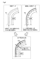
- FIG. 7 is a diagram illustrating the calculation of the control margin
- FIG. 8 is a diagram 1 showing a specific example of the control margin
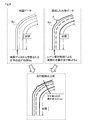
- FIG. 9 is a second diagram illustrating a specific example of the control margin
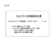
- FIG. 10 is a diagram for explaining the calculation of the landmark margin.
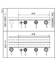
- FIG. 11 is a diagram 1 showing a specific example of the landmark margin
- FIG. 12 is a second diagram illustrating a specific example of the landmark margin.
- FIG. 2 showing the overall configuration of this system
- the vehicles 1 to 3 have an automatic driving system or a driving support system, and perform driving control using vehicle probe data and map data.
- the vehicles 1 to 3 have a communication function, and collect only map data from the detected vehicle probe data, which is determined to be vehicle probe data that needs to be updated as described later.
- the data is transmitted to the server 4a of the center 4.
- the map data collection center 4 transmits the received vehicle probe data to the server 5a of the map data update center 5.
- the map data updating center 5 executes a process of updating the map data corresponding to the latest situation based on the vehicle probe data transmitted in this manner.
- the latest map data updated and created by the map data update center 5 is obtained by using a medium such as a DVD or by using a communication function to provide the latest map data. State.
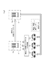
- the in-vehicle device 10 includes a calculation unit 11 and a determination unit 12 as functional blocks.
- the calculation unit 11 includes an external situation recognition unit 11a, a vehicle position identification unit / landmark margin calculation unit 11b, a map data acquisition / storage unit 11c, and a data difference detection unit / difference calculation unit 11d.
- the determination unit 12 includes a difference upload determination unit 12a and a control / function realization unit / control margin calculation unit 12b.
- the in-vehicle device 10 actually has a configuration mainly including a CPU, and achieves the functions of the calculation unit 11 and the determination unit 12 based on a program stored therein.
- a sensor 20 is connected to the vehicle-mounted device 10.
- a camera 20a for photographing the outside of the vehicle a radar 20b, a LiDAR (Light Detection and Ranging / Laser Imaging Detection and Ranging) 20c, an ultrasonic sensor 20c, and the like are provided.
- the calculation unit 11 analyzes the sensor data and calculates the vehicle data as vehicle probe data indicating an external situation.
- the camera 20a captures an image of the front and surroundings outside the vehicle and outputs video information as sensor data.
- the radar 20b and the LiDAR 20c detect a situation in front of and around the vehicle and a distance to a feature and output the sensor data.
- the ultrasonic sensor 20d outputs an ultrasonic wave to detect whether or not an object exists at a portion facing the ultrasonic sensor, and outputs the detected data as sensor data.
- the communication unit 30 performs communication between the in-vehicle device 10 and the outside.
- the communication unit 30 communicates with the map data collection center 4 described above, and the vehicle probe to be transmitted determined by the in-vehicle device 10 as described later. Send data.
- the communication unit 30 communicates with the above-described map data update center 5 to download updated latest map data or to receive necessary map data each time.
- the recognized feature data storage unit 40 stores the data of the feature recognized by the vehicle-mounted device 10 and is read out and used by the vehicle-mounted device 10 as needed.
- the map data storage unit 60 stores and holds the latest map data downloaded from the server 5a of the map data update center 5 by the communication device 30.
- the map data may be stored in a medium such as a DVD.
- the map data updated by the map data update center 5 may be sequentially downloaded and stored as the latest map data. Can also be retained.
- the control output device 60 is a control device for controlling the traveling of the vehicles 1 to 3, and performs the traveling control of the own vehicle in accordance with the traveling control command created by the vehicle-mounted device 10.
- the on-vehicle device 10 In the automatic driving / driving support mode, the on-vehicle device 10 generates a driving control command based on the information captured by the sensor 20, and in this case, realizes high-precision driving control by referring to map data as necessary. Is what you do.
- the vehicles 1 to 3 are equipped with an automatic driving / driving support system.
- the role of map data is an important factor.
- an automatic driving / driving support system using map data first, the position of the own vehicle on the map data is specified.
- the map data is used to determine where the own vehicle position exists on the map data. It is possible to take a method of specifying with high accuracy. Specifically, it is specified by comparing features present on the map data with surrounding information obtained from the sensor 20 and other various on-vehicle sensors.
- the map data around the position of the own vehicle assumed from the GNSS information is acquired, and the position of the own vehicle on the map data is determined based on the shape of the road, that is, the lane and the sign position in the map data. Can be calculated and specified.
- control / functions cannot be realized only with information on the surroundings obtained from various sensors mounted on the vehicle, and map data is used in such a case.
- the vehicle-mounted sensor it may be difficult for the vehicle-mounted sensor to recognize the shape of the front lane due to a weather condition in which the visibility in the front becomes poor due to rain or snow.
- the recognition result of the on-vehicle sensor is complemented using the map data, and the function of traveling while holding the center of the lane can be continued without interruption.
- any means may be used to supply the map data from the map data update center 5 to the vehicle-mounted device 10, and the means can be classified as follows.
- the data is captured and stored in the storage unit 10c or the map data storage unit 50 of the vehicle-mounted device 10.
- the map data of the medium is read by the in-vehicle device 10 as needed with the medium mounted.
- the communication unit 30 the data is stored in the storage unit 10 c or the map data storage unit 50 in the vehicle-mounted device 10 via a telephone communication network, Wi-Fi, Bluetooth (registered trademark), or other wireless communication. I do.
- the map data held in the on-vehicle device 10 or the map data storage unit 50 may be stored nationwide, or only the map data around the place where the on-vehicle devices 10 of the vehicles 1 to 3 exist. It may be memorized.
- the storage unit 10c and the map data storage unit 50 may be stored semi-permanently and reused, or a method of requesting the map data update center 5 to obtain and use it every time it is used. Can also be adopted.
- the map data used by the vehicle-mounted device 10 as a basis for comparison is used. Is desirably as fresh as possible. Therefore, it is preferable that the communication unit 30 using a telephone communication network or the like always obtain the latest map data and use it as a basis for comparison. This is because permanent use of old map data as a comparison source tends to increase the gap between the map data and the external situation in the real world, and reduces the traffic of uploaded vehicle probe data. Because it does not match.
- the on-vehicle device 10 recognizes as a real world situation, that is, an external situation, based on the sensor data detected by the sensor 20 as follows. This is vehicle probe data required for vehicle control, and determines whether or not to transmit to the map data collection center 4 as necessary.
- the targets are paints drawn on the road surface, such as road lane paint, pedestrian crossings, stop lines, divergence zones, restriction arrows, and other information used for traffic control and traffic regulation drawn on the road. is there.
- Some of the objects provided as objects include, for example, signs for regulations, warnings, guidance, assistance, traffic lights, and other objects that can be landmarks used by the vehicle-mounted device to identify its own position.
- the position, form, meaning, and the like of the target described above are calculated by the calculation unit 11 of the vehicle-mounted device 20.
- This is, for example, the three-dimensional position of the paint, white or yellow for road lane paint, and the three-dimensional position of the sign itself, the height and width of the sign, The three-dimensional position of the support, the type of sign, the meaning of the sign, and the like.
- the camera 20a, the radar 20b, the LiDAR 20c, the ultrasonic sensor 20d, and the like are provided as the sensor 20 for recognizing such external information. Note that all of these may not be provided, and may be provided selectively. Then, by combining the sensor data detected by the sensor 20, GNSS information, and other vehicle information such as speed, it is possible to recognize an external situation.
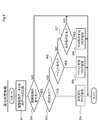
- map data processing by the vehicle-mounted device 10 will be described with reference to FIGS.
- the description will be made as a content to be executed by the vehicle-mounted device 10 as a whole, the operation is functionally shared by the calculation unit 11 and the determination unit 12.
- the vehicle 10 is in a state where the vehicle 1 is performing automatic traveling control.
- the vehicle-mounted device 10 specifies the current position in step A1.
- the on-vehicle device 10 calculates and specifies the current position by the own vehicle position specifying unit / landmark margin calculating unit 11b based on the GNSS information received via the communication unit 30. Here, the position on the map is roughly acquired.
- the in-vehicle device 10 reads map data from the map data storage unit 50 in step A2.
- the in-vehicle device 10 reads the map data of the area centered on the current position specified in step A1 from the map data storage unit 50 by the map data acquisition / storage unit 11c.
- the in-vehicle device 10 performs a process of recognizing the external situation in step A3.
- the in-vehicle device 10 first receives data on the external situation from the camera 20a, the radar 20b, the LiDAR 20c, the ultrasonic sensor 20d constituting the sensor 20, and the sensors mounted on other vehicles by the external situation recognition unit 11a. take in.
- the on-vehicle device 10 determines whether the external situation recognition unit 11a paints the lane of the road with the paint drawn on the road surface, a pedestrian crossing, a stop line, a guideway, a regulation arrow, and other traffic control and drawing drawn on the road. In addition to recognizing information and the like used for traffic regulation, it also recognizes a sign provided as an object, a traffic signal, and a landmark used by an in-vehicle device to identify its own position. Thereafter, the on-vehicle device 10 stores the recognized feature data recognized by the external situation recognition unit 11a in Step A4 in the recognized feature data storage unit 40.
- the on-vehicle device 10 performs a deterioration determination process in Step A5.
- the deterioration information obtained by this processing is not included in the data detected as a difference between the recognized feature data and the map data, and is not intentionally uploaded to the map data collection center 4 as vehicle probe data, or when the upload is performed. It is determined to add a “deterioration flag” and transmit.
- the paint on the road such as the lane markings
- the fading or disappearance due to the deterioration of the paint drawn on the road is compared with the value of the recognition confidence when the vehicle-mounted device 10 recognizes the lane paint on the road and the lane paint position on the map data.
- Lane paint exists on the map data, and the recognition result of the in-vehicle device 10 lowers the recognition confidence of the lane paint. Since the lane paint falls below the threshold, it is determined that the lane cannot be detected. As a result, the map data and If it is concluded that a difference has occurred in the external situation, it is determined that "paint deterioration" has occurred, and a "deterioration flag" is added when recording as difference information.
- the map data update center 5 sets a threshold value for changing the data of the difference information to which the “deterioration flag” is added, higher than other threshold values. That is, even if the lane paint is faded and disappears and it does not look realistic, it is determined that the lane paint should be there originally, and the data is left on the map data, so that the in-vehicle device 10 This is because there is a possibility that it can be used for the control of
- the specific content of the deterioration determination process is performed by the external situation recognition unit 11a according to the procedure shown in FIG.
- the in-vehicle device 10 compares the recognized feature data with the map data in step B1. On the basis of the comparison result, the in-vehicle device 10 determines whether or not there is a change in the recognized feature in Step B2. If “NO”, the process ends with no change determination.
- the in-vehicle device 10 determines in a next step B3 whether or not the change state is due to shape deterioration such as a case where the position is changed due to bending of the sign, and “YES” is determined. In the case of, a "deterioration flag" for shape deterioration is set.
- the in-vehicle device 10 proceeds to a step B4.
- the on-vehicle device 10 determines whether the change state is due to paint deterioration such as a case where the paint on the road is rubbed or disappeared due to deterioration. If “YES”, the “deterioration” of the paint deterioration is determined. Flag ".
- step B2 determines in step B2 whether there is a change, and if neither the shape deterioration nor the paint deterioration has occurred.
- step B7 determines in step B7 whether or not there is any other deterioration.
- step B8 sets other "deterioration flags”. If “NO” in the step B7, the in-vehicle device 10 determines that the content of the change is an intentional change and not due to deterioration. The in-vehicle device 10 terminates the process of the deterioration determination, and proceeds to the next step A6 assuming that step A5 in FIG. 3 has been completed.
- step A6 the in-vehicle device 10 considers the map data and the recognized feature data obtained as described above, and the control / function realization unit / control allowance calculation unit 12b of the determination unit 12 performs automatic driving.
- the control function is executed and output to the control output device 60.
- the in-vehicle device 10 first calculates the difference Vd by comparing the map data with the recognized external situation in the data difference detection unit / difference calculation unit 11d of the calculation unit 11 in step A7. .
- the data difference detection unit / difference degree calculation unit 11d of the on-vehicle device 10 converts the degree of difference between the recognized real world situation and the held map data into numerical information as the difference degree Vd as described above. Is calculated as
- the data difference detection unit / difference degree calculation unit 11d calculates, for each type, a range in which the vehicle travels a certain distance, that is, an external situation detected during the determination section, as the difference degree Vd. .
- the determination level of the difference degree Vd is set to a different level for each type. For example, the determination level of the marker position is set to less than 75%. Specifically, if there is a mismatch at one of the four markers, it is acceptable. Also, the determination level of the stop line is set to 100%, and uploading is performed when there is a position mismatch even at one location.
- the determination level of the degree of difference Vd is determined by the use of the map data in the vehicle-mounted device 10.
- the reason why the determination level of the sign position is low is that the position of the sign is used for specifying the own vehicle position in the map data, and is not a processing by one sign but a plurality of sign positions. This is because comprehensive processing and determination are performed.
- the position of the stop line when used to specify the position of the own vehicle, the front / rear position determination can be very clearly processed. May give.
- the shift of the stop line position in the map data may be caused by uncertain external situation recognition in the vehicle-mounted device 10, for example, due to bad weather. This is because if the recognition is difficult or if the vehicle cannot be seen by a preceding vehicle or the like, it may not function properly.
- step A8 the vehicle-mounted device 10 determines whether or not the value of the calculated difference Vd can be regarded as substantially zero in consideration of the error. If “NO” here, that is, if the difference degree Vd cannot be regarded as zero, the in-vehicle device 10 proceeds to step A9, and calculates the control allowance Vmc and the landmark allowance Vml.
- control margin is an index indicating a margin when the vehicle-mounted device 10 performs the vehicle control.
- the result of the vehicle control based on information read in advance from the map data is compared with the result of the vehicle control in consideration of the external situation.
- the external situation is preferentially used.
- the content to be compared may be the amount of deviation of the vehicle from the center of the lane, the lateral acceleration of the vehicle, and the like.
- step A8 the in-vehicle device 10 ends the process via step A13.
- step A13 the vehicle-mounted device 10 determines that uploading to the map data collection center 4 is not to be performed because the difference Vd to be determined can be regarded as substantially zero.
- the in-vehicle device 10 determines whether the control allowance Vmc is larger than the predetermined threshold Nmc and the landmark allowance Vml is larger than the predetermined threshold Nml. If "NO" in the step A10, that is, if both the control margin Vmc and the landmark margin Vml are equal to or smaller than the threshold, the on-vehicle device 10 proceeds to the step A11.
- the vehicle-mounted device 10 determines both the control allowance Vmc and the landmark allowance Vml during the vehicle control.
- the vehicle control is not performed, only the landmark margin Vml is determined.
- step A11 the vehicle-mounted device 10 performs a process of uploading the difference information calculated based on the sensor data as vehicle probe data including the above-described deterioration flag. Thereby, the vehicle-mounted device 10 transmits the vehicle probe data to the server 4a of the map data collection center 4 via the communication unit 30.
- step A10 determines “YES”, shifts to step A11, and performs a process of uploading as vehicle probe data.
- step A13 the in-vehicle device 10 ends the process via the step A13.
- the vehicle probe data is displayed on the map.
- the communication volume can be reduced.
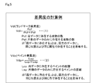
- the degree of difference Vd is set for each type.
- the degree of difference relating to a landmark or a feature is Vdl
- the degree of difference relating to paint is Vdp.
- the landmark difference Vdl is calculated as shown in equation (1) in FIG.
- the number of features that is, the number of landmarks existing in both the recognized feature data and the map data is Pcf
- the number of features existing only in one of the data is Psf.
- the feature existing in both means that it exists in the same position and the same attribute in both data.
- the paint difference degree Vdp is calculated as shown by the equation (2) in FIG.
- the distance of the paint existing in both the recognized feature data and the map data is Lcp
- the distance of the paint existing in only one of the data is Lsp.
- “present in both data” means that both data exist in the same position and in the same color.
- FIG. 6 shows a specific example.
- FIG. 6A shows map data obtained by downloading or the like on the vehicle side.
- the paints P1 to P5 separating the lanes and the four labels L1 to L4 are shown.
- FIG. 6B shows the feature data recognized by the vehicle-mounted device 10 by the sensor 20 or the like.
- the vehicle travels on a track indicated by a broken line with an arrow, and paints P1, P2 and three signs L2 to L4 are present around the travel locus.
- the paint P2 is a lane paint of a lane adjacent to the traveling lane of the own vehicle, and is shown as paint P2a in which an undetected portion exists ahead.
- FIG. 6 (c) shows the result of extracting the surrounding data of the traveling locus of the vehicle shown in FIG. 6 (b) from the map data.
- paints P1, P2 and four markers L1 to L4 are extracted.
- step A7 of the processing of FIG. 3 described above is executed to calculate the degree of difference Vd
- the degree of difference Vd is obtained as shown in FIG.
- the left column shows the difference data.
- the marker L1 that was present only in the map data is shown, and the other markers L2 to L4 are not displayed as differences because they are common data.
- the paint there is a difference in the paint P2, and a portion that has not been detected in the recognized feature data is displayed as a difference.
- the landmark difference degree Vdl can be calculated by the following equation (1) because the number of features Pcf existing in both data is three and the number of features Psf existing only in one data is one.
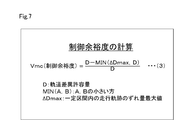
- control allowance Vcm is used to quantify a difference between a traveling locus assumed from the map data and a locus traveled by actual vehicle control.
- the control allowance Vcm is calculated as shown by equation (3) in FIG.
- D is the allowable amount of trajectory difference in a certain section
- ⁇ D is the deviation amount of the running trajectory from the estimated trajectory in the certain section
- ⁇ Dmax is the maximum value in that section.
- the operator MIN (A, B) takes the smaller value of the numbers A and B in parentheses.
- the margin Vcm may be obtained as a value larger than zero even if there is a difference between the two.
- the on-vehicle device 10 is able to perform vehicle control in a marginal state, and the vehicle having such a degree of difference is generated. It is understood that it is not necessary to transmit the probe data to the map data collection center 4.
- FIGS. 8 and 9 show specific examples 1 and 2.
- FIG. 8 showing Specific Example 1 the map data of the road acquired by downloading or the like on the vehicle side is shown in the upper left, and the traveling locus Sc of the own vehicle assumed from the map data is shown by a dotted line in the figure.
- the road feature data recognized by the vehicle-mounted device 10 by the sensor 20 or the like is shown in the upper right of FIG. 8.
- the curve shape of the recognized road is gentler than the curve shape of the map data.
- the actual traveling locus Sa of the own vehicle that has traveled by the lane holding control from the paint indicating the traveling lane is shown in the figure.
- FIG. 9 showing Specific Example 2, the map data similar to that in FIG. 8 is shown in the upper left, and the traveling locus Sc of the own vehicle assumed from the map data is shown by a dotted line in the figure.
- road feature data recognized by the vehicle-mounted device 10 by the sensor 20 or the like is shown on the upper right of FIG. 9, road feature data recognized by the vehicle-mounted device 10 by the sensor 20 or the like is shown.
- a retreat area X is provided outside the curve.
- the actual traveling locus Sa of the own vehicle that has traveled by the lane holding control from the paint indicating the traveling lane is shown in the figure.
- the traveling locus Sc estimated from the map data in a certain section and the actual traveling locus Sa of the own vehicle are shown in a superimposed state for comparison.
- a plurality ( ⁇ D1 to ⁇ Dn) of deviations ⁇ D between the estimated travel locus Sc and the actual travel locus Sa of the own vehicle are calculated in the section, and the largest one of them is ⁇ Dmax. As shown.
- the vehicle position is identified even if there is a slight shift in order to recognize a plurality of landmarks, that is, signs, and match the map data. It is common to design the control function to have robustness so that it can be performed. However, if the landmark recognized by the vehicle-mounted device 10 cannot be used or cannot be recognized, it is virtually checked and evaluated whether or not the own vehicle position has been correctly specified.
- the map data referred to and recognized by the control margin Vmc and the landmark margin Vml are different from each other, only the relevant difference information is uploaded when the vehicle probe data is uploaded to the map data collection center 4 as the difference information by the margin judgment. By doing so, the amount of communication can be suppressed. Therefore, for example, when the control allowance Vmc is higher than the threshold value but the landmark allowance Vml is equal to or less than the threshold value, only the vehicle probe data indicating the difference information related to the landmark is uploaded to the map data collection center 4.
- FIG. 11 A calculation example of the landmark margin Vml will be described with reference to FIGS.
- signs L0 to L4 are shown on the left side as four landmark roads as landmarks indicated by map data.
- a traveling lane and markers L1 to L4 are shown as landmarks indicating feature data recognized in the section.
- the feature data recognized in the section is the four markers L1 to L4, which match the markers L1 to L4 in the map data, and the position can be specified by the vehicle-mounted device 10.
- the landmark margin Vml is calculated.
- the on-board unit 10 can specify the position. As described above, the number of recognized landmarks RLM is four. As shown in FIG. 12, assuming that there is one unrecognizable feature data, there are four cases as shown in the figure, but in any of these cases, the vehicle-mounted device 10 can specify the position. . Similarly, assuming that there is two unrecognizable feature data, FIG. 12 shows two examples, and there are six cases. In these cases, the vehicle-mounted device 10 also specifies the position. can do.
- the vehicle-mounted device 10 cannot determine the position. Becomes Therefore, in this case, the number LLM of self-position specifying limit landmarks of the vehicle-mounted device 10 in the section is two.
- the in-vehicle device 10 is provided with the calculation unit 11 and the determination unit 12, and even when there is a difference between the map data and the vehicle probe data of the recognized feature, the determination unit 12 determines the vehicle In the case of the range of controllable values in which the traveling control can be performed based on the map data and the vehicle probe data, the vehicle probe data does not need to be transmitted for updating the map data. It can be reduced.
Landscapes
- Engineering & Computer Science (AREA)
- Remote Sensing (AREA)
- Radar, Positioning & Navigation (AREA)
- Physics & Mathematics (AREA)
- General Physics & Mathematics (AREA)
- Automation & Control Theory (AREA)
- Human Computer Interaction (AREA)
- Transportation (AREA)
- Mechanical Engineering (AREA)
- Traffic Control Systems (AREA)
- Navigation (AREA)
Priority Applications (3)
| Application Number | Priority Date | Filing Date | Title |
|---|---|---|---|
| DE112019004285.8T DE112019004285T5 (de) | 2018-08-31 | 2019-08-27 | Bordvorrichtung |
| CN201980056622.7A CN112639906B (zh) | 2018-08-31 | 2019-08-27 | 车载器以及判定方法 |
| US17/186,910 US20210180963A1 (en) | 2018-08-31 | 2021-02-26 | Onboard device |
Applications Claiming Priority (2)
| Application Number | Priority Date | Filing Date | Title |
|---|---|---|---|
| JP2018-163078 | 2018-08-31 | ||
| JP2018163078A JP7001024B2 (ja) | 2018-08-31 | 2018-08-31 | 車載機 |
Related Child Applications (1)
| Application Number | Title | Priority Date | Filing Date |
|---|---|---|---|
| US17/186,910 Continuation US20210180963A1 (en) | 2018-08-31 | 2021-02-26 | Onboard device |
Publications (1)
| Publication Number | Publication Date |
|---|---|
| WO2020045426A1 true WO2020045426A1 (ja) | 2020-03-05 |
Family
ID=69644312
Family Applications (1)
| Application Number | Title | Priority Date | Filing Date |
|---|---|---|---|
| PCT/JP2019/033512 Ceased WO2020045426A1 (ja) | 2018-08-31 | 2019-08-27 | 車載機 |
Country Status (5)
| Country | Link |
|---|---|
| US (1) | US20210180963A1 (enExample) |
| JP (1) | JP7001024B2 (enExample) |
| CN (1) | CN112639906B (enExample) |
| DE (1) | DE112019004285T5 (enExample) |
| WO (1) | WO2020045426A1 (enExample) |
Cited By (1)
| Publication number | Priority date | Publication date | Assignee | Title |
|---|---|---|---|---|
| WO2021254730A1 (de) * | 2020-06-15 | 2021-12-23 | Volkswagen Aktiengesellschaft | Verfahren zum bewerten einer digitalen karte, sowie bewertungssystem |
Families Citing this family (4)
| Publication number | Priority date | Publication date | Assignee | Title |
|---|---|---|---|---|
| WO2021003455A1 (en) * | 2019-07-02 | 2021-01-07 | DeepMap Inc. | Determining localization confidence of vehicles based on convergence ranges |
| CN112257724B (zh) * | 2020-10-26 | 2022-09-20 | 武汉中海庭数据技术有限公司 | 一种道路外侧线置信度评估方法及系统 |
| JP7484837B2 (ja) | 2021-07-13 | 2024-05-16 | トヨタ自動車株式会社 | 地物データ収集装置、地物データ収集方法及び地物データ収集用コンピュータプログラム |
| CN119252022B (zh) * | 2024-09-26 | 2025-12-02 | 浙江大学 | 一种多层次嵌入的基于预训练大语言模型的交通流时空预测方法 |
Citations (5)
| Publication number | Priority date | Publication date | Assignee | Title |
|---|---|---|---|---|
| JP2005241373A (ja) * | 2004-02-25 | 2005-09-08 | Matsushita Electric Ind Co Ltd | 地図情報更新システム、地図情報提供装置 |
| JP2009157617A (ja) * | 2007-12-26 | 2009-07-16 | Toyota Motor Corp | 交通情報配信システム並びにそのシステムを構成するプローブ情報生成装置及び交通情報配信装置 |
| JP2013140448A (ja) * | 2011-12-28 | 2013-07-18 | Fujitsu Ltd | 路面調査プログラム及び路面調査装置 |
| JP2016180980A (ja) * | 2015-03-23 | 2016-10-13 | 株式会社豊田中央研究所 | 情報処理装置、プログラム、及び地図データ更新システム |
| JP2017087816A (ja) * | 2015-11-04 | 2017-05-25 | トヨタ自動車株式会社 | 自動運転システム |
Family Cites Families (14)
| Publication number | Priority date | Publication date | Assignee | Title |
|---|---|---|---|---|
| JP2002319087A (ja) * | 2001-04-18 | 2002-10-31 | Mazda Motor Corp | 車両運転特性診断方法、車両運転特性診断システム、車両運転特性診断装置、車両制御用装置及びそのコンピュータ・プログラム |
| JP4812415B2 (ja) * | 2005-11-30 | 2011-11-09 | 富士通株式会社 | 地図情報更新システム、中央装置、地図情報更新方法、及びコンピュータプログラム |
| JP4730165B2 (ja) | 2006-03-27 | 2011-07-20 | 株式会社デンソー | 交通情報管理システム |
| JP5898539B2 (ja) * | 2012-03-22 | 2016-04-06 | 本田技研工業株式会社 | 車両走行支援システム |
| KR101365498B1 (ko) * | 2012-09-06 | 2014-03-13 | 주식회사 만도 | 차량의 주차 보조 시스템 및 그 제어방법 |
| JP6082415B2 (ja) | 2015-03-03 | 2017-02-15 | 富士重工業株式会社 | 車両の走行制御装置 |
| US9891057B2 (en) * | 2015-03-23 | 2018-02-13 | Kabushiki Kaisha Toyota Chuo Kenkyusho | Information processing device, computer readable storage medium, and map data updating system |
| DE112016004370B4 (de) * | 2015-10-16 | 2025-03-06 | Hitachi Astemo, Ltd. | Fahrzeugsteuerung und Fahrzeugsteuervorrichtung |
| CN105258735A (zh) * | 2015-11-12 | 2016-01-20 | 杨珊珊 | 基于无人飞行器的环境数据检测方法及环境数据检测装置 |
| JP6654923B2 (ja) | 2016-02-16 | 2020-02-26 | 株式会社Subaru | 地図情報出力装置 |
| CN107662558B (zh) * | 2016-07-27 | 2020-04-03 | 上海博泰悦臻网络技术服务有限公司 | 一种基于车外环境数据的辅助驾驶方法及装置 |
| US10794711B2 (en) * | 2016-12-30 | 2020-10-06 | DeepMap Inc. | High definition map updates based on sensor data collected by autonomous vehicles |
| CN106980654B (zh) * | 2017-03-06 | 2019-02-12 | Oppo广东移动通信有限公司 | 路况更新方法、装置及计算机设备 |
| JP2018163078A (ja) | 2017-03-27 | 2018-10-18 | シチズン時計株式会社 | てん輪 |
-
2018
- 2018-08-31 JP JP2018163078A patent/JP7001024B2/ja active Active
-
2019
- 2019-08-27 CN CN201980056622.7A patent/CN112639906B/zh active Active
- 2019-08-27 WO PCT/JP2019/033512 patent/WO2020045426A1/ja not_active Ceased
- 2019-08-27 DE DE112019004285.8T patent/DE112019004285T5/de not_active Ceased
-
2021
- 2021-02-26 US US17/186,910 patent/US20210180963A1/en not_active Abandoned
Patent Citations (5)
| Publication number | Priority date | Publication date | Assignee | Title |
|---|---|---|---|---|
| JP2005241373A (ja) * | 2004-02-25 | 2005-09-08 | Matsushita Electric Ind Co Ltd | 地図情報更新システム、地図情報提供装置 |
| JP2009157617A (ja) * | 2007-12-26 | 2009-07-16 | Toyota Motor Corp | 交通情報配信システム並びにそのシステムを構成するプローブ情報生成装置及び交通情報配信装置 |
| JP2013140448A (ja) * | 2011-12-28 | 2013-07-18 | Fujitsu Ltd | 路面調査プログラム及び路面調査装置 |
| JP2016180980A (ja) * | 2015-03-23 | 2016-10-13 | 株式会社豊田中央研究所 | 情報処理装置、プログラム、及び地図データ更新システム |
| JP2017087816A (ja) * | 2015-11-04 | 2017-05-25 | トヨタ自動車株式会社 | 自動運転システム |
Cited By (3)
| Publication number | Priority date | Publication date | Assignee | Title |
|---|---|---|---|---|
| WO2021254730A1 (de) * | 2020-06-15 | 2021-12-23 | Volkswagen Aktiengesellschaft | Verfahren zum bewerten einer digitalen karte, sowie bewertungssystem |
| CN115698630A (zh) * | 2020-06-15 | 2023-02-03 | 大众汽车股份公司 | 用于评价数字地图的方法以及评价系统 |
| CN115698630B (zh) * | 2020-06-15 | 2025-11-07 | 大众汽车股份公司 | 用于评价数字地图的方法以及评价系统 |
Also Published As
| Publication number | Publication date |
|---|---|
| CN112639906B (zh) | 2023-01-20 |
| JP7001024B2 (ja) | 2022-01-19 |
| CN112639906A (zh) | 2021-04-09 |
| US20210180963A1 (en) | 2021-06-17 |
| DE112019004285T5 (de) | 2021-07-08 |
| JP2020035321A (ja) | 2020-03-05 |
Similar Documents
| Publication | Publication Date | Title |
|---|---|---|
| JP7149244B2 (ja) | 自律車両用の交通信号応答 | |
| CN101351685B (zh) | 自身车辆位置测定装置 | |
| JP4370869B2 (ja) | 地図データ更新方法および地図データ更新装置 | |
| JP4724043B2 (ja) | 対象物認識装置 | |
| JP4938351B2 (ja) | 車両用測位情報更新装置 | |
| WO2020045426A1 (ja) | 車載機 | |
| CN102208011B (zh) | 图像处理系统及车辆控制系统 | |
| CN101091103B (zh) | 图像识别装置和方法以及使用该图像识别装置或方法的定位装置、车辆控制装置和导航装置 | |
| CN110471406B (zh) | 自动驾驶系统 | |
| JP6941178B2 (ja) | 自動運転制御装置及び方法 | |
| JP2012185076A (ja) | 速度規制値通知装置及び速度規制値通知システム | |
| US12054144B2 (en) | Road information generation apparatus | |
| JP4979644B2 (ja) | ナビゲーション装置および車両の走行安全装置 | |
| CN116639146A (zh) | 驾驶辅助方法和驾驶辅助系统 | |
| JP5499815B2 (ja) | 走行道路推定システム | |
| KR102158169B1 (ko) | 차선 인식장치 | |
| JP7583649B2 (ja) | 地図生成装置および車両位置認識装置 | |
| JP4775658B2 (ja) | 地物認識装置・自車位置認識装置・ナビゲーション装置・地物認識方法 | |
| JP4724079B2 (ja) | 対象物認識装置 | |
| JP7362800B2 (ja) | 車両制御装置 | |
| JP2007102578A (ja) | 距離算出装置及び距離算出方法並びにその装置を有する車両 | |
| CN116892906A (zh) | 地图可靠度判定装置和驾驶辅助装置 | |
| JP2006344133A (ja) | 道路区画線検出装置 | |
| CN113247021A (zh) | 车辆控制方法、系统、电子设备及计算机可读存储介质 | |
| JP7467522B2 (ja) | 車両制御装置 |
Legal Events
| Date | Code | Title | Description |
|---|---|---|---|
| 121 | Ep: the epo has been informed by wipo that ep was designated in this application |
Ref document number: 19854538 Country of ref document: EP Kind code of ref document: A1 |
|
| 122 | Ep: pct application non-entry in european phase |
Ref document number: 19854538 Country of ref document: EP Kind code of ref document: A1 |