WO2020045277A1 - ロボット及びその原点位置調整方法 - Google Patents
ロボット及びその原点位置調整方法 Download PDFInfo
- Publication number
- WO2020045277A1 WO2020045277A1 PCT/JP2019/033025 JP2019033025W WO2020045277A1 WO 2020045277 A1 WO2020045277 A1 WO 2020045277A1 JP 2019033025 W JP2019033025 W JP 2019033025W WO 2020045277 A1 WO2020045277 A1 WO 2020045277A1
- Authority
- WO
- WIPO (PCT)
- Prior art keywords
- origin
- posture
- robot
- robot arm
- end effector
- Prior art date
- Legal status (The legal status is an assumption and is not a legal conclusion. Google has not performed a legal analysis and makes no representation as to the accuracy of the status listed.)
- Ceased
Links
Images

Classifications
-
- B—PERFORMING OPERATIONS; TRANSPORTING
- B25—HAND TOOLS; PORTABLE POWER-DRIVEN TOOLS; MANIPULATORS
- B25J—MANIPULATORS; CHAMBERS PROVIDED WITH MANIPULATION DEVICES
- B25J9/00—Program-controlled manipulators
- B25J9/16—Program controls
- B25J9/1679—Program controls characterised by the tasks executed
- B25J9/1692—Calibration of manipulator
-
- B—PERFORMING OPERATIONS; TRANSPORTING
- B25—HAND TOOLS; PORTABLE POWER-DRIVEN TOOLS; MANIPULATORS
- B25J—MANIPULATORS; CHAMBERS PROVIDED WITH MANIPULATION DEVICES
- B25J13/00—Controls for manipulators
- B25J13/08—Controls for manipulators by means of sensing devices, e.g. viewing or touching devices
-
- B—PERFORMING OPERATIONS; TRANSPORTING
- B25—HAND TOOLS; PORTABLE POWER-DRIVEN TOOLS; MANIPULATORS
- B25J—MANIPULATORS; CHAMBERS PROVIDED WITH MANIPULATION DEVICES
- B25J19/00—Accessories fitted to manipulators, e.g. for monitoring, for viewing; Safety devices combined with or specially adapted for use in connection with manipulators
- B25J19/02—Sensing devices
- B25J19/04—Viewing devices
-
- B—PERFORMING OPERATIONS; TRANSPORTING
- B25—HAND TOOLS; PORTABLE POWER-DRIVEN TOOLS; MANIPULATORS
- B25J—MANIPULATORS; CHAMBERS PROVIDED WITH MANIPULATION DEVICES
- B25J9/00—Program-controlled manipulators
- B25J9/16—Program controls
- B25J9/1612—Program controls characterised by the hand, wrist, grip control
-
- B—PERFORMING OPERATIONS; TRANSPORTING
- B25—HAND TOOLS; PORTABLE POWER-DRIVEN TOOLS; MANIPULATORS
- B25J—MANIPULATORS; CHAMBERS PROVIDED WITH MANIPULATION DEVICES
- B25J9/00—Program-controlled manipulators
- B25J9/16—Program controls
- B25J9/1656—Program controls characterised by programming, planning systems for manipulators
- B25J9/1664—Program controls characterised by programming, planning systems for manipulators characterised by motion, path, trajectory planning
-
- B—PERFORMING OPERATIONS; TRANSPORTING
- B25—HAND TOOLS; PORTABLE POWER-DRIVEN TOOLS; MANIPULATORS
- B25J—MANIPULATORS; CHAMBERS PROVIDED WITH MANIPULATION DEVICES
- B25J9/00—Program-controlled manipulators
- B25J9/16—Program controls
- B25J9/1694—Program controls characterised by use of sensors other than normal servo-feedback from position, speed or acceleration sensors, perception control, multi-sensor controlled systems, sensor fusion
- B25J9/1697—Vision controlled systems
Definitions
- the present invention relates to a robot having a plurality of joints and an origin position adjusting method thereof.
- an industrial robot includes a robot arm having a plurality of links connected via a joint, an end effector connected to the end of the robot arm via a joint, a base supporting the robot arm, and a robot arm. And a controller that controls the operation of the end effector.
- the robot as described above has a predetermined origin posture, and the rotation position in the origin posture for each joint is the origin position (ie, 0 deg).
- the origin position ie, 0 deg.
- the robot arm or end effector collides with another object or the robot has been used for many years, the axis of the joint is shifted, and the robot does not return to the home position even if each joint is returned to the home position. Sometimes. In such a case, it is necessary to adjust the origin position of each joint.
- an origin position adjustment method for example, a method using a dedicated jig for origin position adjustment disclosed in Patent Document 1 is known.
- a robot arm or an end effector is fixed at an origin posture using a jig, and the rotational position of each joint in that state is stored as an origin position.
- an origin position adjustment method for example, a method using a non-contact sensor disclosed in Patent Document 2 is known.
- a light source is provided on the base
- a light receiver is provided on the arm
- the origin position is set when the light beam emitted from the light source can be detected by the light receiver, and a preset origin position when the robot is in the original position.
- the position deviation and the amount of displacement of the rotational position of the arm (joint) from the position are calculated, and the origin position of the arm is calibrated based thereon.
- a jig or a sensor dedicated to the origin position adjustment as described in Patent Documents 1 and 2 is used.
- the housing must be opened in order to attach and detach jigs and sensors.
- the robot is contaminated.
- decontamination after adjusting the origin position is complicated.
- the present invention has been made in view of the above circumstances, and an object of the present invention is to provide a robot that automatically adjusts the origin position without requiring attachment / detachment of a dedicated jig or sensor for origin position adjustment. It is in.
- the robot includes: A robot arm having a plurality of links connected via joints; An end effector connected to the tip of the robot arm via a wrist joint; The rotational position of the joint and the wrist joint when the end effector and the robot arm are in a predetermined origin posture is set as the origin position, and the entire end effector and the robot arm having the origin posture are included in the imaging range.
- a deviation of the current posture of the end effector and the robot arm from the original posture is determined, and the presence or absence of a deviation of the original position is determined based on the deviation. I have.
- a robot arm having a plurality of links connected via a joint, an end effector connected to a distal end of the robot arm via a wrist joint, and a robot when the end effector and the robot arm are in a predetermined origin posture.
- An imaging device attached to the end effector or the robot arm such that the rotational position of the joint and the wrist joint is the origin position, and the imaging range includes the end effector and the robot arm in the origin posture.
- a method for adjusting the origin position of a robot Setting the rotational position of the joint and the wrist joint to the origin position; Imaging by the imaging device and acquiring the captured image; By comparing the captured image with the reference posture image representing the end effector and the robot arm of the reference posture, the deviation of the current posture of the end effector and the robot arm from the reference posture is obtained. as well as, Judging the presence or absence of an origin position deviation based on the deviation.
- the deviation of the current posture of the end effector and the robot arm from the origin posture is obtained by using the image captured by the imaging device mounted on the robot. Therefore, when adjusting the origin position, there is no need to attach / detach a dedicated jig or sensor, and it is not necessary for the operator to contact the robot. Therefore, even in the robot installed in the sealed space, the origin position adjustment (confirmation of the origin position) can be performed at an arbitrary timing. In addition, the origin position can be automatically adjusted without the intervention of the operator.
- the origin position can be automatically adjusted without the need to attach / detach a dedicated jig or a sensor for the origin position adjustment.
- FIG. 1 is a diagram showing a schematic configuration of a robot according to one embodiment of the present invention.
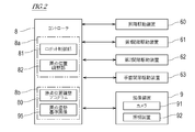
- FIG. 2 is a diagram showing a configuration of a control system of the robot shown in FIG.
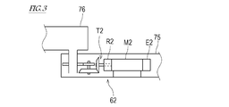
- FIG. 3 is a diagram illustrating a configuration of a joint driving device.
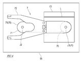
- FIG. 4 is a diagram illustrating an example of the origin posture reference image.
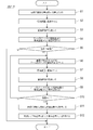
- FIG. 5 is a flowchart of the origin position adjustment processing.
- the present invention is described as applied to a substrate transport robot that transports a substrate in a clean space.
- the robot to which the present invention is applied is not limited to this, and can be widely applied to a robot including a robot arm having at least one joint, including a horizontal articulated robot and a vertical articulated robot.
- FIG. 1 is a diagram showing a schematic configuration of the robot 7 according to the present embodiment
- FIG. 2 is a diagram showing a configuration of a control system of the robot 7 shown in FIG.
- the robot 7 includes a robot arm (hereinafter simply referred to as “arm 71”) and a substrate holding hand (hereinafter simply referred to as “hand”) as an end effector connected to the wrist of the arm 71. 72 ”), a base 73 that supports the arm 71, the imaging device 9 attached to the arm 71 or the hand 72, and the controller 8.
- the arm 71 has a plurality of links 70, 75, 76 connected via the joints J1, J2.
- the plurality of links include a lifting link 70 supported on a base 73 so as to be able to move up and down, and at least one horizontal link 75, 76.
- the base end of the first link 75 is connected to the upper end of the lifting link 70 via the first joint J1
- the base end of the second link 76 is connected to the distal end of the first link 75. They are connected via a joint J2.
- the proximal end of the hand 72 is connected to the distal end of the second link 76 via a wrist joint J3.
- the first joint J1, the second joint J2, and the wrist joint J3 are joints that connect the two elements rotatably about a vertical axis.
- the hand 72 includes a hand base 51 connected to the tip of the arm 71 and a blade 52 connected to the hand base 51.
- the blade 52 is provided with a holding device (not shown) for holding the substrate 6. This holding device may be adapted to prevent the substrate 6 placed on the blade 52 from falling off the blade 52 by fitting, adsorbing, holding, or otherwise.
- a first joint driving device 61 for driving the first joint J1 and a second joint driving device 62 for driving the second joint J2 are provided in the first link 75.
- a wrist joint driving device 63 that drives the wrist joint J3 is provided in the second link 76.
- the driving devices 61 to 63 of the joints J1 to J3 have substantially the same structure. That is, as shown in FIG. 3, the driving devices 61 to 63 for the joints J1 to J3 include servo motors M1 to M3 that perform angular displacement according to a signal given from the controller 8, and servo motors M1 to M3 that include deceleration devices R1 to R3.
- Power transmission mechanisms T1 to T3 for transmitting the power of the servomotors M to the links 75 and 76 (or the hand 72), and position detectors E1 to E3 for detecting angular displacements of the servo motors M1 to M3.
- a driving device 62 is shown as a representative of the driving devices 61 to 63.
- the numbers attached to M, R, T, and E in FIG. At 63, the configuration of each of the driving devices 61 to 63 is shown by replacing the number attached to M, R, T, E in FIG.
- an elevating drive device 60 that drives the elevating link 70 up and down.
- the lifting drive device 60 includes, for example, a servomotor M0 that angularly displaces in accordance with a signal given from the controller 8, a power transmission mechanism T0 that includes a speed reduction device R0, converts the power of the servomotor into a linear force, and transmits the power to the lifting link 70. And a position detector E0 for detecting an angular displacement of the servo motor M0.
- the imaging device 9 includes a camera 91 and an irradiation device 92 that irradiates light to an imaging range of the camera 91.
- the imaging device 9 is attached to the arm 71 or the hand 72 so that the imaging range includes the whole of the arm 71 and the hand 72 in the origin posture described later.
- the imaging device 9 is attached to the hand 72 via a stay so as not to interfere with the arm 71 and the substrate 6 to be held, but the imaging device 9 may be attached to the arm 71.
- the imaging device 9 is supported by a movable stay that displaces the imaging device 9 to a position where the imaging range includes the entire arm 71 and the hand 72 in the origin posture when adjusting the origin position described below. May be.
- the controller 8 controls operations of the arm 71, the hand 72, and the imaging device 9.
- the controller 8 includes a robot control unit 81 and an origin position adjustment unit 82.
- the controller 8 is a so-called computer and includes, for example, a processor 8a such as a microcontroller, CPU, MPU, PLC, DSP, ASIC, or FPGA, and a memory 8b such as a ROM or a RAM.
- the memory 8b stores programs executed by the processor 8a including the origin position adjustment program 80.
- the memory 8b stores data used for processing performed by the processor 8a.
- the processor 8a reads and executes the program stored in the memory 8b, so that processing for functioning as the robot control unit 81 and the origin position adjusting unit 82 is performed.
- the controller 8 may execute each process by centralized control by a single computer, or may execute each process by distributed control in cooperation with a plurality of computers.
- the robot control unit 81 of the controller 8 controls the operation of the robot 7. More specifically, the robot controller 81 is electrically connected to the lifting drive device 60, the first joint drive device 61, the second joint drive device 62, and the first wrist joint drive device 63.
- the robot controller 81 acquires the rotational positions of the servo motors M0 to M3 from the position detectors E0 to E3 included in these driving devices 60 to 63, and poses (position and posture) of the hand 72 corresponding to those rotational positions. ) Is calculated based on the stored teaching point data. Further, the robot control unit 81 outputs a control command to the servo amplifier so that the hand 72 has the target pose.
- the servo amplifier supplies the driving power to each of the servo motors M0 to M3 based on the control command, so that the hand 72 moves to the target pose.
- the origin position adjustment unit 82 of the controller 8 adjusts the origin position of the robot 7.
- the robot 7 has a predetermined origin posture.
- FIG. 4 is an origin posture reference image 95 obtained by imaging the arm 71 and the hand 72 of the robot 7 in the origin posture with the imaging device 9. In FIG. 4, a stay for supporting the imaging device 9 is omitted.
- the original positions of the arm 71 and the hand 72 of the robot 7 are (i) a predetermined horizontal origin reference line L defined on the base 73 and the longitudinal direction of the first link 75.
- the direction, the longitudinal direction of the second link 76, and the longitudinal direction of the hand 72 are parallel, (ii) the first link 75, the second link 76, and the hand 72 overlap in plan view, and (iii) This is a posture in which the rotation axis of one joint J1 and the rotation axis of the third joint J3 are arranged on the same straight line.
- the origin reference line L may be marked on the base 73 or the floor on which the base 73 is installed. However, the origin posture of the robot 7 may be arbitrarily determined.
- the controller 8 causes the imaging device 9 to arm the arm.
- the image of the hand 71 and the hand 72 is taken and stored as an origin posture reference image 95.
- the origin posture reference image 95 may be a pseudo image of an image obtained by imaging the arm 71 and the hand 72 in the origin posture with the imaging device 9.
- the origin posture reference image 95 is not limited to an image obtained by imaging with the imaging device 9, but may be an image created by imitating the image, an image representing the position of a feature point (for example, an outline), or the like. You may.
- the controller 8 determines the rotational positions of the joints J1 to J3. It acquires from the detectors E1 to E3 and stores them as origin positions (initial origin positions) for the joints J1 to J3.
- the arm 71 and the hand 72 of the robot 7 are adjusted to have the origin posture, but the arm 71 and the hand 72 may collide with an object.
- the joints J1 to J3 are continuously used for a long period of time, the joints J1 to J3 may be misaligned, and the arm 71 and the hand 72 may not be in the original positions even if the joints J1 to J3 are set to the original positions.
- the origin position adjusting unit 82 detects such an origin position shift, and adjusts the origin position according to the degree of the origin position shift.
- the method of adjusting the origin position will be described with reference to FIG.
- the origin position adjustment process includes a process relating to detection of the origin position deviation, and a process of adjusting the origin position such that the origin position deviation is eliminated when the origin position deviation is detected.
- the controller 8 that has started the origin position adjustment processing first operates the driving devices 61 to 63 so that the rotational positions of the joints J1 to J3 become the origin positions (step S1).
- the controller 8 causes the image capturing device 9 to capture an image (step S2).
- the imaging range of the imaging device 9 includes the arm 71 and the hand 72 in the current posture.
- the controller 8 acquires the captured image from the imaging device 9 (step S3), and by image processing, the arm 71 and the hand 72 included in the origin attitude reference image 95 of the current attitude of the arm 71 and the hand 72 included in the captured image. Is determined from the original posture (step S4).
- the controller 8 compares the captured image with the origin posture reference image 95 by a known image processing method, extracts a difference between them, and based on the extracted difference, deviates the current posture from the origin posture.
- the controller 8 extracts the profiles of the links 75 and 76 and the hand 72 included in the captured image by image processing, specifies the longitudinal directions of the links 75 and 76 and the hand 72 in the captured image, and The inclination from the origin reference line L in the captured image may be determined as the deviation of the current posture from the origin posture. The deviation of the current posture from the origin posture may be obtained for each link and each hand.
- the controller 8 compares the obtained deviation with a threshold value stored in advance. If the deviation exceeds the threshold value (YES in step S5), the controller 8 determines that there is an "origin position deviation”. (NO in step S5), it is determined that there is no “origin position shift”, and the process is terminated.
- Step S5 When the “origin position shift” is detected (YES in step S5), a process of adjusting the origin position is subsequently performed.
- the controller 8 changes the attitude of the arm 71 and the hand 72 by operating the driving devices 61 to 63 based on the obtained deviation so as to eliminate the deviation (Step S6).
- the controller 8 causes the imaging device 9 to take an image (Step S7).
- the imaging range of the imaging device 9 includes the arm 71 and the hand 72 in the new current posture.
- the controller 8 acquires the captured image (step S8), and by image processing, the origin of the arm 71 and the hand 72 included in the origin attitude reference image 95 of the new current attitude of the arm 71 and the hand 72 included in the captured image.
- a deviation from the posture is determined (step S9).
- the method of calculating the deviation may be the same as the method of calculating the deviation of the current posture from the original posture.
- the controller 8 repeats steps S6 to S9 until the deviation of the new current posture from the original posture becomes substantially zero (YES in step S10). It should be noted that substantially zero may include zero and a sufficiently small value.
- the controller 8 acquires the rotational positions of the joints J1 to J3 at that time from the position detectors E1 to E3 ( (Step S11), these are stored as new origin positions (Step S12), and the process ends.
- the robot 7 of the present embodiment includes the robot arm 71 having the plurality of links 70, 75, and 76 connected via the joints J1 and J2, and the wrist joint J3 at the distal end of the robot arm 71.
- An end effector 72 connected to the end effector 72, an imaging device 9 attached to the end effector 72 or the robot arm 71, and a controller 8 for controlling operations of the robot arm 71 and the imaging device 9 are provided.
- the rotational positions of the joints J1 and J2 and the wrist joint J3 when the end effector 72 and the robot arm 71 are in the predetermined origin posture are defined as the origin positions.
- the imaging device 9 is attached to the end effector 72 or the robot arm 71 so that the imaging range includes the entire end effector 72 and the robot arm 71 in the original posture.
- the controller 8 includes a memory 8b storing an origin position adjustment program 80 and an origin posture reference image 95, and a processor 8a for executing the origin position adjustment program 80.
- the processor 8a causes the rotation positions of the joints J1 and J2 and the wrist joint J3 to be the origin position, causes the imaging device 9 to take an image, and obtains the captured image.
- the deviation of the current posture of the end effector 72 and the robot arm 71 from the original posture is determined, and the presence or absence of the origin position deviation is determined based on the deviation.
- the controller 8 sets the rotational positions of the joints J1 and J2 and the wrist joint J3 as the origin position, causes the imaging device 9 to take an image and obtains the taken image, and controls the end effector 72 and the robot arm 71 in the origin posture.
- the controller 8 compares the expressed origin posture reference image 95 with the captured image, a deviation of the current posture of the end effector 72 and the robot arm 71 from the origin posture is determined, and based on the deviation, it is determined whether or not there is a deviation in the origin position.
- the method of adjusting the origin position of the robot 7 includes setting the rotational positions of the joints J1 and J2 and the wrist joint J3 to the origin position, capturing an image with the imaging device 9 and acquiring the captured image,
- the deviation of the current posture of the end effector 72 and the robot arm 71 from the origin posture is determined by comparing the photographed image with the origin posture reference image 95 representing the end effector 72 and the robot arm 71 in posture. Judge the presence or absence of the origin position deviation based on the
- the robot 7 uses the image captured by the imaging device 9 mounted on the robot 7 to set the original attitude of the current attitude (that is, the original attitude) of the end effector 72 and the robot arm 71. Find the deviation from. Therefore, when adjusting the origin position, the robot 7 does not need to attach / detach a dedicated jig or a sensor, and there is no need for an operator to contact the robot 7. Therefore, even in the robot 7 installed in a sealed space, such as a substrate transfer robot, the origin position adjustment (more specifically, the confirmation of the origin position) is performed at an arbitrary timing without being limited to the time of maintenance. Can be. Further, the origin position can be automatically confirmed without the intervention of the operator.
- the origin position adjustment program 80 in the robot 7 includes the end effector 72 and the robot arm so that the deviation is eliminated when the processor 8a determines that the origin position is shifted.
- the attitude of 71 By changing the attitude of 71, causing the image capturing apparatus 9 to capture the image, acquiring the captured image, and comparing the captured image with the origin attitude reference image 95, the deviation of the new current attitude from the origin attitude is determined. It may be configured to repeat until the deviation becomes substantially zero, and store the rotational positions of the joints J1 and J2 and the wrist joint J3 when the deviation becomes substantially zero as a new origin position.
- the controller 8 of the robot 7 determines that there is a deviation in the origin position
- the controller 8 changes the postures of the end effector 72 and the robot arm 71 so that the deviation is eliminated, and causes the imaging device 9 to take an image.
- Obtaining an image and comparing the captured image with the origin posture reference image 95 to obtain a deviation from the origin posture of the new current posture are repeated until the deviation becomes substantially zero, and the deviation is substantially reduced.
- the rotational positions of the joints J1 and J2 and the wrist joint J3 when they become zero may be stored as new origin positions.
- the origin position adjustment method of the robot determines that there is an origin position deviation
- the posture of the end effector 72 and the robot arm 71 is changed so that the deviation is eliminated, and the imaging device 9 is caused to take an image.
- Obtaining the deviation from the origin posture of the new current posture by comparing the photographed image with the origin posture reference image 95 until the deviation becomes substantially zero; And storing the rotational positions of the joints J1, J2 and the wrist joint J3 when the deviation becomes substantially zero as a new origin position.
- the robot 7 uses the image captured by the imaging device 9 mounted on the robot 7 to joint the end effector 72 and the robot arm 71 so that the current attitude matches the original attitude.
- a new origin position that is, an adjusted origin position
- the robot 7 does not need to attach / detach a dedicated jig or a sensor when adjusting the origin position, and does not require the operator to contact the robot. Therefore, even with the robot 7 installed in a sealed space like a substrate transfer robot, for example, the origin position can be adjusted at an arbitrary timing without being limited to maintenance. Further, the origin position can be automatically adjusted without the intervention of the operator.
Landscapes
- Engineering & Computer Science (AREA)
- Robotics (AREA)
- Mechanical Engineering (AREA)
- Health & Medical Sciences (AREA)
- General Health & Medical Sciences (AREA)
- Orthopedic Medicine & Surgery (AREA)
- Human Computer Interaction (AREA)
- Manipulator (AREA)
Abstract
Description
関節を介して連接された複数のリンクを有するロボットアームと、
前記ロボットアームの先端に手首関節を介して連結されたエンドエフェクタと、
前記エンドエフェクタ及び前記ロボットアームが所定の原点姿勢にあるときの前記関節及び前記手首関節の回転位置を原点位置とし、撮像範囲に前記原点姿勢の前記エンドエフェクタ及び前記ロボットアームの全体が含まれるように前記エンドエフェクタ又は前記ロボットアームに取り付けられた撮像装置と、
前記ロボットアーム及び前記撮像装置の動作を制御するコントローラと、を備え、
前記コントローラは、前記関節及び前記手首関節の回転位置を前記原点位置とさせ、前記撮像装置に撮像させてその撮像画像を取得し、前記原点姿勢の前記エンドエフェクタ及び前記ロボットアームを表した原点姿勢基準画像と前記撮像画像とを比較することにより、前記エンドエフェクタ及び前記ロボットアームの現在姿勢の前記原点姿勢からの偏差を求め、当該偏差に基づいて原点位置ズレの有無を判断することを特徴としている。
関節を介して連接された複数のリンクを有するロボットアームと、前記ロボットアームの先端に手首関節を介して連結されたエンドエフェクタと、前記エンドエフェクタ及び前記ロボットアームが所定の原点姿勢にあるときの前記関節及び前記手首関節の回転位置を原点位置とし、撮像範囲に前記原点姿勢の前記エンドエフェクタ及び前記ロボットアームが含まれるように前記エンドエフェクタ又は前記ロボットアームに取り付けられた撮像装置とを備えたロボットの原点位置調整方法であって、
前記関節及び前記手首関節の回転位置を前記原点位置にすること、
前記撮像装置で撮像し、その撮像画像を取得すること、
前記原点姿勢の前記エンドエフェクタ及び前記ロボットアームを表した原点姿勢基準画像と前記撮像画像とを比較することにより、前記エンドエフェクタ及び前記ロボットアームの現在姿勢の前記原点姿勢からの偏差を求めること、及び、
前記偏差に基づいて原点位置ズレの有無を判断すること、を含むことを特徴としている。
先ず、本実施形態に係るロボット7の構成について説明する。図1は、本実施形態に係るロボット7の概略構成を示す図であり、図2は、図1に示すロボット7の制御系統の構成を示す図である。
原点位置調整処理は、原点位置ズレの検出に係る処理と、原点位置ズレが検出された場合に原点位置ズレが解消されるように原点位置を調整する処理とを含む。図5に示すように、原点位置調整処理を開始したコントローラ8は、先ず、関節J1~J3の回転位置が原点位置となるように各駆動装置61~63を動作させる(ステップS1)。次に、コントローラ8は、撮像装置9に撮像させる(ステップS2)。撮像装置9の撮像範囲には、現在姿勢のアーム71及びハンド72が含まれる。
7 :ロボット
8 :コントローラ
8a :プロセッサ
8b :メモリ
9 :撮像装置
51 :ハンド基部
52 :ブレード
60~63 :駆動装置
70,75,76 :リンク
71 :ロボットアーム
72 :ハンド(エンドエフェクタの一例)
73 :基台
80 :原点位置調整プログラム
81 :ロボット制御部
82 :原点位置調整部
91 :カメラ
92 :照射装置
E0~E3 :位置検出器
J1~J3 :関節
L :原点基準線
M0~M3 :サーボモータ
R0~R3 :減速装置
T0~T3 :動力伝達機構
Claims (4)
- 関節を介して連接された複数のリンクを有するロボットアームと、
前記ロボットアームの先端に手首関節を介して連結されたエンドエフェクタと、
前記エンドエフェクタ及び前記ロボットアームが所定の原点姿勢にあるときの前記関節及び前記手首関節の回転位置を原点位置とし、撮像範囲に前記原点姿勢の前記エンドエフェクタ及び前記ロボットアームの全体が含まれるように前記エンドエフェクタ又は前記ロボットアームに取り付けられた撮像装置と、
前記ロボットアーム及び前記撮像装置の動作を制御するコントローラと、を備え、
前記コントローラは、前記関節及び前記手首関節の回転位置を前記原点位置とさせ、前記撮像装置に撮像させてその撮像画像を取得し、前記原点姿勢の前記エンドエフェクタ及び前記ロボットアームを表した原点姿勢基準画像と前記撮像画像とを比較することにより、前記エンドエフェクタ及び前記ロボットアームの現在姿勢の前記原点姿勢からの偏差を求め、当該偏差に基づいて原点位置ズレの有無を判断する、
ロボット。 - 前記コントローラは、
前記原点位置ズレが有ると判断した場合に、前記偏差が解消されるように前記エンドエフェクタ及び前記ロボットアームの姿勢を変化させ、前記撮像装置に撮像させてその撮像画像を取得し、前記撮像画像を前記原点姿勢基準画像と比較することにより、新たな現在姿勢の前記原点姿勢からの偏差を求めることを、当該偏差が実質的にゼロになるまで繰り返し、前記偏差が実質的にゼロになったときの前記関節及び前記手首関節の回転位置を新たな原点位置として記憶する、
請求項1に記載のロボット。 - 関節を介して連接された複数のリンクを有するロボットアームと、前記ロボットアームの先端に手首関節を介して連結されたエンドエフェクタと、前記エンドエフェクタ及び前記ロボットアームが所定の原点姿勢にあるときの前記関節及び前記手首関節の回転位置を原点位置とし、撮像範囲に前記原点姿勢の前記エンドエフェクタ及び前記ロボットアームが含まれるように前記エンドエフェクタ又は前記ロボットアームに取り付けられた撮像装置とを備えたロボットの原点位置調整方法であって、
前記関節及び前記手首関節の回転位置を前記原点位置にすること、
前記撮像装置で撮像し、その撮像画像を取得すること、
前記原点姿勢の前記エンドエフェクタ及び前記ロボットアームを表した原点姿勢基準画像と前記撮像画像とを比較することにより、前記エンドエフェクタ及び前記ロボットアームの現在姿勢の前記原点姿勢からの偏差を求めること、及び、
前記偏差に基づいて原点位置ズレの有無を判断すること、を含む、
ロボットの原点位置調整方法。 - 前記原点位置ズレが有ると判断された場合に、前記偏差が解消されるように前記エンドエフェクタ及び前記ロボットアームの姿勢を変化させ、前記撮像装置に撮像させてその撮像画像を取得し、前記撮像画像を前記原点姿勢基準画像と比較することにより、新たな現在姿勢の前記原点姿勢からの偏差を求めることを、当該偏差が実質的にゼロになるまで繰り返すこと、及び、
前記偏差が実質的にゼロになったときの前記関節及び前記手首関節の回転位置を新たな原点位置として記憶すること、を更に含む、
請求項3に記載のロボットの原点位置調整方法。
Priority Applications (3)
| Application Number | Priority Date | Filing Date | Title |
|---|---|---|---|
| CN201980055710.5A CN112672854A (zh) | 2018-08-31 | 2019-08-23 | 机器人及其原点位置调整方法 |
| JP2020539414A JPWO2020045277A1 (ja) | 2018-08-31 | 2019-08-23 | ロボット及びその原点位置調整方法 |
| KR1020217008286A KR20210048516A (ko) | 2018-08-31 | 2019-08-23 | 로봇 및 그 원점 위치 조정 방법 |
Applications Claiming Priority (2)
| Application Number | Priority Date | Filing Date | Title |
|---|---|---|---|
| US16/119,634 US20200070349A1 (en) | 2018-08-31 | 2018-08-31 | Robot and method of adjusting original position of robot |
| US16/119,634 | 2018-08-31 |
Publications (1)
| Publication Number | Publication Date |
|---|---|
| WO2020045277A1 true WO2020045277A1 (ja) | 2020-03-05 |
Family
ID=69642228
Family Applications (1)
| Application Number | Title | Priority Date | Filing Date |
|---|---|---|---|
| PCT/JP2019/033025 Ceased WO2020045277A1 (ja) | 2018-08-31 | 2019-08-23 | ロボット及びその原点位置調整方法 |
Country Status (6)
| Country | Link |
|---|---|
| US (1) | US20200070349A1 (ja) |
| JP (1) | JPWO2020045277A1 (ja) |
| KR (1) | KR20210048516A (ja) |
| CN (1) | CN112672854A (ja) |
| TW (1) | TW202023770A (ja) |
| WO (1) | WO2020045277A1 (ja) |
Cited By (3)
| Publication number | Priority date | Publication date | Assignee | Title |
|---|---|---|---|---|
| WO2022196712A1 (ja) * | 2021-03-19 | 2022-09-22 | 川崎重工業株式会社 | ウエハ搬送ロボット及びウエハ取出方法 |
| JP2024093887A (ja) * | 2022-12-27 | 2024-07-09 | 株式会社ダイヘン | ロボット制御装置及びロボット教示方法 |
| JP2024094061A (ja) * | 2022-12-27 | 2024-07-09 | 株式会社ダイヘン | ロボット制御装置及びロボット教示方法 |
Families Citing this family (6)
| Publication number | Priority date | Publication date | Assignee | Title |
|---|---|---|---|---|
| JP7364371B2 (ja) * | 2019-06-28 | 2023-10-18 | 川崎重工業株式会社 | 基板搬送ロボット及び基板搬送ロボットの制御方法 |
| JP7396495B2 (ja) * | 2020-07-29 | 2023-12-12 | 株式会社タダノ | 地切り制御装置、及び、移動式クレーン |
| US12046501B2 (en) * | 2022-10-06 | 2024-07-23 | Kawasaki Jukogyo Kabushiki Kaisha | Substrate handling apparatus and method of handling substrate |
| CN116009599B (zh) * | 2022-10-31 | 2026-04-07 | 湖南视比特机器人有限公司 | 载具末端设备的定位方法、装置、载具、存储介质和终端 |
| CA3224875A1 (en) * | 2022-12-27 | 2024-06-27 | Pratt & Whitney Canada Corp. | Robotic polishing system and method for using same |
| US12667975B2 (en) * | 2022-12-27 | 2026-06-30 | Pratt & Whitney Canada Corp. | Robotic polishing system and method for using same |
Citations (5)
| Publication number | Priority date | Publication date | Assignee | Title |
|---|---|---|---|---|
| JP2012223871A (ja) * | 2011-04-21 | 2012-11-15 | Kawasaki Heavy Ind Ltd | ロボットの関節の原点補正方法およびそのシステム |
| JP2018056256A (ja) * | 2016-09-28 | 2018-04-05 | 川崎重工業株式会社 | 基板搬送ハンドの診断システム |
| JP2018069425A (ja) * | 2016-11-04 | 2018-05-10 | 株式会社東芝 | ロボット装置、及びロボット装置の制御方法 |
| CA3043463A1 (en) * | 2016-11-22 | 2018-05-31 | Unibap Ab | Measurement system and method of an industrial robot |
| JP2018083270A (ja) * | 2016-11-25 | 2018-05-31 | シャープ株式会社 | ロボット姿勢校正装置、ロボット姿勢校正方法、ロボット姿勢校正プログラム、及び記録媒体 |
Family Cites Families (6)
| Publication number | Priority date | Publication date | Assignee | Title |
|---|---|---|---|---|
| JPH08155866A (ja) | 1994-04-06 | 1996-06-18 | Seiko Seiki Co Ltd | 産業用ロボットのキャリブレーション方法およびその治具 |
| JP3396545B2 (ja) | 1994-09-28 | 2003-04-14 | 株式会社リコー | ロボット装置の原点較正装置及び双腕型ロボット装置 |
| US20060167583A1 (en) * | 2005-01-22 | 2006-07-27 | Applied Materials, Inc. | Method and apparatus for on the fly positioning and continuous monitoring of a substrate in a chamber |
| JP5571902B2 (ja) * | 2009-03-17 | 2014-08-13 | 川崎重工業株式会社 | ロボット、及びオートゼロイング方法 |
| JP5365379B2 (ja) * | 2009-07-06 | 2013-12-11 | 富士電機株式会社 | ロボットシステム及びロボットシステムのキャリブレーション方法 |
| CN105522576A (zh) * | 2014-10-27 | 2016-04-27 | 广明光电股份有限公司 | 机器手臂自动再校正的方法 |
-
2018
- 2018-08-31 US US16/119,634 patent/US20200070349A1/en not_active Abandoned
-
2019
- 2019-08-23 KR KR1020217008286A patent/KR20210048516A/ko not_active Withdrawn
- 2019-08-23 CN CN201980055710.5A patent/CN112672854A/zh active Pending
- 2019-08-23 JP JP2020539414A patent/JPWO2020045277A1/ja active Pending
- 2019-08-23 WO PCT/JP2019/033025 patent/WO2020045277A1/ja not_active Ceased
- 2019-08-29 TW TW108131074A patent/TW202023770A/zh unknown
Patent Citations (5)
| Publication number | Priority date | Publication date | Assignee | Title |
|---|---|---|---|---|
| JP2012223871A (ja) * | 2011-04-21 | 2012-11-15 | Kawasaki Heavy Ind Ltd | ロボットの関節の原点補正方法およびそのシステム |
| JP2018056256A (ja) * | 2016-09-28 | 2018-04-05 | 川崎重工業株式会社 | 基板搬送ハンドの診断システム |
| JP2018069425A (ja) * | 2016-11-04 | 2018-05-10 | 株式会社東芝 | ロボット装置、及びロボット装置の制御方法 |
| CA3043463A1 (en) * | 2016-11-22 | 2018-05-31 | Unibap Ab | Measurement system and method of an industrial robot |
| JP2018083270A (ja) * | 2016-11-25 | 2018-05-31 | シャープ株式会社 | ロボット姿勢校正装置、ロボット姿勢校正方法、ロボット姿勢校正プログラム、及び記録媒体 |
Cited By (5)
| Publication number | Priority date | Publication date | Assignee | Title |
|---|---|---|---|---|
| WO2022196712A1 (ja) * | 2021-03-19 | 2022-09-22 | 川崎重工業株式会社 | ウエハ搬送ロボット及びウエハ取出方法 |
| JP2022144478A (ja) * | 2021-03-19 | 2022-10-03 | 川崎重工業株式会社 | ウエハ搬送ロボット及びウエハ取出方法 |
| JP7779661B2 (ja) | 2021-03-19 | 2025-12-03 | 川崎重工業株式会社 | ウエハ搬送ロボット及びウエハ取出方法 |
| JP2024093887A (ja) * | 2022-12-27 | 2024-07-09 | 株式会社ダイヘン | ロボット制御装置及びロボット教示方法 |
| JP2024094061A (ja) * | 2022-12-27 | 2024-07-09 | 株式会社ダイヘン | ロボット制御装置及びロボット教示方法 |
Also Published As
| Publication number | Publication date |
|---|---|
| KR20210048516A (ko) | 2021-05-03 |
| US20200070349A1 (en) | 2020-03-05 |
| TW202023770A (zh) | 2020-07-01 |
| CN112672854A (zh) | 2021-04-16 |
| JPWO2020045277A1 (ja) | 2021-08-10 |
Similar Documents
| Publication | Publication Date | Title |
|---|---|---|
| JPWO2020045277A1 (ja) | ロボット及びその原点位置調整方法 | |
| CN108214454B (zh) | 机器人系统、机器人控制装置及机器人控制方法 | |
| US10864632B2 (en) | Direct teaching method of robot | |
| CN107848113B (zh) | 机器人系统及其运转方法 | |
| US10279485B2 (en) | Robot system and method of detecting deformation of end effector | |
| US11904483B2 (en) | Work robot system | |
| US11230005B2 (en) | Following robot and work robot system | |
| JP5272617B2 (ja) | ロボット装置及びロボット装置の制御方法 | |
| WO2017064851A1 (ja) | ロボット教示方法及びロボットアーム制御装置 | |
| US20220088795A1 (en) | Manipulator controller, manipulator control method, and non-transitory computer-readable storage medium storing manipulator control program | |
| CN110267770A (zh) | 机器人系统及其控制方法 | |
| JP6924112B2 (ja) | 基板搬送装置及び基板搬送ロボットと基板載置部との位置関係を求める方法 | |
| US11878423B2 (en) | Robot system | |
| US20180207804A1 (en) | Process system including robot that transfers workpiece to process machine | |
| WO2018066602A1 (ja) | ロボットシステム及びその運転方法 | |
| JP2018056256A (ja) | 基板搬送ハンドの診断システム | |
| WO2020044760A1 (ja) | 動作装置のキャリブレーション方法、動作装置システムおよび制御装置 | |
| US20220032448A1 (en) | Teaching method and robot system | |
| JP3328414B2 (ja) | ロボットハンドの姿勢制御装置 | |
| WO2018066601A1 (ja) | ロボットシステム及びその運転方法 | |
| JP7556667B2 (ja) | ロボットシステム及びロボットシステムの制御方法 | |
| JP7578007B2 (ja) | ロボットの制御方法およびロボットシステム | |
| WO2019107208A1 (ja) | 作業機の動作制御方法 | |
| US10867821B2 (en) | Substrate transfer robot and method of teaching edge position of target body | |
| CN112262025B (zh) | 机器人系统及其运转方法 |
Legal Events
| Date | Code | Title | Description |
|---|---|---|---|
| 121 | Ep: the epo has been informed by wipo that ep was designated in this application |
Ref document number: 19856275 Country of ref document: EP Kind code of ref document: A1 |
|
| ENP | Entry into the national phase |
Ref document number: 2020539414 Country of ref document: JP Kind code of ref document: A |
|
| NENP | Non-entry into the national phase |
Ref country code: DE |
|
| ENP | Entry into the national phase |
Ref document number: 20217008286 Country of ref document: KR Kind code of ref document: A |
|
| 122 | Ep: pct application non-entry in european phase |
Ref document number: 19856275 Country of ref document: EP Kind code of ref document: A1 |